on the compression of a cylinder in contact with a … 73-243 on the compression of a cylinder...
TRANSCRIPT
, I
' '
NBSIR 73-243
On the Compression of a Cylinder Contact with a Plane Surface
B. Nelson Norden
Institute for Basic StandardsNational Bureau of Standards
Washington , D. C. 20234
July 19 , 1973
Final Report
u .S. DEPARTMENT OF COMMERCE
NATIONAL BUREAU OF STANDARDS
NBSIR 73-243
ON THE COMPRESSION OF A CYLINDER
CONTACT WITH A PLANE SURFACE
Nelson Norden
Institute for Basic StandardsN ationa I Bureau of StandardsWashington , D. C. 20234
July 19 , 1973
Final Report
U. S. DEPARTMENT OF COMMERCE, Frederick B. Dent, Secretary
NATIONAL BUREAU OF STANDARDS, Richard W. RobertS. Director
CONTENTS
Page
List of Illustrations
Nomenclature iiilntroduc t ion
General Description of Contact Problem Between Two Elastic Bodies
Special Case of Line Contact
Experimental Verification
Conclusion
Summary of Equations
References
Illustrations
Figure
Figure
Figure
Figure
Figure
Figure
Figure
Figure
Figure 9
Figure 10.
Figure 11.
Figure 12.
Figure 13.
Figure 14.
LIST OF ILLUSTRATIONS
Geometry of the contact between elliptic paraboloids
Cross section of two contacting surfaces
Geometry of deformed bodies
Measurement of the diameter of a ~ylinder
Contact geometry of two parallel cylinders
Relationship for yield stress as function of surface finish
Compression of 0. 05-inch cylinder between l/4-inch anvils
Total deformation of O.OOI-inch steel cylinder b~tween
3/8-inch anvils
Total deformation of O. OI-inch steel cylinder between
3lB-inch anvils
Total deformation of 1. 00-inch steel cylinder between
3lB-inch anvils
Analysis of total system deformation using equations (55),
(62), (73), (76), and (79)
Analysis of total system deformation using equations (82),
(B3), and (84)
Nomograph for computation of maximum s tress in cylinder-
plane contact
Equation for calculation of compression in cylinder-plane
contact
l' R
2' R
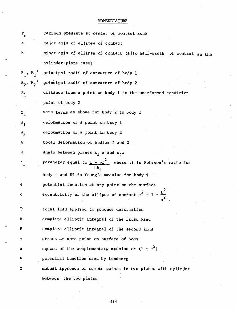
NOMENCLATURE
maximum pressure at center of contact zone
major axis of ellipse of contact
minor axis of ellipse of contact (also half-width of contact in the
cylinder-plane case)
principal radii of curvature of body.
principal radii of curvature of body 2
distance from a point on body 1 to the undeformed condition
point of body 2
same terms as above for body 2 to body I
deformation point body
deformation point body
total deformation of bodies land 2
angle between planes xl z and x
parameter equal to 1 - vi where vi is Poisson I S ratio forTIE.
body i and Ei is Young s modulus for body i
potential function at any point on the surface
2 beccentricity of the ellipse of contact e = 1 -
total load applied to produce deformation
complete elliptic integral of the first kind
complete elliptic integral of the sec.ond kind
stress at some point on surface of body
square of th~ complementary modulus or (1 - e )
potential function used by Lundberg
mutua 1 approach of remote points in two plates with cylinder
between the two plates
iii
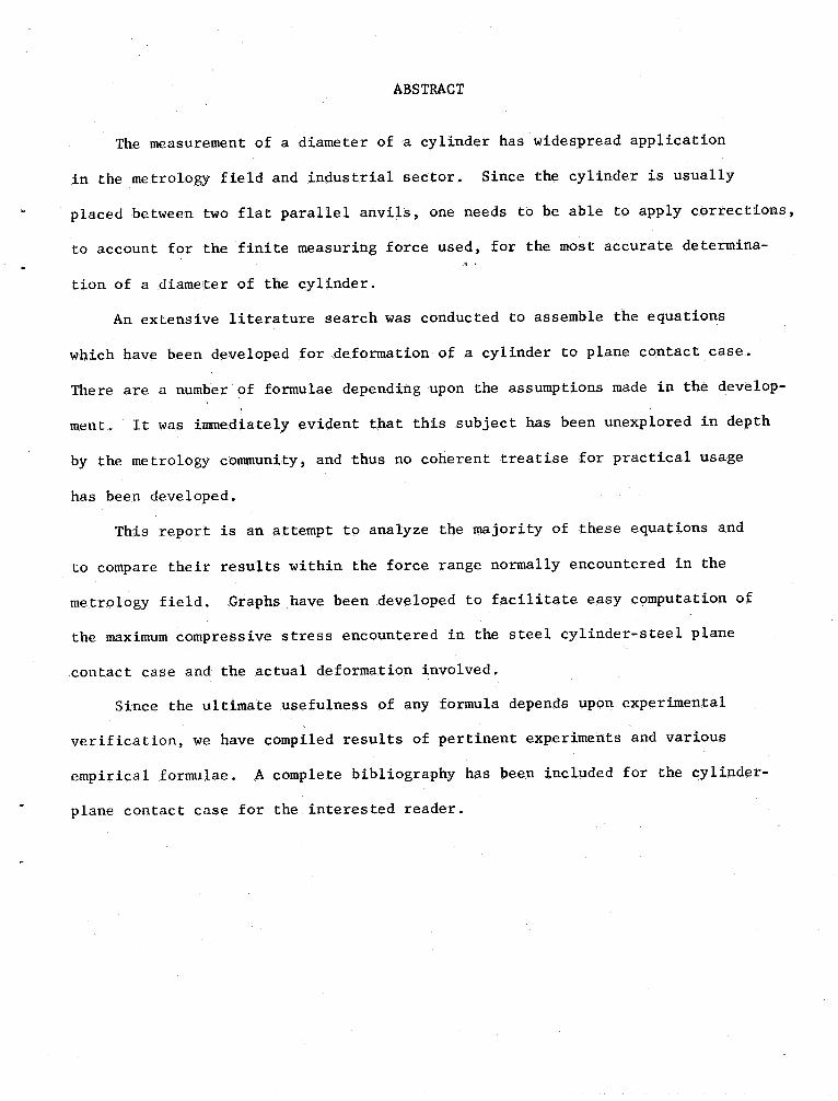
ABSTRACT
The measurement of a diameter of a cylinder has widespread application
in the metrology field and industrial sector. Since the cylinder is usually
placed between two flat parallel anvils, one needs to be able to apply corrections
to account for the finite measuring force used, for the most accurate determina-
tion of a diameter of the cylinder.
An extensive literature search was conducted to assemble the equations
which have been developed for deformation' of a cylinder to plane contact case.
There are a number of formulae depending upon the assumptions made in the develop-
ment. It was immediately evident that this subject has been unexplored in depth
by the metrology community, and thus no coherent treatise for practical usage
has been developed.
This report is an attempt to analyze the majority of these equations and
to compare their results within the force range normally encountered in the
metrology field. Graphs have been developed to facilitate easy computation of
the maximum compressive stress encountered in the steel cylinder-steel plane
contact case and the actual deformation involved.
Since the ultimate usefulness of any formula depends upon experimental
verification , we have compiled results of pertinent experiments and various
empirical formulae. A complete bibliography has been included for the cylinder-
plane contact case for the interested reader.
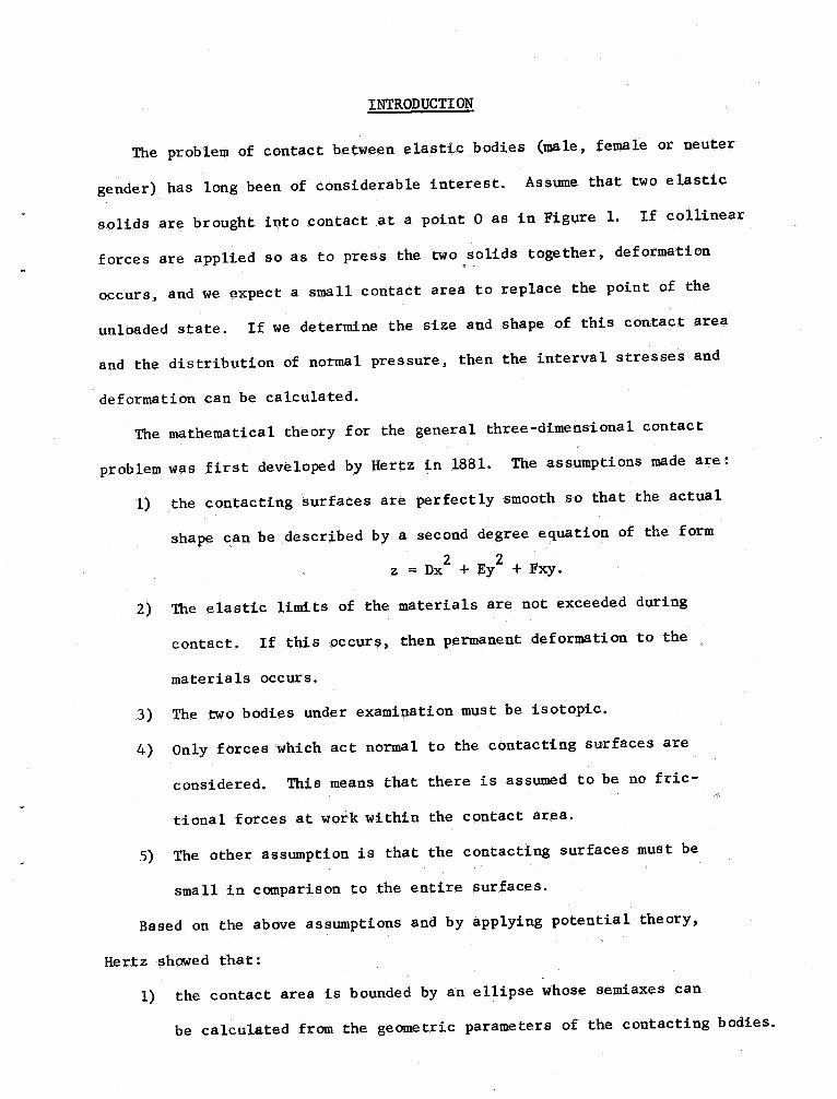
INTRODUCTION
The problem of contact between elastic bodies (male , female or neuter
gender) has long been of considerable interest. Assume that two elastic
solids are brought into contact at a point 0 as in Figure If collinear
forces are applied so as to press the two solids together, deformation
occurs , and we expect a small contact area to replace the point of the
unloaded state. If we determine the size and shape of this contact area
and the distribution of normal pressure, then the interval stresses and
deformation can be calculated.
The mathematical theory for the general three-dimensional contact
problem was first developed by Hertz in 1881. The assumptions made are:
the contacting surfaces are perfectly smooth so that the actual
shape can be described by a second degree equation of the form
z = Dx + Ey + Fxy.
The elastic limits of the materials are not exceeded during
contact. If this occurs, then permanent deformation to the
materials occurs.
The two bodies under examination must be isotopic.
Only forces which act normal to the contacting surfaces are
considered. This means that there is assumed to be no fric-
tional forces at work within the contact area.
The other assumption is that the contacting surfaces must be
small in comparison to the entire surfaces.
Based on the above assumptions and by applying potential theory,
Hertz showed that:
the contact area is bounded by an ellipse whose semiaxes can
be calculated from the geometric parameters of the contacting bodies.
-2-
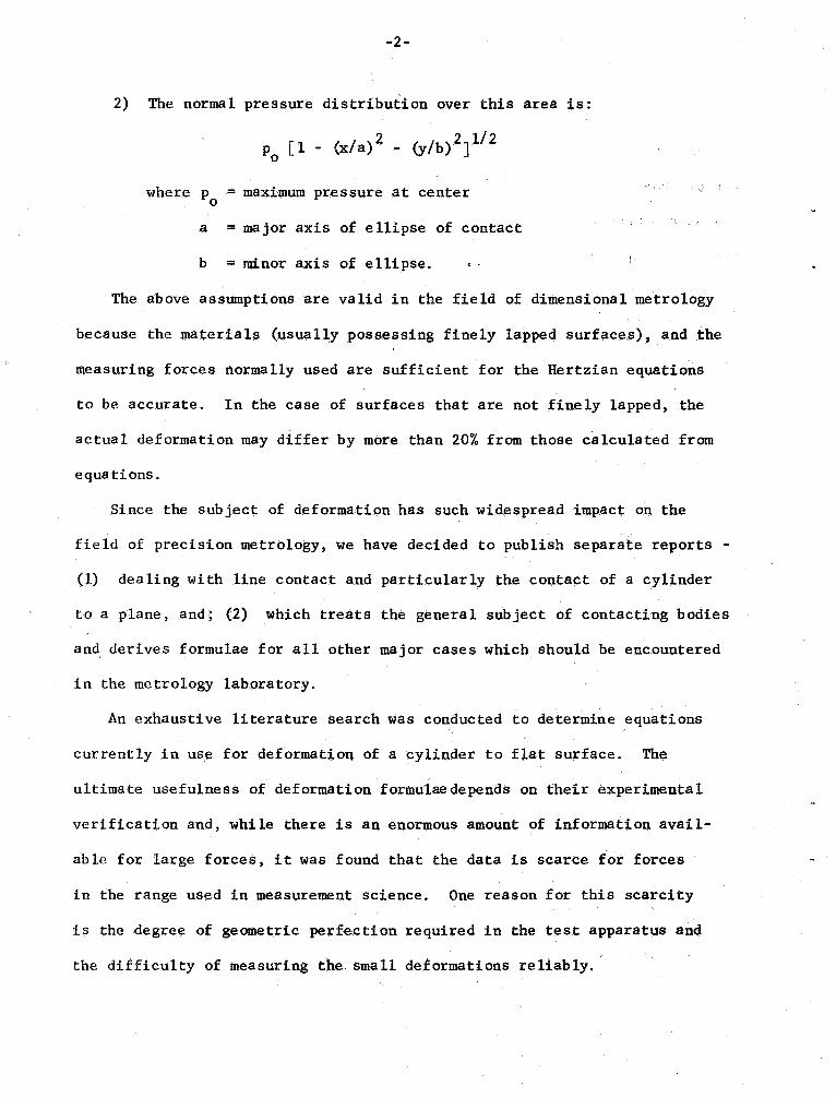
The normal pressure distribution over this area is:
2 1/2(1 - (x/a) - (y/b) J
where p = maximum pressure at center
= major axis of ellipse of contact
= minor axis of ellipse.
The above assumptions are valid in the field of dimensional metrology
because the materials (usually possessing finely lapped surfaces), and the
measuring forces normally used are sufficient for the Hertzian equations
to be accurate. In the case of surfaces that are not fine 1y lapped , the
actual deformation may differ by more than 20% from those ca1cu1a ted from
eqUB tions.
Since the subject of deformation has such widespread impact on the
field of precision metrology, We have decided to publish separate reports -
(1) dealing with line contact and particularly the contact of a cylinder
to a plane , and; (2) which treats the general subject of contacting bodies
and derives formulae for all other major cases which should be encountered
in the metrology laboratory.
An exhaustive literature search was conducted to determine eq.uations
currently in use for deformation of a cylinder to flat surface. The
ultimate usefulness of deformation formulae depends on their experimental
verification and, while there is an enormouS amount of information avai1-
able for large forces, it was found that the data is scarce for forces
in the range used in measurement science. One reason for this scarcity
is the degree of geometric perfection required in the test apparatus and
the difficulty of measuring the small deformations reliably.
Depending upon the assumptions made , there are a number of formulae
in use. Various equations will be analyzed along with the assumptions
inherent in their derivations. There are basically three approaches to
the problem for the deformation of a cylinder with diameter D in contact
with a plane over a length L and under the action of force
the approach where a solution is generated from the general
three-dimensional case of curved bodies by assigning the plane
surface a radius of curvature. This is the same as replacing
the plane surface with a cylindrica 1 surface with a very large
radius of curvature. The area of contact is then a~e10ngated
ellipse.
The approach where the contact area between a cylinder and plane
is assumed to be a finite rectangle of width 2b and length L
where L ~:;::.b.
The determination of compression formula by empirical means.
GENERAL DESCRIPTION OF CONTACT PROBLEM
When two homogen~ous , elastic bodies are pressed together , a certain
amount of deformation will occur in each body, bounded by a curve called
the curve of compression. Th. theory was first developed by H. Hertz ClJ~
Figure 1 shows two general bodies in the unstressed and undeformed
state with a point of contact at The two surfaces have a common tarigeRt
at point O. The principal radii of curvature of the surface at the point
of contact is Rl for body 1
, and R2 for body
R ' and R I repr~sent
the other radii of curvature of each body. The radii of curvature are
measured in two planes at right angles to one another. The principal
radii of curvature may be positive if the center of curvature lies within
the body, .and negative if the center of curvature lies outside the body.
Also planes xl z and
Z should be chosen such that
- +- :;:. -
1 "2. "1 ' "2 '
The angle (j) is the angle between the normal sections of the two bodies
which contain the principal radii of curvature R1 and R
Figure 2 shows a cross-section of the two surfaces near the point of
contact O. We must limit our analysis to the c.ase where the dimensions
of the compressed area after the bodies have been pressed together are
small in comparison with the radii of curvature of bodies 1 and
also assume that the surface of each body near the poin t of contact can
be approximated by a second degree equation of the form
Z = Dx + Ey + 2 Fxy
where D , E and F are arbitrary constants.
-5-
If the two bodies are pressed together by applied normal forces (Figure
3), then a deformation occurs near the original point of contact along the
Z-axis. Here again, we consider only forces acting parallel to the z-axis
where the distance from the z-axis is small.
The displacements at a point are w 1 and ~2 where w I is the deformation
of point P 1 of body 1 and w2 is the deformation of point P2 for body 2
plane C is the origina 1 plane of tangency; z l is the distance from Pl to
the undeformed state , and z2 is the distance from P 2 to the undeformed
state. For points inside the contact area , we have
+ w ) + (z2 + w ) = 0 (1)
where 6 is the total deformation which we are so diligently seeking.
The equation for surface 1 may be written as:
l = D1 x + E1 Y + 2F 1
and for surface 2
z 2 = D 2 x + E 2 Y + 2F 2 xy.
Since the sum of zl and z2 enter into the equation we obtain
l + z2 = (Dl + D)x + (E
l + E)y + 2(F
l + F)xy. (2)
Now Hertz showed that the axis can be transformed so that F 1 = -F 2' and
hence , the xy term vanishes. To simplify the above equation further We
replace the constants (Dl + D
) with A and (El + E
) with B thus giving,
l + z2 = Ax2 + By
From equation (1) we obtain:
2 + By2 + w + w= 6 (3)
The constants A and B are expressible in terms of combinations of
the principal curvatures of the surfaces and the angle between the planes
of curvature. These combinations have been derived by Hertz and are as
follows:
A + B = '2 R1 + ;
' + R~' + ;(4)
B - A = 1 - 1
2 +- 1
2 +
2 R1 R ' R2 R
- 1 - 1 cos 2W1/2
R' R R' (5)
Since the points within the compressed area are in contact after the
compression we have:
1 + w 2 = 6 - Ax -
and since 6 is the value of w1 and 1012 at the. origin (Figure 3 , x = = 0),
e must evaluate wI and w
The pressure P between the bodie.s is the resultant of a distributed
pressure (P' per uni t of area), over the compressed are. From Prescott C2J
the values of the deformations w1 and w2 under the action of normal forces
are:
== Al ~
, y)
(6)
and
2 = A2 ~ (x (7)
where vl.i - TIEi
-7-
i = Poissons ratio for the Lth body
i = Modulus of elasticity for the ith body,
and ~ (x, y) = dx ' dy I which represents the
potential at a point on the surface. ~re r is the distance from Some
point (x, y) to another point (x
, y
) and p". is the surface density.
By substitution in Equation 3 we obtain,
l + A' dy I = 6 - Ax
2 - By (8)
where the subscripts 1 and 2 represent the elastic constants for bodies
1 and 2.
One important Jact should be observed from Equations 6 and 7 and this
is:1 - 1) 2
TIEi
1 -
TIE 2
(9)
which means if the two bodies are made of the same material w1 = w
The integral equation 8 allows one to compute the contact area , the
pressure distribution, and the deformation of the bodies.
The problem is now to find a distribution of pressures to satisfy
equation 8. Since the formula for ip is a potential function due to matter
distributed over the compressed area with surface density P' we see the
analogy between this problem and potential theory. Hertz saw the ana logy
since the integral on the left side of equation 8 is of a type commonly
found in potential theory, where such integralS give the potential of a
distribution of charge and the potential at a point in the interior of a
uniformly charged ellipsoid is a quadratic~ ~unctio~ of the coordinates.
If an ellipsoid = 1 has a uniform charge density p witha b2 cmass npabc, then the potential within the ellipse is given by Kellog (JJ
~.ex , y, z) =
TIP~C~( 1 . 2 + If l: y
((.
2 on) (b
/:
y) (02 + y)) 1/
(10)
If we consider the case where the ellipsoid is very much flattened (c .... 0)
then we have
. (x, y) = TIPabcf(' -
/:~
((82 + ~)(
:~ +~) (~))
~/2(11)
The potentia 1 due a mass density
..1.1L
, y
- 2TIab1 - (l2)
2 ,distributed over the ellipse = 1 in the plane Z = 0, where thea btotal load P is given by,
P = 4/3 TIPC ab. (13)
By substituting into Equation 11 we obtain
4'(", y) .
~I'
: ~ /: ~ ((/ +
'f) (b
/:
~) ('1')) 1/2
(14)
From Equations 8 , 11 and 14 we obtain
1 + A ) 4"
(A + A E.:. ' dy l =2')~ r'A
'J.'1 - ~ + ~ b
~ + ~ ((.
~ + ~)(b2 + ~)(m(15)
Thus we have
' dy l =
/:~ /:
d'J.'
1 ((a2 + 'J.')(b 2 + 'J.'HIf)Y 2
(16)
-9-
We now substitute into Equation 8 to obtain,
1 + A t p 1 -
/:~ /:
2 d
~ \
((a + 'i') (b + 'i') ('i') =
6 - Ax - 2 ..
Since the coefficients of 1 , x , and y must be equal in Equation 17,
(17)
we have
3 P (A + A ) ~oo 'i'
6 ~ 4" 1 2
((.
2 + y) (b2 HHy)r/2(18)
A = ~ P (A1 + A
'i'
0 (a2 + 'i') 3/2 ((b2 + 'i')('i'))1/2(19)
B = p (A1 + A
d'i'
0 (b2 + 'i') 3/2 ((a 2 + 'i')
('i')tI2
(20)
Equations 19 and ZO determine a and b (major and minor axis of the
ellipse of contact) and equation 18 determines the total deformation
(or the normal approach) when a and b are known.
Since the integrals i.n Equations 18, 19 and 20 are somewhat cutnbersome
they may be expressed in terms of complete elliptic integrlii1s where tables
are readi 1y avai lab Ie. Since the eccentricity (e) of any ellipse may be
expressed in terms of the major and minor axis as
2 1/2
= 1 - or e = (1 - ~)
we mliiy express Equations 18, 19 and 20 in terms of the eccentricity of
the contact ellipse.
From Equation 19 we obtain,
-10-
;::: 1. P (A.
+;....
d'i'
2 0 (a2 + 'i') 3/2 2 - a 2 + 'i') 1/2 'i' 1/2
5/2By multiplying the numerator and denominator by (- and making the
change of variab 1e a ;::: 'i' we obtain,
A =.~ P (~1 + ~
(1 + i;)
: .
2 + !;) 1/2~ 1/2
Aa 3 ::: .~ P (A.1 + A.
) F . d ~
(1 + ~ ) 3/2(1 - e
2 +~) 112 ~ 1/2(21)
From the same analysis we obtain for Equations 18 and 20
Ba 3 ;::: 1. P (A. + A. ) d ~
(1 - e 2 + ~ ) 3 I 2 (~
(1 + ~ ) J 1/2
(22)
and 00 6a =
7; (A.
1 + A.
(~ (1 + ~ ) (1 .. e 2 + ~ )J 11 2(23)
By making the f?ubstitution ~;::: cot e (3 J, andd ~ ;:::-2 cot e csc e d ewhere e: '2 to 0 and ~ :0 to 00 we obtain,
;::: 1. P (A. + A. . -2 cot csc
2 ,,/2
(~+ oot 3/2 (00te (1 - ~ 2 + oot
2 e) ~/2
and since (1 + .cot e) ;::: csc
;::: ~
(A.1 + A.
2 csc
3/2 2 l/2/2 (csc e) (csc e - e )
-11-
= ~ P ("-1 + "- 10
n/2 (csce) (csc e - e) l/2
= t p ("-1 + "-10
.. .
' e1/2
n/2 (csceH csc e (l ) J
. .
csc e
= 4 P ("-1 + "- 2 e/2csc e.(l
csc e
--1....and since sine - csce '
. 2Sln eAa = 4 P "-1 + "- . 2 . 1 2 de/2 (1 - e Sl.n e)
(24)
By the same ana lysis we find
3 = l P (~l + "-
-2 sin
TI/2 (l ~ e2 sin 3/2 (25)
and
6a =
p ("-
1 + "- . 2 TI/2 (1 .. e sin e)
(26)
By rearranging the above equations we obtain
TI/2
. .
Ai
= ~ p ("-
1 + "-~l.n e 2
l/2(l - e sin e)(27)
n/2 . 23 = ~ P ("-1 +"-
~n ~2 3/2(1 - e sin e)
(28)
n/25a = 2 ("-1 + "- 2 . 2(l - e Sl.n
(29)
-12-
Now the Legendre forms of elliptic integra 1s of the first .and second
ki nds are from Boas (4 J,
F(e,
q,) =
jtb dq,
sin q,) 1/2:5; e s;
. . = oinB
\ 0 :5; e :5; n/2E (e
q,)
.t(1
- e siiq,) 112"
dq,
where e is the modulus and q, the amplitude of the elliptic integral.2 1/2 (1 - e ) and ~s called the complementary modulus.
The complete elliptic integrals of the first and second kinds are the
values of F and E for
q, =
/2 so that,n/2
/2)
TI/2
E = E(e) = E(e , TI /2)
=1
(1 - e Sin e) 1/2 de
I( = K(e) = F(e,2 . 2
- e s~n e
There are numerous ways to evaluate the above integrals. Hastings (5J,
has po1ynomia 1 approximations accurate to 2 parts in 108 which are of
the form
K(e) = (ao +a 1 + ... + a 1 J +
o + b l + ... + b l J In(l/m
= 1.38629 436112 b =
1 = . 09666 344259
2 = . 03590 092383l = . 12498 593597
2 = . 06880 248576
3 = . 03328 355346
4 = . 00441 787012
) = .
03742 563713
4 = . Ol451 196212
-13-
where e = sin a. and m l = COB
and the approximation for the elliptic integral of the second kind is
given by,
E (e) = C1 + a 1 + ... a l J + (b 1 + 1 J In
a 1 = . 44325 141463
2 = . 06260 6012201 = . 24998 368310
2 = . 09200 180037
3 = . 04069 697526
4 = . 00526 4496393 = . 04757 383546
4 = . 01736 506451
Now since the complete elliptic integral of the first kind is
TI/2 2 . 2 -1/2K - (1 - e Sl.n e)
we can obtainTI/2
Sl.n = e (1 3/2
- e sin e)
and in a simi 1ar manner for the elliptic integra 1 of the second kind
e obtainTI/2
-e! sin e. 2 le sin e)
and we obtain from Equations 27 , 28 and 29,
Aa 3 = .2.. P
("- + "- )
-1)1 2 de
3 = .2.. P
("- + "- )
de e
6a = 2 P ("-1 + "- ) (K)
(30)
(31)
(32)
(33)
(34)
-14-
We may .rewrite Equation 32 as
TI/2
J = t ~ (A.
I. + A.2'! (I. - e2~l.ne) 1/2
(1 - e2~in l/2 (1 .. ;::n 1/2
~ ~ P (~1 + ~lt~~1 )::~~:;b
(1 - ~2$in 1/2 J de
:= ("- +"-
- e sin e) 1
(1 - . .irt e)
1/2
:= % p ("-
1 + A.(K .. E J (35)
Equating equations 32 and 35 we obtain
dE = - (E - K)de (36)
From equation 30
e s~n
(1 3/2- e sin e)
TI/2(1 - e sin e) 1/2 (e sin
- 0 e (1 .. e sin e) 1/2 (1 .. e sin 3/2
TI/2(1 - ~ s1n 8)
1/Zfl - (1 - ~ sin en-
e(l .. e sin (1 - e sin 3/2
1/2 2 . 2 1/2 2 . 2 (l - e sin e)
..
(1 .. e s~n e) (l .. e Sl.n (1). de
2 ' . 2 3 2 . 2 2 3 12e (1 - e sin e) (1 " e s~n e) e (l .. e Sl.n e) (1 - e sin)
l5-
/2
. 1
..
e(l 'in l/~ e(1. ;Sin 3/~
TII 2
...! K +
! .
. . dde (1 2 i 2 )3/20 -eThe integral above may be reduced to the form"
2 - e s ne e (l - e )
thus
= -
!K + de e (1 - e
(E - (1 - e 2) K J
e(l - e
(37)
By dividing Equation 32 by 33 We obtain
-dE
-=-
(38)
and substituting the values in Equations 36 and 37 into Equation 38, we
obtain
! =
- (1 - e ) (E - K)E - (1 - e 2) K
(39)
We noo see that for any va 1ue of the eccentricity of the contact e 11ipse
we can obtain values for~, K, and ~ which wi 11 allow us to compute the
normal approach 0 (deformation).
-16-
SPECIAL CASE OF LINE CONTACT
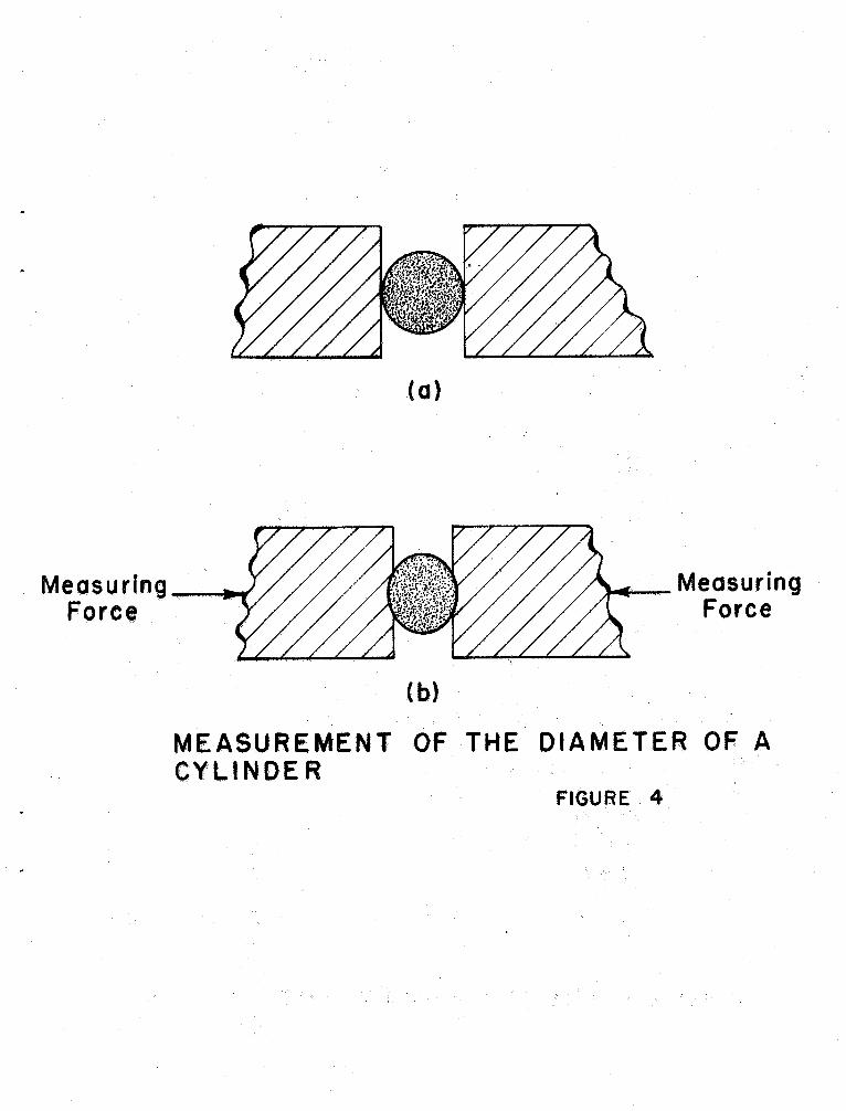
In the metrology field one fundamental measurement occurs frequently,
e., the measurement of the diameter of a cylinder. Figure 4a shows .
cross-section of the typical measurement between plane parallel anvils
of a measuring machine. Since it is infinit~ly difficult to measure the
object with zero force applied , Figure 4b shows the exaggerated resultant
shape of the anvi 1s and cylinder after a measuring force is applied. Since
the customer usually desires to know the lIunsquashed" diameter , certain
corrections must be applied to account for the measurement process.
To solve this problem we shall make use of the expressions already
deve loped to solve for the "pressure distribution" and size of the area
of contact by allowing one axis of the ellipse of contact to become infinite.To determine the deformation, the contact area will be taken as being a
finite rectangle wit:h one side very much greater than the other.
The derivation will be for the case of a pair of cylinders with their
axes parallel and is based on the works of Thomas and Hoersch (7J, and
Love (8J. The solution for a cylinder to plane contact can easily be
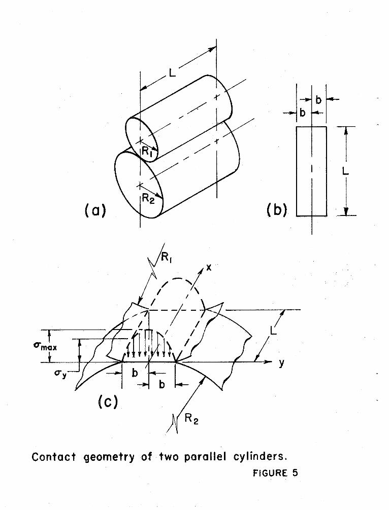
obtained by allowing the radius of one of the cylinders to become infinite.Line contact occurs when two cylinders rest on each other with their
axes parallel (figure Sa), and when a cylinder rests on a plane. As the
two cylinders are pressed together along their axes , the resulting pressure
area is a narrow " rectangle " of width 2b and length L (assuming no taper
in the cylinders). In other words , the area of contact is an elongated
ellipse with the major axis of the ellipse equal to L and the eccentricity
a ppr oachi ng uni ty .
The distribution of compressive stress a long the width 2b of the surface
of contact is represented by a semi-ellipse (figure Sc). The stress
-17-
distribution over the ellipse of contact for the three-dimensional case
wi 11 be remembered from Equation 12 as
p("
~:b 1 . :L.....
where a(x represents the stress acting at any point (x
Now the integrated pressure over the surface of a finite rectangle
across the minor axis of the ellipse in the plane x = 0 (figure Sc), is
p =
a (0
f1 -
y.!!:..)
1/1 d. '2TIab b 2
..1L 2nab 2 - (40)
Now as a 4 00, let P - 00 in a manner so that pia remains equal to a finite
constant. Then the va lue of P is the force per unit length of the contact
area. For a = 00 , the compressive stress at any point is given by,
3P 2 1/2
a(y) = 2nab (1 - ~) (41)
and by substitution of Equation 40 .into Equation 41 we obtain, since
P = pIL 2P 2 1/2
a(y) = nLb (1 - ~) (42)
We can now see that the maximum value for the stress within the area
of contact will be at the center where = 0 and is
a =-max TILb(43)
-18-
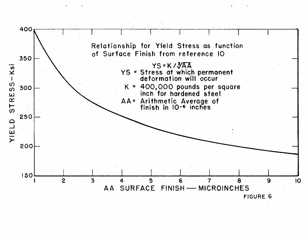
The maximum compressive stress is important in anycont~ct problem
because the surface area of contact is small and very high stresseS may
easily be obtained with relatively light loads. If
(j
exceeds themax
microplastic yield point of the material, then permanent deformation
will occur. A relationship for hardened steet" relating yield stress to
surface finish is shown in Figure
We now need to develop ~n expression for the width of contact b , and
by knowing b , the stress at any point can be computed. The surface of
each cylinder may be represented by the equations,
l = B 1 Y
2 = B2 Y
From Equation 20 and using the expression developed in Equation 40
we obtain
B = (A. + A. ) 'J:'
2 L 0 (b
2 + 'J:') ((a2 + 'J:')'J:')(44)
and since the one axis of the ellipse , a -+ 00, the expression becomes
'00'J:'B - ("-1 + "- ) L 3/2 1/2
(b + '.l') '.l'
(45)
By using the expression in Equation 42 , Thomas and Hoersch evaluated the
above equation to give
B = 2 (A.I + "- ) plLb or
2 ("- 1 + "- (46)
where b is the half-width of contact,
P is the tota 1 force
L is the contact length.
-19-
For a pair of cylinders with their axes parallel and radii r1 and r
respectively, we have
l = B 2r 1
2 = B
Thus1 + r
B = Bl + B2 - 2r 1 r
2 = 4("-1 4- A.
)P(rL(r 1 + r
(47)
For a cylinder on a plane surface
Z =
z =-=0
thus
4r ("-1 + "-
) p
(48)
Now since our cylindrica 1 surfaces are described by By forms, we obtain
from Equation 8,
where r = ((Y
(A. + A.
p(y
l = 6 - By
- y
2 +x 1/2 and the integral applies to the flnite
(49)
rectangle of contact with one side (L) very much longer than the other (2b).
We now have
-I-b. 2
P(y , ) ~(O
, y) :::
. 2 2 1 dx dy
((y - y
) + X l )
-b -L
-20-
~p(y ' , ((y -
-b . I~p(y'
) In
(~+ ((y
;/?;.t (P~
I/~
If We assume ('2) is
very large in relation to
(y - y
) then,
y '
) 2 + x I 2) 1dx '
and
0(0
, y)
~J-H,2P(Y In (
y -
) dy (50)
0(0 , 0) ~ 2P(Y ~n
~.)
(51)
Let us pause a moment to recap what we are doing. Equation 49 gives
us the relation between the total deformation 0 to the potential forpoints within the contact area. Since we are interested in the maximum
deformation which occurs, we need to evaluate the integral in Equation 49
at the center line or where y = Thus , Equation 51 represents that
maximum potentia
Continuing, we may rewri te Equation 51 as
Ho, 0) ~ 2 In L fp(Y )dy . . (pey' ) In(y ) dy-b Since the force per unit lengtl?-.
f = frb
p(y '
)dy I and from Equation 41
may substitute into Equation 52 to obtain,
(52)
ip (0, 0) = 2 f tn L "1J t2
tn(y, )4Y (53)
To evaluate the integral in the above relationship, we make the substitu-
tion ; = Sin e and then dy = b cos e d e to obtain,
-21- .
tTT'll - ie)
V 2 (In 0. sin 2e))(~"o.e) de
-rr/2
~ ),
coo e (10(O .10 e)) de
12TI/2 b(21nb)r CDie de + Zbr coa e Inlsinelde/2 -TI/2 ..
we know that,.,
l2
cos e de =
TI/2and the integral
+rr/2 I = . cos e 1n Isine deTI 12
has been evaluated by Birens de Haan (9J, to give
I = (1 + 1n4)
So we obtain the value for the total integral as
= b 21nb 11. + 2b
11. - !!. In4- 2 1n4
= TIb (lnb - -
--)
Thus by substituting into Equation 53 we obtain
0(0 0) . 2 t 1n L - (rtb (lnb (1 ; 1n4)
- 2 t (lnL - lob + 1 + 104
, 0) 2t (1"1 - 1nb + 1, 193145)
Since
6 = (A. + A. Fey2 . ' r
dx ' ' + By
22-
and if1 (0, 0) gives uS th~ potential at the center of pressure zone we have,
0 = ("-1 + "-) 2 L
(rnL - .1nb + 1. 193145)
as the total defo.rmation of a pair of cylinders with their axes parallel
or a cylinder on a flat surface. The value of. b (half-width of contact) is
substitute:l into equation 54 to obtain the appropriate answer for any
particular case.
Since equation 48 gives us the value of b as
b =(4r ("-
l : "-1/2
we have4r ("-1 + "- ) P
6 = ("-1 + "- ) 2 L 1nL - 2" 1n
+ 1.193145
= L ("-1 + "- (:l1n1 - 1n(
4'("+ 2. 38629J
= -
(Ae + "- ) 21nL + In + 2. 386294r ("-1 + "-
) p
0 = L ("-1 + "- (1~ 4(/"
\ /..
) + 2.38629) (54)
where P = total measuring force
= length of contact between plane and cy1id
i = 1 - v I ITIE
= radius of cylinder
= total deformation of cylinder and plane.
Another form of Equation 54 can be obtained by not evaluating the
term (1 + 2 ln4 which gives
-23-
::;: L (/..1 + "- (1.00 + I.
I ;1,. ) Pr
(55)
Remember this formula is for th~ case of a cylinder to plane on only one
side. If both sides are desired , such as the case in Figure 4, then
::;: 20
If the lengths of the lines of contact are not equa 1 or if the ma teria 1
of either cylinder or plane are different, then the total deformation
will be
T = 0 1 + 6
A similar approach for the computation of the deformation of a
cylinder to plane has been obtained from correspondence with Bob Fergusson (1OJ.
The basis of the work is a paper by Airey C llJin which formulae are given
for the solutions of elliptic integrals when the eccentricity (e) approaches
unity.
From Equations 4 and 5 we have
1 1A + B ::::0---. +
, + - + -
1 D1 D2 D
..l 1...
,) (
1... cos 2UJA)
::;:
1 D
where a il. are the two principa 1 diameters body
and are the two principa 1 diameters body
Iii the case cylinder plane, body the cylinder aad body
is the plane , then
::;:
Diameter of cy1inde~
D ' ::;: 00
24-
2 = ~ if the plane is truly a flat surface
D '
= ~
Since we have shown for the case of a cylinder to plane
B=-"'-l D
Thus the parameter ~ = --- = AD
From the previous Equation 38, we knOW"
A -
where E is the complete elliptic integral of the second kind
K is the complete elliptic integral of the first kind
e is the eccentricity of the "ellipse" of contact which approaches unityIn Airey s work Ill), expressions were given for evaluation of the
elliptic integrals when the eccentricity approaches one , viz
where
K (e 2) = In ~. K - Vh K(e ) = complete elliptic integral of first kind
= square of modulus e
(56)
h = square of the complementary modulus or (1 - e )
~ 1 2 . 3
l = 11 + . h + 2
2 . 42 . h +
2 = J
~~
- i). h +
:~ (i). h
2 +
. . .
and E(e ) = In
~.
E + Vh (57)
where E (e ) = complete elliptic integral of second kind
0: ~ _1 . h + 2 . 3
2 +
. 2
. .
Z = j
~ -
- ~). h -
~~ : :
(i - ). h
Z - .
. .!
25-
Thus as e ..... 1
k(e ) = In 4(1 - e
(58)
From Equation 37 and using Airey I s expressions when e--1
IK+ dE -
e(l - e
which reduces to
dK dE = (59)
and
p:. -
h B(60)
Since from previous derivations , namely Eq.. 32 where
A a3 = ~p ('\1 +'\
) (~)(-~)
We substitute (6) into the above to obtain
A a3 = ~p (A.l + A
) (*~)
and
A a = IP (~ + ~) h (AD
3 PD= 2 (A1 + A
3 PDh = 2 (AI + ~) 3""
Now since a = 2 (the ellipse of contact approach where the major axis of the
ellipse is a) we have
h = 12 (\ + A 2 L
-Z6-
From Equation 34
8a = 2'P 0' 1 + ~ ) (K)
3 P = '2 a (~l + ~) ;Jh
Since 1n = '2 In 16 - '2 1n h = '2 1n
3 P 16 L3 j
8 = '2 ;: (1\ 1 + '\ '2 In 1Z(A )PD)j
and since a = L/2
4 L8 = '2 (A
1 + A ) I 1n3(Ar + A )PD
4 L
(61)
8 = 1. (.\ + A ) 1.02 L 3(\ + A )PD
since D = Zr
= 1. (.\ +
.\)
In 4 L
..
2 L 3(2)(A1 + AZ)pr
4 LIn 6(\ +.\
)pr = In '6 + 1.0 (.\1 + .\
In % = 1n 4 - In 6 = 1.386Z9 - 1.79176
... -
40547
8 = ~ (Al + ~)t: t . 40547 + In
L 1
Az)~
~ ~ (~
+Az) f
(. .
60S205 + 1. 5 In (~ f 9~,:J(62)
This expression is for the contact case of one side of the cylinder pressed
-27-
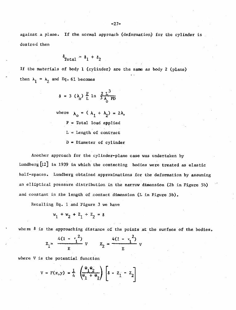
against a plane. If the normal approach (deformation) for the cylinder is
des ire d then
Total = 8 1 + 8
If the materials of body 1 (cylinder) are the same as body 2 (plane)
then Xl = X2 and Eq. 61 becomes
2 L 38 = 3 ().) L 1n 3 A. PD
where ).0 = ( ).1 + ~) = 2).P = Total load applied
L = Length of contract
D = Diameter of cylinder
Another approach for the cylinder-plane case was undertaken by
Lundberg ~2J in 1939 in which the contacting bodies were treated as elastic
half-spaces. Lundberg obtained approximations for the deformation by assuming
an elliptical pressure distribution in the narrow dimension (2b in Figure 5b)
and constant in the length of contact dimension (L in Figure 5b).
Recalling Eq. 1 and Figure 3 we have
1 + w2 + Zl + Z2 = 8
whe re 8 is the approach ing dis tance of the points at the surface of the bodies.
4(1 4(1 J' )Z '-
where V is the potential function
v = F(xy) = t
(~:t:\(8 - Zt .
-28-
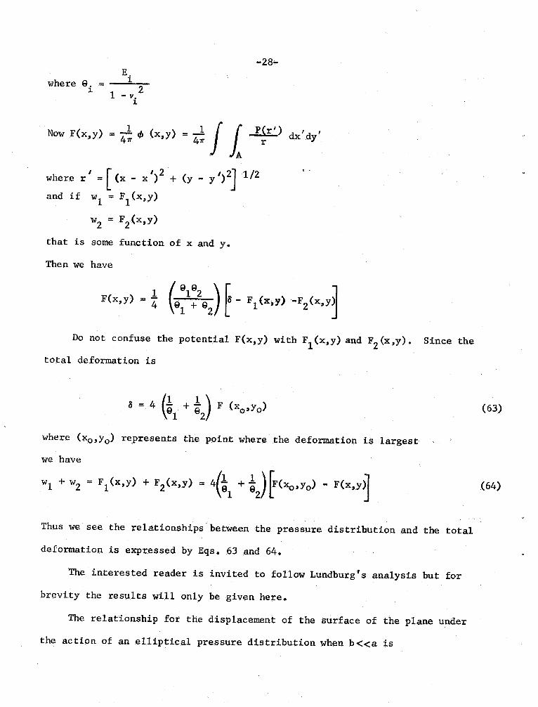
where 9. =
~ 21 -
Now F(x
, y) ~
i; '" (x,y) = i;
) d,, ' dy
l/2where r (x - x)
+ (y - y )
and if wI = F1 (x
,y)
2 = F 2 (x
,y)
that is some function of x and y.
Then we have
f(x
, y) =
~:~ 9 )r. t (x,y) -~ (x
, y~
Do not confuse the potential F(x,y) with Fl (x,y) and F2 (x ,
y).
total deformation is
Since the
8 = 4 (tl +
F (x (63)
where (xo'Yo ) represents the point where the deformation is largest
we have
1 + "2 = Fl (x,y) + F (x,y) = 4(~1 + *Jr("",
) - F(X'Y~ (64)
Thus we see the relationships between the pressure distribution and the total
deformation is expressed by Eqs. 63 and 64.
The interested reader is invited to folloW' Lundburg I S analysis but for
brevity the results will only be given here.
The relationship for the displacement of the surface of the plane under
the action of an elliptical pressure distribution when b"::::..::::a
-29-
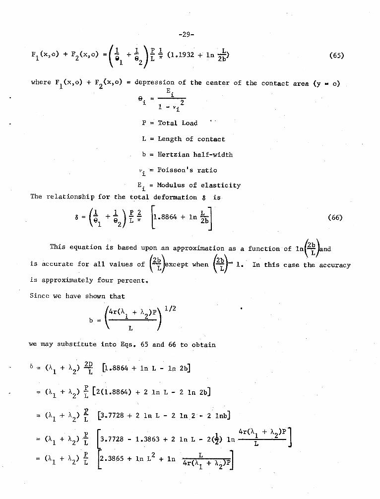
l (x o) + FlX, o) = (t1 + ~ )f ~ (1.
1932 + In (65)
where F1 (x
o) + F 0) = depression of the center of the contact area
(y
- 0)
e. = L 2
1 - v
P = Total Load
::: Length of contac t
b = Hertzian half-width
1'. = Poisson s ratio
E. = Modulus of elasticityThe relationship for the total deformation 8
8 = 1 +
! ~
L rr 8864 + in ~bJ
This equation is based upon an approximation as a
is accurate for all values of )excePt when ~ 1.
is approximately four percent.
Since we have shown that
4r(1.. + A 1/2
b =
we may substitute into Eqs. 65 and 66 to obtain
0 = (A + A (1. 88.64 + In L - 1n 2bJ
= (1..1 + 1.. ) t (2(1.8864) + 2 In L - 2 1n 2bJ
= (1..1 + 1.. ) L (3. 7728 + 2 1n L - 2 In 2 - 2 1nb)
(66)
function of 1n(~)and
In this case the accuracy
= (1..1 + 1.. ) L
= 0. 1 + 1.. ) L
I 4r(A.l + 1..7728 - 1.3863 + 2 1n L - 2(1) 10
3865 + in L2 + ln
4r(A~ + A )PJ
= (A1 + A ) L 3865 + In
OOO9 + In
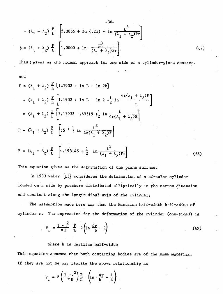
-30-
25) + in (A1 + A
)Pr
~ +
9pr (67)8 = (Ai + " ) L
This 8 gives uS the normal approach for one side of a cylinder-plane contact.
. .
and
F = ("1 + " ) f (1.1932 + 1.0 L ... ln 2b)p r. 4r("1 + "
= ("
l + " ) L ~. 1932 + 1n L - 1.0 2 ;2 1n L= ('r + A ) t (10
11932 - ~9315 +t In 4r(Ai + 91'
F = (1.1 + 1. ) f (:5
+!
4r(A.~ + A.
F = (" + A
) -
2 L 193145 + 2 1n ("1 + A
)pr (68)
This equation gives uS .the deformation of the plane surface.
In 1933 Weber (13) considered the deformation of a circular cylinder
loaded on aside by pressure distributed elliptically in the narroW' dimension
and constant along the longitudinal axis of the cylinder.
The assumption made here 'Was that the Hertzian half-width b ~~ radius of
cylinder r. The expression for the deformation of the cylinder (one-sided) is
v = l-v
1 n
& -
1/'E L (69)
where b is Hertzian half-width
This equation assumes that both contacting bodies are of the same material.
If they .are not we may rewrite the above relationship as
= 2 1 - \, ~n'-!fL 1c 1/'E
-31-
~1 ;t(
:~~
) I (In - t)
Now
1n -- = In 4 + 1nr- 1nb
4r(A1 + A
= 1n 4 + 1nr - 2' ln
1n 4 + 1nr + 2' ln 4r(A1 + A
. L= l. 38629 + 2' 1nr + 2
1.0 4r(A1 + A
= 1.38629 + 2' 1n 4(A + A )P
= 1. 38629 + 21n (8 25) + 2'ln (A + A)P4r In --. = 8 693l45 + _
1 +A
So we have
~ ~l + A ) t
Weber also obtained an expressed for the deformation of
(19314, + t 1n f ~)
F "
~)( +
2 in
~ )
Using the same logic as before in the case of the cylinder
- 2(1 ;E
)(f) (t + in
l - 1 1 - 1' l .F ~
';;
7:;' 2" + In ~bj
(70)
the plane surface as
(71)
-32-
In ...1 == 1n L ln7T - 1nb7I'b
1 4r(A1 + A== In L 1n7T - 2~n
== '2 1n L - 1n7T + 2 In 4r(A
1 + A
L 3== -ln7T
+ 2 1n 4r(A1 + A
= -1. 1447 + 2 1n (. 25) + '2 1n (AI + A
)Pr
== -1. 1447 - 693l5 . In
1 + 1\.2 Pr
In 1- == -1. 83787 + 11n L7Tb 2 (Al + A
)Pr
P ( == (A
l + A ) L C1.33787 + '2 1n (A
1 + A)Pr
To obtain the total deformation for the case of a cylinder between two
anvils we have
Total == 2(Vc + V
" Z ((A1 + A ) t (.193145 + t 1n
~ A.1.337~7
" 2 ((AI + 1, ) fr1. 14473 + 11n
I +)9
8 = 2 (0'1 + ' ) f(-lo14473 + In
L: X
+ t In ~F"
Various other relationships for deformation of circular cy1 inders have
been derived by Db'rr (14), FO'pp1 (15), Kovalsky (16) , and DinniK (17) .
the pertinent results will be given here.
D8rr calculated the displacement of the points of initial contact by
assuming a smooth circular cylinder of radius r was compressed between smooth
rigid" planes from the re lations hip
(72)
(73)
Only
-33-
2(1 - I' 2
==
7TE
one-sided(f) (In
~ -
where b == (4r (\ + 1..) t) 1/2
2(1 - vI )
7TE L 0 193145 + '2 In1 + A
(74)
Thus the change in diameter of the cylinder according to Dorr would be
== 28Total
According to Roark (18) a similar expression for the total compression of
of a cylinder between two rigid planes was derived by Foppl. It is
Total " 4 ( ) f (1 + lnwhere b is Hertzian half-width
1 - P r LR one-side . Z .E Z t ( 3333 -Ie '2 1-n
(\ + '
)1'(75)
Roark also gives an expression for the mutual approach of remoted points in
two plates as
1 - 1rEL== 4 7TE . L P(l
(76)
When a cylinder is compressed between two parallel planes.
Kovalsky, in 1940 , derived an expression for the deformation of a circular
cylinder of finite length loaded from two sides by pressure distributed
elliptically across the contact width. The change in diameter parallel to the
direction of the force was
Tot4(1 -
7I"E
-34-2r In b + 0.407 (77)
Again \I = Poisson ratio for the cylinder
E = Modulus of elasticity for cylinder
. .
P = Total load
L = Length of contact
r = Radius of cylinder
b = Hertzian half width
Dinnik also calculated the change in diameter of a circular cylinder but
by assuming the pressure distribution across the contact width was parabolic
in nature. His expression was
= 4
- '0Tot 7I"E L (In
+ ~J(78)
Since Lundberg calculated the displacement of the surface of an elastic
half-space under the action of an elliptical pressure distribution from the
relation
. - 2 :t? (1.1932 + In
where ~ = depression at the center of pressure zone.
We may write the normal approach of a distant point in the elastic plane to
the axis of the cylinder as the sum
where.1. 8 +
TotAnother relationship was obtained from a Canadian report which gives the
compression at the point of contact of a cylinder and a plane as
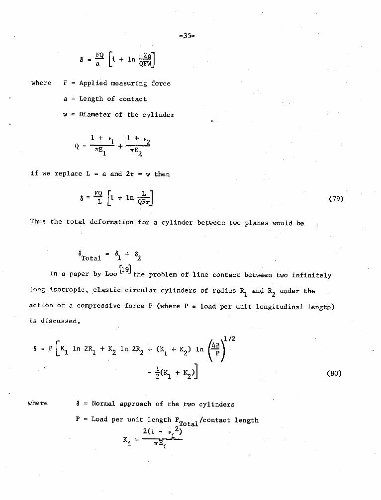
-35-
8 ;: (1 + 1n
where F = Appl ied measuring force
a = Length of contact
w = Diameter of the cylinder
1 + l' 1 +
= 7I"El 7I"E
if we replace L = a and 2r = 'W then
8 = .E.Q 1 + 1 QFr (79)
Thus the total deformation for a cylinder between two planes would be
= 8 + Total In a paper by Loo
(19) the problem of line contact between two infinitely
long isotropic , elastic circular cylinders of radius and R2 under the
action of a compressive force P (where P :: load per unit longitudinal length)
is discussed.
1/28 . P
(~
In 2RI + 111 In 2R2 + (Kl + K ) In
.. t(K1 + K (80)
where 8 = Normal approach of the two cy1 inders
P = Load per unit length PTota1 1contact length
2(1 - 1,K. = 7I"E.
-36-
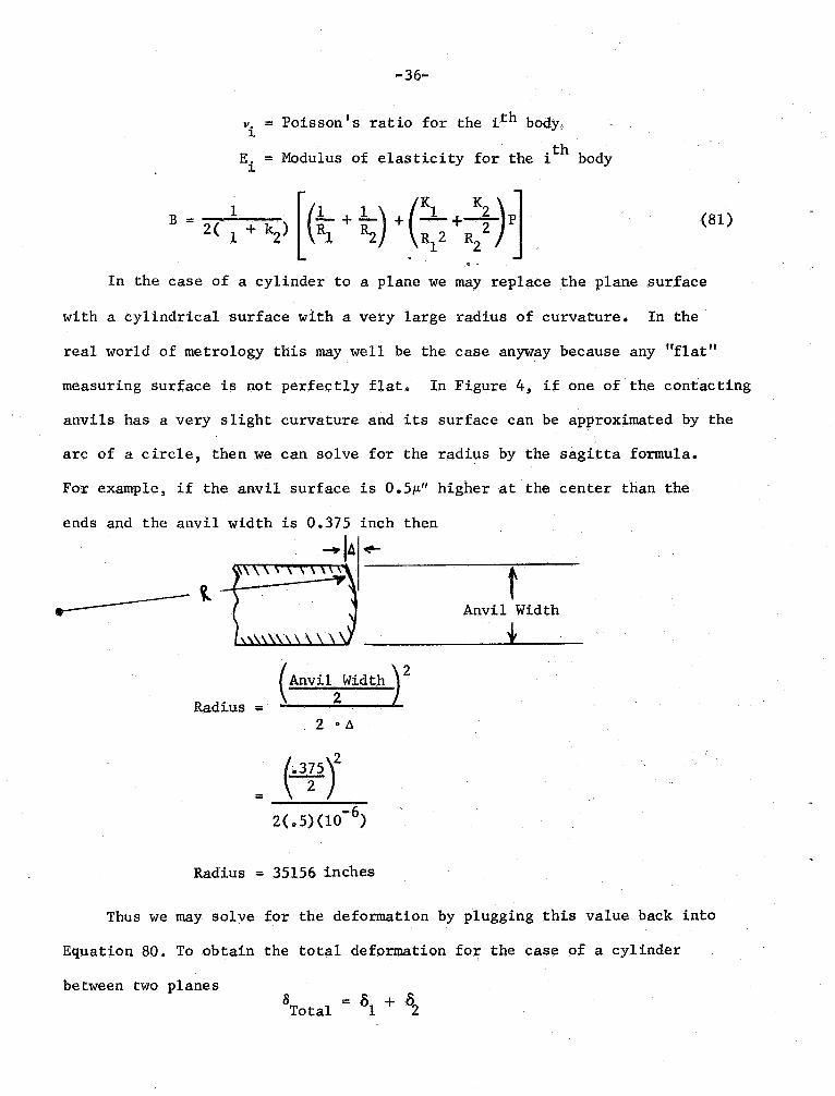
v. = Poisson s ratio for the i th body,
i = Modulus of elasticity for the ~ 0 y
1 + 1 + z.\p~J
In the case of a cylinder to a plane we may replace the plane surface
2(" +(81)
with a cylindrical surface with a very large radius of curvature. In the
real world of metrology this may well be the case anyway because any "flatmeasuring surface is not perfec tly flat. In Figure 4, if one of the contac ting
anvils has a very s light curvature and its surface can be approximated by the
arc of a circle , then we can solve for the radius by the sagitta formula.
For example , if the anvil surface is 5p. higher at the center than the
ends and the anvil width is 0. 375 inch then
.......jA .,....
----
Anvil Width
( Anvil Width
Radius =z .
(~y
2(0 5)(10
Radius = 35156 inches
Thus we may solve for the deformation by plugging this value back into
Equation 80. To obtain the total deformation for the case of a cylinder
between two planesTota1 = Sl + S
..37-
EXPERIMENTAL VERIFICATION
Since the validity of any theoretical formulation is dependent upon experi-
mental verification, we have performed a literature search for verification of
the formula describing the deformation of a cylinder between two planes
Bochman (20J performed his dissentation on this subject along wi th measurement
of the deformation of steel balls. He began by assuming the ob1ateness of a
cylinder between two planes increases in proportion to the load and is
influenced by the size of the measuring surfaces. An elaborate lever system
was devised for amplifying the deformation and a Zeiss optimeter was used as
the readout device. The c.ontacting anvils were hardened and finished to
end-s tandard qual i ty
" .
The optimeter was calibrated with end standards but
could only be estimated to 1;u (4p.") with a measuring accuracy of approximately
2p. (8p.
")
The cylinders used in the test 'Were steel wires (used tome.asure
the pitch diameter of external threads) with nominal diameter 0. 18mm to 50 7Ommo
The applied load varied from 1 Kg to 10 Kg in some cases Anvil pairs used
were 5. , 8. 03, and 14095mm in 1engtho
The contac t case where the wires were shorter than the measuring surfaces
was also examined. The test results proved that the length of the wire exceeding
the size of the measuring surface has no effect on the amount of deformationo
In other words it is immaterial whether the length of the wire exc~eds that of
the measuring anvil or whether the measuring anvil is larger.
The values for ob1ateness for the 1 Kg load were plotted against the cube
root of the curvature (reciprocal cylinder radius) with the result being linear..
Thus he concluded the proportionality equation was
- 3 P 3t:'T,..M = C x 10 v1/D mm (82)
-38-
where M = ob1ateness in mm
C = Constant of proportion~lity
P = App1 ied load in Kg
L = Contac t length in II1Il1 .
D = Cylinder diameter in mm
The factor C was determined as 0.9228 from 35 test series. The mean
error of the individual value of C was + 1.99% and the maximum deviations from
the mean were + 3. 6% and - 5. 1%.
By rewriting the equation we obtain
20 = 0.2207 L -1/3 microinches
where 20 = ob1ateness in micro inches (10-6 inches) of a
steel cylinder when compressed between two flat
steel planes
P = Measuring force in pounds
L = Contac t length in inches
D = Cylinder diameter in inches
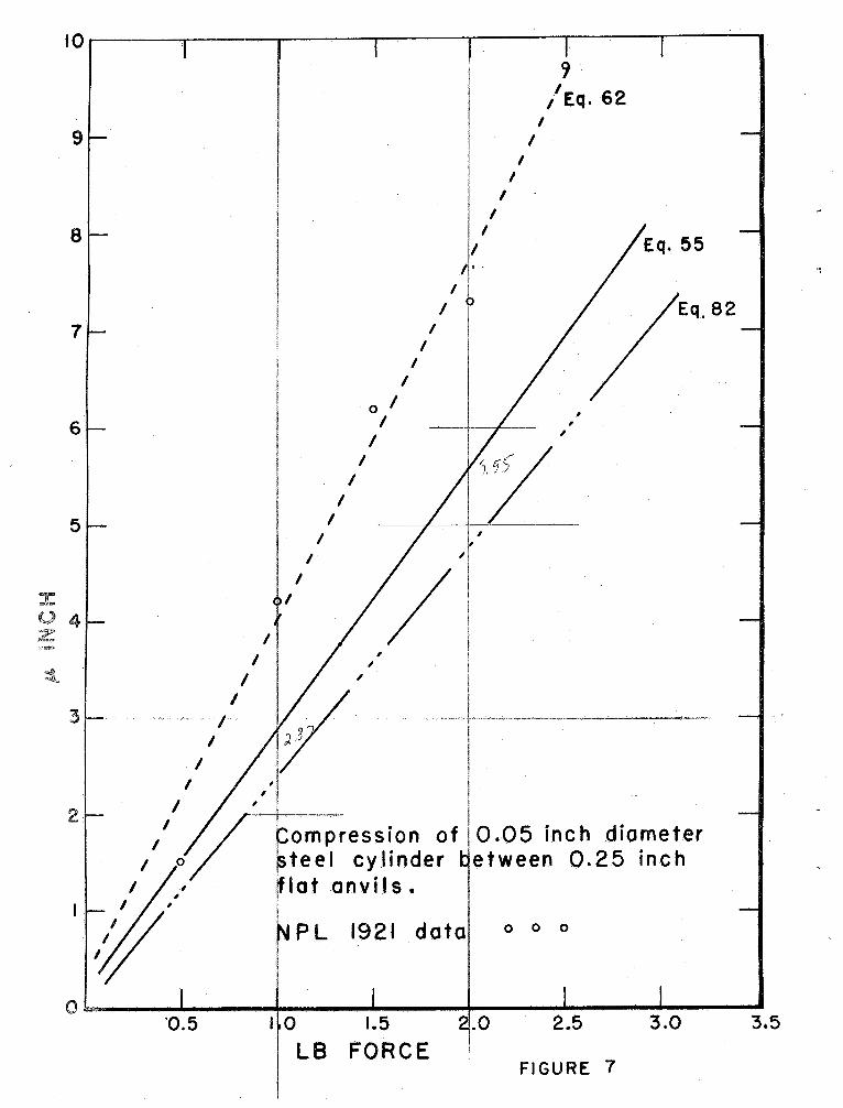
In a 1921 report by the National Physical Laboratory a test was conducted
on the compression of a 0.05 inch steel cylinder between a pair of flat.
measuring anvils 0.25 inch in diameter. The resu1 ts of that experiment are
shown in Figure 7 along with the results of Equations 55 62 and 82 from this
paper. There is no mention o.f the uncertainty in the NPL experiments.
see from Figure 7 that the data from NPL agrees quite closely with Equation 62..
In a more recent study of line contact deformation by Fergusson C6J the
-39-
resu1 ts of a series of tests on hardenec;l steel rollers between parallel plates
was discussed. From Equation 61 the equation for two bodies of the same
material tiB = 3(A
) f In 3A PD
Thus the total deformation for the case of a cylinder between two planes would be
Tota1 = 2B
From communication with Fergusson a number of tests were performed and
an empirical relationship was found which agreed within 7% of those values
given by the theoretical equation above for values of force from .2 1b to
16 lb, values of diameter . 01 inch to 10 inch, and values of L from 001 to
1 inch. The relation is
B = 0. 00534 L-0. 765 D-0. 053 p 94 (10
) inch (83)
where B = Deformation
L = Contact length in inches
D = Cy1 inder diameter
p = Total force in Ibs
Again the total de format ion would be 2 B .
The experimental results for a 1.0 inch cylinder between flat , parallel
planes 0. 118 inch in width were summarized by still another empirical formulao
B = 0.0091 L-0. 73 D-Oo08 p 6666 (10 ) inch (84)
Many factors have an effect upon the deformation in a cylinder to plane
case such as the type of surface finish and the parallelism of the plane
surfaces.
40-
In the most recent measurements on the compression of a roller between
parallel planes Thwaite (21) devised an apparatus consisting of a cylindrical
shaft with an air bearing for loading coupled with capacitance probes to sense
the compressi.on. The test cylinder and flat were made of Cr - Mn hardened
tool steeL The plane was flat within 0. 025llm (Ill ) and the cylinder was
" .
straight to 0.025llm. Both plane and cylinder possessed a surface roughness
of O. Olllm 4ll center line average.
The entire system possessed a resolution of 0. 003llm 12ll Three series
of measurements were made on a 6. 35mm diameter cylinder in contact over a length
of 9. 525mm for the load/contact length range of 0.05 to 0. 4 Kg/mm. The mean
observed slope differed by approximately 5% from the equation based on the
finite rectangle , that is Equation 55
215 ~ L (AI + A
. 1. 0 + In
I + A)pr
while the values predicted by the Bochman and Berndt (20) relationship differ
from Thwaite ' s slope by 45%.
Thwaite concludes that within the load range tested the equation based on
the finite rectangle gives the b~st approximation to compute the compression
involved in the case of a cylinder between two planes. That is, the finite
rectangle relation seems to be the one that would be of more practical use in
the metrology field.
CONCLUSIONS
Since the contacting case of a cylinder between two planes has such
widespread application in the science of metrology one needs to be able to
apply elastic corrections for the most precise determination of a diameter of the
cylinder. There are many prediction foDnulae depending upon the assumptions made.
-41-
This paper has assembled the majori tyof the equations in existence in theliterature and a master computer program was written to evaluate their
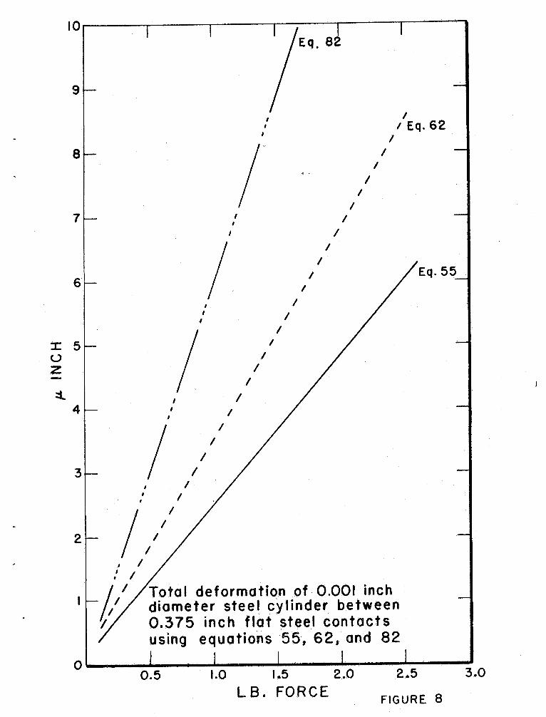
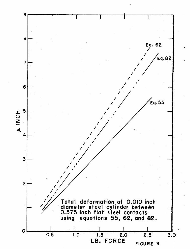
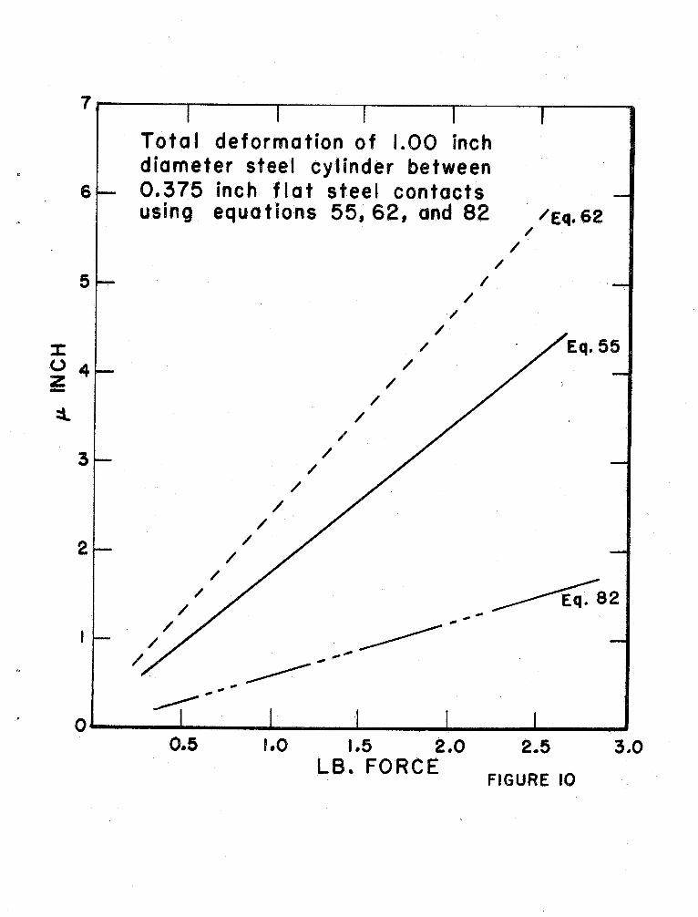
agreement over the range normally used in precision metrology. Figures 8
and 10 give the results of three equations 62 55 and 82 which are representative
of the three basic types of cylinder-plane equations discussed on page 4.
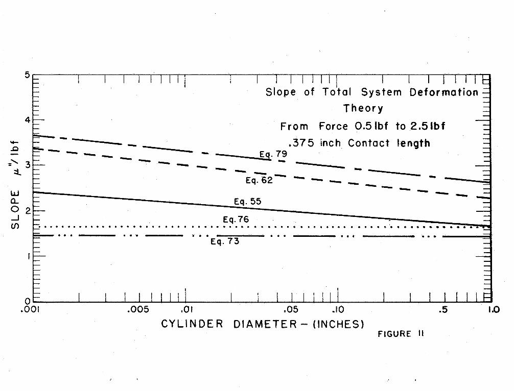
Eight of the equations were evaluated over the range 0. 5 - 2. 5 1b forc~
and cylinder diameter varying from . 001 to 1. 00 inch. The slopes (micro-
inches lIb) of five theoretical equations are plotted in Figure 11. The slopes
of three empirical equations over the same range are shown in Figure 12. 'ro
obtain the deformation for anyone equation
a) Find the diameter of the cylinder
b) Read the corresponding slope from the vertical axis , and
c) Multiply that slope by the measuring force in pounds to obtain the
total deformation.
Note: Keep in mind that these slopes are for the total deformation of a
cylinder between two plane surface. For example the values are
twice the values given by the equations listed. Also the values for
Poisson I S ratio and Young ' s Modulus are for 52100 bearing steel
in which
= 0.295 and E = 29. 0 x 106 psi.
The length of contact between cylinder and plane is 0. 375 inches
in all cas.es.
One importan t fact to remember in all contact problems is to keep the
measuring force less than that force which will cause permanent deformation to
the objec t under test. For the case of a cylinder against a plan~ a
nomograph has been developed for easy computation of the stress (Figure 13).
-42-
In certain cases where the compression needs to be known to better than
5% then the only practical way to account for surface finish, the actual
material parameters , and the exact geometry of the cylinder and flat would be
to determine the compression experimentally. For the load range normally
. .
used in the metrology field it appears that Equation 55 , based on the finite-
rectangle approach, gives the best approximation to the compression obtained
between a cylinder and flat (Figure 14).
On a practical basis, since most line compress ion is small an error of
10 - 30% is not enough to give one insomnia because the measurement uncertainty
(standard deviation) ~il1 likely be the same order of magnitude if not larger
than the actual deformation of the system.
SUMMARY OF EQUATIONS
b = Hertzian half-width of contact
~R(\ + Ab = . Equations for Compression of Cylinder and Plane in Contact
(55) . r .
~ =
L 0' 1 + A ) L1.00 + ln (A
1 + A)PR
~ =
I + A
- .
608205 + 1. 5 1n
(!.
. ~ 3
. )PR
1 + " 1 + '. 1 + ~1 1 +
~ = -
00 + 1n PR
1 7T2 7T 1 7T
(62)
(79)
Empirical (Steel Cy1inder--Steel Flat)
(82)2 ~
(83) 8
-1/3 = 0.2207 L D (10 ) inches
= 0. 00534 L 765 D 053
p .
940 (10) inches
= 0. 0091 L 73 D 08 p 6666 (10) inches(84) ~
-43-
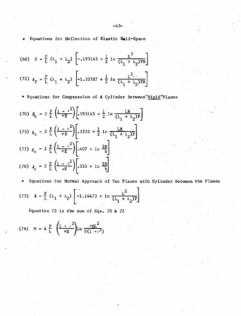
Equations for Deflec tion of Elastic Half-Space
F . t (AI + 1.
) ~ .
193145 + t In f\)PR
(72) 8p * t (A1 + A
) t1.33787 + t 1n
1 ~\)PRJ
(68)
. Equations for Compression of A Cylinder Between Rigid"Planes
1 - 1 ' (70) S = 2 L
1TE 193145
+ 2 1n (11.
1 + A
1 - LIt(75) S = 2 L.
1TE3333
+ 2
1n (AI + A
1 -
(77) 8 = 2 1TE
. .
407 + In
1 - v(78) at = 2 L
333 + in
Equations for Normal Approach of Two Planes with Cylinder Between the Planes
(73) . = L (1.1 + 1. . -1. 14473 + 1n
(1.1 +A
Equation 73 is the sum of Eqs. 70 " 72
1 - I' 1TEL(76) M = 4 L
1TEIn
P(l _
(tOJ
(113
1123
(13J
-44-
REFERENCES
Uber die :Beruhrung fester e1astischer Kerper , 188l; UberHe Hertz:
die Beriihrung fester elastischer Korper und uber die Harte , 1882,
English translations in He Hertz
, "
Miscellaneous Papers " pp 146-183
Macmillan , New York, 1896e
" .
(23
l3J
(4J
J. Prescott: Applied Elasticity , Dover, New York, 1961.
o. D. Kellogg: Foundations of Potential Theory Murray, New York, 1929.
Mary L. Boas: Mathematical Methods in the Physical Sciences . John Wiley
& Sons , Inc. , New York, 1966.
C 53 C. Hastings , Jr. Approximations for Digital Computers , Princeton Univ.
Press , New Jersey, 1955.
( 63 Bob Fergusson: Unpublished correspondence on deflection at point and line
contact , School of Engineering, University of Zambia.
(7 J H. R. Thomas and V. A. Hoersch: Stresses due to the pressure of one elastic
sol id upon another , Bulle.tin No. 212 Engineering Experiment Station, University
of Illinois , Urbana , Illinois.
(8J E. R. Love: Compression of elastic bodies in contact, Unpublished report
Defense Standards Laboratory, Australia.
(93 Nouvelles Tables d I Integra1es Definies. HafnerD. Bierens de Haan:
New York , 1957.
B. Fergusson: Elastic Deformation Effects in Precision Measurement
Microtecnic , Vol. 11, pp 256-258 , 1957.
J. A. Airey: Toroidal Functions and the Complete Elliptic Integrals,
Phil. Mag, p 177, Vol. 19 , No. 124 , Jan. 1935.
G. Lundberg: E1astische Beruhrung zweier Halbraume, Forschung auf dem
Gebiete des Ingenieurwesens , Vol. 10 , September 10ctober 1939 , pp 201-211.
Ce Weber: Beitrag zur Beriihrung gewo1bter Oberflachen beim ebenen
-45-
Formanderungszustand, Z. angew Math. u. Mech. , Vol. 13 , 1933 , pp 11-16.
(14J J. Dorr: Oberflachenverformungen und Randkrafte bein runden Rol1en
der Stahlbau , Vol. 24, pp 204-206 , 1955.
L15J A. Fopp1:
116J Kovalsky:
ische Mechanik, 1907.
Quoted in H. Rothbart Mechan~c:al Design and Systems Engineering
1964.
(17 J Dinnik: Quoted in H. Rothbart I Mechanical Desip;n and Systems Enp;ineering
1964.
(18J R. J. Roark: Formulas .for Stress and Strain, McGraw Hill , New York , 1965.
(l9J T. T. Loo: Effect of curvature on the Hertz Theory for Two circular cylinders
in contact , J.. Applied Mechanics , Vol. 25 , pp 122-124 , 1958
(20J I. H. Bochman: The Ob1ateness of Steel Balls and Cylinders due to Measuring
Pressure , Z. fUr Feinmechanik , Vol. 35, 1927.
(21J E. G. Thwaite: A Precise Measurement of the Compression of a Cylinder in
Contact with a Flat Surface , Journal of Scientific Instruments , (Journal
of Physics E), Series 2 , Volume 2 , pp 79-82, 1969.
(22 J T. F. Conry and A. Seireg: A Mathematical Programming Method for Design of
Elastic Bodies in Contact , Journal of Applied Mechanics , pp 387-392
June 1971.
(233 D. H. Cooper: Tables of Hertzian Contact-Stress Coefficients , University of
Illinois , Technical Report R-387 , August 1968.
(24J H. Poritsky: Stresses and deflections bodies in contact with application
to contact .of gear'" and of locomotive wheels , Journal of Applied Mechanics
Vol. 17, pp 191-201 , 1950.
(25J P. R. Nayak: Surface Roughness Effects in Rolling Contact , Journal of
Applied Mechanics , pp 456-460 , June 1972.
L26J
(27J
(28J
(29J
L30J
(31 J
l3zJ
L33J
(34J
-46-
J. A. Greenwood: The Areaof Contact of Rough Surfaces and Flats , Journal
of Lubrication Technology, Trans. ASME, Vol. 89 , Series F , 1967 , pp 81-91.
S. Timoshenko and J. N. Goodier Theory of Elasticity, McGraw Hill
New York, 1951.
S. D . Ponomarev , V. L. Biderman , e t a1.: Material Strength Calculations in
Machinery Design , Vol. 2 , Mashgiz , Mosco;," 1958.
F. C. Yip and J. E. S. Venart: An Elastic Analysis of the deformation of
rough spheres , rough cylinders and rough annuli in contact , J. Phys. D:
App1. Phys. , 1971 , Vol. 4 , pp 1470-1486.
C. A. Moyer and H. R. Neifert: A First Order Solution for the Stress
Concentration Present at the End of Roller Contac~ ASLE Transactions 6
pp 324-336 , 1963.
J. P. Andrews: A Simple Approximate Theory of the Pressure between Two
Bodies in Contact , The Proceedings of the Physical Society, Vol. 43
Part 1 , No. 236 pp 1-7 , January 1, 1931.
C. F. Wang: Elastic Contact of a Strip Pressed between Two Cylinders
Journal of Applied Mechanics , pp 279-284 , June 1968.
J. Dundurs and M. Stippes: Role of Elastic Constants in Certain Contact
Problems , Journal of Applied Mechanics , pp 965-970 , December 1970.
W. A. Tuplin: Commonsense in Applied Mechanics , The Engineer , June 26, 1953.
r 35J, J. B. P. Williamson and R. T. Hunt:
(36J
(37 J
Asperity Persistence and the real
area of contact between rough surfaces , Proc. R. Soc. London, Vol. 327
pp 147-157 , 1972.
G. Berndt: Die APp1attun.g von Stahlkuge1n und zylindern durch den
Messdruck, (The Compression of Steel Spheres and Cylinders by Measurement
Pressure), Z. Instrumentenkunde, Vol. 48 , p. 422.
L. D. Landau and E. M. Lifshitz: Theory of Elasticity , Pergamon, London
1959.

(383
-47-
10 Yao Shtaerman: The Contact Problem of Elasticity Theory, Mosc.ow"
Leningrad , 19490
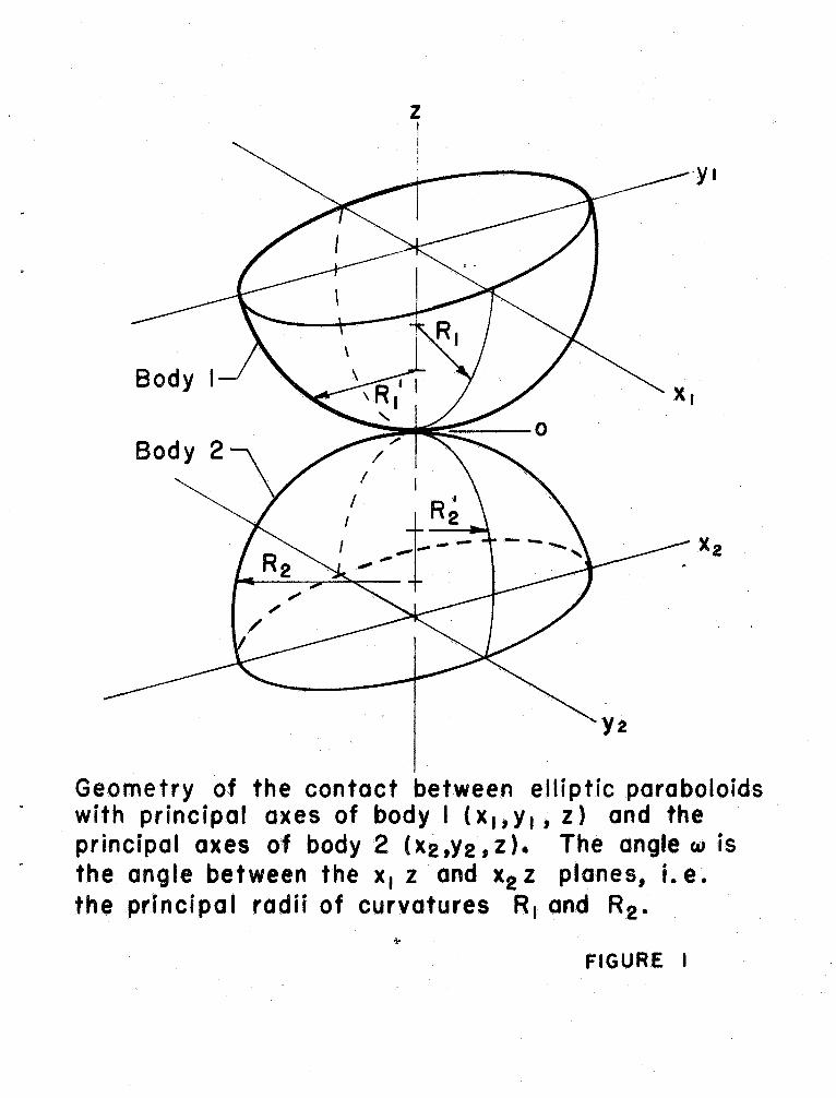
Geometry of the contact between elliptic pa.roboloidswith principal axes of body I ( x I, Y I , z) and theprincipal axes of body 2 (X2 ,Y2 , z). The angle wthe angle between the x, z and x2 z planes, i. e.the princi po I radii of curvatures R I and R2.
",.
FIGURE I
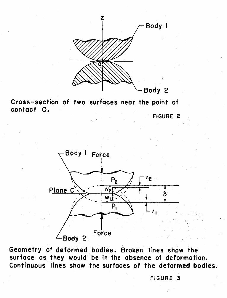
Body
Body 2
Cross -section of two surfaces nea.r the point ofcontact O.
Body I Force
FIGURE 2
ForceBody 2
Geometry of deformed bodies. Broken lines show thesurface as they would be in the absence of deformation.Continuous lines show the surfaces of the deformed bodies.
FIGURE 3
MeasuringForce
(a)
MeasuringForce
(b)
MEASUREMENT OF THE DIAMETER OF c..'l'LINDE R
FIGURE 4
max
(1' y
( a) (b)
Contact geometry of two parallel cylinders.
FIGURE 5
400
350t/)
300
a::
CJ)
..J
250
200
150
Relationship for Yield Stress as functionof Surface Finish from reference
YS=K/~YS = Stress at which permanent
deformation will occur':: 400, 000 pounds per square
inch for hardened s tee IAA = Arithmetic Average
finish in 10-6 inclies
AA SURFACE FINISH MICROINCHESFIGURE 6
/Eq. 62
/.
/ I
/ /
ompreSSion of 0,05 inch diameter~teel cylinder etween 0.25 inch~ I a n v it s .
:I:"." 4
::~t.
NPL 1921 data
I 0
LB FORCEFIGURE 7
::x: 5
IE 6 2
" /
Eq.
Total deformation of 0.001 i.nchdiameter steel cylinder between
37. inch flat steel contactsusing equations ' 55, 62, and
O 1.5 2.LB. FORCE
2..
FIGURE 8
::l.
Eq. 62
Total deformation of 0.010 inchdiameter steel cylinder between
375 inch flat steel contactsusing equations 55, 62. and 82",
5 '
FIGURE 9
1.0 5 2.LB. FORCE
:r:(.) 4
:::S...
Total deformati.on of LOO inchdiameter steel cylinder between
375 inch flat steel contactsusing equations 55, 62, and 82 /Eq.
Eq. 55
~82
. "---.... "'"........ ...
5 2.0 2.LB. FO RC E
FIGURE 10
- - - - - - - -
Eq. 62
- - - -
W -Eq. 55-I Eq.Cf)
. . . . . . . . . . . . . . . . . . . . . . . . . . . . . . . . . . . . . . . . . . . . . . . . . . . . . . . . ". . . . . . . . . . . . . .
Slope of Total System DeformationTheory
Fro m Force 0.5 Ibf to 2 .51b f
375 inch Contact lengthEq.
'+-
..c
::l
. . . . . . . . .
Eq.
. . . . . . . . .
001 005 .0 I . .10
CYLI NDE R DIAMETER - (INCHES)FIGURE II
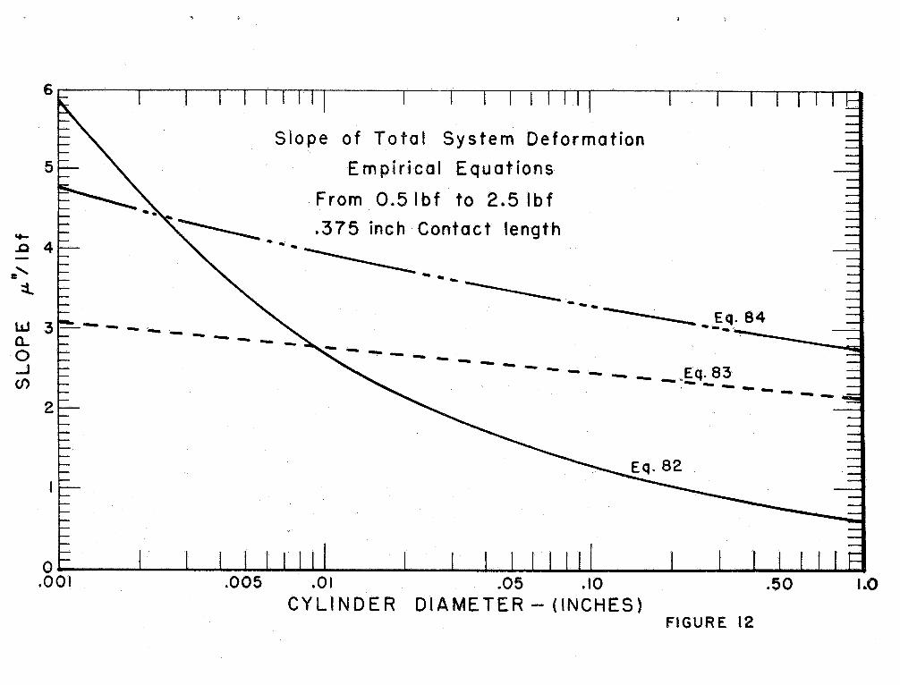
Slope of Total System DeformationEmpirical Equ at ions
From O.51bf to 2. 1bf
~ .
375 inch Contact length
- - - --------- - .. - --------.....
..Q 4
3 -
- - - - -
a.. -..J
(/)
- E q.
- - - - - - - - - - - - -
. Eq.
. - --- ---
00f 005 01 .05 .CYLINDER DIAMETER - (INCHES)
FIGUR E 12
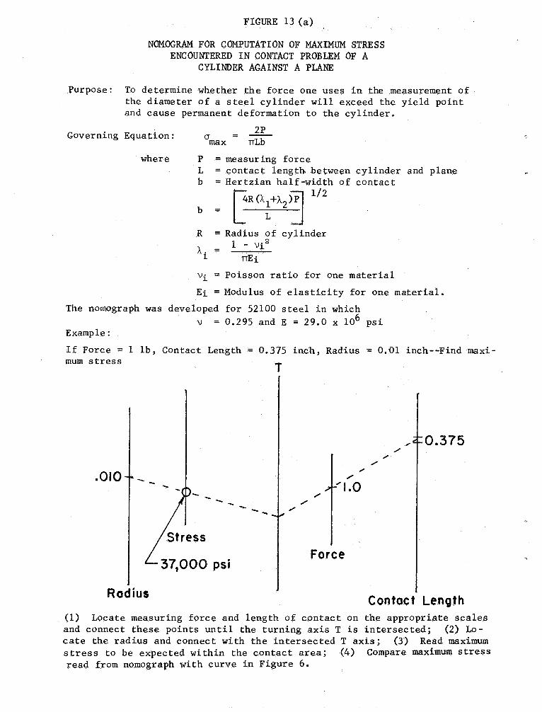
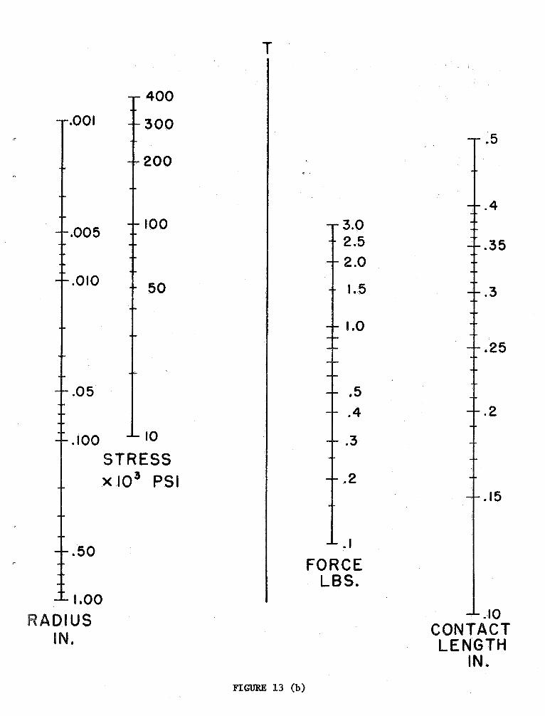
FIGURE 13 (a)
NOMOGRAM FOR COMPUTATION OF MAXIMUM STRESSENCOUNTERED IN CONTACT PROBLEM OF A
CYLINDER AGAINST A PLANE
Purpose: To determine whether the force one uses in the measurement ofthe diameter of a steel cylinder will exceed the yield pointand cause permanent deformation to the cylinder.
Governing Equa tion: max TILb
where = measur ing force
= contact length between= Hertzian half-width of
~R(A 1/2
= Radius of cylinder
1-.. = 1 - vi
TIEi
i = Poisson ratio for one material
cylinder and planecontac t
Ei = Modulus of elasticity for one material.
The nomograph was developed for 52100 steel in which
= 0. 295 and E = 29. 0 x 106 psiExample:
If Force = 1 lb, Contact Lengthmum stress
375 inch, Radius = 0. 01 inch--Find maxi-
...
375
010
...- -
Force
,.,
Rodiu.Contact Length
(1) Locate measuring force and length of contact on the appropriate scalesand connect these points until the turning axis T is intersected; (2) Lo-cate the radius and connect with the intersected T axis; (3) Read maximumstress to be expected wi thin the contact area; (4) Compare maximum stressread from nomograph with curve in Figure 6.
001
005
010
400
300
200
100
100 STRESSx 103 PSI
RADIUSIN.
FIGURE 13 (b)
FORCEL.BS.
1.5
1.0
CaNT ACTLENGTH
IN.
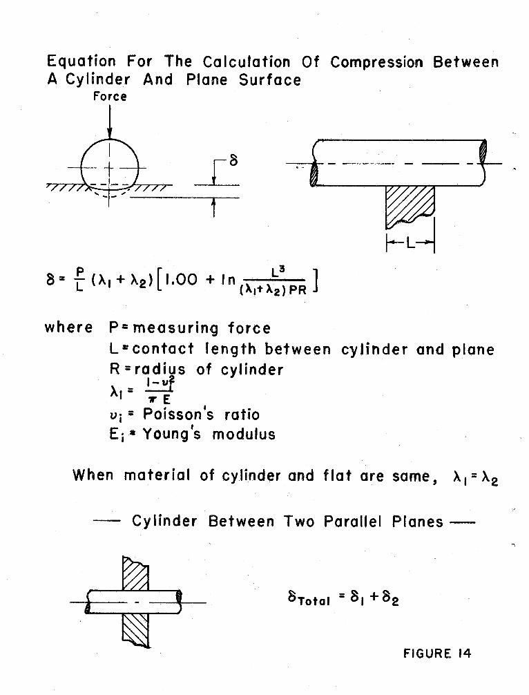
Equation For The Calculation Of Compression BetweenA Cylinder And Plane Surface
Force
L3
8 = L (X I + X 2 ) 1.00 + I n (). rt X2 ) P R
where P*= measurin9 forceL" contact length betweenR = radius of cylinder
I-u
...
Vi = Poisson ratio*' Young s modulus
cylinder and plane
When material of cylinder and flat are same , X, ::: X
Cylinder Between Two Parallel Planes
---
8Total = 8, +
FIGURE 14