on the analysis and design of in-wheel motor for vehicle
TRANSCRIPT

On the analysis and design of in-wheel
motor for vehicle application
Dissertation
zur Erlangung des akademischen Grades
Doktoringenieur
(Dr.-Ing.)
von M.Sc. Sergey Perekopskiy
geb. am 16.01.1988 in Makeevka, Donezka obl., Ukraine
genehmigt durch die Fakultät Maschinenbau
der Otto-von-Guericke Universität Magdeburg
Gutachter:
Prof. Dr.-Ing. Roland Kasper
Prof. Igor Gorobets
Promotionskolloquium am 18.09.2020

II
For my family
III
Abstract
The revolutionary changes in automotive industry which are based on the following trends in environmental
protection, lead to the new requirements that must be met in modern vehicles. Thus, for the automotive industry,
electric powered vehicles are becoming an increasingly relevant factor in the competition against climate change.
The expert community is united in the opinion that e-mobility is becoming the dominant factor in improving the
operating efficiency of vehicles. At the same time, the key aspects of changes in the context of the development
of vehicles represent directions that bring serious changes to the traditional automotive industry, especially in its
design and technological basis. One special example of a possible way of change represents an in-wheel motor
which provides a powerful and compact drive solution for electric vehicles.
The in-wheel motor as a modular element of an electric drive has long been known. In-wheel motors for a vehicle
have remarkable advantages as compactness and present a wide field of research for possible integration in vehicle
structures. Currently, the development of motor-in-wheeled electric transport drives is continuously increasing.
However, such a constructive solution for the vehicles could not be implemented until recently for a variety of
reasons. First of all, due to the impossibility of development of a compact, highly efficient drive that meets its
power and torque requirements. Therefore, the main disadvantage of the in-wheel motor is an unsprung weight.
This is why a usage of modern lightweight technologies in in-wheel motors is significant.
The purpose of this thesis is to present for the first time the findings and conclusions about the potential of the
novel in-wheel motor design with significant specific power and torque density for a vehicle with regard to
manufacturability and functionality. For this purpose, the design methodology of the in-wheel motor was
presented, which has an ambivalent manner. On the one hand the ascertainment of increased potentials for modern
lightweight technologies and materials according to their application on the in-wheel motor is applied to minimize
the total weight of the motor. On the other hand, an increase of the power and torque characteristics is realized by
the usage of new concept of the motor active parts – novel winding technique and arrangement of the magnets. In
addition, features such as functionality, stiffness and robustness have been considered due to the innovative
approach of specific load compensation in the in-wheel motor. Relevant research has demonstrated that integration
of the in-wheel motor in common vehicles together with a unique coupling element is soluble. The potentials of
the developed methodology were demonstrated by component and system testing of the completed prototypes.

IV
Kurzfassung
Die revolutionären Änderungen in der Automobilbranche, die auf den Tendenzen des Umweltschutzes beruhen,
führen zu den neuen Anforderungen, die in modernen Fahrzeugen erfüllt werden müssen. Für die
Automobilindustrie werden somit die elektrisch angetriebenen Fahrzeuge zu einem immer wichtigeren Faktor im
Wettbewerb gegen den Klimawandel. Die Experten sind sich in der Meinung einig, dass die Elektromobilität zu
einem dominierenden Faktor wird, da die Steigerung der Fahrzeugeffizienz somit gewährleistet ist. Gleichzeitig
stellen die Schwerpunkte der Veränderungen im Zusammenhang mit der Entwicklung von Fahrzeugen die neuen
Entwicklungsrichtungen dar, die gravierende Veränderungen für die traditionelle Automobilindustrie mit sich
bringen, insbesondere in Bezug auf Design und technologische Basis. Ein spezielles Beispiel der möglichen Art
und Weise von Veränderungen stellt ein Radnabenmotor dar, der eine leistungsstarke und kompakte
Antriebslösung für Elektrofahrzeuge bietet.
Der Radnabenmotor als modulares Element des Elektroantriebs ist schon lange bekannt. Radnabenmotoren für die
Fahrzeuge haben erhebliche Vorteile wie die Kompaktheit und stellen ein weites Forschungsfeld für eine mögliche
Integration in die Fahrzeugstruktur dar. Zurzeit nimmt die Entwicklung von elektrischen Radnabenantrieben
kontinuierlich zu. Allerdings war es bis vor kurzem aus einer Vielzahl von Gründen nicht möglich, eine solche
konstruktive Lösung für die Fahrzeuge einzusetzen. Zunächst einmal aufgrund der Unmöglichkeit, einen
kompakten, hocheffizienten Antrieb zu entwickeln, der den Leistungs- und Drehmomentanforderungen genügt.
Folglich ist der Hauptnachteil des Radnabenmotors eine ungefederte Masse. Aus diesem Grund ist der Einsatz
moderner Leichtbautechnologien im Radnabenmotor von Bedeutung.
Ziel dieser Arbeit ist es, erstmals die Erkenntnisse und Schlussfolgerungen über das Potential der neuartigen
Radmotorkonstruktion mit signifikanter spezifischer Leistungs- und Drehmomentdichte für ein Fahrzeug im
Hinblick auf Herstellbarkeit und Funktionalität darzustellen. Zu diesem Zweck wurde die Entwurfsmethodik des
Radnabenmotors in zwiespältiger Weise vorgestellt. Zum einen wird die Ermittlung erhöhter Potentiale für
moderne Leichtbautechnologien und -werkstoffe entsprechend ihrer Anwendung auf den Radnabenmotor
angewendet, um das Gesamtgewicht des Motors zu minimieren. Zum anderen wird eine Erhöhung der Leistungs-
und Drehmomentcharakteristika durch den Einsatz eines neuen Konzeptes der motoraktiven Teile - neuartige
Wicklungstechnik und Anordnung der Magnete, realisiert. Zusätzlich wurden solche Eigenschaften wie
Funktionalität, Steifigkeit und Robustheit durch die Verwendung eines innovativen Ansatzes der spezifischen
Lastkompensation im Radnabenmotor berücksichtigt. Aktuelle Untersuchungen haben gezeigt, dass die
Integration des Radnabenmotors in ein konventionelles Fahrzeug in Verbindung mit einem speziellen
Kupplungselement lösbar ist. Die Potentiale der entwickelten Methodik wurden durch Komponenten- und
Systemtests an den fertigen Prototypen demonstriert.

V
Acknowledgements
The present dissertation and the research were conducted from February 2016 until March 2020 at the chair of the
Mechatronics at the Institute of Mobile Systems of the Otto von Guericke University Magdeburg.
First, I would like to thank Prof. Dr.-Ing. Roland Kasper for the opportunity to carry out research in such exiting
scientific area and for the supervision and extensive support during my research work. I would also like to thank
Prof. Igor Gorobets for the submission of the second examination report and his intense interest to the topic of
dissertation. I would also like to thank the head of my examination committee Prof. Dr.-Ing. habil. Manja Krüger.
I do appreciate the excellent and outstanding co-operation with all partners from LeiRaMo project and especially
to Mr. Falk Höhne from Elektromotoren und Gerätebau Barleben GmbH for hours of discussion and finding of
solutions.
I am also very grateful to all my colleagues from the university and especially from the chair of Mechatronics for
their cooperation during my research. I would like to express my special thanks to M.Sc. Martin Schmidt for
assistance by prototype testing and discussions in the theoretical side, Dipl.-Ing. Ralf Hinzelmann and Dipl.-Ing.
Andreas Zörnig for their helpful discussions and suggestions by the development of the motor, Dr. Jörg
Sauerhering for his constant readiness to explain and discuss thermodynamical aspects, M.Sc. Markus Höfer for
his support in manufacturing and assembling of the prototypes, interesting discussions and suggestions, and
encouragement during research.
I would like to thank my numerous bachelor and master students for their work on a number of different topics,
which help to succeed scientific targets. I would also like to mention the various support provided by the
University's workshops as well as the secretariats and administration. My special thank goes to all colleagues of
mechanical workshop at the Institute for Mobile Systems for their fast and accurate manufacturing of parts for
prototypes, especially to Mr. Sven Förster and to Mr. Uwe Kuske. I also would like to express my gratitude to all
my small "army" of student assistants, who furiously “fought” side by side on the "battlefield" of prototype
manufacturing. Without all these people, it would be impossible to carry out meaningful research work.
At last but not least, I would like to express my gratitude to my friends. Above all, I would like to thank my friends
John, Michael, Chad, Anthony and James Newell Osterberg for their endless support and captivating by the idea
of getting things done. I would like also to take this opportunity to express my deep sense of gratitude towards my
family who supported me throughout during research and writing this dissertation. Finally, my heartfelt
appreciation goes to my wife Alina, without her help this work would have been written three to four months
earlier.
Magdeburg, 15.04.2020
Sergey Perekopskiy

VI
A deal of poverty grows out of the carriage of excess weight.
Henry Ford

Contents
VII
Contents
Abstract...........................................................................................................................................................III
Kurzfassung ................................................................................................................................................... IV
Contents ........................................................................................................................................................ VII
List of Figures ................................................................................................................................................ IX
List of Tables ................................................................................................................................................ XII
Notations ...................................................................................................................................................... XIII
1. Introduction ............................................................................................................................................. 1
2. State of the Art ......................................................................................................................................... 5
2.1. Taxonomy of Electrical Machines .................................................................................................... 5
2.2. Electric Drive Concepts and Types of In-wheel Motors .................................................................... 7
2.3. Advantages & Disadvantages of In-wheel Motors............................................................................. 9
2.4. Situation on the Market ...................................................................................................................10
2.5. Existing in-wheel motors with air gap winding technology ..............................................................13
2.6. Problem Statement and Objective ....................................................................................................16
3. Study of Requirements for Development .................................................................................................18
3.1. Requirements for the Vehicle ..........................................................................................................18
3.2. Topology of the In-wheel Motor......................................................................................................23
3.2.1. Functional Basics of the In-wheel Motor .................................................................................23
3.2.2. Structural Synthesis of the In-wheel Motor .............................................................................24
3.2.3. Wheel Hub Bearing ................................................................................................................26
3.3. Requirements on the Elastic Coupling .............................................................................................28
3.3.1. Loads on the In-wheel Motor ..................................................................................................28
3.3.2. Critical Load Scenarios and Generation of the Loads on the In-wheel Motor ...........................30
3.3.3. Transfer of Torque by Elastic Element ....................................................................................32
3.4. Motor Requirements .......................................................................................................................35
3.4.1. Energy Demands of the Vehicle ..............................................................................................36
3.4.2. Parameters of the Motor .........................................................................................................38
3.4.3. Losses and Cooling of the Motor ............................................................................................41
3.5. Motor Weight Requirements ...........................................................................................................42
3.5.1. Unsprung Weights Consideration ............................................................................................42
3.5.2. Material Analysis ...................................................................................................................43
3.6. Preliminary Results .........................................................................................................................45
4. Development of Concept-dependent Components ....................................................................................47
4.1. Electrical Part .................................................................................................................................47
4.1.1. Rotor ......................................................................................................................................47
4.1.2. Stator .....................................................................................................................................52

VIII
4.1.3. Motor Relevant Parts ..............................................................................................................65
4.2. Cooling System ..............................................................................................................................67
4.3. Mechanical Part ..............................................................................................................................71
4.3.1. Bearing ..................................................................................................................................71
4.3.2. Coupling Element ...................................................................................................................75
4.3.3. Motor Shaft ............................................................................................................................79
4.3.4. Sealing ...................................................................................................................................80
4.4. Conclusion to the Chapter ...............................................................................................................81
5. Application Specific Design ....................................................................................................................83
5.1. Rotor with Magnets ........................................................................................................................83
5.2. Stator ..............................................................................................................................................85
5.2.1. Stator Main Body ...................................................................................................................85
5.2.2. Back Iron ...............................................................................................................................86
5.2.3. Windings ................................................................................................................................87
5.3. Conclusion to the Chapter ...............................................................................................................94
6. Experimental Validation ..........................................................................................................................96
6.1. Air gap changing ............................................................................................................................96
6.1.1. Approach of validation ...........................................................................................................96
6.1.2. Measurement Results ..............................................................................................................97
6.2. Cogging Torque ..............................................................................................................................99
6.2.1. Validation Approach ..............................................................................................................99
6.2.2. Measurement Results ............................................................................................................ 100
6.3. Motor Parameters ......................................................................................................................... 102
6.3.1. Preliminary Motor Measurements ......................................................................................... 103
6.3.2. Test Stand and Approach ...................................................................................................... 107
6.3.3. Validation of the Weight, Torque and Power ......................................................................... 113
6.4. Conclusion to the Chapter ............................................................................................................. 114
7. Summary .............................................................................................................................................. 116
Appendix A ................................................................................................................................................... 118
Appendix B ................................................................................................................................................... 118
Appendix C ................................................................................................................................................... 119
Appendix D ................................................................................................................................................... 120
Appendix E ................................................................................................................................................... 121
Appendix F ................................................................................................................................................... 121
Appendix G ................................................................................................................................................... 122
Appendix H ................................................................................................................................................... 122
Appendix I .................................................................................................................................................... 123
Appendix J .................................................................................................................................................... 124
Appendix K ................................................................................................................................................... 124
Appendix L ................................................................................................................................................... 125
Bibliography ................................................................................................................................................. 126

List of Figures
IX
List of Figures
Figure 1.1 – Final energy consumption by sector in the EU in 2017 [48] (a) and transport energy consumption by
source mode in the EU in 2017 (b) [170] ........................................................................................................... 1
Figure 1.2 – EU Emissions Standards, Exhaust emissions Euro 1-6 [120] .......................................................... 2
Figure 1.3 – Inventory development of electric vehicles worldwide until 2018 [132], [194] ............................... 3
Figure 1.4 – The first vehicles: a - Electric vehicle of Trouvé [38], b - Lohner-Porsche-Elektromobil [97] ......... 3
Figure 2.1 – Taxonomy of electrical machines .................................................................................................. 5
Figure 2.2 – Configurations of the architecture for the electric vehicle [71] ........................................................ 7
Figure 2.3 – Motor with internal (right) or external rotor (left) [173] ................................................................. 8
Figure 2.4 – Structural arrangements of the motor active parts: axial (right) and radial (left) [103] ..................... 8
Figure 2.5 – Compact wheel module from: a - Schaeffler [147] and b - Protean Electric [136] ..........................12
Figure 2.6 – Trends of the power/weight (a) and torque/weight (b) relations .....................................................12
Figure 2.7 – Principle of the air gap winding [20] .............................................................................................13
Figure 2.8 – a - In-wheel motor Elisa I [188], b - In-wheel motor Elisa II [188] ................................................14
Figure 2.9 – a - In-wheel for electric scooter [163], b – Motor for flyboat [163] ................................................15
Figure 2.10 – Scheme of the combined winding ...............................................................................................15
Figure 3.1 – Passenger car stock in Germany on January 1, 2019 by segments [109] .........................................19
Figure 3.2 – General dimensions of the wheel [64] ...........................................................................................20
Figure 3.3 – Types of rims by the rim base .......................................................................................................20
Figure 3.4 – Structural designs of wheels .........................................................................................................21
Figure 3.5 – Working space for in-wheel motor ................................................................................................21
Figure 3.6 – Axle load distribution ...................................................................................................................22
Figure 3.7 – Overview of in-wheel motor components (outrunner rotor type) ....................................................23
Figure 3.8 – Solutions for torque transferring: a - In-wheel motor from Protean Electric, Inc. [73], b - Demonstrator
of Fraunhofer LBF [152] .................................................................................................................................25
Figure 3.9 – Common topology and typical load transfer from the road via in-wheel motor [54] .......................25
Figure 3.10 – Variants of load transfer: a - Rotor coupled solution, b - Rotor decoupled solution ......................26
Figure 3.11 – Generations of the wheel hub bearings according to [125]: a - First generation, b - Second generation,
c - Third generation .........................................................................................................................................27
Figure 3.12 – Variants of the integration for the wheel hub bearing: a - Non-modified wheel hub bearing unit, b -
Modified wheel hub bearing unit......................................................................................................................28
Figure 3.13 – Loads acting on the in-wheel motor ............................................................................................29
Figure 3.14 – Wheel loads during static load, braking and cornering [82] .........................................................29
Figure 3.15 – Pitching moment while: a - Braking, b - Accelerating [118] ........................................................30
Figure 3.16 – Forces and moments acting on the wheel ....................................................................................31
Figure 3.17 – Braking torques for different vehicle segments [71] ....................................................................32
Figure 3.18 – Standard variants of couplings: a - Metal bellow coupling [115], b - Lashing coupling [166] .......33
Figure 3.19 – Variants of contact areas for developed coupling structure: a - With separate additional part for the
rotor, b - With separate additional part for the wheel ........................................................................................34
Figure 3.20 – Loads compensation by the elastic element with separate additional part for the wheel [91] .........34
Figure 3.21 – Load compensation by the elastic element with separate additional part for the rotor [91] ............35
Figure 3.22 – Forces acting on a vehicle...........................................................................................................36
Figure 3.23 – Torque-speed diagram for permanent magnet synchronous motor ...............................................39
Figure 3.24 – Schematic diagram of combined winding [17] ............................................................................40
Figure 3.25 – a - In-wheel motor from Schaeffler AG [178], b - Demonstrator of Fraunhofer LBF [153] ...........43
X
Figure 3.26 – Structure of a typical sandwich [136] ..........................................................................................44
Figure 3.27 – Variety of products based on metal foam sandwich technology [136] ..........................................44
Figure 4.1 – Selected parts of the motor for implementation of lightweight concepts .........................................47
Figure 4.2 – Concepts of rotor: a - Rotor housing of aluminum foam (sandwich), b - Development of a hybrid of
aluminum foams and CFRP .............................................................................................................................48
Figure 4.3 – a - Magnetic circuit design for conventional radial magnetization [21], b - Shaping of the back iron
of the rotor ......................................................................................................................................................50
Figure 4.4 – Variants of the rotor back iron: a - As fully cylindrical part, b - With radial shaping ......................50
Figure 4.5 – Halbach array magnetization ........................................................................................................51
Figure 4.6 – FEM-simulation of magnetic flux distribution for: a - Standard dipole, b - Halbach array ..............51
Figure 4.7 – Results of simulation of magnetic flux density for: a - Standard dipole, b - Halbach array..............51
Figure 4.8 – Results of the simulation of the magnetic flux densities for different heights of magnets................52
Figure 4.9 – Stator body concepts: a - Full aluminum, b - Hybrid Al-Mg ..........................................................53
Figure 4.10 – Structure of the air gap winding [163] .........................................................................................53
Figure 4.11 – Structure of the slot winding .......................................................................................................55
Figure 4.12 – Cross-section of the motor active parts of the developed electric motor .......................................56
Figure 4.13 – Geometric parameters of windings of the developed motor: a – Air gap winding parameters, b - Slot
winding parameters .........................................................................................................................................58
Figure 4.14 – Open slot variant: a - FEM model of geometry, b - Cogging torque value of opened slot..............59
Figure 4.15 – Geometric parameters of the inlay ..............................................................................................61
Figure 4.16 – Simulation results of the preferable parameters of the slot inlays .................................................62
Figure 4.17 – Graph of results of the simulation induced voltages (RMS) vs. rotational speed ...........................63
Figure 4.18 – Graph of the waveforms of induced voltages of 3 phases by 100 rpm ..........................................63
Figure 4.19 – Graph of results of the simulation of motor torque vs. phase current ............................................64
Figure 4.20 – Energization with an effective value of the phase current of 105 A ..............................................64
Figure 4.21 – Results of the simulation of stranded losses ................................................................................64
Figure 4.22 – Graph of the results of the simulation of the motor torque vs. rotational speed and motor power vs.
rotational speed ...............................................................................................................................................65
Figure 4.23 – Working space for the electronics of the in-wheel motor .............................................................66
Figure 4.24 – Variants of the determination of the rotor angular position: a - Hall sensors mounted near to rotor
magnets [20], b - Optical encoder system, c - Magnet ring solution...................................................................66
Figure 4.25 – Cooling subsequence of the developed motor [145].....................................................................69
Figure 4.26 – Simulation of flow velocities at the mass flow of 80 g/s for the cooling structure [145] ................70
Figure 4.27 – Analytical (pointed) and numerical (full) results of the pressure loss characteristic for the mass flows
40-180 g/s with a parameter variation of 20 g/s gradations [145] ......................................................................70
Figure 4.28 – Results of the coupled numerical simulation for a heat load of 8 kW, a cooling water mass flow of
200 g/s and a cooling water inlet temperature of 25°C for the developed cooling [145] .....................................70
Figure 4.29 – Bearing system of the developed motor [189] .............................................................................71
Figure 4.30 – Integrated wheel hub bearing BAR-0230 [174] ...........................................................................72
Figure 4.31 – a - Mesh model of the simplified FE model of the wheel hub bearing, b - Results of the FEM analysis
of the simplified model of the wheel hub bearing [174] ....................................................................................72
Figure 4.32 – Thin-section bearing PBXA [99] ................................................................................................73
Figure 4.33 – Characteristic curve of the force and eccentricity value in the stator/rotor system ........................74
Figure 4.34 – a - Load transfer via the in-wheel motor, b - DOF of the elastic coupling .....................................75
Figure 4.35 – Load cases by coupling element according to [134]: a - Axial load 𝐹𝐴, b - Radial load 𝐹𝑅, c - Torque
load 𝑀𝐿 ...........................................................................................................................................................76
Figure 4.36 – Equivalent stress by load cases: a - Axial load 𝐹𝐴, b - Radial load 𝐹𝑅, c - Torque load 𝑀𝐿 .........77
Figure 4.37 – Deformations by different load cases: a - Axial load 𝐹𝐴, b - Radial load 𝐹𝑅, c - Torque load 𝑀𝐿 78
Figure 4.38 – Final design of the motor shaft....................................................................................................79
Figure 4.39 – Sealing system of the developed motor .......................................................................................80

XI
Figure 4.40 – Sealings of the developed motor: a - Seal of the wheel hub bearing [160], b - Static seal of the
supplementary bearing, c - Dynamic seal of the supplementary bearing ............................................................81
Figure 4.41 – 3D-model of the developed motor...............................................................................................82
Figure 5.1 – Full aluminum foam variant of the rotor (a) and the results of its run-out measurement (b) ............83
Figure 5.2 – Non-full aluminum foam variant of the rotor (a) and the results of its run-out measurement (b) .....84
Figure 5.3 – Gluing device for the Halbach array (a) and subsequence of the gluing of the magnets (b) .............84
Figure 5.4 – Connection points of the developed Al-Mg stator..........................................................................85
Figure 5.5 – Variants of the stator: standard material variant (a) and hybrid variant (b) .....................................86
Figure 5.6 – Cooling of the stator by shrinking (a), mounted stator and back iron with additional ring (b) .........86
Figure 5.7 – Winding scheme of the slot winding (a) and CAD of the slot winding (b) ......................................88
Figure 5.8 – Variants of the coin ends: a - Strict bended, b - Twisted and c - Rounded ......................................88
Figure 5.9 – Device for the pre-shaping of the slot windings (a) and bended windings of the slot winding (b) ...88
Figure 5.10 – Endcaps of the slot windings: CAD model (a) and realization with SLS technique (b) .................89
Figure 5.11 – Slot windings with one massive wire (a) and two wires (b)..........................................................89
Figure 5.12 – Filling of the front areas of the stator ..........................................................................................90
Figure 5.13 – Filling the slots with compound (a) and structure of the inlay with flux-suppressor of Kemet .......91
Figure 5.14 – CAD of assembled winding machine [23] ...................................................................................91
Figure 5.15 – Air gap winding before (a) and after bandaging (b) .....................................................................92
Figure 5.16 – Phase arrangement of the air gap winding and slot winding .........................................................93
Figure 5.17 – Scheme of the connections for realization of the combined winding ............................................93
Figure 5.18 – Developed terminal clamps ........................................................................................................94
Figure 5.19 – Assembled variants of prototypes: a - Standard materials, b - CFPR ............................................95
Figure 6.1 – Explanation of the main parts of the test stand and scheme of the radial load .................................97
Figure 6.2 – Scheme of the testing of the torque load (a) and axial load (b) .......................................................97
Figure 6.3 – Extension for the measuring of the variation of the air gap ............................................................97
Figure 6.4 – Development of force (a) and corresponding air gap variation under the axial load (b)...................98
Figure 6.5 – Development of force (a) and corresponding air gap variation under the radial load (b) .................98
Figure 6.6 – Development of force (a) and corresponding air gap variation under the torque load (b) ................98
Figure 6.7 – Principle of the test stand with the motor active parts ....................................................................99
Figure 6.8 – Parts and units of test stand ........................................................................................................ 100
Figure 6.9 – Force distribution during measurement of the test sample without filling ..................................... 101
Figure 6.10 – Force distribution during measurement of the test sample with filling ........................................ 101
Figure 6.11 – Comparison of the range of measurement of the cogging force associated by the slots ............... 102
Figure 6.12 – Test on disruptive strength ........................................................................................................ 104
Figure 6.13 – Thermal measurements: a - Test setup for thermal measurement, b - Infrared camera image at a
current of 150 A and a cooling water inlet temperature of 25°C ...................................................................... 105
Figure 6.14 – Development of the temperature and corresponding current ...................................................... 106
Figure 6.15 – Set-up for the measurement of mechanical losses [189] ............................................................. 106
Figure 6.16 – Frictional torque vs. rotational speed for the wheel hub bearing with and without run-in ............ 107
Figure 6.17 – Frictional torque of the individual components.......................................................................... 107
Figure 6.18 – In-wheel motor without the entire wheel (only outer ring) installed on the test stand .................. 108
Figure 6.19 – Experimentational set-up for the B-field measurement .............................................................. 109
Figure 6.20 – Graphs of the motor B-field waveforms .................................................................................... 109
Figure 6.21 – Induced voltages vs. rotational speed ........................................................................................ 110
Figure 6.22 – Measured waveforms of induced voltages at 100 rpm ............................................................... 110
Figure 6.23 – Cogging torque versus relative rotor position (sample from the measurement) ........................... 111
Figure 6.24 – Graph of results of the experiment and simulation of motor torque vs. phase current ................. 112
Figure 6.25 – Efficiency map for a prototype motor ....................................................................................... 112

List of Tables
XII
List of Tables
Table 3.1 – General requirements of the vehicle and the in-wheel motor ...........................................................18
Table 3.2 – Assumed requirements of the vehicle .............................................................................................22
Table 3.3 – Torque and power needed for the fulfillment of requirements of the driving performance of the in-
wheel motor ....................................................................................................................................................38
Table 3.4 – General parameters for development of the in-wheel motor ............................................................46
Table 4.1 – Calculated weights of rotor assembly .............................................................................................48
Table 4.2 – Сogging torque in dependence on the inlay height and the magnetic permeability [137] ..................61
Table 4.3 – Results of back EMF simulation [137] ...........................................................................................61
Table 4.4 – Simulation of induced voltages (RMS)...........................................................................................63
Table 4.5 – Cooling channel dimensions of the developed stator .......................................................................69
Table 6.1 – Comparison of the simulated and measured values of the air gap variation .....................................99
Table 6.2 – Phase resistance measurement results........................................................................................... 103
Table 6.3 – Phase inductance measurement results ......................................................................................... 103
Table 6.4 – Weights and designs for the motor parts using lightweight technologies ....................................... 113
Table 6.5 – Torque and power densities ......................................................................................................... 114

Notations
XIII
Notations
Roman Symbols
Symbol Unit Meaning
𝐴 mm Wheel diameter
𝐴𝑐𝑜𝑛 mm2 Cross-sectional area of the conductor
𝐴𝑓 m2 Frontal area of the vehicle’s body
𝐵 mm Rim width
𝐵𝐻 T Magnetic flux density
𝐵𝐻𝑚 T Mean magnetic flux density
(𝐵𝐻)𝑚𝑎𝑥 kJ/m³ Value of the energy product
𝐶 - Humps for additional internal fixation of tubeless tyre beads
𝐶𝑑𝑤 N Dynamic load rating
𝐶0 N Basic static load rating
𝐶𝑡 Nm/° Angular stiffness of wheel hub bearing
𝑐𝑤 - Aerodynamic drag resistance coefficient
𝐷 - Drop center is a bead perch of tyres
𝐷𝑖𝑟 mm Rotor inner diameter
𝑑𝑀 mm Minimum distance between the magnets
𝐸 - Wheel mounting surface
𝐹 mm Offset of a wheel
𝐹𝐴 kN Axial load
𝐹𝑎𝑑 N Aerodynamic drag
𝐹𝑐𝑚 N Value of each peak-to-peak amplitude
𝐹𝑐𝑚_1 N Mean value of the cogging force
𝐹𝑔𝑟𝑎𝑑 N Grading resistance
𝐹𝐿 N Lorentz force
𝐹𝑡 N Traction effort
𝐹𝑇 N Torque force
𝐹𝑡𝑟 N Traction resistance
𝐹𝑅 kN Radial load
𝐹𝑟𝑑 N Rolling resistance
𝑓𝑟𝑟 - Rolling resistance coefficient
𝐹𝑥 kN Longitudinal force
𝐹𝑦 kN Lateral force
𝐹𝑧 kN Vertical force
𝐺 mm Hub hole diameter
𝑔 m/s2 Gravitational acceleration

XIV
𝐻 mm Pitch center diameter
ℎ𝑎𝑔 mm Air gap height
ℎ𝑐 mm Height of the climbed curb
ℎ𝑓 mm Height of the foil
ℎ𝐻 mm Thickness of the rotor housing
ℎ𝑖𝑎𝑔 mm Wire insulation height
ℎ𝑖𝑛 mm Height of the slot opening
ℎ𝑖𝑛𝑙 mm Height of the inlay
ℎ𝑖𝑠 mm Height of the insulation
ℎ𝑀 mm Height of the rotor housing
ℎ𝑚𝑒𝑎𝑔 mm Height of the magnetic effective air gap
ℎ𝑠𝑡 mm Height of the winding strand
ℎ𝑠𝑙 mm Height of the slot
ℎ𝑤𝑎𝑔 mm Height of the copper wire
ℎ𝑤𝑠 mm Height of the wire for the slot winding
𝑘𝑀 - Motor constant
𝐼 A Current
𝐼𝑚𝑎𝑥 A Maximum current value
𝐿10 h Required service life
𝑙𝑎 mm Length of the lever arm
𝐿𝑎𝑔𝑤 mm Length of the air gap winding
𝐿𝑎𝑔𝑤ℎ mm Length of the winding heads of the air gap winding
𝑙𝑐𝑐 mm Length interspersed by the magnetic field
𝐿𝑐𝑜𝑛 mm Total conductor length
𝑙𝑀 mm Length of the magnet
𝐿s km Mileage
𝐿𝑠𝑤 mm Length of the slot winding
𝐿𝑠𝑤ℎ mm Length of the winding heads of the slot winding
𝑀 Nm Driving torque
𝑀𝑒𝑙 Nm Generated motor torque
𝑚𝑀 kg Weight of the magnets
𝑚𝑣 kg Maximum authorized weight of the vehicle
𝑀𝐿 Nm Torque load
𝑀𝑚𝑎𝑥 Nm Maximum torque
𝑀𝑚𝑒𝑐ℎ Nm Drive torque
𝑀𝑛 Nm Nominal torque
𝑀𝑥 Nm Heeling moment
𝑀𝑦 Nm Twist moment
𝑀𝑧 Nm Aligning moment
𝑛 min-1 Rotational speed
𝑛𝑀 - Number of magnets

XV
𝑛𝑚𝑎𝑥 min-1 Maximum rotational speed
𝑛𝑀𝑝ℎ mm Width of one magnet with radial or axial magnetization
𝑛𝑛𝑜 - Number of strips per slot
𝑛𝑝ℎ - Number of phases
𝑛𝑝𝑡𝑝 - Number of peak-to-peak amplitudes per measurement
𝑛𝑠𝑡 - Number of slots in stator
𝑛𝑤 - Number of wires
𝑝 - Life-equation exponent
𝑃𝑒𝑙 kW Electrical power
𝑃𝑛 kW Nominal power
𝑃𝑚 N Load rating of the bearing
𝑃𝑚𝑎𝑥 kW Maximum power
𝑃𝑚𝑒𝑐ℎ kW Mechanical power
𝑃𝑜ℎ𝑚𝑖𝑐 kW Ohmic losses
𝑝𝑝 - Number of pole pairs
𝑃𝑟_𝑚𝑎𝑥 mm Force acting at the maximum possible eccentricity
𝑟𝑎𝑔 mm Air gap radius
𝑅𝑐𝑜𝑛 Ω Winding resistance
𝑟𝑑𝑦𝑛 mm Wheel dynamic rolling radius
𝑟𝑜 mm Radius of the wheel without load
𝑅𝑟𝑎𝑑 mm Radius of groove in rotor back iron
𝑟𝑠𝑡 mm Radius of the stator
𝑟𝑠𝑡𝑎𝑡 mm Radius of the loaded wheel
𝑟𝑡 mm Radius of the tyre
𝑆0 - Static load safety factor
𝑇𝑐𝑜𝑔 Nm Cogging torque
𝑇𝑐𝑜𝑔_𝑝𝑝 Nm Cogging torque on the pole pair
𝑡𝑟𝑒𝑞 s Required time for acceleration from stillstand to 100 km/h
𝑇𝑤_𝑚𝑎𝑥 °C Maximum winding temperature
𝑇𝑤_𝑚𝑖𝑛 °C Minimum winding temperature
𝑉 km/h Speed of the vehicle
𝑉𝑎𝑠 mm3 Available assembly space
𝑉𝑔𝑟𝑎𝑑 km/h Vehicle climbing maximal speed
𝑉𝑚𝑎𝑥 km/h Maximum vehicle speed
𝑈𝑀 V Induced counter-voltage
𝑊 J Internal magnetic energy
𝑤𝑖𝑎𝑔 mm Wire insulation width
𝑤𝑖𝑠 mm Width of the insulation
𝑤𝑀 mm Magnet width
𝑤𝑛𝑜 mm Thickness of NO20 electrical steel
𝑤𝑛𝑜𝑚 mm Thickness of NOMEX insulation paper

XVI
𝑤𝑜𝑝𝑒𝑛 mm Opening width
𝑤𝑠𝑙 mm Width of the slot
𝑤𝑠𝑡 mm Width of the winding strand
𝑊𝑣 inch Wheel size
𝑤𝑤𝑎𝑔 mm Width of the copper wire
𝑤𝑤𝑠 mm Width of the wire for the slot winding
Greek Symbols
Symbol Unit Meaning
𝛼 ° Road angle
𝛼𝐴𝑙 1/K Expansion coefficients of aluminum
𝛼𝑁𝑂20 1/K Expansion coefficients of NO20 steel
∆𝑏𝑖 mm Expansion of the back iron
∆𝑠𝑡 mm Constriction of stator main body
𝜂𝑚𝑜𝑡𝑜𝑟 - Efficiency of the motor
𝜇 - Magnetic permeability
𝜇𝑓 - Friction coefficient steel-steel
𝜇𝑟 - Relative magnetic permeability
𝜌𝑎𝑖𝑟 kg/m3 Air density
𝜌𝑤 Ωm Conductor resistivity
𝜃 ° Rotor position angle
𝜃𝑝𝑝 ° Angle for one pol pair
𝜔𝑚𝑎𝑥 rad/s Maximum angular velocity of the in-wheel motor
𝜔𝑀 rad/s Angular frequency of the motor
𝜔𝑟 rad/s Desired wheel speed
Abbreviations
Abbreviation Description
2D Two-dimensional
3D Three-dimensional
ABS Anti-lock braking system
AC Alternating current
ACIM Alternating current induction motor
AG Aktiengesellschaft (joint-stock company)
Al Aluminium
Al-Mg Aluminium-Magnesium
AlNiCo Aluminium-nickel-cobalt
BLDC Brushless direct current motor
CAD Computer-aided design
CAN Controller area network
CFRP Carbon fiber reinforced polymer

XVII
DC Direct current
DLR German Aerospace Center (Deutsche Zentrum für Luft- und Raumfahrt e. V.)
EMF Electromotive force
EMC Electromagnetic compatibility
EPDM Ethylene propylene diene monomer
ESP Electronic stability program
FEM Finite element method
IP Ingress protection
IFAM Institute for manufacturing technology and advanced materials
IGBT Insulated gate bipolar transistor
LBF Institute for structural durability and system reliability
MOSFET Metal-oxide-semiconductor field effect transistor
NdFeB Neodymium-iron-boron
Ni-Cu-Ni Nickel-copper-nickel
OE Original equipment
OEM Original equipment manufacturer
PC Personal computer
PMBLDC Permanent magnet brushless direct current motor
PMDC Permanent magnet direct current
PMSM Permanent magnet synchronous motor
PWM Pulse-width modulation
RMS Root mean square
SAS Sandwich structure
SKF Svenska Kullagerfabriken
SLS Selective laser sintering
SmCo Samarium-cobalt
SRM Switched reluctance motor
SUV Sport utility vehicle
UK United Kingdom
UN United Nations
USA United states of America
US United states
UV Ultraviolet
WFT Wheel force transducer

Introduction
1
1. Introduction
One of the biggest problems of the modern world is the urgency of an immediate solution to improve the
Earth’s atmosphere, which is polluted by huge masses of harmful products – waste from various industrial
enterprises and vehicles. Efforts to mitigate ongoing climate change led, with the Kyoto Protocol, for the first
time to statutory emission development targets for members of the United Nations. By ratifying the Protocol
of 191 countries, this third UN climate conference in 1997 is regarded as a milestone in international climate
policy. The 191 countries committed to the achievement of individual targets in terms of their greenhouse gas
emissions. In the first commitment period, greenhouse gas emissions should be reduced by five percent
compared to 1990 levels. With the second commitment period, which begins in 2013 and ends in 2020, the
target must be raised to an overall reduction of 20% compared to 1990 emissions. The next target for the
following years is confirmed in the Paris Agreement and estimates the reduction of greenhouse gas emissions
for the period 2021 to 2030. The commitment declares a level of reduction of greenhouse gas emissions at the
rate of 40% compared to 1990. The Paris Agreement in 2015 contributed to a change in public sentiment. It
was acknowledged that it is impossible to solve the problem of climate change and slow down the global
warming of the planet only by the individual efforts of several countries. Society recognized and accepted the
idea that everyone should make a contribution to mitigate the climate change.
The European Union has more ambitious plans in climate politic. The climate protection plan of the EU sets a
target in 2050 as a reference year. Until then, the transport sector should be free of greenhouse gas emissions.
As it is shown in Figure 1.1, (a) and (b), this is due to the fact that the transport sector and especially road
transport plays a major role in the European energy consumption.
a b
Figure 1.1 – Final energy consumption by sector in the EU in 2017 [48] (a) and transport energy
consumption by source mode in the EU in 2017 (b) [170]
Vehicles with internal combustion engines are more likely to belong in air-polluting devices in so far as their
hazardous waste is thrown directly at ground level, or rather wherever there are people. The dangers of exhaust
gases from vehicle engines were discussed for the first time in the 1960s, when the number of respiratory
diseases caused by the “smog” sharply increased [67]. "Smog" began to appear frequently in the cities of the
State of California as a result of the running of vehicles with internal combustion engine [100]. Years of
research were needed in order to identify the main hazardous air pollutants, such as Sulphur dioxide (SO2),
Ammonia (NH3), volatile organic compounds (NMVOC), Nitrogen oxides (NOx) and fine particulate matters.
This issue has been taken seriously since then, which has led to environmental issues of the vehicle being given
a high priority in consumer characteristics and safety at the vehicle design stage. A systematic study of
hazardous emissions has led to legal documents (standards) limiting the concentration of hazardous substances

Introduction
2
in the exhaust gases. The strictest in this respect until today are the "Euro" standards in the EU and the US state
of California laws.
Regulations ECE-R83-02 UN, known as "Euro 1", came into effect in 1993. Since their introduction,
automotive companies in Europe have only produced vehicles that meet these requirements. As can be seen in
Figure 1.2, there have been many changes in Euro standards since 1993, and today the world leaders in the
automotive industry are already orienting their products to the ambitious requirements of the Euro standard of
the sixth version. During the operative period of Euro standards since 1993, the amount of hazardous substances
in exhaust gases has decreased by more than the factor of two. During the period since 1975, the content of
toxic components in greenhouse gas per vehicle decreased by 70%.
Figure 1.2 – EU Emissions Standards, Exhaust emissions Euro 1-6 [120]
In addition, due to the high volume of traffic in cities, there are more and more additional regulations for the
maintenance of air quality and noise pollution. In order to protect human health from hazardous emissions,
many European cities introduced regulations for environmental zones that allow to move there only for vehicles
that meet certain emission standards.
The global vehicle fleet is growing rapidly and the 1 billion-unit mark was reached for the first time ever in
2010 [180]. The number of vehicles on 1st of January 2019 has already reached around 1.3 billion [109] and
the global auto industry expects to sell more than 77 million vehicles by the end of 2019. According to growth
of the global vehicle fleet, the fuel consumption of vehicles is also increasing every year.
There are some possible approaches for reducing of exhaust emissions by the vehicle operation like a
minimization of the mechanical energy demand of vehicle, optimization of the internal combustion engine
drive system, optimization of vehicle operation and traffic flow [120]. But the main and general disadvantage
of modern vehicles is the usage of internal combustion engines. Internal combustion engines are very
inefficient by converting the chemical energy in terms of fuel to the mechanical energy. However, more than
60% of energy losses are attributed directly to internal combustion engines. The other losses in the form of
transmission losses are about 6%, losses in idle mode are about 16% and about 3% may be losses spent on the
consumption of different accessories. This means that the final energy output is below 15%. Also, internal
combustion engines have almost completely exhausted their ability to increase efficiency and have the obvious
issues with high oil prices. In addition, global oil reserves will not be available indefinitely.
In order to fulfil mobility needs in the future, new drive technologies are required. In view of the foregoing, it
becomes clear that the direction associated with the so-called "green technologies" in the automotive industry
is the most promising way for the development of road transport. The electrification of the drive represents a
possible leap in technology.
Therefore, there is currently a worldwide trend towards active development of the electric vehicle segment.
According to Morgan Stanley's report, electric vehicles will be sold more than gas-powered vehicles by 2040.
Global demand shifts towards to the simple, efficient, compact, cost-effective and fully integrated smart
solutions. This is why vehicle manufacturers need to integrate electric drives into their vehicle fleets and
increase the sales of electric vehicles. As can be deduced from Figure 1.3, electromobility has developed into

Introduction
3
a key technology for achieving the climate protection targets, which is why the number of electric vehicles
worldwide increased by 660 % between 2014 and 2018.
Figure 1.3 – Inventory development of electric vehicles worldwide until 2018 [132], [194]
Not many people know that electric vehicles were developed by the automotive industry at the beginning of
the 20th century. However, already in 1881 French electrical engineer Trouvé developed the first electrically
powered vehicle in the form of a three-wheeled bicycle (Figure 1.4, (a)) based on the first lead-acid batteries
[63]. And Ferdinand Porsche built the first Lohner-Wagen in 1899 (Figure 1.4, (b)). In the course of the
Universelle Exposition in Paris in 1900, Porsche exhibited the Lohner-Porsche electric vehicle equipped with
electric motors on the front wheel hub. Later on, down the line, based on the Lohner-Porsche-Elektromobil,
also the first model of a vehicle with a combined power plant was created – Mixt Wagen. In this vehicle a
gasoline engine was used as an actuating source for the generator, from which electricity was removed by the
battery supplying the vehicle’s electric drive.
a b
Figure 1.4 – The first vehicles: a - Electric vehicle of Trouvé [38], b - Lohner-Porsche-Elektromobil [97]
The first generation of electric vehicles have sometimes even shown to be more powerful and reliable than
passenger vehicles equipped with an internal combustion engine. However, internal combustion engines have
been continuously developed and improved and have become a mainstream powertrain solution for a means of
transport. In the end they were able to prevail against the electric drive because they had a much greater range.
In addition, vehicles with internal combustion engines were quickly refueled, while the charging of electric
vehicles was longtime. Before World War I, about 30 thousand electric vehicles were used in the USA and

Introduction
4
Great Britain [118]. In 1913 Ford introduced the assembly line for vehicles for the first time, namely for
vehicles with combustion engines. For this reason, also the production of electric vehicles almost came to an
end by the begin of the 1920s. Further technical advances like the invention of mufflers and the electric starter
improved disadvantages of vehicles with internal combustion engine. Therefore, electric vehicles were
practically no longer built since 1920. However, there were exceptions: After the Second World War, a small
percentage of electric vehicles were in use in Japan, and in the United Kingdom, a certain number of electric
vehicles in the 1950s-60s provided a solution to the transport problems of urban services such as delivery and
postal services. By the beginning of the 70s, there were about a million electric vehicles in the world, and
basically, they were used in the field of public services of big cities, postal departments, railway stations and
airports, hospital complexes – these are micro-electric buses, vans, pickups and other special vehicles. These
electric vehicles had a low maximum speed (30-35 km/h) and a limited range (60-65 km) [165].
Currently, there are appearing designs and technological projects that provide sufficient efficiency for electric
vehicles. At the same time, competition between traditional brands of vehicles with internal combustion
engines, electric vehicles and cars with combined power plants is increasing more and more.
In the case of electric drives, they are an important element required to enable sustainable mobility concepts.
Furthermore, the integration of the electric machine in the powertrain of electric vehicles opens up various
powertrain topologies. The researchers of recent years are increasingly concerned with a variety of electric
motors for application in vehicles. Electric motor offers great advantages and potential in the passenger car and
commercial vehicle sector. However, these are contrasted with the great constructive and monetary effort
associated with the integration of electric drives in existing vehicle concepts.
One possible solution to this problem is the in-wheel drive, in which the electric motor together with power
electronics is integrated into the rim of a vehicle. By comparison of a traditional electric drive system with a
system where the main elements are in-wheel motors, the last has unquestionable advantages. Especially the
transfer of the drive unit from the vehicle interior into the wheels offers a great advantage in the vehicle package
and the weight distribution of the vehicles. In addition to the advantage of weight reduction, there is another
great advantage – a freedom in vehicle design and construction. Vehicles can be shorter and the passenger area
can be more generous. The elimination of the drive train allows completely new vehicle concepts. This is why
in-wheel motors open up a design that can be specially adapted to a wide range of functionalities.
An in-wheel motor, as a modular element of an electric drive, has been known for a long time. However, the
use of such constructive solution for vehicles until recently was impossible for several reasons. First of all,
because of the impossibility in developing a compact, highly economical drive that conforms the necessary
requirements of having high continuous torque and be light-weight at the same time. The requirement for low
weight is associated with an unintended increase in the additional unsprung mass, which leads to a higher
dynamic load on the wheels and requires a high torque for various operating conditions. Thus, the motor wheel
should be powerful, high-torque and dynamic on the one hand, and reliable, safe and fault-tolerant on the other.
In order to synthesize the optimal ratio of these parameters in a particular motor, it is necessary to solve many
interdisciplinary problems.

State of the Art
5
2. State of the Art
The state of the art of the present work describes the general drive techniques of the electric vehicle achieved
at the present moment with a special interest on the in-wheel motor. The first section provides a brief overview
about the different types of electrical machines and discusses possibilities of their integration into vehicles.
Furthermore, the second section provides an overview of existing electrical power train concepts and takes
notice of classification of the in-wheel motor solutions. The principal characteristics of the in-wheel motor are
presented in the third section. In this context, the boundary conditions of the application are also discussed and
the relevant requirements are derived. Various approaches of the previously presented in-wheel motors are
investigated in the fourth section. In this chapter, the investigated in-wheel motor concepts are presented.
Subsequently, these in-wheel motors are compared with regard to their characteristics, gravimetric power and
torque densities and their presentation date is evaluated. Based on the outlined state of the art, the chapter
closes with a problem statement and objective of this work.
2.1. Taxonomy of Electrical Machines
Electrical machines are used to transform electrical energy. The mainly two operating scenarios of electrical
machines can be divided into two modes: motor or generator. If electrical energy is transformed into
mechanical energy, then it is called a motor operation mode. The transformation of mechanical energy into
electrical energy takes place by generator operation mode [156].
The electric motors can be divided into two groups: commutator and commutatorless motors. The first group
indicates that the machine has a mechanical commutator, while the second group does not have a commutator
and commutates electrically. Both variants consist of a stationary part – the stator, and a rotating part – the
rotor. Furthermore, there is a difference between the active part, which is relevant for energy transformation,
and the inactive part, which includes, for example, the housing of the electrical machine [156]. The active part
includes stator and rotor windings (or in the case of permanently excited machines – permanent magnets), as
well as all components that hold windings and magnets [108]. Basically, there is a possibility of using all
known types of electric motors in electric vehicles. The decision for a specific vehicle depends on the expected
driving conditions. More criteria such as cost, motor performance, maintainability, recyclability, service life,
power density, efficiency, material selection, frequent starts and stops etc. must be taken into account by
selecting the motor type [88]. Figure 2.1 demonstrates a taxonomy of main principles of electric machines with
six sub grouped common types of the electric motors for the application in electric vehicles [30].
Electric machines
DC
commutator
AC
commutatorless
Self exitedSeparately
exited
Variable
reluctanceInduction Synchronous PM brushless
Series, shunt
DCPMDC ACIM PMSM BLDC SRM
Figure 2.1 – Taxonomy of electrical machines
To get a closer view, electric motors presented in Figure 2.1 are compared in the following. Commutator motors
are presented by traditional DC machines. In addition, DC machines are distinguished between self and
separate excitation. The operation of DC machines requires commutation to generate a rotating field. The
magnetic field in the DC motor is created through the contact between the brushes and the commutator by

State of the Art
6
applying the voltage to the rotor windings. Simultaneously, a magnetic field is created in the stator by
permanent magnets or field winding. Hence, the rotation of the rotor is caused by the interaction of these two
fields. Nowadays, the mechanically commutated DC motors are irrelevant for the use as the motor in passenger
vehicles because of a significant loss generated by the commutator and by low copper utilization. This type of
electric machine can still be found in low-power machines due to its low costs and simple controllability [88].
Nowadays, the commutatorless electric motors become more attractive for an application in electric vehicles,
because of their high efficiency, high power density and low operating cost. In commutatorless or AC motors,
the magnetic field is generated by applying voltage to the stator. This changes the orientation of the field
according to the current flowing through the stator, creating a rotating magnetic field. The interaction of the
stator with the rotor magnetic field causes the stator to rotate around its axis. The type of the AC motor
determines how the magnetic field in the rotor is created. The deeper classification of the AC motors suggests
the four main motor types: switch reluctance, permanent magnet brushless, induction and permanent magnet
synchronous motor. The differences between these motor types are caused in the way of energizing their
windings. Thus, the first two types use rectangular voltage of power supply, while the second two types have
to be supplied with the sinusoidal voltage.
Induction motors are the most advanced technology among commutatorless motors. The characteristic property
of the operation principle of the induction motor is the so-called slip, which is needed for torque generation.
The slip is the difference between the speed of the rotor and the speed of the rotating magnetic field of the
stator. That is why these motors are often called asynchronous. Compared with DC motor drives, the AC
induction motors are more attractive for applications in electric vehicles due to their advantages of lightweight
design, high efficiency, compact volume and low cost [30].
The variable reluctance motors consist of the stator and the rotor consists of salient poles or teeth. This kind of
motor uses the magnetic reluctance to produce torque. This is achieved by the energizing of pair of opposing
stator coils and the magnetic flux path is generated in the rotor. In this case, the rotor will start to rotate to
minimize the reluctance of the magnetic path [81], [61]. On the one hand, the biggest advantage of a switch
reluctance motor for electrical vehicle applications is a simple construction, low manufacturing cost, and
outstanding torque-speed characteristics. On the other hand, big disadvantages include its sensitive air gap
height, relatively high noise impact and a non-uniformity of operation due to torque ripples [49].
A synchronous motor with permanent magnets is a motor with a rotor consisting of permanent magnets and a
stator consisting of windings. The rotor of synchronous motor has its own magnetic field, which is generated
by permanent magnets. By this kind of motor, the rotor operates at the same speed as the rotating magnetic
field of the stator. This type of electric machine is required with an increasing tendency in automotive area due
to its large range of high efficiency and high-power density, silent running, compact form, reliability and
minimum maintenance [30]. Nevertheless, the complexity of the control system required for speed control and
the high costs limit the spread of this type of motor. But with the development of power semi-conductors and
microprocessors, this cost factor measures up economically the selection of PMSM machines.
PM brushless DC motor presents the virtually inverted PMDC motor with commutator. The main advantage
of this motor type is the ability to produce a large torque because of the rectangular interaction between current
and flux. The difference to the PMSM motor builds the way of voltage supply, which is rectangular for
PMBLDC and sinusoidal for PMSM [60].
From today’s point of view, the top position for the application in the automotive propulsion is held by
permanent magnet synchronous motors, which provide extraordinarily high efficiency [31]. This property of
PMSM motor guaranties the lower energy consumption in a vehicle. In addition, this type of motor has
undeniable advantages, making it the most promising technology for automotive traction applications:
- high torque and high power output per volume in combination with high efficiency,
- excellent dynamic performance,
- minimizing of cooling requirements,
- simplification of construction and maintenance low cost assembling,
- high integration level.
One of the new kinds of PMSM motors represents the motor with the application of special winding. This
winding is a combined winding consisting of the air gap and slot windings [20] [91]. The fundamental

State of the Art
7
difference to the previous described PMSM motors is the flat copper wire winding, which is applied in a
meandering shape on and in a very thin and therefore light slotted back iron of the stator. Thus, the lightweight
design is combined with an optimized magnetic circuit and an efficient combination winding. The design
generates a very high torque with small size and low ohmic and magnetic losses. This ensures a high energy
density, making the concept perfectly suited for the use as an electric in-wheel motor.
2.2. Electric Drive Concepts and Types of In-wheel Motors
Historically, in terms of the realization of electric drive, the design of electric vehicles has changed
significantly. The traditional topology of the powertrain clearly defines the boundary conditions in terms of
space, aerodynamics and passenger and pedestrian safety, which requires additional compromises in vehicle
design. However, the new electric cars have the greatest possible flexibility and design freedom, as they allow
for the integration of the main parts of the transmission in a wide variety of designs. It has been suggested [30]
that there are six variants of electric powertrain architecture. Depending on the number, position and power
distribution of the electric motors, it is distinguished between central drives, near to the wheel drives (near-
wheel drives) and in-wheel drives. The use or non-use of reduction gear doubles the variants and divides the
classification into two groups: direct and indirect drive. In the following, the possible variants will be discussed
in more detail. Figure 2.2 details the schematic representation of the main six possible configurations of the
architecture for the electric vehicle, where the “M” is the motor and the “G” is the gear respectively.
I
M
II
G
M
III
M
IV
MG M G
MG M G
M
M M
V
M
VI
MG M G
MG M G
M
M M
G
M
M
Figure 2.2 – Configurations of the architecture for the electric vehicle [71]
Variants I and II from Figure 2.2 correspond to the central drive version, when the vehicle has a combustion
engine and the combustion engine is simply replaced by an electric motor. The first electric vehicles were
realized in this way, because the costs of modification in this case are low. The difference between the variants
I and II from Figure 2.2 is the absence of gear between the electric motor and drive axle.
In the topologies using near-wheel variant (see Figure 2.2, II and III) of an electric vehicle, the drivetrain is
further simplified. Here, one electric motor per wheel is used because it eliminates the necessity of the
connection of both axles (cardan shaft) and both axles can be driven independently. Besides the mechanical
means, the differential action of an electric vehicle by cornering can be electronically provided by electric
motors operating at different speeds [29].
The last possible variant is the so-called in-wheel solution presented in Figure 2.2, variant V and VI. This
variant consists of wheel-individual electric motors, which are integrated into the rim. This enables it to
influence the driving dynamics since all degrees of freedom on the powertrain side for this are given. Because
of the fact that all wheels can be controlled independently, this concept is called single wheel drive [71]. Thus,
speed control of the electric motor is equivalent to the control of the wheel speed and hence the vehicle speed.
With the individually controllable electric motors, torque vectoring could be implemented very effectively,
which greatly improves driving performance in curves. As by other arrangements, a distinction is made
between gearless direct drives and high-speed drives with gears. By fully abandoning any mechanical gearing

State of the Art
8
between the motor and wheel, the motor is directly mounted into the wheel rim, so the direct torque transfer
occurs without any mechanical loss or additional parts. It is also possible to use two or four motors, two or four
driven wheels per vehicle. In this way, identical motors can be used for different vehicle classes. The highlights
of the in-wheel motor solutions are going to be explained in more detail in the following sections.
Regarding the in-wheel motors, there are two types of them, with an internal rotor and with an external rotor,
shown in Figure 2.3. In the case of the internal rotor, the motor shaft, which is attached to the wheel hub,
rotates. In the external rotor variant, the motor housing, which is attached to the rim, rotates. In addition, there
are two further possibilities for the external rotor:
- partially integrated in-wheel motor with external rotor, where the rotor is connected to the rim,
- fully integrated wheel hub motor with external rotor, where the motor housing is a part of the rim.
Figure 2.3 – Motor with internal (right) or external rotor (left) [173]
The outer rotor solution is well adapted to in-wheel motors since the rotor can be directly fixed to the wheel.
Outer rotor solutions have a higher diameter of air gap and consequently higher specific torque, which makes
them a better choice for vehicle propulsion application [11]. From another point of view, it is also easier to
manufacture the stator windings because the stator surface point outwards. Moreover, outer rotor designs are
around 15% lighter than an inner rotor machine with the same torque [181]. However, external rotor machines
can be more difficult to cool in some applications because the windings that normally generate the highest
losses are located in the inner part of the machine [65].
The further classification of the in-wheel solution can be divided in the structural difference by the arrangement
of the motor active parts in relation to the wheel axle (see Figure 2.4). The classification whether axial or radial
morphology is determined by the force application of rotor and stator active parts. An axial morphology of
rotor active parts is often called bell-shaped rotor and a radial morphology is called disc rotor [102]. The axial
morphology found its application in high power and high torque applications due to the large ratio of diameter
to length. One of the specific advantages is the possibility of field weakening, which could be realized by
changing the air gap thickness [126]. The disadvantage of axial morphology suffers from the problem of large
axial force exerted on the stator by the rotor and limited to disc shape. In [103] it has now been suggested the
to compare axial and radial arrangements using the PMSM electric machine. The analysis shows that a higher
torque and thus a better power-to-weight ratio is achieved by radial motor design and from a larger effective
radius. Regarding the electronic function, there is no difference between radial and axial arrangement of the
magnets [103]. Additionally, [181] mentioned few further advantages of the radial arrangement as well as
higher field intensity, easier manufacturing of magnets, and equalized magnetic forces between stator and rotor.
Figure 2.4 – Structural arrangements of the motor active parts: axial (right) and radial (left) [103]

State of the Art
9
2.3. Advantages & Disadvantages of In-wheel Motors
The application of wheel-hub motors brings fundamental advantages for electrical vehicles. Vehicles with
electric in-wheel motors have a number of significant advantages over traditional concepts of electric vehicles,
which are described in the following.
Efficiency: The most important advantage of the in-wheel motor is the comparably better efficiency, because
of the deficiency of many complex and heavy transfer mechanisms between the motor and the wheel, like
clutch system, transmission, drive shafts and differentials. This advantage includes the minimization of energy
losses in the transmission of driving power through direct connection of motor and wheels. Therefore, the
lower mass of the in-wheel unit enables a lower total weight as by common vehicle, thus the higher efficiency
and increased range due to a better energy economy can be achieved [69].
Simplicity: Furthermore, the absence of interposed elements between the motor and the wheel ensures that the
design of the in-wheel motor is extremely simple. Particularly noteworthy is the fact that when using in-wheel
motors for changing the direction of rotation, no additional gear is required as with conventional gears, as it
can be easily changed by the controller. Technological simplicity and lowering the number of parts in the
vehicle also ensures low cost and reliable operation of in-wheel motor systems [101].
Integrability: In addition, the drive system allows further functions to be integrated into an in-wheel system.
For example, the integration of the power electronics in the installation space of the motor and integrated
cooling minimizes the number of connections for supply lines [59]. The integrated electronics also ensures
short cable paths and high EMC safety. Furthermore, it is possible to combine braking, damping, suspension
and steering in one component [106].
Design freedom: The elimination of traditional parts and units also means that there is more space for other
components which could be a battery pack, fuel cell, generator or just cargo room. Thus, the vehicle architects
change the way vehicles look and perform and enables completely new vehicle concepts, such as the so-called
skateboard design, where all necessary powertrain components are placed in the underbody [107].
Response behavior: Generally speaking, in-wheel motors offer the possibility of achieving high driving
dynamics by very quickly adapting an individual strong drive torque to each wheel due to the lower propulsion
response time and a much more direct response behavior. This could be realized even at the lowest motor speed
directly on the wheel. In comparison to conventional motors, where the driving torque first must be transmitted
to the wheel through a large number of mechanical components [52].
Maneuverability: The controlled in-wheel motor makes the vehicle extremely maneuverable because all
wheels can be rotated at different speeds and even into different directions. The vehicle is able to turn and park
in the most difficult conditions as well as to instantly adapt to the quality of the road pavement. In particular,
this statement corresponds to the corner modules, which can rotate around the axis of the suspension [146].
Individual wheel steering: The individual wheel control makes it easier to implement additional driving
dynamic functions. Such functions include the simple implementation of all-wheel drive functions as well as
new potentials in terms of driver assistance systems and safety systems [132]. All advanced electromechanical
algorithms, such as ABS, ESP, traction control, brake assist, or even torque vectoring is easy to program into
the control software, and they offer the top benefit by acting separately on each individual wheel. The
individual wheel control allows not only a positive influence on handling and traction, but also offers
significant advantages with regard to the longitudinal and lateral dynamics, because an individual force
distribution is possible [69]. Additionally, the elimination of a heavy motor in the front or rear area changes
the position of the vehicle's center of gravity. In case of usage of four in-wheel motors, the center of gravity is
located in the geometric center of the vehicle, which optimizes the driving characteristics [178].
Recuperation: Energy recuperation in electric vehicles can be performed more easily than in conventional
vehicles. The electricity, which can be stored and reused, can be generated by regenerative braking without
losses through additional components such as gearbox, differential, etc. At in-wheel-motors, recuperation can
be done directly by the motor itself, if the motor is used as generator. This enables to brake with the vehicle,
whereby the conventional mechanical brake has to be used only for emergency situations [13].
Despite the fact that an in-wheel solution offers a number of crucial advantages over other technologies for
electric vehicles, there are disadvantages and several technical barriers.

State of the Art
10
Unsprung weights: Anderson and Harty [5] reported that the obvious impact of implementation of the in-
wheel motors in the vehicle consist in the increase of its unsprung weight. The unsprung weight thus leads to
reduction in the road grip properties of the vehicle [122]. Less obvious effects are presented by increase of the
yaw inertia and improvement in torque response rate. In addition, by increasing the unspring weight, the
unsprung resonance frequency decreases and the sprung acceleration in the low frequency range increases.
Humans are most sensitive to the vertical vibration of 4-8 Hz. Therefore, an increase of the sprung acceleration
in this range due to increase of unsprung weight significantly reduces the comfort level [112]. In addition, a
groundbreaking article on the unsprung mass shows that while perceptible differences occur with increasing
unsprung mass, these differences are generally small and probably undetectable to the average driver [5].
Cooling: The available drive torque depends on the power capacity of the motor and, in addition to the
efficiency, on the cooling [52]. However, even by a high efficiency of the in-wheel motor, there are significant
losses and heat impacts at the windings of the motor are occurring [145]. This heat can be dissipated by an
active (liquid) or passive (air) optimally designed cooling system.
Limited power output: The weight and dimensions of electrical machines are scaled with the required torque.
In such a way, the weight of the wheel increases with rising power [21]. As a result, by using gearless direct
motors, the available power is limited.
Sealing and ingress protection: Motor sealing systems that protect the in-wheel motor against environmental
influences cause a disadvantage, which is that the motor operation must be guaranteed at various environmental
conditions that are typical for the automotive industry sector (e.g. IP-6K9K protection). Friction losses as well
as possible high circumferential speeds of the seals must be taken into account. The selection of a material
combination is not a trivial task in this case [59].
Safety aspect: Another disadvantage relates to the functional safety of the in-wheel motor. An illustrative
example of this problem is selective torque control on the wheels, because incorrect adjustment of the torque
on the wheels causes undesirable jerking along the vertical axis of the vehicle [59].
Misuse: The requirements on mechanical components inside the in-wheel motor are particularly high. It is
necessary to ensure that the complete system continues to be functional even in case of misuse or threat of
operation. It is also necessary to anticipate any unexpected (vandalism) and predictable (curb, potholes on the
road) situations during motor usage. For example, one of the most important parameters of the electric motor
of the in-wheel-motor is the air gap between the stator and the rotor. The air gap must not average below the
minimum value under all driving situations and loads. Avoiding these external loads and at the same time
transmitting the drive torque to the wheel is not a trivial task that could therefore only be solved by developing
special devices. However, the functionality of the motor must be provided under all driving situations and
loads, otherwise there is a risk of malfunction, which would lead to the defect of the whole vehicle and building
of a dangerous situation on the road [134].
Costs: Another disadvantage is the costs associated with the high cost of some motor components as well as
development costs. In comparison to other drive concepts, in-wheel motors are 1.5 times more expensive than,
for example, a central drive motor [151]. In addition, nowadays, such technology is not a mass-produced
product, which significantly increases its cost.
Considering all relations between advantages and disadvantages, it becomes clear that the in-wheel motor, as
a key component of drive technology, has a realistic prospect. However, commercialization of the in-wheel
motors has yet to be achieved because of the difficulty of miniaturizing the motor [36]. Numerous successes
in research and development are only a small step towards to the market introduction of the technology into
the broad masses [102]. All technical obstacles should therefore be overcome in the coming years.
2.4. Situation on the Market
The above-mentioned advantages and disadvantages lead to a rising interest for in-wheel motors. An idea of
an electric vehicle as well as the idea to place an electric motor inside the wheel are not new. The in-wheel
motor first appeared in 1884 by the patent of the Wellington Adams, who patented an electric wheel motor
equipped with a complex gear [3]. As it was mentioned in the introduction, the so-called Lohner-Porsche was
built with four wheeled electric motors, but due to the use of lead batteries, which itself weighted 1800 kg, it

State of the Art
11
was too heavy. An in-wheel motor or also called wheel hub motor, is an electric motor which is placed inside
the wheel. The technology of in-wheel motor is going through a renaissance nowadays. Recently, there have
been increasing reports that a number of OEMs developing electric vehicles with motors inside the wheels and
each organization is quick to extol the virtues of in-wheel motors, especially versus internal combustion
engines [135], [152],[169]. In the following, the most important developments of the last 20 years are
discussed.
2004: Michelin, in cooperation with Peugeot, developed the Michelin Active Wheel, in-wheel motor which is
installed as a rear-wheel drive in the Peugeot BB1 car and was first demonstrated in October 2008 at the Paris
Motor Show. For this system, a traction motor without collector and with a vibration damping system is used.
However, due to the high cost of such an electric motor with excitation by permanent magnets, its application
as a drive system is rather preferable by integrating an in-wheel motor without vibration control system. Mainly
because of increase in dimensions required for the design. Presented in-wheel motor has a total rated power of
30 kW and only 58 Nm torque and each wheel module has a total weight of 43 kg [33].
2005: The collaborative project by 35 participating companies and under managing by Keio University called
Eliica, developed an electric vehicle that uses in-wheel motors as the main drive with the target to achieve a
maximum instantaneous speed of 370 km/h as well as a 0-160 km/h-acceleration time of 7 seconds,
representing a motor performance that exceeds all types of existing sport cars [184].
2006: Bridgestone's Dynamic-Damping In-wheel Motor Drive System uses an inner rotor type. The system
overcomes the disadvantage of unsprung weight by using the motors themselves to function as vibration
dampers. The special feature of the motor is the spring system and two tubular dampers that insulate the motor
from the unsprung mass. In-wheel motor of Bridgestone claims improved performance for advanced electric
vehicles with their dynamic-damping system [27].
2012: The Fraunhofer Institute for Manufacturing Technology and Applied Materials Research (IFAM)
presented its first wheel hub motor LARA in 2015. This in-wheel motor was specially designed for high torque
density. The Fraunhofer in-wheeler is based on a permanently excited synchronous machine with an external
rotor. The power electronics is located in the stator and is also liquid-cooled as the stator windings. The motor
thus has its continuous power of 55 kW (72 kW peak power) and continuous torque of 700 Nm (900 Nm peak
torque). According to [45] and [89], the motor can be integrated into a 15" rim and weighs 42 kg.
2013: The Australian startup Evans Electric has developed a drive system for electric vehicles comprising four
motors. They are integrated directly into the four 19-inch wheels of the Mitsubishi Lancer Evo3. The disc-
shaped motors are three-phase machines with a continuous power output of 75 kW and torque of 625 Nm [42].
2014: The ECOmove company with their in-wheel motor Qwheel present a powerful and compact electric
solution for the powertrain. Based on a compact PMAC traction motor, the full power-train is located within
the wheel. The developer gives an option to choose what should include the system: traction, braking (disc
caliper, hand-brake and regenerative braking) and steering. In such way, a variety of requirements for torque,
acceleration, speed and wheelbase are covered. The low-version of the system consisting the traction motor
with gear has a total weight of 21 kg and delivers up to 44 kW power (24.5 kW continuous) and up to 490 Nm
torque (384 Nm continuous) in each wheel [44].
2016: In 2016, the automotive supplier Schaeffler presented the current development status of its "E-Wheel-
Drive" project with highly integrated in-wheel motor Gamma which is the third generation of Schaeffler
developments. A single unit delivers up to 42.5 kW (continuous output 26 kW) and generates a torque of 810
Nm (continuous operation: 500 Nm). With a total weight of 53 kg, the wheel hub drive weighs 31 kg compared
to a conventional wheel with wheel bearing and brake [37].
2019: At the Electric and Hybrid Vehicle Technology Expo in Stuttgart, Elaphe Propulsion Technologies
presented their in-wheel motor L1500 for low-volume series manufacturing. The highlights of L1500 are their
extremely high torque (up to 1500 Nm and 650 Nm continuous torque), high power output (up to 110 kW and
75 kW continuous power), low weight (34.8 kg) and unique, compact packaging. The special feature of the
Elaphe is that the torque can be achieved without using any gears and the motors fit inside a 19-inch or larger
wheel rim. The main idea of Elaphe is to integrate a developed motor in vehicles ranging from small cars to
SUVs and light commercial vehicles with little or no compromise or re-engineering of the existing wheel hub
and mechanicals, that is why the motor is compatible with rear, front and four-wheel vehicles [46].

State of the Art
12
2020: One of the most successful design solutions is the in-wheel motor of Protean Electric, one of the flagship
companies in the in-wheel motor industry. Their current model, the PD18 has an integrated inverter, integrated
control electronics and software controller. This integrated system of electric motor and control is called a
system with distributed architecture. Here, the individual components are interconnected by a common
information network to improve the reliability and safety of vehicle operation. In case of failure or incorrect
operation of the system components, the motor reduces its performance, which does not lead to complete failure
of the complete device. The motion controller of each motor is integrated by the corresponding control system
in the vehicle, thus, it is possible to organize the process of control of the whole vehicle taking into account the
variety of operating modes. As a result, a complex integrated component with obvious advantages over
analogues with up to 80 kW power output (continuous power 60 kW) and up to 1250 Nm torque (continuous
torque 600 Nm) with a motor weight of 36 kg is achievable [137].
a b
Figure 2.5 – Compact wheel module from: a - Schaeffler [147] and b - Protean Electric [136]
Since 2018, there has been a rapid further development and mutation of in-wheel motor sense and nowadays it
is presented by corner modules (see e.g. Figure 2.5, (a) and (b)). It is caused by a specific need for mobility,
making special vehicle concepts with corner modules necessary. Stakhanovites like Schaeffler and Protean
have developed an innovative wheel module for this task, including the in-wheel motor and wheel suspension,
along with the vehicle suspension system and the actuator of the electromechanical steering [147].
Common to all the concepts presented is that complicated manufacturing technologies are used, especially for
the electromagnetically effective components. For traditional vehicles, excess weight in the structural design
of the transmission is no critical point. But for the wheels, there is a completely different principle. That is why
the total weight refers to the quantitative criteria as a criterion for the wide application and market expansion
of the in-wheel motor. The next comparison criteria defined for the examination of the existing in-wheel motors
are continuous torque and continuous power. The values of named criteria were presented in the literature
mentioned above. To evaluate the criteria and distinguish between torque and power the weight of presented
in-wheel motors was used. The trends of the relations of the torque/weight and power/weight relations over the
last two decades are accordingly presented in Figure 2.6.
a b
Figure 2.6 – Trends of the power/weight (a) and torque/weight (b) relations

State of the Art
13
From the trends presented in Figure 2.6, (a) and (b), it becomes clear that in-wheel motor technology is
gradually improving its quality performance of the considered criteria. The "strongest" representative on the
market of in-wheel motors nowadays is a motor L1500 from Elaphe Propulsion Technologies with 2.2 kW/kg
and 18.7 Nm/kg. The results for the year 2020 look stagnant, which is due to the fact that at the time of analysis
only data for a quarter are available.
2.5. Existing in-wheel motors with air gap winding technology
As it was mentioned in 2.3 the main disadvantage of in-wheel motors is the additional weight which increases
the amount of the unsprung weight in the vehicle. Therefore, by the development of the in-wheel motor a
special attention on the lightweight design should be paid.
Since 2011, the Department of Mechatronics of Institute of Mobile Systems at the Otto-von-Gericke University
Magdeburg developed, built and tested under the leadership of Prof. Dr.-Ing. Roland Kasper in-wheel motors
with special winding – air gap winding (Figure 2.7). This special winding represents an ironless winding. An
ironless winding is a winding that has no iron material between the conductors. The advantages of motors
based on ironless winding technology are the following: lower losses compared to conventional motors, which
enables to reach high efficiency in combination with a high power density. Relatively simple motor design is
characterized by the fact that the motor requires only a low amount of conductor material and back iron, so by
using of the innovative air gap winding in the permanent excited electric machine can be realized the material
savings while keeping the equal magnetic flux density [20]. As a result, the motor with air gap winding has a
compact lightweight design and therefore is especially attractive in the application area of electromobility. The
first systematic study based on the air gap winding was performed by Borchardt in [17] and [19], where
parametric model of a novel electrical machine that allows fast and precise magnetic circuit calculations was
presented. And also, the ironless air gap winding technology was patented in 2013 under patent number
WO2013/029579 A2 [92].
Figure 2.7 – Principle of the air gap winding [20]
The first prototype of an electric machine with the air gap winding, also known as Elisa I in-wheel motor,
represents the lightweight construction concept for the application in automotive, shown in Figure 2.8, (a). The
in-wheel motor Elisa I arose from the third-party funds research project sponsored by the state of Saxony-
Anhalt in Germany in cooperation with the local state companies [54]. The Elisa I motor was planned as a pure
motor for test bench measurements with the idea to use methods for the further serial production. Special
feature of the motor is the near-series design, characterized by the integration of power electronics, universal
connection to suspension system of the vehicle and the application of modern calculation methods for the
simulation of mechanical, electrical and thermal properties of the motor. Therefore, it was particularly
improved the magnetic components in terms of materials and geometry, as well as to reduce friction losses of
the bearings by adding ball bearings in order to influence the efficiency and power density of the motor. The
result of this project is the prototype of the in-wheel motor with such highlights as nominal torque of 300 Nm
and nominal power of 40 kW provided by the casted stator with app. 300 mm outer diameter and the 100 mm
magnet length [96]. The prototype with a weight of only 20 kg delivers a power-weight ratio of 2 kW/kg [97].
Nevertheless, project Elisa I met some problems in manufacturing method, whereupon was developed project
Elisa II, see Figure 2.8, (b). In Elisa II design, the functional components were placed differently and calculated
more specifically in order to meet the requirements for suspension space and weight. The in-wheel motor is
calculated for the integration into a 15” rim. By using of a brake concept with internal brake caliper, the motor

State of the Art
14
can be combined with a wide range of common chassis systems. A further feature of the developed motor is
the use of a lightweight sandwich structure consisting of balsa wood in the area of the side covers of the rotor
to keep the unsprung weight of the motor as low as possible. Elisa II motor has more reliable construction and
is made with higher accuracy. Power of the motor is declared by 40 kW by rated torque of 300 Nm. The motor
is operated with maximal current of 100 A and voltage of 400 V. The motor weight is only 20 kg without
breaks and 25 kg with breaks [188].
a b
Figure 2.8 – a - In-wheel motor Elisa I [188], b - In-wheel motor Elisa II [188]
As the next step of development based on the in-wheel hub motor Elisa II an in-wheel motor called Editha was
developed, which can be mounted on the non-modified rigid axle of the Smart Fortwo. The service and parking
brake system, the wheel carrier, the electrical connections and the cooling supply lines were designed to suit
them in the given installation space of the vehicle. Another specific modification is running on the secondary
bearing position that is designed as a thin-section four-point contact bearing with a flange ring to absorb tilting
moments during braking [100].
In parallel with research activities aimed at improving the innovative winding technology, several projects have
been initiated to implement this technology in other applications. The most technologically advanced follow-
up project was 4.5 kW in-wheel motor for lightweight electric scooter with a speed range of up to 45 km/h, as
it shown in Figure 2.9, (a). Flexibility and scalability of the motor design and its highlight - air gap winding,
made it possible to develop a perfect design by unique integration of the motor into the rim at the total weight
of the motor by 2.7 kg. This allowed to keep the total weight of the scooter by 32 kg. The structural feature of
this motor was the flat stator design, which allowed the motor to have air-cooled cooling system [96].
Another example of air gap winding application is the project dedicated to a generator integrated into trailer
wheels. This generator is used to recuperate braking energy, which can be used for the operation of various
additional units such as a refrigeration system. The designed generator can generate up to 30 kW of power at
speeds of up to 350 rpm. This air-cooled generator, integrated in the trailer wheels, has a great advantage of
operating as an additional equipment without significant changes in the design of the trailer axles [96].
The extremely low power consumption of flyboats was used in the next project to overcome the range
limitations of battery-operated boats. Two slim cylindrical motors based on the air gap winding technology
(see Figure 2.9, (b)) were integrated into the flyboat, providing 11 kW of power to drive the boat. Due to the
optimization of the cooling system it allows the speed range of 600-2600 rpm for this power value. This
significant advantage helps to use low energy in the flight mode for the maximum speed, what allows to save
the energy and reduces the size of the batteries [96].

State of the Art
15
a c
Figure 2.9 – a - In-wheel for electric scooter [163], b – Motor for flyboat [163]
Further examples of the air gap winding technology application in mobility are electric longboard and high
torque motor for the trial motorcycle and in the area of the green energy are small wind and water mills
generators.
As the next step in the development of winding technology, the new design concept combining air gap and slot
winding with the same magnetic structure was presented by Kasper and Borchardt [91] and patented in
WO2017125416A1. For this purpose, the current Elisa I motor with only the air gap winding was modified by
the additional winding integrated in the stator back iron as a slot winding. The schematic representation of
combined winding is presented in Figure 2.10. Besides the back iron of the stator, which was modified in the
height, the active parts of the motor remained unchanged. Using this modification, the torque of the existing
Elisa I motor was increased to 480 Nm and power to 62 kW. At the same time the weight of the new design of
the motor has only 1 kg more compared to the original design.
Figure 2.10 – Scheme of the combined winding
In addition to the above-mentioned investigations directly into innovative winding technology, by the
realization of projects and scientific activities, many issues related to different motor systems were identified
and investigated, such as:
- Borchardt and co-workers presented in [17] and [19] design and model of the in-wheel motor with air gap
winding, in [20] described the modelling and calculation of the motor with air gap winding, provided design
optimization of electrical machines with air gap winding [16] and [21], introduced the winding machine for
the automated production of the air gap winding,
- Kasper and Borchardt provided in [91] the study dedicated to the combination of slot and air gap winding
types, Kasper et.al. presented FEM modelling and measuring process of the water generator in [95] and
described a new mathematical approach for eddy current loss in the motor with air gap winding [94],
- Zörnig et al. [189] analyzed the different bearing systems of the different in-wheel motors, the frictional
torques of the components and presented design aspects of the first generations of the in-wheel motors with air
gap winding in [188],
- Golovakha and co-workers presented in [57] the control solution for the developed in-wheel motors,

State of the Art
16
- Vittayaphadung et al. [174] analyzed the deformation of the wheel hub bearing in the in-wheel motor by using
of FEM simulations,
- Sauerhering and colleagues proposed in [145] an approach to investigate the influence of cooling channel
geometry and thermal interface materials on the thermal load of an electric motor with air gap winding,
- Hinzelmann et al. in [74] investigated and described the winding process application of the combined winding
in the hydroelectric generator,
- Schmidt and co-workers in [150] defined and implemented measuring methods of an electric machine with
air gap winding based on a mathematical model and in [149] provided a deep analysis of the losses in the motor
with air gap winding,
- Stamann et al. investigated in [162] and [163] the joining technology for the air gap winding by usage of
double-sided adhesive electrical insulation films with thermally conductive adhesive layers.
2.6. Problem Statement and Objective
Considering the increasingly important role of the electric motor in transport systems, manufacturers of future
in-wheel motors for the application in electric vehicles must take into account a variety of requirements for the
motor design. According to the previous presented data recently developed in-wheel motors are available with
a power/weight ratio of 2.2 kW/kg and torque/weight ratio of 18.7 Nm/kg. However, some of these concepts
have a practical realization also in existent vehicles and even low-volume series manufacturing.
The use of the in-wheel motor variant in the electric drivetrain of the vehicle is significantly complicated,
because with the reduction of the power of the motor the use of its active volume decreases and the energy
characteristics of the electric vehicle become more limited. Thus, perspective directions of development of
processes of designing and manufacture of the in-wheel motors are on the one hand development of an energy-
efficient design of the electric motor with high power and torque and on the other hand a satisfaction of strict
layout and weight-and-dimensional characteristics. However, in achieving both primary objectives, it is also
necessary to take into account the requirements of modern designs of the in-wheel motor to ensure the
functionality, strength design and manufacturability of the relevant motor components. The implementation of
these requirements requires a new unconventional motor design with increased utilization of its active volume.
The PMSM electric machine with special winding meets this range of requirements to the fullest degree. To
close a scientific gap and to investigate a new type of the in-wheel motor, the present dissertation is dedicated.
The following is a brief outline of this dissertation:
Chapter 3 explains the parameters needed for development processes of the in-wheel motor. Theoretical basis
for the description of the requirements for in-wheel motor are known partly from Chapter 2 and it can be
extended with a market research as well as an analysis of the product environment and supplemented by
individual requests of potential users. The requirements on the part of electric motor could be explained mainly
on the requirements of the vehicle and they are considered accordingly to the specified parameters on the
vehicle. Some requirements should be determined because of the novelty of the concept of the in-wheel motor.
At the next level for the requirements, the characteristics are to be identified on the basis of market demand.
This way a coverage of all requirements from the both sides can be realized. Collected requirements will result
in a concept design which is specified in a draft version. However, the focal points are the mechanical and
electrical components of the in-wheel motor.
In order to comply with the requirements from Chapter 3, in Chapter 4 the model of the motor and its parts are
developed to clarify the structure of the motor study and to identify important cause-effect relations. The
development strategy is segmented between main parts of the in-wheel motor: the electrical and mechanical
parts and cooling system. To simplify the development of the motor, its parts will be divided into different
subsystems. The developed subsystems have to comply with the theoretically optimal model, but at the same
time manufacturing errors, a variation of the characteristics and a further simplification are allowed. The
subsystems of the motor and the applications of individual materials are to be understood as typical and they
may vary in certain applications due to different boundary conditions.
The production of the electric motor is characterized in Chapter 5 using an application of wide variety of
manufacturing technologies. Apart from the conventional manufacturing methods for the production of motor

State of the Art
17
components, there are also technologies and processes available that can always provide specific know-how in
the field of electric motor production. This chapter focuses on the special factors of manufacturing and
determination of the manufacturing of the full-scale motor in order to further validate the findings of this
research. Based on the simulation results, topology-optimized design and material data, the technological
methods for manufacturing the developed motor of analyzed materials is established. In the following, an
implementation of the specific design for the developed solutions of the electric motor according to the Chapter
4 is carried out.
Chapter 6 concentrates on a validation of the developed in-wheel motor as well as on the impact of boundary
conditions and assumptions determined in this study. For this reason, the prototypes are metrologically
evaluated and the measured properties are analyzed. The prototypes are measured in special test stands
regarding their electrical, magnetic and mechanical properties.
Finally, Chapter 7 as the conclusion of this dissertation, summarizes presented research and concentrates on
the main results of the chapters.

Study of Requirements for Development
18
3. Study of Requirements for Development
The previous chapter showed that in-wheel motor is an innovative and perspective technology for automotive
industry. Nevertheless, a development without exact knowledge of the input parameters is difficult, because
the extreme input values can lead to oversizing the motor. This chapter explains the parameters needed for
development processes of the in-wheel motor. Theoretical basis for the description of the requirements for in-
wheel motor are partly known from the previous chapter and it could be extended with a market research as
well as an analysis of the product environment and be supplemented by individual requests of potential users.
In-wheel motors are an excellent example of a product that requires interdisciplinary thinking to meet the
requirement before prototyping can begin. The requirements on the part of the electric motor mainly depends
on the requirements of the vehicle and they will be considered accordingly to the specified parameters on the
vehicle. Some requirements must be determined because of the novelty of the concept of the in-wheel motor.
On one hand, there is no specification on the customer's part and there are a lot of degrees of freedom by
development processes and, on other hand, it brings the risk that the customer needs will be not detected or
over detected. For this reason, as many motor parameters as possible should be wrapped. The next level for the
determination of demand is the characteristics based on market demand. In this way it is possible to cover all
requirements from both sides. The collected requirements can lead to a concept design, which is specified in a
draft. However, the focal points are the mechanical and electrical components of the in-wheel motor.
3.1. Requirements for the Vehicle
In-wheel motor is a complex mechatronic system where the electric motor is integrated into a vehicle wheel.
It is the main part of the electric vehicle, but there are further important components. In practice, electric vehicle
and its subsystems have a significant influence on the motor. Therefore, a cooperation of different vehicle
subsystems is necessary to ensure the execution of basic motor in-wheel functions. In this section, the
requirements for electric vehicles are discussed, which are necessary to further develop the in-wheel motor. In
this section, some of these aspects are analyzed, some solutions are presented and some assumptions are made.
Besides the big number of generally accepted requirements for passenger vehicles like safety, economy and
others, for the subsequent development of the in-wheel motor it is necessary to highlight parameters that have
a direct impact on the development. The requirements for the in-wheel motor are discussed partly from the
point of view of the objectives and partly from the point of view of the state of the art. The most important or
general requirements for the in-wheel motor which are to be developed can be divided into the groups. The
assumed requirements can be observed in Table 3.1 and correspond to representative vehicles available in the
market nowadays.
Requirement Vehicle In-wheel motor
Geometry ● ●
Weight ● ●
Kinematics ●
Velocity ● ●
Energy ●
Aerodynamics ●
Loads ● ●
Drive layout ●
Table 3.1 – General requirements of the vehicle and the in-wheel motor
Weight: To analyze the effect of various vehicle characteristics on the dimension of an in-wheel motor, various
classes of vehicles are considered. There is a big variety of passenger vehicles on the market which is classified

Study of Requirements for Development
19
in segments. The requirements for each segment vary significantly to each other. It is therefore first necessary
to select the vehicle segment and a specific modification of the vehicle in order to determine the requirements
of the vehicle in such a way that the integration capability is covered as far as possible, as well as the possible
demand, especially for urban transport.
This work does not aim to compare general characteristic of the American, European and Asian markets, it
will focus on the analysis of popular vehicles in Germany and which vehicles are most rationally compatible
for application of in-wheel motor technology. The German vehicle market, showed on Figure 3.1, is strongly
influenced by the following segments: compact cars, superminis and mid-size vehicle segments which together
represent almost two thirds of the vehicle stock in 2018.
Figure 3.1 – Passenger car stock in Germany on January 1, 2019 by segments [109]
However, the segment profile of the passenger car stock in Germany is changing. It has been reported [56] that
the car stocks of the mid-size and executive vehicle classes have decreased by around 15% since 2009 and the
number of segments in some cases has gained in importance. These include above all the SUVs with a rise up
to 180.4% and an increase in their percentage from 3.2% to 6.8%. This trend is due to the fact that SUVs can
carry more people and cargo, are more comfortable, more fuel efficient and safer than other categories of
passenger vehicles [139].
For any new application of technology in the automotive field, the demand for requirements of minimum
weight is indispensable because weight influences the loads acting in the vehicle system. And loads and forces
that arise from the vehicle drive are acting directly on the in-wheel motor. The value of the loads and forces is
strongly influenced by the empty and total weight of the vehicle. According to [96] the average empty weight
of the passenger vehicle in Germany in 2018 was 1515.5 kg. For the further development of the motor, mass-
produced passenger vehicles widely known to the consumer – Audi A4 Limousine and Mercedes-Benz A-
Class A220 – were used as the target passenger cars in terms of weight characteristics. Both automotive brands
are a whole family of middle-class models with an average empty weight of 1450 kg and a total weight of 2000
kg by Audi A4 Limousine and empty weight of 1485 kg and total weight of 2010 kg by Mercedes-Benz A-
Class A220. Thus, the maximum authorized weight 𝑚𝑣 is 2010 kg and this weight will be used in further
calculations.
Geometry: Based on the target vehicles, it is also possible to determine the size of the wheel’s rim, which limits
the assembly space for the integration of the motor. For the complete integrability of the developed motor, it
is necessary to take into account the possibility of installing the motor into a wheel of a smaller diameter, so in
the future the usage of an ultra-compact motor covers a larger range of wheel sizes. From this perspective, it
also covers a larger segment of the customers’ requirements.
A wheel by itself has to sustain a lot of load-scenarios: It carries the load of the vehicle, withstands lateral,
drive and braking forces, and also absorbs friction and heat from braking. The wheel structure should follow a
specific design so that the wheel can easily meet all these requirements. There are a lot of diverse wheel designs
1,2%
4,0%
8,9%
2,0%
5,2%6,8%
0,6%
4,3%
14,1%
26,2%
19,5%
7,1%
0,0%
5,0%
10,0%
15,0%
20,0%
25,0%
30,0%
Per
cen
tag
eof
new
car
regis
trat
ions

Study of Requirements for Development
20
but they should always primarily ensure the safety of the vehicle. A vehicle wheel presents a complex
rotationally symmetric design consisting of rim (for mounting of a tire) and wheel disc (for attaching to a hub),
moreover, the stiffness of the wheel in the plane of its rotation is significantly higher than its bending stiffness.
The general construction of the wheel is shown in Figure 3.2, in which the letters indicate the following
elements: 𝐴 – wheel diameter, 𝐵 – rim width, 𝐶 – humps for additional internal fixation of tubeless tire beads,
𝐷 – drop center is a bead perch of tires, 𝐸 – wheel mounting surface, 𝐹 – offset of a wheel, is a distance from
the wheel mounting surface to the center line of the wheel, 𝐺 – hub hole diameter, 𝐻 – pitch center diameter.
The significant dimensions for the wheel are a mounting diameter (𝐴) and a width of the rim profile (𝐵). Wheel
dimensions are usual indicated in inches.
Figure 3.2 – General dimensions of the wheel [64]
A limiting factor for further integration of the in-wheel motor parts and assembly units are the already accepted
target vehicles and suitable wheels for them. Accepted target vehicles are equipped with 16” wheels as a one
of several possible sizes for wheels.
A value of the drop center in radial direction and the wheel offset in axial direction serves as a geometric limit
for the further integration of the in-wheel motor. The rim base is the area between the rim flanges. Types of
the wheels according to the variants of the rim base are shown in Figure 3.3. The most advantageous option of
the variant relating to the integration criteria in the wheel is the variant of the flat base rim. However, the
installation of modern tires without any drop center is inconceivable, so a compromise had to be found between
the value of the drop center and the maximum offset to get the largest space for integration.
Flat base rim Drop-centre rim Two-piece rim
Figure 3.3 – Types of rims by the rim base
Another criterion for the wheel selection is the structural design. The distinction between structural designs of
the wheels is shown in Figure 3.4. Wheels can be represented in integral and differential structural design.
Multi-part wheels have the advantage that in case of damage only damaged parts must be replaced. In addition,
the rim width and offset can be changed relatively easy and each section of the wheel can be made with the
most suitable material, e.g. tough aluminum alloy can be used for the rim and lightweight magnesium alloy for
the wheel disc. Another advantage for the integration of the in-wheel motor is the availability of an additional
interface connection possibility by the usage of bolts that screw the parts of the rim together.

Study of Requirements for Development
21
Wheels
One-piece Multi-part
Two-piece Three-piece
Figure 3.4 – Structural designs of wheels
According to the described facts, for further development, the 3-piece wheel ML of Schmidt with a size 𝑊𝑣 of
16’’ is selected, which allows to achieve a working space in form of a cylinder with an outer diameter of 356
mm and an axial width of 165 mm. The grey area shown in Figure 3.5 below indicates the potential volume of
space for the in-wheel motor. More technical data for the selected wheel contains the Appendix A.
Figure 3.5 – Working space for in-wheel motor
Maximum speed: Recommended speed for vehicles on the German freeway amounts to 130 km/h, although
this speed is maximum allowed vehicle speed throughout Europe. From this point of view, the requirement on
the maximum speed of the vehicle should be increased by 10-15% to realize an overtaking of other vehicles
on the freeway. Thus, the maximum vehicle speed 𝑉𝑚𝑎𝑥 was taken to be 150 km/h. The maximum vehicle
speed has a direct influence on the desired wheel speed 𝜔𝑟 and a proper influence on the maximum angular
velocity of the in-wheel motor 𝜔𝑚𝑎𝑥 . It can easily be calculated from the vehicle’s speed using the wheel
dynamic rolling radius 𝑟𝑑𝑦𝑛 as:
𝜔𝑚𝑎𝑥 =𝑉𝑚𝑎𝑥
𝑟𝑑𝑦𝑛
(3.1)
Wheel dynamic rolling radius 𝑟𝑑𝑦𝑛 depends on the tire of the vehicle. The tire is an important link in between
the road and the vehicle. This connection between the road and the vehicle transmits all forces and moments
from the driving operation, and its transmission behavior plays an important role in the safety, handling and
comfort of the entire vehicle. Considering that the developed in-wheel motor should cover the widest possible
range of use, it was decided to use the Goodyear Vector 4 Seasons 205/60 R16 RF tire for calculations. The
technical data and characteristics of the tires are available in Appendix B. Definite tire is an all-season tire that
could be mounted on a selected wheel. All-season tires, also known as universal or multi-season tires, combine
the requirements for summer and winter weather conditions. All-season tires are developed by world tire
manufacturers as a compromise between summer and winter tires. They are easy to drive thanks to stable
cornering and strong traction in both wet and dry conditions. The main task that should fulfill an all-season tire
is a sufficient level of safety on the winter road and the convenience of driving on the summer road.

Study of Requirements for Development
22
Jazar [87] defines that the value of the dynamic rolling radius can be calculated from the radius of the wheel
without load 𝑟𝑜 and the radius of the loaded wheel 𝑟𝑠𝑡𝑎𝑡 as:
𝑟𝑑𝑦𝑛 =2
3𝑟𝑜 +
1
3𝑟𝑠𝑡𝑎𝑡 (3.2)
The calculation of the dynamic rolling radius according to Equation (1.2) results in 632.8 mm for the vehicle
parameters and according to Equation (1.1), the identified maximum angular velocity of the in-wheel motor
𝑛𝑚𝑎𝑥 amounts 1258.2 min-1 or 𝜔𝑚𝑎𝑥 amounts 131.8 rad/s.
Aerodynamics: Abhishek et al. [1] defines that a drag reduction on vehicles can significantly reduce the rate
of energy consumption of vehicles. The flow resistance of a vehicle depends on its shape, the medium through
which it moves and its size. In the case of a vehicle, the medium is air, which can be considered incompressible
in the usual speed range, that is why a drag resistance coefficient 𝑐𝑤 of the vehicle is created by the relative
movement between the vehicle surface and air [25]. Another important parameter is a frontal area of the vehicle
𝐴𝑓, which is the area of the parallel projection of a vehicle to the plane that is perpendicular to the vehicle's
longitudinal axis [10]. Values of 𝑐𝑤 and 𝐴𝑓 for the already accepted target vehicles Mercedes-Benz A-Class
A220 and Audi A4 Limousine are similar and presented in Table 3.2.
Loades: Axle load distribution provides a portion of the data necessary for the kinematic layout of a suspension
system [70], but is also very important to consider the load distribution on the axles of the vehicle, because the
distribution of loads on the axles has a direct effect on the components and parts of the in-wheel motor. In
addition, in-wheel motors are planned which drive only one axle or, in other words, only 2 wheels. Due to this
type of motor design, there is more space for the placement of the other vehicle components and it is easier to
create an optimal load distribution of 50% on the front axle and 50% on the rear axle (Figure 3.6). This is also
based on the statement, that by the development and further calculation of the parts and components of the
motor, the load conditions will be identical for each axle. This means that the in-wheel motor has a higher
integration level and can be used in the future for any of the axles of the vehicle or together on both axes of the
vehicle to get a four-wheel drive vehicle.
50% 50%
Figure 3.6 – Axle load distribution
Drive layout: Depending on the selected drive concept, there are certain advantages and disadvantages.
However, an integration of the motor into the front wheel of the vehicle causes serious technical and physical
problems. Due to the negative effect on the driving dynamics [123], a drive layout with integrated motor in the
rear wheel is decided. This results in a more dynamic distribution of the wheel load and, in addition, an
integration in the rear wheel provides more flexibility regarding to the design of the in-wheel motor. In addition,
significantly shorter supply lines of energy source or required water cooling can be achieved.
The assumed characteristics and requirements on the in-wheel motor can be observed in Table 3.2.
Parameter Symbol Unit Value
Vehicle weight 𝑚𝑣 kg 2010
Drag coefficient 𝑐𝑤 0.27
Frontal area 𝐴𝑓 m2 2.2
Wheel size 𝑊𝑣 in 16
Dynamic radius 𝑟𝑑𝑦𝑛 mm 316.8
Maximum speed 𝑉𝑚𝑎𝑥 km/h 150
Loads distribution % 50/50
Table 3.2 – Assumed requirements of the vehicle

Study of Requirements for Development
23
3.2. Topology of the In-wheel Motor
In this section, a structural synthesis is carried out according to the functional basics of the in-wheel motor. As
a result, the possible topologies and requirements of the topology of housing elements are presented.
Thereafter, an integrability of the wheel hub bearing, as the main support element in in-wheel motor assembly,
is analyzed to satisfy the requirements of low volume and high stiffness.
3.2.1. Functional Basics of the In-wheel Motor
In this section, the in-wheel motor is described in more detail concerning its structure, and an overview of its
modules (components) and a brief explanation of their function is given. These components can be derived
from their functional principles.
As it is stated in section 3.1, the in-wheel motor is integrated into the 16 ̋rim and it must be noted at this point
that the motor has an outrunner rotor type design as the most attractive and common option for the application
in vehicles [112].
Figure 3.7 exemplary shows an outrunner rotor design of a motor with components and a centrally positioned
wheel hub bearing as a draft design. As a traditional in-wheel motor topology, the motor stator is rigidly fixed
to the chassis and the rotor is rigidly fixed to the wheel hub bearing. The motor consists of a wheel hub bearing
unit, a fixed stator with the power electronics, an outrunning rotor running relative to the stator, and further
components and subsystems, which are described in more detail below.
Figure 3.7 – Overview of in-wheel motor components (outrunner rotor type)
Motor shaft: Firstly, the motor shaft is firmly connected to the suspension, which is a part of the chassis and
therefore of the vehicle. A rotor is placed above the bearings on the motor shaft and the rotor rotates with the
motor speed. One of the additional requirements of the motor shaft is to provide communication and supply
lines.
Stator: The stator is a central part of the electric motor, to which a back iron, windings with terminal clamps
and electronic components are attached. The cooling of the electric motor runs through the stator and dissipates
the resulting heat of the motor.
Laminated core or back iron: The back iron or laminated core consists of a magnetically conductive material
which has the function of conducting the magnetic flux bundled while keeping power losses as low as possible.

Study of Requirements for Development
24
Winding: The winding lies on the stator of the motor and generates the rotating stator’s magnetic field. The
conductors of the winding are parallel to the axis of the wheel in order to generate a torque in the required
direction.
Terminal clamp: The terminal clamps represent a connection element. With the help of the terminal clamps,
the individual wire-strands of the windings are interconnected to form a complete phase of winding. This
component reduces the number of electrical leads routed to the motor.
Power electronics: The power electronics are also integrated into the electric motor unit package. The power
electronics consists of the power section and control electronics. The function of this combination is to
commutate the individual strings according to the desired form of commutation. The electronics directly
integrated in the stator has an advantage in terms of electromagnetic compatibility, as there is no need to lay
pulse cables within the suspension.
Wheel hub bearing: The hub is mainly used to attach a bearing which allows the wheel to rotate around an
axle [54]. Wheel hub bearing is an important unit in the wheel, which influences driving safety and driving
comfort of the vehicle. A dimensioned wheel hub bearing transfers the wheel loads directly to the wheel carrier
or to the shaft of the motor.
Bearing or supplementary bearing: Bearings are the mechanical connecting element between the fixed and
rotating parts. The rotor is pivoted on the wheel hub bearing unit. Since the stator and rotor are moving relative
to each other, the bearings have the function of a low-friction running over a long period of time.
Rotor (Housing): The "outer shell" of the motor represents the housing. The housing is to protect the internal
components from external influences. At the same time housing can mean rotor, when the rotor is directly
integrated into the housing. The rotor represents the rotating part of the electric machine. This component is to
generate an equal radial magnetic flux with low losses and stability of the motor running.
Permanent magnets: Permanent magnets generate the magnetic field. The magnetic field lines from the
magnets extend across the air gap perpendicular to the axis in the stator. The magnets have a direct influence
on the torque and thus on the operating behavior of the motor.
Position detection: The rotor angle position detection is required for the motors in order to commutate the
winding phases at the right time or to be able to regulate the currents according to the rotor position.
A further possible unit of the vehicle wheel, that can be integrated into the in-wheel solution, is a braking
assembly or an adopted brake system, which is not included in the objective of this thesis.
3.2.2. Structural Synthesis of the In-wheel Motor
An aspect concerning the topology has an indirect influence on the motor performance and requires a detailed
analysis and extensive validation of the motor structure. A wide area of study on in-wheel motors is dedicated
primarily to the calculations of electromagnetically active parts of the motor, such as rotor and stator and their
interaction with each other. This is due to the fact that their parameters directly affect the performance of the
motor relatively to its generation of the most important motor characteristics – power and torque. However,
other parts of the motor, that are often called passive parts [54], also influence the motor performance resulting
in its characteristics.
One of the most important criteria for the functional purpose of the in-wheel motor is the transmission of torque
to the vehicle wheel. The central tendency for current coupling technologies in in-wheel motors is to transfer
the torque to the wheel using the wheel bolts or direct connection of the motor shaft and wheel. According to
this tendency and the variant of the motor with an outrunner rotor type, there are a lot of possibilities to organize
a structure or topology of the in-wheel motor. The outrunner rotor type is well adapted to the in-wheel motors
since the rotor is connected directly to the wheel mounting surface of the wheel [188].
Typical variant of the torque transfer is the in-wheel motor from Protean Electric, Inc., illustrated in Figure 3.8,
(a), where the standard pitch center diameter of the wheel and the standard wheel bolts are used for the transfer
of the driving torque [73]. By this configuration, the standard wheel hub bearing is directly connected to the
motor parts and causes the influence of the loads on the air gap and its constant variability from driving
operation.

Study of Requirements for Development
25
The application of a carbon fiber-reinforced polymer wheel to an integrated electric motor is the special
decoupled system shown in Figure 3.8, (b), which is the result of the development by Fraunhofer LBF during
the collaborative research project “Fraunhofer Systemforschung für Elektromobilität” in the field of
electromobility [152]. Due to this design, the motor rotor part is connected to the inner area of the wheel, not
directly to the rim base. This prevents that any radial or lateral acting force will be transmitted directly to the
electric motor. The outer part of the motor is connected to the inner area of the wheel hub. The special radii
and tapered junctions based on the material properties realized in the wheel are provided for the suitable and
consistent fiber lead and for the prevention of stress peaks determined by the sharp corners or stiffness
inhomogeneity [78].
Additionally, some patented concepts of coupling could be termed, as in [15] considered, coupling solutions
for the damping of the torsional vibration for the rotor about a rotation axis of an in-wheel motor by shifting
the center of mass in tangential direction by the bearing of the wheel. Another concept of Yasuhiro et al.
describes a developed system having a structure capable of efficiently transferring the driving torque of a motor
to a wheel, equipped with a coupling [183].
a b
Figure 3.8 – Solutions for torque transferring: a - In-wheel motor from Protean Electric, Inc. [73], b -
Demonstrator of Fraunhofer LBF [152]
The most common version of common in-wheel motor topology is presented in detail in Figure 3.9. The loads
coming directly from the contact between the road and the tire are transferred to the tire through the wheel and
to the wheel hub bearing onto the suspension. The important advantage of this topology is that the in-wheel
motor can be easily installed as a one-piece unit. However, there is a disadvantage, namely that the wheel hub
bearing has multifunctional tasks – firstly, to accommodate the loads coming from the wheel, and secondly, to
ensure together with the rotor that the air gap between stator and rotor always remains approximately the same.
Figure 3.9 – Common topology and typical load transfer from the road via in-wheel motor [54]
The typical topology for the modern in-wheel motor shows the Figure 3.10, (a). The housing or rotor part, by
this topology, is clamped between wheel disc and a wheel hub bearing and, in this way, the rigid coupling is
realized. Increased safety requirements are imposed on both standard parts in this chain – wheel and wheel hub
bearing, that are standard, original, calculated and certified parts, because original parts are produced according

Study of Requirements for Development
26
to the automotive standards. According to the coming loads and conditioned by these topology deformations,
the rotor will also get a part of the loads and induced displacements caused by force flow. Any load case of the
rotor in fact has an effect on the parameters of the motor performance. Therefore, the statement that the air gap
between the winding of the stator and the magnets of the rotor may not be smaller on average than the minimum
value of all driving situations and loads contradicts this solution. To avoid external loads and simultaneously
transfer the driving torque to the wheel is a complex task, that could be solved by using a stable rotor or by
inserting an elastic coupling element between the wheel and rotor of the in-wheel motor. A stable rotor solution
means that the rotor assembly has an oversized and heavy weight construction, where the side covers of the
rotor are calculated for the bearable load. A promising alternative is the integration of the flexible coupling
element between rotor and wheel, as it is shown in the Figure 3.10, (b). The rotor part of this solution is pivoted
on both of the covers and the transformation of the torque arises through a flexibly mounted coupling element.
On the one hand, the coupling element provides a torque transmission. And on the other hand, an elastic
coupling element minimizes the influence of the external loads to assure consistent electromagnetic behavioral
stability of the in-wheel motor. Design of the rotor part of this solution must satisfy the functional requirements
mentioned in 2.2.1 and opens up the opportunity of lightweight construction.
a b
Figure 3.10 – Variants of load transfer: a - Rotor coupled solution, b - Rotor decoupled solution
After comparing the topology options, the option shown in Figure 3.10, (b) was selected for further motor
development as an option in which the coupling element can be mounted on the rotor of the in-wheel motor
and the force flow is forwarded through the rigid wheel hub bearing. In addition, in order to research the
combined action from the wheel hub bearing and the coupling element and its influence on the air gap as well
as to provide the basis for the analysis of acting loads on the coupling element, a study of current researches
that focused on the loads and conditions acting on the wheel of the vehicle should be undertaken.
3.2.3. Wheel Hub Bearing
The next step of the structural synthesis of the in-wheel motor is to analyze a wheel hub bearing. Wheel hub
bearings are a very important part in terms of vehicle dynamics, sustainable performance and safety
maintenance [12]. Biček et al. [11] pointing out that one of the major drawbacks to exploiting the motors is
associated with the overloading of bearings. The function of the wheel hub bearing in the developed motor, as
the main bearing, is the same as by standard automotive wide use application and consists of supporting and
carrying the static and dynamic loads that occur on the wheel to the suspension of the vehicle. On the basis of
the specific boundary conditions such as installation space, operating conditions, high rigidity, reliability and
robustness, the wheel hub bearing requires to be modified to the concept of the in-wheel motor. As a result, the
rigidity must be much higher than those of a conventional bearing unit when the load is increased. Further
difficulty is provided by extremely limited installation space due to the high-power density of the motor. All
mentioned factors are leading to the obligated precise integrability of the bearing unit. Another factor that

Study of Requirements for Development
27
should be taken into account by concept is the light-weight design of the total concept. Selecting the type of
bearing that is most suitable for the vehicle ensures safety and is very important in order to achieve the required
performance. For the selection of the best bearing, one needs to consider and evaluate bearings from a variety
of solutions [125].
Therefore, three generations of wheel hub bearings differ. The first, second and third generation of hub bearing
vary depending on the integration of bearings and their peripheral components. But in general, wheel hub
bearings are comprised of similar parts with similar properties and functionality, namely bearing outer ring,
inner ring, cage, rolling elements (balls or tapered rollers) and seals.
Wheel hub bearings of the 1st generation (Figure 3.11, (a)) are compact units, which are equipped with defined
and preset bearing clearance, for-life maintenance-free grease lubrication and usually also with a seal. The
rolling elements, in this case – balls or tapered rollers, are arranged in two rows. The initial axial clearance is
properly adjusted so that the preload falls into the specified range after installation.
Wheel hub bearings of the 2nd generation (Figure 3.11, (b)) combine the economic efficiency of 1st generation
wheel hub bearings with the advantage of integrating a flange e.g. for the mounting on a brake disc or wheel
mounting surface.
Wheel hub bearings of the 3rd generation (Figure 3.11, (c)) are highly integrated units with highest running
accuracy. They have two mounting flanges – one for the brake or wheel, and the other for mounting on the
suspension.
a b c
Figure 3.11 – Generations of the wheel hub bearings according to [125]: a - First generation, b - Second
generation, c - Third generation
In order to fulfill requests for target vehicle models, an appropriate wheel hub bearing BAR 0230 from SKF
product line was selected. Selected wheel hub bearing of the 3rd generation is a highly integrated unit with
maximum running accuracy. The dynamic load carrying of BAR-0230 is maximized by a separate inner ring
for the inside rolling element row. The wheel hub bearing is equipped with double row angular contact
bearings. According to manufacturer's confirmation [159], the used greases are intensely tested under the high
loads specific for wheels, thus the bearing is greased-for-life. Original hub bearing has two flanges to bolt the
unit to the static part of the suspension with outer ring flange and to bolt the rotating inner ring with its threaded
holes in the flange to the wheel. Characteristic benefit of the selected wheel hub bearing BAR-0230 compared
to the other variants presented in the literature [189], demonstrates precise preloading. Preload of wheel hub
bearing is achieved through specific tolerance modification, general process upgrade and innovative closed-
loop control [174].
Thereafter, analyzing the integrability of the wheel hub bearing into the in-wheel motor assembly is needed to
conduct a study on reduction of the volume of assembly space. Integration of a non-modified hub bearing unit
decreases the available assembly space 𝑉𝑎𝑠 for the motor package by 334810.285 mm3. By inserting the original
hub bearing, using the additional part in the motor assembly also required that a rigid connection to the
suspension had to be functionally organized, which also means that the additional weight of this part increases
the total weight of the motor assembly in the wheel. An additional part decreases also 𝑉𝑎𝑠 by 1035833.7 mm3
(Figure 3.12, (a)). Another integration approach, shown in Figure 3.12, (b), shows the outer ring of the wheel
hub bearing optimized to the cylindrical shape. Cylindrical modification provides the advantage of, first off,
simplicity by mounting the motor shaft, and second off, is a reduction of the assembly space 𝑉𝑎𝑠 for the in-

Study of Requirements for Development
28
wheel motor by 345671.9 mm3 less than the variant shown in Figure 3.12, (a). Gained volume could effectively
be used for the energy, cooling and communication supplies.
a b
Figure 3.12 – Variants of the integration for the wheel hub bearing: a - Non-modified wheel hub bearing unit,
b - Modified wheel hub bearing unit
3.3. Requirements on the Elastic Coupling
In the previous section it has become clear that a topology of an in-wheel motor presents a great design
challenge because the loads are transferred from the driving to the wheel and directly to the motor. Particularly
critical driving situations in which thresholds or holes are run over or in which lateral contact of the tire, e.g.
with a curb happens. Using the example of an in-wheel motor, the air gap between the winding of the stator
and the magnets of the rotor is one of the most important parameters of the electric machine, which must not
fall below a minimum value under all driving situations and loads. To minimize the influence of external loads
on these critical motor parameters, the drive side of the motor is decoupled from the wheel or vehicle by means
of an elastic structure described above.
The elastic coupling is to limit the transmission of deformations and forces due to driving maneuvers to the
electric motor integrated into the wheel and thereby to minimize the influence on important parts and
parameters of the motor such as an air gap or a supplementary bearing. Previous selected outrunner designs of
the in-wheel motor presents a transmission of the forces of driving maneuvers through the wheel hub bearing.
These forces have to minimally influence the relative position between rotating and non-rotating parts of the
motor. However, a total weight of the wheel and an integrated in-wheel motor must be minimized caused by
unsprung weight. Equally important is to use low-cost supplement bearings. To realize this variety of functional
area, a coupling elastic element can be used. This element is intended to nullify the deformation to the parts of
the motor and to lead them on a separate power transmission path directly to the suspension of the vehicle. A
particular advantage of this transmission structure is that the external forces are not transmitted to the parts of
the in-wheel motor, but at the same time the driving torque is forwarded from the motor to the wheel.
In this section, the variants of realization of the elastic element are described combined with the loads, which
need to be transferred through the wheel hub bearing. Typical loads acting on the wheel during the driving
maneuvers are determined by the standard and real tests for the conventional wheel, as one of the most loaded
and rigid parts in the chain between road surface and suspension.
3.3.1. Loads on the In-wheel Motor
As suggested by Frajnkovič et al. [54] loads acting on the in-wheel motor could be discerned based on their
origin of the internal and external loads. External loads are loads from the environment and connections of the
motor. And internal loads are loads that the motor creates during its operation. The most important sources of
internal and external loads are represented by Figure 3.13.

Study of Requirements for Development
29
Loads
External Internal
Driving
manoeuvresBraking
Accelerations
Electro-
magnetic
Thermo-
mechanical
Manufacturing Fatigue
Cornering Impact Braking torque
Figure 3.13 – Loads acting on the in-wheel motor
According to the requirement of the in-wheel motor stability formulated in the objective of this thesis, the
highly sought loads introduce loads with driving maneuver background. The forces and moments acting on the
wheels and originating from the driving maneuvers firstly are the vertical, transverse and longitudinal dynamic
loads.
Vertical dynamic loads include components of the centrifugal force during cornering, load on the rear axle
during acceleration, load on the front axle during braking, road unevenness, disruptive factors, e.g. bumps,
potholes and thresholds as an impact load [25].
Vertical dynamic loads are caused by the vehicle motion. The centrifugal force acting on the center of gravity
of the vehicle causes additional load on the outer wheels and the inner wheels are partially relieved. In addition
to the effect of the centrifugal force, the outer front wheel is loaded by cornering. The cause of this is the
inertial force, which counteracts the directional change (Figure 3.14).
static braking cornering to the right
Figure 3.14 – Wheel loads during static load, braking and cornering [82]
The load on the axles also varies during braking and acceleration. During braking, the front axle is additionally
loaded, while the rear axle is more relieved (wheel load transfer to the front axle). Therefore, the rear brakes
are not as effective as the front brakes: less friction forces are generated on the rear tires because the friction
force is proportional to the wheel load (Figure 3.14).
A pitching moment is generated during acceleration, which is compensated by wheel load transfers. Therefore,
the front axle is relieved and the rear axle additionally loaded. Figure 3.15 shows an extreme case of
acceleration: the front axle of the vehicle is loaded so high that no load on the rear axle occurs.

Study of Requirements for Development
30
a b
Figure 3.15 – Pitching moment while: a - Braking, b - Accelerating [118]
During driving unpredictable shock factors can occur. This can be caused by bumps, thresholds or potholes. In
addition, the road surface leads to vertical movements due to unevenness. Heißing and Ersoy [70] has already
noted that a frequency range up to approx. 30 Hz is expected, which makes it a relatively large excitation source
for the vehicle.
The horizontal loads are part of transversal dynamics and occur by cornering. The horizontal dynamics of the
wheel as well as the tire skew is very significant for the tires and thus also for the driving behavior and safety.
The last kind of loads are loads from longitudinal dynamics: drive and braking torque. The driving torque is
generated by the motor and redirected to the wheel. Braking torques come from disc or drum brakes, thereby
the friction force, which acts through the brake pad on the disc or drum is multiplied by the force arm. The
moments are limited by the road grip of the tires. If a torque value becomes too big, the tire slips on the
roadway.
Each revolution for the wheel is a cyclic load. Heim and co-workers [68] reports, that during the operating
distance of 300 000 km approx. 1.5 x 10⁸ oscillation cycles are generated. As a result, wheel tests must be taken
into account not only for strength under static loads but also fatigue loads.
In order to estimate the influence of the loads transferring through the wheel hub bearing and functionality of
the elastic element by decoupling of the rotor part, a simplification of load scenario needs to be realized and
critical load case scenarios need to be determined.
3.3.2. Critical Load Scenarios and Generation of the Loads on the In-wheel
Motor
The previous section demonstrates how the vehicle and driving manoeuvres of the in-wheel motor interact with
different loads from the main vehicle function - driving. The complexity of loads and their combined acting
during driving can be simplified by the model of wheel deformation. The analytical model of the deformation
in a present case is a complex problem due to the following reasons:
- rotation of the rotor causes continuous change of the load’s application with the connection of the wheel to
the in-wheel motor,
- the magnitude and direction of the load is not constant,
- dynamic loads, assembly and manufacturing errors, the connection’s deflections and environmental influence
also cause difficulties of mathematical modeling.
To obtain a determination of generated end loads acting on the wheel, there are the forces and moments acting
on the wheel simply explained. These loads are three-axis forces, which is longitudinal force 𝐹𝑥, lateral force
𝐹𝑦, vertical force 𝐹𝑧, and three-axis moments – heeling moment 𝑀𝑥, twist moment 𝑀𝑦, and aligning moment
𝑀𝑧 (see Figure 3.16).

Study of Requirements for Development
31
Figure 3.16 – Forces and moments acting on the wheel
For further contemplation, all loads are split into three directions: radial loads resulting from the wheel loads
in the direction of the wheel center line, axial loads resulting from the lateral forces and driving or braking
torque.
The vertical force 𝐹𝑧 acting in the vertical direction is composed of a static and dynamic component. The static
component results from the vehicle weight and the axle load distribution. The axle load distribution depends
on the center of gravity and the dynamic component depends on the driving condition. To estimate the real
wheel loads, the driving tests are required. For example, a determination of the dynamic part of the loads is
possible by crossing of predefined thresholds, whereby the wheel is accelerated in vertical direction. Since the
wheel is slow and damped, the wheel load 𝐹𝑧 acts in the opposite direction. Irmscher et al. [86] described the
measuring wheel WFT-Cx that can estimate the real wheel load 𝐹𝑧, which has a linear relation to the speed of
the vehicle and increases with the speed of the vehicle.
According to [25] a linear relationship between vertical force and velocity of the vehicle that can be described
by Equation (3.3):
𝐹𝑧 = 0,036 ∙ 𝑉𝑣 + 3,8115 (3.3)
For further modeling, a vehicle speed of 50 km/h was assumed, as permitted maximum speed in built-up areas.
This results in wheel load 𝐹𝑧 of 10.3565 kN.
The axial load on the wheel results from the lateral forces. The lateral forces on the tire arise when the wheel
is turning at a slip angle α in distinction from the vehicle direction. Typical value for slip angle reaches at the
maximum 12°. Relationship between the slip angle and the lateral force is up or down to ±3° linearly dependent
on dry road conditions. To determine the height of lateral forces 𝐹𝑦, a driving test should be administered. It
has been suggested [71], that by the fluctuating of the lateral force 𝐹𝑧 by ±10 kN, a maximum wheel load of 𝐹𝑦
of 10kN is expected.
The torque load results from the driving torque and the braking torque. Additionally, the emergency braking
torque should be considered as a critical load case. Figure 3.17 describes braking torques for different vehicle
segments. The braking torques at 1g complying with compact or medium and upper or luxury class vehicles
works out at 𝑀𝑦 = 2000 Nm.

Study of Requirements for Development
32
Micro-
Compact
Compact-
Mid-size
Executive-
Luxury
Sport-
UtilityTransporters
3500
3000
2500
2000
1500
1000
500
Vehicle segments
Bra
kin
g t
orq
ues
by
1g
, N
m
Figure 3.17 – Braking torques for different vehicle segments [71]
Consequently, there are three critical load cases for the further modeling identified further as radial load 𝐹𝑅 of
10.4 kN, axial load of 𝐹𝐴 = 10 kN and torque load of 𝑀𝐿 = 2000 Nm. In addition to the loads from electric
traction, these loads must be taken into account for the sizing of the in-wheel motor and for determining of the
elastic coupling element parameters.
3.3.3. Transfer of Torque by Elastic Element
The possible use of an elastic element as a coupling to reduce the loads and thus the deformations transferring
on the rotor can fulfill requirements of integration into the in-wheel motor. However, the determination of
arrangement, type and position of the elastic element becomes a major factor, because this part of design
depends on a great variety of factors.
Elastic element in the sense of the machine part represents a coupling. Couplings are machine elements which
main function it is to transmit torque and rotation by frictional or positive connection from one rotating part to
another. As an additional task, couplings can compensate axial, radial and/or angular misalignment. A flexible
but torsionally rigid compensating coupling (see Figure 3.10, (b), 3.2.2) is required between rotor housing and
wheel. It is also possible to compensate torsional shocks and vibrations with coupling. If the connection
between two elements is to be disconnected during operation, switchable couplings are used. Non-switchable
couplings are used if it is not necessary or possible to make the coupling releasable/switchable. The next
classification criterium is flexibility of couplings, while the flexible couplings are distinguished between
torsionally stiff and torsionally elastic ones. Flexible couplings or compensating couplings are designed to be
moveable and torsionally flexible in order to compensate misalignments, vibrations and torque shocks. In order
to ensure that the selected coupling fulfils all the functions required, coupling must be selected according to
various criteria in addition to some basic factors such as mounting, manufacturing, wear, service life and
susceptibility to failure.
In order to use a coupling in an in-wheel motor, it must fulfil more requirements in addition to the main
requirements mentioned above. For example, the installation space is very important, because the space
between the rotor and the wheel is very limited. Another important requirement of the application on vehicles
is driving comfort, which has its origin in unsprung weights. Therefore, it must be ensured, that the unsprung
weight, which includes the weight of the coupling, is reduced to its minimum value. In principle, there are
several standard variants of such couplings, which can find an application on developing the in-wheel motor.
Standard solution in the area of flexible couplings can be represented for example by metal bellow couplings
or lashing couplings.

Study of Requirements for Development
33
Figure 3.18, (a) defines a typical metal bellow coupling. An approach of metal bellow coupling enables to
compensate horizontal and angular movements [155]. However, in-wheel motors are also loaded with vertical
forces by the transmission of torque and by deformations of the wheel. The metal bellow coupling could break
by the application of loads of this kind, what results in the complete functional failure. This fact makes the use
of the metal bellow couplings impossible and they are not further considered for the in-wheel application.
As a transmission element by lashing coupling, shown in Figure 3.18, (b), configure integrated lashes, what
allows to transmit a force from one coupling part to another. In the core of the lashes there is an elastic package,
which function it is to compensate for radial, axial and angular misalignments. An advantage of this coupling
type is the option to vary the flexibility of the lashes to become a different characteristic of compensation. At
first glance, it might seem logical that the lashing coupling as a coupling system for the application in in-wheel
motor requires an additional space in axial direction, but that does not meet the requirements of minimal
installation space. A further difficulty relates to the adaptability of the in-wheel motor through the use of such
a coupling, requiring the integration of lashing accessories for the connection to the rotor and wheel.
a b
Figure 3.18 – Standard variants of couplings: a - Metal bellow coupling [115], b - Lashing coupling [166]
The standard methods of torque transmission and decoupling of load influence are implemented in many units
of the modern vehicle. Further development is focused on the solution of the principal problem with the help
of the integration of the elastic element directly into the rotor housing and using available interfaces of the
multiple wheel. That allows to solve the problem at a significant level and at the same time to satisfy the main
requirements of compensation of loads and side requirements of weight, certain flexibility by material selection
and mountability in in-wheel motor.
The task above can be solved by special designed tooth coupling. The main requirement on the tooth is to
demonstrate an elasticity, preferably bending elasticity, with value which prevents tilting and thus an unwanted
transmission of force without reducing the torsional stiffness for transmission of the driving torque. And the
tooth must also be connected to each other in such a way that a form-fit connection is created that blocks one
degree of freedom, while the other degrees of freedom are not restricted in their movement and a movable,
detachable connection is created. Developed solutions in the area of transmission elements and their contact
areas with separate additional part for the rotor (a) and for the wheel (b) are presented in Figure 3.19.

Study of Requirements for Development
34
a b
Figure 3.19 – Variants of contact areas for developed coupling structure: a - With separate additional part for
the rotor, b - With separate additional part for the wheel
The approach with a separate additional part for the wheel (Figure 3.19, (b)) allows to compensate the rotor
body for loads coming from the wheel by the degrees of freedom in the directions shown in Figure 3.20, with
𝐹𝐴 as an axial and 𝐹𝑅 as a radial load represented. An additional part of this solution is mounted directly to the
three-piece wheel with screws that realize the assembly of the wheel. A disadvantage of this solution is obtained
by the connection of the second part of the structure on the rotor, which brings an additional junction to the
whole system.
Figure 3.20 – Loads compensation by the elastic element with separate additional part for the wheel [91]
The compensation possibilities of the second variant of solution with a separate additional part for the rotor is
shown in Figure 3.21. The elastic coupling element presents a ring with cut-outs, further called slots, and the
second part of the transferring structure are the screws of the three-piece wheel with turned ends. The
cylindrical screw ends engage in these slots and have the function to connect outer and inner ring. These screws
are movable in radial and axial direction in the slots, thus no deformations from the wheel are transmitted to
the rotor of the in-wheel motor. Additionally, the screws have a connection on the side surface of the slots in
the tangential direction and are able to forward the torque to the wheel. The main requirement for this solution
is expected from the material of coupling element, which relates to a high torsional strength caused by the
functional use of the in-wheel motor.
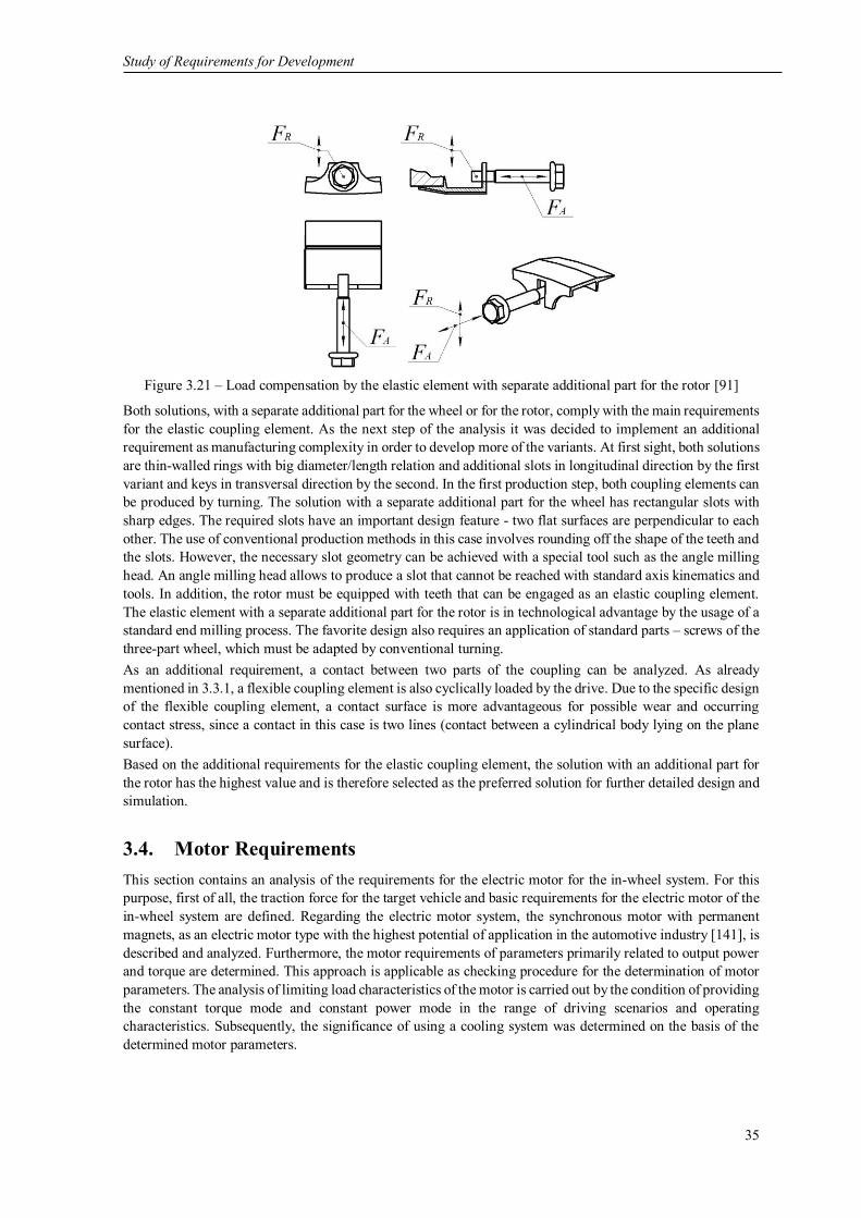
Study of Requirements for Development
35
Figure 3.21 – Load compensation by the elastic element with separate additional part for the rotor [91]
Both solutions, with a separate additional part for the wheel or for the rotor, comply with the main requirements
for the elastic coupling element. As the next step of the analysis it was decided to implement an additional
requirement as manufacturing complexity in order to develop more of the variants. At first sight, both solutions
are thin-walled rings with big diameter/length relation and additional slots in longitudinal direction by the first
variant and keys in transversal direction by the second. In the first production step, both coupling elements can
be produced by turning. The solution with a separate additional part for the wheel has rectangular slots with
sharp edges. The required slots have an important design feature - two flat surfaces are perpendicular to each
other. The use of conventional production methods in this case involves rounding off the shape of the teeth and
the slots. However, the necessary slot geometry can be achieved with a special tool such as the angle milling
head. An angle milling head allows to produce a slot that cannot be reached with standard axis kinematics and
tools. In addition, the rotor must be equipped with teeth that can be engaged as an elastic coupling element.
The elastic element with a separate additional part for the rotor is in technological advantage by the usage of a
standard end milling process. The favorite design also requires an application of standard parts – screws of the
three-part wheel, which must be adapted by conventional turning.
As an additional requirement, a contact between two parts of the coupling can be analyzed. As already
mentioned in 3.3.1, a flexible coupling element is also cyclically loaded by the drive. Due to the specific design
of the flexible coupling element, a contact surface is more advantageous for possible wear and occurring
contact stress, since a contact in this case is two lines (contact between a cylindrical body lying on the plane
surface).
Based on the additional requirements for the elastic coupling element, the solution with an additional part for
the rotor has the highest value and is therefore selected as the preferred solution for further detailed design and
simulation.
3.4. Motor Requirements
This section contains an analysis of the requirements for the electric motor for the in-wheel system. For this
purpose, first of all, the traction force for the target vehicle and basic requirements for the electric motor of the
in-wheel system are defined. Regarding the electric motor system, the synchronous motor with permanent
magnets, as an electric motor type with the highest potential of application in the automotive industry [141], is
described and analyzed. Furthermore, the motor requirements of parameters primarily related to output power
and torque are determined. This approach is applicable as checking procedure for the determination of motor
parameters. The analysis of limiting load characteristics of the motor is carried out by the condition of providing
the constant torque mode and constant power mode in the range of driving scenarios and operating
characteristics. Subsequently, the significance of using a cooling system was determined on the basis of the
determined motor parameters.

Study of Requirements for Development
36
3.4.1. Energy Demands of the Vehicle
The extension of the in-wheel system to passenger vehicles faces significant difficulties, as the use of the active
volume of the motor decreases with the reduction of the unit power of the electric motor. Conversely,
restrictions imposed on the unsprung mass of a passenger vehicle require a significant reduction in the size of
the motor, which in turn is accompanied by a decrease in its specific energy characteristics and is in
contradiction with the availability of a limited power supply on board of an electric vehicle. The requirement
for high energy performance is valid for all parts of the electric power transmission and, above all, for integrated
electric motors. The movement of an electric vehicle in an urban environment is characterized by frequent
stops and subsequent acceleration to a specified speed. Analytical study of this movement is usually carried
out by using the experimental speed graphs. The characteristics of the movement of an electric vehicle in a city
depend on its structural design and the functional purpose of the vehicle (transportation of mail, public services,
etc.) and have to be developed for each city separately with regard to its characteristics. The most responsible
mode of car traffic is acceleration from parking to maximum speed and gradeability on a slope. Therefore, to
determine a driving performance using in-wheel motors certain requirements have to be fixed:
- Maximum speed of 150 km/h (see 3.1),
- Driving a slope of 30%,
- Acceleration from stillstand to 100 km/h in at least 20 s,
- Grade on a street curb.
The general vehicle movement can be mathematically described with the general principles of mechanics.
Traction effort 𝐹𝑡 is transferred to wheels and is acting in the direction of movement of the vehicle. By the
movement of the vehicle also traction resistances 𝐹𝑡𝑟 occur as tire rolling resistance, aerodynamic drag and
grading resistance. When the 𝐹𝑡 value exceeds the 𝐹𝑡𝑟 value, the vehicle starts moving in the direction of 𝐹𝑡
and it can be expressed by the Newton’s Second Law of Motion as:
𝑑𝑉
𝑑𝑡=
∑ 𝐹𝑡 − ∑ 𝐹𝑡𝑟
𝑚𝑣
(3.4)
According to Equation (3.4), traction effort 𝐹𝑡 must be provided by the in-wheel motor system. In order to
derive the requirements for the in-wheel system, it is necessary to define various requirements for the integrated
electric motor.
For determination of the main requirements for the integrated motor, the forces acting on the driving vehicle
and having the greatest impact on these requirements must be identified. The forces of traction resistance
include aerodynamic drag 𝐹𝑎𝑑, rolling resistance 𝐹𝑟𝑑 and grading resistance 𝐹𝑔𝑟𝑎𝑑 as it is shown in Figure 3.22.
mvg
α
Figure 3.22 – Forces acting on a vehicle

Study of Requirements for Development
37
An aerodynamic drag 𝐹𝑎𝑑 is the resistance to the air flow and depends on the air density 𝜌𝑎𝑖𝑟, the aerodynamic
drag coefficient of the body of the vehicle 𝑐𝑤, the frontal area of the vehicle’s body 𝐴𝑓, and the speed of the
vehicle 𝑉 in accordance with the Equation (3.5):
𝐹𝑎𝑑 =1
2∙ 𝜌𝑎𝑖𝑟 ∙ 𝑐𝑤 ∙ 𝐴𝑓 ∙ 𝑉2 (3.5)
The rolling resistance 𝐹𝑟𝑑 of the vehicle wheels in contact with the road surface mostly depends on the rolling
resistance coefficient 𝑓𝑟𝑟, which furthermore depends on the rolling resistance as a function of the driving speed
and according to recommendations in literature [50] have a value of 0.017 at 150 km/h. Taking into account
the dynamic radius 𝑟𝑑𝑦𝑛 , an expression for the force of rolling resistance could be expressed as:
𝐹𝑟𝑑 =𝑓𝑟𝑟
𝑟𝑑𝑦𝑛
∙ 𝑚𝑣 ∙ 𝑔 (3.6)
To assess the traction effort 𝐹𝑡 and power required to drive at maximum speed, the road is considered to be
strictly horizontal. Then an expected resistance force 𝐹𝑡𝑟 at maximum speed requires a power 𝑃𝑚𝑒𝑐ℎ, that can
be calculated by multiplying by the maximum speed 𝑉𝑚𝑎𝑥 :
𝑃𝑚𝑒𝑐ℎ = 𝐹𝑡𝑟 ∙ 𝑉𝑚𝑎𝑥 (3.7)
𝑉𝑚𝑎𝑥 is determined above in section 3.1 in compliance with the requirement of the target vehicle. According
to Equation (3.7) and predefined and precalculated data, the required power to achieve the maximum speed of
the vehicle has to be 69.9 kW. For simplification of the future calculations, the required power of 70 kW was
accepted.
Maximum traction effort is also determined by the slope of the road, which needs to be crossed either in short-
time mode or permanently. Normally the maximum slope for passenger vehicles is to be found on multilevel
parking and mountain roads. For parking areas in Germany, the road angle α is brought up to 30% or 17° [50].
Accordingly, an analysis of grading resistance 𝐹𝑔𝑟𝑎𝑑 should take into account both, the force of rolling
resistance and the projection of the force of gravity:
𝐹𝑔𝑟𝑎𝑑 = 𝑚𝑣 ∙ 𝑔 ∙ (sin 𝛼 +𝑓𝑟𝑟
𝑟𝑑𝑦𝑛
∙ cos 𝛼) (3.8)
In order to be able to make an explicit statement about the suitability of the developed in-wheel motor, the
required drive torque 𝑀𝑚𝑒𝑐ℎ related to one wheel can be illustratively calculated based on the value of 𝐹𝑔𝑟𝑎𝑑 .
𝑀𝑚𝑒𝑐ℎ =1
2∙ 𝐹𝑔𝑟𝑎𝑑 ∙ 𝑟𝑑𝑦𝑛 (3.9)
At this point, a decision about the motorization of the vehicle axis can be made by the distribution of required
torque on one or two axes. Required drive torque value is 1080.5 Nm and can be provided from the one axis
of the vehicle. However, motor torque 𝑀𝑚𝑒𝑐ℎ for each in-wheel motor is expected by 540.25 Nm which is
suitable for traction as well as for braking.
For the further determination of parameters of the motor, the following assumption is made: vehicle climbing
grade with a maximal speed 𝑉𝑔𝑟𝑎𝑑 of 75 km/h, whose value is half of the value for 𝑉𝑚𝑎𝑥 . Accordingly, a power
demand for a situation, where a 30% slope is climbed by the vehicle, has a value of 71.1 kW per in-wheel
motor. Comparing the required power values for two critical applications of a motorized vehicle, it can be
concluded that the electric motor of the in-wheel motor must be calculated in accordance to satisfy the power
demand.
The power needed for acceleration from stillstand to 100 km/h in required time 𝑡𝑟𝑒𝑞 (20 s) is calculated as:
𝑃𝑚𝑒𝑐ℎ =𝑉𝑚𝑎𝑥
2 ∙ 𝑚𝑣
𝑡𝑟𝑒𝑞
(3.10)

Study of Requirements for Development
38
The height of curb that must be climbed by the vehicle has an important role during parking maneuvers. An
electric vehicle has to be able to overcome the same obstacles as vehicles with internal combustion engine
have. According to [14] the curbstone height in Germany ranges from 10 cm to 12 cm. The length of the lever
arm depends on the climbed curb height and radius of the tire and can be calculated as:
𝑙𝑎 = √2 ∙ ℎ𝑐 ∙ 𝑟𝑡 − ℎ𝑐2 (3.11)
The amount of driving torque 𝑀𝑚𝑒𝑐ℎ that the electric motor has to deliver to overcome the curbstone can be
calculated by:
𝑀𝑚𝑒𝑐ℎ = 𝑙𝑎 ∙𝑚𝑣
2∙ 𝑔 (3.12)
The results of calculated torque and power values as requirements of the in-wheel motor presents Table 3.3:
Requirements Torque 𝑀𝑚𝑒𝑐ℎ, Nm Power 𝑃𝑚𝑒𝑐ℎ, kW
Maximum speed by 150 km/h 265.7 70
Driving a slope of 30% 540.3 71.1
Acceleration from stillstand to 100 km/h in 20 s - 87.25
Grade on a street curb 1133.3 -
Table 3.3 – Torque and power needed for the fulfillment of requirements of the driving performance of the
in-wheel motor
Also, it should be paid attention to the operating mode of the developed in-wheel motor. As an example, Tesla
Motors’ vehicles can be introduced, which have a high-power density of 4.5 kW/kg [2]. However, this
parameter is given for short-term operation and tests show, that the Tesla Model S is losing its dynamics after
a short time due to motor protection from overheating. In addition, under normal conditions, the specified 515
kW power is not needed so often that the motor has time to warm up significantly, so that the normal driver
does not have to struggle with the power limitation mode during normal daytime operation. In this regard, the
overload conditions for the developed electrical motor are required to be determined as 70 kW power and 565
Nm torque value.
3.4.2. Parameters of the Motor
Common strengths of motors for electric vehicles are high efficiency, optimal controllability and a very small
environmental impact [90]. Further important aspects of electric machines for an immediate in-wheel
application are as follows:
- the maximum efficiency level for continuous operation,
- high efficiency ratio over the entire speed range,
- a limited value of unsprung masses,
- a torque overload ability in accordance with the power supply capacity (current, voltage and power
limitations) and significant torque reserve for improved driveability and gradeability,
- low noise level (including magnetic origin),
- absence of contacts, simplicity of maintenance.
Graphic representation of the load characteristics of an electric motor for achievable driving performance can
be displayed in a torque-speed diagram as in Figure 3.23. This diagram provides information that the motor is
able to be operated backwards and forwards, as well as that the motor can be driven and braked (see e.g. [40]
and [76]), which is a significant aspect for an application in an electric vehicle. The main focus of this diagram
is the area in which the vehicle moves forward, as this is the main function of the vehicle. The forward braking
area corresponds to the operation of the motor as generator to recuperate the kinetic energy of the vehicle.
Furthermore, there are two ranges that are distinguished: the constant torque range (basic speed range) and the
field weakening range. In the first range, the continuous torque (nominal torque) or the peak torque for a short
time (e.g. acceleration or climbing a curb) can be specified and is already available for starting. In case that
speed is increased at nominal torque, the mechanical power also increases until the nominal power is reached.

Study of Requirements for Development
39
That is why for the possibility of rotational speeds by nominal power the torque must be reduced with
increasing speed. By these conditions a range of constant power is realized. Therefore, the electric motor has
to be able to demand higher power to deliver the discussed range of specified motor performance scenarios.
Figure 3.23 – Torque-speed diagram for permanent magnet synchronous motor
From the diagram it is possible to calculate the current, voltage and electrical power limits of the motor. A
torque-speed diagram can be influenced by relatively simple parameter variations, for example by varying the
number of pole pairs, what allows to define any operating point of the motor in a relatively simple way. It is
also necessary to consider the fact, that an in-wheel motor is a system that is operated under conditions of
limited power supply. These are limitations e.g. of maximum current of supply cables, battery current and
voltage, etc. This circumstance inevitably develops an electric motor to ensure the operation of the motor in
two control ranges: left and right from of the nominal speed. It should be noted that the control downwards of
nominal speed can be provided by the torque constancy mode and control upwards can be provided by the
power constancy mode.
The fulfillment of in-wheel motor requirements leads to the implementation of new non-traditional motor
designs with increased active volume level. The last mentioned is possible due to the application of the
synchronous motor with permanent magnets or so-called PMSM by using a special combined winding.
The torque generating in a PMSM motor takes place in the magnetically active air gap between stator and rotor.
To generate a sufficiently high torque in the installation space limited by the wheel, the motor must have a
specific force density related to the air gap to be as high as possible. The actual torque generation is based on
the main effect of the force effect in the magnetic field. One part of the meandering copper winding is the air
gap winding and another part is the slot winding. The air gap winding is glued onto a thin foil directly onto the
stator back iron and the slot winding is inserted into the slots of the back iron. The cross-section view of the
winding phases is shown schematically in Figure 3.24. The meander-shaped structure and changing orientation
of the permanent magnets corresponds to the alternating current flows in the respective phases. Since all three
phases together are as wide as a permanent magnet, each magnetic pole can be used at the same time for torque
generation by using the Lorentz force. This results in an evenly variation of torque over the total circumference
of the in-wheel motor.

Study of Requirements for Development
40
Back iron
Laminated core
Stator
Rotor
Magnet Magnet
Air gap
winding
Slot
winding
Figure 3.24 – Schematic diagram of combined winding [17]
Interactions that are responsible for energy conversion can be explained on the basis of the physical appearance
of the Lorentz force. The Lorentz force is a force which acts on a current carrying conductor (combined
windings) in a magnetic field. The general Equation for the Lorentz force according to [20] is:
𝐹𝐿 = 𝑙𝑐𝑐 ∙ 𝐼 ∙ 𝐵𝐻 (3.13)
with the current 𝐼, the length 𝑙𝑐𝑐 interspersed by the magnetic field, the magnetic field 𝐵𝐻 . For a common
torque, it must be ensured that each individually formed force acts in the same direction. For this purpose, the
current flow directions must be the same. The generated motor torque for combined winding can be
approximately calculated as a torque that is proportional to the number of pole pairs, the magnetic flux of the
permanent magnets and the air gap radius, as Equation (3.14) describes:
𝑀𝑒𝑙 = 2 ∙ 𝑝𝑝 ∙ 𝑟𝑎𝑔 ∙ 𝐹𝐿 = 𝑝𝑝 ∙ 𝑟𝑎𝑔 ∙ 𝑙𝑐𝑐 ∙ 𝐼 ∙ 𝐵𝐻 (3.14)
Thus, the motor torque is at first depending on the variable string current, the final proportional relation
between torque and current is expressed by the motor constant 𝑘𝑀:
𝑀𝑒𝑙 = 𝑘𝑀 ∙ 𝐼 ∙ 𝐵𝐻 (3.15)
𝑘𝑀 can be expressed as:
𝑘𝑀 = 2 ∙ 𝑝𝑝 ∙ 𝑟𝑎𝑔 ∙ 𝑙𝑐𝑐 ∙ 𝐵𝐻 (3.16)
The same motor constant 𝑘𝑀 can be used for the proportional relationship between induced counter-voltage
𝑈𝑀 and angular frequency of the motor 𝜔𝑀:
𝑈𝑀 = 𝜔𝑀 ∙ 𝑘𝑀 (3.17)
An electric quantity flowing through the cross-section of a circuit is an amount of current in the circuit.
Consequently, the electrical power is directly proportional to the potential difference and the current in the
circuit (see Equation (3.18)):
𝑃𝑒𝑙 = 𝑈𝑀 ∙ 𝐼 (3.18)
Thus, from the calculation of the required torque of the electric motor for an in-wheel motor, it can be seen
that the motor constant 𝑘𝑀 and the value of the magnetic field 𝐵𝐻 have a leading influence. It is worth
mentioning that 𝑘𝑀 depends on the motor parameters, which are essentially geometric. And the influence on
the value of the magnetic field can be achieved only by two options: Either the selection of the magnetic
assembly or application of different materials. Furthermore, advanced parameters of the motor with air gap and
slot winding can be determined according to the approaches highlighted in [90][19] [20][91].

Study of Requirements for Development
41
3.4.3. Losses and Cooling of the Motor
High output of mechanical power in the in-wheel motor results in a big amount of generated heat. Losses are
occurring in the form of heat, that must be dissipated via cooling, which is explained in this section. Due to
this, a considerable attention must be paid on various loss effects for the electric motor. Losses occur during
the converting of electrical energy into mechanical energy. Generally, these losses are expressed by the
efficiency, which describes the relation between input power and output power. Efficiency provides
information about the supplied and removed power and the proportion of losses regarding a motor [26].
𝜂𝑚𝑜𝑡𝑜𝑟 =𝑃𝑚𝑒𝑐ℎ
𝑃𝑒𝑙
(3.19)
First, mechanical losses occur in the form of friction at the motor bearing and sealing or due to the air drag
resistance. Copper losses are the biggest source of inefficiency in motors. These losses describe losses of energy
as heat losses due to the electrical resistance of the wire used for winding [51]. The current 𝐼 by the copper
losses is quadratic and this means that with increasing load, the copper losses increase exponentially.
Additional losses in form of iron losses, including eddy current losses and hysteresis losses, losses in the core
are arising. Iron losses depend on motor speed and are minimized by the use of a core material with low
remanence and high electrical resistance, which is often achieved through special lamination. In addition,
because the magnetic field in the motor windings changes over time, these changings cause eddy currents in
electrically inactive parts [117]. The eddy current loss occurs in the form of heat and heat accumulates in the
iron parts of the motor. Further sources of losses in motor are insignificant and include magnetostriction,
electromagnetic radiation and dielectric losses in materials used for core isolation and windings.
According to the second law of thermodynamics, a process in which energy conversions occur, results in heat
dissipation. This heat must be dissipated from the process, with its system boundary, for example an electric
motor, otherwise the temperature of the system would continue to rise and components of the motor could fail.
Considering the cooling methods for the in-wheel motor, a comparison between the cooling methods and the
cooling medium can be made. Surface cooling, internal cooling and closed-circuit cooling are the three main
cooling methods [40]. The mentioned cooling methods are designable as direct or indirect cooling. In case of
indirect cooling, there is a spatial separation between the heat source and the heat sink, e.g. by heat-conducting
walls. In case of direct cooling, the cooling medium (heat sink) is in direct contact with the heat source.
Closed-circuit cooling is an indirect form of cooling in which the primary cooling medium is conveyed in a
closed circuit and the heat is supplied to a secondary cooling medium. This concept enables intensive cooling
of closed cooling structures using fluids (water, water glycol mixture, etc.) instead of air as a coolant. In the
literature, there are several applications of the closed-circuit cooling to electric vehicles using a water jacket in
the machine housing [124] [186].
From 3.4.1 it is known that the electric motor is able to provide twice as much of the nominal torque for a short
time, with an intensive heat emission being expected. A necessary requirement for the operation of the motor
is the ability to dissipate resulting heat loss for every required application. For these purposes, active circuit
cooling of the windings as the part of the motor, which is most exposed to heat, is required. Therefore, an active
liquid cooling for the windings limits the winding temperature 𝑇𝑤_𝑚𝑎𝑥 to 125°C according to the automotive
thermal requirements [8]. Furthermore, as the target in compliance with the automotive thermal requirements
according to [8], a Grade 1 with the temperature range from -40°C for winter conditions to 𝑇𝑤_𝑚𝑎𝑥 for the
maximum motor coil temperature was accepted, thus a high thermal stress on the in-wheel motor system is
expected.
The highest temperature differences occurring between the windings and the cooling channel essentially
depend on the thermal resistances [145]. From the technological and manufacturing point of view, thermal
resistances of windings are the electrical insulation of the wires, any production-related air gaps between parts
and the distance to the cooling channels and their internal resistance. An effective cooling has to be able to
keep the temperature difference between the copper winding and the cooling fluid as small as possible. In
addition, a low flow resistance in the cooling channels, a small temperature difference between the inflowing
and outflowing cooling medium and a maximum difference of 10°C is also required. From this perspective, a
sufficient thermal conductivity and a thin layer of insulation and adhesive bonds between the motor

Study of Requirements for Development
42
components are required. These requirements prevent possible mechanical stress by excessive temperature
differences. The findings of the cooling requirements can be considered in more detail within the development
process of the in-wheel motor.
3.5. Motor Weight Requirements
In addition to the requirements analyzed in the previous section for the driving performance, the driving
behavior is an important parameter in terms of human perception [24]. In this section, the requirement for the
lowest weight for the developed in-wheel motor system and possible solutions of this problem are presented.
3.5.1. Unsprung Weights Consideration
Unsprung weight or non-suspended weight is an important parameter, because it is a key part of the total
evaluation, engineering and development of a vehicle. Traditional development of chassis always has the goal
to keep the unsprung weights as low as possible in order to guarantee a high level of driving behavior, which
depends on the compromise between agility, driving safety and driving comfort. For example, human
perception of a vibration in vertical direction between 4 and 8 Hz and a vibration between 1 and 2 Hz in the
transversal direction are considered to be annoying and uncomfortable [58]. The vehicle's suspension, as a part
of the chassis, has the main function to isolate and to absorb vibrations caused by road disturbances [157].
Nishioka in [122] estimated, the larger the so-called unsprung mass is (i.e. the mass of unsprung parts such as
wheels, pivots and suspension levers), the worse the vehicle's road holding performance will be due to
variations of the road engaging the force of the tire when the vehicle is running on an unstable road. The
integration of an electric motor in the wheel serves additional requirements with regard to the vehicle dynamics,
because the weights of the motor and necessary components add up to the unsprung weights, therefore a more
precise analysis of these effects is necessary. Some preliminary work focused on the effect of unsprung weights
has been carried out by [5] and [6], however there are still some critical issues like high vibration frequency
up to 80 Hertz that can act on the embedded electronics [151]. There was a study done by Watts et al. [177]
and a very rigorous analysis conducted on a very difficult situation with a relatively small and lightweight
vehicle (Ford Focus). By the evaluation of both variants (without and with additional unsprung weights on the
wheel) in terms of objective, numerical as well as subjective measures were found, so that there is a difference
in how the vehicle behaves, but that difference could be recovered with traditional riding and handling
techniques. Several further studies addressing to unsprung weights, for example [121] and [176], have been
carried out. They conclude, that increase in unsprung weights causes negative influence on vertical and pitch
acceleration of the vehicle, that can lead to degradation of the vehicle driving behavior. Otherwise, integration
of the in-wheel motor is possible by the rebalancing the vehicle parameters to achieve the best driving
performance. In [167] the authors also show that the added wheel mass has no effect on the stability of the
vehicle and that the frequency response is within the accepted comfort range. More recent evidence proposes
that the suspension system of a standard vehicle can be used for an in-wheel application without loss of comfort
or safety [172].
To overcome the disadvantage of unsprung weights an active suspension system has been developed, e.g.
Bridgestone has designed the Advanced Dynamic Damper Motor – a technology to control the unsprung weight
of the vehicle [114]. It involves the usage of the vibration absorption system, where the motors provide the
function of vibration dampers. This means that the vibration of the electric motors is compensated by their own
vibration from the road and tires, which improves the stability and comfort of driving. The Bridgestone proves
to be a success of this approach, as unsprung weight management provides reliability and durability of the in-
wheel motor. A further example of a solution to the problem of unsprung weight is Michelin's experience with
Active Wheel technology [110]. By Active Wheel an integrated in-wheel motor control system compares and
optimizes the weight balance of the wheels. With a significant mass of unsprung vehicle components such as
an in-wheel motor (up to 40 kg), the importance of this control system increases.
The arguments provided above prove that chassis components can and must be adapted to the higher unsprung
weights in order to reduce the negative effects of unspung weights. Nevertheless, based on the assumption that
the effect of the increased unsprung weight on the driving behavior is acceptable, minimizing unsprung weights

Study of Requirements for Development
43
by minimizing the total weight of the in-wheel motor has an attractive potential for additional improvements.
An approach of the weight limitation through the lightweight design of the in-wheel motor has been taken into
account in this work to minimize the influence of unsprung weights on dynamic loads and to optimize the
vehicle’s performance.
Lightweight design criteria have to meet two areas conflicting with each other. At first sight, the total weight
of the motor must be kept as low as possible to reduce the impact of non-suspended weight on the vehicle
performance. And, at the same time the low weight decreases the stiffness of the motor parts, which can affect
a value of the air gap and, accordingly, the main function of the electric motor.
3.5.2. Material Analysis
The easiest method for a lightweight construction is to use materials with a low density. Currently in literature,
only a few application examples of lightweight technologies for in-wheel motors can be found. Recently within
the MEHREN research project, the Schaeffler AG is working on the next generation of in-wheel motors, shown
in Figure 3.25, (a), together with Ford and Continental as well as the RWTH Aachen University and the
University of Applied Sciences in Regensburg. However, the main objective of this project is rather to find an
area for a multi-engine electric vehicle with highly efficient use of space and energy and uncompromising
driving safety [178].
There are other projects where the lightweight construction of the chassis is the main research trend. Another
example is the research project FAIR in which BMW Group, Schaeffler AG and DLR develop a concept with
an axle e-drive and a 2-step gear box [138].
The LEICHT project is also more oriented towards a significant weight reduction by integrating the motor in
an intelligent way through the development of innovative lightweight chassis systems, taking into account the
electrical drives [75].
Via the application of a carbon fiber reinforced polymer wheel with an integrated electric motor, shown
in Figure 3.25, (b), and demonstrated by Fraunhofer LBF in the field of electromobility, the reduction of weight
and noise emissions is being researched, with the application of high modulus fibers in fiber reinforced plastics,
compared to the use of metal instead [55].
a b
Figure 3.25 – a - In-wheel motor from Schaeffler AG [178], b - Demonstrator of Fraunhofer LBF [153]
The overview of above introduced concepts shows that there are many possibilities of lightweight solutions for
e-mobility, based on the application in in-wheel motors. But there is a lack of information about the precise
use of sandwich structures of carbon fiber reinforced plastics and aluminum foams. Therefore, it seems to be
necessary to introduce what potentials carbon fiber reinforced plastics and aluminum foam applications have
for the lightweight concepts of in-wheel motors.
Material analysis is one of the important stages in motor design. Each material has its own unique properties,
which determine the degree to which its tasks are fulfilled. From another point of view, material selection is
aiming for the identification of future manufacturing processes [47].
For applications ranging from satellites, aircraft, ships, automotive, rail cars, wind energy systems and
bridge construction, the use of sandwich structures increases rapidly. Sandwich constructions have many

Study of Requirements for Development
44
advantages for the development of parts that have always been solid and can therefore be given a new design
in lightweight structures. Sandwich solutions are being extensively and increasingly used in lightweight
constructions because they are light in weight, energy efficient, aesthetically attractive and can easily be
handled and built [168].
The sandwich structure, as it is shown in Figure 3.26, has always the same basic idea: two facings (skins) which
are relatively thin and have high-strength characteristics, enclose a relatively thick and lightweight core with
specified stiffness in a direction that is normal to the faces of the structure [136].
Figure 3.26 – Structure of a typical sandwich [136]
There are many alternative forms of sandwiches known by combining different facings and core materials. The
facings can be steel, aluminum, wood, fiber reinforced plastics etc. The core part can, for example, be made of
cork, rubber, plastics or synthetic or metal foam materials [35]. The possibility of combining materials to form
sandwiches enables optimum designs to produce particular applications. In such a way, the positive properties
of individual materials can be combined and the negative properties can be eliminated in sandwich structures
[7].
Carbon and glass fiber reinforced plastics: The use of fiber reinforced composites in vehicles has grown
significantly, but mostly through the application of glass fiber reinforced plastics in areas of vehicle body parts
[113]. These composites have a high specific stiffness and strength and excel conventional steel and cast
materials in terms of fatigue strength and thermal expansion. Fiber reinforced composites are created by
combination of fibers in a matrix. Carbon fibers possess much higher strength than fibers of glass. This is why
they rather fit into applications that require a high stiffness.
Carbon fiber reinforced plastics have densities of about 1.3 to 1.8 g/cm3, glass fiber reinforced plastics are in a
range of about 1.8 to 2.2 g/cm3. However, a high level of engineering costs must be taken into account by
replacing conventional materials through fiber reinforced plastic composites. But for prototypes, the in-wheel
motor can be used to show what kind of potential exists in terms of weight savings [136].
Metal foams: Metal foams are a new class of materials with low densities and novel physical, mechanic,
thermal, electric and acoustic properties [7].
The biggest advantage of metal foams is a low density in combination with a high stiffness. The cellular
structure also allows a very good energy absorption and damping capacity. The first series of applications in
mechanical engineering as a lightweight construction and damping element and in automotive engineering as
crash absorbers have proved this statement to be true.
In the production of metal foams, a large number of variants of forms and parts could be realized. The variety
of products based on metal foam sandwich technology shows Figure 3.27. A goal is to obtain varieties that
have suitable forms and shapes for further implementations in lightweight designs for in-wheel motor parts.
Figure 3.27 – Variety of products based on metal foam sandwich technology [136]

Study of Requirements for Development
45
3.6. Preliminary Results
In the presented chapter, the requirements for the in-wheel motors are determined. Firstly, to limit the possible
area of application, assumptions and requirements according to the target vehicle based on the most widespread
segments of the passenger vehicle stock in Germany were made. Furthermore, the topology based on the
functional basics of the in-wheel motor was described and structural synthesis of the motor topology was
performed. A wheel hub bearing was selected as a rigid element in the force flow. A wheel hub bearing is
required to satisfy two conflicting properties: minimal weight and maximal stiffness. From this point of view,
a wheel hub bearing of the 3rd generation was selected. According to the established topology, requirements on
the elastic coupling element were developed. For this reason, loads acting on the wheel were classified and the
most critical load scenarios were considered and subsequently, the generation of the critical loads for the in-
wheel motor was carried out. As a possible solution in the area of torque transfer, the standard couplings were
observed and a need of special coupling structure was detected. The presented two variants of elastic coupling
are able to meet not only the requirement for torque transfer with different contact areas but also with different
manufacturing demands. In addition, a technologically less difficult variant was preferred in order to avoid
potential challenges in production during further development. The performance of the electric motor was
investigated by the requirement on the energy demands of the target vehicle. For this reason, a general
description of the vehicle movement was mathematically transcribed to determine the typical resistance and
energy demands of the driving performance. Therefore, certain operating conditions like the maximum speed
of 150 km/h, driving a slope of 30%, acceleration from stillstand to 100 km/h in at least 20 s and grade on a
street curb were fixed. Depending on the operating condition, there were parameters primarily related to each
other and output power as well as torque for these conditions were specified. The analysis of limiting load
characteristics of the motor was carried out based on the condition of providing the maximum torque and
maximum power in the range of operating scenarios. Hereupon, according to the determined motor parameters
and thereby resulting losses, the importance of using an active cooling system was derived. The foregoing
discussion was attempted on the most contradictory condition of the in-wheel motor – the demand for the low
weight, caused by the requirement on the high driving performance by the high driving behavior. The main
aspect here is that an unsprung weight attributable to the in-wheel motor was considered as a reason that this
effect would not be prohibitive according to the known developments and research. However, to keep unsprung
weight low is certainly a design requirement. The most common method for lightweight construction were
analyzed materials with a low density and lightweight technologies according to their application on the in-
wheel motor. Modern lightweight technologies – aluminium foams and carbon fiber reinforced polymers in
designs for in-wheel motors were decided to reduce the weight of the motor.
A brief description of technical requirements for the in-wheel motor according to the analysis as well as
summary data of parameters and characteristics are presented in Table 3.4.

Study of Requirements for Development
46
Requirement Symbol Unit Value
Requirements on the vehicle
Vehicle weight 𝑚𝑣 kg 2010
Wheel size 𝑊𝑣 inch 16
Structural design of the wheel multi-part wheel
Working space mm Ø356 x 156
Dynamic radius 𝑟𝑑𝑦𝑛 mm 316.8
Maximum speed 𝑉𝑚𝑎𝑥 km/h 150
Drag coefficient 𝑐𝑤 0.27
Frontal area 𝐴𝑓 m2 2.2
Drive layout with load distribution rear-wheel, 50%
Requirements on the topology
Brake system not included
Wheel hub bearing BAR-0230, modified
Angular stiffness of wheel hub bearing 𝐶𝑡 Nm/° 5500
Requirements on the elastic coupling
Radial load 𝐹𝑅 kN 10.4
Axial load 𝐹𝐴 kN 10
Torque load 𝑀𝐿 Nm 2000
Loads compensation Technological easy elastic element, part of the rotor
Requirements on the motor
Electric motor type PMSM, outrunner
Maximum angular velocity 𝑛𝑚𝑎𝑥 min-1 1258.2
Nominal power 𝑃𝑛 kW 70
Maximum power 𝑃𝑚𝑎𝑥 kW 87.25
Nominal torque 𝑀𝑛 Nm 565
Maximum torque 𝑀𝑚𝑎𝑥 Nm 1133.3
Temperature range 𝑇𝑤_𝑚𝑖𝑛 … 𝑇𝑤_𝑚𝑎𝑥 °C -40 … +125
Requirements on the weight
Target weight 𝑚𝑚 kg Less 20
Desired materials Standard materials, CFPR, Al-foams
Table 3.4 – General parameters for development of the in-wheel motor

Development of Concept-dependent Components
47
4. Development of Concept-dependent Components
The previous chapter clarified that requirements for the development of the in-wheel motor are highly variable.
Interrelation and interdependence of requirements have a significant influence on the performance of the
electrical motor. In order to comply with the requirements that are critical for the motor, the model of the motor
and its parts serve as a development instrument to make the structure of the motor study more comprehensible
and to identify important cause-effect relations. The development strategy is segmented between main parts of
the in-wheel motor: the electrical and mechanical parts and the cooling system. To simplify the development
of the motor, its parts were divided into different subsystems. The developed subsystems have to comply with
the theoretically optimal model, but at the same time manufacturing errors, a variation of the characteristics
and a further simplification are allowed. Certain boundary conditions can be drawn from empirical engineering
knowledge. The subsystems of the motor and the applications of individual materials are to be understood as
typical and they may vary in certain applications due to different boundary conditions.
4.1. Electrical Part
The development of the electrical motor first begins with the rotor configuration, because the rotor has a
geometrical limitation of the wheel. The stator with its components and other motor relevant parts are described
below.
4.1.1. Rotor
Since the first bounding constraint is already accepted as the maximum diameter of the working space for the
developed motor, the second restriction represents materials that can be applied for the parts of the rotor before
final design and implementation could be started. Further rotor calculation depends directly on these two
boundary conditions. As an additional restriction, a minimum distance between the rotor outer housing and the
outer diameter of the considered working space of 3 mm is assumed.
4.1.1.1. Materials and Designs
For the development phase, firstly, standard materials are taken for all parts to define the main concept of the
in-wheel motor and to have a reference for the next analysis.
Figure 4.1 demonstrates the biggest parts of the motor, which are the covers and the housing of the rotor. These
parts are very suitable with more potential in the area of weight reduction. They present a thin-walled structure
that ideally fits for an implementation of lightweight concepts like aluminum foams or carbon fiber reinforced
plastics.
Figure 4.1 – Selected parts of the motor for implementation of lightweight concepts

Development of Concept-dependent Components
48
In a first step, a new design of rotor housing and cover parts made of aluminum foams was developed according
to the requirement profile. The concept presented in Figure 4.2, (a) includes two metal foam parts – right and
left covers. For both covers SAS-structures were selected which consist of 3 layers: 0.5 mm thick facings in
this case and 5 mm aluminum foam builds the core. The stability of the rotor housing made only from CFRP
is not especially high and can cause vibrational loads. The use of the sandwich for the rotor housing consisting
of aluminum foam core and CFRP facings increases the stability of the parts. Both designs also include parts
for the bearing from one side and the threaded connection from another side (see Figure 4.2, (b)).
a b
Figure 4.2 – Concepts of rotor: a - Rotor housing of aluminum foam (sandwich), b - Development of a hybrid
of aluminum foams and CFRP
Table 4.1 presents a comparison of the approximate weights of designs for the motor parts using lightweight
technologies. Compared to standard materials, aluminum foams and CFPRs are lighter and have a potential for
weight reduction, but technologically they are not characterized as the easiest way during the manufacturing
process. This points out the fact that standard materials represent a more realistic approach for the
manufacturing of the first prototypes of the developed in-wheel motor and the usage of the presented
lightweight technologies, as it is explained in the following sections.
Component /
Variant of version
Standard
materials CFPR
Aluminum
foams
Combination,
CFPR + Aluminum foam
Weight, kg
Rotor assembly 10.3 8.84 8.07 8.45
Table 4.1 – Calculated weights of rotor assembly
Details regarding the considered material for rotor back iron is presented in the literature (see e.g. [16] [17]
[21]). The rotor back iron is made of a ferromagnetic material with nonlinear permeability, which provides a
1.97 T magnetic flux density and saturation at 50 kA/m. Variants of rotor back iron and its relevance are more
detailly described in the following section.
As it was presented in 3.2.1 and 3.4.2, permanent magnets have a direct influence on the motor development
and future driving performance. The best magnetic material in terms of remanence flux density and coercivity
is NdFeB [34]. That is why sintered NdFeB magnets currently appear to be the most promising solution. The
main advantage of these magnets is the obtained value of the energy product (𝐵𝐻)𝑚𝑎𝑥, which is the largest of
all known materials with up to 5 T by ambient temperature and higher [28]. Secondly, NdFeB magnets are
characterized by a high Curie temperature of about 160-170°C for types with an operating temperature of 80
ºC [43]. The remanence flux density depends on the magnet temperature and as the magnet heats up, it is
reflected in an increase in current to produce an output torque [179]. For this reason, the main requirement for
the operation of the motor is to create operating conditions under which the magnets never enter the irreversible
demagnetization zone to avoid their demagnetization. However, NdFeB magnets are produced to cope with
operating temperatures up to 200°C nowadays, which opens up a broad perspective for their application. One
of the most important and essentially determining advantages of NdFeB magnets in terms of economics is their

Development of Concept-dependent Components
49
relatively low price in comparison with other types of known magnetic materials. NdFeB also has better
mechanical properties compared to e.g. SmCo-magnets, which is important for the production process [4]. As
mentioned by Hackmann [61], other magnets like ferrites or AlNiCo-magnets provide a low energy product
(𝐵𝐻)𝑚𝑎𝑥 and these magnets would require too much material to achieve the desired energy density in the air
gap. In order to make a choice with regards to the requirement on maximum temperature (see 3.4.3) for
prototyping purposes, the generic material N45SH as a material for permanent magnets was used. NdFeB
materials are sensitive to corrosion and react with oxygen in an untreated state resulting in very fast oxidation.
Therefore, NdFeB magnets need a corresponding surface protection. This is realized by using Ni-Cu-Ni
coating. The parameter values of accepted material are presented in Appendix C.
4.1.1.2. Number of Magnets and Magnetization Type
The number of magnets 𝑛𝑀 has a significant influence on the motor performance. According to Equation (3.14),
the pole pairs number or doubled number of magnets is proportional to the torque 𝑀𝑒𝑙 and can be recognized
as a pure geometrical coefficient. On the one hand, a maximization of the number of magnets leads to increasing
motor torque, but on the other hand there is a complex of restrictions caused by the geometrical limitations of
the inner diameter and the length of the rotor part and manufacturing limits of the magnet width 𝑤𝑀 .
Considering the given rotor outer diameter in accordance with physically limited working space of the wheel,
the first restriction on the rotor inner diameter 𝐷𝑖𝑟 has its maximum at 350 mm. Therefore, the distance of 3
mm is provided as a gap between wheel rim and rotor housing.
In case of a high number of magnets (𝑛𝑀>100), the difference between the width of the magnet and the arc
length required for its mounting consists of less than 0.001 mm. Assuming that the length of the arc is not
relevant for the calculation of the number of magnets, this difference can therefore be neglected for further
calculations.
The distance between the two magnets must consider the tolerances in magnet manufacturing. The tolerance
range used for the manufacture of 10 mm wide magnets is ±0.1 mm. By reducing the tolerance range, the
manufacturing of magnets becomes considerably more expensive [164]. According to the relevant tolerance
range and to the dimension chain, the minimum distance 𝑑𝑀 between the magnets requires at least a value of
0.2 mm. Under these circumstances, this parameter may have a higher value and may be adapted for the
required even number of magnets. The potential number of magnets can be calculated as:
𝑛𝑀 =π ∙ 𝐷𝑖𝑟
𝑑𝑀 + 𝑤𝑀
(4.1)
In this work, two magnetization types – a conventional radial magnetization and a Halbach array magnetization
– are presented with the target to minimize the weight of the rotor part of the developed motor, while the
magnetic flux density in the air gap between stator and rotor is maximized and maintained.
Conventional radial magnetization requires a back iron of the rotor. Therefore, the magnets are mounted on the
back iron with alternating polarity as shown in Figure 4.3, (a). The function of the back iron is to provide the
containing and conducting of the magnetic fields. To describe the behavior of the magnetic flux density in the
air gap by the variation of magnets, the parametric model was built upon a numerical finite elements’ method
analysis (see [21] for a model description). According to this model, a height of 5 mm for the back iron allows
the magnetic flux density to reach up to 1.10 T in the air gap.
As the next step of development, the inner diameter 𝐷𝑖𝑟 for the mounting of magnets has to be reduced by the
height of the back iron and has a value of 340 mm. The rotor back iron as a fully cylindrical part is presented
in Figure 4.4, (a). According to Equation (4.1), the developed motor by conventional radial magnetization can
be implemented with the number of magnets 𝑛𝑀 = 104.

Development of Concept-dependent Components
50
a b
Figure 4.3 – a - Magnetic circuit design for conventional radial magnetization [21], b - Shaping of the back
iron of the rotor
A possible solution to minimize the weight of the back iron of the rotor is shaping, as it is showed in Figure
4.3, (b) and Figure 4.4, (b). From this point of view, it is possible to make radial grooves with 𝑅𝑟𝑎𝑑 of 4 mm
into the rotor iron. The grooves must be positioned exactly radial to the magnet centers. A comparison of the
weight calculation of the back iron in CAD shows that the mentioned solution allows to reduce a rotor back
iron weight of about 2 kg, so the shaping can reduce the weight by 40%.
a b
Figure 4.4 – Variants of the rotor back iron: a - As fully cylindrical part, b - With radial shaping
Halbach array magnetization, first presented by Halbach has an arrangement of permanent magnets resulting
in a non-symmetric magnetic field [62]. Halbach magnetization consists of alternating axial and radial magnets
as it is shown in Figure 4.5. The key advantages of the Halbach array are that the field on the one side is
approximately doubled by the confined flux and the opposite side has a minimal stray field, which helps with
confinement and consequently reduces the chance of a flux leakage. These advantages have a significant impact
on the motor design, because the use of magnetic materials other than permanent magnets is not necessary.
Thus, there is no need to use back iron for retaining and the conducting of magnetic fields.
Further presented analyses are based on the assumption that for convenience of calculation and an aliquot
number of magnets the inner diameter 𝐷𝑖𝑟 is 342.6 mm. Based on this limitation, the outer diameter of the rotor
part as a support housing for magnets is considered to be 350.4 mm, which allows a 2.8 mm gap to the wheel
rim and a thickness of the rotor housing of ℎ𝐻 = 3.9 mm. As it can be derived from Figure 4.5, the Halbach
array is represented by a double number of physical magnets. To receive the magnetic field of a magnet, two
halves of axially magnetized magnets and a fully radially magnetized magnet are required. Thus, the magnets
with axial and radial magnetization become the half of the width compared to conventional radial
magnetization. According to this, also a smaller tolerance range of ±0.05 mm can be used. According to
Equation (4.1), the number of magnets 𝑛𝑀 for Halbach array can be calculated by 112 pieces. In terms of the
tolerance range, the width of one magnet with radial or axial magnetization 𝑛𝑀𝑝ℎ is 4.7±0.05 mm. It is
important to highlight that the weight of the rotor housing for magnets is only 1.38 kg if it is made of
conventional aluminum alloy.

Development of Concept-dependent Components
51
Figure 4.5 – Halbach array magnetization
Under the considered conditions, remarkable differences by the magnetization require additional weight and
volume by conventional radial magnetization. Research by Borchardt et al. [16] suggests that the comparison
of the weight of magnetization arrangements by conventional radial magnetization and Halbach array provides
an option of a weight reduction of about 51% of the rotor unit weight.
A simple comparison can be organized using Maxwell to observe the difference in magnetic fields by using
dipole and Halbach array arrangement. The following simulation shows two identical configurations according
to material and geometry, whereby the plate of the back iron in dipole variant is made of steel (Figure 4.6, (a))
and for Halbach array made of aluminum as depicted in Figure 4.6, (b).
a b
Figure 4.6 – FEM-simulation of magnetic flux distribution for: a - Standard dipole, b - Halbach array
a b
Figure 4.7 – Results of simulation of magnetic flux density for: a - Standard dipole, b - Halbach array
The simulation results shown in Figure 4.7 provide that Halbach arrays have clear advantages over a standard
dipole magnet configuration. The back iron of the rotor proves to be more effective in reducing leakage,
although its influence on improving the magnetic field density in the air gap is not as significant. Based on the
results of the simulation, a Halbach array is offered for further use in the developed motor, which can
effectively reduce the weight.

Development of Concept-dependent Components
52
4.1.1.3. Necessary Magnet Weight
In order to meet the required performance and lightweight requirements, great attention must be paid to the
required volume and the respective weight of the magnets 𝑚𝑀 during further development. This can be realized
using the magnet’s geometric parameter – height ℎ𝑀 and the length 𝑙𝑀.
A geometric parameter related to the driving performance of the developed motor is the length of the permanent
magnets. According to Equation (3.14), the length of the magnets has a proportional impact on the motor
torque. Based on the requirements for the working space of the motor and taking into account the additional
geometric spaces in the axial direction for the position of the windings, the length of the permanent magnets
𝑙𝑀 has been assumed to be 100 mm. In case of insufficient torque of the motor, this parameter can be used for
a detailed calculation of the motor parameters.
For the variant with a height value of the magnet ℎ𝑀 of 5 mm, a translational model of the magnetic circuits
for the Halbach array arrangement with similar geometry boundaries was presented by Borchardt in [21] in
order to simulate the magnetic flux density in the air gap. The translational model in this case is preferable,
while the differences to the rotational model are irrelevant. According to this approach, the mean magnetic flux
density 𝐵𝐻𝑚 for Halbach configuration with 1.5 mm air gap ℎ𝑎𝑔 is to be expected at 1.1 T.
To analyze the influence of different heights of the magnets ℎ𝑀 on the magnetic flux density, six different
heights were studied over the range of 2.5 mm to 5.0 mm (2.5, 3.0, 3.5, 4.0, 4.5, 5.0). In order to limit the
leakage flux and to minimize reluctance in the magnetic flux path, the value of the air gap was fixed at 1.5 mm.
Figure 4.8 shows the results of the FEM-simulation of the magnetic flux density for different heights of the
magnets ℎ𝑀. The software program used to analyze the data was Ansys Maxwell.
ℎ𝑀 = 5,0 𝑚𝑚
ℎ𝑀 = 4,5 𝑚𝑚
ℎ𝑀 = 4,0 𝑚𝑚
ℎ𝑀 = 3,5 𝑚𝑚
ℎ𝑀 = 3,0 𝑚𝑚
ℎ𝑀 = 2,5 𝑚𝑚
Figure 4.8 – Results of the simulation of the magnetic flux densities for different heights of magnets
The analysis identifies a significant difference between approachable magnetic flux densities for different
magnet heights. The higher the value of ℎ𝑀, the higher the magnetic flux density in the air gap. For the
development process, the height of the magnet ℎ𝑀 of 3.5 mm was considered as the value that meets the
production and machining limitations due to the high brittleness of thinner magnets and also due to the handling
that causes swarf/sludge formation [129]. From this point of view, the total weight of the magnets 𝑚𝑀 can be
reduced by 31.5% to 1.35 kg in comparison to the height of 5 mm.
In addition, as shown in Figure 4.6, (a), no ferromagnetic impurities adhere to the outer surface of the rotor in
the Halbach array, since the low magnetic flux is almost non-existent on the weak side - considering the
thickness of the rotor housing.
All results were obtained without the winding in the air gap, because the windings in deenergized condition do
not have a significant effect on the magnetic flux density [95]. Simulated results can then be used to determine
the geometry of the windings in the air gap.
4.1.2. Stator
The key aspect in this section is the definition of the characteristics of the stator as one of the main electric
components of an in-wheel motor. Therefore, the suitable materials for the main stator body are used as the
basis for the analysis of the estimated weight for the stator unit. Furthermore, approaches are presented and

Development of Concept-dependent Components
53
used to determine the winding and inlay characteristics for providing the necessary motor performance. The
implementation of the improved winding and inlay concept is evaluated on the basis of the theoretical, technical
and technological realization requirements and is integrated into the concept of the motor.
4.1.2.1. Materials
The materials of the stator as a second active part of the motor include not only the selection of materials for
the main parts – stator body, back iron and windings – but also for supplementary components such as
insulations, thermal couplings and magnetically conductive elements.
The design concept shown in Figure 4.9, (a) of the stator base body is developed in order to achieve the desired
aims of a lightweight construction. The densities of the individual materials indicate which material proportions
must be reduced in order to reduce the total weight of the stator. The first concept design consisted of an
aluminum base body with a magnesium cover and sleeve to close the one-sided cooling channels in the base
and surface area of the stator. The weight of this variant adds up to 3.83 kg, which compared to the full
aluminum variant resulted in a weight reduction of only 6.6%. In order to reduce the weight, it was essential
to significantly increase the content of magnesium in the stator body. Following this principle, the design
concept of a further variant is developed as it is shown in Figure 4.9, (b). The developed variant is characterized
by the circumstance that the stator base body also became an Al-Mg hybrid component. In the specific
implementation, the higher-loaded stator base body ground remained as an aluminum component, while the
cooling ring of the stator base body is replaced by magnesium. The one-sided cooling channels should be
closed with an aluminum cover. A magnesium sleeve is still used to close the cooling channels on one side in
the cover area of the stator base body. The Al-Mg variant has a weight of 3.45 kg and thus fulfilled the
lightweight requirements. Compared to the full aluminum variant, the weight saving amounts to 15.9%.
Nevertheless, due to the fundamental redesign of the Al-Mg lightweight stator, it is necessary to develop an
assembly technology suitable for production for connecting the stator base body bottom segment made of
aluminum with the stator base cooling segment made of magnesium. This resulted in the demand for a new Al-
Mg composite technology through production.
a b
Figure 4.9 – Stator body concepts: a - Full aluminum, b - Hybrid Al-Mg
To determine the materials used for the stator windings, it should first be clarified which structure a winding
concept has. Figure 4.10 shows a cross-section of the adhesive structure of the air gap winding.
Figure 4.10 – Structure of the air gap winding [163]

Development of Concept-dependent Components
54
In accordance to the manufacturing process of the stator motor active parts, the first layer presents a stator back
iron. The stator back iron consists of electrical sheets, which allow to reduce eddy current losses induced by
the fast-moving alternating magnetic field through the stator, whereby the very simple geometry of the flux-
carrying parts of the back iron enables simple and cost-effective sheet metal design. The electrical sheet is one
of the most important materials in electrical engineering [77]. Depending on the application, the electrical sheet
has to meet various requirements, whereby the most important are the magnetic properties: a high permeability
and a low loss, which have a particular significance for the realization of magnetic circuits. As it was figured
out above, the losses generated in the stator back iron are divided into hysteresis and eddy current losses. A
calculation method for determining the individual losses is given for example in [72] and [175]. Based on the
results presented by Zhitkova et al. in [186], it can be concluded that the NO20 electrical steel is most suitable
for the back iron development of the stator, as it is a typical economic material for high-performance electrical
traction drives. The biggest advantage by using NO20 is that the eddy currents in the back iron can be neglected.
A small sheet thickness of 0.2 mm has a significant impact on the motor performance, and an increase in
efficiency and thermal load on the motor can be expected within the permissible limits. An application of the
NO20 reduces iron losses to a minimum at high magnetization frequencies. Another advantage of using NO20
electrical steel is that it has a high permanence as well as a high flux density and therefore, a higher torque
density is to be anticipated. More details on the NO20 electrical steel are given in the Appendix D.
The insulation of the stator is located between the stator back iron and the copper wires of windings with the
function to protect the winding from damage. In order to achieve a high utilization of available space in the air
gap and a high thermal conductivity (dissipation of the generated heat), the insulation should have a layer
thickness which is as small as possible [72]. Research by Stamann et al. [163] pointed out that in addition to
the mechanical properties of the adhesive bond, thermal resistance, electrical insulation and dielectric strength
must also be taken into account when selecting an adhesive type to be used for fixing the air gap winding. It
has been suggested in [162] that the optimal adhesive result is obtained by fixing the copper wire of the air gap
winding with double-sided electrical adhesive foils on the stator. Double-sided adhesive foils are capable of
providing the main function of the stator insulation to retain the winding on the surface of the stator back iron.
Constant coating thickness of the foil by this technique plays a major role with regard to the very high demands
on the manufacturing tolerances for the parts in the air gap. Furthermore, the process cleanliness as well as the
so-called immediate adhesion are additional advantages of this adhesive technique. Based on these
requirements and according to the analysis presented in [163], the foil 70984 was selected to fix and insulate
the air gap winding. The detailed data sheet with more parameters of this foil can be found in Appendix E.
The next layer presents a copper wire as a part of the stator air gap winding. The stator winding is the main
component of the electric motor because it conducts the current and thus the torque of the electric motor is
generated. The most well-known parameter of the winding presents a fill factor, which can be explained as a
proportion between the effective and the theoretically maximum cross-sectional area of the copper conductors.
Apart from this statement, the insulation of the wire must be as thin as possible to provide the highest value of
the copper content in the windings. As a result, a low phase resistance is to be expected, which leads to the low
copper losses and enables a high motor efficiency. Additionally, as it is shown in Figure 4.10, a high power
density due to the high fill factor is provided by the rectangular cross-section of the wire. The developed motor
uses polyamide-imide enameled rectangular copper wire with the class N of insulation, which is capable of
operating up to a temperature of 220℃ [83]. The exact size and number of the used wires will be subsequently
chosen in 4.1.2.2. An example of copper wire and insulation for air gap winding with its tolerances is presented
in Appendix F.
The last layer of the air gap winding presents a bandage. The bandage is used in order to prevent the influence
and possible contact with the rotating parts on the windings, which have to be fixed in radial direction. The
winding packages are usually mechanically fixed by bandage tapes or rings. The most important mechanical
properties in this case are the tensile strength and the adhesive strength of the bandaging material. For the
developed motor, the 3M® insulating tape made of glass fiber fabric was used. This tape is a 0.17 mm thick
woven insulating glass fiber fabric tape with thermoplastic, and pressure sensitive adhesive is used for electrical
insulation and mechanical protection at temperatures up to 230°C. More properties of the selected bandaging
tape are given in Appendix G.

Development of Concept-dependent Components
55
The combined winding of the motor has a second winding – the slot winding. The slot winding, as it is presented
in Figure 4.11, is composed of the enameled rectangular copper wire similar to the wire of the air gap winding.
As it can be found in Appendix F, the polyamide-imide enameled wire has a thickness of 0.025 mm and
tolerance range of ±0.015 mm, which provides a sufficient insulation for the non-slotted application. The rough
and uneven structure of the stator back iron is able to radially damage the insulation of the copper wire by
different loads, most significantly by various types of vibrations or displacements of NO20 sheets. To obtain
the required dielectric strength and meet the requirements for creepage distances, additional insulation is
required. As a separate insulation, a NOMEX® insulating paper for slot windings is used. Further information
on the considered insulation paper can be found in Appendix H.
Figure 4.11 – Structure of the slot winding
The terminal clamps, as it was reported above (see 3.2.1), are also a part of the stator unit and shall fulfil
conditions and meet requirements on the operational environment of the electric motor. Terminal clamps must
mechanically connect the elements of the winding according to their function, but these elements are also under
voltage. The core problem of the connection points of the windings constitutes additional thermal stress by
sophisticated heat dissipation. Based on a given study of the factors affecting the terminal clamps, it is justified
to use the SLS PA3200 material, which has excellent mechanical properties and, with its high accuracy, is
suitable for this application. More detailed properties of this material can be found in Appendix I.
It should be noted, that the materials for the stator unit as well as the for the rotor unit were only chosen for
initial dimensioning.
4.1.2.2. Winding Topology and Sizing
The stator winding is one of the most important part of any motor because it carries current and thus generates
torque. Current carrying and cooling capacity of the windings has a crucial influence on the performance of an
electric motor. The most important parameter of the winding is the fill factor, which is defined as the ratio of
the effective cross-sectional area of the copper conductors to the theoretical maximum cross-sectional area of
the available winding space. The fill factor has a direct influence on the copper amount and accordingly it leads
to the influence on the phase resistance, thus ensuring an efficiency of the motor. For this reason, maximizing
the amount of copper in the motor through the design of the windings takes a leading position. The secondary
tasks by the design of the windings are dielectric strength and the number of individual conductors per strand,
as well as the back iron of the stator and the insulation system. Therefore, the innovation of the new combined
winding, consisting of air gap and slot winding, is applicable to obtain the high fill factor value.
The first layer of winding, the air gap winding, is characterized by the fact that the conductor is mounted
directly on the outer surface of the stators' back iron, and is thus directly in the magnetic field of the air gap
between the rotor and the stator. Applying the air gap winding, the soft magnetic material between the
windings, the pole shoes, can be completely eliminated. Therefore, the weight of the assembly responsible for
the force development can be reduced. Due to the layout of the windings in the air gap, the length of the copper
wires is relatively short. Thus, a very small resistance of the air gap windings is noticeable, because the air gap
winding has a relatively large cross-section and requires relatively small amounts of winding material [92]. In

Development of Concept-dependent Components
56
addition, because of the position of the air gap winding, the inductance of the windings is also very low,
resulting in especially short time constants of the electrical circuit. The respective winding strands of the phases
are arranged opposite to the magnetic pole. Coupling is affected directly via the Lorentz force acting on a
conductor in the magnetic field. Due to the magnetic field generation of permanent magnets and the resulting
reduced weight of the rotor, a mechanically very dynamic behavior can be expected. Using this concept, high
dynamic lightweight motors with a very high power density can be realized.
By Borchardt et al. [17] it was highlighted, that higher current densities are obtainable by the rectangular cross-
section of the strands, thus material demand of copper and ohmic losses decreases. In case of a rectangular
cross-section of the individual winding strands, the winding strands have a shorter side ℎ𝑠𝑡 as the height and a
longer side 𝑤𝑠𝑡 as the width of the strand [92]. Thus, impact of both parameters is very critical to the design of
the air gap winding. Moreover, the impact of both parameters is very critical to the design. An increase in
magnetic flux and, as a result, a relatively high magnetic force per wire can be achieved by increasing the
𝑤𝑠𝑡/ℎ𝑠𝑡 relation. Kasper and Borchardt especially preferred 𝑤𝑠𝑡/ℎ𝑠𝑡 ratios between 4 and 20 [92]. According
to the function of the motor, the air gap winding moves through the alternating magnetic field, whereby the
eddy currents occur. An elimination of eddy currents in the winding strands can be achieved by splitting the
winding strands into separate wires. Therefore, according to [17], eddy currents can be varied very precisely
in terms of wire widths or according to [17] can be totally neglected by the slotting of strands. The sizing of
the width of the winding strand is already geometrically limited to the width of the magnet and can be calculated
considering the value of the air gap.
To obtain a homogeneous field, the mechanical air gap, as it is shown in Figure 4.12, has to be kept as small
as possible for the developed motor, because Lorentz forces here are considered as driving forces and have a
direct influence. The mechanical air gap presents a shorter distance between the permanent magnet surface and
the outer surface of the wire in the air gap. The winding positioned in the air gap with the shorter side parallel
to the magnetic field lines ensures a relatively small air gap and thus a relatively high torque. A smaller air gap
height increases not only the magnetic flux and motor torque but also the costs due to increased precision in
manufacturing [22]. Moreover, one argument cannot be ignored in order to consider the air gap value - the
small winding strand height increases the resistance. Thus, the ohmic losses increase too. According to the
considered value of the air gap ℎ𝑎𝑔 at 0.5 mm (see 4.1.1), it is necessary to determine the winding parameters.
An expected value of the height of the winding strand for the air gap winding can be calculated as:
ℎ𝑠𝑡 = ℎ𝑤𝑎𝑔 + 2 ℎ𝑖𝑎𝑔 (4.2)
After setting the values for the elements of the air gap winding, the magnetic effective air gap ℎ𝑚𝑒𝑎𝑔 can be
calculated as follows:
ℎ𝑚𝑒𝑎𝑔 = ℎ𝑎𝑔 + ℎ𝑠𝑡 + ℎ𝑓 (4.3)
Figure 4.12 – Cross-section of the motor active parts of the developed electric motor
For the developed motor, an even number of wires 𝑛𝑤 in the winding strand by eight was selected to provide
symmetrical distribution over the wire length and resistance inside each phase. Taking into account the width
of the copper wire 𝑤𝑤𝑎𝑔 and the required wire insulation width 𝑤𝑖𝑎𝑔, the average tolerances for wire production
were also considered. Thus, the width of one winding strand 𝑤𝑠𝑡 can be calculated as:

Development of Concept-dependent Components
57
𝑤𝑠𝑡 = 𝑛𝑤 ∙ (𝑤𝑤𝑎𝑔 + 2 𝑤𝑖𝑎𝑔) (4.4)
The width of one winding strand 𝑤𝑠𝑡 has to be taken into consideration by the calculation of the free space
between strands to receive a guaranteed manufacturability of the air gap windings. For the developed motor,
the minimal distance between winding strands has a value of 0.15 mm in case of maximal size of width of wire
𝑤𝑤𝑎𝑔 and insulation 𝑤𝑖𝑎𝑔. Minimum size of the widths according to manufacturing tolerances allows more
freedom for the winding process, but simultaneously reduces the fill factor of the winding strands. Figure 4.13,
(a) summarizes the geometric data on the air gap winding.
One of the ways for the improvement of the developed electric motor and to meet the requirements of the motor
performance is the new principle of an electric machine with combined winding, which is the supplement of
the idea of the meandering air gap winding by an additional slot winding [95]. According to the approach of
combined winding, presented in [90] and [92], the use of an additional slot winding provides more torque and
power per motor active mass/volume. In accordance with [90], the average torque for a similar geometry of
the winding is expected in the range of more than 600 Nm by the maximum power of up to 80 kW. Adding the
slot winding offers the possibility to build the electric machine more effectively, because the magnetic field is
used for both windings at the same time and because this construction has a higher potential for lightweight
construction. Compared to the only-air gap winding design, solely the additional weight of the slot winding
should be added to the total weight of the developed in-wheel motor. Further advantages as described by Kasper
and Borchardt in [93] are compactness, efficiency, high dynamic and high-torque characteristics with a slight
increase of the manufacturing costs.
The idea of slot winding is technically realized by inserting conductors in the special slots of the stator back
iron. In addition to different positioning, the combination of windings means the usage of different
electromechanical conversion principles [90]. Compared to the air gap winding, the slot winding uses a
principle of magnetic force between electromagnet generated in the stator and the permanent magnets of the
rotor. Teeth of the back iron bind a part of the magnetic field lines due to the lower magnetic resistance, and
generate the surface currents through further magnetization. In the non-current case together with the remaining
field in the slots, the cross currents form two Lorentz forces per slot which have the same value due to the
symmetry, but act in opposite directions and thus cancel each other out. Description given in [175] outlines an
increase in the separate magnetic field formed around the conductors in the slot, if a current flow is applied to
the conductor. The magnetic force and the magnetic field increase on the side of the slotted winding, i.e.
congruent to the magnetic field, so that the torque occurs. Hence, an additional torque is generated while the
same B-field for both windings is used.
The arrangement and energization of both windings are designed in such way that two windings influence each
other as little as possible. Inserting the slot winding to the position of the air gap winding has an impact on the
back EMF. As a result, the slot windings are placed symmetrically to the center of the appurtenant stands of
the air gap winding. According to [95], to enable a high voltage level and higher values of inductance, the slot
and air gap windings are connected in a simple series connection. Additionally, [154] reported that windings
connected in series also ensure that the inductance of the stator is increased, thus the motor is operated in the
field weakening range.
As it has been suggested in [90], the limitation of the width of the slot 𝑤𝑠𝑙 is a useful approach to prevent a
possible saturation. From this limitation and depending on the cross-section of the air gap winding, the
geometric parameters of the wires for the slot winding can be calculated. The value of the maximum current
and electrical resistance of both windings have to be identical. For this reason, the value of the strand cross-
section of the air gap winding can be used as a reference for the geometry of the slot winding.
An expected occurrence of the cogging torque causes a jogging and unsmooth motion of the developed motor
[79]. Additional shoes integrated into the slots of the back iron, as can be seen in Figure 4.13, (b), decrease the
cogging torque by carrying the magnetic flux. The geometry and the height of the slot opening ℎ𝑖𝑛 require an
additional torque reduction study, which follows in the next sections.
The values of the insulation thickness 𝑤𝑖𝑠 and ℎ𝑖𝑠 can be calculated in accordance with manufacturing
tolerances and the thickness of NOMEX insulation paper has a standard value. Finally, the width 𝑤𝑤𝑠 and the
height ℎ𝑤𝑠 of the wire for the slot winding can be calculated as:

Development of Concept-dependent Components
58
𝑤𝑤𝑠 = 𝑤𝑠𝑙 − 2 𝑤𝑛𝑜𝑚 − 2 𝑤𝑖𝑠 (4.5)
ℎ𝑤𝑠 = ℎ𝑠𝑙 − 2 𝑤𝑛𝑜𝑚 − 2 ℎ𝑖𝑠 (4.6)
For illustration purposes, Figure 4.13 depicts all the geometric parameters listed above of the developed motor
having the air gap and the slot windings.
a b
Figure 4.13 – Geometric parameters of windings of the developed motor: a – Air gap winding parameters, b -
Slot winding parameters
More details concerning parameterization and dimensioning of the electric motor as well as other aspects
related with the detailed electric design can be found in [22].
4.1.2.3. Slot Inlays
The torque of a PMSM motor is not absolutely constant and is characterized by different fluctuations. These
torque fluctuations are an undesirable component of the motor torque that are typical for most of the electrical
machines with permanent magnets, because it results in unwanted effects such as vibrations, rising of the noise
level and variations of the motor rotation frequency. In the field of electric PMSM machines, various definitions
of the torque ripple can be found. The main components of the torque fluctuations by PMSMs are caused by
electromagnetic torque and cogging torque. Willberger in [179] has reported that the electromagnetic part of
torque fluctuations is associated with the discrepancy of the back EMF and the phase currents. The term
“cogging torque” has come to be used to refer to the fluctuation of the tangential component of the interaction
force in the PMSM motor [32]. The analysis given in [45] proposes that one of the most frequent requirements
of manufacturers on the PMSM motor is that unwanted cogging torque should not be detectable during starting
or the starting from standstill should be possible without jerking. Torque instability is undesirable in many
applications, including drive systems in passenger vehicles in which it can cause additional vibrations.
Especially when the motor is used to achieve a good dynamic response to other systems of the vehicle, such as
the chassis, the cogging torque is undesirable, which can lead to malfunction of the motor drive. Additionally,
as a further disadvantage is reported by Perez [135] that the control of the motor that has a high value of the
cogging torque can be difficult, because it creates challenges for the control systems by the determination of
speed and the position of the motor. In accordance with above described facts, further studies need to be carried
out that take cogging torque into account and actions for its significant reduction.
The cogging torque can be caused by the different origins. The main source of the cogging torque is the
interaction of the magnets with the slots of the stator. It can be explained as the dependency of higher and lower
energy states of the magnetic energy in the air gap according to the rotor position. Basically, the variation of
the air gap width around its circumference of the stator provides the difference between the magnetic reluctance
for the flux circuit at the permanent magnet of the rotor and at the slotted structure of the back iron on the stator

Development of Concept-dependent Components
59
as the rotor turns. This variation results in torque ripple. In addition, if no current is applied to the stator, the
rotor also orients itself in certain positions relative to the stator. When the rotor is moved out of this position,
an additional torque is generated, which is also known as cogging torque by absence of currents.
Meier [116] use further origins of torque ripple are:
- non-ideal sinusoidal temporal progressions of the currents and voltages produce the fluctuations of the applied
power and result in the torque ripple,
- defects such as rotor eccentricity, geometric faults or unequal magnet magnetization,
- impact of the spatial harmonics in the magnetic field of the magnets and the windings.
A recent review of the literature on the reducing cogging torque and the torque ripple found that there are many
methods with electromagnetic background. For example, based on the energy method and Fourier expansion,
Chen et al. [32] proposes an analytical method to make the optimal design to reduce the torque ripple of the in-
wheel motor. Various approaches have been proposed to solve the issue of cogging torque:
- skewing the stator and smoothing down the transition of the magnetic flux from one stator slot to another,
which, in practice, leads to high manufacturing costs [104];
- control based techniques whereby the shape of the current produces an additional torque to compensate the
torque ripple [142];
- obtaining a more sinusoidal flux density in the air gap by the optimization of the shape and the arrangement
of the permanent magnets [144];
- combining the poles and slots to receive a large number of them [135].
To receive a controllable solution for the developed electric motor, it is necessary to reduce the cogging torque
as much as possible at the design stage. In addition to the general requirement, which states that the correctly
designed PMSM is generally characterized by cogging torque values smaller than 1.5-2.5% of the nominal
torque [66], the main requirements to limit the cogging torque originates from the automotive industry by
OEMs and requires the maximum of cogging torque value to be 1% of the nominal torque during controlled
operation for the applications in electric vehicles [143].
To analyze geometries and their influence on the cogging torque, a finite element method is used and the model
of the relevant motor part has been created with Ansys Maxwell. Ansys Maxwell is a powerful design tool
which enables to create the shapes of an electrical motor with a full scale of properties such as slot shape or
magnet shape. As a reference of the value of the cogging torque, the opened slot was firstly simulated. The
characteristic of the cogging torque can be explained by the interaction of a single pole pair with opened stator
slots.
a b
Figure 4.14 – Open slot variant: a - FEM model of geometry, b - Cogging torque value of opened slot
Figure 4.14 shows the characteristics of the cogging torque over a slot in which only one pole pair is mounted
onto the rotor. The curve shown in Figure 4.14, (b) is normalized to the peak value of the cogging torque and
amounts to 37.69 Nm. Using the Figure 4.14, (b), it is easily shown that the cogging torque on a stator tooth is
periodic with a period depending on the pole number and slots in the back iron. In accordance with [66], the

Development of Concept-dependent Components
60
net cogging torque can be calculated as the algebraic sum over all poles or, by the assumption of constant value
of the cogging torque on each pole pair, as the product of the cogging torque on one pole pair and the pole pair
number:
𝑇𝑐𝑜𝑔 = ∑ 𝑇𝑐𝑜𝑔_𝑖
𝑝𝑝
𝑖=1
= 𝑇𝑐𝑜𝑔_𝑝𝑝 ∙ 𝑝𝑝 (4.7)
Similar to the advantage of the winding principle presented by Borchardt et al. [19], the development of the
cogging torque means that each magnetic pole is used simultaneously to generate a cogging force.
Several studies, have been carried out to provide an analytical calculation on cogging torque [187]. Based on
the energy method, the cogging torque can be determined by the analytical model as a negative derivative of
the internal magnetic energy 𝑊 of the machine with respect to the motor’s rotor position angle 𝜃 can be
calculated according to [81] as:
𝑇𝑐𝑜𝑔(𝜃) = −∂𝑊(𝜃)
∂𝜃 (4.8)
Where the magnetic energy of the machine 𝑊 can be calculated as:
𝑊(𝜃) = 1
2𝜇𝑟
∫ 𝐵𝐻2
𝑉
∂𝑉 (4.9)
where 𝐵𝐻 is the flux density at various parts of the machine, i.e., air gaps, permanent magnets and irons, and
𝜇𝑟 is the corresponding to permeability.
In accordance with Equation (4.9), the value of magnetic permeability 𝜇 can be used as a variable of properties
in the slot and must provide the minimizing of the cogging torque, but at the same time the weakening of
electromechanical coupling is not allowed.
In addition, an investigation of the geometric parameters can be carried out to determine the influence of the
inlay shape on the reduction of the cogging torque and the back EMF value. Due to technological constraints,
the width of the slot is constant along the full height of the slot. This is caused by the inserting of the copper
wire in the slot before the slot inlay in the slot will be installed. This means that a larger volume of copper can
be used for the slot winding and at the same time the separation of the back iron structure through the realization
of the pole shoe is a challenge.
According to Figure 4.13, the height of the wire of the slot winding leads to the changing of the inlay height.
This has an impact on the slot winding factor. In this regard, while designing the motor, it is necessary to
choose the relation of ℎ𝑖𝑛𝑙 and ℎ𝑤𝑠, which provides a compromise between the tendency on the one hand to
increase the fill factor and on the other hand to decrease the cogging torque. In addition, the air gap and
rotational speed have a significant impact on these parameters.
To eliminate the eddy currents in the inlays, the stacking of the inlay can be applied. Since the thickness of the
electrotechnical steel sheets could only be produced according to the special standard, the optimal configuration
of the stacking could be neglected. According to the standard thickness of the electrotechnical steel, the same
electrical steel NO20 as the back iron material is most suitable for the inlay stacking development and 𝑤𝑛𝑜
parameter has a value of 0.2 mm. The second geometric parameter of the slot inlay is the opening width 𝑤𝑜𝑝𝑒𝑛
and can be determined as follows:
𝑤𝑜𝑝𝑒𝑛 = 𝑤𝑠𝑙 − 𝑛𝑛𝑜 ∙ 𝑤𝑛𝑜 (4.10)
The number of strips per slot 𝑛𝑛𝑜 should be selected in such a way that the objectives of the inlay application
can be achieved to meet any technological requirement. Figure 4.15 illustrates that in case of the slot inlay
application, only the height of the inlay ℎ𝑖𝑛𝑙 remains as a variable geometric parameter for the FEM model.
Further variable parameters, as mentioned above, are magnetic permeability of the material of the slot
components, resulting cogging torque and back EMF. To describe the behavior of the cogging torque for the
developed motor geometry, the following approach is proposed (see e.g. [133] for a detailed explanation).

Development of Concept-dependent Components
61
Figure 4.15 – Geometric parameters of the inlay
The geometry presented in Figure 4.15 was modeled and analyzed with Ansys Maxwell. In accordance with
the above-mentioned input data, electromagnetic calculations of the variants have been performed for the
different ratios of the inlay height and magnetic permeability in order to find the minimum value of the cogging
torque. In the simulation, no current is carried through the windings and only the field of permanent magnets
is presented. Table 4.2 demonstrates the results of the cogging torque simulation.
𝜇𝑟 / ℎ𝑖𝑛𝑙, mm 1 5 10 20 30 50 100 200 300 500
0.3 120.2 49.7 29.7 12.7 6.8 2.4 4.3 3.9 2.8 2.4
0.6 120.3 45.5 19.1 12.1 4.9 2.0 0.2 0.5 0.3 1.6
0.9 54.6 25.7 20.8 11.5 6.7 2.4 0.8 0.8 0.6 0.3
Table 4.2 – Сogging torque in dependence on the inlay height and the magnetic permeability [133]
The simulation results have shown that at the inlay height of 0.6 mm and at the permeability between the value
of 50 and 100, the lowest cogging torque is expected. This value corresponds to approximately 0.03-0.3% of
the nominal torque.
The back EMF has been widely investigated by Zhao et al. [185] and can be explained as the reflection of the
magnetic field distribution that results in the electromagnetic torque output [179]. The back EMF harmonics
present the second characteristic parameter of the motor in the cogging torque calculation that should be taken
into account. It can thus be suggested to also calculate the values of the back EMF with the same parameters
as by cogging torque simulation.
𝜇𝑟 / ℎ𝑖𝑛𝑙, mm 1 5 10 20 30 50 100 200 300 500
0.3 0.932 0.939 0.939 0.938 0.937 0.936 0.936 0.934 0.934 0.934
0.6 0.932 0.938 0.937 0.935 0.932 0.927 0.916 0.905 0.928 0.867
0.9 0.932 0.936 0.934 0.929 0.925 0.918 0.908 0.897 0.893 0.897
Table 4.3 – Results of back EMF simulation [133]
As illustrated in Table 4.3, the influence on the effective value of back EMF only plays a role for the values of
permeability 𝜇𝑟 above 100. Therefore, the dominant meaning in the selection of the height of inlay and
permeability 𝜇𝑟 has the lowest value of the cogging torque. In addition, further implementation will have to
take into account the technological challenges that arise when the manufacturing accuracy of active motor parts
is considered.

Development of Concept-dependent Components
62
The value of the permeability 𝜇𝑟 of 100 and height of the inlay ℎ𝑖𝑛𝑙 of 0.6 mm can be simulated in detail as a
preferable parameter to receive the waveform of the cogging torque. Simulation results of the preferable
parameters of the slot inlays are shown in Figure 4.16.
Figure 4.16 – Simulation results of the preferable parameters of the slot inlays
It can be seen how the ripple is substantially reduced when the stator is equipped with slot inlays, because the
peak-to-peak value of the cogging torque is 1.04 Nm, which only accounts for 2.7% of the maximum value of
the opened slot. This means that the total stored energy of the system does not change so abruptly and quickly,
which ultimately leads to a reduction of the cogging torque. In principle, the operation with lower cogging
torque fluctuations leads to smoother running, even if noise emission is a less important requirement. Further
details of the described approach as well as other aspects related with the detailed electric design can be found
in [74] [90].
The further implementation of the conducted investigations offers an inlay design shape that can reduce the
cogging torque in electric vehicles and they contribute to the efficiency increase of the developed motor with
reduced torque ripple.
4.1.2.4. Simulation Results
Considering the geometric assumptions, parameters and restrictions for both windings, the simulation of the
finite element model of the design approach for combined winding was carried out. To validate the developed
motor design, the active parts were imported and analyzed into Ansys Maxwell. The methodology of modeling
was in accordance with [21] and [90] as follows: The simulation model of the considered magnetic circuit was
a rotational model, due to the simplicity of the parametrization of the geometry and the already developed and
existing geometric model in CAD. As an assumption and for the sake of simplicity, the mechanical dynamics
of the rotor was considered as insignificant and was not taken into account.
The accuracy of the model is limited by the following assumptions that have been made in the modeling
process:
- the characteristic of resistance of both windings is independent of the thermal load,
- the saturation effect of the back iron is neglected,
- the possible thermal load of the windings on the permanent magnets was not taken into account,
- the hysteresis, eddy current and other sources of losses are neglected, so only stranded ohmic losses are
considered,
- the conductivity of the magnets and eddy current losses in the permanent magnet are neglected, because
according to [131] these are very low for the similar motor structure.
The design of motor active parts is primarily modeled using sinusoidal currents as the input signal. This gives
an understanding of how the motor will be operated under ideal power supply conditions. Through this overall
model, the behavior of the complete motor system could be investigated.
On the first step, a simulation of the induced voltages allows to prove the electromagnetic connection of the
motor. Table 4.4 and Figure 4.17 shows a clear trend – a scale-up of the angular velocity results in the changing
of the induced voltages with linear relationship by the coefficient of 0.355.

Development of Concept-dependent Components
63
Rotatio
nal
speed,
rpm
100
200
300
400
500
600
700
800
900
1000
1100
1200
1300
Angular
velocity
, rad/s
10
.47
20
.94
31
.41
41
.89
52
.36
62
.83
73
.3
83
.77
94
.25
104
.72
115
.19
125
.66
136
.13
Induced
phase
voltage,
V
35
.48
70
.94
106
.41
141
.89
177
.36
212
.82
248
.30
283
.78
319
.25
354
.72
390
.19
425
.67
461
.14
Table 4.4 – Simulation of induced voltages (RMS)
Figure 4.17 – Graph of results of the simulation induced voltages (RMS) vs. rotational speed
The waveforms of induced voltages at 100 rpm are shown as an example of the analysis in Figure 4.18. The
non-smoothed curves can be interpreted as that the simulated values are corresponding to the real value
progression.
Figure 4.18 – Graph of the waveforms of induced voltages of 3 phases by 100 rpm
The torque characteristics were simulated with the step of 10 A with the maximum current of 220 A. The
results of the simulation showed a linear dependency as it is illustrated in Figure 4.19.

Development of Concept-dependent Components
64
Figure 4.19 – Graph of results of the simulation of motor torque vs. phase current
The current with an effective value of the phase current, which should be available for the development of the
nominal torque, is exemplarily shown in Figure 4.20.
Figure 4.20 – Energization with an effective value of the phase current of 105 A
Figure 4.21 shows the corresponding stranded losses, in which the ohmic losses are dominating.
Figure 4.21 – Results of the simulation of stranded losses
Figure 4.22 schematically shows the torque diagram of the developed motor for nominal (565 Nm) and
overload (1133.3 Nm) operation. It can thus be reasonably assumed that the overload torque can be reached
for a limited period of time because of thermic reasons (see 3.4.3) and the value of the maximum rotational
speed of the motor is expected with a smaller torque value. The same graph also presents the achievable power
of the motor, whereby its continuous power level lies at the required 69.6 kW and the overload power value
amounts to 87.25 kW. It is important to note that the power overload mode of the motor, as well as the
maximum torque mode, has a limited amount of time and should therefore have a short time duration or be
avoided as far as possible because of thermal stress. Thus, all calculations performed at the FE level showed
full compliance with the development requirements.

Development of Concept-dependent Components
65
Figure 4.22 – Graph of the results of the simulation of the motor torque vs. rotational speed and motor power
vs. rotational speed
4.1.3. Motor Relevant Parts
The integration of an electric in-wheel motor into a wheel is characterized by the difficulty of the integration
of a powerful electric drive, wheel bearing, cooling and also power electronics into the wheel. The spectrum
of technical solutions to ensure full operation of the electric motor is wide enough. Functionally they are
divided into mechanical, electrical and control devices and accessories.
The increasing tendency of the integration of the electronic components also provides a significantly higher
power density. The main task of the control system is to control the motor including all safety-relevant and
dynamic tasks. The first step of the integration is the elimination of cable connections by the integration of
electronics directly in the motor. In this case, some disadvantages can appear due to the intense vibrations of
the parts of the power electronics.
The most vital part in terms of motor control is power electronics. In the PMSM motor, the rotor field changes
depending on the rotor position and the stator field must be adjusted accordingly. When the motor is operated,
a current is carried out through the stator windings, which are switched by keys controlled by the
microcontroller. As a result, a smooth torque is possible to be generated. The torque ripple then remains due
to fluctuating currents, rotor field or cogging torque. The control task of the PMSM motor can be performed
by an electrical commutation consisting of three basic components. These are a bridge circuit of power
switches, their control unit or microcontroller and a unit for the detection of the rotor position.
The main task of the microcontroller is to generate the switching signals in such a way that the interaction
between the field of the windings and the field of the rotor generates the torque in any of its positions.
According to the above presented winding technology by low inductance of the windings and high power of
the motor, also a very high switching frequency of the inverter in the range of 150-300 kHz is expected. As a
result, high losses and an increase in the temperature of the power electronics are anticipated. A methodology
of control for such circumstances is outlined by Golovakha et al. [57] in which a three-phase step-down
converter is used for the control and regulation of the motor. Due to the inductances, also small ripples in the
current are caused. Therefore, the high switching frequency and sufficient motor inductance avoid high current
ripples. It is extremely important to abscond from current ripples because they can cause an arising of
unfavorable high-frequency harmonics. Another illustrative example of control by very small inductance of
the windings is presented in [90], in which a modified six-step-commutation with additional control of the
source current was implemented. Three-phase motors are usually controlled by a three-phase bridge with three
half-bridges, each of the half-bridges being provided for a single phase. PMSM motor controllers are typically
equipped with MOSFET or IGBT transistors and PWM signals are provided by the microcontroller. MOSFETs
allow very high operating frequencies because the switching times of them are in the nanosecond range and
IGBTs are designed for currents of up to many hundred amperes and therefore are used in high power
applications.

Development of Concept-dependent Components
66
In view of the described control opportunities, an effective use of the installation space is a constraint for the
integration of the control system in the wheel. For the developed electric motor under the above described
assumptions and restrictions, the cylindrical working space as presented in Figure 4.23 was identified.
Figure 4.23 – Working space for the electronics of the in-wheel motor
As a further aspect in the area of motor operation, the determination systems of the rotor angular position are
an important requirement for the motor operation. Systems of velocity and position measurement are an integral
part of any high-quality motor torque control system. The developed motor requires a position sensor in the
system. While the general industrial electric motor drive is often bypassed by senseless methods based on the
principle of back EMF determination, the developed in-wheel motor requires operation at zero velocities when
back EMF is not available.
In the following, detection concepts that are applicable for the developed motor are briefly explained. A
detailed description for all kinds of determination of the rotor angular position can be found, for example, in
[105]. The most common technical solutions in the field of the precise determination of the rotor angular
position for the developed motor are Hall sensors mounted near to the rotor magnets (Figure 4.24, (a)) or an
optical encoder system mounted on the rotor cover. On the one hand the optical encoder solution (Figure 4.24,
(b)) provides excellent accuracy and integrability in the motor. On the other hand, it also has disadvantages, as
it is not space-saving and cost-intensive compared to Hall sensors. The geometrical limitation of the motor in
axial direction as well as a possible high temperature in the winding zone limits the use of the Hall sensor in
the immediate area of the rotor magnets. A possible solution of this problem is to place an external magnet ring
with the equal magnet number as in the rotor on the rotor cover as shown in Figure 4.24, (c). In this case, the
signal for phase commutation is provided by the moving of permanent magnets with alternating magnetization
relative to the Hall sensors fixed on the stator.
a b c
Figure 4.24 – Variants of the determination of the rotor angular position: a - Hall sensors mounted near to
rotor magnets [20], b - Optical encoder system, c - Magnet ring solution

Development of Concept-dependent Components
67
In comparison with the technical side, the listed variants differ both in the technological compatibility of the
design solutions and in the cost of their implementation in the mass production of the electric motor. The
magnet ring solution is a preferable variant for the experimental test of the developed motor because of its
scalability, but the technology of manufacturing of such magnet ring must be simplified.
From the combination of the mechanical and electrical point of view, there are some additional characteristic
aspects in the area of electronics that need to be considered such as the following:
- sufficient insulation and dielectric strength of electronics to the stator,
- sufficient thickness and flexibility of the insulation to compensate for any irregularities between electronics
and stator,
- the connection of the winding in phases by the terminal clamps, conductor and neutral point rails with a
suitable cross-sectional dimension to allow the motor to be used in overload mode,
- connected winding ends require a minimal length to obtain a good heat dissipation and nevertheless insulated
contact to the stator surface,
- between all electronic parts a sufficient distance to rotating parts should be maintained, or they should be
completely isolated from them,
- the relief of mechanical stress from the cables on the connector through clamps or strain relief of cables.
Another aspect is electromagnetic compatibility, which becomes critical due to the operation of various
components in confined spaces. Here, it is necessary to ensure a reliable operation of the control units in close
proximity to the switching power supply units and the magnetic components that can emit electromagnetic
fields. The question of coverage will be kept open until the tests are carried out. In the next step after the
electronics test, a cover made of EMC dampers is optionally available.
4.2. Cooling System
The analysis of thermal properties of the electrical motor is the next important evaluation step in the
development process. During the operation of the vehicle, the temperature has to be regulated in order to
maintain the required electromechanical output characteristics, as well as to protect the motor and the
components installed inside the motor from thermal damage. The temperature and mass flow of the cooling
medium at each operating point must ensure that no damaging through overheating anywhere in the motor will
occur. Hence, the basic aim of the cooling system configuration is to provide the required cooling capacities
with the most compact, lightweight and cost-effective methods within the available space. As mentioned in
3.4.3, the waste heat from the electric motor can be dissipated in different ways. As a preferable solution, the
stator has cooling channels and is cooled by the liquid coolant. It is related to the fact that the main losses are
caused by the heat from ohmic losses in the motor and they are generated in or near the stator windings, which
in this case are surrounded by the external rotor. Therefore, the heat removal in this motor structure, especially
in the closed version, is significantly reduced. Also, the motor elements are heated not only because of losses
arising in the motor active parts, but also because of the proximity to the heated components: electronics and
mechanical parts of the electric motor – bearings and seals.
For the configuration of the cooling system, the requirement to the profile of the vehicle can be used. Thermally
critical driving states usually occur at maximum power 𝑃𝑚𝑎𝑥 or maximum torque 𝑀𝑚𝑎𝑥 of the motor. As it was
mentioned above, the main source for the heat is represented by ohmic losses, with the main influence coming
from a current carried in the winding. Based on the results of Table 3.3, Figure 4.8, (b), Equation (3.15) and
Equation (3.18), a maximum value of the current needed to meet maximum power and maximum torque
requirements that can be expected to be 134.2 A for 𝑃𝑚𝑎𝑥. and 216.6 A for 𝑀𝑚𝑎𝑥. The first set of analyses
implied that the impact of these values can be carried out, whereby the ohmic losses can be calculated according
to [149] as follows:
𝑃𝑜ℎ𝑚𝑖𝑐 = 𝐼𝑚𝑎𝑥2 ∙ 𝑅𝑐𝑜𝑛 (4.11)
𝑅𝑐𝑜𝑛 represents the winding resistance, which can be calculated as follows:

Development of Concept-dependent Components
68
𝑅𝑐𝑜𝑛 =𝜌𝑤 ∙ 𝐿𝑐𝑜𝑛
𝐴𝑐𝑜𝑛
(4.12)
The corresponding conductor resistivity 𝜌𝑤 is a fundamental property of a material that quantifies how strongly
it resists or conducts an electric current. The cross-sectional area of the conductors 𝐴𝑐𝑜𝑛 is already selected by
design related to the winding parameters. In case of a developed motor due to the specific structure of the
winding, the total conductor length 𝐿𝑐𝑜𝑛 can be calculated as follows:
𝐿𝑐𝑜𝑛 = (𝐿𝑠𝑤 + 𝐿𝑎𝑔𝑤 + 2 ∙ 𝐿𝑠𝑤ℎ + 2 ∙ 𝐿𝑎𝑔𝑤ℎ) ∙ 𝑝𝑝 ∙ 𝑛𝑝ℎ 4.13
The lengths of the slot winding 𝐿𝑠𝑤 and air gap winding 𝐿𝑎𝑔𝑤 are equivalent to the length of the magnet 𝑙𝑀.
The length of the winding heads of the air gap winding 𝐿𝑎𝑔𝑤ℎ and slot winding 𝐿𝑠𝑤ℎ are evaluated by the mean
distance between the winding strands under the assumption that the winding heads are shaped like a circle.
Ohmic losses can be calculated as follows:
𝑃𝑜ℎ𝑚𝑖𝑐 = 𝐼𝑚𝑎𝑥2 ∙
𝜌𝑤 ∙ (𝐿𝑠𝑤 + 𝐿𝑎𝑔𝑤 + 2 ∙ 𝐿𝑠𝑤ℎ + 2 ∙ 𝐿𝑎𝑔𝑤ℎ ) ∙ 𝑝𝑝 ∙ 𝑛𝑝ℎ
𝐴𝑐𝑜𝑛
(4.14)
The results of the calculations for the selected parameters shall be presented as a diagram of the current ohmic
losses for the developed motor and shall be as specified in Appendix J. It must be pointed out, that the obtained
results agree with those simulated by FEM and presented by Sauerhering et al. [145].
In addition to the resistive losses, eddy current losses also occur in the air gap winding and in the stator back
iron. Also, hysteresis losses occur which were determined for the motor with a similar principle using a
numerical calculation presented in [149] and [94]. From this calculation the relationship between the ohmic
losses and other sources of losses by 15% were established. The eddy current losses value in the slot winding
becomes negligible, since it is enclosed by the back iron and thus the eddy currents are limited.
Due to the heat transfer into the circulating coolant, it is very important to know which flow regime is involved.
Slow flow refers to the laminar properties when the liquid particles, which only move in the direction of flow
and different layers of water, slide against each other in the direction of flow. In a turbulent flow, the particles
move in all spatial directions, but the average layer is in the direction of flow. An effective reduction of the
experimental effort by thermal analysis is achieved by applying the theory of similarity. Here it is assumed that
physical relationships can be described by dimensionless indexes or characteristics. Flow regime is determined
by the dimensionless Reynolds and Prandtl number. Another key parameter is the Nusselt number. The Nusselt
number describes the ratio of the thermal resistance of the heat conduction in the fluid to the heat transfer.
Therefore, by determining the capacity of the flow, a minimum coefficient for the heat transfer can be
determined on the basis of a specified maximum temperature increase of the cooling water depending on the
available transfer surface. An approach to define the characteristic parameters of the cooling system of the
developed motor as well as further details on the entire considered system are presented in [145].
One possible path is through the polymer bandage where a part of the heat flows upwards in the form of heat
transfer, then by convection through the air gap to the magnets, and then by heat transfer through the magnets,
or the adhesive between the magnets. For this reason, the demagnetization resistance of the permanent magnets
must also be taken into account in case of overload and heating. Finally, the heat from the rotor flows into the
environment by convection and radiation at the surface of the rotor. A large part of the heat flows downwards
through the back iron into the stator. The next possible way represents the way from the winding heads either
through the polymer bandage into the inner air or into the stator. Most of the heat in the stator is removed from
the system by convection into the coolant. However, convection also occurs on the surface of the stator, so that
the air inside the motor is heated and the heat is also transported to the cover. In addition, the heat flows by
heat transfer from the stator and rolling bearings into the wheel bearing assembly and is transferred by
convection and radiation to the environment at the surface.
Another critical point is a number of internals in the cooling structure because they increase pressure losses, so
that the higher pumping capacity is required for liquid transport. The geometry of the developed motor should
be designed with less elements that could indicate relatively high pressure losses. For this reason, the cross-
sectional widening at the inlet and outlet, the sharp-edged bends of the transitions from end face to outer

Development of Concept-dependent Components
69
cylinder surface should be minimized and the cross-sectional changes of the cooling channels should be kept
as constant as possible in order to minimize the pressure losses.
In the proposed motor structure, the stator has been designed with an integrated cooling system to manage the
losses and to ensure efficient heat removal. An active liquid cooling leads to a complicated design of the stator
and to an increase of the stator's design volume.
A serious drawback of the cooling system outlines itself, whereby the subsequence of the cooling of the motor
elements has a critical issue. Thus, the subsequence of the cooling is responsible for the driving performance
of the developed motor. According to the cooling system sequence of the developed motor, the developed
cooling structure in the first step ensures the cooling of the power electronics, which are located inside the
stator. For this reason, the front surface of the stator has three cooling channels with maximum possible lengths
for the corresponding circles inside the stator. There are four cooling channels inside the stator bar. They are
connected with each other, so the cooling liquid flows through the outer and inner part of the stator. Through
the geometry of the inlet and outlet it is possible to send the cooler fluid first along the two end faces of the
periphery of the stator. This improves cooling directly at the winding heads, where most of the heat must be
dissipated. Therefore, the geometry of the stator with the circulating cooling channels on the front face uses
almost the full stator volume for cooling. According to the described cooling structure, the CAD model of the
stator with cooling channels as shown in Figure 4.25 was derived.
Figure 4.25 – Cooling subsequence of the developed motor [145]
The important path of the cooling medium in the channels is marked with red arrows. Due to the developed
stator, the cross-sectional changes over the entire length of the cooling channel were completely avoided. The
cooling channels have a rectangular cross-section and have a large cross-sectional area, so that they can reach
almost up to the winding heads at the edge of the stator. Cooling channels are integrated into the stator very
close to the copper windings to avoid hot spots. It is therefore expected that a significantly larger relation of
the surface of the cylinder is covered by the cooling channels. The important parameters of the cooling system
are presented in Table 4.5. The lengths of the cooling channels are derived from the CAD files and can therefore
differ from real dimensions.
Length, mm Width, mm Height, mm Surface area, m2 Volume, m3
5960 8 19 0.307 0.864·10-3
Table 4.5 – Cooling channel dimensions of the developed stator
Based on the developed cooling structure, EM analysis of the flow velocities (Figure 4.26), pressure losses
(Figure 4.27) and heat transport (Figure 4.28) are performed.

Development of Concept-dependent Components
70
Figure 4.26 – Simulation of flow velocities at the mass flow of 80 g/s for the cooling structure [145]
Figure 4.26 shows the flow-through cooling channel geometry. The stream lines are colored according to the
velocity and show rather laminar flow conditions over long distances and an only locally strong turbulence at
transitions and deflections.
Figure 4.27 – Analytical (pointed) and numerical (full) results of the pressure loss characteristic for the mass
flows 40-180 g/s with a parameter variation of 20 g/s gradations [145]
During the calculation and simulation of the pressure loss curve over the mass flow, a slight non-linearity can
be noticed. This results from the quadratic function of the pressure loss on the flow velocity.
Figure 4.28 – Results of the coupled numerical simulation for a heat load of 8 kW, a cooling water mass flow
of 200 g/s and a cooling water inlet temperature of 25°C for the developed cooling [145]

Development of Concept-dependent Components
71
The temperature profiles of the developed cooling system generally show an effective heat removal. The
simulation results indicate that a significantly lower temperature of the components can only be detected in the
inlet area. For the other areas, a relatively homogeneous temperature distribution can be shown, caused by the
design of the cooling channels.
Thus, for the developed motor, power losses of over 8 kW (10% of the maximum required power) exceed the
limits of the stationary cooling capacity and should therefore have a short-time duration or be avoided as far
as possible [145].
4.3. Mechanical Part
This section provides a more detailed description of the basics - a mechanical analysis of the developed in-
wheel motor. The first part of the section gives a more detailed description of the analysis of the bearing system
consisting of wheel hub and supplementary bearing. The second part of the section concentrates on the
computational analysis of the coupling element. To investigate the consequences that result from mechanical
loads on both systems, a finite element model has been derived. The usage of these models offers the
opportunity to analyze the influence on the complete motor under maximal static loads. Thus, a changing of
the air gap is to be derived. The third part provides information on the analysis of the motor shaft according to
its functional area under the motor requirements. The fourth part concentrates on parameters of the sealing
system for the developed motor.
4.3.1. Bearing
According to the kinematical structure of the developed in-wheel motor (see Figure 3.10, (b)), it has two
separate bearings. The main bearing is defined as the wheel hub bearing and the supplementary bearing is
mounted over the wheel hub bearing as it is illustrated in Figure 4.29. Different functions of these two bearings
can have certain positive and negative influences on the motor function.
Figure 4.29 – Bearing system of the developed motor [189]
According to consecutions presented in 3.3.3, for further research the following assumption is made regarding
the topology of the in-wheel motor: The rigid part in the motor topology is the wheel hub bearing. Wheel hub
bearing BAR 2030 as a structural link between the rotating wheel and the static suspension of a vehicle requires
a functionality with high speed and heavy-duty loads.
The characteristic property in the use of the wheel hub bearing in the developed motor is that it is not directly
connected to the vehicle's suspension. Instead, the main bearing is integrated into the shaft of the motor and is
considered to be part of the motor. The shaft then carries the stator. To increase the integration level, to save
the installation space inside the motor and to save the weight, the static outer ring flange is turned as it is shown
in Figure 4.30. Therefore, the motor shaft and the adapted bearing are connected by the selection of tolerances
between them. For the purpose of an axial fixation, three threaded holes are drilled on the cylindrical surface
of the outer ring of the wheel hub bearing and the fixation itself is implemented with the help of the bolts. In

Development of Concept-dependent Components
72
this way, the fixed part of the wheel hub bearing is integrated in the shaft of the motor and then into the vehicle's
suspension. Described modifications result in the extremely high level of integration of the wheel hub bearing.
Figure 4.30 – Integrated wheel hub bearing BAR-0230 [174]
According to the manufacturer data, the angular stiffness 𝐶𝑡 by radial load on the selected bearing is 5500Nm/°
lower, which indicated that the application of BAR-0230 in the in-wheel motor can be interpreted as an
additional stiffness in the area of the main bearing. The values of stiffness are valid for the original mounting
and the possible impact of the wheel hub bearing integration should be analyzed due to a possible influence of
higher wheel mass and axial shifting of the bearing. For this reason, an analysis of the characteristics of the
integrated wheel hub bearing by using FEM modeling according to the method described by Vittayaphadung
et al. [174] was provided. In the case of the simulation by using FEM, the reduction of the rolling elements of
the bearing by geometrical simplification is supposed as it is shown in Figure 4.31, (a). Reduction in the model
means, in other words, a substitution of the geometry and modification of material properties, which results in
a reduction of the contact problem. As a result, the static analysis with the required loads for the wheel hub
bearing can be prepared in a short time and with high accuracy.
a b
Figure 4.31 – a - Mesh model of the simplified FE model of the wheel hub bearing, b - Results of the FEM
analysis of the simplified model of the wheel hub bearing [174]
Provided angular stiffness of the hub bearing results in the deformation of 0.63° by the application of the
bending moment of 3500 Nm [158]. With the help of the iteration process, the equivalent elastic modulus of

Development of Concept-dependent Components
73
the bearing ring and deformations in bearing can be calculated. As it is illustrated in Figure 4.31, (b), the
maximum axial deformation of 1.04 mm and it occurred at the wheel mounting flange. The results of the
analysis show that the absorption of high wheel loads can be achieved by the wheel bearing system and that
the weight requirement can be met by an adaptation through a rotation of the suspension side of the wheel hub
as well as through extremely rigid ball bearings.
The supplementary bearings in the developed concept are representing the rotor bearings. The study of
Frajnkovič [54] reports an analysis of the variable physical air gap, which creates uneven magnetic fields as a
result of stator/rotor eccentricity and additionally induces radial forces, resulting in reduced service life of the
bearing. Influences of the static eccentricities discussed in [11] show that a reasonable eccentricity equal to 0.1
mm increase the loads by 40% resulting in a 31% life reduction for a standard bearing. Thus, the loads acting
on the supplementary bearings are the rotor's own weight and the forces generated by the permanent magnets
in the rotor. The supplementary bearing provides a stabilization of the rotor which stands under a magnetic
pulling force and absorbs the loads arising from the rotor rotation. The described functions require a high
precision of the bearing. In addition to the described loads acting on the supplementary bearing, the rigidity of
the bearing is of particular importance for the estimating of the bearing life. The stiffness of the bearing system
must be sufficiently high to minimize the displacements in the air gap, since motor torque stability depends
crucially on the distance between the magnets and the back iron of stator.
The thin ring bearing from the manufacturer KMF (Figure 4.32) was selected as the supplementary bearing for
the motor. The applied bearings are the single row rolling bearings, which have the same square cross-section
within one type series, and the thin-walled bearing rings, which are irrelevant for the bore diameter. This
bearing can transmit loads in all directions – axial and radial loads as well as tilting moments. The rings of the
bearing are simultaneously profiled, hardened by a special manufacturing process. The advantages of the split
bearing are easy mounting and the availability of the characteristics of wire-race bearings.
Figure 4.32 – Thin-section bearing PBXA [99]
The design of this bearing allows the integration of the ball cage strip guided by rolling elements. This enables
the opportunity to implement the design of the raceway system with a larger number and larger dimensioned
balls. As a result, it is possible to achieve higher static and dynamic load carrying capacities compared to
similar thin-section bearings of classical design.
Due to installation space reasons, two sizes of bearings have been selected: For the rim side the PBFA035 and
for the suspension side the PBXA030. The biggest advantage of the selected bearing is the very low weight
compared to the standard bearing of similar size. The weight of a PBXA030 is only 0.06 kg and of a PBXA035
0.07 kg.
According to the loading condition of the supplementary bearings, only the radial loads can be considered,
while the axial loads during decoupling are neglected. To determine the forces acting on the supplementary
bearing, it is necessary to analyze the maximum bearing load caused by eccentricity in the rotor/stator system.
The value of the air gap was assumed as the maximum value of eccentricity, because when this value is reached,
contact between the stator windings and the rotor magnets occurs, which leads to motor failure. The calculation
was performed in the Ansys Maxwell environment by using parametrical functions for the eccentricity value.
This approach aimed at obtaining valid and consistent results while minimizing the time needed to determine
the loads acting on the auxiliary bearing.

Development of Concept-dependent Components
74
Figure 4.33 – Characteristic curve of the force and eccentricity value in the stator/rotor system
Figure 4.33 shows the force generated by the eccentricity between the stator and rotor. Focusing on the
maximum value of the arising force for the maximum loading case of bearing, the characteristic is linear
depending on the eccentricity value. Linearity of the arising force is applicable to the calculations of the service
life of the supplementary bearing and further influence on the motor performance can be determined.
After the maximum values of the bearing load have been determined, the main factor for rolling bearings, the
required service life 𝐿10, can be calculated according to [160] as:
𝐿10 = (𝐶𝑑𝑤
𝑃𝑚
)𝑝
(4.15)
Required service life is measured in millions of revolutions and is significantly influenced by the dynamic load
rating 𝐶 of the bearing and the load rating of the bearing 𝑃𝑚 [84]. 𝑝 in Equation (4.15) represents the life-
equation exponent, which is three for ball bearings. The developed concept assumes that the rotor part is
decoupled from the forces occurring by driving maneuvers. For this reason, load rating of the bearing 𝑃𝑚
corresponds to the maximum force acting at the maximum possible eccentricity 𝑃𝑟_𝑚𝑎𝑥.
However, for the vehicle components, a specification of the service life in hours is not typical. According to
approach presented in [161], the value of the required service life can be expressed as mileage 𝐿s by using the
dynamic tire radius 𝑟𝑑𝑦𝑛 , see Equation (4.16).
𝐿s = 2π ∙ 𝑟𝑑𝑦𝑛 ∙ 𝐿10 (4.16)
Palmgren’s approach [130] defines a mileage for the wheel hub bearings of passenger vehicles lasts 100000
km. This value can be also assumed for the researched supplementary bearing. Results of the analysis are
presented in Figure 4.33 and the value of the 𝐿s are calculated according to Equation (4.16), resulting in
264802.9 km, what meets the typical requirement for automotive parts.
Safety against excessive local deformation in the bearing is described by the static load safety. According to
[85], the static load safety factor 𝑆0 is the relation between the basic static load rating 𝐶0 and the highest acting
bearing load 𝑃𝑚, see Equation (4.17). The required basic static load capacity 𝐶0 can be found in the
manufacturer's catalogue.
𝑆0 =𝐶0
𝑃𝑚
(4.17)
With a static load of the supplementary bearing, the static load safety factor amounts to 2.3. This can be
interpreted as the fact that the bearing can withstand the overload, but under the condition that the load is
homogeneous. Therefore, a constant value of the air gap is needed.
The methods and calculation procedure for the supplementary bearing described above showed that the
bearings can withstand the necessary loads and overloads, so it can serve as the basis for determining the
functionality of the motor topology. To validate the calculations, actual tests on prototypes must be performed
to verify the conformity to specifications and calculations.

Development of Concept-dependent Components
75
4.3.2. Coupling Element
Braess and Seiffert reported in [25], the deformations in the in-wheel motor system can directly manifest in the
deformation of the air gap. Section 3.3 presents the solution for occurring dimensional changes of the air gap
consistency, whereby the coupling element is designed to reduce the air gap sensitivity to the loads from driving
maneuvers. An elastic coupling element represents a transmission element. The purpose of this element is to
transmit torque from the motor to the wheel, whereby the forces acting on the wheel from driving maneuvers
are decoupled by the elastic element.
The topology of the concepted in-wheel motor plays a key role for the load distribution. In the solution
developed, the loads are not transmitted through the motor parts, but should be transferred from the rim via the
outer and inner ring to the wheel center. The loads are carried by wheel bolts and forwarded to the wheel hub
bearing. Therefore, the bearing is mounted on the hollow shaft and loads are transmitted to the suspension via
the wheel bolts. The described schedule, parts and parameters are shown in Figure 4.34, (a).
a b
Figure 4.34 – a - Load transfer via the in-wheel motor, b - DOF of the elastic coupling
Because of the loading case, only a bending of the hollow shaft is allowed. Since the stator of the motor is
rigidly connected to the hollow shaft, the bending of the hollow shaft affects the inclined position of the stator.
Due to this, unrequested reductions of the air gap value can occur. The rotor is rotationally mounted on the
shaft and transfers the torque via the elastic coupling element to the rim. The elastic coupling element presents
a ring with cut-outs, further called slots. The insertion of a circular hole is not the best form of such a stress-
reducing notch. For the first time ever, such stress reduction by extra cut-offs is proposed in popular study of
Neuber [119]. The main requirement to the material of the coupling element is high torsional strength caused
by the functional use of the motor. The threadless screw ends engage in these slots and have the function to
connect outer and inner ring. These screws are movable in radial and axial direction in the slots as it is shown
in Figure 4.34, (b). Thus, no deformations from the rim are transmitted to the motor. Additionally, the screws
have a connection on the side surface of the slots in the tangential direction and are able to forward the torque
to the rim. A more detailed concept description can be found in [92], [138].
The threadless screw ends and slots have a similar principle as gear wheels for the torque transfer, shown in
Figure 4.35. Furthermore, for the compensation of displacements in axial, radial, lateral and angular direction,
both elements should provide certain elasticity. The geometrical parameters of the coupling element for the
developed motor are determined by the interface of the three-piece wheel, so the quantity of the slots is
conformed to the quantity of the fixing screws of the wheel. Every load scenario can be a combination of
different load cases, for example the maximum torque can be loaded on the motor while the maximum axial
force from cornering acts. This is why further analysis comprises individual worst case scenarios with regard
to the previous determined load cases in 3.3.2. In order to be able to predict the changing of the air gap under
certain forces and moments, the consequences that result from mechanical loads need to be defined.

Development of Concept-dependent Components
76
Further analysis is based upon the assumptions, that the contact between slot and screw is without friction and
the contact area between slot and screw builds a line contact. Under these conditions, in case of axial load 𝐹𝐴
(see Figure 4.35, (a)), there is only a relative movement between slot and screw, in which the corridor for this
movement is limited by the length of both elements. This circumstance allows to conclude, that there is no
stress between these parts in the non-friction case.
a b c
Figure 4.35 – Load cases by coupling element according to [134]: a - Axial load 𝐹𝐴, b - Radial load 𝐹𝑅, c -
Torque load 𝑀𝐿
Thus, in case of radial load (see Figure 4.35, (b)) the maximum load occurs on the one side on the slot and
screw surfaces that are lying perpendicular to the force 𝐹𝑅 , while the loads on the other slot elements depends
on the geometry of the whole coupling element and decreases to zero when the line of force application and
the center plane of the contact surfaces coincide. Therefore, the critical load case is a scenario, in which the
radial force 𝐹𝑅 acts along the slot on one side surface of the slot with a threadless screw end.
The torque analysis is based upon the assumption that torque 𝑀𝐿 (see Figure 4.35, (c)) has an equal value for
all threadless screw ends and slot elements. The direction of the wheel rotation determines a side of the slot
element for this uniform distributed load. The torque force 𝐹𝑇 , which acts from one side on the slotted surface
and on the threadless cylindrical part of the screw, could be determined from the bolt circle of the wheel.
The geometrical parameters of the coupling element and dimensions of the slot were analyzed through the
finite element model of the motor in Ansys Workbench. The input data for the simulations were the above
calculated loads acting on the wheel. The 3D-model was imported to the mechanical model component. To
reduce the computing time, the model of the motor has been simplified and the finite element model should
not contain such irrelevant components as windings, electronics, cooling channels, etc. An adopted model of
the wheel hub bearing was implemented into the analysis of the full motor.
In case of the presented load scenarios, the ring with slots is fixed and has a rigid connection to the rotor part
and the motor assembly. The loads are transferred to the wheel by using the force and torque function applied
to the wheel flanges. This allows to realize an equal load on each screw of the wheel assembly. The calculated
model has 135754 elements and 258608 nodes, in which the most usable shape of the mesh element is a second
order tetrahedron element. The contact conditions between the elements of the motor and wheel center are
bonded, while the contact between screws and ring with slots is shrink sliding due to a frictional contact
condition (friction coefficient steel-steel 𝜇𝑓 = 0.15), because a relative movement between threadless ends of
the screws and slots of the ring should be provided. This allows to receive results under close-to-real conditions
from the FEM-simulation. As expected, equivalent stresses will have areas of contact between slots and ends
as it is shown in Figure 4.36.

Development of Concept-dependent Components
77
a
b
c
Figure 4.36 – Equivalent stress by load cases: a - Axial load 𝐹𝐴, b - Radial load 𝐹𝑅, c - Torque load 𝑀𝐿
The knowledge about the type of the deformation of the motor parts, especially the rotor and the stator, leads
to the possibility of estimating the change in air gap. According to the above described model, the deformations
of the motor assembly were FEM-simulated. Results of the deformations by different load scenarios are
presented in Figure 4.37.

Development of Concept-dependent Components
78
a
b
c
Figure 4.37 – Deformations by different load cases: a - Axial load 𝐹𝐴, b - Radial load 𝐹𝑅, c - Torque load 𝑀𝐿
According to the simulated loads, the total deformations of the developed model are presented in Figure 4.37.
For the determination of the main result of the FEM analysis – the air gap deformation, the tool deformation
probe is used, which allows to identify the deformations between the stator and the rotor. The results of the
simulation have shown that the maximum air gap change due to the application of the developed elastic element
can be achieved at 0.083 mm for the worst load scenario – in case of radial load. In reality, the air gap varies
due to the action of wheel loads and the electromagnetic forces induced between the windings, back iron and
permanent magnets. As it was shown above (4.3.1), the maximum value of the air gap changing is important
for the bearing load capacity and also has a huge influence on the electrical motor function. The simulated
values can be interpreted as insignificant for the impact on the motor main function.

Development of Concept-dependent Components
79
4.3.3. Motor Shaft
The motor shaft is the central component for carrying other motor parts and loads and the further transfer of
loads into the chassis system of the vehicle. The wheel hub bearing and the supplementary bearing are
connected to the motor shaft. The stator should have a solid connection to the shaft so that the motor shaft can
absorb the motor torque built up by the stator. Due to the connections to other components of the motor and
the vehicle, the special connection options have been provided in the design of the motor shaft.
The simulation of maximum loads has shown (see Figure 4.36 and Figure 4.37) that stresses and deformations
of a different magnitude are occurring on the motor shaft. The obtained values have less effect on the strength
and reliability of the shaft, because the shaft section between the wheel hub bearing and the supplementary
bearing is designed to be as stiff as possible in order to minimize the relative displacement of the stator and
two covers of the rotor in radial direction. For this reason, by the design of the shaft, the aspect of the high
integrability of the motor shaft also needs to be considered. The supply lines for power, signal and cooling
must be laid between two motor bearings. Openings for the supply lines are preferably located on the sides,
opposite to the points of maximum bending stress. At the same time, another aspect regarding the weight
characteristic must be considered, because the shaft preferred should be made of high-strength steel because
of the loads occurring in critical load situations. Therefore, the use of steel leads to an undesirable high weight
of the motor.
In the area of the connection to the chassis, the equal flange as by automotive connection was implemented to
ensure the connection options to standard suspension. The supply lines for the cooling are made of silicone
according to the thermal profile of the motor and with the same cross-section of the cooling pipes so that the
pressure losses of the motor do not increase. The cable for energy supply is selected according to the
requirements of EMC shielding and corresponding to the maximum current carrying capacity in the power
supply system of the motor. The size of the CAN cable has been determined according to the requirements
derived in section 3.1 (see e.g. Table 3.2).
All supply lines in the shaft were inserted at the points where the minimum stresses are present. A lightweight
part was designed for the correct positioning, alignment and sealing of the internal motor components, making
further use of the rapid prototyping technique due to the complexity of the part. The isolation of the rotating
parts of the wheel hub bearing and supply lines was provided by an aluminum plate integrated in the motor
shaft. The final version of the design of the motor shaft is illustrated in Figure 4.38.
Figure 4.38 – Final design of the motor shaft
The strength values simulated for the maximum loads applied to the motor are only static values. In order to
receive an acceptable result of the motor shaft, the strength of the designed components must be tested also on
the dynamic loads, as they have an important purpose as a safety component in the vehicle.

Development of Concept-dependent Components
80
4.3.4. Sealing
The functional demands on the sealing systems of the developed motor require absolute leak tightness. It
presents a great challenge and loads occur during motor operation with mechanical, thermal or chemical origin
and may affect the sealing system [9]. Mechanical loads can arise from deformation and misalignment of the
sealing elements to each other. Thermal loads occur in form of high temperatures by frictional contact between
parts of the sealing system, which in turn leads to changes in the properties of the seal itself. Low temperatures
also have a negative influence on the sealing system and can lead to seal failure. Chemical loads are mainly
caused by ultraviolet radiation and by aggressive environmental products. According to [11], the sealing system
can have an impact on the motor function and lead to its failure, thus to avoid motor failure, it is necessary to
select the seal correctly. Various approaches can be found to solve the issue of sealing in the application of in-
wheel motors according to [101].
The starting point for the development of the sealing system is the determination of the boundary conditions
of its application. The size of the sealing has a direct impact on losses, which in turn influences a lower
efficiency of the developed motor, so that the larger the seal size, the greater the resulting losses. This can
generate unintended torques or result in unreliability of the sealing. Also important is the higher costs by bigger
sealing. On the other hand, a minimizing of the sealing size is limited by the dimensions that are important for
the interface of the suspension and energy/control supply lines of the motor. After a number of iterative steps
with regard to design measures and the resulting changes, a seal system layout and design with the required
seals were developed. According to the decided motor topology, the sealing system is represented by the sealing
of the wheel hub and supplementary bearings. Figure 4.39 illustrates a cross-section of the developed motor
and indicates the seal points.
Figure 4.39 – Sealing system of the developed motor
The selected wheel hub bearing BAR-0230 is equipped with automotive cassette seals. This type of seal
consists of two components: An insert seal and a counter face seal called flinger as shown in Figure 4.40, (a).
The insert seal is constructed like a metal insert with rubberized lips, one or more of which can be arranged in
radial and axial direction. The flinger is fitted on the inner ring shoulder and uses the centrifugal effect as it
rotates with the inner ring to prevent dust, mud and water from entering the bearing. It is designed to prevent
any corrosion that would result in seal failure caused by excessive seal lip wear. According to [160], reliability
and performance of the main bearing is provided with high-temperature seal material and life-time grease,
which enables it to be used in high-speed rotation with the associated heat generation.
As it can be derived from Figure 4.39, the seal of the wheel hub bearing is fully encapsulated inside the motor.
The left side of the sealing is covered by the static sealing of the supplementary bearing and the right side is
separated from the environment by aluminum disc. The separation disc also enables non-contact between the
inner parts of the shaft and the rotating parts of the wheel hub bearing.
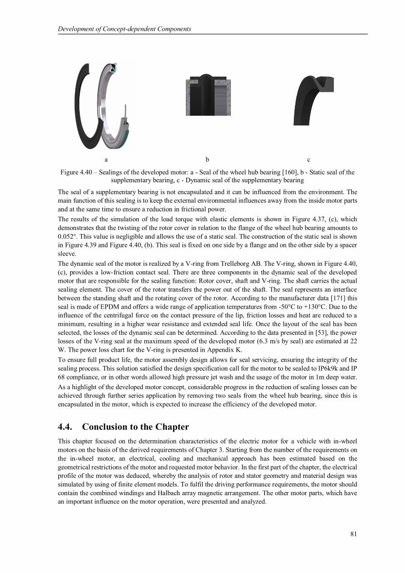
Development of Concept-dependent Components
81
a b c
Figure 4.40 – Sealings of the developed motor: a - Seal of the wheel hub bearing [160], b - Static seal of the
supplementary bearing, c - Dynamic seal of the supplementary bearing
The seal of a supplementary bearing is not encapsulated and it can be influenced from the environment. The
main function of this sealing is to keep the external environmental influences away from the inside motor parts
and at the same time to ensure a reduction in frictional power.
The results of the simulation of the load torque with elastic elements is shown in Figure 4.37, (c), which
demonstrates that the twisting of the rotor cover in relation to the flange of the wheel hub bearing amounts to
0.052°. This value is negligible and allows the use of a static seal. The construction of the static seal is shown
in Figure 4.39 and Figure 4.40, (b). This seal is fixed on one side by a flange and on the other side by a spacer
sleeve.
The dynamic seal of the motor is realized by a V-ring from Trelleborg AB. The V-ring, shown in Figure 4.40,
(c), provides a low-friction contact seal. There are three components in the dynamic seal of the developed
motor that are responsible for the sealing function: Rotor cover, shaft and V-ring. The shaft carries the actual
sealing element. The cover of the rotor transfers the power out of the shaft. The seal represents an interface
between the standing shaft and the rotating cover of the rotor. According to the manufacturer data [171] this
seal is made of EPDM and offers a wide range of application temperatures from -50°C to +130°C. Due to the
influence of the centrifugal force on the contact pressure of the lip, friction losses and heat are reduced to a
minimum, resulting in a higher wear resistance and extended seal life. Once the layout of the seal has been
selected, the losses of the dynamic seal can be determined. According to the data presented in [53], the power
losses of the V-ring seal at the maximum speed of the developed motor (6.3 m/s by seal) are estimated at 22
W. The power loss chart for the V-ring is presented in Appendix K.
To ensure full product life, the motor assembly design allows for seal servicing, ensuring the integrity of the
sealing process. This solution satisfied the design specification call for the motor to be sealed to IP6k9k and IP
68 compliance, or in other words allowed high pressure jet wash and the usage of the motor in 1m deep water.
As a highlight of the developed motor concept, considerable progress in the reduction of sealing losses can be
achieved through further series application by removing two seals from the wheel hub bearing, since this is
encapsulated in the motor, which is expected to increase the efficiency of the developed motor.
4.4. Conclusion to the Chapter
This chapter focused on the determination characteristics of the electric motor for a vehicle with in-wheel
motors on the basis of the derived requirements of Chapter 3. Starting from the number of the requirements on
the in-wheel motor, an electrical, cooling and mechanical approach has been estimated based on the
geometrical restrictions of the motor and requested motor behavior. In the first part of the chapter, the electrical
profile of the motor was deduced, whereby the analysis of rotor and stator geometry and material design was
simulated by using of finite element models. To fulfil the driving performance requirements, the motor should
contain the combined windings and Halbach array magnetic arrangement. The other motor parts, which have
an important influence on the motor operation, were presented and analyzed.

Development of Concept-dependent Components
82
In order to guarantee the required electromechanical output characteristics of the developed motor, as well as
to protect the motor from thermal damage and the components installed inside the motor, the analysis of the
active fluid cooling system was presented. The results contain the developed subsequence for the motor cooling
and optimal geometry of the cooling channel, analytical and numerical results of simulation of pressure loss
characteristic, flow velocities and heat transport of the developed motor. The conclusion of the analysis results
in an effective heat removal and homogenous temperature distribution.
Assuming an electric and a cooling profile, the mechanical profile of the motor was presented. Due to the
topological highlights, the substitution model of the wheel hub bearing was presented first. In addition, the
calculation of the supplementary bearing showed that the requirement on the maximum service life of the
bearing is satisfied. Therefore, the decoupling of the loads in the motor is requested. This challenge is
successfully solved by using the developed coupling element. For the evaluation of the function of the coupling
element, the critical load case scenarios on the in-wheel motor were analyzed. The use of the finite element
method delivered information about the behavior of parts of the coupling element under maximal mechanical
loads. Due to the elastic design, a compensation of the forces acting in the in-wheel motor is realized. On the
basis of the presented analysis, methods and calculations, the structural integrity of the motor shaft can be
examined. Finally, the sealing system of the motor is considered, whereby the amount of losses caused by the
sealing is expected to be minimal. Based on the obtained data, a detailed 3D-model of the developed motor
was built (see Figure 4.41). In the next steps, the electric motor has to be produced to realize the presented
approaches in physical prototypes.
Figure 4.41 – 3D-model of the developed motor

Application Specific Design
83
5. Application Specific Design
The production of the electric motor is characterized by the application of a wide variety of manufacturing
technologies. Apart from the conventional manufacturing methods for the production of motor components,
there are also technologies and processes available that can always provide specific know-how in the field of
electric motor production. This chapter focuses on the special factors of manufacturing and determination of
the manufacturing of the full-scale motor in order to further validate the findings of this research. Based on the
simulation results, topology-optimized design and material data, the technological methods for manufacturing
of the developed motor from analyzed materials are defined. In the following, an implementation of the specific
design for the developed solutions of the electric motor according to Chapter 4 is carried out. The application
refers to the following motor components: rotor including magnets montage, stator main body, stator active
parts: back iron, windings for combined winding and its connection.
5.1. Rotor with Magnets
According to the requirements on the lightweight design of the developed motor, the materials of the rotor
were standard aluminum alloy, aluminum foam and sandwich consisting of CFRP plates and aluminum foam.
Within the first step, the rotors made of full aluminum foam were checked to ensure that the rotor cylinder was
concentric (see Figure 5.1). The rotor, which was made completely of aluminum foam plates, proved to be
dimensionally inaccurate due to casting distortions and was therefore not suitable for further processing. The
measured values have shown that the technology must be further improved in order to maintain the application
for the developed in-wheel motor.
a b
Figure 5.1 – Full aluminum foam variant of the rotor (a) and the results of its run-out measurement (b)
The placement of the necessary magnets (Figure 5.2) to form the Halbach array arrangement with prototypical
devices in the variant made of non-full aluminum foam led to a geometric distortion in the prototype. As a
result, the rotor cylinder of the non-full aluminum foam variant showed deviations in the radial runout.

Application Specific Design
84
a b
Figure 5.2 – Non-full aluminum foam variant of the rotor (a) and the results of its run-out measurement (b)
In addition, it is necessary to perform an optimization loop in the form of a mechanical redesign of the foaming
molds in order to maintain the high tolerances on shape and position while taking into account the production-
related distortion. Both metal foam variants offer a high application potential, whereby the full aluminum foam
variant enables a weight reduction of approximately 25% compared to the standard aluminum alloy version.
Furthermore, in the sandwich variant, the spongy surface of the aluminum foam of the rotor cylinder did not
allow the adhesive to remain on the rotor surface in sufficient quantity. For this reason, the main disadvantage
of using aluminum foam in this variant is the reduction of the surface on which the adhesive material must
provide a carrier film. Therefore, in order to validate the motor concept, the magnets were glued into the rotor
variant made of standard aluminum alloy.
As previously determined, an arrangement according to Halbach was specified for the reduction of the total
weight. Apart from the weight reduction of the rotor unit, however, it is relatively more complicated to
assemble and install than the traditional dipole arrangement. The manufacturing complexity results from the
placement and mounting of the permanent magnets on the rotor cylinder. According to the placement of the
magnets, the developed radial-flux motor uses the principle of surface mounted permanent magnets, in which
the magnets are fixed to the inner rotor surface. The adhesive technique was chosen for fixing the magnets in
the rotor, whereby the different adhesive variants were investigated according to the requirement profile.
During the selection of the glue, the main focus was on the adhesive force on the glued surfaces, the strength
at maximum temperatures and the shear strength. The influence of aging after long-term thermal and dynamic
stress was eliminated. The magnets were glued in a manual way and with the help of special devices. The high
forces that arise between differently polarized magnets have caused the development of the gluing device (see
Figure 5.3, (a)). For this purpose, a series of experiments were carried out, which led to different concepts for
the gluing of the magnets. As a preferable variant, a special device has been developed in which, on the first
step, a simultaneous distribution of the radially magnetized magnets of the first row is realized and the gluing
of the second row of tangentially magnetized magnets is carried out when the glue of the first row is dried, as
shown in Figure 5.3, (b). This device has proven as successful and the further mounting of the magnets was
realized with the assistance of it.
a b
Figure 5.3 – Gluing device for the Halbach array (a) and subsequence of the gluing of the magnets (b)
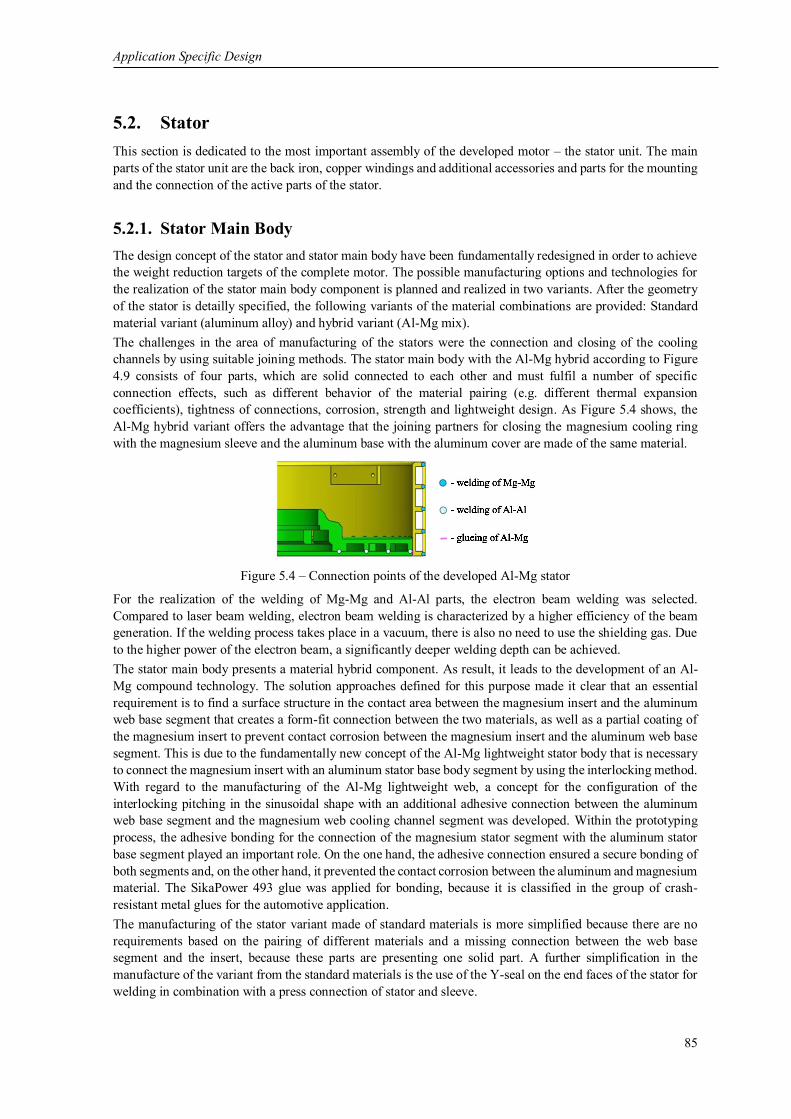
Application Specific Design
85
5.2. Stator
This section is dedicated to the most important assembly of the developed motor – the stator unit. The main
parts of the stator unit are the back iron, copper windings and additional accessories and parts for the mounting
and the connection of the active parts of the stator.
5.2.1. Stator Main Body
The design concept of the stator and stator main body have been fundamentally redesigned in order to achieve
the weight reduction targets of the complete motor. The possible manufacturing options and technologies for
the realization of the stator main body component is planned and realized in two variants. After the geometry
of the stator is detailly specified, the following variants of the material combinations are provided: Standard
material variant (aluminum alloy) and hybrid variant (Al-Mg mix).
The challenges in the area of manufacturing of the stators were the connection and closing of the cooling
channels by using suitable joining methods. The stator main body with the Al-Mg hybrid according to Figure
4.9 consists of four parts, which are solid connected to each other and must fulfil a number of specific
connection effects, such as different behavior of the material pairing (e.g. different thermal expansion
coefficients), tightness of connections, corrosion, strength and lightweight design. As Figure 5.4 shows, the
Al-Mg hybrid variant offers the advantage that the joining partners for closing the magnesium cooling ring
with the magnesium sleeve and the aluminum base with the aluminum cover are made of the same material.
Figure 5.4 – Connection points of the developed Al-Mg stator
For the realization of the welding of Mg-Mg and Al-Al parts, the electron beam welding was selected.
Compared to laser beam welding, electron beam welding is characterized by a higher efficiency of the beam
generation. If the welding process takes place in a vacuum, there is also no need to use the shielding gas. Due
to the higher power of the electron beam, a significantly deeper welding depth can be achieved.
The stator main body presents a material hybrid component. As result, it leads to the development of an Al-
Mg compound technology. The solution approaches defined for this purpose made it clear that an essential
requirement is to find a surface structure in the contact area between the magnesium insert and the aluminum
web base segment that creates a form-fit connection between the two materials, as well as a partial coating of
the magnesium insert to prevent contact corrosion between the magnesium insert and the aluminum web base
segment. This is due to the fundamentally new concept of the Al-Mg lightweight stator body that is necessary
to connect the magnesium insert with an aluminum stator base body segment by using the interlocking method.
With regard to the manufacturing of the Al-Mg lightweight web, a concept for the configuration of the
interlocking pitching in the sinusoidal shape with an additional adhesive connection between the aluminum
web base segment and the magnesium web cooling channel segment was developed. Within the prototyping
process, the adhesive bonding for the connection of the magnesium stator segment with the aluminum stator
base segment played an important role. On the one hand, the adhesive connection ensured a secure bonding of
both segments and, on the other hand, it prevented the contact corrosion between the aluminum and magnesium
material. The SikaPower 493 glue was applied for bonding, because it is classified in the group of crash-
resistant metal glues for the automotive application.
The manufacturing of the stator variant made of standard materials is more simplified because there are no
requirements based on the pairing of different materials and a missing connection between the web base
segment and the insert, because these parts are presenting one solid part. A further simplification in the
manufacture of the variant from the standard materials is the use of the Y-seal on the end faces of the stator for
welding in combination with a press connection of stator and sleeve.

Application Specific Design
86
a b
Figure 5.5 – Variants of the stator: standard material variant (a) and hybrid variant (b)
Design concepts of the developed cooling system were successfully implemented in both stator variants. The
system of connecting the stator web (with cooling channels) and the outer sleeve was implemented as a liquid-
tight solution. As a result, a two-piece stator made of aluminum and magnesium alloy and one-piece stator
made of aluminum alloy were manufactured. The application of the hybrid stator main body allows to reduce
the total weight of the stator by 15% in comparison to the standard material design.
5.2.2. Back Iron
In the following, the mounting of the back iron on the stator is explained. For the safe torque transmission, the
surface pressure by shrinking the back iron was selected. For the stator assembly, a press fit between the back
iron and the stator was selected. It was realized by shrinking during the heating of the back iron and
simultaneous cooling of the stator (see Figure 5.6, (a)). To achieve shrinkage, calculations according to [39]
were performed in the area of tolerances, which makes the joining process technologically more demanding.
Nevertheless, even in these accuracy classes it is considered to be accepted in electrical engineering. The
connection of parts by shrinking is necessary because other methods (e.g. gluing) cannot provide optimum heat
dissipation of defined areas due to the formation of air cavities and relatively low thermal conductivity of glue.
The back iron is produced by conventional processes for electrical engineering – the bounding process. To
increase the active bonding surface for baking the sheets in the back iron, an additional outer ring was attached.
The additional ring is shown in Figure 5.6, (b). It prevents the sheets from falling into pieces when the back
iron is mounted. The function of the ring is to increase the stability of the back iron and to provide the centering
of the sheets by using the holes in the ring during bonding. Therefore, the ring complicates the manufacturing,
because it had to be removed after the back iron is placed on the stator. Due to the switch-off, the partial short-
circuit of the plates are in the tooth head area and a certain increase of the eddy current losses in the plates can
be expected. And the eroding process was used to cut the ring. The cutting by eroding is relatively fine. It
results in less eddy currents losses, because it allows to reduce the number of contact points between the sheets.
a b
Figure 5.6 – Cooling of the stator by shrinking (a), mounted stator and back iron with additional ring (b)

Application Specific Design
87
For the calculation of the undersize for the shrinking process, a temperature of the back iron of 150°C and
temperature of the stator main body of -30°C was assumed. The expansion coefficients of aluminum and NO20
steel are 𝛼𝐴𝑙 = 23.8∙10-6 1/K and 𝛼𝑁𝑂20 = 11∙10-6 1/K. Thus, for the expansion of the back iron of ∆𝑏𝑖 = 0.50
mm and constriction of stator main body of ∆𝑠𝑡 = 0.39 mm. The difference equals 0.45 mm, which enables the
assembly of the stator and the back iron using manual devices.
Shrinking as a technology for mounting the back iron has shown that, if the interference fit for torque
transmission between back iron and stator is sufficient, it is also suitable for certain thermal load scenarios.
The validation of the thermal conditions between the stator main body and back iron can be performed after
the mounting of the windings. As a further development, the tolerance which allowed a larger press fit could
be chosen. Another approach that simplifies the thermal load on the back iron is to cool the stator with liquid
nitrogen instead of heating it. The heat conduction can also be improved by the use of heat conducting greases.
5.2.3. Windings
The winding technology can be classified into the manufacturing process of joining through forming. In this
process, a wire is continuously bent to produce a coil. In order to bend the wire into a coil, different winding
types and processes are used. A winding type describes the way the winding material is placed in or on the
back iron. The type of winding depends on the requirements of the product, such as the fill factor or production
costs. Techniques like wild, orthocyclical, helical, cross or toroidal winding are well known for individual and
mass production for various types of electric motors. The meander-shaped combined winding consisting of air
gap and slot winding differs significantly from classic winding forms and provides a cutting-edge technology
for the application in electric motors.
In order to better understand the effects of new winding concepts and the potential of its manufacturing, the
following case of implementation was carried out. The following section represents a new winding concept,
which is associated with a specific design and novel manufacturing steps. For the implementation of this
concept, basic practical work was carried out until the completed laboratory prototypes were provided for
analysis and validation of the motor parameters. The investigations were performed on the process of winding
the slot winding, following closing of the slots in the back iron, winding of air gap winding on the stator and
wiring the windings.
5.2.3.1. Slot Winding
Pyrhonen et al. [140] defines the part of the winding located in a single slot as a coil side, and the part of the
winding outside the slot is termed a coil end.
The windings are realized in such a design (see also below following winding process of the air gap winding)
that the relatively short connection between the individual coil sides and the coil ends of the winding phases is
arranged. The coil ends represent the connection between the coil sides or the phase wires with the shortest
possible path of the spatial arrangement, so that alternating current flows in the adjacent phase can be realized.
Alternating current flows are defined as the current that changes its orientation between the adjacent phase coil
sides, which are connected by coil ends. Thus, all magnets can be used simultaneously for the torque
generation. Short coil ends keep the ohmic losses low and therefore increase the efficiency of the motor.
In case of the developed slot winding, the windings are pre-manufactured as finished elements and can be
mounted into the back iron of the stator. For the winding of the slot winding, a winding scheme has been
developed, which is illustrated in Figure 5.7, (a). According to the developed scheme for a better understanding
of the winding process, the CAD model of the slot windings was established (see Figure 5.7, (b)).

Application Specific Design
88
a b
Figure 5.7 – Winding scheme of the slot winding (a) and CAD of the slot winding (b)
The axial length of the coil ends has been analyzed by the variation in the arrangement of the wires in the CAD
models and the twisting of the wire outside the slot. The following lengths were obtained for the investigated
versions of the coil ends: Strict bended ends of 3.6 mm (Figure 5.8, (a)), twisted ends of 5.2 mm (Figure 5.8,
(b)) and rounded ends of 5.6 mm (Figure 5.8, (c)).
a b c
Figure 5.8 – Variants of the coin ends: a - Strict bended, b - Twisted and c - Rounded
Although rounded coil ends are the longest, they are the most acceptable in terms of prototype production and
require the minimum of technological complexity in their manufacturing.
For meander-shaped windings, a special device was developed. The device for coil ends represents a board
with 56 slots and 56 pins. The pins provide the shape for the winding end. The free ends of the winding must
be sufficiently long (app. 60 mm) to be able to make the phase connections later. The configuration of the
developed device and an example of the pre-shaped winding is shown in Figure 5.9.
a b
Figure 5.9 – Device for the pre-shaping of the slot windings (a) and bended windings of the slot winding (b)
In order to provide insulation and prevent the damage of the wires against the sharp edges of the back iron,
the endcap for the front sides have been developed. The endcaps (see Figure 5.10) are made from polyamide
using the Rapid Prototyping technique (SLS) and glued to the front side of the back iron.
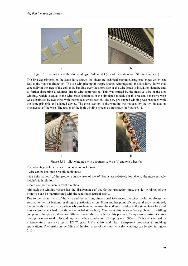
Application Specific Design
89
a b
Figure 5.10 – Endcaps of the slot windings: CAD model (a) and realization with SLS technique (b)
The first experiments on the stator have shown that there are technical manufacturing challenges which can
lead to the motor malfunction. The test with placing of the pre-shaped windings into the slots have shown that
especially in the area of the coil ends, bending over the short side of the wire leads to insulation damage and
to further disruptive discharges due to wire compression. This was caused by the massive wire of the slot
winding, which is equal to the wire cross-section as in the simulated model. For this reason, a massive wire
was substituted by two wires with the reduced cross-section. The new pre-shaped winding was produced with
the same principle and adapted device. The cross-section of the winding was reduced by the two insulation
thicknesses of the wire. The results of the both winding processes are shown in Figure 5.11.
a b
Figure 5.11 – Slot windings with one massive wire (a) and two wires (b)
The advantages of the two-wire version are as follows:
- wire can be bent more readily (coil ends),
- the deformations of the geometry in the area of the 90º bends are relatively low due to the more suitable
height/width relation,
- more compact version in axial direction.
Although the winding variant has the disadvantage of double the production time, the slot windings of the
prototype can be manufactured with the required electrical safety.
Due to the natural twist of the wire and the existing dimensional tolerances, the wires could not always be
secured to the slot bottom, resulting in positioning errors. From another point of view, as already mentioned,
the coil ends are thermally particularly problematic because the coil ends overlap at the stator front face and
thus cannot be attached directly to the cooled stator body. One possibility to solve both problems is a filling
compound. In general, there are different materials available for this purpose. Temperature-resistant epoxy
casting resin was used to fix and improve the heat conduction. The epoxy resin SKresin T4 is characterized by
a temperature resistance up to 120°C, good UV stability and clear, transparent properties in molding
applications. The results on the filling of the front areas of the stator with slot windings can be seen in Figure
5.12.

Application Specific Design
90
Figure 5.12 – Filling of the front areas of the stator
5.2.3.2. Inlays
In the field of inlays for the slots, different approaches for filling were investigated. In terms of geometry and
material, the preferable inlays variant was already defined in 4.1.2.3. The first tests were carried out using the
same material (electrical steel NO20) that was used for simulations and to manufacture the back iron. An
aluminum sheet, as a non-magnetic material, was chosen as the core of the sandwich of the inlay. This sheet
can be easily deformed when the inlay is inserted, thus compensating for shape differences of the back iron is
provided. Tests have shown that this is the best solution for the oversized inlay, i.e. the insertion of the wires.
The insulation of the down surface of the inlay is achieved by inserting the paper strips made of Nomex® as a
cover strip over the wires in the slot.
Subsequent to the manufacturing tests it was determined that the preferred NO20 version could not be
manufactured, as it consisted of five separate metal strips, each of which had to be handled and fixed
individually. After investigating alternative cutting technologies, it was also discovered that the manufacturing
of such fine metal strips is very complicated and the cut inlays have internal stresses and occasionally burrs.
These two aspects make the installation of the inlay extremely difficult and directly affect the main function of
the motor. However, for the series production it offers high potential, especially if the sheet metal strips are cut
off from the sheet or coil.
In the next step, a casting technology was developed as a technologically simpler equivalent for the solid inlay.
In this variant, the filling of the slots was investigated, whereby a compound of iron particles and epoxy resin
was produced in various proportions. The relative permeability 𝜇𝑟 of the potting in the solid state must be
configured in such a way that the cogging torque is minimized, but at the same time the back EMF is not
degraded. Furthermore, the compound must have the required dielectric strength values. The stator slots were
completely filled with the potting material (see Figure 5.13, (a)). Afterwards, the rests on the stator were
removed by grinding. The measurements of the compounds have shown that the values of permeability 𝜇𝑟 are
about 11, which modifies the cogging torque of the motor very slightly.
The further experiment of reducing the cogging torque was investigated by filling the slots with a defined flux-
suppressor film from Kemet. The advantage of the film is its relatively high flexibility, which facilitates the
installation of the inlay. The permeability value 𝜇𝑟 of such a film according to the manufacturer is about 130,
which should lead to a significant reduction of the cogging torque. The structure of the inlay of the used
sandwich made of the films represents Figure 5.13, (b).

Application Specific Design
91
a b
Figure 5.13 – Filling the slots with compound (a) and structure of the inlay with flux-suppressor of Kemet
After completion of the slot filling, the back iron should be grinded in order to achieve a defined roughness.
This provides a continuous surface which simplifies the implementation of the winding on the stator.
5.2.3.3. Air Gap Winding
In view of the innovation of the technology, the special feature of the motor with air gap winding is the
meandering form of the individual phases of the winding. Therefore, the application of the air gap windings is
a major problem for the implementation of the motor concept. In joining technology, force-fit and form-fit
joining processes are fundamentally excluded, since one of the motor's priorities is to place only the winding
in the air gap.
The wires of the air gap winding have to be applied in one layer around the stator circumference on the outer
surface of the cylinder. This means that each wire must be connected to the stator. The manual application of
the windings on the stator outer surface is a very time-intensive and fault-sensitive process. A large number of
movements around different axes have to be performed to implement this process. For this reason, an automated
process is required for economic use. According to [23], for this purpose a winding machine was developed
and designed. The machine has 13 axes to provide all positioning movements that are necessary for the winding
application process. An application of the machine gives an opportunity of handling a wide range of stator
diameters, stator depths, number of wires, number of phases, wire geometries, and winding connections [23].
The structure of the winding machine can basically be divided into six assemblies, see Figure 5.14:
- table consisting of aluminum fixing profiles,
- coil carrier with threaded rods,
- wire feed mechanism,
- portal with actuators,
- the control system (located under the machine table) with a PC for command input.
Figure 5.14 – CAD of assembled winding machine [23]
The operation of the winding machine could be described in the following steps:
- the prepared stator is mounted with the help of the flanges and installed in the portal of the winding machine;

Application Specific Design
92
- the single wires are fed off the coils and passed through the wire feed to the stator. The tension of the
individual wires is adjusted by four bolts on the wire feed, which press the felt mats together;
- at the output of the wire feed, the wires are packaged through the clamps;
- the end of the package is fixed after the portal of the winding machine;
- the wires have to be cleaned before bonding;
- the wire package is pressed onto the surface of the stator with the help of a downholder. Thus, the wire
package is bonded and held;
- on the front side of the stator a pin is placed by a linear drive;
- the coil end will be produced, whereby the stator is rotated by 180° around its vertical axis;
- to obtain the correct shape of the coil end, the overbending process should be provided by an additional
rotation of +30° and then -30° around the vertical axis;
- the second downholder device is driven so that the second winding package is pressed onto the stator surface;
- the coil end can be bent with maximum angle to the stator front side;
- first and second downholders can be raised and the wire packages are relieved;
- the stator can be rotated around its axis at an angle 𝜃𝑝𝑝. The angle 𝜃𝑝𝑝 results from the number of the coil
ends of the phase;
- the winding of the one phase contains 112 coil ends (56 left and 56 right). Therefore, the process must be
repeated 112 times.
For every wire of the motor, a voltage is induced due to self-induction. According to Lenz's law, this voltage
prevents the current from flowing through the wire. In the standard wire arrangement, the magnetic fields of
the individual cores are different in magnitude, which means that a compensating current is generated within
the conductors, since they are connected together at the beginning and the end. As a result, an internal cross
current is produced inside the wire package, which cannot be detected from the outside. Cross currents in the
phases are reducing the maximum rated current of the motor. The required maximum of the torque cannot be
achieved. To eliminate these disadvantages, it is necessary to compensate for the unequal potential distribution.
By a selective wire replacement, the wires should be uncoiled in alternating sequence so that the wires are
positioned once at each position in the wire package on the full circumference of the stator. The number of
wire changes depends on the number of wires used in the winding package. For eight wires, the wire exchange
should be conducted seven times. Wire replacement describes the repositioning of the wire in the wire package
from the inside to the outside of the package. The wire replacement must be carried out solely in the area of
coil ends, because the phases must be as flat as possible and parallel to the axis of rotation and are not allowed
to have a higher dimension in the air gap of the motor.
The bending of the coil ends creates the internal stresses in the bended wires. This leads to wire packets or
individual wires being taped off the stator surface. For this reason, the bandaging of air gap winding is
necessary. The air gap winding bandaging could be realized on the winding machine, where the tensioned
bandage band is fixed by a continuous rotation of the stator. The results of the completed air gap winding
before and after bandaging can be seen in Figure 5.15, (a), (b).
a b
Figure 5.15 – Air gap winding before (a) and after bandaging (b)

Application Specific Design
93
5.2.3.4. Connection of Phases
The connection of phases is an important factor for the correct motor operation. The wrong connection can be
responsible for faulty current flows, which results in a crucial motor fault. To realize the combined winding
concept, the ends of the air gap and slot windings should be connected as it is illustrated in Figure 5.16.
Figure 5.16 – Phase arrangement of the air gap winding and slot winding
The “-” sign in the presented arrangement corresponds to the direction to the stator bottom, and the “+” sign is
determined as the direction from the stator bottom.
During the connection, the individual phase windings are connected to each other according to the connection
scheme presented in Figure 5.17. The positions for the start and end of the phase windings are selected where
the terminal clamps have the shortest distance to the corresponding contact points. The various connection
methods can be used to realize this scheme. According to the number of phases of the motor, there is the same
number of terminal clamps needed.
Figure 5.17 – Scheme of the connections for realization of the combined winding
Basically, all connection elements are composed of electrical conductors that are insulated from each other.
Copper is typically used as the conductor material while the insulation is provided by an insulation coating. If
this method is used, all connections have to be connected directly to the terminal clamps. Due to the relatively
large dimensions of the standard terminal clamps, the special sub-assembly was developed (see Figure 5.18).

Application Specific Design
94
Figure 5.18 – Developed terminal clamps
The main requirements for the development of terminal clamps were:
- the terminal clamps have to realize the series connection,
- the terminal clamps require a good heat dissipating and at the same time insulated contact to the stator surface,
- the clamps also have to keep sufficient distance to rotating parts.
Terminal clamps have a great potential for cost reduction through standardization, but for optimal use of the
working space in the stator, special terminal clamps are required which have an additional development
requirement.
5.3. Conclusion to the Chapter
Chapter 5 concentrates on the application of the motor specific design of the in-wheel motor. The realized
technologies, which have been used as a basis for the manufacturing concepts, have proven to be
technologically successful. In some cases, the concepts which have been revised during the manufacturing
process also showed to be insufficient (e.g. filling of the slots).
In the area of rotor manufacturing, the full aluminum foam variant and non-full aluminum foam variant of the
rotor versions could not be used due to dimensional inaccuracies during production process. The used rotors
showed different dimensional faults before and after the assembly phase. Furthermore, the quality of the inside
surface is not satisfactory to ensure the fixation of the magnets. The presented light-weight technologies have
considerable advantages in weight reduction, but not sufficient for further application in the in-wheel motor
under test, because the accuracy of the produced parts is not achieved. The manufacturing of the prototypes
was performed with the standard materials. The adhesive bounding was applied for the mounting of the
magnets, whereby the special device for the gluing was developed.
In comparison to the rotor assembly in stator manufacturing, the application of the lightweight design variant
achieved the required result. The applied combination of materials results in a weight reduction of 15% in
comparison to the standard materials.
In the area of the stator manufacturing, the application of the back iron on the stator main body as well as the
production of both windings in particular were a technological challenge. The method of winding
manufacturing, which was developed using the corresponding devices and tools, proved to be fundamentally
applicable, but time-intensive. On the one hand there are partly neither existing technologies nor corresponding
experience on the market in the area of winding technologies, on the other hand the assembly technologies
were found which do not limit the technical properties of the winded stator in its performance (cooling of the
windings). Both requirements were successfully solved by the development of the range of special devices.
The derived method of the mounting of the back iron ensures optimum heat dissipation. Furthermore, the
problem of the electrical insulation of both windings was solved by the intended use of special manufacturing
processes. The solution in the field of connection firstly was presented as the special designed terminal clamps,
which can be optimized by the requirements of higher manufacturing needs.
However, it also became apparent that due to the novelty of the development, a number of questions and
problems could not be clarified with absolute precision in advance. The unknown factors were so significant

Application Specific Design
95
that in some cases, second or third attempts had to be conducted, as by the filling of the slots by different kinds
of inlays.
Based on the experience and results of application steps, the respective prototypes were built and assembled
(see Figure 5.19). The prototypes can be used for tests as the physical model to validate the theoretical
approaches presented within this work.
a b
Figure 5.19 – Assembled variants of prototypes: a - Standard materials, b - CFPR

Experimental Validation
96
6. Experimental Validation
Despite the diversity of existing approaches and the availability of simulation programs, no universal
methodology is being developed that allows a combination of complex processes to be considered by
simulating motors. In accordance with requirements for the efficient manufacturing of the motors, it is
necessary to use validated analytical methods to estimate the important parameters of the motor.
Chapter 6 concentrates on a validation of the developed in-wheel motor as well as on the impact of boundary
conditions and assumptions determined in this study. For this reason, the prototypes were metrologically
evaluated and the measured properties were analyzed. The prototypes were measured in special test stands
regarding their electrical, magnetic and mechanical properties.
In the first part of the chapter the influence of the forces acting on the wheel on the air gap in the special test
stand was presented for validation. Afterwards, the losses due to existing cogging effects are presented and
analyzed, whereby the proposed filling principles for the validation of different possibilities of minimizing the
cogging effect were tested with the help of a specially developed test stand. The motor parameters represent
the essential and important knowledge about its function before the test of the motor on the test stand began.
After the preliminary tests of the prototypes were carried out, the measurements on the motor test stand are
presented. In the final section, the validation of the required parameters regarding the weight of the in-wheel
motor and potentials of the lightweight design are introduced.
6.1. Air gap changing
This section presents the validation and comparison between analytical results and test results using the
approach that uses a specially designed test stand.
6.1.1. Approach of validation
To inspect the mechanical structure of the developed motor and the principle of decoupling the forces, a special
test stand was developed to assess the static load cases according to the requirements.
As illustrated in Figure 6.1, the test stand consists of the following subassemblies: clamping unit, frame, angle
support, hydraulic cylinder and 6-axis force sensor. The wheel alignment on the developed test stand is
horizontal. The load is generated hydraulically and is applied to the wheel by the hydraulic cylinder via the
clamping unit. The clamping unit holds the wheel flange, it also should be complied with the shape of the
wheel and equally distribute the load over the contact surface. The load can be determined approximately by
comparing a pressure measurement. The precise measurement of the forces is performed by the 6-axis force
sensor, which is installed directly in the clamping unit. The lifting forces can be generated with corresponding
hydraulic cylinders up to 100 tons [111]. The oil pressure required for the hydraulics can be applied via a hand
pump. The measurement of the oil pressure is carried out via the pressure gauge. The frame construction
consists of the profiles connected with each other with screws, which enables quick rebuilding for different
modifications of the test objects. With the help of this test stand, it is possible to test the in-wheel motor wheels
with different diameters and widths (see Appendix L for details). This can also be done by the stroke of the
cylinder or by the sliding of the hydraulic cylinder. In the frame base plate, there are guide rails on which the
hydraulic cylinder can be adjusted according to the wheel diameter. In addition, different load cases can be
realized by rebuilding the hydraulic cylinder. With radial load, the hydraulic cylinder directly loads the shaft
of the clamping unit. Figure 6.1 shows the case of radial load, in which the direction of force is radial to the
wheel axis.

Experimental Validation
97
Figure 6.1 – Explanation of the main parts of the test stand and scheme of the radial load
During the torque load, the angle support is displaced from the axes of symmetry of the wheel. This results in
a lever arm and a torque can be applied to the wheel via the translational action of the hydraulic cylinder. The
torque load is depicted in Figure 6.2, (a).
The axial load presents a simulation of the lateral forces during cornering. The direction of force is parallel to
the wheel axes of symmetry. This is achieved by mounting the hydraulic cylinder on the frame base plate, see
Figure 6.2, (b).
a b
Figure 6.2 – Scheme of the testing of the torque load (a) and axial load (b)
A laser sensor is used to measure the change in the air gap. Due to the limited space, it is not possible to install
the sensor directly in the motor. Therefore, for the indirect measurement on the stator, an extension was
mounted and the laser sensor was fixed directly on the rotor. The measuring principle described is illustrated
in Figure 6.3.
Figure 6.3 – Extension for the measuring of the variation of the air gap
6.1.2. Measurement Results
By the measurement on the prototype of the developed motor on the shaft flange and on the rotor cover, the
rotation lock device was attached to provide the symmetrical application of the loads.

Experimental Validation
98
The measured courses of force generation were carried out according to the required load characteristic. Since
the static load was measured, the load was stopped after reaching the maximum required value. At the same
time of loading the change of the air gap was recorded. The results of the measurement for all three required
loading cases are shown in Figure 6.4, Figure 6.5 and Figure 6.6.
a b
Figure 6.4 – Development of force (a) and corresponding air gap variation under the axial load (b)
a b
Figure 6.5 – Development of force (a) and corresponding air gap variation under the radial load (b)
a b
Figure 6.6 – Development of force (a) and corresponding air gap variation under the torque load (b)
The values of the corresponding air gap variations have to be correlated, because the measurement was not
directly performed in the air gap. The values shown in Table 6.1 are calculated by eliminating the lever impact
of the extension keeping the rule of the proportionality of the triangle.

Experimental Validation
99
Type of load Variation of the air gap, µm
Results of the simulation Results of the measurement
Axial load 70 62
Radial load 83 53
Torque load 58 51
Table 6.1 – Comparison of the simulated and measured values of the air gap variation
The results of the measurement of the air gap variation are 62 µm by axial load, 53 µm by radial load and 51
µm by torque load, which do not strongly align to the simulated results with a maximum error of 36.1% for the
radial load case. The reason for this discrepancy can be caused by a higher level of the wheel hub bearing
mounted in the prototype.
According to the presented loading cases, it can be seen that the motor is deformed in symmetric relation to
the load. Furthermore, it is apparent that the air gap is more sensible in case of axial load. The reason for this
is the lower stiffness of the hub bearing in axial direction.
The measured displacements between the stator and rotor under the applied loads are larger than the calculated
values. It is caused by the calculation of the motor model with different simplified approaches (e.g. model of
the bearing), which lead to the occurrence of this discrepancy.
6.2. Cogging Torque
The validation of the analytical method is carried out using the specially developed test stand, which allows to
determine the cogging force. The practical value of validation is that during the development of the test stand,
the shortcomings of the motor active parts can be detected in the early stages of the design and it is essential
to improve the validation procedure. In addition, this method allows the use of interchangeable parts with
standard mounting methods, which allows rapid modification of motor parameters and measurements of
various geometric parameters of the motor active parts.
6.2.1. Validation Approach
The test stand has been designed to simultaneously record the values of the detent force depending on the
variable air gap between the stator and rotor parts of the motor or an application of different materials to fill
the slots. The test stand model was created in the CAD package of Autodesk Inventor and was used to determine
the required geometric parameters of the test stand and for implementation in research.
To simplify the design of the test stand, a linear model of the stator and rotor parts was adopted. Thus, the
measured value was not the value of cogging torque, but of the cogging force arising and acting along the
active parts of the motor. In the following, the part of the rotor refers to the magnets and the part of the stator
is a piece of its back iron (see Figure 6.7).
Figure 6.7 – Principle of the test stand with the motor active parts

Experimental Validation
100
The test stand has a portal design. In this design, a relative displacement of the rotor relative to the stator takes
place by the piece of the back iron. An important condition for an accurate measurement of the cogging force
is the deficiency of any effects from the possible slip of the moving parts of the motor and the guided stand
parts. The relative motion between motor parts requires a smooth, stable, precise, and linear characteristic.
Therefore, the air bearing of the PI-glide RB series linear air bearings was adopted for the test stand
implementation, because air bearings are inherently frictionless, they do not exhibit breakaway or running
friction, even under their maximum load. A noncontact design between bearing parts means that they do not
need maintenance and their accuracy will not degrade over time. For the supply of the compressed air in the
air bearing, a standard air preparation module is used.
The relative movement of the parts is realized through an application of stepping motor with threaded spindle
from Nanotec company. The stepper motor works by switching the power supply. Furthermore, it was ensured
that no ferromagnetic materials were used in the area of the measurement in order to avoid measurement
distortions. Due to the limited space of the air bearing for the test stand application, the usage of five poles
according to the Halbach arrangement was chosen.
The measurement of cogging force occurs by the loading of the load cell, that is mounted between the spindle
of the motor and an extension to the movable platform with the test sample. To evaluate the possible variations
of the air gap between active motor parts, the laser sensors are mounted on both sides of the portal.
Figure 6.8 – Parts and units of test stand
For the measured value acquisition during an experiment, the software package LabVIEW and the associated
NI-DAQmx data acquisition software was used, whereby all installed sensors were evaluated simultaneously.
The result of the measurement is the measurement protocol that was generated in LabVIEW.
6.2.2. Measurement Results
Within the first phase of the measurement, the verification of the test stand was realized with an idle condition.
During this test, all disturbances caused by the motor were detected. These values are important for further
measurements, because the disturbances could be subtracted from measured values of the cogging force.
The measurement investigation was performed sequentially on the same test sample. Thus, the possibility of
discrepancies in the results, which may be caused by geometric inaccuracy of the sample itself, was excluded.
The material that was used for the manufacturing of the test sample is NO20 electrical steel, which is equal to
the simulated material. The test sample represents a flattened piece of the stator back iron with the same
geometry parameters as it was used for the simulation of the cogging effect.
For the manufacturing of the test sample, the sheets were lasered with the same contours as by the back iron,
stacked in a special press and pressed together. The test sample was then baked in an oven. The burrs were
removed manually before the measurement was performed.

Experimental Validation
101
The measurement of the test sample without filling in the slots is shown in Figure 6.9. From the force
distribution it can be seen that very high forces of up to 35 N occur at the beginning and at the end of the
measurement. The reason for this high force level is obviously clear and can be explained as follows, since the
area before and after the magnets is not sufficiently investigated. The simulation model is restricted by the
master-slave boundaries, so the magnetic field dispersion is completely missing in the areas before and after
the magnets. Therefore, the forces occurring during the entrance and leaving of a test sample in the magnetic
field are of high importance. And this is why the simulation results in these areas have a very large difference
compared to measured values. Thus, the range of interest by the measurement presents the area which is marked
in Figure 6.9 with “A”.
For the correct positioning of the filling the copper wires were used, which were planned for the slot winding.
For the filling the sandwich (see Figure 5.13, (b) for details) from the in 4.1.2.3 presented material from Kemet
was used.
Figure 6.9 – Force distribution during measurement of the test sample without filling
Figure 6.10 – Force distribution during measurement of the test sample with filling
The most intriguing areas of the measurement are presented in Figure 6.11. From the acquisition of the force
distribution it is definite that the alternating force variation occurs at the same time as for the test sample with
and without a filling of the slot. A further important implication from Figure 6.9, Figure 6.10 and Figure 6.11
is that the filling plays an important role in the reduction of cogging force, as the peak-to-peak values are lower
than in a non-filled test sample.

Experimental Validation
102
Figure 6.11 – Comparison of the range of measurement of the cogging force associated by the slots
The evaluation of the measurement results was performed by finding the minimum and maximum values over
the apparent range of the cogging torque action. The values of interest represent the mean of the peak-to-peak
values for both measurement cases – with and without slot filling. The average mean value of the cogging force
can be calculated according to the following expression (6.1):
𝐹𝑐𝑚_1 =∑ 𝐹𝑐𝑚,𝑖
𝑛𝑝𝑡𝑝
𝑖=0
𝑛𝑝𝑡𝑝
(6.1)
Where 𝑛𝑝𝑡𝑝 stands for the number of peak-to-peak amplitudes per measurement and 𝐹𝑐𝑚,𝑖 is the value of each
peak-to-peak amplitude. For both variants of filling it a remarkable effect can be identified, because the mean
value of the filled test sample amounts to 3.42 N in comparison with the non-filled test sample of 5.65 N. This
demonstrates just how important the filling of the slots is and has a positive effect against cogging force. The
mean value of the cogging force can now subsequently be used to calculate the cogging torque.
The cogging torque for the full motor is estimated by the empirical formula given in Equation (6.2):
𝑇𝑐𝑜𝑔 = 𝐹𝑐𝑚 ∙ 𝑟𝑠𝑡 = 𝐹𝑐𝑚_1 ∙𝑝𝑝
𝑛𝑠𝑡∙ 𝑟𝑠𝑡 (6.2)
The individual cogging torque value of the both test samples eventually resulted in 21.01 Nm for the non-filled
test sample and 12.7 Nm for the filled sample. The motor with the filling of the stator has an almost 39.5%
lower cogging torque compared to the non-filled variant.
A clear trend in the results of the measurement bears a close resemblance to the simulation proposed in 4.1.2.3.
Therefore, the measured values of the cogging torque have certain differences to the simulated model. The
reason for this is, firstly, the differences in the geometry and tolerances of the test sample, and secondly, the
differences in material properties.
In addition, measurements on the test samples were used to track the position of the moving platform with the
signals of the laser sensors. The high stability provided by the air bearing has prevented the keeping of the
movable platform and the measured values of the relative displacements are in the range of less than 0.001.
These values are comparable or lower than the degree of roughness of the measured surfaces and therefore not
considered in the analysis.
6.3. Motor Parameters
In this section an analysis of the motor parameters presented and examined in the previous chapters is carried
out. The prototypes and measuring equipment used for the different tests, settings and parameters are presented
and discussed. Finally, the results of the validation are shown and the achieved motor characteristics are
compared to the simulation results.

Experimental Validation
103
6.3.1. Preliminary Motor Measurements
6.3.1.1. Resistance and Inductance
The purpose of measuring the resistance of motor windings is to identify defects such as defective connections,
errors in the connection scheme, as well as to clarify the parameters used in the calculation and adjustment of
operating modes, regulators and the verification of the calculated motor parameters. Furthermore, the
adjustment of the resistance of each phase is necessary for further evaluation of the ohmic losses and induced
voltages, for this reason the measurement of resistance was carried out separately for all phases, clamping
elements and additional cables. During the measurement of resistance, the temperature of the winding has a
particular importance. For this purpose, the measurement of phase resistances is performed with the GOM-805
measuring device, which also provides the temperature compensation function during the measurement. The
measured values of the three phase resistances are summarized in Table 6.2.
Phase / Winding A B C
Slot Air gap Slot Air gap Slot Air gap
Resistance, mΩ 124.4 113.9 123.3 115.1 121.6 115.0
235.36 240.76 236.81
% from average 0.95 -1.31 0.34
Table 6.2 – Phase resistance measurement results
The importance of the inductance measurement is caused by the aspect of control. A very low inductance of
the developed motor demands a very high switching frequency for the direct PWM control of the motor. This
causes a higher power dissipation and makes it difficult to use standard motor control methods [57]. For this
reason, the inductance must be precisely measured for stable development and taken into account in further
validation. The inductance measurement was carried out similar to the resistance measurement with the help
of the measuring device Sourcetronik ST2827, whereby the phase inductance can be determined by connecting
phase and neutral point. The measurement accuracy of the used device is 0.05% with a resolution of 10 MHz
and allows to perform very precise measurements. It is therefore conceivable that the measurement was carried
out under the hypothesis that the developed motor could be operated at the maximum frequency of 100 kHz,
so that the measurement was carried out at this frequency. The results of the inductance measurement are
collected in Table 6.3.
Phase / Winding A B C
Slot Air gap Slot Air gap Slot Air gap
Inductance, µH 21.85 7.79 20.89 7.86 25.96 7.89
44.42 43.97 44.39
% from average -0.36 0.65 -0.29
Table 6.3 – Phase inductance measurement results
Table 6.2 and Table 6.3 show that the motor has a very balanced winding. The manufacturing of the motor
however leads to some notable compromises, which affected the way the windings were wound, the slot
openings closed and the phase resistance measured. For example, the design performed in the simulation has
one wire with a cross-section of 2.34x1.0 mm and in the prototypes two wires of 1.1x1.0 mm was used. This
change was caused by manufacturing difficulties and reduces the cross-section of the wire for slot winding of
6% from the expected value. An additional aspect of the minor variation of the measurement values is that the
phase winding was produced in manual and semi-automatic form. However, both measurements demonstrate
negligible differences within the range of up to 1.5%, which can be assumed as an insignificant deviation.

Experimental Validation
104
6.3.1.2. Disruptive Strength
The reliability and safety of an electrical motor depends on the quality of insulation between its windings and
the housing of the electrical motor. Any vehicle is operated under relatively difficult conditions. Vibrations,
extreme temperatures, and harsh environmental conditions have a negative impact on the insulation quality and
are increasing the risk of insulation damage. Especially high potential hazards present systems in which the in-
wheel motor is used. In this case, the phase conductors of the motor are significantly affected by vibrations
generated by the suspension. However, failure areas associated with poor insulation quality can occur at any
point in any phase.
The well-known detection method for insulation fault location is based on measuring the voltage between the
neutral point and the motor body. The potential of the neutral point in case of an insulation fault will change
so that an insulation fault can be detected. With this method, insulation faults that may occur in one of the
motor phases cannot be localized, but only the presence of an insulation fault can be determined. Therefore, it
is a common approach to detect defective winding components using serial search. The windings by this
method are disconnected from the DC source and then re-connected one after the other. The appearance of a
common insulation fault signal during the connection of the next phase or phase wire indicates a fault.
This approach can only be used in the verification process of a small number of prototypes, as the method has
several disadvantages. For example, it cannot be successfully applied if an insulation fault occurs only in a
certain stator position relative to the rotor (e.g. radial winding contact of the magnet). Another disadvantage of
this approach is that it takes significant time to reassess all phase wires. The test device must be connected
every time the wires are connected. If the next phase conductor has proved to be correct, the power is
disconnected again and the next phase wire is connected. Hence, it is almost impossible to determine an
emergency lead in a reasonable time, especially for air gap windings with a large number of wires.
For the manufactured prototypes, the phases were checked for a short circuit to the stator already during the
winding processes. After assembling the motor, the inspection was repeated. The inspection was carried out
with a high voltage supply. The stator and phase contact were connected to the DC voltage source. With the
requirement according to [41] at a test voltage of 2300 V, no current from the phase may enter the stator. With
this method not only the disruptive strength according to the requirement for all phases of the two windings to
the stator and against each other was measured, but also all wires under each other were tested. All dielectric
strength measurements were completed positively, as shown in Figure 6.12.
Figure 6.12 – Test on disruptive strength
6.3.1.3. Maximum Temperature
Since the ohmic losses make up the largest part of the total power dissipation of the motor and the liquid cooling
only runs through the stator, only the stator is examined in the thermal measurements, see Figure 6.13, (a). To
heat the winding as evenly as possible, all three phases are connected in parallel and supplied simultaneously.
Thus, the winding is used as a heating resistance in order to simulate the power loss for the real operation
scenario. This approach assists the validation of the expected values for the developed motor. To determine the
power losses and the actual electrical resistance, the input of the current and voltage was measured and

Experimental Validation
105
documented. It should be noted that the winding generates much higher ohmic power loss in real operation and
that the current is never applied constantly to all phases, but always only for one phase of the air gap and one
phase of the slot winding at the same time. During the tests, the coolant constantly passed through the stator at
25°C and at 0.16 kg/s. During the thermal measurements, the current parameter is varied stepwise and changed
every 90 s. Because some components of the stator are only thermally resistant to approximately 125°C, this
temperature should not be reached.
The temperature measurement was realized with two methods. Firstly, the temperature was measured contact-
free with an infrared thermal imaging camera (see Figure 6.13, (b)). This measuring device belongs to the
group of color pyrometers. A model of the TI105 from Fluke was used as the thermal imaging camera. The
second method of temperature measurement comprises the usage of the PT100 temperature sensors at the
winding heads and terminal clamps as feedback for temperature monitoring in the area of the windings and
connections. The winding heads are usually warmer than the winding on the stator because the heads overlap
each other at some points. In the case of combination winding, there is also an additional factor that the slot
winding is already under the air gap winding. This additionally increases the temperature of the winding heads.
The test measurements have shown that the warmest spots in comparison to the winding heads are the terminal
clamps. For this reason, it makes sense to install temperature sensors at the connections of the various windings
to measure the temperature at the stator.
a b
Figure 6.13 – Thermal measurements: a - Test setup for thermal measurement, b - Infrared camera image at a
current of 150 A and a cooling water inlet temperature of 25°C
During the thermal measurement of the prototypes some errors were discovered, which led to the incorrect
water cooling. The main reason for the incorrect water cooling is assumed to be a manufacturing error during
the mounting of the back iron. It is assumed that the geometrical errors of the back iron do not connect the
stator and the back iron correctly and can cause air layers up to 0.1 mm thick between the stator sleeve and the
back iron. Thus, the contact resistance plays a more important role than the actual thermal resistance of the
material, and this parameter depends on the motor layout and manufacturing technology. Due to this problem,
measurements are always carried out at the hottest spot. As a result, the maximum current intensity for the
three phases must not be exceeded. At a cooling water inlet temperature of 25°C, the maximum current of 240
A was achieved. The increase of the measured temperature at the hotspot in the winding on the stator surface
and on the terminal clamp, as well as the varied parameters are shown in Figure 6.14.

Experimental Validation
106
Figure 6.14 – Development of the temperature and corresponding current
The warmest part of the motor was measured with the temperature sensor mounted on the terminal clamp. The
higher thermal load on the terminal clamps is mainly caused by the prototype phase ends, which are partly
standing around in the air and are not connected to the cooling surfaces of the stator. The temperature
characteristics are generally homogeneous over the surface of the stator, but the underside of the stator shows
a delayed heating process, which could be attributed to a gap between the aluminum and back iron. However,
the cooling surface of the stator leads, with further interpolation, to the conclusion that the cooling system can
withstand the most difficult operating conditions of the developed motor in terms of heat generation. However,
the measurement has shown that the cooling system is working correctly and the heat dissipation corresponds
to the expected simulation results.
6.3.1.4. Mechanical Losses
To separate the losses with mechanical origin, the mechanical losses were measured. Here it was ensured that
no iron losses were implemented in the test. In order to determine the losses of the mechanical components,
the electrically active components of the prototypes were completely or partially removed.
For the measurement of the mechanical losses, a special measuring set-up was assembled. Figure 6.15 shows
the test set-up used to determine the bearing friction. A DC motor is used to drive the in-wheel motor. The DC
motor is connected to the in-wheel motor by two torsionally stiff compensating couplings and a torque
measurement shaft. The couplings ensure a vibration-free operation of the torque measurement shaft. A light-
reflecting strip on the coupling enables the measurement of the rotational speed using a digital speedometer.
More detailed description regarding, for example, the measurements on the test set-up are presented in [189].
Figure 6.15 – Set-up for the measurement of mechanical losses [189]

Experimental Validation
107
According to the measurement setup, the losses of the wheel hub bearing were measured separately in the first
step. The run-in and non-run-in curve in Figure 6.16 represents the dependency of the frictional torque from
the rotational speed.
Figure 6.16 – Frictional torque vs. rotational speed for the wheel hub bearing with and without run-in
For design reasons, the measurement cannot be carried out separately for additional bearing and seal. Therefore,
in the second step of the measurement, the additional bearing and the seal were measured together. Figure 6.17
summarizes the results of the measurement of mechanical losses for the developed motor.
Figure 6.17 – Frictional torque of the individual components
The measurements have shown that the frictional torque of bearings and seal is significantly dependent on the
speed. The measured values correspond to the manufacturer's specifications. From the measurement with and
without run-in, it has become clear that the other influences not taken into account also have the temperatures
of the motor parts. Therefore, the friction of the motor bearings must always be assessed in connection with
the operating conditions.
6.3.2. Test Stand and Approach
For the basic investigations of the behavior of the manufactured prototypes, the motor test stand WEKA was
used (see Figure 6.18).

Experimental Validation
108
Figure 6.18 – In-wheel motor without the entire wheel (only outer ring) installed on the test stand
The test stand equipment for the motor layout validation includes DC motor, torque sensor, cardan shaft,
incremental encoder, prototype and holders. The load machine of the test stand is a DC motor, which keeps the
speed of the prototype motor at constant values. The in-wheel motor and the DC motor are coupled by a torque
sensor DR 2212 to measure the torque. The measurement principle of the torque sensor is based on strain
gauges. If a torque is applied, the shaft is subjected to torsion and thus the strain gauges are deformed. Strain
gauges change their electrical resistance even with small deformation. Since in this electrical path the voltage
from the supply to the display unit changes only as a function of the strain gauge resistance, a measuring
voltage proportional to the torque results at the display unit. The torque sensor has a measuring range of ±500
Nm, whereby the maximum expected measuring error is 0.5 Nm.
A cardan shaft connects the torque sensor to the prototype motor via another shaft. The acquisition of the
rotational speed of the motor is measured with an integrated incremental encoder of the type A02H, which can
also be used to determine the relative position in addition to the angular velocity. For stabilization there is a
bracket mounted to the encoder. The speed can be externally monitored with a PC by using the software
LabView.
The motor is attached to a console by a flange connection and fixed with four bolts. The torque is transferred
from the wheel to the prototype as it was conceptualized through the decoupling element mounted on the
prototype and outer ring of the wheel. Cables for the signals of the sensors are led out of the flange connection
and the phase and star point connection cables. The prototype still needs an external cooling water circuit. This
requirement was met with an external, temperature-controlled cooling system from Lauda T7000.
The motor is loaded behind the holder through a three-phase bridge VS-130MT of Vishay. An oscilloscope
with a differential probe and a current clamp is provided to measure the electrical phase parameters.
Therefore, all the relevant equipment is available for measuring the basic characteristic diagrams of the
prototype. The assembled prototypes are first subjected to the basic functional tests of the in-wheel motor. The
further reconstruction of the expected power and torque values during the operation were carried out at the test
stand. For initial operation and testing, the prototypes were tested without power electronics.
6.3.2.1. B-Field
The magnetic field distribution plays an important role in defining the working conditions in the developed
motor, and directly influences the torque performance of the motor. To this end, it is decisive to outline the
experimental results to validate the numerical models.
For this experiment, Chen-Yang CYSJ302C linear Hall effect sensors were used to measure the magnetic field
strength. The Hall effect sensors were glued on the stator cylinder surface. Since the mechanical gap between
the magnets and the winding is only 0.5 mm with applicated air gap winding, measurements were taken on a
stator that was not equipped with an air gap winding. The sensors were positioned on the different places of
the stator surface: on the teeth, on the slot inlay or somewhere between the teeth and slot inlay. No contact
relation between the pins of the sensors and surface of the stator was provided by adhesive foil with Kapton as
an insulating layer. After the sensors are connected and checked, the prototype can be assembled. The

Experimental Validation
109
measurement procedure assumes that the prototype is mounted on a test stand. After setting a constant
rotational speed on the load machine, the measurement can be carried out. The sensor output voltage is
measured with an oscilloscope and differential probe. The used Hall effect sensor has a sensitivity of 50 mV
per 0.055 T. The experimentational set-up of the measurement is shown in Figure 6.19.
Figure 6.19 – Experimentational set-up for the B-field measurement
Due to the almost identical air gap size and sensor height, two of the sensors were damaged after the prototype
was assembled. The remaining four sensors showed a pair of very similar signals, so it is reasonable to use
only two signals from the sensors by the evaluation. Figure 6.20 shows evaluated B-field waveforms observed
for the manufactured prototype respectively.
Figure 6.20 – Graphs of the motor B-field waveforms
The results of the experiments are consistent with the results obtained by numerical modeling in the Ansys
Maxwell environment. The difference between the results of the numerical modeling and the calculation is
about 2-4% depending on the location of the sensor. The possible causes for the differences of the results could
be the varying distances between the magnets due to the manufacturing tolerances or non-homogenic material
properties.
6.3.2.2. Non-load Test
During the non-load test, the proper interaction between the motor parts can be controlled. The correct
operation of the motor will confirm the operation of individual parts, the condition of the friction surfaces, and
the right connections of the windings.
In the generator non-load measurements, the induced voltages at the motor clamps were determined using a
neutral point in dependence on the rotational speed. In this measurement, both the magnitude and the waveform
for the individual phases for each speed presents a useful data. The measurement was made when the load
machine was operated in engine mode and the prototype was tested in generator mode. During the
measurement, the speed controller of the test stand was activated. Therefore, the control unit of the test stand
allows a comfortable starting of the required speed. The setpoint value for the speed was entered over the

Experimental Validation
110
potentiometer. The measurement was undertaken for each phase between the terminal and start point for the
speed vector of 100 rpm to 1000 rpm in 100 rpm steps.
Results of the measured values are presented in Figure 6.21. According to Figure 6.21, the full motor speed
vector and the corresponding induced voltages of the prototype has a linear relationship.
Figure 6.21 – Induced voltages vs. rotational speed
The results show that the amplitudes of the induced voltages in general correspond to the simulated results.
After the comparison of the measured values, it was detected that the difference between the measurement on
the prototype and the simulation is a maximum of 4.7%. The higher value of the induced voltage means that
in the speed range of the motor there is a lower current requirement for the required torque.
As an example, the waveforms of induced back-EMFs at 100 rpm of all three phases were measured with
subsequent evaluation in LabVIEW (Figure 6.22). The digital signal of the incremental encoder was used for
this purpose. According to the method presented by Schmidt [150], this approach reduces the amount of the
data and guarantees an angle-related measurement of the back-EMF for every rotation without any
discretization error.
Figure 6.22 – Measured waveforms of induced voltages at 100 rpm
The results of the measured waveforms on the prototype motor appear to be quite close to the sinusoidal.
The reason for the difference between the measurement on the prototype and the simulation can be reasonably
assumed with the configuration was carried out using 2D-FEM simulation. Therefore, the influence of 3D-
effects on a prototype is not negligible. Another possible reason for the differences in induced voltages can be
an asymmetric shape of the rotor or stator. The manufacturing tolerances could be reflected by the asymmetry

Experimental Validation
111
in the run-out of the rotor or stator. Due to the concentricity, a different voltage magnitude can be induced in
the phases. Manufacturing tolerances of the wires also have a direct influence and should not be excluded.
The last test that can be conducted on the test stand in non-load measurement is the experimental result of the
cogging torque value. As it can be seen from the measurement sample in Figure 6.23, the measured value of
the cogging effect is non-smoothed and vice versa very jagged. It can be noticed, that every peak-to-peak part
of the measured signal corresponds to the area of one filled slot.
Figure 6.23 – Cogging torque versus relative rotor position (sample from the measurement)
An absolute result of the measurement is a cogging torque value with a maximum of 9.8 Nm. The experimental
value for the cogging torque differs from the value previously measured on the test stand by 22.8%. This
significant difference between the two measurements can largely be explained by the fact that the
measurements on the full prototype are more precise, since the number of simultaneously measured filled slots
is the highest possible. However, the measured value of the cogging torque is 53.3% less than the original
calculated cogging torque value.
The final conclusion considering the cogging torque is that the cogging torque can be further improved to be
under the required value of the motor and the usage of the flux suppressor as a filling of the slots provides a
reduction of the cogging torque value as expected. The probable explanation for the difference between the
measured results and simulation results is inequality in the geometrical accuracy and in the material
configuration.
6.3.2.3. Load Measurements and Efficiency
The most effective test method for an electric motor is the one that is as close as possible to the operation
condition. In other words, a full overview of the performance of an electric motor can be provided by testing
the motor under load. For this reason, to measure the motor it is required to run the motor under load and
measure its power usage.
The measurement was performed with the help of the methodology presented in [150]. The ends of the phases
were supplied by the rectifier, which itself was supplied by the power supply unit. The power supply by this
method is used in a four-quadrant operation and has the function as a pure current sink. Thus, for one rotational
speed, different load points can be inspected using the current sink. The power supply for the motor was
provided by two Regatron power supply units. The use of the two power supply units is conditioned by the
necessity to cover the voltage and current level with the help of two power supply units. The test stand allows
to measure the prototype up to a maximum torque of 300 Nm. The maximum torque was limited because the
load machine which was used to measure the prototype was not able to provide the required 600 Nm nominal
torque. During the measurement, the values of the average torque, the rotational speed, the phase current, and
the voltage at the rectifier are obtained. With the help of these measured variables, it is possible to determine
a complete characteristic diagram of the prototype. The selected resolution of rotational speed and current
variation enables to determine the values with the requested accuracy.

Experimental Validation
112
The test plan included the stationary measurement of the speed-torque characteristic of the motor, which was
tested in selected points. To guarantee a high level of accuracy, the current was varied up to 50 A in different
steps (5-10 A). The load current reached a maximum value of 50 A, which is related to the thermal instability
of the terminal clamp connections. The speed was varied from 100 rpm to 900 rpm in 100 rpm increments. It
was not possible to run the power over the full speed/torque range due to the voltage and current limits of the
power supply units. The voltage was measured with a differential probe and current using a current clamp. The
measured values were monitored using a LeCroy digital storage oscilloscope. Figure 6.24 illustrates a range of
measured torque versus phase current for the simulated and experimental variant.
Figure 6.24 – Graph of results of the experiment and simulation of motor torque vs. phase current
The maximum torque produced by the prototype motor was 240 Nm which is 5.1% less compared to the
simulated value of the torque. Thus, an expected motor constant value is 5.06 Nm/A will not be achieved and
an experimentally defined value is dissimilar with a difference of 7.1% to one simulated earlier. Thus, this
value can be extrapolated by the availability of a more powerful power supply and energy source with higher
current/voltage value.
The measured values from the experiment allow to determine the efficiency. Here, the input power is measured
by measuring the current and voltage at the power supply. Concurrently to this measurement, the resulting
mechanical power is captured using a torque measurement shaft and an encoder. The temperatures in the motor
are measured by temperature sensors installed in different critical places of the stator. The measured efficiency
map for a prototype motor is shown in Figure 6.25.
Figure 6.25 – Efficiency map for a prototype motor
In the course of the measurement it was detected that the measured temperatures in the area of the terminal
clamp are higher than expected, therefore the value of the maximum phase current was limited. Figure 6.25
shows that the highest efficiency was achieved with 92.8% in the full load range at a high torque of 125 Nm.
It can be noticed that the reached efficiency at high speeds (>600 rpm) is 89-90%. The reason for the lower
efficiency in this speed range are the load-independent losses that were dominant here due to the lower torque
level.

Experimental Validation
113
As it can be seen from Figure 6.25 and Figure 6.24, the developed motor can fulfill the required characteristics
that were specified in Chapter 3. Unfortunately, the most commonly used speed ranges of vehicles are indicated
as high torque and are in the middle range of speed. This means that the developed motor will be operated in
lower efficiency regions.
Tests have confirmed the motor's high energy performance. The motor's efficiency of 92.8% was measured in
the generator mode under load. However, the measurements also identified a specific heat dissipation problem
of the motor. The "paradox" of the situation in this case is that the developed motor has the maximum
permissible temperatures of the terminal clamps with a rather high efficiency. The reason for this situation is
the concentration of the main part of losses in the stator and a lack of coolant surface development of in a
particular technical design of a prototype – especially in the design of terminal clamps. In the future, possible
technical solutions to increase the cooling surface and reduce overheating of the motor terminal clamps should
be considered more precisely for the developed motor.
6.3.3. Validation of the Weight, Torque and Power
The total weight is a quality feature of the light motor in particular. As it was mentioned above, the weight is
also relevant for the mechanical behavior of the motor. The initial scientific objectives of this work focused on
the fulfilment of an extremely high torque and power density of the motor with low weight. The power and
torque density present a corresponding relation between the nominal value of power or torque to the weight of
the motor.
Within the first step, it is necessary to analyze the total weights of the different units and material variants of
the developed motor. The other parameters are the generated nominal torque value and the nominal power of
the developed motor variant. Using the results of the weighing of the real prototypes and data from the CAD
models, Table 6.4 was completed to compare the weights and designs for the developed motor parts using
lightweight technologies.
Motor assembly
/ Variant
Weights, kg
Standard
materials
Stator:
Al-Mg
Rotor:
Al foam+CFPR
Rotor:
full Al foam
Light weight
variant
Wheel hub
bearing 2.715 2.715 2.715 2.715 2.715
Rotor 3.858 - 3.262 2.850 2.850
Additional parts
of the rotor 3.236 3.236 3.236 3.236 3.236
Stator body 4.100 3.450 - - 3.450
Additional parts
of the stator 6.319 6.319 6.319 6.319 6.919
Total weight, kg 20.228 18.570
Table 6.4 – Weights and designs for the motor parts using lightweight technologies
According to the results for lightweight motor parts showed in Table 6.4, the weight of a variant made of
standard material is 20.228 kg. This is the biggest value of weight caused by using standard materials. The
lowest value of weight delivers the variant in which the full aluminium foam rotor with hybrid stator of Al-Mg
is combined. The weight of the lightest motor variant is 8% lighter resulting from the use of light weight
techniques. Therefore, the torque and power density can be calculated (see Table 6.5).

Experimental Validation
114
Ratio / Variant Standard materials Lightweight hybrid
Torque / weight 27.93 Nm/kg 30.42 Nm/kg
Power / weight 3.46 kW/kg 3.77 kW/kg
Table 6.5 – Torque and power densities
As it was expected, the presented results of torque and power densities demonstrate more satisfactory values
for the variant made with the application of lightweight techniques. The relatively small difference of 8.9%
between standard material and lightweight variant is also contingent on the fact, that the in Table 6.4 and Table
6.5 presented weights are referring to the motor inactive parts like housing (rotor) or main body (stator). The
weight of the motor active parts like magnets or back iron were also reduced or was completely neglected.
6.4. Conclusion to the Chapter
The chapter started with the mechanical test on the variation of the air gap during the required loads on the in-
wheel motor. For this reason, the special test stand was developed that allows to reconstruct the loads acting
on the in-wheel motor during its operation in the vehicle. The measurement results show clear advantages when
using the developed topology and decoupling element with only 0.062 mm or 12.4% of the air gap change at
the maximum load. This provides stability for the essential motor parameters such as the consistency of the
torque, which also affects the smoothness of the vehicle. Therefore, an experimentally determined air gap
changing correlates well with the theoretical approximations calculated in Chapter 4.
The next important motor operation parameter is the cogging torque, which was measured on the specially
developed test stand. An integration of the non-friction air bearing in the test stand enabled precise
measurements without any friction influence. As a result of the experimental studies, a data on the values of
cogging torque for a test sample were obtained. The results of the measurements correlate very strongly with
the simulation, which is presumably due to the differences in the geometry and tolerances of the test sample or
caused by the differences in material properties of the test samples.
Preliminary measurements of the phase parameters showed negligible differences in the range of up to 1.5%,
which can be noticed as an insignificant deviation. These differences are caused by the technological challenges
in the area of the slot winding. Nevertheless, the measured parameters are acceptable considering the manual
and semi-automatic methods of the motor windings manufacturing. The next parameter that was examined is
the disruptive strength, whose maximum value according to [41] was successfully passed. The continuous
power rating of a motor is generally limited by the rate of heat building due to a non-efficient operation and
increase of the heat dissipation. For this reason, the thermal test was conducted. Results of the test are also
applicable for a further load simulation, because several places of the motor still do not have an optimal cooling.
However, the measurement has shown that the cooling system is functioning correctly and the heat dissipation
is in accordance with the expected simulation results.
Subsequently, the measurement of the mechanical losses is presented. The measured values correspond to the
manufacturer's specifications. The results show that the mechanical components as an undesirable side effect
cause the losses, which are much lower than the ohmic losses, though the effect on the motor losses is apparent.
The mechanical losses, which vary over time, must therefore be taken into account at the design stage of the
motor. Otherwise it can lead to the failure of important motor components such as the seal and bearing system.
The absence of complete electronics with the required parameters made it impossible to carry out a full range
of experiments. For this reason, non-load tests were performed in generator mode. In the course of experimental
studies, the calculated values of electric motor parameters were fully confirmed, the dependence of induced
voltage vs. rotational speed, and the expected value of the magnetic field in the air gap was determined. The
induced voltage described in this chapter shows differences of 4.7% compared to the design.
Further measurements of the cogging torque were also carried out, and the results showed a higher reduction
in the cogging torque. This phenomenon can be explained by the fact that the prototype has a much larger
number of filled slots, which results in a more homogeneous torque distribution and less field dispersion,

Experimental Validation
115
compared to the results obtained on a relatively short sample on the test stand for the cogging torque
measurement.
With the measurement on the test stand with load, the functional verification of the prototype of the developed
motor was performed. In order to determine the torque-speed characteristic curve, motor operating data for
different speeds and with different motor loadings on the test stand were obtained. However, despite the
differences in motor geometry, the tested motor prototype was found to have very similar speed and torque
characteristics. For load measurements, the efficiency was determined directly from the impressed power and
the mechanical output power. Based on this data, the efficiency was determined, the maximum of which was
92.8% for the developed prototype. The measurements on the test stand have shown a very good accordance
of the results obtained in previous chapters. In some areas, there are some differences between the simulated
and measured values. Nevertheless, the deviations are relatively small when the tolerances of the
manufacturing process evaluate different components.
The final result of the chapter was firstly the weights of motor prototypes and secondly the values of torque
and power densities. The lightweight construction technologies used to realize the designed in-wheel motor
make it possible to achieve the goal and reduce the total weight of the in-wheel motor to up to 18.57 kg. This
know-how enables to reach the 30.42 Nm/kg torque density and the 3.77 kW/kg power density on the measured
prototype.
The functional verification of the developed motor concept was tested exemplarily with the prototypes. Thus,
the methodology presented in this thesis was successfully validated. The results presented in this chapter
confirm the concept of this research.

Summary
116
7. Summary
To provide a clear structure of carried out research, this dissertation is divided into seven chapters which are
summarized as follows.
Chapter 1 considered the reasons and progression of the reactions of climate protection and presents a short
history of the development of the electrified vehicle.
In Chapter 2 the general drive techniques of the electric vehicle achieved at the present moment with a special
interest on the in-wheel motor is described. A brief overview of the different types of electrical machines and
possibilities of their integration of existing electrical power train concepts are described here, with reference
to the possible solutions using wheel motors. Additional consideration to principal characteristics of the in-
wheel motor and the boundary conditions of the application are discussed and the relevant requirements are
derived. To analyze existing in-wheel motor concepts, a comparison with regard to the gravimetric power and
torque densities and their presentation date are evaluated. Based on the outlined state of the art, the chapter
closes with a problem statement and objective of this work.
In Chapter 3, the requirements on the in-wheel motors are determined. The fundamental requirements for the
development include the step-by-step analysis of requirements for the vehicle, requirements of the topology of
the in-wheel motor, requirements on the elastic coupling, requirements for the electric motor and requirements
on the motor weight. The results of received requirements present a basis for further development.
Chapter 4 is devoted to the development of the in-wheel motor. The development strategy is segmented
between an electrical, cooling and mechanical approach based on the geometrical restrictions of the motor and
requested motor behavior.
Chapter 5 concentrates on the application of the specific design and focuses on the special factors of
manufacturing and determination of the manufacturing of the full-scale motor in order to further validate the
findings of this research. The realized technologies, which had been used as a basis for the manufacturing
concepts, have proven to be technologically successful.
Chapter 6 includes a validation of the developed in-wheel motor as well as the impact of boundary conditions
and assumptions determined in this work. For this reason, the prototypes were metrologically evaluated and
the measured properties were analyzed. The prototypes were measured in special test stands regarding their
electrical, magnetic and mechanical properties.
Summarizing Chapter 7, the aim of the work was to develop innovative solutions for electrified powertrains in
order to further increase the attractiveness and spread of electric vehicles. Technological advances and
increased energy efficiency were achieved by optimizing the main component of the drivetrain – the in-wheel
motor. Important objectives were defined such as mass reduction, compact designs and reduced material use.
Further great potential was found in the structural optimization and the new motor architecture, whereby the
requirement for a compact design was successfully implemented. Due to the relatively small iron content in
the stator, the motor losses are accordingly reduced, which contributes to a very high degree of efficiency and
thus meets the demands for an increased energy efficiency and range. It can be added that in this dissertation a
considerable technological progress was worked out in detail and as a whole, which, through a significant
increase in competitiveness, provides the basis for the development of new technologies in the field of the
electric drive train.
As one of the final statements in reference to the development of the concept of a novel type of winding, the
technical advantages of the lightweight motor were significantly improved. In addition to its low weight, a
major advantage of the motor in terms of compactness is the reduction in the dimensions of the stator. For
example, the motor has a comparatively large interior space and could thus contain various components (e.g.
control system). Based on the experience and results of the application steps, the respective prototypes were
built and assembled. Thus, the practical results of the dissertation are prototypically manufactured and tested
in-wheel motors with reduced weight, a more compact design and performance data that meet the requirements

Summary
117
of the market. The prototypes were used to test the theoretically proposed solutions. According to the
requirements on the motor, a series of the test was carried out. The results of the mechanical tests showed clear
advantages in the application of the developed topology and decoupling element with only 0.062 mm or 12.4%
of the air gap at the maximal load. This provides stability of the essential motor parameter such as the
consistency of the torque, which also affects the smoothness of the vehicle. An electro-mechanical parameter
for the motor, the cogging torque, was successfully reduced with the help of special material and geometric
adjusting. Based on the data from the measurements of the prototypes, the maximum efficiency was determined
to be 92.8%. As the final result of the work, the used lightweight technologies for the realization of the
concepted in-wheel motor were evaluated. An achievable value of torque/weight ratio reaches 30.42 Nm/kg
and the value of power/weight ratio is 3.77 kW/kg. Thus, the methodology presented in this thesis was
successfully validated. The overall system of the in-wheel motor works according to the expected results of
the calculations and simulations on which the concept was based.
Looking ahead, a benchmark analysis with world-renowned and competing in-wheel motors has shown, that
the developed motor technology can replace existing in-wheel solutions and traditional drive systems in the
automotive sector in the future.

Appendix
118
Appendix A
Parameters of Modern-Line single section and modular wheel
Appendix B
Parameters of Goodyear Vector 4 Seasons tire
Parameter Value
Tire width 205 mm
Aspect ratio 60%
Wheel diameter 16”
Load-capacity index 92 (max 630 kg)
Speed index H (max speed 210 km/h)

Appendix
119
Appendix C
Parameters of N45SH material
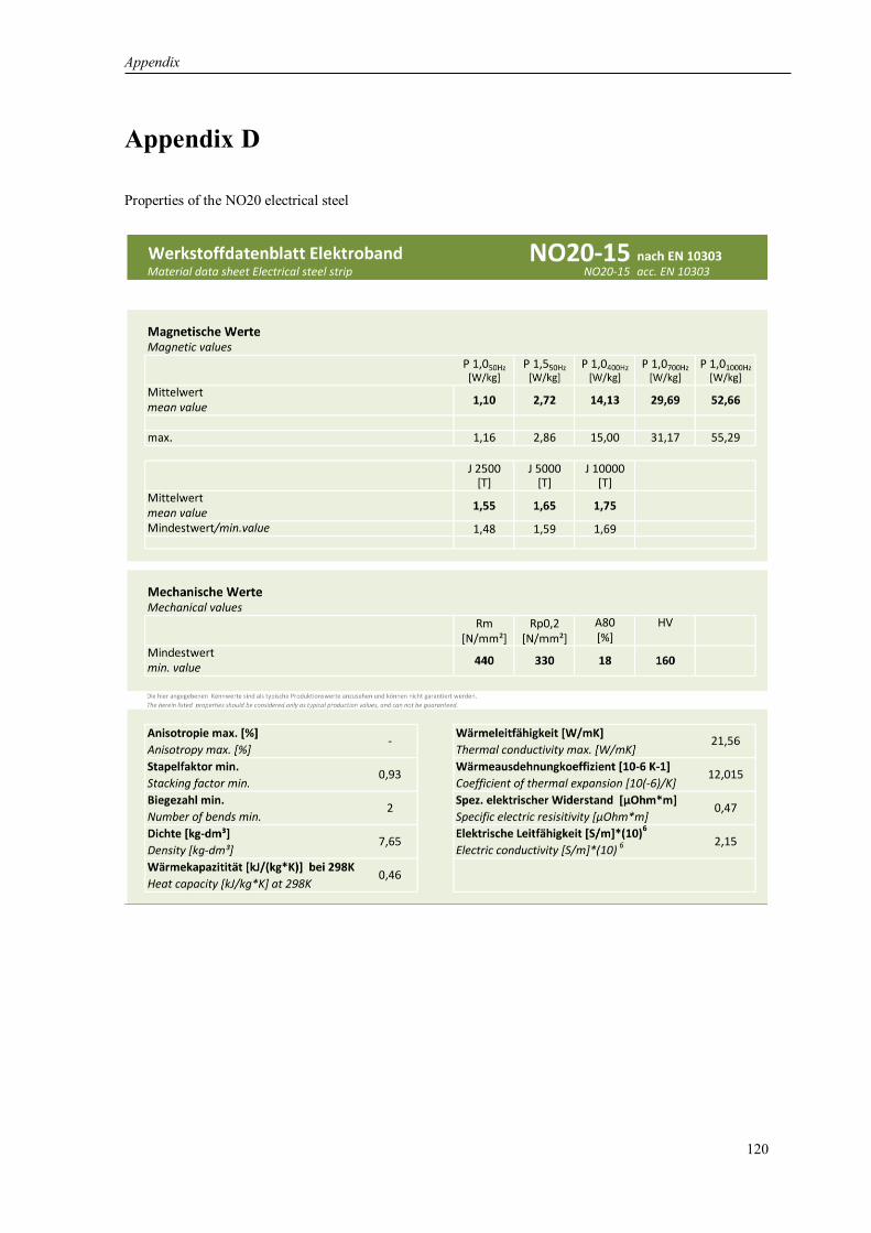
Appendix
120
Appendix D
Properties of the NO20 electrical steel

Appendix
121
Appendix E
Parameters of the foil 70984
Adhesive Carrier film Adhesive
Type Transfer adhesive
Acrylat Kapton 100MT
Transfer adhesive
Acrylat
Article CMC 15581 Kapton 100MT CMC 15811
Adhesive strength 5.5 N/cm 1.0 N/cm
Thickness 0.050 mm 0.025 mm 0.020 mm
Width 140 mm
Appendix F
Parameters of the copper wire and insulation for air gap winding SFT-AIW 0.31x0.94
Item
Conductor
dimension
Thickness of
insulation Overall dimension
Pinhole
Dielectric
breakdown
voltage
Conductor
resistance Thickness Width Thickness Width Thickness Width
Unit mm mm mm mm mm mm Pcs/m kV Ω/km
- 0.31 0.94 0.025 0.025 - -
3 3.0 68.131 max 0.319 1.0 0.04 0.04 0.38 1.045
min 0.301 0.88 0.02 0.02 - -
Parameters of the copper wire and insulation for slot winding SFT-AIW 1.0x1.1
Item
Conductor
dimension
Thickness of
insulation Overall dimension
Pinhole
Dielectric
breakdown
voltage
Conductor
resistance Thickness Width Thickness Width Thickness Width
Unit mm mm mm mm mm mm Pcs/m kV Ω/km
- 1.0 1.1 0.025 0.025 - -
3 3.0 20.84 max 1.03 1.16 0.04 0.04 1.08 1.08
min 0.97 1.04 0.01 0.01 - -

Appendix
122
Appendix G
Properties of bandaging electrical tape 1339
Properties Typical value
Thickness 6.5 mils (0,165 mm)
Breaking Strength 275 lb./in (481 N/10 mm)
Elongation 5%
Adhesion to Steel 35 oz/in (3,81 N/10 mm)
Dielectric Strength 5,500V
Temperature Class 130°C
Insulation Resistance 1x10⁵ megohms
Electrolytic Corrosion Factor 1.0
Appendix H
Typical Electrical Properties of DuPont™ Nomex® 410

Appendix
123
Appendix I
Properties of the material PA 3200 GF

Appendix
124
Appendix J
Determination of the copper losses for various currents
Appendix K
Power loss chart for the V-rings
0
2000
4000
6000
8000
10000
12000
14000
16000
18000
20000
0 25 50 75 100 125 150 175 200 225
𝑃𝐶𝑈
,W
𝐼𝑚𝑎𝑥, A

Appendix
125
Appendix L
Characteristics of the test stand for the measurement of the air gap variation
Testing Maximal load Wheel diameter Wheel width
Radial load 10 kN 13"-22" 5"-12.5"
Axial load 10 kN 13"-22" 5"-12.5"
Torque load 2000 Nm 13"-22" 5"-12.5"

Bibliography
126
Bibliography
[1] G. Abhishek, V. Ramsankar, M. Sreesankaran, G. Sabareesh, N. Jalaiah, "Combined effects of
vehicle body geometry and drag reduction techniques on drag coefficient," in 8th International
Colloquium on Bluff Body Aerodynamics and Applications, Boston, 2016.
[2] ADAC, "Tesla Model S P100D (11/16 - 03/19),"Allgemeiner Deutscher Automobil-Club e.V.
(ADAC), 24.02.2019. [Online].
Available: https://www.adac.de/rund-ums-fahrzeug/autokatalog/marken-modelle/tesla/model-
s/1generation-facelift/261294/
[Accessed 05.12.2019].
[3] W. Adams, "Electric motor". Patent U.S. Patent 300827, 1884.
[4] S. An, Z. Ma, W. Li, H. Zhang, T. Yin, "Magnetic properties of anisotropic bonded NdFeB/SmCo
permanent magnets," AIP Advances, vol. 9, no. 125146, pp. 1-4, 2019.
[5] M. Anderson, D. Harty, "Unsprung Mass with In-Wheel Motors - Myths and Realities," in 10th
International Symposium on Advanced Vehicle Control (AVEC), Loughborough, 2010.
[6] E. Andersson, "Optimization and re-design of a wheel hub to reduce unsprung mass of a rallycross
car," University of Skövde, Skövde, 2018.
[7] M. Ashby, A. Evans, N. Fleck, L. Gibson, J. Hutchinson, H. Wadley, Metal Foams: A Design
Guide, Burlington: Butterworth-Heinemann, 2000.
[8] Automotive Electronics Council, "Failure Mechanism Based Stress Test Qualification for
Integrated Analytical Magnetic Circuits". AEC-Q100-Rev.H, 2014.
[9] B. Becker, J. Rusch, U. Rebholz, T. Buerger, B. Bergrath, S. Geisler, "Abschlussbericht des
Forschungsprojektes Serienfähige, hocheffiziente Radnabenmotoren mit integrierter
Leistungselektronik, SeRiel im Rahmen der Bekanntmachung "Serienflexible Technologien für
elektrische Antriebe von Fahrzeugen," Heinzmann GmbH & Co. KG, Schönau, 2016.
[10] M.-A. Beeck, B. Stoffregen, "Measurement of the Projected Frontal Area of Vehicles, A New
Contour Tracking Laser Device in Comparison to Other Methods," in International Congress and
Exposition, Detroit, 1987.
[11] M. Biček, D. Miljavec, G. Gotovac, S. Zupan, "Mechanical Failure Mode Causes of In-Wheel
Motors," Strojniški vestnik - Journal of Mechanical Engineering, vol. 61, no. 1, pp. 74-85, 2015.
[12] M. Biček, G. Gotovac, D. Miljavec, S. Zupan, "Nabenlager Belastungen und Lebensdauer für
Radnabenmotor," in DVM 2013 - Zuverlässigkeit und Sicherheit des Elektrofahrzeugs, Berlin,
2013.
[13] M. Biček, T. Pepelnjak, F. Pušavec, "Production aspect of direct drive in-wheel motors," in 52nd
CIRP Conference on Manufacturing Systems, Ljubljana, 2019.
[14] D. Boenke, H. Grossmann, A. Piazzolla, "Bordsteinkanten mit einheitlicher Bordhöhe und
Bodenindikatoren an Überquerungsstellen," Carl Schünemann Verlag GmbH, Bergisch Gladbach,
2014.
[15] M. Bogner, R. Fischer, "Drehschwingungsdämpfer für einen Elektromotor sowie Radnabenmotor".
Schaeffler Technologies AG and Co KG, Patent DE102009038416A1, 2011.

Bibliography
127
[16] N. Borchardt, R. Kasper, "Analytical magnetic circuit design optimization of electrical machines
with air gap winding using a Halbach array," in 2017 IEEE International Electric Machines and
Drives Conference (IEMDC), Miami, 2017.
[17] N. Borchardt, W. Heinemann, R. Kasper, "Design of a wheel-hub motor with air gap winding and
simultaneous utilization of all magnetic poles," in 13th Mechatronics Forum International
Conference, Linz, 2012.
[18] N. Borchardt, B. Penzlin, A. Zörnig, W. Heinemann, R. Kasper, "Entwicklung und Validierung
eines BLDC Radnabenmotors mit Luftspaltwicklung," in Effizienz, Präzision, Qualtität. -
Magdeburger Maschinenbau-Tage, Magdeburg, 2013.
[19] N. Borchardt, B. Penzlin, R. Kasper, "Mechatronic model of a novel slotless permanent magnet
DC-motor with air gap winding design," in IEEE/ASME International Conference on Advanced
Intelligent Mechatronics (AIM), Wollongong, 2013.
[20] N. Borchardt, Modellierung, elektromechanische Auslegung und Validierung eines
Radnabenmotors mit nutenloser Luftspaltwicklung und hoher gravimetrischer Leistungsdichte.
Dissertation, Otto-von-Guericke-Universität Magdeburg, 2014.
[21] N. Borchardt, R. Kasper, "Nonlinear design optimization of electric machines by using parametric
Fourier coefficients of air gap flux density," in IEEE International Conference on Advanced
Intelligent Mechatronics (AIM), Piscataway, 2016.
[22] N. Borchardt, R. Kasper, "Parametric model of electric machines based on exponential Fourier
approximations of magnetic air gap flux density and inductance," Compel: international journal of
computation & mathematics in electrical & electronic engineering, vol. 37, no. 1, pp. 520-535,
2018.
[23] N. Borchardt, R. Hinzelmann, D. Pucula, W. Heinemann, R. Kasper, "Winding Machine for
Automated Production of an Innovative Air-Gap Winding for Lightweight Electric Machines,"
IEEE ASME transactions on mechatronics: a joint publication of the IEEE Industrial Electronics
Society, the IEEE Robotics and Automation Society and the ASME Dynamic Systems and Control
Division, vol. 21, no. 3, pp. 1509-1517, 2016.
[24] H.-H. Braes, U. Seifert, Automobildesign und Technik Formgebung, Funktionalität, Technik,
Wiesbaden: Vieweg Verlag, 2007.
[25] H.-H. Braess, U. Seiffert, Vieweg Handbuch Kraftfahrzeugtechnik, 7., aktualisierte Auflage,
Wiesbaden: Vieweg & Teubner Verlag, 2013.
[26] R. Busch, Elektrotechnik und Elektronik: Für Maschinenbauer und Verfahrenstechniker. 7.,
überarbeitete Auflage, Wiesbaden: Springer Vieweg, 2015.
[27] CARS Magazine, "Bridgestone Introduces “Revolutionary” Dynamic-Damping In-Wheel Motor
Drive System," CARS Magazine, 01.03.2003. [Online].
Available: https://www.autoserviceworld.com/carsmagazine/bridgestone-introduces-
revolutionary-dynamic-dampingin-wheel-motor-drive-system/
[Accessed 31.03.2020].
[28] CERN, "Record-breaking magnet has five-tesla field," CERN Courier, 22.03.2002. [Online].
Available: https://cerncourier.com/a/record-breaking-magnet-has-five-tesla-field/
[Accessed 13.01.2020].
[29] C. Chan, K. Chau, Modern Electric Vehicle Technology, New York: Oxford University Press Inc.,
2001.
[30] K. Chau, Electric Vehicle Machines and Drives: Design, Analysis and Application, Singapore:
John Wiley & Sons Singapore Pte. Ltd., 2015.

Bibliography
128
[31] K. Chau, C. Chan, C. Liu, "Overview of Permanent Magnet Brushless Drives for Electric and
Hybrid Electric Vehicles," Industrial Electronics, IEEE Transactions, vol. 55, no. 6, pp. 2246- 2257,
2008.
[32] Q. Chen, H. Shu, L. Chen, "Analysis on cogging torque of driving in-wheel motor for electric
vehicle," International Journal Electric and Hybrid Vehicles, vol. 4, no. 2, pp. 148-160, 2012.
[33] A. Chernoff, J. Szczerba, J. Montousse, "Driver control input device for drive-by-wire vehicle".
Patent US006997281B2, 2006.
[34] J. Coey, T. Mhíocháin, "Permanent Magnet Assemblies," Encyclopedia of Materials: Science and
Technology, vol. 2 Edition, pp. 6798-6805, 2011.
[35] J. Davies, Lightweight sandwich construction, Manchester: Blackwell Science Ltd, 2001.
[36] S. Davis, "In-Wheel Motor Systems Will Propel EV Performance," Endeavor Business Media,
LLC, 19.07.2018. [Online].
Available:https://www.powerelectronics.com/markets/automotive/article/21864197/inwheelmotor
-systems-will-propel-ev-performance
[Accessed 02.04.2020].
[37] N. Depner, R. Graaf, S. Wieglos, M. Arbitmann, K. Mühlbauer, L. Osinski, "MEHREN - A space-
efficient vehicle concept with wheel hub drives for urban areas," in 22. Aachener Kolloquium.
Fahrzeug- und Motorentechnik, Aachen, 2015.
[38] DER SPIEGEL GmbH & Co. KG, "E-Bikes - die Geschichte der elektrischen Trethilfe,"
02.07.2016. [Online].
Available: https://www.spiegel.de/fotostrecke/die-geschichte-des-e-bikes-fotostrecke-
135550.html
[Accessed 17.10.2019].
[39] Deutsches Institut für Normung, "DIN 7190 Pressverbände - Teil 1: Berechnungsgrundlagen und
Gestaltungsregeln für zylindrische Pressverbände". Standard 2017.
[40] Deutsches Institut für Normung, "DIN EN 60034-6: Drehende elektrische Maschinen - Teil 6:
Einteilung der Kühlverfahren". Standard, 1996.
[41] Deutsches Institut für Normung, "DIN EN IEC 60900 VDE 0682-201:2019-04 Arbeiten unter
Spannung". Standard, 2019.
[42] A. Donath, "Elektromotoren in Autorädern zum Fahren und Bremsen," Golem Media GmbH,
02.08.2013. [Online].
Available: https://www.golem.de/news/direktantrieb-elektromotoren-in-autoraedern-zum-fahren-
und-bremsen-1308-100749.html
[Accessed 19.01.2020].
[43] R. Doolittle, Design and optimization of a direct-drive in-wheel electric motor for automotive
applications. Dissertation, Aachen: Shaker Verlag, 2016.
[44] ECOmove GmbH, "ECOmove Powertrain Specifications," 06.2013. [Online].
Available: http://ecomove.dk/wp-content/uploads/2013/06/ECOmove-Powertrain-Specificatio-
ns.pdf
[Accessed 31.03.2020].
[45] A. Eilenberger, M. Schrödl, F. Demmelmayr, "Elektrofahrzeuge mit Permanentmagnet -
Synchronmaschinen," e & i Elektrotechnik und Informationstechnik, vol. 128, no. 1-2, pp. 40-46,
2011.
[46] Elaphe Limited, "Elaphe Announces Production of World’s Highest-Performance In-Wheel Hub
Motor," 07.05.2019. [Online].

Bibliography
129
Available: https://in-wheel.com/en/news/elaphe-announces-production-of-worlds-highest-
performance-in-wheel-hub-motor/
[Accessed 31.03.2020].
[47] N. Ermolaeva, K. Kaveline, J. Spoormaker, "Materials selection combined with optimal structural
design: concept and some results," Materials and Design, vol. 23, no. 5, pp. 459-470, 2002.
[48] Eurostat, "Simplified energy balances," European Statistical Office, 27.02.2020. [Online].
Available: https://appsso.eurostat.ec.europa.eu/nui/show.do?dataset=nrg_bal_s&lang=en
[Accessed 17.10.2019].
[49] J. Fabian, M. Hirz, K. Krischan, "State of the Art and Future Trends of Electric Drives and Power
Electronics for Automotive Engineering," SAE International Journal of Passenger Cars - Electronic
and Electrical Systems, vol. 7, no. 1, pp. 293-303, 2014.
[50] FG für Straßen- und Verkehrswesen e.V., Handbuch für die Bemessung von
Strassenverkehrsanlagen (HBS), Köln: FGSV Verlag GmbH, 2001.
[51] R. Fischer, Elektrische Maschinen. 16. Auflage, 2013: Hanser Verlag, München.
[52] R. Fischer, "Elektrische Radnabenmotren, Konstruktionskiterien und Fahrzeugintegration," ATZ
Elektronik, pp. 8-14, 2010.
[53] R. Flitney, Seals and Sealing Handbook, Burlington: Butterworth-Heinemann, 2014.
[54] Forschungsportal Sachsen-Anhalt: ELISA „Radnabenmotor“. [Online].
Available: https://forschung-sachsen-anhalt.de/project/elisa-radnabenmotor-16260
[Accessed 18.06.2020].
[55] M. Frajnkovič, R. Connes, K. Rener, S. Omerović, U. Rožič, J. Kern, M. Biček, "Structural
Integrity of In-Wheel Motors," in 52nd CIRP Conference on Manufacturing Systems, Ljubljana,
2018.
[56] Fraunhofer Institute LBF, "Composite fiber wheel with integrated electric motor," 01.10.2018.
[Online].
Available: https://www.lbf.fraunhofer.de/en/projects-products/carbon-fiber-reinforced-polymer-
wheel.html
[Accessed 10.01.2020].
[57] T. Gebauer, A. Vorderwülbecke, C. Tobisch, "Branchenanalyse Automobilimporteure," Hans-
Böckler-Stiftung, Düsseldorf, 2018.
[58] D. Golovakha, H. Amiri, R. Kasper, "Theoretische Modellierung und experimentelle Validierung
der Verlustleistung eines dreiphasigen Abwärtswandlers für die Ansteuerung eines
Radnabenmotors mit geringer Induktivität," in 13. Magdeburger Maschinenbau-Tage 2017:
autonom - vernetzt - nachhaltig, 27.-28. September 2017, Magdeburg, 2017.
[59] M. Griffin, "Discomfort from feeling vehicle vibration," International Journal of Vehicle, vol. 45,
no. 7, pp. 679-698, 2007.
[60] D.-I. Gröninger, F. Horch, F. Kock, H. Pleteit, "Elektrischer Radnabenmotor," ATZ Elektronik, pp.
47-51, 2012.
[61] L. Guzzella, A. Sciarretta, Vehicle Propulsion Systems, Berlin, Heidelberg, New York: Springer,
2013.
[62] W. Hackmann, Systemvergleich unterschiedliche Radnabenantriebe für den Schienennahverkehr:
Asynchronmaschine, permanenterregte Synchronmaschine, Transversalflussmaschine.
Dissertation, Technische Universität Darmstadt, 2003.
[63] K. Halbach, "Design of permanent multipole magnets with oriented rare earth cobalt material,"
Nuclear Instruments and Methods, vol. 169, no. 1, pp. 1-10, 1980.

Bibliography
130
[64] Handelsblatt GmbH, "Alternativer Antrieb für das Auto der Zukunft," Handelsblatt Media Group
GmbH & Co. KG, 20.04.2010. [Online].
Available: https://www.handelsblatt.com/technik/forschung-innovation/radnabenmotor-
alternativer-antrieb-fuer-das-auto-der-zukunft/3415920.html?ticket=ST-6636118-
fwmrZgPy0PSPm2UlCr1e-ap4
[Accessed 17.10.2019].
[65] Handelssysteme GD GmbH, "Kleines Felgen-ABC," 02.12.2018. [Online].
Available: https://www.premio.de/tuning/startseite/felgen/kleines-felgen-abc/
[Accessed 27.10.2019].
[66] C. Hanselman, Brushless Permanent Magnet Motor Design, University of Maine Orono: Magna
Physics Publishing, 2003.
[67] C. Hanselman, "Effect of skew, pole count and slot count on brushless motor radial force, cogging
torque and back EMF," IEE Proceedings - Electric Power Applications, vol. 144, no. 5, pp. 325-
330, 1997.
[68] P. L. Hanst, W. E. Wilson, R. Patterson, B. Gay, L. Chaney, C. Burton, "A spectroscopic study of
California smog. Environmental Protection Agency Publication," U.S. Environmental Protection
Agency, Thousand Oaks, 2015.
[69] R. Heim, I. Krause, S. Weingärtner, "Der Rad-Straßen-Simulator," ATZ - Automobiltechnische
Zeitschrift 110, p. 788–794, 2008.
[70] R. Heim, H. Hanselka, C. El-Dsoki, "Technical potential of in-wheel motors," ATZ
Automobiltechnische Zeitschrift 114, pp. 4-9, 2012.
[71] B. Heißing, M. Ersoy, Chassis Handbook Fundamentals, Driving Dynamics, Components,
Mechatronics, Perspectives, Wiesbaden: Vieweg+Teubner Verlag, 2011.
[72] B. Heißing, M. Ersoy, Fahrwerkhandbuch. Grundlagen Fahrdynamik Komponenten Systeme
Mechatronik Perspektiven, Wiesbaden: Springer Vieweg, 2013.
[73] H. Hemdach, Systematischer Vergleich von BLDC-Motorkonzepten mit Anwendung auf nass
laufende Wasserpumpen kleiner Leistung. Dissertation, Universität der Bundeswehr München,
2011.
[74] C. Hilton, "A Powertrain in the Wheels – Extreme Integration," in 5th International Conference
Advanced EMotor Technology (IQPC), Berlin, 2017.
[75] R. Hinzelmann, N. Kovacs, N. Borchardt, R. Kasper, "Generator mit Kombinationswicklung zur
regenerativen Energiegewinnung aus Wasserkraft," in 13. Magdeburger Maschinenbau-Tage 2017:
autonom - vernetzt - nachhaltig, 27.-28. September 2017, Magdeburg, 2017.
[76] A. Höfer, H. Friedrich, "Methodical conception and development of innovative + lightweight
chassis systems, illustrated by the example of the “LEICHT“ concept," in 5th International Munich
Chassis Symposium, München, 2014.
[77] B. Höfner, Integrations- und Systemanalyse elektrischer Radnabenantriebe für zukünftige Pkw-
Elektrofahrzeuge. Dissertation, EAA – Forschungsberichte, Band 7, Aachen: Shaker Verlag, 2010.
[78] C. Holzapfel, T. Kochmann, "Elektroblech und seine Eigenschaften," Sonderdruck aus ’STAHL’,
vol. 1, pp. 58-62, 1993.
[79] F. Horch, H. Pleteit, M. Busse, "Motor auf Rädern," Internationales Verkehrswesen (4), pp. 28-29,
2011.
[80] C. Hsiao, S. Yeh, J. Hwang, "A Novel Cogging Torque Simulation Method for Permanent-Magnet
Synchronous Machines," Energies, vol. 4, pp. 2166-2179, 2011.
[81] I. Husain, Electric and Hybrid Vehicles, Boca Raton London New York Washington: CRC Press
LLC, 2003.

Bibliography
131
[82] M.-H. Hwang, H.-S. Lee, H.-R. Cha, "Analysis of Torque Ripple and Cogging Torque Reduction
in Electric Vehicle Traction Platform Applying Rotor Notched Design," Energies, vol. 11, no. 3053,
pp. 1-14, 2018.
[83] H. Imine, L. Fridman, H. Shraim, M. Djemai, Sliding Mode Based Analysis and Identification of
Vehicle Dynamics, Berlin Heidelberg: Springer-Verlag, 2011.
[84] International Electrotechnical Commission, "IEC 60335-2-85: Household and similar electrical
appliances – Safety – Part 2-85: Particular requirements for fabric steamers". International standard,
2002.
[85] International Organization for Standardization, "ISO 281:2007 Rolling bearings - Dynamic load
ratings and rating life". Standard 02.2007.
[86] International Organization for Standardization, "ISO 76:2006 Rolling bearings - Static load
ratings". Standard 05.2006.
[87] C. Irmscher, S. Koch, C. Daniel, E. Woschke, "Radlastmessung an einem Elektrofahrzeug bei
verschiedenen Fahrbahnbelaegen inklusive Sonder- und Missbrauchsereignissen," in 13.
Magdeburger Maschinenbau-Tage 2017: autonom - vernetzt - nachhaltig, 27.-28. September 2017,
Magdeburg, 2017.
[88] N. Jazar, Vehicle dynamics: Theory and application (3rd Edition), New York: Springer, 2017.
[89] A. Kampker, D. Vallée, A. Schnettler, Elektromobilität Grundlagen einer Zukunftstechnologie,
Berlin Heidelberg: Springer-Verlag, 2013.
[90] J. Käsgen, R. Heim, "Product development and testing requirements for electric wheel hub motors,"
in 10. Internationales CTI-Symposium - Innovative Fahrzeug-Getriebe 2011. Proceedings: Berlin,
5.- 8. Dezember 2011, Berlin, 2011.
[91] R. Kasper, N. Borchardt, "Boosting power density of electric machines by combining two different
winding types," in MECHATRONICS 2016: 7th IFAC Symposium on Mechatronic Systems &
15th Mechatronics Forum International Conference, Loughborough University, 5th - 8th
September 2016 - IFAC, Loughborough, 2016.
[92] R. Kasper, S. Perekopskiy, "Device for transmitting torque between a wheel and an electric
machine integrated into the wheel". Patent WO2019141312A1, 2019.
[93] R. Kasper, N. Borchardt, "Electric motor having an iron-free winding". Patent WO2013029579A2,
2012.
[94] R. Kasper, N. Borchardt, "Electrical machine". Patent WO2017125416A1, 2016.
[95] R. Kasper, A. Zörnig, O. Petzold, R. Hinzelmann, C. Daniel, P. Dyszack, M. Schmidt, N.
Borchardt, W. Heinemann, D. Golovakha, H. Amiri, G. Wagenhaus, S. Lüdecke, K. Kuhlmann, T.
Stefaniak, „Elektrischer Radnabenmotor für Editha“, Plakat Campus Days, Institut für Mobile
Systeme, Fakultät für Maschinenbau, Otto-von-Guericke-Universität Magdeburg, Mai 2015.
[96] R. Kasper, “Lightweight E-Motors for In-Wheel and other Mobile Drives”, in International CTI
Symposium: Automotive Transmissions, HEV and EV Drives, Berlin, 5-8 December 2015.
[97] R. Kasper, A. Zörnig, O. Petzold, N. Borchardt, W. Heinemann, R. Hinzelmann, „Radnabenmotor
mit Luftspaltwicklung“, Plakat Campus Days, Institut für Mobile Systeme, Fakultät für
Maschinenbau, Otto-von-Guericke-Universität Magdeburg, Mai 2015.
[98] R. Kasper, M. Schmidt, R. Hinzelmann, A. Zörnig, N. Borchardt, "New mathematical approach for
Eddy Current Loss in Air-Gap-Windings in a PMSM," in 13th IEEE International Conference on
Power Electronics and Drive Systems (PEDS 2019), Toulouse, 2019.
[99] R. Kasper, M. Schmidt, R. Hinzelmann, "Skriptbasierte FEM Modellbildung und messtechnische
Auswertung eines Wassergenerators mit Kombinationswicklung," in 14. Magdeburger
Maschinenbau-Tage 2019 - Magdeburger Ingenieurtage, Magdeburg, 2019.
Bibliography
132
[100] KBA, "Durchschnittliches Leergewicht von neu zugelassenen Personenkraftwagen in Deutschland
im Jahr 2018 nach Segmenten," Statista GmbH, 07.2019. [Online].
Available: https://de.statista.com/statistik/daten/studie/239565/umfrage/leergewicht-von-
pkwneuzulassungen-in-deutschland-nach-segmenten/
[Accessed 27.10.2019].
[101] M. Keller, "Lohner-Porsche – Fahrzeuge die ihrer Zeit weit vorraus waren," Markus Keller, Betrieb
von Internetseiten und Internetdienstleistungen, 16.02.2020. [Online].
Available: https://www.autowallpaper.de/hersteller/porsche/lohner-porsche.html
[Accessed 02.04.2020].
[102] K.-C. Kim, S.-H. Jeon, "Analysis on Correlation Between Cogging Torque and Torque Ripple by
Considering Magnetic Saturation," IEEE TRANSACTIONS ON MAGNETICS, vol. 49, no. 5, pp.
2417-2420, 2013.
[103] KMF Kunststoff-Metall-Formteile GmbH, "SLIM-SPLIT-BEARING," 15.12.2017. [Online].
Available: http://www.kmf-bearings.de/Inhalte/Web-Slim-Split-Bearing-deutsch.pdf
[Accessed 20.10.2018].
[104] S. Kopczynski, W. Lonneman, F. Suttertield, P. Darley, "Photochemistry of atmospheric samples
in Los Angeles," Environmental Science and Technology, vol. 6, no. 4, pp. 342-347, 1972.
[105] D. Kostic-Perovic, "Making the Impossible, Possible – Overcoming the Design Challenges of In
Wheel Motors," World Electric Vehicle Journal, vol. 5, pp. 0514-0519, 2012.
[106] D.-I. Krebs, "Elektrische Radnabenmotren für leichte Stadtfahrzeuge," ATZ Elektronik, pp. 20-27,
2010.
[107] G. Krebs, R. Weber, S. Leppelsack, U. Hochberg, "Elektrische Radnabenmotoren für leichte
Stadtfahrzeuge," ATZelektronik, vol. 5, pp. 20-27, 2010.
[108] A. Kreim, Modellierung und Parameteroptimierung einer permanenterregten Synchronmaschine
unter Berücksichtigung von Lastzyklen. Dissertation, Technische Universität Berlin, 2015.
[109] R. Krishnan, Permanent Magnet Synchronous and Brushless DC Motor Drives, Blacksburg: CRC
Press, 2009.
[110] T. Krone, A. Mertens, "Optimized design of the electric power train for wheel hub drive systems
without friction brakes," in 19th European Conference on Power Electronics and Applications
(EPE'17 ECCE Europe), Warsaw, 2017.
[111] A. Kulkarni, A. Kapoor, M. Ektesabi, H. Lovatt, "Electric Vehicle Propulsion System Design," in
Subic A., Wellnitz J., Leary M., Koopmans L. (eds) Sustainable Automotive Technologies 2012,
Berlin, Heidelberg, Springer, 2012, pp. 199-206.
[112] A. Lmeida, F. Ferreira, J. Fong, P. Fonseca, "EUP Lot 11 Motors," University of Coimbra, 2008.
[113] R. Löffler, "Weltweit produzierte Autos," Robert Löffler Internet-Dienstleistungen, 21.09.2019.
[Online].
Available: https://www.live-counter.com/autos/
[Accessed 17.10.2019].
[114] J. Loftus, "Michelin Develops Revolutionary Active Wheel for Electric Cars," 30.11.2008.
[Online].
Available: https://gizmodo.com/michelin-develops-revolutionary-active-wheel-for-electr-
5100127
[Accessed 10.01.2020].
[115] Magdeburger Hydraulik GmbH, "Magdeburger Hydraulik," 12.03.2016. [Online].
Available: https://mhgmd.pneumatikatlas.com/gruppe/de/einfachwirkende-zylinder-mit-
federrueckzug-5-100-tonnenhubkraft/C51C

Bibliography
133
[Accessed 30.06.2017].
[116] T. Makino, A. Ishikawa, C. Itou, K. Sakai, "Recent Technology Trends of In-Wheel Motor System
for Automotive," NTN Corporation, OSAKA, 2013.
[117] P. Mallick, Materials, design and manufacturing for lightweight vehicles, Cornwall: Woodhead
Publishing Limited, 2010.
[118] N. Masaki, K. Tashiro, H. Iwano, G. Nagaya, Y. Wakao, Y. Abe, "Entwicklung eines
Radnabenantriebssystems mit dynamischem Dämpfungssystem," in Aachener Kolloquium
Fahrzeug- und Motorentechnik, Eurogress Aachen, Aachen, 2006.
[119] C. Mayr, "Wellenkupplungen spielfrei und flexibel," 02.10.2018. [Online].
Available: https://www.mayr.com/de/produkte/wellenkupplungen/smartflex
[Accessed 29.11.2019].
[120] F. Meier, Permanent-magnet synchronous machines with non-overlapping concentrated windings
for low-speed direct-drive applications. Doctoral Thesis, Royal Institute of Technology Stockholm,
2008.
[121] G. Müller, B. Ponick, Grundlagen elektrischer Maschinen. 9. Auflage, Weinheim: Wiley-VCH
Verlag, 2006.
[122] A. Narbut, Avtomobili. Rabochie processy i raschet mehanizmov i sistem, Moscow: Akademija,
2007.
[123] H. Neuber, Kerbspannungslehre, Berlin Heidelberg: Springer, 1937.
[124] H. Neudorfer, Weiterentwicklung von elektrischen Antriebssystemen für Elektro- und
Hybridstraßenfahrzeuge. Dissertation, Technische Universität Darmstadt, 2008.
[125] S. Nie, Y. Zhuang, F. Chen, Y. Wang, S. Liu, "A method to eliminate unsprung adverse effect of
in-wheel motor-driven vehicles," Journal of Low Frequency Noise, Vibration and Active Control,
vol. 37, no. 4, pp. 955-976, 2018.
[126] S. Nishioka, H. Iwano, K. Tashiro, "In-wheel motor system". Bridgestone Corp. Patent
EP1961602A1, 2006.
[127] Nissan Motor Co., LTD, "Delivers a car that drives more than ever in the way you truly want,"
17.05.2019. [Online].
Available: https://www.nissanglobal.com/TECHNOLOGY/OVERVIEW/in_wheel_motor.html
[Accessed 27.10.2019].
[128] J. Nonneman, S. Schlimpert, I. T'Jollyn, M. Paepe, "Experimental Investigation of Direct Contact
Baseplate Cooling for Electric Vehicle Power Electronics," in 18th IEEE Intersociety Conference
on Thermal and Thermomechanical Phenomena in Electronic Systems (ITherm), Las Vegas, 2019.
[129] NTN Corporation, NTN Hub Bearings, Catalogue; 4601/E, Osaka: NTN Corporation, 2016.
[130] S. Oh, A. Emadi, "Test and Simulation of Axial Flux Motor Characteristics for Hybrid Electric
Vehicles," IEEE Transactions on Vehicular Technology, vol. 53, no. 3, pp. 912-919, 2004.
[131] S. Oh, S.-Y. Cho, J.-H. Han, H. Lee, G.-H. Ryu, D. Kang, J. Lee, IEEE Transactions on Magnetics,
vol. 50, no. 2, pp. 841-844, 2014.
[132] OICA, "Anzahl registrierter Kraftfahrzeuge weltweit in den Jahren 2005 bis 2015," Statista GmbH,
07.2017. [Online].
Available: https://de.statista.com/statistik/daten/studie/244999/umfrage/weltweiter-pkw-und-
nutzfahrzeugbestand/
[Accessed 16.10.2019].
[133] M. Önal, S. Riaño, K. Binnemans, "Alkali baking and solvometallurgical leaching of NdFeB
magnets," Hydrometallurgy, vol. 191, pp. 1-11, 2020.

Bibliography
134
[134] A. Palmgren, Grundlagen der Wälzlagertechnik, Stuttgart: Francksche Verlagshandlung, 1964.
[135] J. Pander, "Toyota-Konzeptauto Me.We: Innen hui, außen ... Styropor," DER SPIEGEL GmbH &
Co. KG, 26.04.2013. [Online].
Available: https://www.spiegel.de/auto/aktuell/toyota-konzeptauto-me-we-mit-
kunststoffkarosserie-und-radnabenmotoren-a-896438.html
[Accessed 12.10.2019].
[136] S. Perekopskiy, R. Kasper, O. Heintze, A. Falken, C. Lies, "Potentials of lightweight concepts for
ultra-lightweight wheel-hub motor," in 13. Magdeburger Maschinenbau-Tage 2017: autonom -
vernetzt - nachhaltig, 27.-28. September 2017, Magdeburg, 2017.
[137] S. Perekopskiy, R. Kasper, "Ultra-Leichtbau-Radnabenmotor (LeiRaMo); Teilvorhaben:
Konzeption, Konstruktion, Berechnung und Test des Ultra-Leichtbau-Radnabenmotors:
Erfolgskontrollbericht: Laufzeit des Vorhabens: 01.01.16-31.12.2018," Otto-von-Guericke-
Universität Magdeburg, 2018.
[138] S. Perekopskiy, R. Kasper, "Development and validation of a new kind of coupling element for
wheel-hub motors," AIP conference proceedings, vol. 1959, no. 1, pp. 030018-030027, 2018.
[139] S. Perez, Analysis of a light permanent magnet in-wheel motor for an electric vehicle with
autonomous corner modules. Master of Science Thesis, Royal Institute of Technology Stockholm,
2011.
[140] Protean Electric Limited, "Advanced electric-drive corner module designed for next-generation
mobility pods," 19.08.2019. [Online].
Available: https://www.proteanelectric.com/f/2019/07/Protean-360-Fact-Sheet-ENG-160719.pdf
[Accessed 31.03.2020].
[141] Protean Electric Limited, "PD18 Data sheet," 07.2019. [Online]
Available: https://www.proteanelectric.com/f/2018/05/Pd18-Datasheet-Master.pdf
[Accessed 31.03.2020].
[142] A. Pruckner, E. Davy, D. Schlichte, S. Kaspar, "Elektrischer Einzelradantrieb: Optimierter
Bauraum bei Maximaler Fahrdynamik," ATZ- Automobiltechnische Zeitschrift, pp. 46-50,
03.2014.
[143] H. Pucharapan, K. Maneepan, "10 reasons why SUV owners never go back to regular cars," General
Motors Company U.S., 31.05.2018. [Online].
Available:https://media.gm.com/media/th/en/chevrolet/company_info.detail.html/content/Pages/n
ews/th/en/2018/may/0531_10reasons.html
[Accessed 21.12.2019].
[144] J. Pyrhonen, T. Jokinen, V. Hrabovcova, Design of rotating electrical machines, Chippenham: John
Wiley & Sons, Ltd, 2008.
[145] A. Rojas Rojas, Passenger Vehicles with In-Wheel Motors: Fundamentals, Potentials and
Limitations. PhD thesis, Graz University of Technology, 2012.
[146] L. Roșca, M. Duguleană, "An Online Observer for Minimization of Pulsating Torque in SMPM
Motors," PLoS ONE, vol. 11, no. 4, 2016.
[147] C. Ruoff, "A closer look at torque ripple – minimizing its effects on electric machines," Charged.
Electric vehicles magazine, pp. 22-32, 07-08.2015.
[148] C. Sadarangani, Electrical Machines. Design and Analysis of Induction and Permanent Magnet
Motors. Doctoral Thesis, Royal Institute of Technology Stockholm, 2006.
[149] J. Sauerhering, G. Boye, F. Beyrau, S. Perekopskiy, R. Kasper, O. Stamann, "Einfluss der
Kühlkanalgeometrie und der Thermal Interface Materials auf die thermische Belastung eines

Bibliography
135
Elektromotors mit Luftspaltwicklung", in 13. Magdeburger Maschinenbau-Tage 2017: autonom -
vernetzt - nachhaltig, 27.-28. September 2017, Magdeburg, 2017.
[150] Schaeffler AG, "Schaeffler Acquires Drive-by-Wire Technology," Schaeffler AG,
Herzogenaurach, 06.08.2019.
[151] Schaeffler Technologies AG & Co. KG, "Mobility for tomorrow. Schaeffler Symposium,"
Schaeffler Technologies AG & Co. KG, Herzogenaurach, 2018.
[152] B. Schmidt, "Turn on a penny: Hyundai developing electric cars," The Driven Podcasts,
14.06.2019. [Online].
Available: https://thedriven.io/2019/06/14/turn-on-a-penny-hyundai-developing-electric-cars-
with-motors-inside-the-wheels/
[Accessed 10.10.2019].
[153] M. Schmidt, A. Zörnig, R. Kasper, "Messung von Verlustanteilen eines elektrischen Motors mit
Radialfluss-Luftspaltwicklung und FEM-basierter Validierung der Elektrodynamik," in
Elektromagnetismus - Ostfildern: TAE, 2019, Ostfildern, 2019.
[154] M. Schmidt, R. Hinzelmann, R. Kasper, "Standardisierung der Messwertaufnahme für drehende
elektrische Maschinen mit Luftspaltwicklung," in 13. Magdeburger Maschinenbau-Tage 2017:
autonom - vernetzt - nachhaltig, 27.-28. September 2017, Magdeburg, 2017.
[155] M. Schöttle, "Elektrische Radnabenmotoren, ein Pro und Contra," ATZelektronik, no. 2, pp. 96-
99, 2012.
[156] N. Schweizer, A. Giessl, O. Schwarzhaupt, "Entwicklung eines CFK-Leichtbaurads mit
integriertem Elektromotor," ATZ-Automobiltechnische Zeitschrift (5), pp. 424-429, 05.2012.
[157] N. Schweizer, A. Büter, "Sicherheitsbauteile CFK-Leichtbaurad mit Motor," Emobility tec, vol.
04, pp. 62-65, 2012.
[158] T. Schwickart, H. Voos, J.-R. Hadji‐Minaglou, M. Darouach, "A Fast Model‐Predictive Speed
Controller for Minimised Charge Consumption of Electric Vehicles," Asian Journal of Control,
vol. 18, no. 1, pp. 133-149, 2015.
[159] F. Sedlacek, P. Bernardin, V. Lasova, "Optimal design of a composite bellows coupling using a
structural optimization," in 2nd international conference on composite materials and material
engineering (ICCMME), Chengdu, 2017.
[160] H. Seinsch, Grundlagen elektrischer Maschinen und Antriebe, Springer Fachmedien Wiesbaden:
B.G. Teubner, 1993.
[161] P. Sharma, N. Saluja, D. Saini, P. Saini, "Analysis of Automotive Passive Suspension System with
Matlab Program Generation," International Journals of Advancements in Technology, vol. 4, no.
7, pp. 115-119, 2013.
[162] SKF AB, "Internal report "Stiffness & geometry, BAR-0230, BAR-0123"," AB SKF, Gothenburg,
2017.
[163] SKF AB, "SKF bearings with Solid Oil Relubrication-free solutions for wet environments,"
[Online].
Available: https://www.skf.com/binary/57-251466/0901d196803e61e8-SKF-bearings-with-Solid-
Oil---15894-EN.pdf
[Accessed 25.01.2020].
[164] SKF AB, "SKF hub bearing units for automotive and industrial applications," AB SKF,
Gothenburg, 2015.
[165] SKF Gruppe, "Wälzlager," 01.2014. [Online].
Available: https://www.skf.com/binary/78-121486/Walzlager---10000_2-DE.pdf
[Accessed 02.02.2020].

Bibliography
136
[166] O. Stamann, S. Jüttner, A. Zörnig, R. Kasper, "Fügetechnologie für die Kupferdrahtwicklung eines
neuartigen Leichtbau-Radnabenmotors," in DVS Congress 2018: Große Schweißtechnische
Tagung, DVS-Studentenkongress, Düsseldorf, 2018.
[167] O. Stamann, S. Jüttner, J. Sauerhering, A. Zörnig, R. Kasper, "Untersuchung von doppelseitig
klebenden Elektroisolierfolien mit wärmeleitfähigen Klebstoffschichten zum Fügen der
Luftspaltwicklung von Leichtbau-Elektroantrieben," in 14. Magdeburger Maschinenbau-Tage
2019 - Magdeburger Ingenieurtage, Magdeburg, 2019.
[168] T. Staudt, T. Akinaga, L. Lopes, F. Maccari, P. Wendhausen, "Impact Analysis of PM
magnetization level on motor performance: simulations and experimental results," Journal of
Microwaves, Optoelectronics and Electromagnetic Applications, vol. 16, no. 1, pp. 154-164, 2017.
[169] O. Stavrov, Elektromobili, Moscow: Transport, 1968.
[170] Süddeutsche Gelenkscheibenfabrik GmbH & Co. KG, "SGF Wissenswertes," 06.06.2017.
[Online].
Available: https://www.sgf.de/de/sgf-sueddeutsche-gelenkscheibenfabrik/service/wissen.html
[Accessed 29.11.2019].
[171] R. Terra, R. Barbosa, "The Influence of Hub Driven Motors on Vehicle Dynamics Behavior," in
25th SAE BRASIL International Congress and Display, São Paulo, 2016.
[172] O. Thomsen, E. Bozhevolnaya, A. Lyckegaard, "Sandwich Structures 7: Advancing with Sandwich
Structures and Materials," in 7th International Conference on Sandwich Structures, Aalborg, 2005.
[173] J. Thorton, "In-wheel motors," Electric & Hybrid Vehicle Technology International, pp. 50-56,
07.2013.
[174] Transport Resources International Ltd, "European Industry has Moved to Euro 6," 04.01.2019.
[Online].
Available: http://www.dougjack.co.uk/bus-industry-euro-6
[Accessed 17.10.2019].
[175] Trelleborg Group, "Trelleborg sealing solutions," 2018. [Online].
Available: www.tss.trelleborg.com
[Accessed 28.01.2019].
[176] D. Van Schalkwyk, M. Kamper, "Effect of hub motor mass on stability and comfort of electric
vehicles," in IEEE - Vehicle power and propulsion conference, Windsor, 2006.
[177] B. Velev, "Comparative analysis of PMAC motors for EV and HEV," in Proceedings // XXII
International Scientific-Technical Conference Trans & Motauto, Varna, 2014.
[178] N. Vittayaphadung, A. Zörnig, S. Perekopskiy, R. Kasper, "Simplified wheel hub bearing unit for
the Finite Element Static analysis," in 13. Magdeburger Maschinenbau-Tage 2017: autonom -
vernetzt - nachhaltig, 27.-28. September 2017, Magdeburg, 2017.
[179] K. Vogt, Berechnung elektrischer Maschinen, Weinheim: VCH Verlagsgesellschaft, 1996.
[180] A. Watts, A. Vallance, A. Fraser, A. Whitehead, "Integrating In-Wheel Motors into Vehicles - Real-
World Experiences," SAE International Journal of Alternative Powertrains 1(1):289-307, vol. 1,
no. 1, pp. 289-307, 2012.
[181] A. Watts, A. Vallance, A. Whitehead, C. Hilton, A. Fraser, "The Technology and Economics of In-
Wheel Motors," SAE International Journal of Passenger Cars - Electronic and Electrical Systems
3(2):37-55, vol. 3, no. 2, pp. 37-57, 2010.
[182] S. Wielgos, N. Depner, R. Graaf, "Research Project MEHREN: Potentials of Highly-Integrated
Wheel Hub Drives for New Vehicle Concepts," in 22nd Aachen Colloquium Automobile and
Engine Technology, Aachen, 2019.

Bibliography
137
[183] J. Willberger, AC Motor Design and Evaluation for Automotive Traction Applications. Doctoral
Thesis, Graz University of Technology, 2011.
[184] Worldometers.info, "How many cars are there in the world currently," 13.01.2008. [Online].
Available: https://www.worldometers.info/cars/
[Accessed 16.10.2019].
[185] S. Wu, L. Song, S. Cui, "Study on Improving the Performance of Permanent Magnet Wheel Motor
for the Electric Vehicle Application," IEEE Transactions on Magnetics, vol. 43, no. 1, pp. 438-442,
2007.
[186] F. Wyczalek, "Heating and Cooling Battery Electric Vehicle - The Final Barrier," IEEE AES
Systems Magazine, vol. 19, no. 3, pp. 9-14, 1993.
[187] S. Yasuhiro, T. Katsumi, K. Hisashi, "In-wheel motor system and method of installing in-wheel
motor". Patent WO2005101984A2, 2005.
[188] H. Yoshida, H. Shimizu, "Transportation and Safety in Japan: "Ellica" - the 370km/h Maximum
Speed Electric Vehicle," IATSS Research, vol. 29, no. 2, pp. 74-77, 2005.
[189] J. Zhao, Z. Gu, B. Li, X. Liu, X. Li, Z. Chen, "Research on the Torque and Back EMF Performance
of a High Speed PMSM Used for Flywheel Energy Storage," Energies, vol. 8, pp. 2867-2888, 2015.
[190] S. Zhitkova, M. Felden, D. Franck, K. Hameyer, "Design of an electrical motor with wide speed
range for the in-wheel drive in a heavy duty off-road vehicle," in 2014 International Conference on
Electrical Machines (ICEM), Berlin, 2014.
[191] L. Zhu, S. Z. Jiang, Z. Q. Zhu, C. Chan, "Analytical Methods for Minimizing Cogging Torque in
Permanent-Magnet Machines," IEEE transactions on magnetics, vol. 45, no. 4, pp. 2023-2031,
2009.
[192] A. Zörnig, R. Kasper, "Konstruktion elektrischer Radnabenmotoren mit Luftspaltwicklung für
Kraftfahrzeuge," Konstruktion: Zeitschrift für Produktentwicklung und Ingenieur-Werkstoffe (6),
pp. 40-43, 06.2015.
[193] A. Zörnig, R. Hinzelmann, S. Perekopskiy, R. Kasper, "Vergleich der Berechnung und Messung
der Verluste in Wälzlagern und Dichtungen der Radnabenmotoren der OvGU," in 13. Magdeburger
Maschinenbau-Tage 2017: autonom - vernetzt - nachhaltig, 27.-28. September 2017, Magdeburg,
2017.
[194] ZSW, "Zahl der Elektroautos steigt weltweit von 3,4 auf 5,6 Millionen," Zentrum für
Sonnenenergie- und Wasserstoff-Forschung Baden-Württemberg (ZSW), 11.02.2019. [Online].
Available: https://www.zsw-bw.de/presse/aktuelles/detailansicht/news/detail/News/zahl-der-
elektroautos-steigt-weltweit-von-34-auf-56-millionen.html
[Accessed 02.04.2020].