on some of the design aspects of wind energy conversion systems
TRANSCRIPT
On some of the design aspects of wind energyconversion systems
R.C. Bansal a,1, T.S. Bhatti b,2, D.P. Kothari c,*
a Department of Electrical and Electronics Engineering, Birla Institute of Technology and Science, Pilani,
Rajasthan 333 031, Indiab Centre for Energy Studies, Indian Institute of Technology, Hauz Khas, New Delhi 110 016, Indiac Centre for Energy Studies, Indian Institute of Technology, Hauz Khas, New Delhi 110 016, India
Received 2 May 2001; accepted 7 September 2001
Abstract
In the overall process of utilizing wind power, two essential components of technical data, i.e. one relatedto the engineering or performance characteristics of commercially available wind turbine generators, andthe other related to the availability of wind resources, are needed. The performance of wind energy con-version systems (WECs) depends upon subsystems like wind turbine (aerodynamic), gears (mechanical),and generator (electrical). The availability of wind resources is governed by the climatic conditions of theregion, for which the wind survey is extremely important to exploit wind energy. In this paper, designaspects, such as factors affecting wind power, siting requirements for WECs, problems related with gridconnections, classification of wind electric generation schemes, criteria for selection of equipment forWECs, choice of generators, three basic design philosophies, main considerations in wind turbine design,choice between two and three blade rotors, weight and size considerations and environmental aspects re-lated with WECs have been presented. � 2002 Elsevier Science Ltd. All rights reserved.
Keywords: Constant speed constant frequency; Variable speed constant frequency; Variable speed variable frequency;
Wind energy conversion systems; Self-excited induction generator
Energy Conversion and Management 43 (2002) 2175–2187www.elsevier.com/locate/enconman
*Corresponding author. Tel.: +91-11-659-1250; fax: +91-11-686 2037.
E-mail addresses: [email protected] (R.C. Bansal), [email protected] (T.S. Bhatti), [email protected].
ernet.in (D.P. Kothari).1 Tel.: +91-1596- 43917x233; fax: +91-1596-44183.2 Tel.: +91-11-6591265; fax: +91-11-6862037.
0196-8904/02/$ - see front matter � 2002 Elsevier Science Ltd. All rights reserved.
PII: S0196-8904(01)00166-2
1. Introduction
Wind powered systems have been widely used since the tenth century for water pumping,grinding grain and other low power applications. There were several early attempts to build largescale wind powered systems to generate electricity. In 1931, the Russians built a large windmillwith a 100 ft (30.5 m) diameter blade, but it had a very low conversion efficiency and wasabandoned. In 1945, a Vermount utility built a large wind powered generator to produce elec-tricity. This system costed $1.25 million and had an electrical power output of 1.25 MW. Thisunit lasted for 23 days before one of the blades failed due to fatigue, and the project wasabandoned.The National Aeronautics and Space Administration (NASA), in conjunction with the En-
ergy Research and Development Administration (ERDA), has built and tested a large numberof large wind powered generators. The first machine was a 100 kW unit built at Sandusky,Ohio, for around a million dollars. A number of other machines with power up to 2.5 MWe
and rotor diameter up to 350 ft (107 m) have been constructed. During the 1980s, it becamepopular to invest money in wind systems because of the tax benefits. Consequently, a numberof wind farms were built, particularly in the mountain passes of California. In 1985, abouthalf of the world’s wind generated electricity was produced in the Altamount Pass area ofCalifornia. This area has 6700 turbines with a total rated capacity of 630 MW [1]. Among therenewable sources of energy available today for generation of electrical power, wind energystands foremost because of the relatively low capital cost involved and the short gestationperiod required. The world has obtained the installed wind capacity of 13400 MW by the endof 1999 [2].The design and successful operation of large scale wind powered generators face a number of
formidable problems. If the system is designed to produce a.c. power, a constant angular velocityand force is desirable. Unfortunately, the wind velocity is neither constant in magnitude or di-rection nor is it constant from the top to bottom of a large rotor. This imposes severe cyclic loadson the turbine blades, creating fatigue problems. This problem is compounded if a downwindrotor system is used because the shadow of the support tower unloads the blade. This effect alsoproduces a noticeable popping noise, which can be objectionable.The available wind resource is governed by the climatology of the region concerned and has a
large variability from one location to the other and also from season to season at any fixed lo-cation. A wind survey is extremely important to exploit wind energy. A lot of development hastaken place in the design of wind energy conversion systems. Modern wind turbines are highlysophisticated machines built, on the aerodynamic principles developed from the aerospace in-dustry, incorporating advanced materials and electronics and are designed to deliver energy acrossa wide range of speeds. In this paper, WECs related aspects, such as factors affecting wind power,siting requirements for WECs, problems related with grid connections, classification of windelectric generation schemes, criteria for selection of equipment for WECs, choice of generators,three basic design philosophies, main considerations in wind turbine design, choice between twoand three blade rotors, weight and size considerations and environmental aspects related withWECs have been presented.
2176 R.C. Bansal et al. / Energy Conversion and Management 43 (2002) 2175–2187
2. Factors affecting wind power
One of the most important tools in working with the wind, whether designing a wind turbine orusing one, is the firm understanding of the factors affecting the wind power. Following are theimportant factors that must be considered:
2.1. Power in the wind
The total power that is available to a wind turbine is equal to the product of the mass flow rateof the wind mw, and V 2=2. Assuming constant area or ducted flow, the continuity equation statesthat mw ¼ qAV , where q is the density of the air in kg/m3, A is the exposed area in m2, and V is thevelocity in m/s. Thus, the total wind power becomes
Total wind power Pw ¼ ðmwV 2Þ=2 ¼ ðqAV 3Þ=2 W ð1ÞThe density is a function of pressure, temperature and relative humidity. It is seen from Eq. (1)
that the wind power varies as the cube of the wind velocity. Unfortunately, the total wind energycannot be recovered in a wind turbine because the output wind velocity cannot be reduced to zero,otherwise there would be no flow through the turbine [1]. If the inlet wind velocity is Vi and theoutput velocity is Vo, the mass flow rate through the system is approximately qAVave, where theaverage velocity is ðVi þ VoÞ=2, and the power recovered from the wind is equal to the rate ofchange in the kinetic energy, or
Pout ¼ mwðV 2i � V 2
o Þ=2 ¼ ðqA=4ÞðVi þ VoÞðV 2i � V 2
o Þ ¼ ðPw=2Þð1þ x� x2 � x3Þ ð2Þwhere x ¼ Vo=Vi . Differentiating Eq. (2) with respect to x and setting it to zero gives the optimumvalue of x for maximum power output:
dðPoutÞ=dx ¼ 0 ¼ ð1� 2x� 3x2Þ ð3Þand solving the quadratic equation
xmax P ¼ 1=3 ð4ÞSubstituting the value of xmax P in Eq. (2), the maximum power recovered is
Pout max ¼ 16=27Pw ¼ 0:593Pw ð5ÞThus, the maximum power that can be realized from a wind system is 59.3 percent of the total
wind power. The power in the wind is converted to mechanical power with an efficiency (coeffi-cient of performance) cp, which is transmitted to the generator through a mechanical transmissionwith efficiency gm and which is converted to electricity with an efficiency gg [3]. The electricalpower output is then
Pe ¼ cpgmggPw W ð6Þ
Optimistic values for these coefficients are cp ¼ 0:45, gm ¼ 0:95 and gg ¼ 0:9, which give anoverall efficiency of 38%. Actual values will probably lie between 25% and 30%. This will varywith wind speed, with the type of turbine and with the nature of load. For a given system, Pw
R.C. Bansal et al. / Energy Conversion and Management 43 (2002) 2175–2187 2177
and Pe will vary with wind speed. As the wind increases from a low value, the turbine is able toovercome all mechanical and electrical losses and start delivering electrical power to the load atcut-in speed VC. The rated power output of the generator is reached at rated wind speed VR. AboveVR, some wind power is spilled to maintain constant power output. At the furling speed VF, themachine is shut down to protect it from high winds.
2.2. Wind statistics
Wind is a highly variable power source, and there are several methods of characterizing thisvariability. The most commonmethod is the power duration curve [4]. This is a good concept but isnot easily used to select VC and VR for a given wind site, which is an important design requirement.Another method is to use a statistical representation, particularly a Weibull function [3].
2.3. Load factor
There are at least two major objectives in wind turbine design. One is to maximize the averagepower output. The other is to meet the necessary load factor (which is the ratio of averageelectrical power to the rated electrical power) requirement of the load. Load factor is not of majorconcern if the wind electric generator (WEG) is acting as a fuel saver on the electric network. Butif the generator is pumping irrigation water in asynchronous mode, for example, the load factor isvery important [5].
2.4. Seasonal and diurnal variation of wind power
Seasonal and diurnal variations have significant effects on wind [6]. Load duration data arerequired to judge the appropriate effects. Diurnal variation is less with increased height. Averagepower may vary from about 80% of the long term annual average power in the early morninghours to about 120% of the long term average power in the early afternoon hours.
2.5. Effect of height
Wind speed increases with height because of friction at the earth surface [7]. The rate of increaseof wind speed is given by
V =VO ¼ ðZ=ZOÞ1=7 ð7Þwhere V is the predicted wind speed at height Z and VO is the wind speed at height ZO. Thistranslates into a substantial increase in power at greater heights.
2.6. Variation with time
For most applications of wind power, it is more important to know about the continuity ofsupply than the total amount of energy available in a year. In practice, when the wind blowsstrongly, e.g. more than 12 m/s, there is no shortage of power, and often, the generated power hasto be dumped [7]. Difficulties appear, however, if there are extended periods of light or zero winds.
2178 R.C. Bansal et al. / Energy Conversion and Management 43 (2002) 2175–2187

A rule of thumb for electricity generation is that sites with average wind speed less than 5 m/s willhave unacceptably long periods without generation, and the sites of average 8 m/s or above will beconsidered very good. In all the cases it will be necessary to match carefully the machine char-acteristic to the local wind regime to give the type of supply required.
3. Siting requirements for WECs
In addition to adequate availability of wind resources (a minimum of 18 km/h or 5 m/s windspeed) the following factors have to be considered while locating a WEG:
• availability of land,• availability of power grid (for a grid connected system),• accessibility of site,• terrain and soil,• frequency of lightning strokes.
Once the wind resource at a particular site has been established, the next factor to be consideredis the availability of land [8,9]. The area of land required depends upon the size of wind farm. Theoptimum spacing in a row is 8–12 times the rotor diameter in the wind directions and 1.5–3 timesthe rotor diameter in cross wind directions [10]. As a rule of thumb, 10 ha/MW can be taken as theland requirement of wind farms, including infrastructure. In order to optimize the power outputfrom a given site, additional information is needed, such as wind rose, wind speeds, vegetation,topography, ground roughness etc., besides the configuration of a set of wind turbines, which canbe altered for reaching best array efficiencies and highest generation. Factors such as convenientaccess to the wind farm site, load bearing capacity of the soil, frequency of cyclones, earthquakesetc., also require consideration before siting the wind farm.
4. Problems related with grid connections
For grid connected systems, there must be a reliable power grid/transmission network near thesite so that the wind generated power can be fed into the grid. Normally, the wind turbine gen-erates power at 400 V, which is stepped up to 11–110 kV, depending upon the power capacity ofthe wind system. If the wind power capacity is up to 6 MW, the voltage level is stepped up to 11/22kV; for capacity of 6–10 MW, the voltage level is increased up to 33 kV; and for capacity higherthan 10 MW, it is preferred to locate a 66 or 110 kV substation at the wind farm site [9]. Non-availability of a reliable grid may have the following problems:
4.1. Poor grid stability
For economic exploitation of wind energy, a reliable grid is as important as the availability ofstrong winds. The loss of generation for want of a stable grid can be 10–20%, and this deficiency
R.C. Bansal et al. / Energy Conversion and Management 43 (2002) 2175–2187 2179
may perhaps be the main reason for low actual energy output of WEGs compared to the predictedoutput in known windy areas with adequate wind data [11].
4.2. Low frequency operation
Low frequency operation affects the output of WEGs in two ways. Many WEGs do not get cut-in, when the frequency is less than 48 Hz (for a standard frequency of 50 Hz), although windconditions are favorable, with consequent loss in output. This deficiency apart, the output ofWEGs at low frequency operation is considerably reduced, due to the reduced speed of the rotor.The loss in output could be about 5–10% on account of low frequency operation.
4.3. Impact of low power factor
WEGs fitted with induction generators need reactive power for magnetization. Normally inconventional energy systems, generators apart from supplying active power will be supplying areactive power, but in the case of WEGs fitted with induction generators, instead of supplyingreactive power to the grid, they absorb reactive power from grid, which undoubtedly is a strain onthe grid. Suitable reactive power compensation [12] may be required to reduce the reactive powerburden on the grid.
5. Classification of wind electric generation schemes
Wind electric conversion systems can be broadly classified as:
5.1. According to the size of useful electrical power output [13]:
(i) Small size (up to 2 kW): These may be used for remote applications, or at places requiringrelatively low power.(ii) Medium size (2–100 kW): These turbines may be used to supply less than 100 kW ratedcapacity to several residences or local use.(iii) Large size (100 kW and up): They are used to generate power for distribution in centralpower grids.
5.2. According to the rotational speed of the aeroturbines [14,15]:
1. constant speed constant frequency (CSCF),2. variable speed constant frequency (VSCF),3. variable speed variable frequency (VSVF).
5.2.1. Constant speed constant frequencyIn the CSCF scheme, the rotor is held constant by continuously adjusting the blade pitch and/or
generator characteristics. For synchronous generators, the requirement of constant speed is veryrigid and only minor fluctuations of about 1% for short durations could be allowed [4]. As the wind
2180 R.C. Bansal et al. / Energy Conversion and Management 43 (2002) 2175–2187
fluctuates, a control mechanism becomes necessary to vary the pitch of the rotor so that the powerderived from the wind system is held fairly constant. Such a control is necessary since wind powervaries with the cube of the wind velocity. During gusty periods, the machine is subjected to rapidchanges in the input power. The control mechanism must be sensitive enough to damp out thesetransients so that the machine output does not become unstable. Such a mechanism is expensiveand adds complexity to the system. Induction generators with small negative slip can also beconsidered as constant speed. An induction generator can operate on an infinite bus bar at a slip of1–5% above the synchronous speed. Induction generators are simpler than synchronous genera-tors. They are easier to operate, control and maintain, have no synchronization problem and areeconomical. The CSCF schemes that mostly employ synchronous generators [4] tend to be moreexpensive because of the precise blade pitch control mechanisms required on the wind turbine tomaintain constant speed, as the synchronous generators run at constant speed, and hence, requirecostly speed controls. However, synchronous generators can supply reactive power to the system. Ifthe electric power derived from wind is significant compared with the capacity of the grid system,synchronous machines stability becomes a serious problem.
5.2.2. Variable speed constant frequencyThe variable speed operation of a wind electric system yields higher output for both low and
high wind speeds. This results in higher annual energy yields per rated installed capacity. Bothhorizontal and vertical axis wind turbines (VAWT) exhibit this gain under variable speed oper-ation. The VSVF scheme mostly employs an induction generator. In this scheme, the need for acostly blade control mechanism is avoided. An induction generator requires reactive power, butinduction generators are low in initial cost, leading to an overall reduction of 5–10% in total systemcapital cost, and are maintenance free and most reliable. Generation schemes involving variablespeed rotors are more complicated than constant speed systems. Variable frequency power must beconverted to constant frequency power, and this can be done by using thyristors [14–17].
5.2.3. Variable speed variable frequencyGenerally, resistive heating loads are less frequency sensitive. Synchronous generators can be
affected at variable speed, corresponding to the changing drive speed [18–21]. For this purpose,self-excited induction generators (SEIG) can be conveniently used. This scheme is gaining im-portance for stand alone wind power applications.
5.3. According to the orientation of turbines:
There are two classes of wind turbines, horizontal axis and vertical axis machines [6,7]:
5.3.1. Horizontal axisIn horizontal axis wind turbines (HAWT), the axis of rotation is parallel to the direction of the
wind. There may be many designs of horizontal axis wind mills. Depending upon the number ofblades, these may be classified as single bladed, double bladed, three bladed, multi bladed andbicycle bladed [1,6]. Depending upon the orientation of the blades with respect to wind directionthese may be classified as up wind and down wind type. As the wind changes direction, allhorizontal axis wind machines have some means for keeping the rotor into the wind, e.g. powered
R.C. Bansal et al. / Energy Conversion and Management 43 (2002) 2175–2187 2181

yaw system. On smaller wind machines, such as the farm windmill, the tail vane keeps the rotorpointed into the wind, regardless of changes in wind direction. Both tail vanes and fan tails useforces in the wind itself to orient the rotor upwind of the tower.
5.3.2. Vertical axisIn VAWT, the axis of rotation is perpendicular to the direction of the wind. These ma-
chines are also called cross wind axis machines. The main designs of vertical axis machines are theSavonious rotor and Darrieus rotor. The principal advantages of VAWT over conventionalHAWT are that VAWT are omni-directional, i.e. they accept the wind from any direction. Thissimplifies their design and eliminates the problem imposed by gyroscopic forces on the rotor ofconventional machines as the turbines yaw into the wind. The vertical axis rotation also permitsmounting the generator and gear at the ground level [13]. On the negative side, the VAWT re-quires guy wires attached to the top for support, which may limit its application, particularly foroffshore sites.
6. Selection of equipment
It has been observed that the main criterion for selection of the size of a WEG has been theavailability of commercially available equipment of proven design and performance. The tech-nology for grid connected wind turbines has been growing fast. Though it started in the range of55–100 kW, the commercial and technical viability of higher ratings in the range of 225–1000 kWhas now been established and in fact standardized. The wind turbines that are most popular areeither pitch or stall regulated and have two to three fiber glass reinforced polyester blades. Inorder to ensure the quality of WEGs, it is suggested to have test standards based on those alreadyexisting in Denmark (RISO), Netherlands (ECN) etc., suitably modified to conform with theenvironmental condition of that country where the WEGs are to be installed.
7. Choice of generators
There are mainly the following three classes of generators [11]:
7.1. DC generators
DC generators are relatively unusual in wind/micro-hydro turbine applications because they areexpensive and require regular maintenance [22]. Nowadays, for most d.c. applications, for ex-ample, it is more common to employ an a.c. generator to generate a.c., which is then converted tod.c. with simple solid state rectifiers.
7.2. Synchronous generator
The major advantage of synchronous generator is that its reactive power characteristic can becontrolled, and therefore such machines can be used to supply reactive power to other items of
2182 R.C. Bansal et al. / Energy Conversion and Management 43 (2002) 2175–2187
power systems that require reactive power. It is normal for a stand alone wind-Diesel system tohave a synchronous generator, usually connected to the Diesel engine. Synchronous generators,when fitted to a wind turbine, must be controlled carefully to prevent the rotor speed acceleratingthrough synchronous speed especially during turbulent winds. Moreover, it requires a flexiblecoupling in the drive train, or to mount the gearbox assembly on springs or dampers to absorbturbulence [22]. Synchronous generators are costlier than induction generators, particularly insmaller size ranges. Synchronous generators are more prone to failures.
7.3. Induction generators
An induction generator offers many advantages over a conventional synchronous generator asa source of isolated power supply. Reduced unit cost, ruggedness, brushless (in squirrel cageconstruction), reduced size, absence of separate DC source and ease of maintenance, self-pro-tection against severe overloads and short circuits are the main advantages [18–21]. Further, in-duction generators are loosely coupled devices, i.e. they are heavily damped and, therefore, havethe ability to absorb slight changes in rotor speed, and drive train transients to some extent, can,therefore, be absorbed, whereas synchronous generators are closely coupled devices and whenused in wind turbines, are subjected to turbulence and require additional damping devices, such asflexible couplings in the drive train or mounting the gearbox assembly on springs and dampers.Reactive power consumption and poor voltage regulation under varying speed are the majordrawbacks of the induction generators, but the development of static power converters has fa-cilitated control of the output of voltage of the induction generator, within limits.
8. Three basic design philosophies
Designs for wind turbines have been driven by three basic design philosophies for handlingwind loads, i.e. (i) withstanding the loads, (ii) shedding or avoiding of loads and (iii) managingloads mechanically and/or electrically [23]. The classic Danish configuration, based on the firstdesign philosophy, was originally developed by Paul La Com in 1890. Important characteristicsof such designs are optimization for reliability, high solidity but non-optimum blade pitch, low tipspeed ratio (TSR) and three or more blades. Turbines based on the second design philosophy(Hutter design) have design criteria like optimization for performance, low solidity, optimumblade pitch, high TSR, etc. Designs based on the third philosophy (Smith Putnam), designed tomanage the load mechanically and/or electrically, have design considerations like optimization forcontrol, two or three blades, moderate TSR, mechanical and electrical innovations (flappingor hinged blades, variable speed/low speed generators). The second and third designs, basedon shedding or avoiding of loads and managing loads mechanically and/or electrically, havebeen relatively later developments and are now becoming predominant. The third design utilizesdirect mechanical or electrical intervention to mitigate turbine loads. This design is associatedwith utility projects or projects developed specifically to satisfy high utility power quality re-quirements.
R.C. Bansal et al. / Energy Conversion and Management 43 (2002) 2175–2187 2183
9. Main considerations in wind turbine design
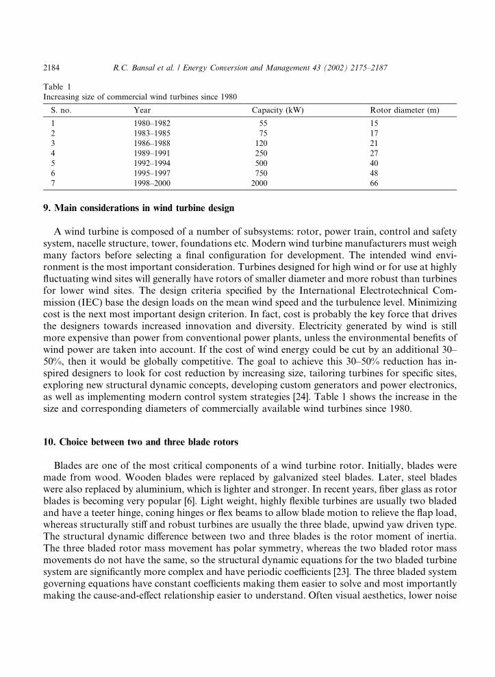
A wind turbine is composed of a number of subsystems: rotor, power train, control and safetysystem, nacelle structure, tower, foundations etc. Modern wind turbine manufacturers must weighmany factors before selecting a final configuration for development. The intended wind envi-ronment is the most important consideration. Turbines designed for high wind or for use at highlyfluctuating wind sites will generally have rotors of smaller diameter and more robust than turbinesfor lower wind sites. The design criteria specified by the International Electrotechnical Com-mission (IEC) base the design loads on the mean wind speed and the turbulence level. Minimizingcost is the next most important design criterion. In fact, cost is probably the key force that drivesthe designers towards increased innovation and diversity. Electricity generated by wind is stillmore expensive than power from conventional power plants, unless the environmental benefits ofwind power are taken into account. If the cost of wind energy could be cut by an additional 30–50%, then it would be globally competitive. The goal to achieve this 30–50% reduction has in-spired designers to look for cost reduction by increasing size, tailoring turbines for specific sites,exploring new structural dynamic concepts, developing custom generators and power electronics,as well as implementing modern control system strategies [24]. Table 1 shows the increase in thesize and corresponding diameters of commercially available wind turbines since 1980.
10. Choice between two and three blade rotors
Blades are one of the most critical components of a wind turbine rotor. Initially, blades weremade from wood. Wooden blades were replaced by galvanized steel blades. Later, steel bladeswere also replaced by aluminium, which is lighter and stronger. In recent years, fiber glass as rotorblades is becoming very popular [6]. Light weight, highly flexible turbines are usually two bladedand have a teeter hinge, coning hinges or flex beams to allow blade motion to relieve the flap load,whereas structurally stiff and robust turbines are usually the three blade, upwind yaw driven type.The structural dynamic difference between two and three blades is the rotor moment of inertia.The three bladed rotor mass movement has polar symmetry, whereas the two bladed rotor massmovements do not have the same, so the structural dynamic equations for the two bladed turbinesystem are significantly more complex and have periodic coefficients [23]. The three bladed systemgoverning equations have constant coefficients making them easier to solve and most importantlymaking the cause-and-effect relationship easier to understand. Often visual aesthetics, lower noise
Table 1
Increasing size of commercial wind turbines since 1980
S. no. Year Capacity (kW) Rotor diameter (m)
1 1980–1982 55 15
2 1983–1985 75 17
3 1986–1988 120 21
4 1989–1991 250 27
5 1992–1994 500 40
6 1995–1997 750 48
7 1998–2000 2000 66
2184 R.C. Bansal et al. / Energy Conversion and Management 43 (2002) 2175–2187
and polar symmetry are reasons for using three blade designs. However, the greater weight andhigher cost of the three blades provide a compelling reason for designers to explore the possi-bilities of two blade rotors more thoroughly.
11. Weight and size considerations
Towers are as integral to the performance of the wind system as the wind turbine itself. Thetower must be strong enough to withstand the thrust on the wind turbine and the thrust on thetower. The tower must also support the weight of the wind turbine. Tall towers are preferred asthey minimize the turbulence induced. Tall towers allow more flexibility in siting. The most im-portant factor is the ability of a tower to withstand the forces acting on it in high winds. Towersare rated by the thrust load they can endure without buckling. The thrust on the tower at highspeeds depends on the rotor diameter of the wind turbine and its mode of operation under suchconditions.As the turbine weight increases, the initial cost also increases. However initial turbine cost alone
does not determine the cost per kilowatt hour of electrical output. The cost of operation andmaintenance (O&M) and the cost of major overhauls and repairs must be included. To be costeffective, a turbine must have high availability and low O&M costs [23]. This leads to differentdesign perspectives. Designers of heavier weight and robust turbines argue that such designs havehigh availability and low maintenance and reducing weight excessively will increase O&M costs.Lightweight turbines, while reducing initial cost and weight must have low O&M costs. Thistechnical challenge requires a thorough understanding of the dynamic behavior of the lightweightturbines and how to control the structure responses. The variation in tower top weight is 20–30kg/m2 for an increase in rotor diameter from 30 to 60 m [13]. The weight of the tower increaseswith the number of blades. Pitch controlled turbines are somewhat lighter than stall regulatedturbines with increase in the size, the cost increases, but with the increase in tower height, theenergy capture is more, which negates such high cost.
12. Environmental aspects
12.1. Audible noise
The wind turbine is generally quiet. It poses no objectionable noise disturbance in the sur-rounding area. The wind turbine manufacturers generally supply the noise level data in dB versusthe distance from the tower. A typical 600 kW wind turbine may produce 55 dB noise at 50 mdistance from the turbine and 40 dB at a 250 m distance [10]. This noise is, however, a steady statenoise. The wind turbine makes loud noise while yawing under changing wind direction. Localnoise ordinances must be satisfied before installing wind turbines.
12.2. Electromagnetic interference
Any stationary or moving structure in the proximity of a radio or TV station interferes with thesignals. The wind turbine towers can cause objectionable electromagnetic interference (EMI) onthe performance of the nearby transmitters or receivers [10].
R.C. Bansal et al. / Energy Conversion and Management 43 (2002) 2175–2187 2185
In other aspects, the visual impact of the wind farm can be of concern to some one. Thebreeding and feeding patterns of birds may be disturbed [6]. They may even be injured and evenkilled if they collide with the blades.
13. Conclusions
The design of wind energy conversion systems is a very complex task and requires interdis-ciplinary skills, e.g. civil, mechanical, electrical and electronics, geography, aerospace, environ-mental etc. An attempt has been made to discuss the important design aspects of WECs. In thispaper, design aspects, such as factors affecting wind power, siting requirements for WECs, prob-lems related with grid connections, classification of wind electric generation schemes, criteria forselection of equipment for WECs, choice of generators, three basic design philosophies, mainconsiderations in wind turbine design, choice between two and three blade rotors, weight and sizeconsiderations and environmentally related aspects with WECs, have been critically discussed.
References
[1] Culp AW. Principles of Energy Conversion. 2nd ed. New York: Mc-Graw Hill. 1991; p. 402–9.
[2] Power line, Power line Research, vol. 4(6), D-4/5, Second Floor, Vasant Vihar, New Delhi, March 2000. p. 49–53.
[3] Johnson GL. Economic design of wind electric generators. IEEE Trans Power Apparatus Syst 1978;PAS-
97(2):554–62.
[4] Jayadev TS. Windmills stage a comeback. IEEE Spectrum 1997:45–9.
[5] Fung KT, Scheffler RL, Stolpe J. Wind energy—a utility perspective. IEEE Trans Power Apparatus Syst
1981;PAS-100(3):1176–82.
[6] Twidel JW, Weir AD. Renewable energy sources. London: English Language Book Society (ELBS), E&FN Spon;
1986.
[7] Gipe P. Wind power. Post Mills, Vermount, USA: Chelsea Green Publishing Company; 1995.
[8] Gupta AK. Wind power development in India. J Inst Engrs (India) Electr Engng 1998;79:35–7.
[9] Naidu BSK. Wind Power Development in India under International Assistance. 1st Indian Wind Power
Convention, Wind Power India’96 at Ooty, Tamilnadu, November 21–22, 1996. p. 107–21.
[10] Patel MR. Wind and solar power systems. Boca Raton, Florida, USA: CRC Press LLC; 1999.
[11] Bellarmine GT, Urquhart J. Wind energy for the 1990s and beyond. Energy Convers Mgmt 1996;37(12):1741–52.
[12] Saad-Saund Z, Lisboa ML, Ekanayka JB, Jenkins N, Strbac G. Application of statcoms to wind farms. IEE Proc
Gener Transm Distrib 1998;145(5):511–6.
[13] Rai GD. Non Conventional Energy Sources. 4th ed. New Delhi, India: Khanna Publishers; 2000.
[14] Singh B. Induction generator—a prospective. Electric Machines Power Syst 1995;23:163–77.
[15] Khan PKS, Chatterjee JK. Three-phase induction generators: a discussion on performance. Electric Machines
Power Syst 1998;27:813–32.
[16] Vicatos MS, Teqopoulos JA. Steady state analysis of a doubly-fed induction generator under synchronous
operation. IEEE Trans Energy Convers 1989;4(3):495–501.
[17] Shi A-J, Thorp J, Thomas R. An AC/DC/AC interface control strategy to improve wind energy economics. IEEE
Trans Power Apparatus Syst 1985;PAS-104(12):3428–33.
[18] Elder JM, Boys JT, Woodward JL. The process of self excitation in induction generators. IEE Proc B
1983;131(2):103–8.
[19] Nagrath IJ, Kothari DP. Electrical machines. 2nd ed. New Delhi: Mc-Graw Hill; 1997.
[20] Murthy SS, Malik OP, Tandon AK. Analysis of self excited induction generator. IEE Proc C 1982;129(6):260–5.
2186 R.C. Bansal et al. / Energy Conversion and Management 43 (2002) 2175–2187
[21] Tandon AK, Murthy SS, Berg GJ. Steady state analysis of capacitors excited induction generators. IEEE Trans
Power Apparatus Syst 1984;PAS-103(3):612–8.
[22] Hunter R, Elliot G. Wind diesel systems, a guide to the technology and its implementation. Cambridge, MA:
Cambridge University Press; 1994.
[23] Thresher RW, Dodge DM. Trends in the evolution of wind turbine generator configurations and systems. Int J
Wind Energy 1998;1:70–85.
[24] Quarton DC. The evolution of wind turbine design analysis—a twenty years progress review. Int J Wind Energy
1998;1:5–24.
R.C. Bansal et al. / Energy Conversion and Management 43 (2002) 2175–2187 2187