on protocol-independent data redundancy elimination
TRANSCRIPT
IEEE COMMUNICATIONS SURVEYS & TUTORIALS, VOL. 16, NO. 1, FIRST QUARTER 2014 455
On Protocol-Independent Data RedundancyElimination
Yan Zhang, Student Member, IEEE, and Nirwan Ansari, Fellow, IEEE
Abstract—Data redundancy elimination (DRE), also known asdata de-duplication, reduces the amount of data to be trans-ferred or stored by identifying and eliminating both intra-objectand inter-object duplicated data elements with a reference orpointer to the unique data copy. Large scale trace-driven studieshave showed that packet-level DRE techniques can achieve 15-60% bandwidth savings when deployed at access links of theservice providers, up to almost 50% bandwidth savings in Wi-Finetworks and as much as 60% mobile data volume reductionin cellular networks. In this paper, we survey the state-of-the-art protocol-independent redundancy elimination techniques.We overview the system architecture and main processing ofprotocol-independent DRE techniques, followed by discussion onmajor mechanisms activated in protocol-independent DRE, in-cluding the fingerprinting mechanism, cache management mech-anism, chunk matching mechanism, and decoding error recoverymechanism. We also present several redundancy eliminationsystems deployed in wireline, wireless and cellular networks,respectively. Several other techniques to enhance the DRE per-formance are further discussed, such as DRE bypass techniques,non-uniform sampling, and chunk overlap.
Index Terms—Data redundancy elimination (DRE), protocol-independent DRE, data de-duplication, content delivery acceler-ation, wide area network (WAN) optimization.
I. INTRODUCTION
A SIGNIFICANT amount of redundant traffic has longbeen observed over the communication networks [1–4].
The observed redundancy in Internet traffic is typically in therange of 15-60%. Internet traffic redundancy stems naturallyfrom the distribution of highly-popular Internet contents andthe large number of Internet users. Some of the contents onthe Internet are highly popular objects which are requested andtransferred repeatedly across the network for a large numberof users. Moreover, this redundancy arises from common end-user activities, e.g., repeatedly accessing, retrieving, distribut-ing the same or similar contents over the Internet several timesa day. As a result, a large amount of the same or similarcontents have been transferred repeatedly across the Internetin both client-server and peer-to-peer applications.
Redundant traffic wastes network resources, worsens thecommunication performance by saturating the network band-width, and increases the economic costs if usage-based chargesare used. With the rapid growth of the Internet traffic [5],redundancy elimination has attracted much attention in recentyears from the academia [1–4, 6–15] and industries, such
Manuscript received September 12, 2012; revised February 2, 2013 andApril 30, 2013.
Y. Zhang and N. Ansari are with the Advanced Networking Lab., De-partment of Electrical and Computer Engineering, New Jersey Instituteof Technology, Newark, NJ, 07102 USA (e-mail:[email protected] and [email protected]).
Digital Object Identifier 10.1109/SURV.2013.052213.00186
as Cisco [16], Juniper [17], BlueCoat [18], and Riverbed[19]. A number of existing diverse systems and solutionshave been explored to improve the network efficiency andcommunication performance by eliminating the redundanttransfers in the network. It has been widely agreed thatredundancy elimination offers significant benefits in practice.The overall benefit of data redundancy elimination is betternetwork delivery performance in terms of higher networkthroughput, lower response time and higher effective networkutilization.
A majority of traditional redundant elimination solutionsoperate at the application layer and object level, such asdata compression [20] (e.g., GZip) which can remove theredundant content within one object efficiently, and objectcaching, including web proxy caches [21] and peer-to-peermedia caches [22], which can be deployed to serve thefrequent and repeated requests from the cache instead of theoriginal source. However, object-compression and application-layer object-level caching cannot eliminate all the redundantcontents alone [1]. Wolman et al. [23] estimated that at most45% of the traffic transmitted from the web servers to theclients to serve the web content requests can be eliminatedby using proxy caches based on the Squid [24] cacheabilityrules. Moreover, neither object compression nor object-levelcaching work well for contents that have been changed inonly minor ways. Delta encoding [25–27], which is based onthe differences between versions of a single document, canhelp in this case by only transferring the changes. However,this also limits the application of delta encoding becauseboth the sender and receiver have to share the same basecontent, which is not applicable for general Internet traffic.As a software application and network protocol, rsync [28]provides fast files and/or directories synchronization from onelocation to another, and reduces the bandwidth consumedduring file transfers. By default, rsync determines the files tobe synchronized by checking the modification time and sizeof each file, and determines the chunks to be sent by usingdelta encoding. Thus, rsync lowers the bandwidth consumptionduring file transfers since only the new files and those partsof the files which have changed will be transferred. Similarto delta encoding, rsync is also not applicable for generalredundant Internet traffic elimination.
In order to eliminate the redundancy within individualobjects, such as packets, files, or web pages, as well asacross objects, protocol-independent redundancy eliminationtechniques operating on individual packets [1, 3, 9–15] havebeen explored and investigated recently. Data redundancyelimination (DRE) [8, 29], also known as data de-duplication,is a data reduction technique and a derivative of data com-
1553-877X/14/$31.00 c© 2014 IEEE
456 IEEE COMMUNICATIONS SURVEYS & TUTORIALS, VOL. 16, NO. 1, FIRST QUARTER 2014
Packet CacheServer
Packet Cache Client
Original Packet
Shrinked Packet Shrinked Packet
Reconstructed PacketRouter Router
Fingerprint Table Packet Storage Cache
Incoming original packet
PacketPayload
FP_A & Pointer
FP_B & Pointer
Chunk A
Chunk A
Chunk B
Chunk B
FP_B =hash (Chunk B)
Fingerprint Table Packet Storage Cache
Encoded Packet
FP_A & Pointer
FP_B & Pointer
Meta_Data_A
Chunk A
Chunk B
Meta_Data_BFP_A =hash (Chunk A)
Reconstructed Packet
Meta_Data_A Meta_Data_B
Encoded Packet
Chunk A Chunk B
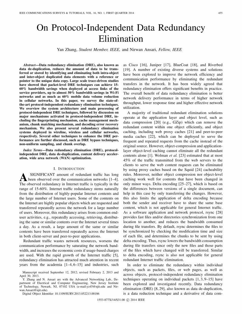
Fig. 1. The classical packet-level data redundancy elimination.
pression. Data compression [20] reduces the file size byeliminating redundant data contained within an object whileDRE can identify and eliminate both intra-object and inter-object duplicated data elements, such as an entire file and adata block, to reduce the amount of data to be transferredor stored. The main idea of protocol-independent packet-levelredundancy elimination is to identify and eliminate redundantchunks across different packets. When multiple instances ofthe same data element are detected, only one single copy ofthe data element is transferred or stored. The redundant dataelement is replaced with a reference or pointer to the uniquedata copy.
Protocol-independent redundancy elimination is becomingincreasingly popular. Pioneered by Spring et al. [1], protocol-independent redundancy elimination techniques have been de-ployed in wide-area, wireless and mobile network acceleratormiddle-boxes [30, 31], and many vendors, e.g., Cisco [16],Juniper [17], BlueCoat [18], and Riverbed [19], offer suchtraffic redundancy elimination middle-boxes to improve thenetwork effective bandwidth. Aggarwal et al. [3] proposedto deploy DRE at the end hosts to maximize the single-linkbandwidth savings, because the amount of contents sent to thedestination host can be minimized even for encrypted traffic.Works reported in [9, 10, 32] further expand the benefits ofdeploying DRE network-wide to eliminate both intra source-destination pair and inter source-destination pairs redundanttraffic. Furthermore, great efforts have been explored forredundancy elimination in wireless and mobile environments[33–36]. In addition, PACK (Predictive ACKs) [37], an end-to-end redundancy elimination scheme, has been designed forcloud computing applications.
Based on several tera-bytes of traffic traces collected atdifferent wireline network locations, a large scale trace-drivenstudy on the efficiency of packet-level protocol-independentDRE [2] showed that protocol-independent DRE can achieveaverage bandwidth savings of 15-60% when deployed ataccess links of the service providers or between routers.Experimental evaluations on various DRE technologies are
presented in [2, 3, 29]. The effects of protocol-independentDRE on redundant traffic elimination in wireless and cellularnetworks have also been explored by several studies [33, 34,36, 38]. Based on real-world Wi-Fi and cellular network traces,up to almost 50% bandwidth savings in Wi-Fi networks [33,38] and as much as 60% mobile data volume reduction incellular networks [34, 36] can be achieved. All of these stud-ies convinced us that protocol-independent DRE techniquesare effective to eliminate redundant traffic over networks.However, it should also be noticed that DRE techniquesfor identifying and eliminating redundant contents are veryexpensive in terms of memory and processing capability. Inthis paper, we provide a survey on the state of the art ofprotocol-independent data redundancy elimination techniques,including its system architecture and main processes, andsome techniques to enhance the DRE performance. We alsodiscuss several DRE systems deployed in wireline, wirelessand cellular networks, respectively, in terms of deploymentarchitectures, redundancy identification methods, and cachemanagement.
The rest of the survey is structured as follows. We detailthe system architecture of protocol-independent DRE and itsmajor processing mechanisms, including fingerprinting, cachemanagement, chunk matching, and decoding error recovery inSection II. Then, we present several redundancy eliminationsystems deployed in wireline, wireless and cellular networksin Sections III and IV. In Section V, we discuss severaltechniques to enhance the DRE performance, such as DREbypass techniques, non-uniform sampling, and chunk overlap.Finally, Section VI concludes the paper. Unless otherwisestated, DRE techniques discussed in the following sectionsare restricted to protocol-independent DRE techniques.
II. COMPONENTS OF PROTOCOL-INDEPENDENT DREIn this section, we provide a detailed overview on the
system architecture and the main processing procedures ofprotocol-independent DRE techniques. We also discuss severalmajor mechanisms activated in protocol-independent DRE,
ZHANG and ANSARI: ON PROTOCOL-INDEPENDENT DATA REDUNDANCY ELIMINATION 457
FingerprintingIndexing &Lookup Storing Data
RepresentativeFingerprints & Positions
Data Packet Compressed Packet
Packet CacheFingerprint Table
DataEncoding
Data DecodingCompressed PacketData Packet
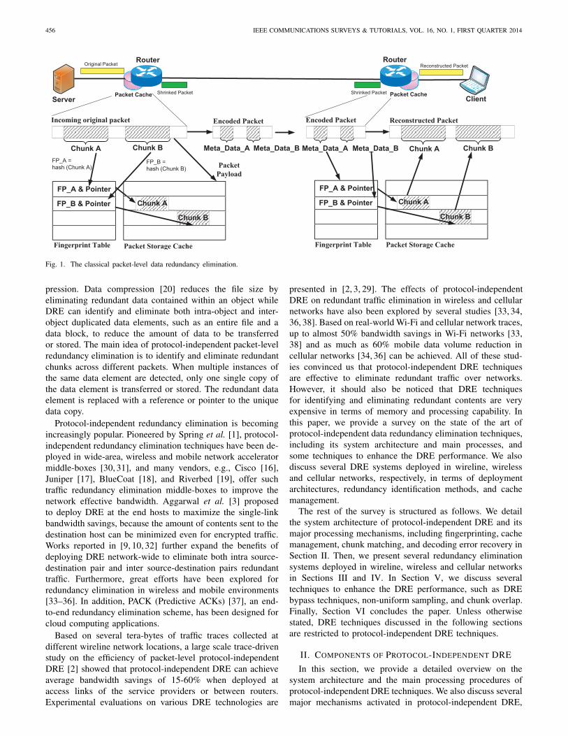
Fig. 2. The main processing blocks of protocol-independent DRE.
including fingerprinting, cache management, chunk matching,and decoding error recovery.
A. Overview of Protocol-Independent DRE
The main idea of protocol-independent DRE is to encodethe outgoing packets by replacing identified redundant datachunks with fixed-size meta-data. At the receiver end router,the packets are reconstructed by replacing the encoded contentfrom the packet cache by using the pointer information carriedin the encoded packets. The packet-level DRE techniquesrely on deploying a fingerprint table and a packet cache ateach end of a network path. In general, the DRE algorithmsassume that the packet caches located at both ends are alwayssynchronized. Thus, the redundant chunks identified againstthe packet-cache at the source-side router can be removedfrom the packets since it can be recovered by the receiver-side router.
A typical protocol-independent packet-level DRE imple-mentation is shown in Fig. 1. For every incoming packet in aparticular direction, the DRE algorithm first computes a setof fingerprints by applying a hash function to each chunkof the packet, which is a sub-string of the packet’s payload.Limited by the size of the fingerprint table, only a subset ofthese fingerprints is selected as its representative fingerprintsin some way which will be discussed in Section II-B. Boththe representative fingerprints and pointers pointing to thelocations of the chunks in the packet cache used to calculate itscorresponding fingerprints are stored in the fingerprint table.Each representative fingerprint is then checked against thefingerprint table to find a matched data chunk in the packetcache. If such a matched chunk in the packet cache is found,the original data chunk in the packet is encoded with a meta-data, which consists of sufficient information to reconstruct theencoded data chunk at the receiver side, such as fingerprintand the description of the matched chunk range, includinga count of redundant bytes before and after the data chunkthat is used to calculate the fingerprint. In practice, the sizeof such meta-data is much smaller than that of the originaldata chunk. In this example, two chunks are identified asredundant data chunks and the packet is encoded by replacingthe original redundant data chunks with the correspondingmeta-data. When the other end router receives the encodedpacket, it will reconstruct the original packet following theinformation carried in the meta-data by using the fingerprinttable and packet cache at the receiver side.
The main processing stages involved in redundancy elim-ination include fingerprinting, indexing and lookup, storingdata, and data encoding and decoding as shown in Fig. 2.Fingerprinting, also called chunk selection, facilitates the iden-tification of redundant chunks within and across the packets.For every incoming packet in a particular direction, it calcu-lates a set of fingerprints for each packet by applying a hashfunction to each chunk of the packet and selects a subset ofthese fingerprints as the representative fingerprints. Each rep-resentative fingerprint is then checked against the fingerprinttable in the processing stage of indexing and lookup. If onefingerprint already exists in the fingerprint table, a redundantchunk is then identified and its corresponding position ofthe matched region in the packet cache is also located byusing its location information stored in the fingerprint table.Hence, the lookup procedure in this stage involves two parts:fingerprint lookup in the fingerprint table and redundant chunklookup in the packet store. If one or multiple redundant chunkshave been identified in an arriving packet, the packet will gothrough an encoding procedure by replacing every identifiedredundant chunk by its corresponding fingerprint description,which consists of the fingerprint as well as the byte rangefor the matched region in the packet cache. Finally, the newpacket is inserted into the packet store and its representativefingerprints are also indexed and stored in the fingerprinttable together with the location information of the chunksused to calculate these representative fingerprints in the packetcache. Data decoding performs the reverse operations of dataencoding and tries to reconstruct the original packet from thecompressed packet by retrieving the chunks from the packetcache by using the information carried in meta-data. The DREdecoder uses the fingerprint value stored in the meta-data tocheck against the fingerprint table. If such a fingerprint valueis found in the fingerprint table, the data chunk will be fetchedfrom the packet cache by using the pointer information storedin the fingerprint table and the count of the redundant bytesbefore and after the chunk used to calculate the fingerprint.Then, the original packet is reconstructed by replacing themeta-data with these fetched data chunks from the packetcache. If such a fingerprint cannot be found in the fingerprinttable at the receiver end router, a decoding error occurs and arecovery process will be activated, which will be discussedin Section II-E. A rather detailed description of the basicoperations of DRE can be found in [39].
The main bottleneck limiting the processing throughputof packet-level DRE is the memory access. Assume that
458 IEEE COMMUNICATIONS SURVEYS & TUTORIALS, VOL. 16, NO. 1, FIRST QUARTER 2014
the memory can be accessed R times per second at themaximum, and F fingerprints are computed for each packetthat has at most k matches. In general, k ≤ F because thenumber of matches can never be more than the number ofcalculated fingerprints. The packet-level DRE encodings canbe applied to at most R/F packets per second because Frandom memory accesses for each packet are required to checkthe matched fingerprints and further processing is required toencode the packet if one match is found, while the decodingoperations can be applied to at least R/k packets per secondbecause at most k matches can be found for each packet.Thus, R/F ≤ R/k, implying that the decoding process ismuch faster than the encoding process. Moreover, supposethat all packets are assumed to be of the same size and thelink capacity is assumed to be P packets per second. If theDRE encoding rate R/F packets per second is larger than thelink capacity P packets per second, the packets can be DREencoded up to P packets per second, meaning that line rateDRE encoding and decoding are possible; otherwise, no morethan R/F packets can be encoded in every second to ensureline-rate operation, and the decoding rate is also limited bythe encoding rate.
As described above, several mechanisms are activated in theimplementation of protocol-independent DRE. We will detailthese mechanisms in the following sub-sections.
B. Fingerprinting
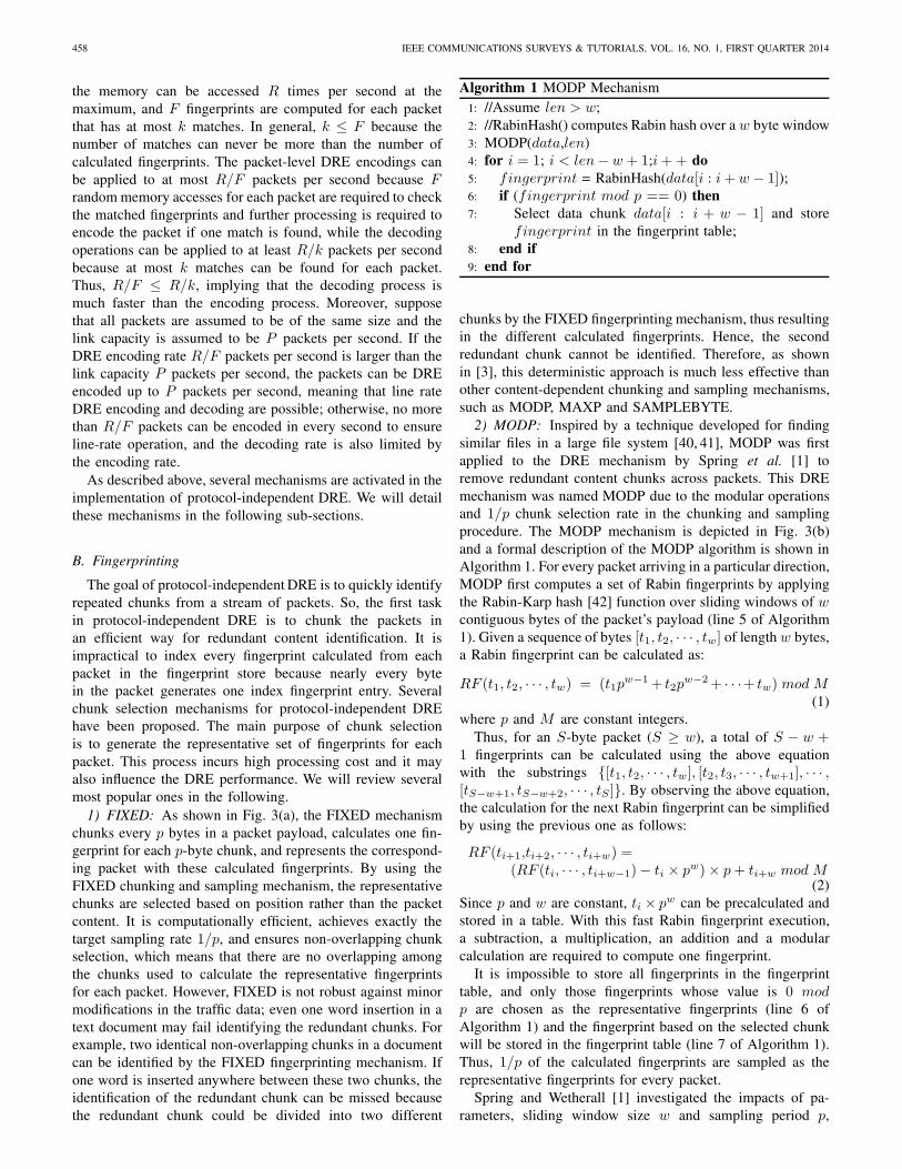
The goal of protocol-independent DRE is to quickly identifyrepeated chunks from a stream of packets. So, the first taskin protocol-independent DRE is to chunk the packets inan efficient way for redundant content identification. It isimpractical to index every fingerprint calculated from eachpacket in the fingerprint store because nearly every bytein the packet generates one index fingerprint entry. Severalchunk selection mechanisms for protocol-independent DREhave been proposed. The main purpose of chunk selectionis to generate the representative set of fingerprints for eachpacket. This process incurs high processing cost and it mayalso influence the DRE performance. We will review severalmost popular ones in the following.
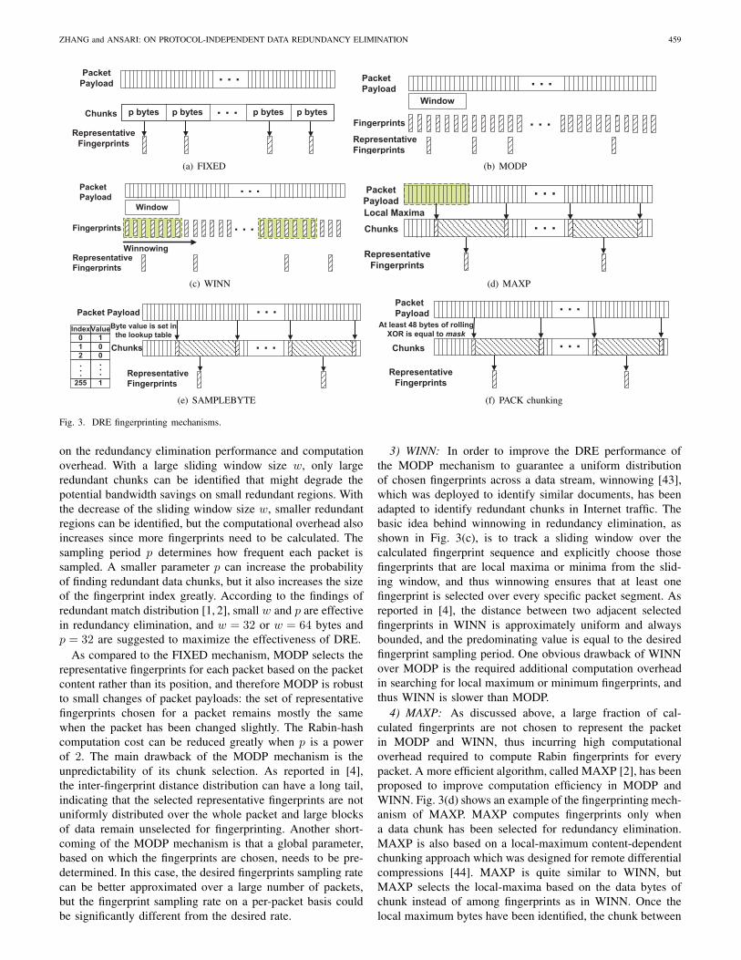
1) FIXED: As shown in Fig. 3(a), the FIXED mechanismchunks every p bytes in a packet payload, calculates one fin-gerprint for each p-byte chunk, and represents the correspond-ing packet with these calculated fingerprints. By using theFIXED chunking and sampling mechanism, the representativechunks are selected based on position rather than the packetcontent. It is computationally efficient, achieves exactly thetarget sampling rate 1/p, and ensures non-overlapping chunkselection, which means that there are no overlapping amongthe chunks used to calculate the representative fingerprintsfor each packet. However, FIXED is not robust against minormodifications in the traffic data; even one word insertion in atext document may fail identifying the redundant chunks. Forexample, two identical non-overlapping chunks in a documentcan be identified by the FIXED fingerprinting mechanism. Ifone word is inserted anywhere between these two chunks, theidentification of the redundant chunk can be missed becausethe redundant chunk could be divided into two different
Algorithm 1 MODP Mechanism1: //Assume len > w;2: //RabinHash() computes Rabin hash over a w byte window3: MODP(data,len)4: for i = 1; i < len− w + 1;i++ do5: fingerprint = RabinHash(data[i : i+ w − 1]);6: if (fingerprint mod p == 0) then7: Select data chunk data[i : i + w − 1] and store
fingerprint in the fingerprint table;8: end if9: end for
chunks by the FIXED fingerprinting mechanism, thus resultingin the different calculated fingerprints. Hence, the secondredundant chunk cannot be identified. Therefore, as shownin [3], this deterministic approach is much less effective thanother content-dependent chunking and sampling mechanisms,such as MODP, MAXP and SAMPLEBYTE.
2) MODP: Inspired by a technique developed for findingsimilar files in a large file system [40, 41], MODP was firstapplied to the DRE mechanism by Spring et al. [1] toremove redundant content chunks across packets. This DREmechanism was named MODP due to the modular operationsand 1/p chunk selection rate in the chunking and samplingprocedure. The MODP mechanism is depicted in Fig. 3(b)and a formal description of the MODP algorithm is shown inAlgorithm 1. For every packet arriving in a particular direction,MODP first computes a set of Rabin fingerprints by applyingthe Rabin-Karp hash [42] function over sliding windows of wcontiguous bytes of the packet’s payload (line 5 of Algorithm1). Given a sequence of bytes [t1, t2, · · · , tw] of length w bytes,a Rabin fingerprint can be calculated as:
RF (t1, t2, · · · , tw) = (t1pw−1+ t2p
w−2+ · · ·+ tw) mod M(1)
where p and M are constant integers.Thus, for an S-byte packet (S ≥ w), a total of S − w +
1 fingerprints can be calculated using the above equationwith the substrings {[t1, t2, · · · , tw], [t2, t3, · · · , tw+1], · · · ,[tS−w+1, tS−w+2, · · · , tS ]}. By observing the above equation,the calculation for the next Rabin fingerprint can be simplifiedby using the previous one as follows:
RF (ti+1,ti+2, · · · , ti+w) =(RF (ti, · · · , ti+w−1)− ti × pw)× p+ ti+w mod M
(2)Since p and w are constant, ti × pw can be precalculated andstored in a table. With this fast Rabin fingerprint execution,a subtraction, a multiplication, an addition and a modularcalculation are required to compute one fingerprint.
It is impossible to store all fingerprints in the fingerprinttable, and only those fingerprints whose value is 0 modp are chosen as the representative fingerprints (line 6 ofAlgorithm 1) and the fingerprint based on the selected chunkwill be stored in the fingerprint table (line 7 of Algorithm 1).Thus, 1/p of the calculated fingerprints are sampled as therepresentative fingerprints for every packet.
Spring and Wetherall [1] investigated the impacts of pa-rameters, sliding window size w and sampling period p,
ZHANG and ANSARI: ON PROTOCOL-INDEPENDENT DATA REDUNDANCY ELIMINATION 459
. . .
RepresentativeFingerprints
PacketPayload
Chunks . . . p bytesp bytesp bytesp bytes
(a) FIXED
Window
. . .
. . .
RepresentativeFingerprints
Fingerprints
PacketPayload
(b) MODP
Window
. . .
. . .
RepresentativeFingerprints
Fingerprints
PacketPayload
Winnowing
(c) WINN
. . .
RepresentativeFingerprints
PacketPayload
. . .Local Maxima
Chunks
(d) MAXP
. . .
RepresentativeFingerprints
Packet Payload
. . .Byte value is set inthe lookup table
Chunks
IndexValue0 11 02 0
...
255 1
...
(e) SAMPLEBYTE
. . .
RepresentativeFingerprints
PacketPayload
. . .At least 48 bytes of rollingXOR is equal to mask
Chunks
(f) PACK chunking
Fig. 3. DRE fingerprinting mechanisms.
on the redundancy elimination performance and computationoverhead. With a large sliding window size w, only largeredundant chunks can be identified that might degrade thepotential bandwidth savings on small redundant regions. Withthe decrease of the sliding window size w, smaller redundantregions can be identified, but the computational overhead alsoincreases since more fingerprints need to be calculated. Thesampling period p determines how frequent each packet issampled. A smaller parameter p can increase the probabilityof finding redundant data chunks, but it also increases the sizeof the fingerprint index greatly. According to the findings ofredundant match distribution [1, 2], small w and p are effectivein redundancy elimination, and w = 32 or w = 64 bytes andp = 32 are suggested to maximize the effectiveness of DRE.
As compared to the FIXED mechanism, MODP selects therepresentative fingerprints for each packet based on the packetcontent rather than its position, and therefore MODP is robustto small changes of packet payloads: the set of representativefingerprints chosen for a packet remains mostly the samewhen the packet has been changed slightly. The Rabin-hashcomputation cost can be reduced greatly when p is a powerof 2. The main drawback of the MODP mechanism is theunpredictability of its chunk selection. As reported in [4],the inter-fingerprint distance distribution can have a long tail,indicating that the selected representative fingerprints are notuniformly distributed over the whole packet and large blocksof data remain unselected for fingerprinting. Another short-coming of the MODP mechanism is that a global parameter,based on which the fingerprints are chosen, needs to be pre-determined. In this case, the desired fingerprints sampling ratecan be better approximated over a large number of packets,but the fingerprint sampling rate on a per-packet basis couldbe significantly different from the desired rate.
3) WINN: In order to improve the DRE performance ofthe MODP mechanism to guarantee a uniform distributionof chosen fingerprints across a data stream, winnowing [43],which was deployed to identify similar documents, has beenadapted to identify redundant chunks in Internet traffic. Thebasic idea behind winnowing in redundancy elimination, asshown in Fig. 3(c), is to track a sliding window over thecalculated fingerprint sequence and explicitly choose thosefingerprints that are local maxima or minima from the slid-ing window, and thus winnowing ensures that at least onefingerprint is selected over every specific packet segment. Asreported in [4], the distance between two adjacent selectedfingerprints in WINN is approximately uniform and alwaysbounded, and the predominating value is equal to the desiredfingerprint sampling period. One obvious drawback of WINNover MODP is the required additional computation overheadin searching for local maximum or minimum fingerprints, andthus WINN is slower than MODP.
4) MAXP: As discussed above, a large fraction of cal-culated fingerprints are not chosen to represent the packetin MODP and WINN, thus incurring high computationaloverhead required to compute Rabin fingerprints for everypacket. A more efficient algorithm, called MAXP [2], has beenproposed to improve computation efficiency in MODP andWINN. Fig. 3(d) shows an example of the fingerprinting mech-anism of MAXP. MAXP computes fingerprints only whena data chunk has been selected for redundancy elimination.MAXP is also based on a local-maximum content-dependentchunking approach which was designed for remote differentialcompressions [44]. MAXP is quite similar to WINN, butMAXP selects the local-maxima based on the data bytes ofchunk instead of among fingerprints as in WINN. Once thelocal maximum bytes have been identified, the chunk between
460 IEEE COMMUNICATIONS SURVEYS & TUTORIALS, VOL. 16, NO. 1, FIRST QUARTER 2014
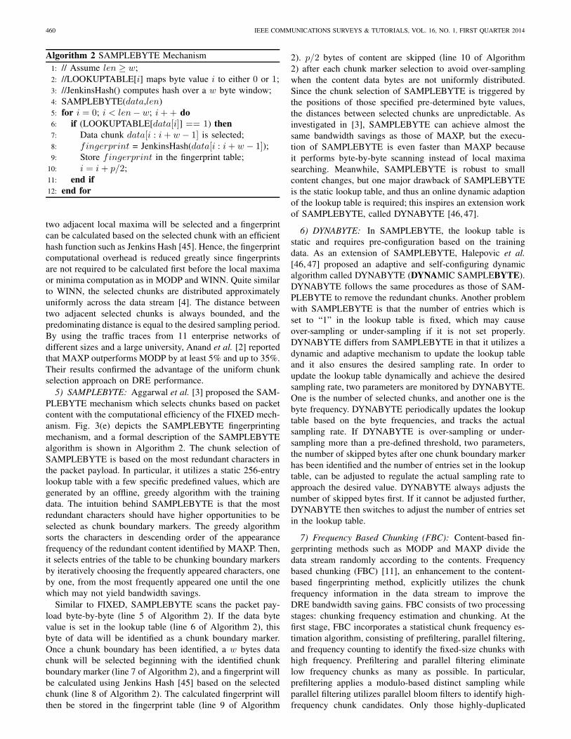
Algorithm 2 SAMPLEBYTE Mechanism1: // Assume len ≥ w;2: //LOOKUPTABLE[i] maps byte value i to either 0 or 1;3: //JenkinsHash() computes hash over a w byte window;4: SAMPLEBYTE(data,len)5: for i = 0; i < len− w; i++ do6: if (LOOKUPTABLE[data[i]] == 1) then7: Data chunk data[i : i+ w − 1] is selected;8: fingerprint = JenkinsHash(data[i : i+ w − 1]);9: Store fingerprint in the fingerprint table;
10: i = i + p/2;11: end if12: end for
two adjacent local maxima will be selected and a fingerprintcan be calculated based on the selected chunk with an efficienthash function such as Jenkins Hash [45]. Hence, the fingerprintcomputational overhead is reduced greatly since fingerprintsare not required to be calculated first before the local maximaor minima computation as in MODP and WINN. Quite similarto WINN, the selected chunks are distributed approximatelyuniformly across the data stream [4]. The distance betweentwo adjacent selected chunks is always bounded, and thepredominating distance is equal to the desired sampling period.By using the traffic traces from 11 enterprise networks ofdifferent sizes and a large university, Anand et al. [2] reportedthat MAXP outperforms MODP by at least 5% and up to 35%.Their results confirmed the advantage of the uniform chunkselection approach on DRE performance.
5) SAMPLEBYTE: Aggarwal et al. [3] proposed the SAM-PLEBYTE mechanism which selects chunks based on packetcontent with the computational efficiency of the FIXED mech-anism. Fig. 3(e) depicts the SAMPLEBYTE fingerprintingmechanism, and a formal description of the SAMPLEBYTEalgorithm is shown in Algorithm 2. The chunk selection ofSAMPLEBYTE is based on the most redundant characters inthe packet payload. In particular, it utilizes a static 256-entrylookup table with a few specific predefined values, which aregenerated by an offline, greedy algorithm with the trainingdata. The intuition behind SAMPLEBYTE is that the mostredundant characters should have higher opportunities to beselected as chunk boundary markers. The greedy algorithmsorts the characters in descending order of the appearancefrequency of the redundant content identified by MAXP. Then,it selects entries of the table to be chunking boundary markersby iteratively choosing the frequently appeared characters, oneby one, from the most frequently appeared one until the onewhich may not yield bandwidth savings.
Similar to FIXED, SAMPLEBYTE scans the packet pay-load byte-by-byte (line 5 of Algorithm 2). If the data bytevalue is set in the lookup table (line 6 of Algorithm 2), thisbyte of data will be identified as a chunk boundary marker.Once a chunk boundary has been identified, a w bytes datachunk will be selected beginning with the identified chunkboundary marker (line 7 of Algorithm 2), and a fingerprint willbe calculated using Jenkins Hash [45] based on the selectedchunk (line 8 of Algorithm 2). The calculated fingerprint willthen be stored in the fingerprint table (line 9 of Algorithm
2). p/2 bytes of content are skipped (line 10 of Algorithm2) after each chunk marker selection to avoid over-samplingwhen the content data bytes are not uniformly distributed.Since the chunk selection of SAMPLEBYTE is triggered bythe positions of those specified pre-determined byte values,the distances between selected chunks are unpredictable. Asinvestigated in [3], SAMPLEBYTE can achieve almost thesame bandwidth savings as those of MAXP, but the execu-tion of SAMPLEBYTE is even faster than MAXP becauseit performs byte-by-byte scanning instead of local maximasearching. Meanwhile, SAMPLEBYTE is robust to smallcontent changes, but one major drawback of SAMPLEBYTEis the static lookup table, and thus an online dynamic adaptionof the lookup table is required; this inspires an extension workof SAMPLEBYTE, called DYNABYTE [46, 47].
6) DYNABYTE: In SAMPLEBYTE, the lookup table isstatic and requires pre-configuration based on the trainingdata. As an extension of SAMPLEBYTE, Halepovic et al.[46, 47] proposed an adaptive and self-configuring dynamicalgorithm called DYNABYTE (DYNAMIC SAMPLEBYTE).DYNABYTE follows the same procedures as those of SAM-PLEBYTE to remove the redundant chunks. Another problemwith SAMPLEBYTE is that the number of entries which isset to “1” in the lookup table is fixed, which may causeover-sampling or under-sampling if it is not set properly.DYNABYTE differs from SAMPLEBYTE in that it utilizes adynamic and adaptive mechanism to update the lookup tableand it also ensures the desired sampling rate. In order toupdate the lookup table dynamically and achieve the desiredsampling rate, two parameters are monitored by DYNABYTE.One is the number of selected chunks, and another one is thebyte frequency. DYNABYTE periodically updates the lookuptable based on the byte frequencies, and tracks the actualsampling rate. If DYNABYTE is over-sampling or under-sampling more than a pre-defined threshold, two parameters,the number of skipped bytes after one chunk boundary markerhas been identified and the number of entries set in the lookuptable, can be adjusted to regulate the actual sampling rate toapproach the desired value. DYNABYTE always adjusts thenumber of skipped bytes first. If it cannot be adjusted further,DYNABYTE then switches to adjust the number of entries setin the lookup table.
7) Frequency Based Chunking (FBC): Content-based fin-gerprinting methods such as MODP and MAXP divide thedata stream randomly according to the contents. Frequencybased chunking (FBC) [11], an enhancement to the content-based fingerprinting method, explicitly utilizes the chunkfrequency information in the data stream to improve theDRE bandwidth saving gains. FBC consists of two processingstages: chunking frequency estimation and chunking. At thefirst stage, FBC incorporates a statistical chunk frequency es-timation algorithm, consisting of prefiltering, parallel filtering,and frequency counting to identify the fixed-size chunks withhigh frequency. Prefiltering and parallel filtering eliminatelow frequency chunks as many as possible. In particular,prefiltering applies a modulo-based distinct sampling whileparallel filtering utilizes parallel bloom filters to identify high-frequency chunk candidates. Only those highly-duplicated
ZHANG and ANSARI: ON PROTOCOL-INDEPENDENT DATA REDUNDANCY ELIMINATION 461
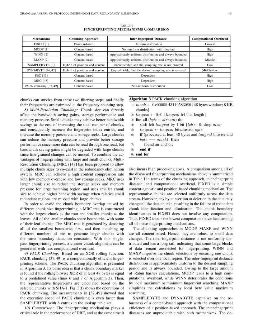
TABLE IFINGERPRINTING MECHANISMS COMPARISON
Mechanisms Chunking Approach Inter-fingerprint Distance Computational OverheadFIXED [3] Position-based Uniform distribution Lowest
MODP [1] Content-based Non-uniform distribution with long-tail High
WINN [2] Content-based Approximately uniform distribution and always bounded High
MAXP [2] Content-based Approximately uniform distribution and always bounded Middle
SAMPLEBYTE [3] Hybrid of position and content Unpredictable and the sampling rate is not ensured Low
DYNABYTE [46, 47] Hybrid of position and content Unpredictable, but the desired sampling rate is ensured Middle-low
FBC [11] Content-based Dependent High
MRC [48] Content-based Dependent High
PACK chunking [37, 49] Content-based Non-uniform distribution Low
chunks can survive from these two filtering steps, and finallytheir frequencies are estimated at the frequency counting step.
8) Multi-Resolution Chunking: Chunk size can directlyaffect the bandwidth saving gains, storage performance andmemory pressure. Small chunks may achieve better bandwidthsavings at the cost of increasing the total number of chunks,and consequently increase the fingerprint index entries, andincrease the memory pressure and storage seeks. Large chunkscan reduce the memory pressure and provide better storageperformance since more data can be read through one read, butbandwidth saving gains might be degraded with large chunkssince fine-grained changes can be missed. To combine the ad-vantages of fingerprinting with large and small chunks, Multi-Resolution Chunking (MRC) [48] has been proposed to allowmultiple chunk sizes to co-exist in the redundancy eliminationsystem. MRC can achieve a high content compression ratewith low memory overhead and low storage seeks. MRC useslarger chunk size to reduce the storage seeks and memorypressure for large matching region, and uses smaller chunksize to achieve higher bandwidth savings when relative smallredundant regions are missed with large chunks.
In order to avoid the chunk boundary overlap caused bydifferent chunk size fingerprinting, a MRC tree is constructedwith the largest chunk as the root and smaller chunks as theleaves. All of the smaller chunks share boundaries with someof their leaf chunks. The MRC tree is generated by detectingall of the smallest boundaries first, and then matching updifferent numbers of bits to generate larger chunks withthe same boundary detection constraint. With this single-pass fingerprinting process, a cleaner chunk alignment can begenerated with less computational overhead.
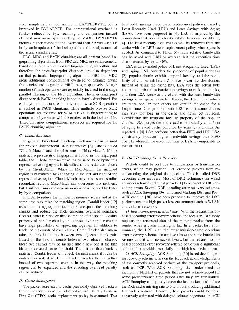
9) PACK Chunking: Based on an XOR rolling function,PACK chunking [37, 49] is a computationally efficient finger-printing scheme. The PACK chunking algorithm is presentedin Algorithm 3. Its basic idea is that a chunk boundary markeris found if the rolling bitwise XOR of at least 48 bytes is equalto a predefined value (lines 6 and 7 of Algorithm 3). Then,the representative fingerprints are calculated based on theselected chunks with SHA-1. Fig. 3(f) shows the operations ofPACK chunking. The measurements in [37, 49] showed thatthe execution speed of PACK chunking is even faster thanSAMPLEBYTE with 8 entries in the lookup table set.
10) Comparison: The fingerprinting mechanism plays acritical role in the performance of DRE, and at the same time it
Algorithm 3 PACK chunking algorithm1: mask ← 0x00008A3110583080 {48 bytes window; 8 KB
chunks}2: longval← 0x0 {longval 64 bits length}3: for all (byte ∈ stream) do4: shift left longval by 1 bit {lsb← 0; drop msb}5: longval← longval bitwise-xor byte6: if (processed at least 48 bytes and longval bitwise-and
byte == mask) then7: found an anchor;8: end if9: end for
also incurs high processing costs. A comparison among all ofthe discussed fingerprinting mechanisms above is summarizedin Table I in terms of the chunking approach, inter-fingerprintdistance, and computational overhead. FIXED is a simplecontent-agnostic and position-based chunking mechanism. Therepresentative chunks are selected uniformly across the datastream. However, any byte insertion or deletion in the data maychange all the data chunks, resulting in the failure of redundantchunk identification and elimination. The chunk boundaryidentification in FIXED does not involve any computation.Thus, FIXED incurs the lowest computational overhead amongall of these fingerprinting mechanisms.
The chunking approaches in MODP, MAXP and WINNare all content-based. Hence, they are robust to small datachanges. The inter-fingerprint distance is not uniformly dis-tributed and has a long tail, indicating that some large blocksof data remain unselected for fingerprinting. WINN andMAXP improve the chunk selections by ensuring one chunkis selected over one local region. The inter-fingerprint distancedistribution is approximately uniform to the desired samplingperiod and is always bounded. Owing to the large amountof Rabin hashes calculations, MODP leads to a high com-putational overhead, while WINN deteriorates the conditionsby local maximum or minimum fingerprint searching. MAXPsimplifies the calculations by local byte value maximumsearching.
SAMPLEBYTE and DYNABYTE capitalize on the ro-bustness of a content-based approach with the computationalefficiency of a position-based approach. The inter-fingerprintdistances are unpredictable with both mechanisms. The de-
462 IEEE COMMUNICATIONS SURVEYS & TUTORIALS, VOL. 16, NO. 1, FIRST QUARTER 2014
sired sample rate is not ensured in SAMPLEBYTE, but isimproved in DYNABYTE. The computational overhead isfurther reduced by byte scanning and comparison insteadof local maximum byte searching in MAXP. DYNABYTEinduces higher computational overhead than SAMPLEBYTEin dynamic updates of the lookup table and the adjustment ofthe actual sampling rate.
FBC, MRC and PACK chunking are all content-based fin-gerprinting algorithms. Both FBC and MRC are enhancementsbased on another content-based fingerprinting algorithm, andtherefore the inter-fingerprint distances are also dependenton that particular fingerprinting algorithm. FBC and MRCincur additional computational overhead to estimate chunkfrequencies and to generate MRC trees, respectively. A largenumber of hash operations are especially incurred in the stageparallel filtering of the FBC algorithm. The inter-fingerprintdistance with PACK chunking is not uniformly distributed. Foreach byte in the data stream, only one bitwise XOR operationis applied in PACK chunking, while multiple bitwise XORoperations are required for SAMPLEBYTE fingerprinting tocompare the byte value with the entries set in the lookup table.Therefore, more computational resources are required for thePACK chunking algorithm.
C. Chunk MatchingIn general, two chunk matching mechanisms can be used
for protocol-independent DRE techniques [3]. One is called“Chunk-Match” and the other one is “Max-Match”. If onematched representative fingerprint is found in the fingerprinttable, the w byte representative region used to compute thisrepresentative fingerprint is identified as the redundant chunkby the Chunk-Match. While in Max-Match, the matchedregion is maximized by expanding to the left and right of therepresentative region. Chunk-Match may miss some similarredundant regions. Max-Match can overcome this problem,but it suffers from excessive memory access induced by byte-by-byte comparison.
In order to reduce the number of memory access and at thesame time maximize the matching region, CombiHeader [12]uses a chunk aggregation technique to expand the matchingchunks and reduce the DRE encoding overhead penalties.CombiHeader is based on the assumption of the spatial localityproperty of popular chunks, i.e., consecutive popular chunkshave high probability of appearing together. In addition totrack the hit counts of each chunk, CombiHeader also main-tains the link-hit counts between two adjacent chunk pair.Based on the link hit counts between two adjacent chunks,these two chunks may be merged into a new one if the linkhit counts exceed some threshold. Then, if the first chunk ismatched, CombiHeader will check the next chunk if it can bematched or not; if so, CombiHeader encodes them togetherinstead of two separated chunks. In this way, the matchingregion can be expanded and the encoding overhead penaltycan be reduced.
D. Cache ManagementThe packet store used to cache previously observed packets
for redundancy elimination is limited in size. Usually, First-In-First-Out (FIFO) cache replacement policy is assumed. Two
bandwidth savings based cache replacement policies, namely,Least Recently Used (LRU) and Least Savings with Aging(LSA), have been proposed in [4]. LRU is inspired by theobservation that popular chunks exhibit temporal locality [2,4]. The least recently used chunks will be removed from thecache with the LRU cache replacement policy when space isneeded. As compared to FIFO, 5% more relative bandwidthcan be saved with LRU on average, but the execution timealso increases by up to 40%.
LSA is an extended policy of Least Frequently Used (LFU)with aging. LSA considers the properties of popular chunks[2]: popular chunks exhibit temporal locality, and the popu-larity of chunks exhibits a Zipf-like power-law distribution.Instead of using the cache hits, LSA uses the actual bytevolume contributed to bandwidth savings to rank the chunks,and then LSA removes the chunk with the least bandwidthsavings when space is needed. Hence, the data chunks whichare more popular than others are kept in the cache for alonger time. One problem with LRU is that some chunksmay stay too long in the cache and never get replaced.Considering the temporal locality property of the popularchunks, LSA purges the entire cache periodically as a formof aging to avoid cache pollution by some data chunks. Asreported in [4], LSA performs better than FIFO and LRU. LSAconsistently produces higher bandwidth savings than FIFOdoes. In addition, the execution time of LSA is comparable tothat of FIFO.
E. DRE Decoding Error Recovery
Packets could be lost due to congestions or transmissionerrors, which may prevent DRE encoded packets from re-constructing the original data packets. This is called DREdecoding error recovery. Most of DRE techniques for wirednetworks retransmit the lost packets [1] to recover the DRE de-coding errors. Several DRE decoding error recovery schemes,such as ACK Snooping [36], Informed Marking [36], and Post-ACK caching [38], have been proposed to improve the DREperformance in a high packet loss environment such as WLANand cellular networks.
1) Retransmission-based scheme: With the retransmission-based decoding error recovery scheme, the receiver just simplyrequests the retransmission of the missing packet from thesender when a cache missing is hit. In a packet-loss envi-ronment, the DRE with the retransmission-based decodingerror recovery scheme can achieve almost the same bandwidthsavings as that with no packet losses, but the retransmission-based decoding error recovery scheme could waste significantadditional bandwidth, especially in a high-loss environment.
2) ACK Snooping: ACK Snooping [36] based decoding er-ror recovery scheme relies on the feedback acknowledgementsof the correctly received packets of the transport protocols,such as TCP. With ACK Snooping, the sender needs tomaintain a blacklist of packets that are not acknowledged forsome predetermined time period after they are transmitted.ACK Snooping can quickly detect the lost packets and reducethe DRE cache missing rate to 0 without introducing additionalfeedback overhead. However, lost packets could be falsenegatively estimated with delayed acknowledgements in ACK
ZHANG and ANSARI: ON PROTOCOL-INDEPENDENT DATA REDUNDANCY ELIMINATION 463
Internet
InternetS-Wanax
S-Wanax
R-Wanax
R-Wanax
R-Wanax
R-Wanax
LAN
Peer Sharing
WAN
Chunk-basedTransfer (MRC)
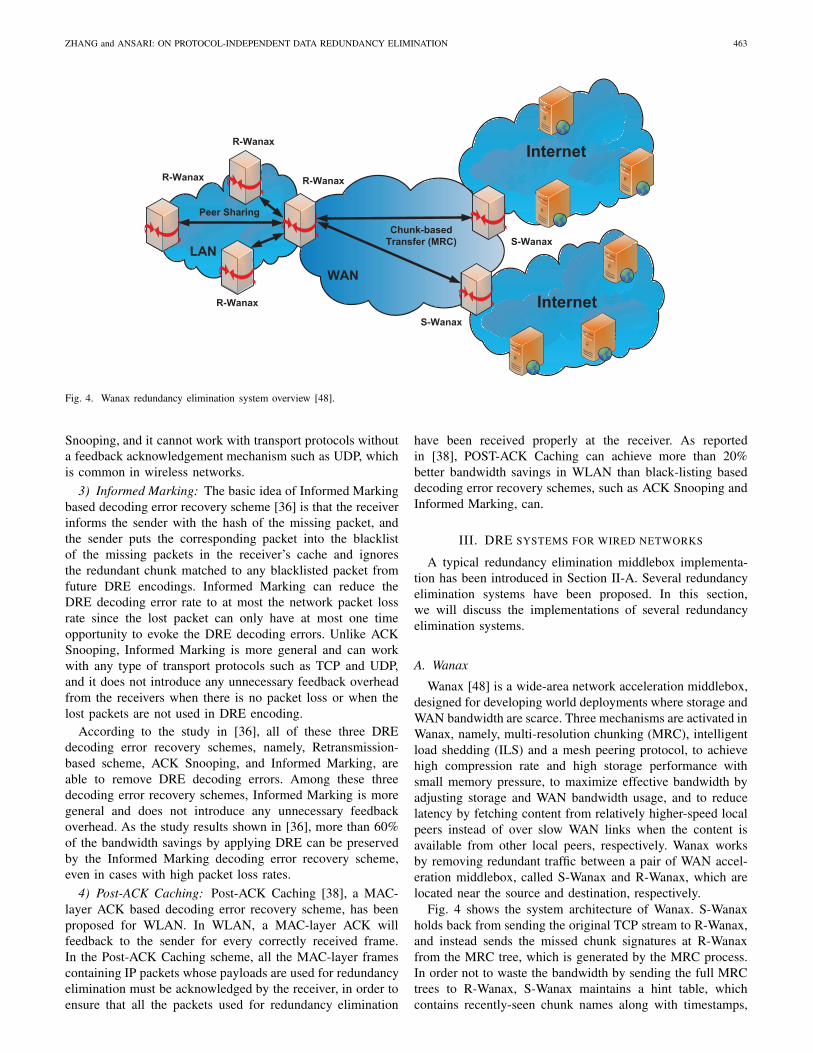
Fig. 4. Wanax redundancy elimination system overview [48].
Snooping, and it cannot work with transport protocols withouta feedback acknowledgement mechanism such as UDP, whichis common in wireless networks.
3) Informed Marking: The basic idea of Informed Markingbased decoding error recovery scheme [36] is that the receiverinforms the sender with the hash of the missing packet, andthe sender puts the corresponding packet into the blacklistof the missing packets in the receiver’s cache and ignoresthe redundant chunk matched to any blacklisted packet fromfuture DRE encodings. Informed Marking can reduce theDRE decoding error rate to at most the network packet lossrate since the lost packet can only have at most one timeopportunity to evoke the DRE decoding errors. Unlike ACKSnooping, Informed Marking is more general and can workwith any type of transport protocols such as TCP and UDP,and it does not introduce any unnecessary feedback overheadfrom the receivers when there is no packet loss or when thelost packets are not used in DRE encoding.
According to the study in [36], all of these three DREdecoding error recovery schemes, namely, Retransmission-based scheme, ACK Snooping, and Informed Marking, areable to remove DRE decoding errors. Among these threedecoding error recovery schemes, Informed Marking is moregeneral and does not introduce any unnecessary feedbackoverhead. As the study results shown in [36], more than 60%of the bandwidth savings by applying DRE can be preservedby the Informed Marking decoding error recovery scheme,even in cases with high packet loss rates.
4) Post-ACK Caching: Post-ACK Caching [38], a MAC-layer ACK based decoding error recovery scheme, has beenproposed for WLAN. In WLAN, a MAC-layer ACK willfeedback to the sender for every correctly received frame.In the Post-ACK Caching scheme, all the MAC-layer framescontaining IP packets whose payloads are used for redundancyelimination must be acknowledged by the receiver, in order toensure that all the packets used for redundancy elimination
have been received properly at the receiver. As reportedin [38], POST-ACK Caching can achieve more than 20%better bandwidth savings in WLAN than black-listing baseddecoding error recovery schemes, such as ACK Snooping andInformed Marking, can.
III. DRE SYSTEMS FOR WIRED NETWORKS
A typical redundancy elimination middlebox implementa-tion has been introduced in Section II-A. Several redundancyelimination systems have been proposed. In this section,we will discuss the implementations of several redundancyelimination systems.
A. Wanax
Wanax [48] is a wide-area network acceleration middlebox,designed for developing world deployments where storage andWAN bandwidth are scarce. Three mechanisms are activated inWanax, namely, multi-resolution chunking (MRC), intelligentload shedding (ILS) and a mesh peering protocol, to achievehigh compression rate and high storage performance withsmall memory pressure, to maximize effective bandwidth byadjusting storage and WAN bandwidth usage, and to reducelatency by fetching content from relatively higher-speed localpeers instead of over slow WAN links when the content isavailable from other local peers, respectively. Wanax worksby removing redundant traffic between a pair of WAN accel-eration middlebox, called S-Wanax and R-Wanax, which arelocated near the source and destination, respectively.
Fig. 4 shows the system architecture of Wanax. S-Wanaxholds back from sending the original TCP stream to R-Wanax,and instead sends the missed chunk signatures at R-Wanaxfrom the MRC tree, which is generated by the MRC process.In order not to waste the bandwidth by sending the full MRCtrees to R-Wanax, S-Wanax maintains a hint table, whichcontains recently-seen chunk names along with timestamps,
464 IEEE COMMUNICATIONS SURVEYS & TUTORIALS, VOL. 16, NO. 1, FIRST QUARTER 2014
Cache
Cache
Cache
Cache
Cache
Cache
Cache
CachingManifests
Routing PolicyRedundancyProfile
Network-wide Optimization
EncodingManifests
Traffic Matrix
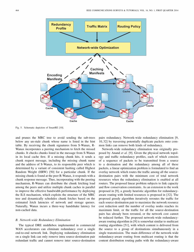
Fig. 5. Schematic depiction of SmartRE [10].
and prunes the MRC tree to avoid sending the sub-treesbelow any un-stale chunk whose name is listed in the hinttable. By receiving the chunk signatures from S-Wanax, R-Wanax incorporates a peering mechanism to fetch the missedchunks. It checks chunks listed in the message from S-Wanaxin its local cache first. If a missing chunk hits, it sends achunk request message, including the missing chunk nameand the address of S-Wanax, to its responsible peer which isdetermined by a variant of consistent hashing called HighestRandom Weight (HRW) [50] for a particular chunk. If themissing chunk is found at the peer R-Wanax, it responds with achunk response message. Thus, incorporating with the peeringmechanism, R-Wanax can distribute the chunk fetching loadamong the peers and utilize multiple chunk caches in parallelto improve the effective bandwidth performance by deployingthe ILS mechanism, which exploits the structure of the MRCtree and dynamically schedules chunk fetches based on theestimated fetch latencies of network and storage queues.Naturally, Wanax incurs a three-way handshake latency fornon-cached data.
B. Network-wide Redundancy Elimination
The typical DRE middlebox implemented in commercialWAN accelerators can eliminate redundancy over a singleend-to-end network link. Deploying redundancy eliminationon a single link can only remove intra source-destination pairredundant traffic and cannot remove inter source-destination
pairs redundancy. Network-wide redundancy elimination [9,10, 32] by traversing potentially duplicate packets onto com-mon links can remove both kinds of redundancy.
Network-wide redundancy elimination was originally pro-posed by Anand et al. [9]. Given the physical network topol-ogy and traffic redundancy profiles, each of which consistsof a sequence of packets to be transmitted from a sourceto a destination and the redundancy among all of thesepackets, a linear optimization problem is formulated to find anoverlay network which routes the traffic among all the source-destination pairs with the minimum cost of total networkresources when the redundancy elimination is enabled at allrouters. The proposed linear problem subjects to link capacityand flow conservation constraints. As an extension to the workproposed in [9], a greedy heuristic algorithm for redundancy-aware routing with limited resources is proposed in [32]. Theproposed greedy algorithm iteratively reroutes the traffic foreach source-destination pair to maximize the network resourcecost reduction until the number of overlay nodes reaches itsmaximum limit, or the traffic for all the source-destinationpairs has already been rerouted, or the network cost cannotbe reduced further. The proposed network-wide redundancy-aware routing algorithm in [9] is somewhat similar to multicastrouting algorithms [51], with which content is delivered fromthe source to a group of destinations simultaneously in asingle transmission. The main difference of the network-wideredundancy-aware routing from multicast routing is that thecontent distribution routing paths with the redundancy-aware
ZHANG and ANSARI: ON PROTOCOL-INDEPENDENT DATA REDUNDANCY ELIMINATION 465
Chunk Store
SYN ACK + PACK permitted
ACK + PRED (data range, hint, signature)
ReceiverSender
SYN ACK + PACK permitted
Data
SYN
Data + PRED ACK
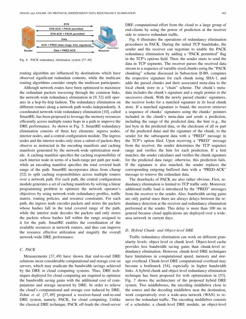
Fig. 6. PACK redundancy elimination system [37, 49].
routing algorithm are influenced by destinations which haveobserved significant redundant contents, while the multicastrouting algorithms consider simply the multicast participants.
Although network routes have been optimized to maximizethe redundant packets traversing through the common links,the network-wide redundancy elimination in [9, 32] still oper-ates in a hop-by-hop fashion. The redundancy elimination ondifferent routers along a network path works independently. Acoordinated network-wide redundancy elimination [10], calledSmartRE, has been proposed to leverage the memory resourcesefficiently across multiple router hops in a path to improve theDRE performance. As shown in Fig. 5, SmartRE redundancyelimination consists of three key elements: ingress nodes,interior nodes, and a central configuration module. The ingressnodes and the interior nodes only store a subset of packets theyobserve as instructed in the encoding manifests and cachingmanifests generated by the network-wide optimization mod-ule. A caching manifest specifies the caching responsibility ofeach interior node in terms of a hash-range per path per node,while an encoding manifest specifies the total covered hashrange of the path. SmartRE incorporates ideas from cSamp[52] to split caching responsibilities across multiple routersover a network path. For each path, the central configurationmodule generates a set of caching manifests by solving a linearprogramming problem to optimize the network operator’sobjectives by using network-wide redundancy profiles, trafficmatrix, routing policies, and resource constraints. For eachpath, the ingress node encodes packets and stores the packetswhose hashes fall in the total covered range of the path,while the interior node decodes the packets and only storesthe packets whose hashes fall within the range assigned toit for the path. SmartRE enables the coordination of theavailable resources at network routers, and thus can improvethe resource effective utilization and magnify the overallnetwork-wide DRE performance.
C. PACK
Measurements [37, 49] have shown that end-to-end DREsolutions incur considerable computational and storage cost onservers, which may eradicate the bandwidth savings achievedby the DRE in cloud computing systems. Thus, DRE tech-niques deployed for cloud computing are required to optimizethe bandwidth saving gains with the additional cost of com-putations and storage incurred by DRE. In order to relievethe cloud’s computational and storage cost induced by DRE,Zohar et al. [37, 49] proposed a receiver-based end-to-endDRE system, namely, PACK, for cloud computing. Unlikethe classical DRE technique, PACK off-loads the cloud-server
DRE computational effort from the cloud to a large group ofend-clients by using the power of prediction at the receiverside to remove redundant traffic.
Fig. 6 illustrates the operations of redundancy eliminationprocedures in PACK. During the initial TCP handshake, thesender and the receiver can negotiate to enable the PACKredundancy elimination by adding a “PACK permitted” flagin the TCP’s options field. Then, the sender starts to send thedata in TCP segments. The receiver parses the received datastream to a sequence of variable sized chunks using the “PACKchunking” scheme discussed in Subsection II-B9, computesthe respective signature for each chunk using SHA-1, andadds the parsed chunks and their associated meta-data to thelocal chunk store in a “chain” scheme. The chunk’s meta-data includes the chunk’s signature and a single pointer to thesuccessive chunk. With the newly parsed chunks’ signatures,the receiver looks for a matched signature in its local chunkstore. If a matched signature is found, the receiver retrievesa sequence of chunks’ signatures using the chunks’ pointersincluded in the chunk’s meta-data and sends a prediction,including the range of the predicted data, the hint (e.g., thelast byte in the predicted data, or the checksum of all or partof the predicted data) and the signature of the chunk, to thesender for the subsequent data with a “PRED” message inthe TCP’s option filed. Upon receiving a “PRED” messagefrom the receiver, the sender determines the TCP sequencerange and verifies the hint for each prediction. If a hintmatches, the sender calculates and verifies the chunk signaturefor the predicted data range; otherwise, this prediction fails.If the signature is also matched, the sender replaces thecorresponding outgoing buffered data with a “PRED-ACK”message to remove the redundant data.
The drawbacks of PACK are also rather obvious. First, re-dundancy elimination is limited to TCP traffic only. Moreover,additional traffic load is introduced by the “PRED” messagesfrom the receiver to the sender. Also, bandwidth saving gainsare only partial since there are always delays between the re-dundancy detection at the receiver and redundancy eliminationperformed at the sender. This delay is more than 100 ms ingeneral because cloud applications are deployed over a wide-area network in current days.
D. Hybrid Chunk- and Object-level DRE
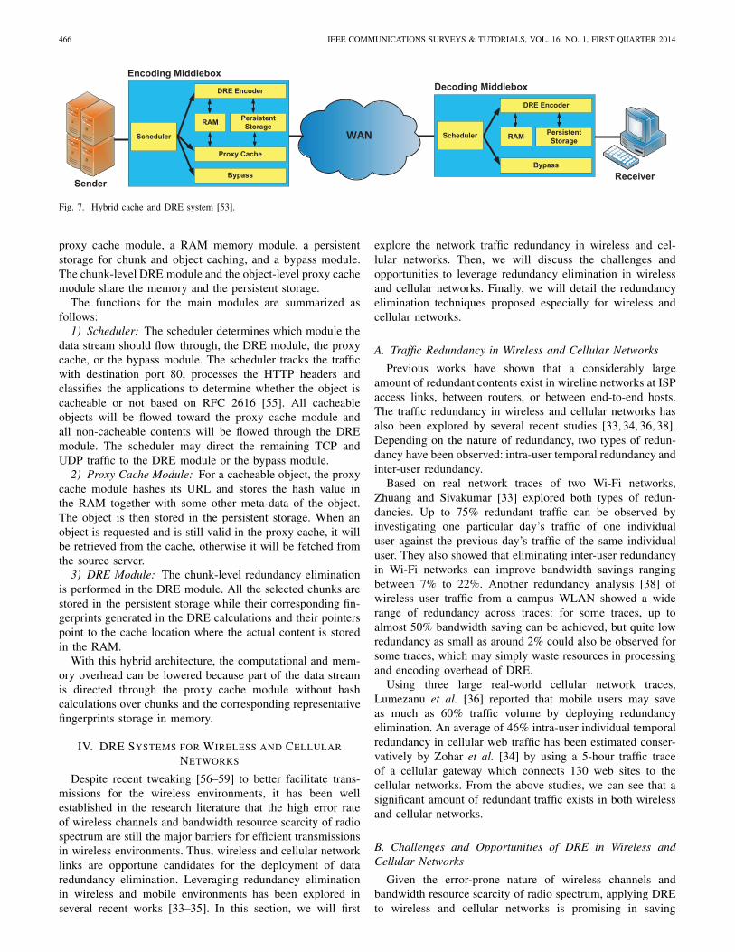
Traffic redundancy elimination can work on different gran-ularity levels: object level or chunk level. Object-level cacheprovides less bandwidth saving gains than chunk-level re-dundancy elimination. However, chunk-level DRE techniqueshave limitations in computational speed, memory and stor-age overhead. Chunk-level DRE computational overhead maybecome a bottleneck [54], especially in higher bandwidthlinks. A hybrid chunk and object level redundancy eliminationtechnique has been proposed for web optimization in [53].Fig. 7 shows the architecture of the proposed hybrid DREsystem. Two middleboxes, the encoding middlebox close tothe source and the decoding middlebox near the destination,work cooperatively over a wide-area network (WAN) to re-move the redundant traffic. The encoding middlebox consistsof a scheduler, a chunk-level DRE module, an object-level
466 IEEE COMMUNICATIONS SURVEYS & TUTORIALS, VOL. 16, NO. 1, FIRST QUARTER 2014
WAN
ReceiverSender
Scheduler
Proxy Cache
RAM PersistentStorage
DRE Encoder
Encoding MiddleboxDecoding Middlebox
Bypass
Scheduler RAM PersistentStorage
DRE Encoder
Bypass
Fig. 7. Hybrid cache and DRE system [53].
proxy cache module, a RAM memory module, a persistentstorage for chunk and object caching, and a bypass module.The chunk-level DRE module and the object-level proxy cachemodule share the memory and the persistent storage.
The functions for the main modules are summarized asfollows:
1) Scheduler: The scheduler determines which module thedata stream should flow through, the DRE module, the proxycache, or the bypass module. The scheduler tracks the trafficwith destination port 80, processes the HTTP headers andclassifies the applications to determine whether the object iscacheable or not based on RFC 2616 [55]. All cacheableobjects will be flowed toward the proxy cache module andall non-cacheable contents will be flowed through the DREmodule. The scheduler may direct the remaining TCP andUDP traffic to the DRE module or the bypass module.
2) Proxy Cache Module: For a cacheable object, the proxycache module hashes its URL and stores the hash value inthe RAM together with some other meta-data of the object.The object is then stored in the persistent storage. When anobject is requested and is still valid in the proxy cache, it willbe retrieved from the cache, otherwise it will be fetched fromthe source server.
3) DRE Module: The chunk-level redundancy eliminationis performed in the DRE module. All the selected chunks arestored in the persistent storage while their corresponding fin-gerprints generated in the DRE calculations and their pointerspoint to the cache location where the actual content is storedin the RAM.
With this hybrid architecture, the computational and mem-ory overhead can be lowered because part of the data streamis directed through the proxy cache module without hashcalculations over chunks and the corresponding representativefingerprints storage in memory.
IV. DRE SYSTEMS FOR WIRELESS AND CELLULARNETWORKS
Despite recent tweaking [56–59] to better facilitate trans-missions for the wireless environments, it has been wellestablished in the research literature that the high error rateof wireless channels and bandwidth resource scarcity of radiospectrum are still the major barriers for efficient transmissionsin wireless environments. Thus, wireless and cellular networklinks are opportune candidates for the deployment of dataredundancy elimination. Leveraging redundancy eliminationin wireless and mobile environments has been explored inseveral recent works [33–35]. In this section, we will first
explore the network traffic redundancy in wireless and cel-lular networks. Then, we will discuss the challenges andopportunities to leverage redundancy elimination in wirelessand cellular networks. Finally, we will detail the redundancyelimination techniques proposed especially for wireless andcellular networks.
A. Traffic Redundancy in Wireless and Cellular Networks
Previous works have shown that a considerably largeamount of redundant contents exist in wireline networks at ISPaccess links, between routers, or between end-to-end hosts.The traffic redundancy in wireless and cellular networks hasalso been explored by several recent studies [33, 34, 36, 38].Depending on the nature of redundancy, two types of redun-dancy have been observed: intra-user temporal redundancy andinter-user redundancy.
Based on real network traces of two Wi-Fi networks,Zhuang and Sivakumar [33] explored both types of redun-dancies. Up to 75% redundant traffic can be observed byinvestigating one particular day’s traffic of one individualuser against the previous day’s traffic of the same individualuser. They also showed that eliminating inter-user redundancyin Wi-Fi networks can improve bandwidth savings rangingbetween 7% to 22%. Another redundancy analysis [38] ofwireless user traffic from a campus WLAN showed a widerange of redundancy across traces: for some traces, up toalmost 50% bandwidth saving can be achieved, but quite lowredundancy as small as around 2% could also be observed forsome traces, which may simply waste resources in processingand encoding overhead of DRE.
Using three large real-world cellular network traces,Lumezanu et al. [36] reported that mobile users may saveas much as 60% traffic volume by deploying redundancyelimination. An average of 46% intra-user individual temporalredundancy in cellular web traffic has been estimated conser-vatively by Zohar et al. [34] by using a 5-hour traffic traceof a cellular gateway which connects 130 web sites to thecellular networks. From the above studies, we can see that asignificant amount of redundant traffic exists in both wirelessand cellular networks.
B. Challenges and Opportunities of DRE in Wireless andCellular Networks
Given the error-prone nature of wireless channels andbandwidth resource scarcity of radio spectrum, applying DREto wireless and cellular networks is promising in saving
ZHANG and ANSARI: ON PROTOCOL-INDEPENDENT DATA REDUNDANCY ELIMINATION 467
bandwidth and improving network performance. However,unlike wire networks, wireless and mobile environments ex-hibit unique challenges and opportunities in the context ofredundancy elimination. The broadcast nature of wireless com-munication makes it easier to eliminate inter-user redundancyby traffic overhearing. On the other hand, high packet lossrate, user mobility and some MAC layer characteristics couldimpose severe challenges to DRE efficiency in the wirelessenvironment.
Halepovic et al. [38] explored the effectiveness of DRE inwireless local area networks (WLANs) and they also exploredspecific issues affecting DRE performance in WLAN. Theirresults indicate that the effectiveness of DRE is lower thanthat of Ethernet due to higher physical channel error ratesin WLANs than in Ethernet, smaller proportion of IP traffic,and MAC-layer characteristics, such as longer MAC headers,control and management frames, retransmission, and framedrops.
Packet loss in the wireless environment due to the trans-mission error over the air interface, insufficient buffer sizesor communication congestion are normal in wireless environ-ments. The high packet loss rate makes it difficult to applyDRE in wireless and cellular networks. The effects of packetloss on redundancy elimination, in terms of bandwidth savingsand DRE decoding errors, in cellular wireless networks havebeen explored in [36]. They reported that DRE could bedisrupted by losing only a few packets. Packet loss maycause DRE decoding errors, which will prevent receivers fromreconstructing the original packets.
C. DRE Algorithms for Wireless and Cellular NetworksIn this section, we will review most of DRE algorithms
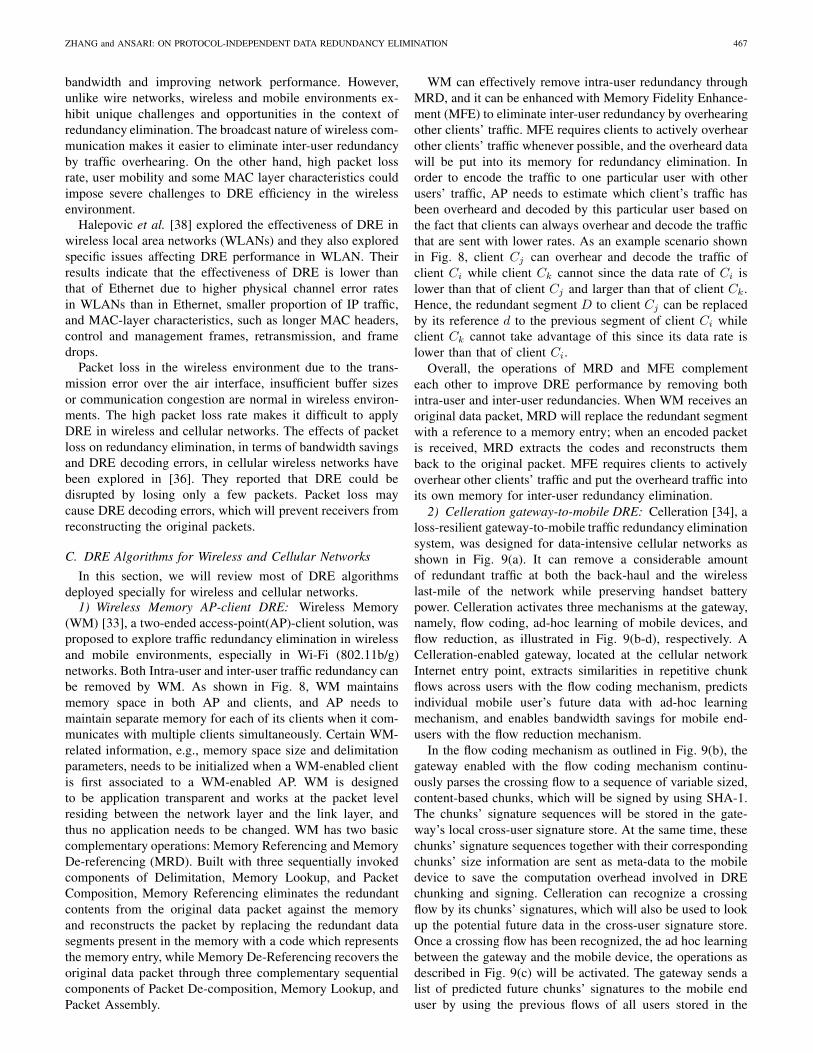
deployed specially for wireless and cellular networks.1) Wireless Memory AP-client DRE: Wireless Memory
(WM) [33], a two-ended access-point(AP)-client solution, wasproposed to explore traffic redundancy elimination in wirelessand mobile environments, especially in Wi-Fi (802.11b/g)networks. Both Intra-user and inter-user traffic redundancy canbe removed by WM. As shown in Fig. 8, WM maintainsmemory space in both AP and clients, and AP needs tomaintain separate memory for each of its clients when it com-municates with multiple clients simultaneously. Certain WM-related information, e.g., memory space size and delimitationparameters, needs to be initialized when a WM-enabled clientis first associated to a WM-enabled AP. WM is designedto be application transparent and works at the packet levelresiding between the network layer and the link layer, andthus no application needs to be changed. WM has two basiccomplementary operations: Memory Referencing and MemoryDe-referencing (MRD). Built with three sequentially invokedcomponents of Delimitation, Memory Lookup, and PacketComposition, Memory Referencing eliminates the redundantcontents from the original data packet against the memoryand reconstructs the packet by replacing the redundant datasegments present in the memory with a code which representsthe memory entry, while Memory De-Referencing recovers theoriginal data packet through three complementary sequentialcomponents of Packet De-composition, Memory Lookup, andPacket Assembly.
WM can effectively remove intra-user redundancy throughMRD, and it can be enhanced with Memory Fidelity Enhance-ment (MFE) to eliminate inter-user redundancy by overhearingother clients’ traffic. MFE requires clients to actively overhearother clients’ traffic whenever possible, and the overheard datawill be put into its memory for redundancy elimination. Inorder to encode the traffic to one particular user with otherusers’ traffic, AP needs to estimate which client’s traffic hasbeen overheard and decoded by this particular user based onthe fact that clients can always overhear and decode the trafficthat are sent with lower rates. As an example scenario shownin Fig. 8, client Cj can overhear and decode the traffic ofclient Ci while client Ck cannot since the data rate of Ci islower than that of client Cj and larger than that of client Ck.Hence, the redundant segment D to client Cj can be replacedby its reference d to the previous segment of client Ci whileclient Ck cannot take advantage of this since its data rate islower than that of client Ci.
Overall, the operations of MRD and MFE complementeach other to improve DRE performance by removing bothintra-user and inter-user redundancies. When WM receives anoriginal data packet, MRD will replace the redundant segmentwith a reference to a memory entry; when an encoded packetis received, MRD extracts the codes and reconstructs themback to the original packet. MFE requires clients to activelyoverhear other clients’ traffic and put the overheard traffic intoits own memory for inter-user redundancy elimination.
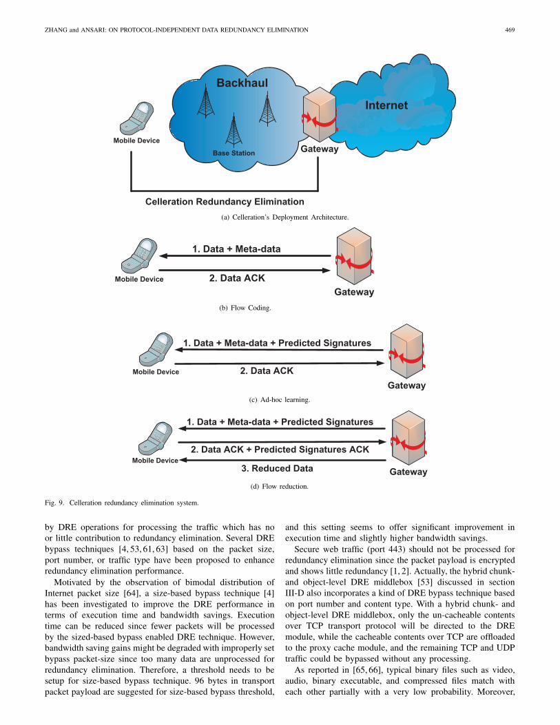
2) Celleration gateway-to-mobile DRE: Celleration [34], aloss-resilient gateway-to-mobile traffic redundancy eliminationsystem, was designed for data-intensive cellular networks asshown in Fig. 9(a). It can remove a considerable amountof redundant traffic at both the back-haul and the wirelesslast-mile of the network while preserving handset batterypower. Celleration activates three mechanisms at the gateway,namely, flow coding, ad-hoc learning of mobile devices, andflow reduction, as illustrated in Fig. 9(b-d), respectively. ACelleration-enabled gateway, located at the cellular networkInternet entry point, extracts similarities in repetitive chunkflows across users with the flow coding mechanism, predictsindividual mobile user’s future data with ad-hoc learningmechanism, and enables bandwidth savings for mobile end-users with the flow reduction mechanism.
In the flow coding mechanism as outlined in Fig. 9(b), thegateway enabled with the flow coding mechanism continu-ously parses the crossing flow to a sequence of variable sized,content-based chunks, which will be signed by using SHA-1.The chunks’ signature sequences will be stored in the gate-way’s local cross-user signature store. At the same time, thesechunks’ signature sequences together with their correspondingchunks’ size information are sent as meta-data to the mobiledevice to save the computation overhead involved in DREchunking and signing. Celleration can recognize a crossingflow by its chunks’ signatures, which will also be used to lookup the potential future data in the cross-user signature store.Once a crossing flow has been recognized, the ad hoc learningbetween the gateway and the mobile device, the operations asdescribed in Fig. 9(c) will be activated. The gateway sends alist of predicted future chunks’ signatures to the mobile enduser by using the previous flows of all users stored in the
468 IEEE COMMUNICATIONS SURVEYS & TUTORIALS, VOL. 16, NO. 1, FIRST QUARTER 2014
Rj = 2 Mbps
Memory De-referencing
Memory Referencing
WM
WM
Ri = 1Mbps
Rk = 0.5 Mbps
Client i
Client k
Delimitation MemoryLookup
PacketComposition
Segments CodesData Packet Encoded Packet
De-Composition MemoryLookup
PacketAssembly
Codes SegmentsEncoded Packet Data Packet
Memory
WMs
AP
WM
Client j
Wireless Memory Components
Data D
Code d
Data D
Fig. 8. Illustration of Wireless Memory [33].
cross-user signature store. The mobile end device will respondwith a list of time-limited approvals by checking whether thecorresponding data of the predicted chunks’ signatures are inits local cache or not. If the ad-hoc learning indicates thatsome predicted data chunks already exist in the cache of themobile device, the flow reduction mechanism of Cellerationas illustrated in Fig. 9(d) will be activated by refraining thegateway from forwarding the approved chunks to the mobiledevice as they arrive at the gateway. Thus, the redundant trafficover the transmission path between the gateway and the mobiledevice can be removed.
3) REfactor: Previous efforts on leveraging the broadcastnature of the wireless environment in redundancy eliminationfocused on overhearing entire packets, which may limit thebenefits of fully leveraging opportunistic overhearing. By de-ploying opportunistic overhearing over sub-packet level packetcontent, REfactfor [35] can improve the IP-layer redundancyelimination performance. REfactor uses the MAXP algorithmwith Chunk-Match for data fingerprinting. As an improvement,it incorporates a self-addressing mechanism wherein a chunkcan identify its storage location in the cache based on thechunk content, and a removed chunk can be identified by itslocation in the cache. Thus, the encoder can only maintainthe chunk hashes in a hash table and the decoder can onlymaintains the chunks in a FIFO cache. Based on the fact that
overhearing probabilities are time-varying and are different fordifferent clients, REfactor introduces a reception probabilityvector for each chunk entry stored in the hash table at the AP.By using this reception probability vector, REfactor estimatesthe expected benefit, which is measured as the reductionin transmission time by eliminating a redundant chunk. Ifthe expected benefit exceeds some predefined threshold, theredundant chunk will be removed. The retransmission-baseddecoding error recovery scheme is deployed in REfactor. If acache miss hit occurs at the receiver, the receiver requests achunk retransmission from the sender.
V. OTHER TECHNIQUES TO ENHANCE REDUNDANCYELIMINATION PERFORMANCE
Several techniques [4, 39, 60–62], such as DRE bypass tech-niques and content-aware chunk selection, have been proposedto enhance the DRE performance in terms of computationaloverhead, execution time and bandwidth savings. In thissection, we investigate the effects of these techniques on theperformance of DRE.
A. Bypass Techniques
The goal of DRE bypass techniques is to save the resourceoverhead including computation, memory and storage, induced
ZHANG and ANSARI: ON PROTOCOL-INDEPENDENT DATA REDUNDANCY ELIMINATION 469
Internet
Mobile Device
Backhaul
Base Station Gateway
Celleration Redundancy Elimination(a) Celleration’s Deployment Architecture.
Mobile Device
Gateway
1. Data + Meta-data
2. Data ACK
(b) Flow Coding.
Mobile Device
Gateway
1. Data + Meta-data + Predicted Signatures
2. Data ACK
(c) Ad-hoc learning.
Mobile DeviceGateway
1. Data + Meta-data + Predicted Signatures
2. Data ACK + Predicted Signatures ACK
3. Reduced Data
(d) Flow reduction.
Fig. 9. Celleration redundancy elimination system.
by DRE operations for processing the traffic which has noor little contribution to redundancy elimination. Several DREbypass techniques [4, 53, 61, 63] based on the packet size,port number, or traffic type have been proposed to enhanceredundancy elimination performance.
Motivated by the observation of bimodal distribution ofInternet packet size [64], a size-based bypass technique [4]has been investigated to improve the DRE performance interms of execution time and bandwidth savings. Executiontime can be reduced since fewer packets will be processedby the sized-based bypass enabled DRE technique. However,bandwidth saving gains might be degraded with improperly setbypass packet-size since too many data are unprocessed forredundancy elimination. Therefore, a threshold needs to besetup for size-based bypass technique. 96 bytes in transportpacket payload are suggested for size-based bypass threshold,
and this setting seems to offer significant improvement inexecution time and slightly higher bandwidth savings.
Secure web traffic (port 443) should not be processed forredundancy elimination since the packet payload is encryptedand shows little redundancy [1, 2]. Actually, the hybrid chunk-and object-level DRE middlebox [53] discussed in sectionIII-D also incorporates a kind of DRE bypass technique basedon port number and content type. With a hybrid chunk- andobject-level DRE middlebox, only the un-cacheable contentsover TCP transport protocol will be directed to the DREmodule, while the cacheable contents over TCP are offloadedto the proxy cache module, and the remaining TCP and UDPtraffic could be bypassed without any processing.
As reported in [65, 66], typical binary files such as video,audio, binary executable, and compressed files match witheach other partially with a very low probability. Moreover,
470 IEEE COMMUNICATIONS SURVEYS & TUTORIALS, VOL. 16, NO. 1, FIRST QUARTER 2014
these binary files comprise the biggest portion of the totalamount of traffic in the Internet [67]. Considering these twoInternet traffic properties, a traffic-type based bypass technique[61, 63] was proposed to reduce the computational overheadincurred by DRE while keeping the comparable bandwidthsaving gains with the bypass technique disabled. This traffic-type based bypass technique incorporates deep packet inspec-tion (DPI). The bypass module tracks the traffic types of eachflow by parsing the HTTP header for the “mime-type” headerfield, and marks any flow as “binary-flow” whose contenthas been identified as “audio”, “video”, or “application” inthe header field of “mime-type”. All of the flows marked as“binary-flow” are passed without any redundancy eliminationprocessing. By applying this traffic-type based DRE bypasstechnique to the traffic load mixed with text and binaryfiles, the CPU processing load can be reduced greatly whileachieving the comparable bandwidth saving gains with thisbypass technique disabled. At the same time, the total numbersof memory and storage access are also decreased since fewerdata are processed for redundancy elimination.
B. Non-uniform sampling
The non-uniform chunk popularity [66] enables a non-uniform sampling technique to improve DRE performance.The chunks with high-redundant contents are preferred forredundancy elimination than the chunks with low-redundantcontents. Thus, DRE performance can be improved by intro-ducing multiple sampling rates and adjusting the sampling rateaccording to the chunk content rather than with a single sam-pling rate. In general, text data is more redundant than non-text data [65, 66]. In [4], a non-uniform sampling approachwas proposed based on the proportion of plain-text characterswithin a data chunk: higher sampling rate is applied to thedata content that has higher proportion of text characters.
C. Overlap
As investigated in [4], allowing chunk overlap can improvebandwidth savings by 9-14% with relative cost in executiontime. Allowing any overlap may result in unacceptable ex-ecution time; hence, half-chunk overlap is suggested as athreshold for chunk overlapping.
VI. CONCLUSION
In this paper, we have reviewed current state of the artof protocol-independent redundancy elimination. We have de-tailed the system architecture and main processing proceduresincurred in protocol-independent DRE techniques. The majormechanisms involved in DRE techniques, including finger-printing, cache management, chunk matching, and decodingerror recovery, have been discussed. For each mechanism, dif-ferent approaches have been reviewed. We have also presentedseveral redundancy elimination systems deployed in wireline,wireless and cellular networks, respectively. Moreover, someother techniques to enhance the DRE performance such asDRE bypass techniques, non-uniform sampling, and chunkoverlap, have been discussed. This survey enables researchersand practitioners to jump-start their DRE projects. Fast and
efficient redundant content identification methods to reducethe computational cost involved in identifying the redundantcontents and to improve the redundant content eliminationefficiency are extremely critical and still hot topics for DREresearch. Also, the balance between the computational costand redundant content elimination efficiency has not beensufficiently addressed in the previous works and needs furtherstudies. In Reference [68], a redundancy elimination methodhas been proposed to remove duplicated contents at the blocklevel by applying aspects of several techniques, includingduplicate block elimination, delta encoding and data compres-sion. Particularly, it first suppresses the identical blocks, andthen performs delta encoding on similar blocks with sufficientredundancy, and finally compresses the remaining blocks thatdo not benefit from the delta encoding. The performance ofthe proposed redundancy elimination method was, however,not provided in [68]. While individual redundancy eliminationtechniques such as compression, delta encoding, caching andDRE techniques may be proven to be effective within theirrespective application scenarios, further investigation is neededto collectively incorporate and exploit multiple techniques inbuilding a complete system.
REFERENCES
[1] N. T. Spring and D. Wetherall, “A Protocol-Independent Techniquefor Eliminating Redundant Network Traffic,” in Proc. SIGCOMM,Stockholm, Sweden, 2000, pp. 87–95.
[2] A. Anand, C. Muthukrishnan, A. Akella, and R. Ramjee, “Redundancyin Network Traffic: Findings and Implications,” in Proc. 11th Interna-tional Joint Conference on Measurement and Modeling of ComputerSystems, Seattle, WA, USA, 2009, pp. 37–48.
[3] B. Aggarwal, A. Akella, A. Anand, A. Balachandran, P. Chitnis,C. Muthukrishnan, R. Ramjee, and G. Varghese, “EndRE: an End-System Redundancy Elimination Service for Enterprises,” in Proc. 7thUSENIX conference on Networked systems design and implementation,San Jose, California, 2010, pp. 28–28.
[4] E. Halepovic, C. Williamson, and M. Ghaderi, “Enhancing RedundantNetwork Traffic Elimination,” Computer Networks, vol. 56, no. 2, pp.795–809, Feb. 2012.
[5] Cisco, “Cisco Visual Networking Index: Forecast and Methodology,2010-2015,” http://www.cisco.com/en/US/solutions/collateral/ns341/ns525/ns537/ns705/ns827/white paper c11-481360.pdf.
[6] W. J. Bolosky, S. Corbin, D. Goebel, and J. R. Douceur, “Single InstanceStorage in Windows 2000,” in Proc. 4th conference on USENIX WindowsSystems Symposium, Washington, Aug. 2000, pp. 13–24.
[7] J. R. Douceur, A. Adya, W. J. Bolosky, D. Simon, and M. Theimer,“Reclaiming Space from Duplicate Files in a Serverless DistributedFile System,” in Proc. 22 nd International Conference on DistributedComputing Systems, Vienna, Austria, July 2002, pp. 617–624.
[8] Q. He, Z. Li, and X. Zhang, “Data Deduplication Techniques,” inProc. International Conference on Future Information Technology andManagement Engineering (FITME), Oct. 2010, pp. 430 –433.
[9] A. Anand, A. Gupta, A. Akella, S. Seshan, and S. Shenker, “PacketCaches on Routers: the Implications of Universal Redundant TrafficElimination,” in Proc. SIGCOMM, Seattle, WA, USA, 2008, pp. 219–230.
[10] A. Anand, V. Sekar, and A. Akella, “SmartRE: an Architecture for Coor-dinated Network-Wide Redundancy Elimination,” SIGCOMM ComputerCommunication Review, vol. 39, pp. 87–98, August 2009.
[11] G. Lu, Y. Jin, and D. Du, “Frequency Based Chunking for Data De-Duplication,” in Proc. Modeling, Analysis Simulation of Computer andTelecommunication Systems, Aug. 2010, pp. 287 –296.
[12] S. Saha, A. Lukyanenko, and A. Yla-Jaaski, “Combiheader: Minimizingthe number of shim headers in redundancy elimination systems,” in Proc.INFOCOM workshops, April 2011, pp. 798 –803.
[13] S. Quinlan and S. Dorward, “Venti: A New Approach to ArchivalData Storage,” in Proc. 1st USENIX Conference on File and StorageTechnologies (FAST), 2002, pp. 89 – 101.
ZHANG and ANSARI: ON PROTOCOL-INDEPENDENT DATA REDUNDANCY ELIMINATION 471
[14] A. T. Clements, I. Ahmad, M. Vilayannur, and J. Li, “DecentralizedDeduplication in SAN Cluster File Systems,” in Proc. USENIX Annualtechnical conference, San Diego, California, June 2009.
[15] C. Constantinescu, J. Pieper, and T. Li, “Block Size Optimizationin Deduplication Systems,” in Proc. Data Compression Conference,Snowbird, Utah, March 16-18, 2009.
[16] E. Lev-Ran, I. Cidon, and I. Z. Ben-Shaul, “Method and Apparatusfor Reducing Network Traffic over Low Bandwidth Links,” Patent US7 636 767, November 2009, File: November 2005.
[17] Juniper Networks, “Application Acceleration,” http://www.juniper.net/us/en/products-services/application-acceleration/.
[18] BlueCoat Systems, “WAN Optimization,” http://www.bluecoat.com/products.
[19] S. McCanne and M. J. Demmer, “Content-based Segmentation Schemefor Data Compression in Storage and Transmission Including Hierar-chical Segment Representation,” Patent US 6 828 925, December 2004,File: December 2003.
[20] M. Al-laham and I. M. M. E. Emary, “Comparative study betweenvarious algorithms of data compression techniques,” International J.Computer Science and Network Security, vol. 7, no. 4, April 2007.
[21] D. Zeng, F.-Y. Wang, and M. Liu, “Efficient Web Content DeliveryUsing Proxy Caching Techniques,” IEEE Trans. Syst. Man Cybern. C,Appl. Rev., vol. 34, no. 3, pp. 270–280, Aug. 2004.
[22] PeerApp, “Video and P2P Caching,” http://www.peerapp.com/Technology/VideoCaching.aspx.
[23] A. Wolman, G. Voelker, N. Sharma, N. Cardwell, M. Brown, T. Landray,D. Pinnel, A. Karlin, and H. Levy, “Organization-based Analysis ofWeb-object Sharing and Caching,” in Proc. 2nd conference on USENIXSymposium on Internet Technologies and Systems (USITS’99), Boulder,Colorado, October 1999, pp. 25–36.
[24] “Squid Web proxy cache,” http://www.squid-cache.org/.[25] B. C. Housel and D. B. Lindquist, “WebExpress: a System for Op-
timizing Web Browsing in a Wireless Environment,” in Proc. 2ndannual International Conference on Mobile Computing and Networking(MobiCom’96), November 1996.
[26] J. C. Mogul, F. Douglis, A. Feldmann, and B. Krishnamurthy, “PotentialBenefits of Delta Encoding and Data Compression for HTTP,” in Proc.ACM SIGCOMM, Cannes, France, September 1997, pp. 181–194.
[27] F. Douglis and A. Iyengar, “Application-specific Delta-encoding via Re-semblance Detection,” in Proc. USENIX Annual Technical Conference,San Antonio, TX, June 2003, pp. 113–126.
[28] Rsync, http://rsync.samba.org/.[29] N. Mandagere, P. Zhou, M. A. Smith, and S. Uttamchandani, “Demysti-
fying Data Deduplication,” in Proc. Middleware Conference Companion,Leuven, Belgium, Dec. 1-5, 2008, pp. 12–17.
[30] Y. Zhang, N. Ansari, M. Wu, and H. Yu, “On wide area networkoptimization,” IEEE Communi. Surveys Tutorials, vol. 14, no. 4, pp.1090–1113, 2012.
[31] T. Han, N. Ansari, M. Wu, and H. Yu, “On accelerating content deliveryin mobile networks,” IEEE Commun. Surveys Tutorials, vol. PP, no. 99,pp. 1–20, 2012.
[32] Y. Song, K. Guo, and L. Gao, “Redundancy-Aware Routing with Lim-ited Resources,” in Proc. 19th International Conference on ComputerCommunications and Networks (ICCCN), Aug. 2010, pp. 1–6.
[33] Z. Zhuang and R. Sivakumar, “Wireless Memory: Eliminating Commu-nication Redundancy in Wi-Fi Networks,” in Proc. IEEE InternationalSymposium on World of Wireless, Mobile and Multimedia Networks(WoWMoM), Lucca, Tuscany, Italy, June 20-24, 2011.
[34] E. Zohar, I. Cidon, and O. O. Mokryn, “Celleration: Loss-ResilientTraffic Redundancy Elimination for Cellular Data,” in Proc. 13th In-ternaltional Workshop on Mobile Computing Systems and Applications(HotMobile), San Diego, California, Feb. 28-29, 2012, pp. 10:1–10:6.
[35] S.-H. Shen, A. Gember, A. Anand, and A. Akella, “REfactor-ing ContentOverhearing to Improve Wireless Performance,” in Proc. 17th AnnualInternational Conference on Mobile Computing and Networking, LasVegas, Nevada, USA, 2011, pp. 217–228.
[36] C. Lumezanu, K. Guo, N. Spring, and B. Bhattacharjee, “The Effect ofPacket Loss on Redundancy Elimination in Cellular Wireless Networks,”in Proc. 10th annual Conference on Internet Measurement (IMC),Melbourne, Australia, 2010, pp. 294–300.
[37] E. Zohar, I. Cidon, and O. O. Mokryn, “The Power of Prediction: CloudBandwidth and Cost Reduction,” in Proc. SIGCOMM, Toronto, Canada,Aug. 15-19, 2011.
[38] E. Halepovic, M. Ghaderi, and C. Williamson, “On the Performance ofRedundant Traffic Elimination in WLANs,” in Proc. IEEE InternationalConference on Communications, Ottawa, Canada, June 2012.
[39] M. Martynov, “Challenges for High-Speed Protocol-Independent Redun-dancy Eliminating Systems,” in Proc. 18th Internatonal Conference on
Computer Communications and Networks (ICCCN), Aug. 2009, pp. 1–6.
[40] U. Manber, “Finding Similar Files in a Large File System,” in Proc.USENIX Winter 1994 Technical Conference (WTEC’94), San Francisco,California, January 1994.
[41] A. Broder, “On the Resemblance and Containment of Documents,” inProc. Compression and Complexity of Sequences (SEQUENCES’97),Washington, DC, USA, 1997, pp. 21–29.
[42] M. O. Rabin, “Fingerprinting by Random Polynomials,” Center forResearch in Computing Technology, Harvard University, Tech. Rep. TR-15-81, 1981.
[43] S. Schleimer, D. S. Wilkerson, and A. Aiken, “Winnowing: LocalAlgorithms for Document Fingerprinting,” in Proc. 2003 ACM SIGMODinternational conference on Management of Data (SIGMOD), SanDiego, California, 2003, pp. 76–85.
[44] N. Bjørner, A. Blass, and Y. Gurevich, “Content-Dependent Chunkingfor Differential Compression, the Local Maximum Approach,” http://research.microsoft.com/en-us/um/people/gurevich/Opera/190.pdf, Mi-crosoft Research, Tech. Rep. 109, July 2007.
[45] “Jenkins Hash,” http://burtleburtle.net/bob/c/lookup3.c.[46] E. Halepovic, C. Williamson, and M. Ghaderi, “DYNABYTE: A
Dynamic Sampling Algorithm for Redundant Content Detection,” inProc. 20th International Conference on Computer Communications andNetworks (ICCCN), Maui, Hawaii, USA, July 31 - Aug. 4, 2011.
[47] M. G. Emir Halepovic, Carey Williamson, “Low-Overhead DynamicSampling for Redundant Traffic Elimination,” vol. 7, no. 1, Jan. 2012.
[48] S. Ihm, K. Park, and V. S. Pai, “Wide-area Network Acceleration forthe Developing World,” in Proc. 2010 USENIX conference on USENIXannual technical conference, Boston, MA, 2010, pp. 18–18.
[49] E. Zohar, O. O. Mokryn, and I. Cidon, “PACK: Speculative TCPTraffic Redundancy Elimination,” Tech. Rep. CCIT Report #770, July2010. [Online]. Available: http://webee.technion.ac.il/publication-link/index/id/569/abstract/1.
[50] D. G. Thaler and C. V. Ravishankar, “Using Name-based Mappings toIncrease Hit Rates,” IEEE/ACM Trans. Netw., vol. 6, no. 1, pp. 1–14,Feb. 1998.
[51] J. Luo, D. Ye, X. Liu, and M. Fan, “A survey of Multicast RoutingProtocols for Mobile Ad-Hoc Networks,” IEEE Commun. SurveysTutorials, vol. 11, no. 1, pp. 78 –91, Quarter 2009.
[52] V. Sekar, M. K. Reiter, W. Willinger, H. Zhang, R. R. Kompella,and D. G. Andersen, “cSamp: A System for Network-Wide FlowMonitoring,” in Proc. 5th USENIX NSDI, San Francisco, CA, Apr. 2008.
[53] I. Papapanagiotou, R. D. Callaway, and M. Devetsikiotis, “Chunk andObject Level Deduplication for Web Optimization: A Hybrid Approach,”in Proc. of IEEE International Conference on Communications (ICC),Ottawa, Canada, June 10-15, 2012.
[54] M. Martynov, “Experimental Study of Protocol-independent Redun-dancy Elimination Algorithms,” in Proc. first joint WOSP/SIPEW inter-national conference on Performance Engineering, San Jose, California,USA, 2010, pp. 141–146.
[55] R. Fielding, J. Gettys, J. Mogul, H. Frystyk, L. Masinter, P. Leach, andT. Berners-Lee, “RFC 2616: Hypertext Transfer Protocol – HTTP/1.1,”June 1999. [Online]. Available: http://www.ietf.org/rfc/rfc2616.txt
[56] K. Xu, Y. Tian, and N. Ansari, “TCP-Jersey for wireless IP communi-cations,” IEEE J. Sel. Areas Commun., vol. 22, no. 4, pp. 747 – 756,May 2004.
[57] Y. Tian, K. Xu, and N. Ansari, “TCP in wireless environments: problemsand solutions,” IEEE Commun. Mag., vol. 43, no. 3, pp. S27 – S32,March 2005.
[58] K. Xu, Y. Tian, and N. Ansari, “Improving TCP Performance inIntegrated Wireless Communications Networks,” Computer Networks,vol. 47, no. 2, pp. 219–237, February 2005.
[59] T. Han, N. Ansari, M. Wu, and H. Yu, “Tcp-mobile edge: Acceleratingdelivery in mobile networks,” in Proc. IEEE International Conference onCommunications (ICC), Ottawa, Canada, June 10-15, 2012, pp. 5393–5397.
[60] K. Tangwongsan, H. Pucha, D. G. Andersen, and M. Kaminsky, “Effi-cient Similarity Estimation for Systems Exploiting Data Redundancy,” inProc. 29th conference on Information Communications (INFOCOM’10),San Diego, California, USA, 2010, pp. 1487–1495.
[61] S. Saha, “On Reducing the Processing Load of Redundancy EliminationAlgorithms,” in Proc. IEEE GLOBECOM Workshops, Dec. 2011, pp.1106 –1110.
[62] W. Xia, H. Jiang, D. Feng, and L. Tian, “Accelerating Data Dedu-plication by Exploiting Pipelining and Parallelism with Multicore orManycore Processors,” in Proc. 10th USENIX Conference on File andStorage Technologies (FAST), San Jose, CA, USA, Feb. 14-17, 2012.
472 IEEE COMMUNICATIONS SURVEYS & TUTORIALS, VOL. 16, NO. 1, FIRST QUARTER 2014
[63] Y. Zhang, N. Ansari, M. Wu, and H. Yu, “SDRE: Selective dataredundancy elimination for resource constrained hosts,” in Proc. 2012IEEE Global Communications Conference (GLOBECOM), Anaheim,CA, USA, 3-7 Dec. 2012, pp. 1865–1870.
[64] M. Arlitt and C. Williamson, “Internet Web servers: Workload Char-acterization and Performance Implications,” IEEE/ACM Trans. Netw.,vol. 5, no. 5, pp. 631–645, Oct. 1997.
[65] H. Pucha, D. G. Andersen, and M. Kaminsky, “Exploiting Similarity forMulti-source Downloads Using File Handprints,” in Proc. 4th USENIXconference on Networked Systems Design & Implementation (NSDI’07),Cambridge, MA, 2007.
[66] E. Halepovic, C. Williamson, and M. Ghaderi, “Exploiting Non-Uniformities in Redundant Traffic Elimination,” Department ofComputer Science, University of Calgary, Tech. Rep., 2010.[Online]. Available: https://dspace.ucalgary.ca/bitstream/1880/48155/1/2010-971-20.pdf
[67] M. E. Crovella, M. S. Taqqu, and A. Bestavros, “Heavy-tailed Proba-bility Distributions in the World Wide Web,” in A Practical Guide toHeavy Tails: Statistical Techniques and Applications, 1998, pp. 3–25.
[68] F. Douglis, P. Kulkarni, J. D. LaVoie, and J. M. Tracey, “Method andApparatus for Data Redundancy Elimination at the Block Level,” PatentUS 20 050 131 939 A1, Jun. 16, 2005, Filed on Dec. 16, 2003.
Yan Zhang (S’10) received the B.E. and M.E. de-grees in Electrical Engineering from Shandong Uni-versity, Jinan, Shandong, China, in 2001 and 2004,respectively. She is currently pursuing the Ph.D. de-gree in Computer Engineering at the New Jersey In-stitute of Technology (NJIT), Newark. Her researchinterests include automatic modulation classificationalgorithms, distributed detection in sensor network,congestion control in data center networks, contentdelivery acceleration over wide area networks, andenergy-efficient networking.
Nirwan Ansari (S’78-M’83-SM’94-F’09) receivedhis BSEE (summa cum laude with a perfectGPA)from NJIT, MSEE from the University ofMichigan, Ann Arbor, and PhD from Purdue Uni-versity, West Lafayette, IN, USA. He joined NJITin 1988, where he is a Professor of electrical andcomputer engineering. He has also assumed variousadministrative positions at NJIT. He has been aVisiting (Chair/Honorary) Professor at several uni-versities. His current research focuses on variousaspects of broadband networks and multimedia com-
munications.Prof. Ansari has served on the editorial/advisory boards of eight journals.
He was elected to serve on the IEEE Communications Society (ComSoc)Board of Governors as a member-at-large (2013-2015) as well as the IEEERegion 1 Board of Governors as the IEEE North Jersey Section Chair. Hehas chaired ComSoc technical committees, and has been actively organiz-ing numerous IEEE international conferences/symposia/workshops, assumingleadership roles as Chair or TPC Chair.
Prof. Ansari has authored Computational Intelligence for Optimization(Springer 1997) with E.S.H. Hou, Media Access Control and Resource Allo-cation for Next Generation Passive Optical Networks (Springer, 2013) withJ. Zhang, and edited Neural Networks in Telecommunications (Springer1994)with B. Yuhas. He has also contributed to over 400 publications, over onethird of which were published in widely cited refereed journals/magazines. Hehas been granted over twenty U.S. patents. He has also guest-edited a numberof special issues, covering various emerging topics in communications andnetworking. He has been frequently selected to deliver keynote addresses,distinguished lectures, and tutorials. Some of his recent recognitions includeBest Paper awards, Excellence in Teaching Awards, the Thomas Alva EdisonPatent Award (2010), the NJ Inventors Hall of Fame Inventor of the YearAward (2012), and designation as a ComSoc Distinguished Lecturer (2006-2009).