on power fueling technology - nrc: home pagepg 13 new fuel transfer • fuel transfer to fueling...
TRANSCRIPT
On Power Fueling TechnologyPart 2: Current CANDU Design
By Diane Damario et al
Presented to US Nuclear Regulatory CommissionWashington, DC
September 3, 2003
Pg 2
Current CANDU Design and Experience• Horizontal pressure tube CANDU reactor design with
on-power fueling conceived in late 1950s• Prototype design, the 22 MWe Nuclear Power
Demonstration (NPD) brought into service in Ontario, Canada, in May 1962 (established viability of on-power fueling for commercial nuclear power plants)
• 206 MWe commercial demonstration plant, Douglas Point in Ontario, Canada, declared in service in September 1968
• RAPS-1&2 (Douglas Point type reactor) in India in-service by December 1973 and April 1981 respectively
• KANUPP (125 MWe improved version of NPD) in Pakistan, declared in-service in November 1972

Pg 3
• Pickering A (four 500 MWe units) in Ontario, Canada, in-service by June 1973
• Pickering B (sister station to Pickering B) in Ontario, Canada, in-service by February 1986
• Bruce A (four 750 MWe units) in Ontario, Canada, in-service by January 1979
• Bruce B (sister station to Bruce A) in Ontario, Canada, in-service by May 1987
• Darlington (four 850 MWe units) in Ontario, Canada, in-service by June 1993
Stations in Ontario

Pg 4
CANDU 6 Stations• Point Lepreau in New Brunswick, Canada: February 1983• Wolsong 1 in South Korea: April 1983• Gentilly 2 in Québec, Canada: October 1983• Embalse in Argentina: January 1984• Cernavoda 1 in Romania: December 1996• Wolsong-2 in South Korea: July 1997• Wolsong-3 in South Korea: July 1998• Wolsong-4 in South Korea: October 1999• Qinshan 1 (3A) in China: December 2002• Qinshan 2 (3B) in China: July 2003• Cernavoda 2 in Romania is under construction and scheduled to
be in-service in March 2007

Pg 5
A. New fuel transfer:− receipt, storage and inspection of new fuel bundles− loading of new fuel bundles into fueling machines
through new fuel port
Fuel Handling System(CANDU 6)

Pg 6
B. Fuel changing:− transfer of new fuel bundles to reactor face− insertion of new fuel into fuel channel− discharge of spent fuel from same channel− transfer of spent fuel to spent fuel port− requires 2 fueling machines - one each at upstream and
downstream ends of channel− fueling is with flow - direction of flow alternates in
adjacent channels
Fuel Handling System(CANDU 6)

Pg 7
Fuel Handling System(CANDU 6)
C. Spent fuel transfer:− discharge of spent fuel from fueling machine− transfer of spent fuel to spent fuel storage bay

Pg 8
New Fuel• Mainly stored in new fuel storage area in service building• Transferred in pallets through airlock to new fuel transfer
room in reactor building• Opened and unwrapped as individual fuel bundles• Moved to inspection table via bundle lifting tool attached to
air balance hoist• Size inspected with fuel spacer interlocking gauge• Checked for damage or foreign matter• 2 bundles placed in loading trough of transfer mechanism

Pg 9
Pg 10
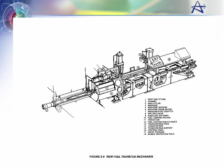
New Fuel Transfer Mechanism
• Mechanism magazine contains 7 channels− 6 for fuel− 1 for mechanism shield plug (shield plug normally in new fuel
port to reduce radiation into new fuel transfer room from spent fuel in FM)
Pg 11
New Fuel Transfer Mechanism
• Bundles transferred in pairs into magazine trough− with mechanism shield plug in place, air lock valve
opened− bundle pairs placed in trough− trough lid closed− bundles pushed into magazine by loading ram− magazine indexed and process repeated until required
number of bundles transferred to magazine− air lock valve closed

Pg 12
New Fuel Transfer Mechanism
• Air lock gate valve seals off magazine whenever fuel is not being loaded into magazine (prevents contamination of new fuel room from fueling machine head, maintenance lock or reactor vault)
Pg 13
New Fuel Transfer• Fuel transfer to fueling machine via new fuel port is
performed in air (i.e., D2O level in FM lowered) • Fueling machine clamps on to new fuel port, lowers its
D2O level and removes its snout plug• New fuel magazine rotated to shield plug station and
transfer ram advanced to remove shield plug from port and deposit in magazine

Pg 14
New Fuel Transfer
• Transfer between magazines:− fueling machine magazine rotates to empty fuel station while
new fuel magazine rotates to full station− transfer ram pushes 2 new fuel bundles into FM magazine− process repeated until fueling machine contains required
number of bundles• Shield plug re-installed into new fuel port and locked
Pg 15

Pg 16
Pg 17
Fueling Machine Head
• Remote controlled pressure vessel− Uses internal snout plug to seal vessel when not on channel/
port• Consists of the following major parts or mechanisms:
− Snout assembly− Magazine− Rams− Fuel separators

Pg 18
Snout Assembly
• Clamps to the fuel channel end fitting• Forms a pressure tight seal to contain heat transport
coolant (D2O)• Clamps onto new fuel port, spent fuel port, ancillary
port, or rehearsal facility port

Pg 19
Fuel Separators
• Separate the fuel bundles from the string or from the shield plug
• Allow fuel bundles to be stored in pairs

Pg 20
Magazine
• Has 12 tubes (chambers/stations) for:− fuel bundles (4 tubes)− shield plugs (2 tubes)− closure plugs (2 tubes)− guide sleeve and guide sleeve tool (1 tube)− ram adapter (1 tube)− FARE tool (1 tube)− snout plug (1 tube)
• One of the shield plug stations and the FARE tool station can be used for fuel, if required

Pg 21
Rams
• transfer fuel bundles, plugs, and guide sleeve between magazine and fuel channel
• 3 rams− B ram (mechanical)− latch ram (mechanical)− C ram (hydraulic)

Pg 22

Pg 23
Fueling Machine Support
• Fueling machine suspended from carriage• Carriage moves horizontally along rails on bridge and
maintenance lock tracks• Bridge supported by 2 columns and ball screw jacks
which move the fueling machine vertically through the bridge and carriage
• Fueling machine can reach any channel

Pg 24
Fueling Machine Support
• Final alignment provided by fine control positioning devices on the carriage
• Maintenance lock tracks line up with lowest bridge position to allow transfer of fueling machine into maintenance lock area for access to fuel ports and for servicing

Pg 25

Pg 26

Pg 27

Pg 28
Pg 29
Spent Fuel Transfer – Discharge Bay• Fueling Machine (FM) D2O level lowered and a pair of fuel
bundles raised above the water level to line up with the FM snout
• Un-cooled spent fuel bundles received in bundle pairs from FM via spent fuel port
• Elevator lowers bundles into water of discharge bay anddeposits them on transfer rack (normally 8 bundles but rack capacity is 12)
• Once all fuel bundles discharged onto transfer rack, rack transferred on discharge bay conveyor to containment gate
• Emergency spray cooling system activated if fuel in air too long

Pg 30
• Spent fuel port ball valves closed, containment gate opened and cart transferred from discharge conveyor to transfer canal conveyor
• Transfer canal conveyor carries cart to reception bay
Spent Fuel Transfer – Discharge Bay

Pg 31
Note: containment gate not shown

Pg 32
• Operator on reception bay walkway uses transfer rack handling tool to pick up loaded transfer rack from cart and places an empty rack on cart
• Empty rack and cart returned to discharge bay for next loading
• Loaded transfer rack placed on rack stand in reception bay
Spent Fuel Transfer – Reception Bay

Pg 33Note: containment gate not shown

Pg 34
• Bundles manually transferred individually from rack to spent fuel storage tray with a bundle lifting tool
• Each storage trays holds a total of 24 bundles placed in 2 rows
• Tray moved onto manually operated storage bay conveyor for transfer to storage bay
Spent Fuel Transfer – Discharge Bay

Pg 35
Note: containment gate not shown

Pg 36
• Operator on manbridge picks up tray using hoist on manbridge and tray lifting tool and deposits on base support located on bay floor
• Trays are stacked up to 16 or 19 high (depending on station)
• More than 14.5 ft (4.4 m) of water shielding over bundles on top tray (maintains low general radiation levels in spent fuel bay)
Spent Fuel Transfer – Storage Bay

Pg 37
• Manbridge is electrically driven• Spent fuel storage bay has sufficient capacity for 8-10
years accumulation of spent fuel• Provisions available to enable future use of dry spent
fuel storage outside service building once spent fuel bay is filled up
Spent Fuel Transfer – Storage Bay

Pg 38

Pg 39
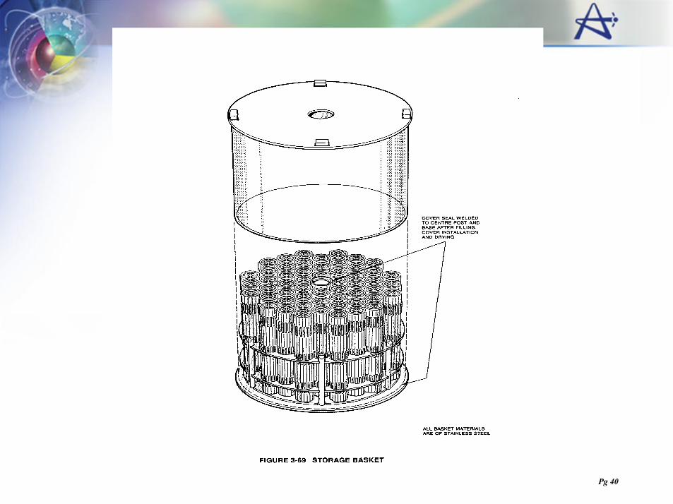
Pg 40

Pg 41
Dry Fuel Storage (MACSTOR)

Pg 42
Dry Fuel Storage
• Fuel transferred to dry storage when decay heat is lowered (approx. 7 W)
• Fuel transferred out of trays in to basket or module assemblies
• These are then moved to concrete containers− Two types of design have been used at CANDU sites:
• vaults with multiple sealed basket (MACSTOR / CANSTOR)• single sealed flask (DSC)

Pg 43
Control Room

Pg 44
Control Room

Pg 45
Fuel Handling Control

Pg 46