on levees - unipi.it · on levees barbara cosanti, ph.d. university of pisa – june 30 th, 2017....
TRANSCRIPT

ON LEVEES
Barbara Cosanti, Ph.D.
University of Pisa – June 30th, 2017
Relevant research activities at the University of Pisa (B. Cosanti; D. Lo Presti ; N. Squeglia)

GEOTECHNICALINVESTIGATIONS
FAILURECAUSES
PREVISION METHODS FOR QUALITY CONTROLS
MONITORING SYSTEMS
DESIGN & CONSTRUCTION
INSPECTION, MAINTENANCE, MONITORING & REMEDIATION
LEVEES
B. Cosanti, Ph.D.

GEOTECHNICALINVESTIGATIONS
Design & Constructions:
B. Cosanti, Ph.D.

Notable extension(levees run for many km)
High level of detail required
DESIGN OF THE GEOTECHNICAL
CAMPAIGN
CRITERIA FOR A COST-EFFECTIVE INVESTIGATION
PLENTIFUL RAINFALL&
SNOW MELTING
Two subsequent flood waves
3 LEVEEFAILURES
Serchio River ● Flood event in 2009(Lucca & Pisa Districts - Northern Tuscany, Italy)
Considerable expertise & flexible budgets
Need for:
B. Cosanti, Ph.D.

TO CLARIFY THE CAUSES OF FAILURE
TO DESIGN APPROPRIATE REPAIR OF THE FAILURES
TWO INVESTIGATION CAMPAIGNSTO DEFINE THE LEVEE SYSTEM
CONDITIONS
TO IDENTIFY THE RISK AREAS
BUDGET PLANNING FOR LEVEE IMPROVEMENT~ 3 km
~ 30 kmB. Cosanti, Ph.D.

GEOTECHNICAL INVESTIGATIONS
15 continuous sampling (4 m depth) carried out using a specially devised micro–stratigraphic sampler(AF shallow core system, Principe et al. 1997) (sample compaction measuring each 50 cm)
4 boreholes (15 m depth)(4 Shelby samples retrieved from each borehole for laboratory testing)
15 CPTu (10 m depth)(for every CPTu 1 or 2 dissipation tests carriedout in the foundation soil).
35 boreholes*For each borehole:- 4 Osterberg samples retrieved for laboratory testing- 2 Casagrande piezometer installations- 4 Lafranc tests
~ 3 km ~ 30 km
CPTu (20 m depth) every 200 m
2D Electric Resistivity Tomography (ERT) every 200 m carried out along cross sections of the embankment
* In the district of Lucca all the boreholes were carried out from the embankment bank because of the limited width of the crest
B. Cosanti, Ph.D.

GEOTECHNICAL MODEL
BOREHOLES
CONTINUOUS SAMPLING
CPTU
B. Cosanti, Ph.D.

NATURAL UNIT WEIGHT [kN/m3]Sandy silt Silty sand Sand
Continuous samples 12.8 12.3 17.7
Shelby samples 19.6 19.1 18.5
NATURAL UNIT WEIGHT
CONTINUOUS SAMPLES
γnSHELBY SAMPLES »
- Following investigation campaign:
- Very loose soils
Very low values but consistent with the results of CPTuindicating DR of about 10%
B. Cosanti, Ph.D.

CPeT-ITGeologismiki
STRATIGRAPHYCMODEL
BOREHOLES
LABORATORYTESTS
CPTU
B. Cosanti, Ph.D.

SOIL GROUPS defined by laboratory grain size distributions
STRATIGRAPHIC MODEL4 SOIL GROUPS based on
laboratory grain size distributions
BOREHOLE-LOGS
% finer than the No.200
sieve
Vs
SOIL GROUP BOREHOLE-LOG SBT LITHOLOGY>60% (clay >10%) Clayey sandy silt Clay
35÷60% (clay <10%) Sand with clayey silt Clayey siltClay and silty clay
10÷35% Silty sand Sandy silt
<10% Sand Sand and silty sand- Gravel and coarse sand -
B. Cosanti, Ph.D.

length of correctly identified soil layerstotal length of layers belonging to that class
CPTUvs
BOREHOLES
⇒ CPTu
Robertson, 1990
economical and expeditious tool
results need to be calibrated against borehole-logs
% of success of CPTu to give the same classification as from borehole-logs
=
B. Cosanti, Ph.D.

CPTUvs
BOREHOLES
“arbitrary” Ic value associated to soil description
B. Cosanti, Ph.D.

CPTUvs
BOREHOLES
After the correction
B. Cosanti, Ph.D.

FAILURECAUSES
Design & Constructions:
B. Cosanti, Ph.D.

MAIN CAUSES OF FAILURE
MECHANICAL FAILURE
INTERNAL EROSION
OVERTOPPING & EXTERNAL EROSION
B. Cosanti, Ph.D.

qt profiles from CPTu carriedout close to the December2009 failure areas wereassumed as reference qt <
MINIMUM & MAXIMUM ENVELOPES OF qt
assumed as reference for the CPTUscarried out along
the whole levee system
BUDGET PLANNING FOR LEVEE
IMPROVEMENT
qt profile that falls in between the MIN & MAX
ENVELOPES ⇒ particularly low soil resistance :
qt profile close to or higher than the
MAX ENVELOPE:
Risky section
Not risky section

Risky areas
B. Cosanti, Ph.D.

CRITICAL CROSS SECTIONS
GEOMETRIC CRITERIA
Mechanical & hydraulic characteristics< B/H
Presence of a high permeability stratumin between two permeable strata
PLAXFLOW & PLAXIS
FLOW CONDITIONS
Transient
Steady state
SLIDE (RocScience)
SEEP/W & SLOPE/W (GEO-SLOPE)
PC STABL 5M (Achilleos, 1988)
Mechanical failure under seepage conditions
ULTIMATE LIMIT
STATES
Safety conditions against potential HEAVE failure (HYD, NTC 2008)
1.3u ≤0.9σv0
MECHANICAL FAILURE
B. Cosanti, Ph.D.

STABILITY ANALYSES
SLOPE/W
SLIDE
PLAXIS
B. Cosanti, Ph.D.

SECTION SAFETY FACTOR
SLIDE PC-STABL SLOPE-W
9 dx LUCCA 0.621 0.76 0.729
13 dx LUCCA 0.677 0.87 0.655
25 dx LUCCA 0.560 0.62 0.640
39 sx LUCCA 0.819 0.89 0.898
51 sx LUCCA 0.676 0.71 0.710
57 sx LUCCA 0.746 0.78 0.798
4 PISA 1.264 1.40 1.318
27 PISA 1.047 1.19 1.132
32 PISA 0.728 0.99 0.760
48 PISA 0.794 1.02 0.828
51 PISA 0.761 1.09 0.763
57 PISA 0.905 0.93 0.906
STABILITY ANALYSES: stationary flow
Unconfined seepage analysis
Bishop simplified methodWater level coincident with theembankment crest on theriverside and with the ground levelon the countryside
Seepage forces are not considered
(water table level indication)
Very similar failure surfaces Comparable safety factors
SECTIONS CANNOT SUSTAIN THE FLOW
FS<1
B. Cosanti, Ph.D.

Partial saturation of the embankment soil mainly contributes to its stability in the
absence of filtration, leading to acceptable safety margins
STABILITY ANALYSES:steady state Vs transient
flowNone of examined “risky sections”
can sustain the flow
10 days are necessary to approach the steady state flow conditions
permanent flow condition is generally too cautious
BUT (probably) it was reached during December 2009 event B. Cosanti, Ph.D.

INTERNAL EROSION
Terzaghi
KezdiKenney & Lau
Suffusion risk and self–filtering properties
BurenkovaUSACE
Isotomina
construction details unknown
limited available data → boreholes carried out from the levee bank (unreachable levee crest: width between 1.2–3 m) ⇒ lack of grain distribution curves from samples retrieved from the embankment body in the Lucca District
INTERNAL STABILITY ASSESSMENT
INTERNAL EROSION RISK
B. Cosanti, Ph.D.

metallic sheet pile diaphragm within the body of the embankment
cross–section geometry of the embankment modified by
adding a berm
Analysed soils do not seem to be particularly prone to internal erosion
phenomena
Limited number of data
No filters
Impossibility to exclude presence of anomalies and heterogeneities within the
embankments
B. Cosanti, Ph.D.

Case history on the effect of overtopping on a trial
embankment in stabilized soil
Quarry waste from a limestone quarry (CP)
CL (USCS)A6 (AASHTO, UNI CNR 10006)k = 1,6∙10-7 cm/sLL=30%; PI=12%wopt=12%; γdmax=20 kN/m3 (Modified Proctor)
OVERTOPPING & EXTERNAL EROSION
stabilised soil used for the repair of the
Serchio River levees
45% calcite
Levee resiliency during overtopping
experimental full scale embankment

CROSS SECTION → h=2.6m; slope=1/2-2.5
PLAN SHAPE → the embankment enclosed a reservoir
TWO TEST SECTIONS:T1 → CPT2 → CP + 2% lime
B. Cosanti, Ph.D.

B. Cosanti, Ph.D.

OVERTOPPING TESTS 6 hours 15 cm or more of sheet-flow overtopping
B. Cosanti, Ph.D.

OVERTOPPING TESTS

MONITORING SYSTEMS
Inspection, Maintenance, Monitoring & Remediation:
B. Cosanti, Ph.D.

installed within the real scale
embankment of a detention basin
MONITORINGSYSTEM
“Bottacci”
to realistically evaluate hydraulic and saturation
conditions
to calibrate stability analyses under unsteady flow
conditions
to assess the effectiveness of possible countermeasure
PLASTIC DIAPHRAGM(dry mechanical mixing)
Seepage throughembankment and foundation soils
B. Cosanti, Ph.D.

CAPACITIVE SENSORS
dielectric permittivity → VWCplastic diaphragm location
MONITORING SYSTEM
instrumented section
Investigation & section location

B. Cosanti, Ph.D.
MONITORINGCAMPAIGN
Observation time: 7/09/2012 – 7/09/2013
daily rainfall datagroundwater levels
water levels in the detention basinVWC
4 open standpipe piezometers
10HS Decagon sensors locatedin positions A, B, C, D
MONITORING SYSTEM

Diaphragm effectiveness
Shallower moisture sensors are especially sensitive to the water infiltration after rainfall
MONITORINGCAMPAIGN
Observation time: 7/09/2012 – 7/09/2013
B. Cosanti, Ph.D.

Location protected by
the diaphragm
MONITORINGCAMPAIGN
Observation time: 7/09/2012 – 7/09/2013
diaphragm effectiveness

On levee monitoring:Embankments of a lamination basin
for the flood risk mitigation
Need for full-scale experiments
in order to highlight the actual behaviour of soilZeevaert (1972)
PLAXIS
● = measurements
FOUNDATION SOIL:very compressible peaty soil
SETTLEMENTS MONITORING FOR FIVE YEARS
The measured settlements werecompared against the results of a 2DFEM analysis and a 1D simplifiedapproach
MAIN GEOTECHNICAL ISSUES: loss of stability induced by the failure of
the foundation soil loss of stability/serviceability because of
(excessive) settlements
FULL-SCALE TRIAL EMBANKMENT

PREVISION METHODS FOR QUALITY CONTROLS
Inspection, Maintenance, Monitoring & Remediation:
B. Cosanti, Ph.D.
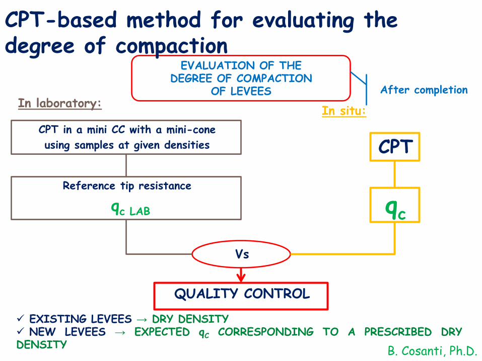
EVALUATION OF THE DEGREE OF COMPACTION
OF LEVEES
qc
CPT in a mini CC with a mini-coneusing samples at given densities
Reference tip resistance
qc LAB
Vs
QUALITY CONTROL
After completion
EXISTING LEVEES → DRY DENSITY NEW LEVEES → EXPECTED qC CORRESPONDING TO A PRESCRIBED DRYDENSITY
CPT-based method for evaluating the degree of compaction
In laboratory: In situ:
CPT
B. Cosanti, Ph.D.

Aluminum mold:Diameter = 320 mm; Height = 210 mm
Top boundary → rigidLateral & bottom boundaries → flexible (provided with latex membranes)
THE EQUIPMENT
Mini-cone: 8 mm diameterLoad cell located above the cone
B. Cosanti, Ph.D.

The compaction effort, required to consolidateeach layer and the whole sample, is recorded:
Samples are reconstituted in 5 layers in astainless steel moldThe soil is prepared at a given w andcompacted to a given γd using static compaction
PARTIALLY SATURATED SILT MIXTURES
TESTED MATERIALS
TICINO SAND
PRELIMINARY CHECK OF THE EQUIPMENT
SILT MIXTURES
USED FOR THE CONSTRUCTION OF NEW LEVEES ANDFOR THE REFURBISHMENT OF EXISTING STRUCTURESSILT
MIXTURES SIEVED TO ELIMINATE THE FRACTION WITH Φ > 2 mm
B. Cosanti, Ph.D.

BARBARA COSANTI, PhD
EXPERIMENTAL PROGRAMFINE-GRAINED
SOILS
DD; PC:γd = 80÷92%γdmax(Modified Proctor)w = wopt
FR:γd = 80%γdmax(Modified Proctor) w= 4; 8; 12%
B. Cosanti, Ph.D.
Boundary conditions:BC1

TEST RESULTS FINE-GRAINED SOILS
B. Cosanti, Ph.D.

TEST RESULTS FINE-GRAINED SOILS
B. Cosanti, Ph.D.

TEST RESULTS FINE-GRAINED SOILS
B. Cosanti, Ph.D.

Water content after sample formation & elapsed time effects
w=wopt=constant over the timeγd=80%γdmax (modified Proctor)
γd=90%γdmax (modified Proctor)
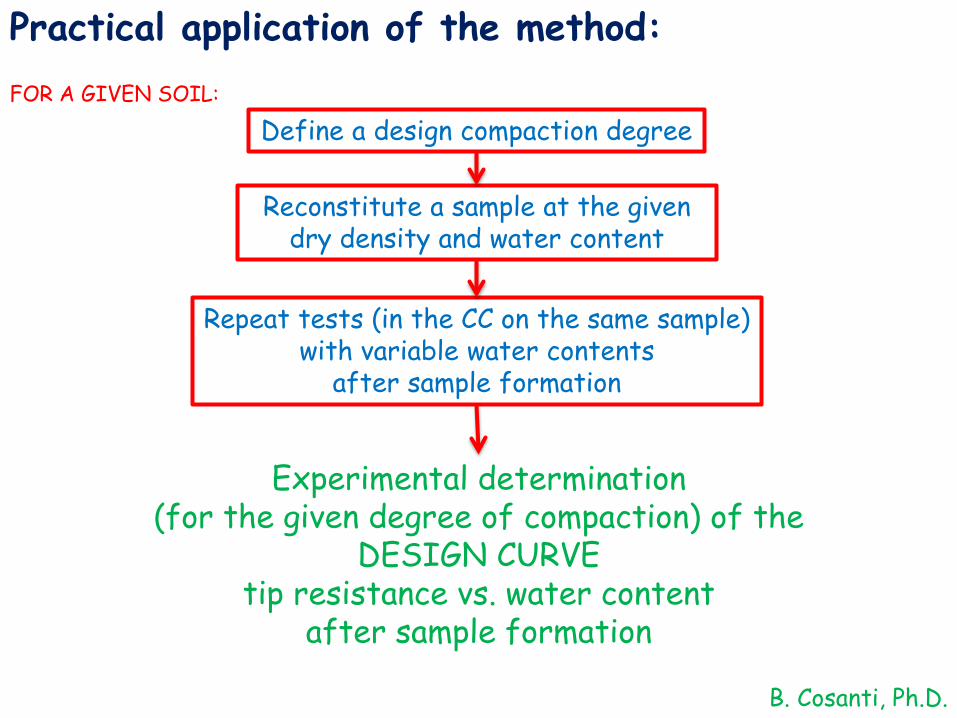
Practical application of the method:
Define a design compaction degree
Reconstitute a sample at the given dry density and water content
Repeat tests (in the CC on the same sample) with variable water contents
after sample formation
FOR A GIVEN SOIL:
Experimental determination (for the given degree of compaction) of the
DESIGN CURVE tip resistance vs. water content
after sample formation
B. Cosanti, Ph.D.

References
1. Cosanti B., Squeglia N., Lo Presti D. C. (2013). “Geotechnical Characterization of the Flood PlainEmbankments of the Serchio River (Tuscany, Italy)”. Conference to Commemorate the Legacy ofRalph B. Peck, 7th International Conference on Case Histories in Geotechnical Engineering andSymposium in Honor of Clyde Baker. Wheeling, IL (CHICAGO, IL AREA). April 29 ‒ May 4, 2013.
2. Squeglia N., Cosanti B., Lo Presti D. C. (2013). “Stability Analysis of the Serchio River FloodPlain Embankments (Tuscany, Italy)”. Conference to Commemorate the Legacy of Ralph B. Peck, 7th
International Conference on Case Histories in Geotechnical Engineering and Symposium in Honor ofClyde Baker. Wheeling, IL (CHICAGO, IL AREA). April 29 ‒ May 4, 2013.
3. Cosanti, B.; Lo Presti, D. C.; Squeglia, N. (2014). “An innovative method to evaluate degree ofcompaction of river embankments using CPT”. CPT14 ‒ 3rd International Symposium on ConePenetration Testing. May 12 – 14, 2014. Las Vegas, Nevada.
4. Cosanti, B.; Lo Presti, D. C., Squeglia, N. (2014). “An Innovative Method to Evaluate Degree ofCompaction of River Embankments.”. XII IAEG Congress. Torino, September 15 – 19, 2014
5. Cosanti, B.; Lo Presti, D. C. (2014). “A monitoring system to study seepage through riverembankments”. XII IAEG Congress. Torino, September 15 – 19, 2014
6. Lo Presti, D.C.; Cosanti, B.; Fontana, T.; Guidi, P. (2014). "Use of plastic diaphragm to improvethe resistance of river embankments against hydraulic failures". XII IAEG Congress. Torino,September 15 – 19, 2014
7. Cosanti B. (2014) – Guidelines for the geotechnical design, upgrading and rehabilitation of riverembankments. PhD Thesis, University of Pisa.
B. Cosanti, Ph.D.

8. Cosanti, B.; Squeglia, N.; Lo Presti, D.C.F. (2014). “Analysis of existing levee systems: theSerchio river case”. RIG. Italian Geotechnical Journal. XLVIII - (4) 2014. AGI. Pàtron EditoreBologna (49-68).
9. Cosanti, B.; Squeglia, N.; Lo Presti, D.C.F. (2016). "A case history on levee external erosion".RIG. Italian Geotechnical Journal. (3), 2016, AGI. Pàtron Editore Bologna (37-44).
10. Squeglia, N.; Cosanti, B.; Lo Presti, D.C.F. (2016). "Importance of full scale tests for thedesign of levees". RIG. Italian Geotechnical Journal. (4), 2016, AGI. Pàtron Editore Bologna(45-56).
11. Lo Presti D., Giusti I., Cosanti B., Squeglia N., Pagani E. (2016). "Interpretation of CPTU in“unusual” soils". RIG. Italian Geotechnical Journal. (4), 2016, AGI. Pàtron Editore Bologna (14-33).
12. Cosanti, B.; Lo Presti, D.C.F.; Squeglia, N. (2016). "Evaluating degree of compaction of leveesusing Cone Penetration Testing". RIG. Italian Geotechnical Journal (under revision).
Thank you for your attention
[email protected]. Cosanti, Ph.D.