on-body flexible printed antennas for body-centric ... for body-centric wireless communications ......
TRANSCRIPT
Loughborough UniversityInstitutional Repository
On-body flexible printedantennas for body-centricwireless communications
This item was submitted to Loughborough University's Institutional Repositoryby the/an author.
Additional Information:
• A Doctoral Thesis. Submitted in partial fulfillment of the requirementsfor the award of Doctor of Philosophy of Loughborough University.
Metadata Record: https://dspace.lboro.ac.uk/2134/6934
Publisher: c© Lei Ma
Please cite the published version.

This item was submitted to Loughborough’s Institutional Repository (https://dspace.lboro.ac.uk/) by the author and is made available under the
following Creative Commons Licence conditions.
For the full text of this licence, please go to: http://creativecommons.org/licenses/by-nc-nd/2.5/

On-body Flexible Printed Antennas for
Body-Centric Wireless Communications
by
Lei Ma
Doctoral Thesis
Submitted in partial fulfillment of the requirements for the award of
Doctor of Philosophy of Loughborough University
2009
© By Lei Ma 2009

Certificate of Originality
This is to certify that I am responsible for the work submitted in this thesis, that the
original work is my own except as specified in acknowledgments or in footnotes, and
that neither the thesis nor the original work contained therein has been submitted to
this or any other institution for a higher degree.
Author's signature …………………………………………………
Date …………………………………

- 1 -
Abstract
This thesis considers wearable antennas that are useful for body-centric
communication systems. Novel wearable printed monopoles with flexible neoprene
substrates and drapable conductive elements have been designed, synthesized and
measured with respect to their on-body performance. Starting with a comprehensive
literature review of wearable antennas this work contains an introduction to wearable
antenna designs, flexible materials for wearable antenna fabrication, human body
models and the impacts of the human body on the efficiency of small wearable
antennas. Definitions of material effective and total conductivity, the calculations of
antenna Q and mutual couplings between antennas and the human body using the
Method of Moment (MoM) are presented. Four types of flexible printed monopoles
have been designed and measured. They are two single band monopoles for ISM
(433.05–434.79 MHz) service, one multiband monopole for GSM 900 (890–960
MHz), DCS (1710–1880 MHz), PCS (1850–1990 MHz), UMTS (1920–2170 MHz),
and WLAN2.4GHz (2400-2484MHz) frequency bands and a UWB band antenna
(3.1-10.6GHz) respectively. Effects of the ground plane dimensions on printed
monopoles are illustrated first by changing the dimensions thereof and subsequently
by adding wing structures. The new designs yield improved impedance match for
printed monopoles. It also shows how meander lines can used to miniaturize antennas
and add additional resonances. Models of the human body were created in
Microstripes, a 3D electromagnetic (EM) simulator, to analysis the impacts of the
human body on the performance of the wearable antennas mentioned above.

- 2 -
To my dearest father, mother, my sister, brother in low, little niece
and my loving girl friend Jing Ma

- 3 -
Acknowledgements
I would like to give my greatest thanks to my supervisor Dr. Rob Edwards, who spent
much time advising and directing me. Thanks for his great enthusiasm and patience
for without his valuable support and encouragement this thesis would not have been
accomplished. He contributed greatly to every paper I have written, and all of the
progress I have made. I learned from him the precise attitude to the research and other
works and benefited from his wide knowledge and creative thoughts. All these will be
huge treasures for my future career and the whole of my life. He has my deepest
respect professionally and personally.
I would also like to thank Dr. William Whittow and Dr. Chinthana Panagamuwa who
shared their experience not only in my research and studies, but also during my time
in Loughborough. Their help and suggestions were very important to my PhD studies.
Mr. Shahid Bashir is my good friend and he contributed to some of my work. Thanks
for his support. Thanks all my fiends in the CMCR lab, Andy, M. I. Khattak, Zubair,
and Arba'íah Inn who have all helped me with my studies. I spent much of my spare
time with my Chinese friends, Yonggang Zhang, Zhi Cao, Zhiwei Zhang, Huanjia
Yang, Yi Qin, Xin Lu and Dawei Liu. We had a fine time in Loughborough. Thanks
for their friendship. Also I would like to thank CMCR, The Department of Electronic
and Electrical Engineering and Loughborough University. Thank you all for giving
me the opportunity to study in such an academic and research centre of excellence.
Finally I would like to thank my family for their patience and encouragement over all
those years we have been separated. Especially thanks go to my dear mother who has
given me all her support and love. She is the force that powers my spirit. I would also
like to thank my wife Jing Ma, who accompanied me in mind during the last four
years of my studies in the UK. Thanks for her great support toward my PhD.

- 4 -
Publications
Ma, L.; Edwards, R. M.; Bashir, S.; Khattak, M. I.; “A wearable flexible
multi-band antenna based on a square slotted printed monopole”, Antennas and
Propagation Conference, 2008. LAPC 2008. Loughborough, 17-18 March 2008
Page(s):345 – 348
Ma, L.; Edwards, R. M.; Whittow, W. G.; “A notched hand wearable ultra
wideband w printed monopole antenna for sporting activities”, Antennas and
Propagation Conference, 2008. LAPC 2008. Loughborough, 17-18 March 2008,
Page(s):397 - 400
Ma, L. Edwards, R.M. Bashir, S. “A wearable monopole antenna for ultra
wideband with notching function”, Wideband and Ultrawideband Systems and
Technologies: Evaluating current Research and Development, 2008 IET Seminar
on, pp. 1-5, Nov. 2008
Ma, L.; Edwards, R. M.; Whittow, W. G.; “A multi-band printed monopole
antenna”, 3rd European Conference on Antennas and Propagation, 2009. EuCAP
2009, 23-27 March 2009, Page(s):962 - 964
Bashir, S.; Hosseini, M.; Edwards, R. M.; Khattak, M. I.; Ma, L.; “Bicep mounted
low profile wearable antenna based on a non-uniform EBG ground plane –
Flexible EBG Inverted-L (FEBGIL) Antenna”, Antennas and Propagation
Conference, 2008. LAPC 2008. Loughborough, 17-18 March 2008, Page(s):333 -
336
Whittow, W. G.; Panagamuwa, C. J.; Edwards, R. M.; Ma, L.; “Indicative SAR
levels due to an active mobile phone in a front trouser pocket in proximity to
common metallic objects”, Antennas and Propagation Conference, 2008. LAPC
2008. Loughborough, 17-18 March 2008, Page(s):149 - 152

- 5 -
Acronyms
AMC Artificial Magnetic Conductor
AMPS Advanced Mobile Phone System
CEM Computational Electromagnetics
CIE Coupled Integral Equations
CPW Coplanar Waveguide
CT Computed Tomography
DCS Digital Communication Systems
EFIE Electric Field Integral Equation
EM Electromagnetic
ETT Electrical Technical Textile
FDTD Finite Difference Time Domain
FEM Finite Element Method
GSM Global System for Mobile communications
HFSS High-Frequency Structure Simulator
HIE Hallén’s Integral Equation
HiperLAN High Performance Radio Local Area Network
ISM Industrial, Scientific and Medical
LSIC Large Scale Integrated Circuit
MoM Method of Moment
MRI Magnetic Resonance Imaging
NMT Nordic Mobile Telephone

- 6 -
PCB Printed Circuit Board
PEC Perfect Electric Conductor
PIFA Planar Inverted F Antenna
SAR Specific Absorption Rate
TACS Total Access Communications System
TLM Transmission Line Matrix
UMTS Universal Mobile Telecommunications System
UWB Ultra-Wide Band
WA Wearable Antenna
WiBro Wireless Broadband
WLAN Wireless Local Area Network

- 7 -
Contents
Abstract……………………………………………………………………………..-1-
Acknowledgements…………………………………………………………………-3-
Publications…………………………………………………………………………-4-
Acronyms……………………………………………………………………………-5-
List of Figures……………………………………………………………………..-10-
List of Tables………………………………………………………………………-17-
List of Variables…………………………………………………………………..-18-
Chapter 1 Literature Review of Wearable Antennas and Human Body................. 1
1.1 Introduction .................................................................................................... 1
1.2 Development of wearable electronics ............................................................ 3
1.3 Wearable antennas and clothing ..................................................................... 4
1.3.1 Antenna selection for wearable applications ..................................... 5
1.3.2 Material selection for wearable antennas ........................................... 7
1.3.3 Human Body Models ......................................................................... 9
1.3.4 Impacts of Human Body on Wearable Antennas ............................. 10
1.4 Summary....................................................................................................... 12
Chapter 2 Analysis of an Antenna close to the Skin ............................................... 21
2.1 Introduction .................................................................................................. 21
2.2 Complex permittivity and equivalent conductivity of medium .................... 22
2.3 Properties of human body tissues ................................................................. 24
2.4 Energy loss in biological tissue .................................................................... 27
2.5 The body’s effects on the Q factor and bandwidth of wearable antennas .... 28
2.6 Couplings between antennas and human body ............................................. 32
2.7 Specific Absorption Rate - SAR ................................................................... 33
Chapter 3 Wearable Printed Monopoles Working for 433MHz ISM Band ......... 38
3.1 Introduction .................................................................................................. 38

- 8 -
3.2 Introduction for Simulation and Measurement Facilities ............................. 40
3.2.1 CST MICROSTRIPES™ EM Simulation Tool ............................... 40
3.2.2 Anechoic Chamber ........................................................................... 40
3.2.3 Wheeler Cap ..................................................................................... 41
3.2.4 Split Post Resonator ......................................................................... 42
3.3 Printed Monopoles on a Finite Ground Plane .............................................. 43
3.4 Flexible materials for wearable antennas ..................................................... 48
3.4.1 Flexible neoprene dielectric substrates for wearable antennas ........ 48
3.4.2 Conductive material selections ........................................................ 49
3.5 Design of wearable straight printed monopoles ........................................... 50
3.5.1 Antenna design ................................................................................. 50
3.5.2 Effects of the human body on the parameters of a printed monopole
.......................................................................................................... 56
3.5.3 Antenna tuning for the printed monopole antenna........................... 62
3.6 Wearable meander printed monopoles ......................................................... 66
3.6.1 Antenna design ................................................................................. 66
3.6.2 Effects of the human body on a printed meander monopole ........... 69
3.6.3 Antenna tuning for a printed meander monopole ............................ 71
3.6.4 The Peak Specific Absorption Rate of an on-body printed meander
monopole .......................................................................................... 76
3.7 Conclusions .................................................................................................. 79
Chapter 4 A Wearable Multi-band Antenna ............................................................ 86
4.1 Introduction .................................................................................................. 86
4.2 A multi-band printed monopole antenna for mobile communication
applications. ............................................................................................... 87
4.2.1 The procedure to design a multi-band printed monopole antenna ... 87
4.3 A wearable multi-band monopole antenna on a neoprene substrate ............ 91
4.3.1 A neoprene version for the wearable multi-band monopole antenna
.......................................................................................................... 91
4.3.2 Antenna efficiency measurement using wheeler cap method .......... 94

- 9 -
4.4 Body Sensitivity of a wearable multi-band printed monopole on the arm. .. 94
4.4.1 Simulated results for body sensitivity of a wearable multi-band
printed monopole on the arm. .......................................................... 94
4.4.2 Measured results for body sensitivity of a wearable multi-band
printed monopole on the arm ........................................................... 97
4.5 The simulated gain and efficiency of a multiband antenna worn on the body.
.................................................................................................................. 103
4.6 Antenna tuning for a multiband printed monopole antenna on a t-shirt arm
.................................................................................................................. 107
4.7 Conclusions ................................................................................................ 116
Chapter 5 A Wearable UWB Antenna with a Notch Band at WLAN5GHz ....... 120
5.1 Introduction ................................................................................................ 120
5.2 Design of a wearable UWB antenna with a notch at WLAN5GHz band... 121
5.3 The human body’s effects on the notched wearable UWB antenna ........... 129
5.4 Tuning for the notched UWB antenna on a glove ...................................... 136
5.5 Conclusions ................................................................................................ 138
Chapter 6 Conclusions and Future Works ............................................................ 142
6.1 Conclusions ................................................................................................ 142
6.2 Future works and considerations ................................................................ 144
Appendix I Radiation Integrals and Auxiliary Potential Functions ................... 147
Appendix II The Method of Moment ..................................................................... 154
II.1 Introduction ................................................................................................. 154
II.2 The Method of Moment (MoM) .................................................................. 155
II.2.1 Pocklington’s Integral Equation ....................................................... 155
II.2.2 Integral Equations and Kirchhoff’s Network Equations .................. 158
II.2.3 Source modeling ............................................................................... 163
Appendix III Hallén’s Integral Equation ............................................................... 165

- 10 -
List of Figures
Figure 1.1 Wearable antennas on Jacket and Shoe ..................................................... 5
Figure 1.2 Loose touches of the felt substrate flexible printed meander monopole .. 8
Figure 1.3 Changes of a microstrip antenna with the movement of our finger ....... 12
Figure 2.1 Dielectric Constant versus frequency for body tissues ........................... 25
Figure 2.2 Loss Tangent versus frequency for body tissues .................................... 25
Figure 2.3 Conductivity versus frequency for body tissues ..................................... 26
Figure 2.4 Antenna with human body aside for Q calculations ............................... 31
Figure 3.1 Efficiency measurement using wheeler cap. ........................................... 41
Figure3.2 Measurement of a piece of neoprene in the 1.925 GHz split post
resonator ................................................................................................. 42
Figure 3.3 Dimensions of the printed monopole and its current distribution at a
certain moment ....................................................................................... 45
Figure 3.4 Simulated return loss of a printed monopole .......................................... 46
Figure 3.5 Simulated radiation patterns for the printed monopole at 475MHz ....... 46
Figure 3.6 Simulated effects of Lground on Return Loss for a printed monopole .. 47
Figure 3.7 Flexible neoprene .................................................................................... 49
Figure3.8 Two 100mm long copper stripes made of traditional (upper) copper
materials and flexible (lower) copper materials ..................................... 50
Figure 3.9 Measured return loss for two ISM433MHz printed monopoles with a
40mm×10mm ground plane and a 2.6mm wide radiating elements (Wm)
................................................................................................................ 51
Figure 3.10 Printed monopole with wings .................................................................. 52
Figure 3.11 Simulated effects of ground plane wings on the input impedance .......... 52
Figure 3.12 The prototype of the wearable straight printed monopole ....................... 53
Figure 3.13 Return Loss for the 192mm straight printed monopole ........................... 54
Figure3.14 Measurement of the return loss for the bent shape of the printed

- 11 -
monopole .................................................................................................. 54
Figure 3.15 Comparison of simulated radiation patterns between .............................. 55
Figure 3.16 Body phantom used to simulate the effects of the thigh on an antenna... 57
Figure 3.17 Comparison of simulated return loss for different thickness ................... 58
Figure 3.18 Simulated antenna gain and efficiency at 433MHz versus the thickness of
the cloth layer ........................................................................................... 58
Figure 3.19 Effects of fatter and thinner phantoms on return loss .............................. 60
Figure 3.20 Measurement of the antenna on thigh ...................................................... 60
Figure 3.21 Measured return loss in six different situations for the antenna on jeans 61
Figure 3.22 Simulated return loss of the tuned straight monopole ............................. 62
Figure 3.23 Simulated antenna gain and efficiency of the tuned straight monopole on
human body versus the thickness of cloth layer .................................... 63
Figure 3.24 Achieved improvements of the antenna gain and efficiency of the tuned
straight monopole ................................................................................... 63
Figure3.25 Simulated radiation patterns of the tuned straight monopole on the
phantom with different thickness of the cloth layer ............................. 65
Figure 3.26 Simulated peak SAR values ..................................................................... 65
Figure 3.27 Measured return loss for the tuned straight monopole on the thigh ........ 66
Figure 3.28 Dimensions of the meander monopole .................................................... 67
Figure 3.29 Prototype of a printed meander monopole ............................................... 68
Figure 3.30 Return loss for the printed meander monopole in free space .................. 68
Figure 3.31 Simulated return loss of the printed meander monopole on the phantom
versus the thickness of the cloth layer ..................................................... 69
Figure 3.32 Comparison of the detuning effects of the body on a printed straight
monopole and a printed meander monopole plotted against the thickness
of the cloth layer .................................................................................... 70
Figure 3.33 Simulated antenna gain and efficiency of the printed meander monopole
on the phantom versus the thickness of cloth layer ............................... 70
Figure 3.34 Return Loss Measurement for a printed meander monopole on the thigh
.................................................................................................................. 72

- 12 -
Figure 3.35 Measured return loss for a printed meander monopole mounted on the
thigh for six common situations ............................................................. 72
Figure 3.36 Dimensions of the tuned meander monopole .......................................... 73
Figure 3.37 Simulated return loss of a printed meander monopole on the body model
after tuning. ............................................................................................ 73
Figure 3.38 Simulated gain and efficiency of a printed meander monopole after
tuning. .................................................................................................... 74
Figure 3.39 Achieved improvements of the antenna gain and efficiency of the tuned
meander monopole ................................................................................. 74
Figure 3.40 Simulated radiation patterns of the meander monopole on human body 76
Figure 3.41 Simulated peak SAR values of a printed meander monopole over a body
insulated by cloth of varied thickness .................................................... 77
Figure3.42 Prototype of the tuned meander monopole for 433MHz on body
applications ............................................................................................ 78
Figure3.43 Measured return loss for a printed meander monopole with varied
common situations ................................................................................. 78
Figure 4.1 The procedure to design a multi-band printed monopole antenna ......... 89
Figure4.2 Comparison of a rectangular monopole and a “winged” rectangular
monopole (Simulated) ............................................................................ 89
Figure 4.3 The prototype of the multi-band monopole antenna built on a FR4 board
................................................................................................................ 90
Figure 4.4 Return losses for the multi-band printed monopole with/without wings 90
Figure 4.5 The prototype of the wearable multi-band monopole antenna ............... 92
Figure 4.6 Measured return loss for the wearable multi-band monopole ................ 92
Figure 4.7 Measured patterns for the wearable multi-band antenna in free space ... 93
Figure 4.8 A three layer arm phantom used to simulate an antenna placed on the
arm. ........................................................................................................ 96
Figure 4.9 Comparison of the simulated return loss for the multi-band antenna on
an arm model with different thicknesses of a cloth layer ...................... 96
Figure 4.10 Cloths used for measurements ................................................................. 98

- 13 -
Figure4.11 Measured return loss on different locations and different cloth with
different situations for the multi-band antenna ...................................... 102
Figure4.12 Simulated antenna gain and efficiency at different frequencies on the arm
phantom versus the thickness of cloth layer .......................................... 105
Figure4.13 Simulated return loss at 900MHz on the arm phantom versus the thickness
of cloth layer .......................................................................................... 106
Figure 4.14 Antenna dimensions and the prototype for a tuned multiband body worn
antenna to be used on the arm of a t-shirt .............................................. 108
Figure 4.15 Simulated and measured return loss for a tuned multiband body worn
antenna in free space ............................................................................ 109
Figure 4.16 Simulated return loss for a tuned multiband body worn antenna on the
arm phantom versus different thickness cloth ...................................... 109
Figure 4.17 Measured return loss for a tuned multiband body worn antenna on the
t-shirt arm with different situations ...................................................... 110
Figure 4.18 Simulated antenna gain and efficiency at different frequencies for the
tuned antenna on the arm phantom ...................................................... 111
Figure 4.19 Improvement of antenna gain and efficiency for the tuned antenna at
different frequencies ............................................................................ 113
Figure 4.20 Simulated peak SAR values for the tuned multi-band antenna at different
frequencies with 10dBm input power .................................................. 114
Figure 4.21 Measured radiation patterns for the tuned multiband body worn antenna
on a 1.4kg pork leg joint at different frequencies ................................ 116
Figure 5.1 A square printed monopole with two symmetrical corners cut off ....... 122
Figure 5.2 Return loss consisting of three resonances for UWB band .................. 122
Figure 5.3 The dimensions and prototype of the notched UWB antenna .............. 123
Figure 5.4 Simulated effects of different dimension slots on the return loss ......... 124
Figure5.5 Comparison of simulated return loss for the wearable notched UWB
antenna with varied substrate conductivity .......................................... 126
Figure5.6 The return loss for the notched UWB antenna in free space ................. 127
Figure5.7 Measured radiation patterns for the notched UWB antenna in free space

- 14 -
.............................................................................................................. 129
Figure 5.8 Two sections of the lossy body model .................................................. 130
Figure5.9 Simulated return loss for the notched UWB antenna on the lossy body
model versus different thickness cloth layer ........................................ 131
Figure5.10 Simulated antenna efficiency and gain for the notched UWB antenna on a
lossy body model at different frequencies ............................................. 132
Figure5.11 A glove and body position for the return loss measurements for the
notched UWB antenna on hand ............................................................. 133
Figure 5.12 Measured return loss for the notched UWB antenna ............................. 133
Figure 5.13 Measured return loss for the notched UWB antenna ............................. 134
Figure5.14 Measured radiation patterns at 4GHz and 6GHz for the notched UWB
antenna on a pork leg joint with 2.5mm felt inserted between .............. 135
Figure 5.15 The dimensions and prototype of the tuned UWB antenna ................... 137
Figure5.16 Simulated return loss for the tuned UWB antenna on the lossy body
model ...................................................................................................... 137
Figure5.17 Measured return loss for the tuned UWB antenna .................................. 138
Figure I.1 The procedure for a computing radiated fields ....................................... 147
Figure II.1 Highly conducting thin wire and its equivalence model along z-axis .... 156
Figure II.2 Theoretical models for a thin wire .......................................................... 157
Figure II.3 Expansion functions ............................................................................... 159
Figure II.4 Point-matching ........................................................................................ 161
Figure II.5 The delta gap source model with impressed field δ/Ai VE = ................. 163

- 15 -
List of Tables
Table 3.1 Measured Permittivity and Loss tangent of different samples at
1.925GHz ……………………………………………………………… 45
Table 4.1 Comparison of antenna efficiency (dB) measured in different methods
………………………………………………………………………….98
Table 4.2 Measured SAR values for the tuned multi-band antenna at different
frequencies with 10dBm input power………………………………...119
Table 5.1 Comparison of antenna efficiency (%) / gain (dBi) with varied substrate
conductivity...........................................................................................130

- 16 -
List of Variables
ε Permittivity
rε Relative Permittivity
aε Permittivity of a Wearable Antenna Consisting of Lossy Materials
Rε Real Part of the Permittivity
aRε Real Part of the Permittivity of a Wearable Antenna Consisting of Lossy
Materials
Iε Imaginary Part of the Permittivity of a Wearable Antenna Consisting of
Lossy Materials
aIε Imaginary Part of the Permittivity of a Wearable Antenna Consisting of
Lossy Materials
eIε Effective Imaginary Part of the Permittivity
µ Permeability
rµ Relative Permeability
H Magnetic Field Intensity
B Magnetic Flux
E Electric Field Intensity
D Electric Displacement Vector
nD Unknown Coefficient of D
ρ Electric Charge Density
J Electric Current Density

- 17 -
totalJ Total Current Density
I e Electric Current Source
M Magnetic Current Density
A Vector Potential
eφ Arbitrary Electric Scalar Potential
cσ Conduction Conductor
pσ Polarization Conductor
eσ Equivalent Conductivity
totalσ Total Conductivity
δtan Loss Tangent
ω Radian Frequency
f Frequency
λ Wavelength
fλ Wavelength at 433 MHz in Free Space
η Impedance of Free Space
hv Volume of the Body Tissue
av Volume of Antennas
)(rv Volume of a Large Sphere Which Surrounds the Antenna
±nV Volume of the Tetrahedron ±
nT
na Area of the thn Face of the Tetrahedron ±nT
±nT Two Conterminous Tetrahedrons
Q Quality Factor

- 18 -
lossW Energy Loss in Biological Tissue
RP Radiated Energy of Antennas
RfP Radiated Energy of Antennas in Free Space
RhP Radiated Energy of Antennas close to Human Body
LP Ohmic Losses of Antennas
LfP Ohmic Losses of Antennas in Free Space
LhP Ohmic Losses of Antennas close to Human Body
SP Reactive Energy Stored Around Antennas
SfP Reactive Energy of Antennas in Free Space
ShP Reactive Energy of Antennas close To Human Body
VFBW Voltage Standing-Wave Ratio bandwidth
)(ωZ Input Impedance of Antennas
( )R ω Input Resistance
)(ωX Input Reactance
R Radius of a Large Sphere Which Surrounds the Antenna
γr
Position Vector Respect to the Original Point
+nρr
Position Vector Respect to Free Vertex of the Tetrahedron
τ Field Point inside the Human Body
'τ Source Point inside the Human Body
)(E γr
Sum of the Incident and Re-Radiating EM Wave
)(γr
mnqP 3D Pulse Function
)(γr
nf Basis Function for Tetrahedral Volume Elements

- 19 -
)',( γγψ Dyadic Green’s Function
Lg Length of the Ground Plane
Wg Width of the Ground Plane
Lm Length of the Monopole
Wm Width of the Monopole
Ls Length of the Substrate
Lw Length of the Wings
Ww Width of the Wings
S11 S Parameter at Port 1

1
Chapter 1
Literature Review of Wearable
Antennas and Human Body
1.1 Introduction
The 1980s saw the beginnings of what has now become a revolution in personal
communication systems. Although there are several contenders, the first viable
voice-only cellular system is thought to have been NMT (Nordic Mobile Telephone)
which was an analogue cellular system deployed in Nordic countries, Eastern Europe
and Russia. Other early starters included TACS (Total Access Communications
System) in the United Kingdom and AMPS (Advanced Mobile Phone System) in the
United States. Early systems tended to have less than convenient handsets with
cumbersome power requirements. Over almost three decades now there has been a
generally increasing demand for handsets that are smaller with increased facility and
longevity of use. This demand has been satisfied by improvements in technology
particularly in the field of miniaturization whereby components of communication
system are generally much reduced in size.
The majority of current personal communication systems are based around wireless
technologies. Typically an antenna is used in such systems to transmute from or into
guided energy in the circuitry of the radio into or from an electromagnetic wave for
the transmission and reception of the energy onto which information is carried.
Antennas have the property that they work best at resonance and their efficiencies are
strongly linked to physical size such that they are often made to be at least half a
wavelength in at least one of their dimensions. This has meant that they are perhaps

Literature Review of Wearable Antennas and Human Body Chapter 1
2
somewhat more resistant to miniaturization than other components of personal
communication systems. A recent trend therefore has been to move the antennas out
of the system and onto the human body where more space is available. We call them
on-body antennas or wearable antennas (WAs).
A good antenna design can decrease the power that the communication systems need
and improve the bit error rate. For wearable applications, they should also be able to
resist the effects from the human body and in addition bring little harm to our health
[1]. Big ground planes are usually preferred for wearable antennas since they can
increase a wearable antenna’ stability and isolate human body from the
electromagnetic (EM) radiation. Such radiofrequency radiation is linked to specific
absorption rate (SAR) which is discussed later in this thesis. However, big ground
planes increase the size and rigidity of wearable antennas. Many antennas are rigid,
which makes them uncomfortable to be embedded into skin or clothing. This has
resulted in a demand for new type antennas better suited to operate in close proximity
to humans. Several types of antennas now have wearable implementations. In
particular these are microstrip antennas, printed dipoles or loop antennas, printed
monopoles or planar inverted F antennas (PIFAs). Such antennas are normally flat and
small and can loosely be described as comprising of four elements, namely, a feed, a
ground plane, a dielectric substrate and one or more radiating elements all of which
have typically been rigid. By replacing the traditional antenna materials with flexible
materials wearable antennas become more comfortable and therefore attractive to
users.
Wearable antennas should also be water-resistant so as to be washable together with
clothing. The property of water resistance in such flexible materials can also prevent
absorbing perspiration which may be salty and therefore conductive.
Literature Review of Wearable Antennas and Human Body Chapter 1
3
1.2 Development of wearable electronics
In general there are currently three types of wearable electronics (WEs). Firstly there
are systems that are worn directly, secondly there are those that are integrated into
clothing (smart clothing), and thirdly there are those that are used as accessories on
the clothing. Of these smart clothing is most common and popular with the military.
Bulky radio equipment may reduce soldiers’ mobility and combat utility, plus
traditional whip or stub antennas are easily targeted by enemies, so invisible,
lightweight and embedded WEs are more popular in present day to secure soldiers’
safety and improve their combat utility[2] [3]. Besides military uses, WEs have been
developed for commercial uses [4] [5]. When compared with hand held devices, WEs
have an advantage since they can help free user’s hands and enable people to carry
more. Multimedia WEs are discussed in [6] and demonstrate this point. In addition
WEs are beginning to provide some unique experiences. An example of this is the
Hug Shirt™ which is a shirt that makes people send hugs over wireless [7]. It does
this by having a set of wireless controlled actuators integrated into a shirt.
When compared to the small space offered by small mobile devices, placement of
WEs on the body offers more available space and therefore more options to help
improve system performance. Multi-input Multi-output (MIMO) system’s channel
capacity [8] is an example of this.
A wrist worn medical monitoring computer was designed to free a high risk patient
from the constraints of a stationary monitoring equipment. This system can
continuously monitor and log the status of the pulse, blood oxygen saturation and
temperature of a patient. Any abnormal trends are then sent via wireless to a hospital
[9]. “An Ultrasound Wearable System for the Monitoring and Acceleration of
Fracture Healing in Long Bones” was proposed by the authors of [10]. [11] also
describes a device that provides support for health telemetry.

Literature Review of Wearable Antennas and Human Body Chapter 1
4
In addition to health care, WEs can realize the functions of many types of
communication and entertainment devices. In early 2000, Philips put their first
wearable electronics garments, ICD+ jackets, on the market. These jackets included
communications (phone) and multimedia entertainment (MP3 player) functions [12].
In 2004, GapKids started selling something called the Hoodio: it was a
machine-washable hooded fleece jacket with an FM-radio control panel sewn onto
one sleeve and removable speakers tucked inside the hood [13]. Besides garments
stated above, bracelets, rings, glasses or other ornaments can also become structures
for integrated WEs [14].
1.3 Wearable antennas and clothing
As in most wireless systems, antennas play a very important role in WEs. A good
antenna design may extend wireless range and reduce power consumption. Therefore
the design of suitable wearable antenna (WA) is important especially because of the
impacts of the human body. In general wearable antennas with very few if any
exceptions have been strongly linked to items of clothing. There have been examples
of WAs on rings [15] and as components in prosthesis [16] but these will not be
considered here. Further, such antennas have tended to appear in clothing that is more
robust. For example antennas in jackets, hats and shoes are far more common than
antennas in socks, shirts or undergarments (see Figure 1.1). Antennas can be affixed to
the surface of or incorporated with the fabric of most common items of clothing [17]
[18]. Typically the further away from the skin an item of clothing is, the less likely it
is to be washed and this fact can make life easier for engineers. However, this is not
the major motive for their placement, as electrical insulation from the body of a
wearer turns out to be a dominant factor in design (This will be shown in later
chapters).

Literature Review of Wearable Antennas and Human Body Chapter 1
5
(a) Bluetooth iJacket [4] (b) Verb for Shoe [19]
Figure 1.1 Wearable antennas on Jacket and Shoe
In view of their importance and practicability, the WAs have been designed to cover a
wide application range. Two WAs, designed for military and police applications at
frequency band 350MHz are presented in [17], [20]. The first was worn on the lumbar
region, and the second was worn on the shoulder; WA designs for GSM900/1800 can
be found in [18], [21] where the antennas were incorporated into the sleeve and on the
back. Hertleer and his colleagues show us their WA designs for 2.45GHz Industrial,
Scientific and Medical (ISM) frequency band in [22], [23]; [24], [25] present designs
for 2.4/5GHz Wireless Local Area Network (WLAN) applications. More recently
wearable Ultra Wideband (UWB) antennas are another focus point for engineers, and
we can find them in [26]-[28]. It should be noted that in most if not all of these papers,
the design methods including tuning and modeling are not the focus.
1.3.1 Antenna selection for wearable applications
For integration into clothing, antennas are usually required to be small, lightweight,
and flexible. They should have stability and exhibit safe to our health when placed
close to the body [29]. There are several candidate antenna types suitable for WAs,
including PIFAs [21], microstrip antennas [22] [24], and planar monopoles [28].
Microstrip antennas are usually preferred among these options. Microstrip antennas

Literature Review of Wearable Antennas and Human Body Chapter 1
6
have some significant advantages for on-body wearables, the three major ones being
their ease of construction, their cost effectiveness and an associated metallic ground
plane that when used between the body and the radiating elements can significantly
reduce the energy absorbed by the body [30]. However, microstrip antennas tend to
have narrow bandwidth and may need to be relatively large if they are to be robust
against perturbation by the body. Another antenna type, the printed monopole antenna,
has a small profile, wide multi-band performance, and omni-directional radiation
patterns. However, since the printed monopoles typically have no ground plane
underneath their radiating elements, they may have relatively stronger coupling to the
body. So far, however, these effects have not been intensively studied.
In [31], a dual band button antenna for WA applications is introduced. This antenna is
a top loaded monopole with a microstrip line feed and is shaped as a button.
Simulations and measurements show this antenna has omni-directional radiation
patterns with a 2.4dB gain at the plane parallel to the human body skin. This is an
attractive characteristic when communicating with other antennas in the same plane in
a body area network. Yet another WA type is the magnetic loop antenna which for
small loops is also referred to as electrically small loop antenna. In [32], the authors
point out that the human body shows low impedance to the electromagnetic wave,
which reduces the electric field close by while increases the magnetic field. Since the
body is rather conductive [33] that along the tangent direction of the body’s surface it
is the magnetic field rather than the electric field that is at a maximum. This means
that theoretically the most efficient antenna on the surface of the body should couple
to the magnetic field rather than the electric field. In general loop type antennas can
do this well. In the past, electrically small loop antennas have been used in on-body
devices such as pager. However, since these loops were small in terms of electrical
size they were also quite inefficient [34].

Literature Review of Wearable Antennas and Human Body Chapter 1
7
1.3.2 Material selection for wearable antennas
Previously most printed monopoles have used rigid materials. However for WAs we
may desire an antenna that conforms to clothing and is therefore soft, lightweight and
comfortable. To retain the nature of clothing, some flexible and comfortable materials
have been used to build WAs, such as fleece fabric [24] and denim [26]. Different
materials may bring significant impacts on WAs. Taking microstrip antennas as an
example, typically for wearable microstrip antennas the substrate materials chosen
have been textiles. Textiles tend to have low relative permittivity (<2) and suffer
somewhat from trapped air which may have variable electrical characteristics due to
water content. Water has a dielectric constant around 80 at 20 °C [35]. So many
textiles show higher dielectric constant when they absorb water. Antennas with such a
substrate usually have a lower resonant frequency and narrow bandwidth [36].
Another problem to some of the textiles is their fluffy or rough surfaces, which result
in a loose contact between substrate and any radiating elements. This may affect the
antennas’ stability from one build to another increasing the need for tuning.
Furthermore simulations for fuzzy electrical and magnetic boundaries are more
complex to model and evaluation of their performance may therefore suffer. Figure
1.2 shows a small (70mm × 40mm × 4mm) WA. This particular antenna is a flexible
printed meander monopole antenna with a felt substrate. Note how the fuzzy nature of
the felt and its less than perfect planar properties cause its extent and the extent of the
radiating elements to be less precise than the case for a traditional printed version.

Literature Review of Wearable Antennas and Human Body Chapter 1
8
Figure 1.2 Loose touches of the felt substrate flexible printed meander monopole
The materials of the conductive parts of wearable microstrip antennas are important to
the antenna’s performance. To make the conductive parts of an antenna more
comfortable to human body, the technique of interweaving copper threads and
non-conductive fabric is commonly used instead of traditional copper tapes [37]. It is
found that this interweaving will reduce the antenna efficiency compared to the
microstrip antenna made of pure copper. In addition, facing the more conductive sides
(with more copper threads) of the radiation part and ground plane together will give
better performance than other cases. In [38], the authors tested six WLAN2.4GHz
antennas with different copper patterns for the conductive parts. They concluded that
at 2.4GHz the conductive fabric must be densely knitted and use sufficient conductive
materials, and the discontinuous of conductivity in the direction of the current flow
should be avoided.
In [39], different electronic textiles were manufactured and tested using commercially
available materials and traditional textile manufacturing methods. In [40], fabrics with
copper fibers in one or both directions and with different yarn fineness for signal
transmission are presented. These materials have given us more options to find out the
Literature Review of Wearable Antennas and Human Body Chapter 1
9
most suitable materials for wearable antenna designs.
1.3.3 Human Body Models
In the design of WAs it is important to take account of the interaction between the
antenna and the human body. All the commonly used antenna parameters, such as
resonant frequency, bandwidth, radiation pattern, and particularly efficiency are likely
to change radically as an antenna moves close to the body and therefore a free space
design may only be a crude estimate of antenna suitability. To better understand these
effects, researchers have created body models or so called phantoms. These models
can be grouped into computational and physical types. Most computational models
are based on detailed human body parameters and consist of a matrix mapped to space
with each element containing details about conductivity, permeability and permittivity.
One popular digital image dataset of complete human male and female cadavers in
MRI, CT and anatomical modes is The Visible Human Project® [41]. Some
computational human body models based on it have been created and tested [42] [43].
Sometime these detailed human body models need large computation resource, so one
may use only part of the body or create a simple 3D model in commercial simulation
software such as CST, Microstripes, and HFSS. Computational human body models
have been widely used in evaluating the mobile phone’s effects on different parts of
human body, mainly the specific absorption rate (SAR) in the head [44] [45]. In
addition these models are also available to use for the study of the effects between
WAs and the human body. Other example models are provided by organizations such
as [46] [47]. |Care must be taken in choosing a model since different permittivity
mapping will bring different results for characteristics such as SAR values [48] [49].
Physical human body phantoms are the second most popular tool used in testing WAs.
They can be made to represent a real person, an animal, a solid phantom or
tissue-equivalent dielectric liquid. Experiments with live humans may provide results
Literature Review of Wearable Antennas and Human Body Chapter 1
10
for WAs such as return loss and/or radiation patterns. However, some experiments,
particularly where knowledge of the fields inside the body are sought are impossible
to obtain from live people and thus animals (not commonly) and vessels filled with
tissue simulating liquids are often used [50] [51].
1.3.4 Impacts of Human Body on Wearable Antennas
The body may have significant impacts on WAs close by. Study of these impacts can
help us better understand the design of WAs.
The tissues of the human body have relatively high dielectric constants [46] [47]. The
consequence of this is that inside the body the EM waves are shorter than those in free
space. In free space the voltage between the terminals of an antenna generates current
flow on the antennas’ conductive elements. Here we define current as the flow of
electrical charge carriers (electrons). Accelerating electrons give rise to propagating
electromagnetic waves around the antenna the density of which can be described by
lines of flux. The flux lines are densest close to the antenna in a region known as the
near field. The intermediate field and far field are composed of flux lines
progressively less dense and farther away from the antenna. As an antenna is moved
closer to a human body, more of the flux lines produced by the currents on the antenna
occur inside biological tissue and are thereby compressed. Due to this, antennas near
to the human body become electrically larger than when just in free space and
therefore resonate at lower frequencies and are detuned. Some antennas on the skin
are shorted out since the skin is conductive. This means that current cannot flow
easily in their intended routes on the antennas and this disturbs the antennas’ ability to
generate flux lines. With these changes, the antennas’ working frequency and the
quality of any supported wireless link may be lower.
A second important impact of biological tissue is that it absorbs energy that might

Literature Review of Wearable Antennas and Human Body Chapter 1
11
usefully be radiated. For example the far field radiation pattern of a UWB antenna
held close to the head will show a null on the side of the antenna where the head is
situated [52]. This increasing loss due to absorption by the body is most clearly seen
as decreasing antenna efficiency.
The third and related effects are demonstrated in [53] where researchers investigated
the performance of wearable antennas in different on-body locations. They suggested
that to reduce the effects of the body, an antenna with ground plane is preferred. Note
that the dielectric properties are not symmetrical in any plane which effectively means
that the effect of the body for example an antenna placed right side of the chest will be
different from that of the same antenna placed at a mirrored spot on the left side of the
chest. For on-body communication links, different locations mean different body
channel characteristics. In [54] and [55], the authors simulated and measured the
performance of different antennas with different on-body locations to test the
characteristics of body channels. Their results showed that not just the relative
positions of the transmitting and receiving antennas but also the antenna types have
significant effects on the body channels. It turned out that monopole - monopole
combination gave the lowest link loss in all the measured relative positions for
on-body communication. In addition, their studies have been performed on the impact
of human body postures and results suggest that different postures have significant
effects on the performance of WAs [56].
Besides those mentioned above, distortion of guided Electromagnetic waves within
the volume of the WA itself is an additional factor for consideration in design. WAs
are usually made of soft and flexible materials and are therefore designed to be
conformal. Their shape will change with the movement of our joints or the fold of
clothing, and the associated EM guided wave paths will also be changed as a result.
To illustrate the point, considering a conformal WA designed to fit upon the finger of a
glove.

Literature Review of Wearable Antennas and Human Body Chapter 1
12
(a) Straight finger and corresponding (b) Bent finger and
E fields between patch and ground plane corresponding E fields
. Figure 1.3 Changes of a microstrip antenna with the movement of our finger
The sketch in Figure 1.3 shows a representation of a flexible microstrip antenna. We
assume that the guided wave supported by currents on the radiating elements and
ground plane of the antenna oscillates in a plane parallel to the page width. The upper
diagrams show how the antenna is distorted as the finger’s movement. The lower
diagrams show how the electric field may change from having a linearly distributed
electric field density in the plane of propagation to that of a logarithmic field
distribution in the plane of propagation. Results related to this are written up in [22],
[57], and from these works we see that the bending of the WA may lead to detuning.
1.4 Summary
In this chapter, we have reviewed recent literature on WAs. Particularly, WAs that can
be integrated into garment were introduced and discussed. This chapter has also
introduced factors relating to antenna selection, material selection, human body
models, absorption of energy, biological tissue and the impacts of human body on the
electrical characteristics of WAs.
The majority of the papers referred to so far in this thesis have been concerned with

Literature Review of Wearable Antennas and Human Body Chapter 1
13
planar antennas that have a ground plane, for example PIFAs [21]. This is reasonable
since these antennas have some significant advantages for on-body wearables, the
three major ones being their ease of construction, their cost effectiveness and an
associated metallic ground plane that when used between the body and the radiating
elements can significantly reduce the proportion of flux produced by the antenna
occurring in the lossy tissue of the body. However, these antenna types also tend to
have narrow bandwidth and may need to have a large ground plane if they are to be
robust against perturbation by the body, and this factor may be contrary to the
requirements that future electronic devices require of antennas such as low visibility,
miniaturization and large-scale integration. Therefore a printed monopole may have
better performance: wider bandwidth, be generally smaller in size and produce better
omni-directional radiation patterns than current popular types of antennas in the
literature. Therefore the work presented in this thesis details the results related to
experimental designs for wearable printed monopole antennas worn on and close to
the body.

Literature Review of Wearable Antennas and Human Body Chapter 1
14
References
[1] N. Noury, P. Barralon, D. Flammarion, “Preliminary Results on the Study of
Smart Wearable Antennas,” Engineering in Medicine and Biology Society, 2005.
IEEE-EMBS 2005. 27th Annual International Conference of the, pp. 3814-3817,
2005.
[2] https://wearableantenna.com/tactical_vest_antenna_system/ (Cited on Jan. 5 2008)
[3] http://www.pharad.com/wearable.html (Cited on Jan. 5 2008)
[4] http://www.gizmag.com/go/7856/ (Cited on Jan. 5 2008)
[5] http://www.nec.co.jp/press/en/0710/3101.html (Cited on Jan. 5 2008)
[6] http://www.gizmag.com/go/6789/ (Cited on Jan. 5 2008)
[7] http://www.cutecircuit.com/products/wearables/thehugshirt/ (Cited on Jan. 5
2008)
[8] Yuehui Ouyang Love, D.J. Chappell, W.J., “Body-Worn Distributed MIMO
System”, Vehicular Technology, IEEE Transactions on, Volume: 58, pp. 1752 -
1765 ,May 2009
[9] Lukowicz, P.; Anliker, U.; Ward, J.; Troster, G.; Hirt, E.; Neufelt, C.; “AMON: a
wearable medical computer for high risk patients”, Sixth International Symposium on
Wearable Computers, 2002. (ISWC2002). Proceedings, Page(s):133 – 134, 7-10 Oct.
2002
[10] Protopappas, V.C.; Baga, D.A.; Fotiadis, D.I.; Likas, A.C.; Papachristos, A.A.;
Malizos, K.N.; “An Ultrasound Wearable System for the Monitoring and Acceleration
of Fracture Healing in Long Bones”, IEEE Transactions on Biomedical Engineering,
Volume 52, Issue 9, Page(s):1597 – 1608, Sept. 2005
[11] Noury, N.; Dittmar, A.; Corroy, C.; Baghai, R.; Weber, J.L.; Blanc, D.; Klefstat,
F.; Blinovska, A.; Vaysse, S.; Comet, B.; “VTAMN - A Smart Clothe for Ambulatory
Remote Monitoring of Physiological Parameters and Activity”, Conference
Literature Review of Wearable Antennas and Human Body Chapter 1
15
Proceedings of 26th Annual International Conference of the Engineering in Medicine
and Biology Society, 2004, EMBC 2004. Volume 2, 2004 Page(s):3266 – 3269
[12]http://www.design.philips.com/about/design/portfolio/researchprojects/wearableel
ectronics/index.page (Cited on Jan. 5 2008)
[13]http://gizmodo.com/gadgets/notag/gap-hoodio-jacket-with-built+in-radio-25466.p
hp (Cited on Jan. 5 2008)
[14] http://www.gizmag.com/ibangle-wearable-design-concept/10263/ (Cited on Jan.
5 2008)
[15] H. H. Asada, P. Shaltis, A. Reisner,Sokwoo Rhee,R. C. Hutchinson,"Mobile
monitoring with wearable photoplethysmographic biosensors," Engineering in
Medicine and Biology Magazine, IEEE, vol. 22, pp. 28-40, 2003.
[16] K. Gosalia, G. Lazzi, M. Humayun,"Investigation of a microwave data telemetry
link for a retinal prosthesis," Microwave Theory and Techniques, IEEE Transactions
on, vol. 52, pp. 1925-1933, 2004.
[17] K. Ogawa, T. Uwano, M. Takahashi,"A shoulder-mounted planar antenna for
mobile radio applications,” Vehicular Technology, IEEE Transactions on, vol. 49, pp.
1041-1044, 2000.
[18] P. J. Massey, "GSM fabric antenna for mobile phones integrated within
clothing,” Antennas and Propagation Society International Symposium, 2001. IEEE,
vol. 3, pp. 452-455 vol.3, 2001.
[19] http://www.gizmag.com/go/3565/ (Cited on Jan. 8 2008)
[20] A. Christ, W. Kainz, Ji Chen,Yogendra Shah,N. Kuster,"Current and Future
Needs for the Simulation of Small and Implanted Antennas for Medical
Applications," Antenna Technology Small Antennas and Novel Metamaterials, 2006
IEEE International Workshop on, pp. 148-151, 2006.

Literature Review of Wearable Antennas and Human Body Chapter 1
16
[21] P. Salonen, L. Sydanheimo, M. Keskilammi, M. Kivikoski,"A small planar
inverted-F antenna for wearable applications," Wearable Computers, 1999. Digest of
Papers. the Third International Symposium on, pp. 95-100, 1999.
[22] C. Hertleer, A. Tronquo, H. Rogier,L. Vallozzi,L. Van Langenhove,
"Aperture-Coupled Patch Antenna for Integration Into Wearable Textile Systems,"
Antennas and Wireless Propagation Letters, IEEE, vol. 6, pp. 392-395, 2007.
[23] C. Hertleer, H. Rogier, L. Van langenhove,"Design of textile antennas for smart
clothing," Proceedings of the 7th UGent PhD Symposium, 29/11/2006, Ghent,
Belgium, 2006.
[24] P. Salonen, L. Hurme, "A novel fabric WLAN antenna for wearable
applications,” Antennas and Propagation Society International Symposium, 2003.
IEEE, vol. 2, pp. 700-703 vol.2, 2003.
[25] B. Sanz-Izquierdo, F. Huang, J. C. Batchelor,M. Sobhy,"Compact Antenna for
WLAN on body applications," Microwave Conference, 2006. 36th European, pp.
815-818, 2006.
[26] B. Sanz-Izquierdo, J. C. Batchelor, M. I. Sobhy,"Compact UWB Wearable
Antenna,” Antennas and Propagation Conference, 2007. LAPC 2007. Loughborough,
pp. 121-124, 2007.
[27] M. Klemm, G. Troester, "Textile UWB Antennas for Wireless Body Area
Networks,” Antennas and Propagation, IEEE Transactions on, vol. 54, pp. 3192-3197,
2006.
[28] Taeyoung Yang, W. A. Davis, W. L. Stutzman,"Wearable ultra-wideband
half-disk antennas,” Antennas and Propagation Society International Symposium,
2005 IEEE, vol. 3A, pp. 500-503 vol. 3A, 2005.
[29] GuCnel P., Raskmark P., and Anderson J. B. and Lynge E., “Incidence of cancer
in persons with occupational exposure to electromagnetic fields”, Brit. J. Ind., Med.
50, page(s): 758-764., 1992

Literature Review of Wearable Antennas and Human Body Chapter 1
17
[30] Ramesh Garg, Prakash Bhartia, Inder Bahl,Apisak Ittipiboon,"Microstrip antenna
design handbook," Artech House Antennas and Propagation Library, November
2000.
[31] B. Sanz-Izquierdo, F. Huang, J. C. Batchelor,"Dual Band Button Antennas for
Wearable Applications,” Antenna Technology Small Antennas and Novel
Metamaterials, 2006 IEEE International Workshop on, pp. 132-135, 2006.
[32] K. Fujimoto, J. R. James, "Mobile Antenna Systems Handbook, 1st edition,"
Artech House, 1994.
[33] S Gabriel, R W Lau and C Gabriel, “The dielectric properties of biological
tissues: II. Measurements in the frequency range 10 Hz to 20 GHz”, al 1996 Phys.
Med. Biol. 41, pp2251-2269
[34] Constantine A. Balanis; “Antenna Theory Analysis and Design”, the second
edition, chapter 5, 1998
[35] M.uematsu, E. U. Franck, “Static Dielectric Constant of Water and Steam”, J.
Phys. Chem. Ref. Data, Vol.9 No.4, 1980
[36] P. Salonen, Y. Rahmat-Samii, M. Schaffrath,M. Kivikoski,"Effect of textile
materials on wearable antenna performance: a case study of GPS antennas,"
Antennas and Propagation Society International Symposium, 2004. IEEE, vol. 1, pp.
459-462 Vol.1, 2004.
[37] Yuehui Ouyang, E. Karayianni, W. J. Chappell,"Effect of fabric patterns on
electrotextile patch antennas," Antennas and Propagation Society International
Symposium, 2005 IEEE, vol. 2B, pp. 246-249 vol. 2B, 2005.
[38] P. Salonen, Y. Rahmat-Samii, H. Hurme,M. Kivikoski,"Effect of conductive
material on wearable antenna performance: a case study of WLAN antennas,"
Antennas and Propagation Society International Symposium, 2004. IEEE, vol. 1, pp.
455-458 Vol.1, 2004.
[39] C. A. Winterhalter, J. Teverovsky, P. Wilson,J. Slade,W. Horowitz,
"Development of electronic textiles to support networks, communications, and

Literature Review of Wearable Antennas and Human Body Chapter 1
18
medical applications in future U.S. Military protective clothing systems,"
Information Technology in Biomedicine, IEEE Transactions on, vol. 9, pp. 402-406,
2005.
[40] T. Kirstein, C. Cottet, J. Grzyb,G. Tröster,"Textiles for signal transmission in
wearables," Proceedings of the Workshop on Modeling, Analysis and Middleware
Support for Electronic Textiles (MAMSET), San Jose, CA, 6 October 2002.
[41] http://www.nlm.nih.gov/research/visible/visible_human.html (Cited on Jan. 10
2008)
[42] L. Catarinucci, P. Palazzari, L. Tarricone,"On the use of numerical phantoms in
the study of the human-antenna interaction problem,” Antennas and Wireless
Propagation Letters, IEEE, vol. 2, pp. 43-45, 2003.
[43] L. Catarinucci, P. Palazzari, L. Tarricone,"A parallel FDTD tool for the solution
of large dosimetric problems:" Microwave Symposium Digest, 2002 IEEE MTT-S
International, vol. 3, pp. 1755-1758, 2002.
[44] L. Shoshiashvili, A. Razmadze, N. Gritsenko,R. Zaridze,"Averaged SAR
distributions and temperature rise estimatton in child head model with 835MHZ
handset phone," Direct and Inverse Problems of Electromagnetic and Acoustic Wave
Theory, Proceedings of Xth International Seminar/Workshop on, pp. 168-171, 2005.
[45] S. -. Watanabe, H. Taki, T. Nojima,O. Fujiwara,"Characteristics of the SAR
distributions in a head exposed to electromagnetic fields radiated by a hand-held
portable radio," Microwave Theory and Techniques, IEEE Transactions on, vol. 44,
pp. 1874-1883, 1996.
[46] http://niremf.ifac.cnr.it/tissprop/htmlclie/htmlclie.htm#atsftag (Cited on Jan. 11
2008)
[47] http://www.fcc.gov/fcc-bin/dielec.sh (Cited on Jan. 11 2008)

Literature Review of Wearable Antennas and Human Body Chapter 1
19
[48] W. D. Hurt, J. M. Ziriax, P. A. Mason,"Variability in EMF permittivity values:
implications for SAR calculations,” Biomedical Engineering, IEEE Transactions on,
vol. 47, pp. 396-401, 2000.
[49] P. Gajsek, W. D. Hurt, J. M. Ziriax,P. A. Mason,"Parametric dependence of SAR
on permittivity values in a man model," Biomedical Engineering, IEEE Transactions
on, vol. 48, pp. 1169-1177, 2001.
[50] J. C. Lin, "Effects of microwave and mobile-telephone exposure on memory
processes,” Antennas and Propagation Magazine, IEEE, vol. 42, pp. 118-120, 2000.
[51] W. Whittow, C. J. Panagamuwa, R. Edwards,J. C. Vardaxoglou,"Specific
Absorption Rates in the Human Head Due to Circular Metallic Earrings at
1800MHZ," Antennas and Propagation Conference, 2007. LAPC 2007.
Loughborough, pp. 277-280, 2007.
[52] Zhi Ning Chen Ailian Cai See, T.S.P. Chia, M.Y.W. , “Small planar UWB
antennas in proximity of human head”, Ultra-Wideband, 2005. ICU 2005. 2005
IEEE International Conference on, pp. 4, 5-8 Sept. 2005
[53] A. Alomainy, Y. Hao, D. M. Davenport,"Parametric Study of Wearable Antennas
with Varying Distances from the Body and Different On-Body Positions,” Antennas
and Propagation for Body-Centric Wireless Communications, 2007 IET Seminar on,
pp. 84-89, 2007.
[54] A. Alomainy, Yang Hao, C. Parini,P. Hall,"Characterisation of printed UWB
antennas for on-body communications," Wideband and Multi-Band Antennas and
Arrays, 2005. IEE (Ref. no. 2005/11059), pp. 53-57, 2005.
[55] M. R. Kamarudin, Y. I. Nechayev, P. S. Hall,"Performance of antennas in the
on-body environment,” Antennas and Propagation Society International Symposium,
2005 IEEE, vol. 3A, pp. 475-478 vol. 3A, 2005.
[56] A. Alomainy, A. S. Owadally, Y. Hao,C. G. Parini,Y. I. Nechayev, C. C.
Constantinou and P. S. Hall,"Body-Centric WLANs for Future Wearable Computers,"

Literature Review of Wearable Antennas and Human Body Chapter 1
20
International Workshop on Wearable and Implantable Body Sensor Network,
Imperial College London, April, 2004.
[57] Peter S. Hall, Yang Hao, "Antennas and Propagation for Body-Centric Wireless
Communications,” Artech House, 2006.
21
Chapter 2
Analysis of an Antenna close to the Skin
2.1 Introduction
The purpose of this chapter is to introduce the properties of human body tissues and
their effects on an antenna’s Q factor and bandwidth. An example analysis will be
shown that uses the Method of Moment (MoM) in the modeling of biological tissue
that allows the computation of the coupling effects between antennas and human
bodies.
It turns out that small antennas interact strongly with human tissues [1] [2]. In fact at
all of the popular frequencies used for mobile communications a typical un-optimized
free space antenna would see all of its important parameters, for example directivity,
radiation pattern, input impedance and efficiency, markedly changed in the proximity
of biological tissue. This is mainly because the body consists of elements that have
different electrical properties and is therefore inhomogeneous and thus dispersive. S.
Gabriely, R. W. Lau and C. Gabriel from King’s College have measured the dielectric
properties of human body tissues. They did this by adapting a 50 ohm conical probe to
interface with the target tissues. Then using an automatic swept-frequency network
and impedance analysers, the authors obtained results which can be used to calculate
the properties of human body tissue from 10Hz to 20GHz. More details can be found
in [3]. Their work proves that the electrical properties of human body tissues are
significantly different from those of free space. The result of this is that EM waves
behave differently in free space from in human body. For example the muscle in an
arm has a dielectric constant of 53.55; the skin in an arm has the dielectric constant of
38.87, and the air that surrounds them has a dielectric constant of 1. At 1.8GHz the
effective wavelength goes from 166.67mm in air to 26.73mm in the skin to 22.78mm
in muscle. The body is also conductive which effectively means that an antenna on the

Analysis of an Antenna close to the Skin Chapter 2
22
skin may be shorted out preventing the current getting to those radiating parts in
sufficient magnitude to allow the antenna to perform well. The study of these
interactions contributes to improved design and safety of WAs. Note that since there is
no tissue with magnetic properties in the body, discussion and analysis in this thesis
assume non-magnetic materials with relative permeability set to unity ( 1rµ = ).
2.2 Complex permittivity and equivalent conductivity of medium
The permeability and permittivity of free space are 0µ = 1.257e-6 H/m and 0ε =
8.85e-12F/m respectively. Assuming non-magnetic materials, the media through
which electromagnetic waves pass have the same permeability as free space but
different permittivity. For most materials permittivity ε is usually a complex value
which consists of a real part Rε and an imaginary part Iε [4].
ε = Rε Ijε− (2-1)
Rε in equation (2-1) reflects the ability of bound charges in a material to polarize in
response to a varying electric field. Higher values mean stronger polarization.
However, since these bound charges are limited in motion by other properties of the
media, there is always a delay before their polarization follows the time varying
electric field. To conquer the motion limitation some of the EM wave energy will be
consumed which leads to the power loss by the material. This is more obvious at high
frequencies where the polarization rate of some bound charges cannot follow the
frequencies such that the value of Rε may in fact decrease with the increased
frequency [5]. The time delay between the time varying electric field and the
polarization rate can be represented in terms of Iε which is a function of frequency
and can be used to compute the consumed power.

Analysis of an Antenna close to the Skin Chapter 2
23
According to time-harmonic form of Maxwell’s equations (see also Appendix I), in
free space with no source,
∇ × H = ωj D = ωj 0ε E (2-1)
Where H is the Magnetic field intensity, ω is the radian frequency, D is the Electric
displacement vector and E is the Electric field intensity.
While in other medium [6],
∇ × H = J + ωj D
= cσ E + ωj ε E
= cσ E + ωj ( Rε j− Iε ) E
= ( cσ +ω Iε ) E + ωj Rε E
= ( cσ + pσ ) E + ωj Rε E
= eσ E + ωj Rε E (2-2)
where J is the current density, cσ and pσ are defined as conduction conductivity and
polarization conductivity respectively and are responsible for the conduction current
and polarization delay. Since cσ and ω Iε have similar effect that leads to the
power loss they can be combined as eσ which is their sum and is called the
equivalent conductivity. Alternatively we may let
cc εωσ= (2-3)
so the effective imaginary part of the permittivity is
Analysis of an Antenna close to the Skin Chapter 2
24
eIε = Iε + cε (2-4)
A second form of equation (2-2) can be derived as follows
∇ × H = eσ E + ωj Rε E
= [ eσ E + ( ωj Rε E ωj− 0ε E)] + ωj 0ε E
= totalσ E + ωj 0ε E
= totalJ + ωj 0ε E (2-6)
By comparing equation (2-2) with (2-6) it can be seen that totalJ comprises all of
the media’s effects on the electromagnetic wave, and that totalσ , which is a complex
value, is related to the conduction and polarization currents.
2.3 Properties of human body tissues
In line with the discussion in 2.2 and given the data it would now be possible to plot
the properties of human tissue as they change with frequency. Using the data from [5]
the next three figures show how the dielectric constant rε ( 0εε
ε Rr = ), loss tangent
δtan (R
I
εε
δ =tan ) and the conductivity vary with the frequency for Blood,
BoneCortical, Fat, Muscle, Nerve and DrySkin.

Analysis of an Antenna close to the Skin Chapter 2
25
0
10
20
30
40
50
60
70
80
90
0 1 2 3 4 5 6 7 8 9 10 11 12Frequency (GHz)
Dielectric Constant
Blood
BoneCortical
Fat
Muscle
Nerve
DrySkin
Figure 2.1 Dielectric Constant versus frequency for body tissues [5]
0
0.5
1
1.5
2
2.5
3
3.5
0 1 2 3 4 5 6 7 8 9 10 11 12Frequency (GHz)
Loss Tangent
Blood
BoneCortical
Fat
Muscle
Nerve
DrySkin
Figure 2.2 Loss Tangent versus frequency for body tissues [5]

Analysis of an Antenna close to the Skin Chapter 2
26
0
2
4
6
8
10
12
14
16
18
0 1 2 3 4 5 6 7 8 9 10 11 12Frequency (GHz)
Conductivity (S/m)
Blood
BoneCortical
Fat
Muscle
Nerve
DrySkin
Figure 2.3 Conductivity versus frequency for body tissues [5]
In general it can be seen that the body’s tissues have dielectric constant values greater
than that of free space. Below 7GHz the dielectric constants of the blood, muscle and
skin are even more than 50 times greater than that of free space while the fat is found
having closer values to free space at all the frequencies. All these values are found
decreasing versus the frequency. The values of loss tangent can be divided into two
sections. In the first section below 1GHz the loss tangent decreases sharply to below
0.5 while above 1GHz, most of the materials have a relative constant value with a
little increasing. In the figure above it can be seen that the conductivity of Dryskin
(skin exposed to air), lies between approximately 1.75 Siemens per meter at 3GHz
and 7 Siemens per meter at 10GHz whilst for blood the conductivity across the same
range of frequencies varies from approximately 3 to 13 Siemens per meter.
We know thatε associated with the permeabilityµ and the frequency f will decide
the wavelength λ of an EM wave in a medium:

Analysis of an Antenna close to the Skin Chapter 2
27
µελ
f
1= (2-5)
So with a fixed frequency, the wavelength of the EM wave will be shorter in the
human body than in free space. A consequence of this is that an antenna designed for
free space applications will be electrically bigger in biological tissue than in air. In
addition since the human body is conductive, when it is exposed to the antenna’s EM
fields there will be a current introduced inside it, which leads to an EM energy loss in
it and also inversely influences the current distribution on the antenna.
2.4 Energy loss in biological tissue
In Equation (2-2) we were able to combine cσ and pσ into the effective
conductivity eσ . Using this parameter along with knowledge of the electric field, the
energy loss in biological tissue lossW can be defined as
(2-6)
where hv is the volume of tissue to be integrated. In essence energy from the EM
waves becomes heat in the tissue and therefore constitutes a loss. Since the closer to
the WA the greater the electric field density is, when moving the WA closer to the
body the greater proportion of loss in the tissue is generated. Reducing such losses
can be achieved in several ways and these are discussed at length in subsequent
chapters. However all of these methods conclude to ways to reduce the electric field
density in biological tissue.
∫=hv
he dvE2
loss σW

Analysis of an Antenna close to the Skin Chapter 2
28
2.5 The body’s effects on the Q factor and bandwidth of wearable
antennas
The Quality Factor Q is an important parameter of antennas. It relates the radiated
energy RP and ohmic losses LP of an antenna to the reactive energy SP stored
around the antenna’s structure.
(2-7)
All these parameters are functions of angular frequency ω . Here we assume
01j t
te ω
== and suppress it. In [7], the Q factor was related to the voltage
standing-wave ratio bandwidth ( VFBW ) using the following equalities.
)('
)(2)(Q ω
ωω
ω ZR
≈ (2-8)
where
)()()( ωωω jXRZ += (2-9)
is the input impedance of the antenna and
ωω
ωω
ωωωd
dXj
d
dRjXRZ
)()()(')(')(' +=+= (2-10)
is the frequency derivative of the complex input impedance. Real part ( )R ω is the
input resistance and imaginary part )(ωX is the input reactance.
)(
)(4)(FBW
'Vωω
ωβω
Z
R≈ (2-11)
so
)()(
)()(
ωωωω
ωLR
S
PP
PQ
+=

Analysis of an Antenna close to the Skin Chapter 2
29
)(FBW
2)(Q
V ωβ
ω ≈ (2-12)
where β is subject to the defined bandwidth and can be referred to formula (34) in
[7]. We can see from (2-12) that Q factor is approximately inversely proportional to
the defined bandwidth.
The human body can be thought of as a lossy medium that has its greatest effect when
closest to a wearable antenna. We can calculate its effects on the Q of an antenna
using the methods described in [7] and [8]. If we assume a WA consisting of lossy
materials with permittivity aIaRa jεεε −= to be non-magnetic (permeability is 0µ ) we
can state that
( ) ( )[ ]
[ ]
[ ]
+−+
Ω−+=
Ω−+=
∫
∫ ∫
∫ ∫
−∞→
∞→
a
a
v
aIaR
vrvr
rv
''
rSf
dvHEj
dFrdvHE
dFrdvHEP
2
0
2
)( 4
2
0
2
0
2
0
)( 4
2
0
22
)'()'(4
1
),(2lim4
1
),(2lim4
1
µωεωε
φθεµε
φθεωµωε
π
π
(2-13)
[ ] Ω=⋅×= ∫∫ ∗ dFdSnHEPs
Rf
2
4
),(2
1ˆRe
2
1
π
φθη
(2-14)
∫=av
aILf dvEP2
2ε
ω (2-15)
where SfP , RfP and LfP are the reactive energy, radiated energy and ohmic losses of
the antenna in free space respectively. r is the radius of a large sphere which surrounds
the antenna. It is assumed the radiated energy will travel infinitely far so r is set to ∞ ,
and

Analysis of an Antenna close to the Skin Chapter 2
30
φθθ ddrdSd sin/ 2 ==Ω (2-16)
and ( )φθ ,F is the far electric field pattern
( ) E(r)reF jkr
r ∞→= lim, φθ (2-17)
η is the impedance of free space, )(rv is the volume including the antenna and
surrounding space and av is the volume of the antenna. So the Q factor can be
obtained by
LfRf
Sf
fPP
PQ
+=
ω (2-18)
While when a WA works close to human body (see Figure 2.4) which has a complex
permittivity )()()( ωεωεωε eIR j−= , a constant permeability 0µ , and the volume hv ,
we can get
(2-19)
Ω∫=⋅∫
∗×= dFdSn
s
HEPRh
2
4
),(2
1ˆRe
2
1
πφθ
η (2-20)
∫+∫=
h
e
a
aILh
v
dvE
v
dvEP22
2σε
ω (2-21)
( ) ( )[ ]
[ ]
[ ]
[ ]
+−+
+−+
Ω−+=
Ω−+=
∫
∫
∫ ∫
∫ ∫
−−∞→
∞→
h
a
ha
v
eIR
v
aIaR
vvrvr
rv
''
rSh
dvHEj
dvHEj
dFrdvHE
dFrdvHEP
2
0
2
2
0
2
)( 4
2
0
2
0
2
0
)( 4
2
0
22
)'()'(4
1
)'()'(4
1
),(2lim4
1
),(2lim4
1
µωεωε
µωεωε
φθεµε
φθεωµωε
π
π

Analysis of an Antenna close to the Skin Chapter 2
31
Figure 2.4. Antenna with human body aside for Q calculations
where ShP , RhP and LhP are the reactive energy, radiated energy and ohmic losses of
the antenna close to human body respectively. The Q factor of the WA is
LhRh
Shh
PP
PQ
+=
ω (2-22)
From (2-19) and (2-21) we can find that human body close to WAs has the similar
effects on the Q factor as the antenna’s own lossy materials. A lossy material has the
function to increase the antenna’s bandwidth [9]. If we assume the same power has
been delivered to the WA, with the decrease of the distance between the antenna and
human body, more reactive energy and radiation energy will be consumed as heat by
human body, so we can predict SfSh PP < and RfRh PP < . Since LhP comes from both
the reduction of SfP and RfP , it leads to >+ LhRh PP LfRf PP + . So a lower Q factor
could be achieved when a WA works close to human body. Due to the inverse
relationship between Q factor and bandwidth, we may conclude that a WA close to
human body will have wider bandwidth than in free space.

Analysis of an Antenna close to the Skin Chapter 2
32
2.6 Couplings between antennas and human body
From Appendix I and II we know that the unknown current on the wire antenna
working in free space can be written as Pocklington’s Integral Equation or Hallen’s
Integral Equation and solved by MoM. When this antenna works close to the body,
another current is excited in that body due to the EM fields generated by the antenna.
The excited current acts as a scatter, generating fields that may adversely affect the
antenna’s original current distribution. An analytical solution for this situation is
available via Coupled Integral Equations (CIE) [10]. There are two equations included
in CIE, respectively named the Electric Field Integral Equation (EFIE) for the induced
electric field inside the human body and the Hallen’s-type Integral Equation (HIE, see
also in Appendix III) for the antenna current distribution with mutual coupling terms.
[ ] [ ]∫∫ −⋅=⋅−
+ 2
20
')',(ˆ)'(I)',()(E()(E3
1l
l
v
totaltotal dzzzzdvPV
jh
τψττψτστωεσ
(2-23)
zkVjduuzkuj
zkBzkAdzzzKzI
z
l
l
000
0
002
2
sin2
)(sin)(4
sincos')',()'(
∫
∫
−=−+
++−
ηπ
ηπ b
zE
(2-24)
where totalσ can be found in formula (2-6), PV denotes the principal value of the
integral, τ and 'τ are the field and source point inside the human body, z and 'z are
the field and source point along the antenna surface respectively, A and B are
unknown constants and 0V is the driving-point input voltage. )(zb
zE is the
component of the scattered electric field from the body at the antenna surface
[ ]dvzPVz
hv
e
b
z ∫ ⋅= )',()(E)(E τψτσ (2-25)
and )',( γγψ is the dyadic Green’s function

Analysis of an Antenna close to the Skin Chapter 2
33
)',(I)',( 02
0
0 ττψωµττψ
∇∇+=
kj (2-26)
where
'4)',(
'
0
0
ττπττψ
ττ
−=
−− jke
(2-27)
And 000 µεω=k , )exp()',( 0RjkzzK −= , 22)'( azzR +−=
The unknown antenna’s current )'(zI and the electric field )(E τ in human body in
equations (2-23) and (2-24) can be solved using MoM by dividing the wire antenna
into N segments and human body into M cubic cells, totally (N+3M)× (N+3M)
equations (antenna along zr
direction and human body along xr
, yr
, zr
directions).
When we obtain the current on the antenna and the E fields in the human body, we
can deduce all other antenna’s parameters such as efficiency, radiation pattern and
input impedance (See Appendix I). Due to the power consumption in the human body,
the WA’s efficiency will decrease compared with in free space, and the radiation
pattern becomes more directive.
2.7 Specific Absorption Rate - SAR
Previous sections have been focused on the possible impacts of the human body on
the antennas, while in practice the evaluation of the risks that the antennas’ EM fields
may bring to the human body is also important. The best known effect of EM fields
on the human body is to cause dielectric heating, for example the findings of the
temperature increase in eyes due to absorbed radio frequency (RF) energy are shown
in publications [11] and [12]. Another concern is that radio frequency radiation can

Analysis of an Antenna close to the Skin Chapter 2
34
trigger cancer. For example in [13], a risk for breast cancer was suggested for men
who were heavily exposed to EM fields, and an increased risk for leukemia was found
for the electricians who were exposed to EM fields.
Specific Absorption Rate (SAR) is used to quantify the absorbed EM energy by the
human body. SAR is defined as
ρ
σ2E
SAR = (2-28)
where σ and ρ are the conductivity and density of the human body tissues
respectively and E is the electric field in the tissues. SAR is measured in watts
per kilogram (W/kg). In the United States, the Federal Communications
Commission (FCC) requires a SAR level at or below 1.6watts per kilogram
(1.6W/kg) averaged over 1 gram of tissue (SAR 1g) in head [14], while the
council of the Europe Union sets the limit at or below 2W/kg over 10 gram of
tissue (SAR 10g) in head [15]. Some other organizations also released their
standards of SAR limits [16]. Note that different parts of human body are
permitted to have different SAR limits. For instance SAR values in limbs are
usually permitted to be higher than in head [16].
For antennas with a ground plane between the radiating element and the human body,
the dimensions and shapes of the ground plane are found to have significantly effects
on SAR values [17],[18]. To get a lower SAR value, usually a bigger ground plane is
needed, but at the same time this leads to a bigger antenna size. Frequency
electromagnetic bandgap (EBG) materials are widely used to miniaturize antenna size,
enhance gain values and suppress surface wave propagation [19] [20]. Recently they
are also used to reduce WAs’ SAR values [21] [22].

Analysis of an Antenna close to the Skin Chapter 2
35
References
[1] Zhi Ning Chen Ailian Cai See, T.S.P. Chia, M.Y.W. , “Small planar UWB
antennas in proximity of human head”, Ultra-Wideband, 2005. ICU 2005. 2005 IEEE
International Conference on, pp. 4, 5-8 Sept. 2005
[2] Byndas, A.; Kucharski, A.; Kabacik, P.; “Experimental study of the interactions
between terminal antennas and operators”, Antennas and Propagation Society
International Symposium, 2001. IEEE, Volume 3, Page(s):74 - 77, 8-13 July 2001
[3] S Gabriel, R W Lau and C Gabriel, “The dielectric properties of biological tissues:
II. Measurements in the frequency range 10 Hz to 20 GHz”, Phys. Med. Biol. 41, 1996,
pp. 2251-2269
[4] C Gabriel, S Gabriely and E Corthout, “The dielectric properties of biological
tissues: I. Literature Survey”, Phys. Med. Biol. 41, 1996, pp. 2251-2269
[5] http://niremf.ifac.cnr.it/tissprop/htmlclie/htmlclie.htm#atsftag (Cited on Jan. 30
2008)
[6] Sarwate, V. V., “Electromagnetic fields and waves”, New York ; Chichester : John
Wiley, c1993
[7] A. D. Yaghjian, S. R. Best, "Impedance, bandwidth, and Q of antennas," Antennas
and Propagation, IEEE Transactions on, vol. 53, pp. 1298-1324, 2005.
[8] A. D. Yaghjian, "Improved Formulas for the Q of Antennas with Highly Lossy
Dispersive Materials," Antennas and Wireless Propagation Letters, IEEE, vol. 5, pp.
365-369, 2006.
[9] K. H. Pan, J. T. Bernhard, T. G. Moore,” Effects of lossy dielectric material on
microstrip antennas," Antennas and Propagation for Wireless Communications, 2000
IEEE-APS Conference on, pp. 39-42, 2000.

Analysis of an Antenna close to the Skin Chapter 2
36
[10] H. -. Chuang, "Numerical computation of fat layer effects on microwave
near-field radiation to the abdomen of a full-scale human body model," Microwave
Theory and Techniques, IEEE Transactions on, vol. 45, pp. 118-125, 1997.
[11] Bernardi, P.; Cavagnaro, M.; Pisa, S.; Piuzzi, E.; “SAR distribution and
temperature increase in an anatomical model of the human eye exposed to the field
radiated by the user antenna in a wireless LAN”, Microwave Theory and Techniques,
IEEE Transactions on, Volume 46, Issue 12, Part 1, Dec. 1998 Page(s):2074 -
2082
[12] Buccella, C.; De Santis, V.; Feliziani, M.; “Prediction of Temperature Increase in
Human Eyes Due to RF Sources”, Electromagnetic Compatibility, IEEE Transactions
on, Volume 49, Issue 4, Nov. 2007, Page(s):825 - 833
[13] GuCnel P., Raskmark P., and Anderson J. B. and Lynge E., “Incidence of cancer
in persons with occupational exposure to electromagnetic fields”, Brit. J. Ind., Med.
50, 1992, page(s): 758-764
[14] http://www.fcc.gov/cgb/sar/ (Cited on Feb. 4, 2008)
[15] The Council Of The European Union, “COUNCIL RECOMMENDATION of 12
July 1999 on the limitation of exposure of the general public to electromagnetic fields
(0 Hz to 300 GHz)”, Official Journal of the European Communities, 30. 7. 1999
[16] International Commission on Non-Ionizing Radiation Protection, “Guidelines for
Limiting Exposure to Time-Varying Electric, Magnetic, and Electromagnetic Fields
(UP TO 300 GHz)”, ICNIRP Guidelines, 1998
[17] K. ll. Chan, L.C. Fung , S.W. Leung, Y.M. Siu, “Effect of internal patch antenna
ground plane on SAR,” Electromagnetic Compatibility, pp.513 – 516,27 Feb. March
2006
[l8] Arkko, A.T. Lehtola, E.A., “Simulated impedance bandwidths, gains, radiation

Analysis of an Antenna close to the Skin Chapter 2
37
patterns and SAR values of a helical and a PIFA antenna on top of different ground
planes”, Antennas and Propagation, 2001. Eleventh International Conference on (IEE
Conf. Publ. No. 480), vol.2, page(s): 651 – 654, 2001
[19] Fallah-Rad, M.; Shafai, L.; “Enhanced Performance of a Microstrip Patch
Antenna using a High Impedance EBG Structure”, Antennas and Propagation Society
International Symposium, IEEE, vol.3, Page(s): 982 – 985, 2003
[20] Goussetis, G.; Feresidis, A.P.; Palikaras, G.K.; Kitra, M.; Vardaxoglou, J.C.;,
“Flexible metallodielectric electromagnetic bandgap surfaces for improved handset
antenna performance”, Antennas and Propagation Society International Symposium,
IEEE, vol. 2A, Page(s): 590 – 593, 2005
[21] Salonen, P.; Fan Yang; Rahmat-Samii, Y.; Kivikoski, M.; “WEBGA - wearable
electromagnetic band-gap antenna”, Antennas and Propagation Society International
Symposium, IEEE, Vol.1, Page(s): 451 – 454, 2004
[22] Zhu, S.; Langley, R.; “Dual-band wearable antennas over EBG substrate”,
Electronics Letters, Page(s): 141 – 142, 2007
38
Chapter 3
Wearable Printed Monopoles Working
for 433MHz ISM Band
3.1 Introduction
Printed monopoles have been widely used in various applications due to their
attractive features [1] - [3]. Wideband and nearly omni-directional radiation patterns
can be seen in various designs [4] [5]. In [6], the authors presented a printed
monopole with up to 24:1 impedance bandwidth. An omni-directional pattern is often
an industry requirement for antennas used in mobile phones, base stations, and
personal communication devices [7] - [9]. Since these types of antennas may be
formed of microstrip and printed radiation parts onto a PCB, their size and low cost
make them suitable for large scale integration and mass production.
Together with this, there has been a growing interest in wearable electronics and
computer systems or so called “smart clothing” in which radios and computers made
of flexible circuits are embedded into garments [10] [11]. As an important part of the
smart clothing, WAs integrated into clothing are widely used in many areas (see
section 1.2 and 1.3). For WAs integrated into clothing microstrip antennas have been
preferred among the candidates. However, microstrip antennas tend to be of narrow
bandwidth and, when a shielding ground plane is added for stability, may need to be
relatively large if they are to be robust against perturbation by the body.
In the limit a printed antenna with no ground plane will couple most with the body. In
the printed monopole no ground plane exists to isolate the radiating elements from the
human body. Therefore, to study the mutual coupling between them and the body,

Wearable Printed Monopoles Working for 433MHz ISM Band Chapter 3
39
several wearable printed monopoles were designed and are written up in this chapter.
The goals were to first indentify and quantify the effects due to the body and then to
illustrate effective methods for the tuning of antennas on the body with the start point
being a free space model of a particular antenna.
Initially the effects between the human body and low frequency band printed
monopoles which work for 433MHz ISM (Industrial, Scientific and Medical) band
were considered. ISM band is a part of the radio spectrum that can be used by
anybody without a license in most countries. It consists of several separate frequency
bands including 315MHz, 433MHz, 868MHz, 915MHz, 2.4GHz and 5GHz. More
specifically the 433MHz band has been the spectrum choice for many WAs for
medical applications. As an example the bandwidth 433.05MHz to 434.79 MHz has
been used in smart suit with sensors and electronics for monitoring patients at
hydrotherapy sessions in swimming-pools [12]. Microsystems for wireless sensor
networks which can be used to diagnose cardiopulmonary disease have used this band
to transmit biometric data [13].
In this chapter two different types of wearable printed monopoles for the ISM
433MHz band are introduced and compared. These include a straight printed
monopole and a meander printed monopole. Both antennas were first designed and
measured in free space. Subsequently these antennas were measured on the body.
According to the results obtained from a prototype, antennas were then optimized for
integration into clothing. Before giving all the details about the antenna designs and
measurements, the simulation and measurement tools used will be introduced.

Wearable Printed Monopoles Working for 433MHz ISM Band Chapter 3
40
3.2 Introduction for Simulation and Measurement Facilities
3.2.1 CST MICROSTRIPES™ EM Simulation Tool
The simulation software used in this thesis was Flomerics MICROSTRIPES™ V7.5
which now is named CST MICROSTRIPES™. MICROSTRIPES™ is based on a
multi-grid formulation of the time-domain Transmission-Line Matrix (TLM) method.
In 1971, Johns and Beurle introduced a novel numerical technique for solving
two-dimensional scattering problems which was based on Huygens’s model of wave
propagation [14]. This method employed a Cartesian mesh of open two-wire
transmission lines to simulate tow-dimensional propagation of delta function impulse.
Subsequent papers by Johns and Akhtarzad extended this method to three-dimensional
problems and included the effects of dielectric loading and losses [15] [16]. This
method is called TLM.
In MICROSTRIPES, users design antennas (or other devices), excitations and
environments in the “Build” window and assign them materials. The “Materials
Library” in MICROSTRIPES provides properties of many commonly seen materials,
including human body tissues. Phaseless human body models can be quickly created
in MICROSTRIPES. At start dielectric material is automatically divided into meshes
modeled as the intersection of orthogonal transmission lines dependant on the
operating frequency and the materials assigned. Smaller meshes allow better
discretization of curved surfaces but also increase simulation time.
3.2.2 Anechoic Chamber [17]
Anechoic chambers are commonly used to measure the far field performance of
antennas. The chamber used in this research was a metal screened room lined with
pyramidal absorbers. The metal prevents most of the radio energy from outside
entering the room. The absorber absorbs energy and breaks up the electromagnetic

Wearable Printed Monopoles Working for 433MHz ISM Band Chapter 3
41
wavefronts thereby greatly reducing the levels of any standing waves. The noise floor
of the chamber used in this work is approximately -60dB. Antennas under test are
placed on the middle line on the long axis of the chamber.
The chamber used for the results in this thesis was a rectangular chamber with
dimensions 3m x 3m x 7m. The measuring instrument was an HP 8753D VNA with a
frequency range from 30KHz to 6GHz supported by a bespoke controller and a two
axis positioner.
3.2.3 Wheeler Cap
Efficiency measured in the chamber can also be checked by way of a Wheeler cap in
which the antenna is measured in and out of a small metal enclosure [18] [19].
Wheeler cap is an accurate and simple way to measure the efficiency of antennas. By
measuring the s-parameter fS11 of the antenna in free space and wS11 in wheeler
cap, we can get the efficiency of the antenna using equation [20]:
)s11)(1s11(1
)s11)(1s11(11Efficiency
wf
wf
−+
+−−= (III-1)
Two shapes of wheeler caps, the half sphere and the cylinder, are commonly used. The
radius of the wheeler cap is usually set to πλ 2/f where fλ is the free space
wavelength of the frequency of interest. Several wheeler caps were constructed to
measure the antenna sets discussed in this research. Considering the length of the
printed monopoles, the cylindrical wheeler cap was used for their measurements. In
Figure 3.1 a wheeler cap made of copper with radius 110mm and used to measure the
efficiency of a printed monopole at 900MHz is shown.

Wearable Printed Monopoles Working for 433MHz ISM Band Chapter 3
42
(a) (b)
Figure 3.1 Efficiency measurement using wheeler cap
3.2.4 Split Post Resonator
Figure 3.2 Measurement of a piece of neoprene in the 1.925 GHz split post resonator
Figure 3.2 shows a split post resonator which is used to measure the permittivity and
conductivity of substrate materials. Split post resonators consist of a metal cavity
inside which are two dielectric resonators. The complex permittivity can be obtained
by inserting the material into the cavity and calculating the frequency perturbation
including the resonant frequency shifts and Q factor changes [21] [22]. Figure 3.2
shows the measurement of a piece of Neoprene (more details about Neoprene are
written up in Section 3.4.1). For this particular batch of neoprene, the measured

Wearable Printed Monopoles Working for 433MHz ISM Band Chapter 3
43
results were relative permittivity 5.2 with loss tangent of 0.03. Both values are only
valid at 1.925GHz which is the centre frequency for a split post resonator of these
dimensions. However values at other frequencies can be reliably inferred as
permittivity tends to decrease and loss tends to increase with frequency. (See section
2.2). Some other materials were also measured and the values are shown in Table 3.1.
As can be seen they are in good agreement with the published values.
Material Permittivity Loss tangent
Polystyrene foam 1.02 0.00009
FR4 4.6 0.025
Felt 1.4 0.03
Cotton 1.54 0.058
Silk 1.2 0.054
Neoprene 5.2 0.03
Table 3.1 Measured Permittivity and Loss tangent of different samples at 1.925GHz
3.3 Printed Monopoles on a Finite Ground Plane
Printed monopoles are a member of the monopole antenna family. A thin wire
perpendicular to a PEC sheet (ground plane) constitutes a basic monopole antenna.
However with printed monopoles all of the radiating components of printed
monopoles are parallel to the ground plane. This has expanded the applications of
monopole antennas, for example integrating with Large Scale Integrated Circuit
(LSIC) or replacing the PCB with a flexible material so as to be suitable for wearable
applications. However in common with thin wire monopoles [23] - [25], the ground
plane size of the printed monopole will alter the antennas’ parameters. The effects of
the ground plane size on printed monopoles can be assessed from the next series of
simulations.
The antenna in Figure 3.3 is a printed monopole. At start a simulation was used to
provide a width for the strip that would equal to a microstrip line with a 50ohm
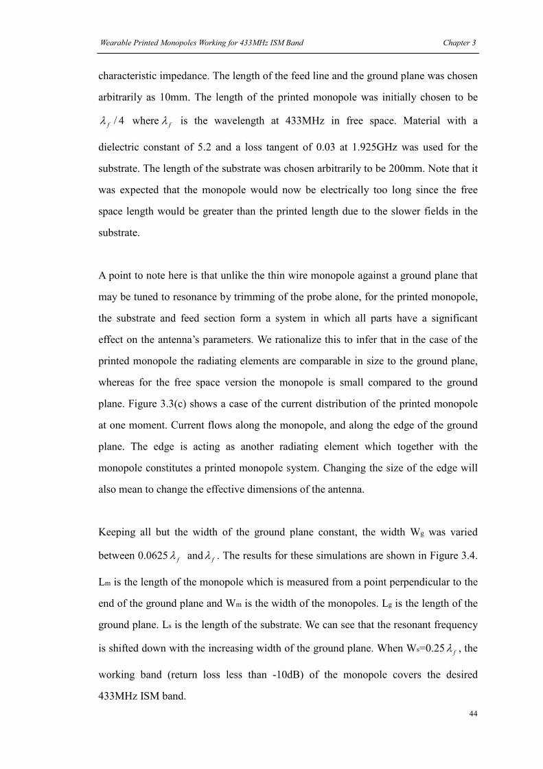
Wearable Printed Monopoles Working for 433MHz ISM Band Chapter 3
44
characteristic impedance. The length of the feed line and the ground plane was chosen
arbitrarily as 10mm. The length of the printed monopole was initially chosen to be
4/fλ where fλ is the wavelength at 433MHz in free space. Material with a
dielectric constant of 5.2 and a loss tangent of 0.03 at 1.925GHz was used for the
substrate. The length of the substrate was chosen arbitrarily to be 200mm. Note that it
was expected that the monopole would now be electrically too long since the free
space length would be greater than the printed length due to the slower fields in the
substrate.
A point to note here is that unlike the thin wire monopole against a ground plane that
may be tuned to resonance by trimming of the probe alone, for the printed monopole,
the substrate and feed section form a system in which all parts have a significant
effect on the antenna’s parameters. We rationalize this to infer that in the case of the
printed monopole the radiating elements are comparable in size to the ground plane,
whereas for the free space version the monopole is small compared to the ground
plane. Figure 3.3(c) shows a case of the current distribution of the printed monopole
at one moment. Current flows along the monopole, and along the edge of the ground
plane. The edge is acting as another radiating element which together with the
monopole constitutes a printed monopole system. Changing the size of the edge will
also mean to change the effective dimensions of the antenna.
Keeping all but the width of the ground plane constant, the width Wg was varied
between 0.0625 fλ and fλ . The results for these simulations are shown in Figure 3.4.
Lm is the length of the monopole which is measured from a point perpendicular to the
end of the ground plane and Wm is the width of the monopoles. Lg is the length of the
ground plane. Ls is the length of the substrate. We can see that the resonant frequency
is shifted down with the increasing width of the ground plane. When Ws=0.25 fλ , the
working band (return loss less than -10dB) of the monopole covers the desired
433MHz ISM band.
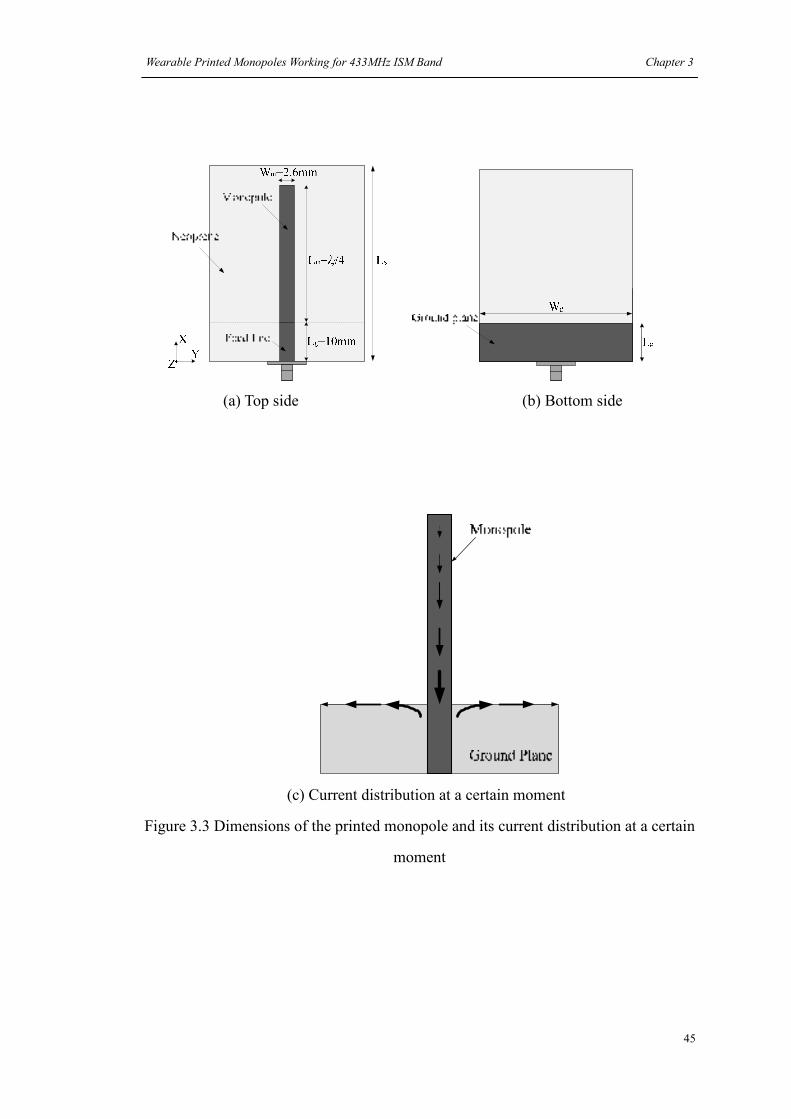
Wearable Printed Monopoles Working for 433MHz ISM Band Chapter 3
45
(a) Top side (b) Bottom side
(c) Current distribution at a certain moment
Figure 3.3 Dimensions of the printed monopole and its current distribution at a certain
moment

Wearable Printed Monopoles Working for 433MHz ISM Band Chapter 3
46
-25
-20
-15
-10
-5
0
100 200 300 400 500 600 700
Frequency (MHz)
Return Loss (dB)
0.0625
0.125
0.25
0.375
0.5
0.625
0.75
0.875
1
Figure 3.4 Simulated return loss of a printed monopole
with various ground plane widths Wg (in fλ )
Referring once more to Figure 3.3 we can see that the printed monopole lies in the XY
plane. In Figure 3.5 the simulated radiation patterns in XZ and YZ planes are shown
for the printed monopole with the best response. Due to the low cross-polar
components, only the co-polar parts are shown here. The resonant frequency for this
system is 475MHz. The patterns show this printed monopole has a typical free space
dipole response, omni-directional radiation patterns.
XZ Plane
-50
-40
-30
-20
-10
00°
45°
90°
135°
180°(-180°)
-135°
-90°
-45°
Co-Polar
YZ Plane
-50
-40
-30
-20
-10
00°
45°
90°
135°
180°(-180°)
-135°
-90°
-45°
Co-Polar
Figure3.5 Simulated radiation patterns for the printed monopole at 475MHz
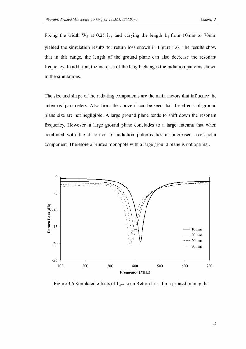
Wearable Printed Monopoles Working for 433MHz ISM Band Chapter 3
47
Fixing the width Wg at 0.25 fλ , and varying the length Lg from 10mm to 70mm
yielded the simulation results for return loss shown in Figure 3.6. The results show
that in this range, the length of the ground plane can also decrease the resonant
frequency. In addition, the increase of the length changes the radiation patterns shown
in the simulations.
The size and shape of the radiating components are the main factors that influence the
antennas’ parameters. Also from the above it can be seen that the effects of ground
plane size are not negligible. A large ground plane tends to shift down the resonant
frequency. However, a large ground plane concludes to a large antenna that when
combined with the distortion of radiation patterns has an increased cross-polar
component. Therefore a printed monopole with a large ground plane is not optimal.
-25
-20
-15
-10
-5
0
100 200 300 400 500 600 700
Frequency (MHz)
Return Loss (dB)
10mm
30mm
50mm
70mm
Figure 3.6 Simulated effects of Lground on Return Loss for a printed monopole

Wearable Printed Monopoles Working for 433MHz ISM Band Chapter 3
48
3.4 Flexible materials for wearable antennas
3.4.1 Flexible neoprene dielectric substrates for wearable antennas
Although there are some notable exceptions, for example body amour, clothing worn
by humans is generally flexible. The parameters used to select the material for
clothing include durability, thermal properties, color and cost. The parameters used to
select material for antennas generally tend to include only cost and the dielectric
constant. Note that in this thesis we have not considered magnetic materials.
Ideally we require a material for WAs with the following attributes. Firstly the
material should have good flexibility. This would allow it to be easily and
comfortably integrated into clothing. It should also have good elasticity so that it will
return to its original shape after deformation. If possible the material should be
homogenous so that dispersion is low. For high efficiency the material should be of
low loss. To facilitate construction the material also needs to be able to be cut in a
precise manner with limited fringing of edges. High dielectric constant is preferred to
some extent in that they tend to have thinner substrates and smaller size for microstrip
type antennas. Lastly the material should not have open voids that can easily absorb
water or water vapor dispersed in air (see section 1.3.2).
It turns out that very few materials of the type desired have been characterized at
microwave frequencies. Typically for flexible and wearable antennas the substrate
materials chosen have been textiles such as fleece fabric [26] and denim [27]. Textiles
tend to have low relative permittivity (<2) and suffer somewhat from trapped air
which may have variable electrical characteristics due to water content. To extend the
applications of WAs, the area of technical clothing can also be considered. We define
technical clothing as that clothing worn by sports people and the military such as
divers, cyclists and surfers. These types of clothing often include neoprene. Neoprene
was invented by DuPont® in the 1930s and now has been widely used to make gloves,

Wearable Printed Monopoles Working for 433MHz ISM Band Chapter 3
49
cable covers, gaskets, waterproof suits and so on. It is flexible and can be made to
have a smooth surface. Neoprene is durable, and resistant to water, oils, heat and
solvents which are attractive to be used for antenna fabrications, since these
advantages will ensure its constant electrical properties and then a stable antenna
performance. In addition, when compared with textiles, Neoprene usually has a
permittivity greater than 4 (5.2 measured at 1.925GHz, see section 3.2.4) which can
miniaturize the antenna’s physical dimensions. It can be seen then that neoprene has
many of the desirable properties needed in the fabrication of a WA. Figure 3.7(a)
shows a close up of a square neoprene sheet with 100mm×100mm×1.5mm size that
has been cut to a neat edge using a sharp knife. And Figure 3.7(b) shows the same
material comforted to a tube. The material will return to its original shape on release.
(a) A square neoprene sheet (b) A neoprene sheet comforted to a tube
Figure 3.7 Flexible neoprene
3.4.2 Conductive material selections
The material for the conductive elements of our antennas was chosen to be flexible
adhesive copper sheet [28] which is constructed of copper-coated, non-woven
polyester fabric. This material is more elastic and flexible than traditional copper
sheet and is suitable for WAs. The Figure 3.8 below shows the two materials. Both
have an adhesive layer on the rear side. The flexible adhesive copper sheet has a
rough surface due to the interweaving of copper and fabric threads.

Wearable Printed Monopoles Working for 433MHz ISM Band Chapter 3
50
3.5 Design of wearable straight printed monopoles
3.5.1 Antenna design
A smaller ground plane reduces printed monopole antennas’ size. Based upon the
results of section 3.3 the following designs of ISM band WAs have a ground plane
fixed at 40mm wide (Wg=40mm) and 10mm long (Lg=10mm).
Figure 3.8 Two 100mm long copper stripes made of traditional (upper) copper
materials and flexible (lower) copper materials

Wearable Printed Monopoles Working for 433MHz ISM Band Chapter 3
51
-15
-10
-5
0
100 200 300 400 500 600 700
Frequency (MHz)
Return Loss (dB)
Lm=222mm
Lm=173.21mm
Figure 3.9 Measured return loss for two ISM433MHz printed monopoles with a
40mm×10mm ground plane and a 2.6mm wide radiating elements (Wm)
Simulation shows the 173.21mm ( 4/fλ ) printed monopole with such a ground plane
will resonant at around 515MHz. In tuning to Lm=222mm and Ls= 240mm, the
resonance at 433MHz was achieved. Return loss for the untuned and tuned versions is
shown in Figure 3.9.
The return loss is poor at 433MHz compared with those with large ground planes due
to the unbalanced length between the two radiating parts (monopole and the edge of
the ground plane). To better match the antenna, instead of increasing the width of the
ground, we can also extend the length along which the current can flow on the ground
plane by adding two wings, see Figure 3.10(b). The width of wings Ww was fixed at
2mm. The simulated input impedance of the 222mm antenna with different length of
wings is shown in Figure 3.11. It shows that the wings have the functions to match the
antenna and shift down the resonant frequency without increasing the whole size of
the antenna. Note that although the wings have similar effects as the wider ground
plane, they are not the same due to their different current flow directions and then
different coupling effects between the monopole and ground plane.
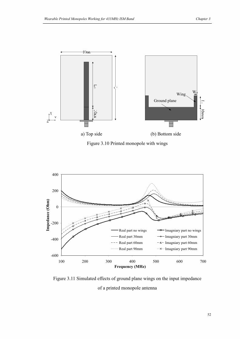
Wearable Printed Monopoles Working for 433MHz ISM Band Chapter 3
52
Ground plane
WingWw
a) Top side (b) Bottom side
Figure 3.10 Printed monopole with wings
-600
-400
-200
0
200
400
100 200 300 400 500 600 700
Frequency (MHz)
Impedance (Ohm)
Real part no wings Imagniary part no wings
Real part 30mm Imagniary part 30mm
Real part 60mm Imagniary part 60mm
Real part 90mm Imagniary part 90mm
Figure 3.11 Simulated effects of ground plane wings on the input impedance
of a printed monopole antenna

Wearable Printed Monopoles Working for 433MHz ISM Band Chapter 3
53
After simulations, 68mm was chosen as the length of the wings. The monopole
element was shortened to 192mm. A prototype was then built according to these
dimensions and is shown in Figure 3.12. It was anticipated that since the antenna was
flexible that in use its planar nature would sometimes be distorted by bending. The
simulated and measured return loss of this antenna is shown in Figure 3.13. In the
build the conductors used were made of copper-coated, non-woven polyester fabric.
This has a lower conductivity but higher loss than the perfect copper used in the
simulation. This may account for the lower Q factor (wider bandwidth) observed in
the measurement compared with the simulation. Bending in x-axis was also
considered when measuring the return loss. The antenna was doubled over (bent in
180 degrees) and fixed using a thin cotton thread shown in Figure 3.14. For this case
it was found the bandwidth became smaller which can be explained by that the
bending radiating element formed a capacitor and more reactive power was stored
around the antenna, whilst the resonant frequency was relatively stable since the
electrical length of the antenna changed little. Due to the relatively low frequency and
the requirement for a large chamber or open test site, only the simulated efficiency is
given here and this was approximately -1.8dB (66%). The simulated radiation patterns
of the 192mm and the 222mm monopoles are shown in Figure 3.15. The results show
that the patterns are similar and adding wings will not significantly change the
antenna’s radiation properties.
(a) Top side (b) Bottom side
Figure 3.12 The prototype of the wearable straight printed monopole

Wearable Printed Monopoles Working for 433MHz ISM Band Chapter 3
54
-25
-20
-15
-10
-5
0
100 200 300 400 500 600 700
Frequency (MHz)
Return Loss (dB)
Simulation
Measurement
Measurement after bending
Figure 3.13 Return Loss for the 192mm straight printed monopole
Figure 3.14 Measurement of the return loss for the bent shape of the printed monopole
X
Z
Y
X
Z
Y .

Wearable Printed Monopoles Working for 433MHz ISM Band Chapter 3
55
XZ Plane
-50-40
-30-20
-10
00°
45°
90°
135°
180°(-180°)
-135°
-90°
-45°
Co-Polar
YZ Plane
-50-40
-30-20
-10
00°
45°
90°
135°
180°(-180°)
-135°
-90°
-45°
Co-Polar
(a) 192mm monopole with wings
XZ Plane
-50
-40
-30
-20
-10
00°
45°
90°
135°
180°(-180°)
-135°
-90°
-45°
Co-Polar
YZ Plane
-50
-40
-30
-20
-10
00°
45°
90°
135°
180°(-180°)
-135°
-90°
-45°
Co-Polar
(b) 222mm monopole without wings
Figure 3.15 Comparison of simulated radiation patterns between
printed monopoles with and without wings

Wearable Printed Monopoles Working for 433MHz ISM Band Chapter 3
56
3.5.2 Effects of the human body on the parameters of a printed monopole
From Figure 3.12 we can see that the 192mm monopole is a long and narrow antenna,
and we therefore suggest that the thigh will be a good place to locate it. To study the
human body’s effects on this antenna, a simple model of human body was created [29]
- [31]. Due to the memory limitations and the computational burden of simulating
tissues, both the shape of the body and the complexity of biologic tissues have been
simplified. However, the authors of [32] and [33] have both suggested a simplified
phantom is reliable for indicative effects. Based upon my own size, the phantom was
made as a 1750mm×200mm×320mm block with two layers. The layers used were an
outer dry skin (4.8% of the total volume) and an inner muscle (95.2%), and are shown
in Figure 3.16. In reality, these two layers are the outermost ones of the human body
and are therefore located closest to a WA. These two layers have higher permittivity
and conductivity than most other human body tissues [34] and thus represent the
human body’s impacts on a WA to a greater extent. In addition, simplified phantoms
can reduce the complexity and amount of voxels required at the boundaries of
different media thus saving memory and/or simulation time. The antenna was put on
the top center of the narrow side of the model with another layer inserted in-between.
The inserted layer was used to simulate clothing. Materials used for clothing usually
have low a dielectric constant (1.1-1.7) and low loss [35]. As an average, this layer
was set to 1.4 permittivity and 0.03 loss tangent which were the same as the measured
results of felt fabric (section 3.2.4). This was useful in a later experiment that used felt
fabric to mimic clothing.
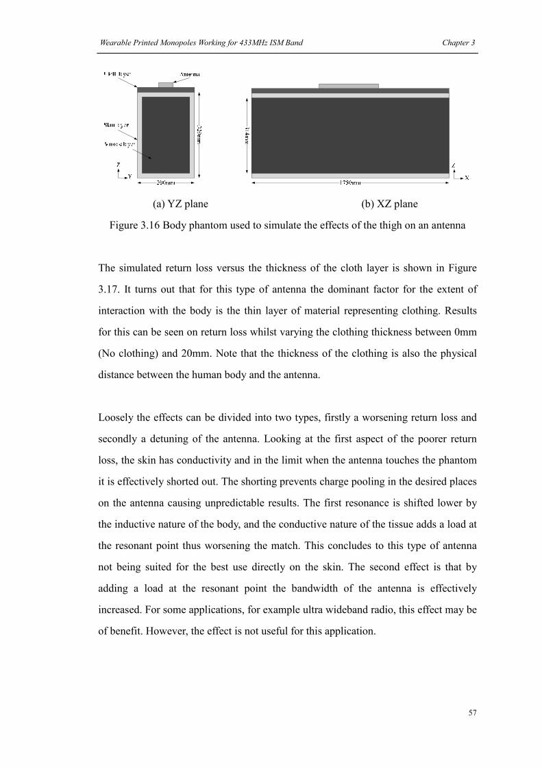
Wearable Printed Monopoles Working for 433MHz ISM Band Chapter 3
57
(a) YZ plane (b) XZ plane
Figure 3.16 Body phantom used to simulate the effects of the thigh on an antenna
The simulated return loss versus the thickness of the cloth layer is shown in Figure
3.17. It turns out that for this type of antenna the dominant factor for the extent of
interaction with the body is the thin layer of material representing clothing. Results
for this can be seen on return loss whilst varying the clothing thickness between 0mm
(No clothing) and 20mm. Note that the thickness of the clothing is also the physical
distance between the human body and the antenna.
Loosely the effects can be divided into two types, firstly a worsening return loss and
secondly a detuning of the antenna. Looking at the first aspect of the poorer return
loss, the skin has conductivity and in the limit when the antenna touches the phantom
it is effectively shorted out. The shorting prevents charge pooling in the desired places
on the antenna causing unpredictable results. The first resonance is shifted lower by
the inductive nature of the body, and the conductive nature of the tissue adds a load at
the resonant point thus worsening the match. This concludes to this type of antenna
not being suited for the best use directly on the skin. The second effect is that by
adding a load at the resonant point the bandwidth of the antenna is effectively
increased. For some applications, for example ultra wideband radio, this effect may be
of benefit. However, the effect is not useful for this application.

Wearable Printed Monopoles Working for 433MHz ISM Band Chapter 3
58
-50
-40
-30
-20
-10
0
100 200 300 400 500 600
Frequency (MHz)
Return Loss (dB)
0mm
2mm
4mm
6mm
8mm
10mm
20mm
Figure 3.17 Comparison of simulated return loss for different thickness
of the cloth layer
Figure 3.18 Simulated antenna gain and efficiency at 433MHz versus the thickness of
the cloth layer
-30
-25
-20
-15
-10
-5
0
0 2 4 6 8 10 12 14 16 18 20Thickness of cloth layer (mm)
Gain (dBi), Antenna Efficiency (dB)
Gain
Antenna efficiency
Simulated free space efficiency
-1.8dB

Wearable Printed Monopoles Working for 433MHz ISM Band Chapter 3
59
The simulated gain and antenna efficiency at 433MHz versus the thickness of the
cloth layer is shown in Figure 3.18. We can see that as the increase of cloth thickness,
the body’s impacts are weaker and better antenna gain and efficiency can be obtained.
To compare the effects of the size of the human body on the antenna, two additional
phantoms were used measuring 1800mm×300mm×420mm (Fatter) and
1600mm×150mm×220mm (Thinner). The results of return loss are shown in Figure
3.19. The results show that variations on this scale do not make too much difference
but do cause small detuning.
Subsequent to the three sets of simulations a few measurements were taken with the
antenna sewn loosely onto a pair of jeans using thin black thread. The experiment is
shown in Figure 3.20.
-50
-40
-30
-20
-10
0
100 200 300 400 500 600
Frequency (MHz)
Return Loss (dB)
0mm
2mm
4mm
6mm
8mm
10mm
20mm
(a) Simulated return loss on a fatter phantom

Wearable Printed Monopoles Working for 433MHz ISM Band Chapter 3
60
-50
-40
-30
-20
-10
0
100 200 300 400 500 600
Frequency (MHz)
Return Loss (dB)
0mm
2mm
4mm
6mm
8mm
10mm
20mm
(b) Simulated return loss on a thinner phantom
Figure 3.19 Effects of fatter and thinner phantoms on return loss
(a) Antenna sewn onto jeans (b) Measurement on thigh
Figure 3.20 Measurement of the antenna on thigh
Feed point

Wearable Printed Monopoles Working for 433MHz ISM Band Chapter 3
61
The measured thickness of the jeans and underwear was approximately 1.5mm. Six
situations were considered: the first one (Situation 1) was a person stood on the floor
with hands hung down by the side without touching the antenna. The second
(Situation 2) was the working situation with the hands lifted as to operate a machine.
The third (Situation 3) and forth (Situation 4) represented loose and tight situations
with the antenna side of the jeans was moved far from and tight to the thigh
respectively. The fifth (Situation 5) was the sitting situation with the person sat on a
chair. The sixth (Situation 6) was the winter situation in which an 8mm felt layer was
inserted between the jeans and the leg. The results for return loss are shown in Figure
3.21. In these results the resonant frequencies in all situations are between the range
307MHz and 362MHz which is similar to the simulated range 4mm-14mm.
According to the previous data, the tight situation which has a 1.5mm thickness
between the antenna and human body should have a resonant frequency lower than
264MHz. An explanation for this would be that the thigh contains many relatively low
permittivity materials such as fat and bone (see Figure 2.1) and also both the thigh and
jeans are not flat and not touched tightly to each other which will increase the actual
distance between the antenna and human body. Due to all of these a higher resonant
frequency appeared in the measurements.
307MHz——362MHz
-20
-15
-10
-5
0
100 200 300 400 500 600
Frequency (GHz)
Return Loss (dB)
Situation 1
Situation 2
Situation 3
Situation 4
Situation 5
Situation 6
Figure 3.21 Measured return loss in six different situations for the antenna on jeans

Wearable Printed Monopoles Working for 433MHz ISM Band Chapter 3
62
3.5.3 Antenna tuning for the printed monopole antenna
From section 3.5.2 we know that the 192mm wearable monopole antenna designed in
free space for ISM 433MHz band was detuned to a lower band when worn on human
body. To compensate the lowered resonant frequency, a new monopole with shorter
length Lm =165mm and Lwing =30mm was simulated in free space and on the human
body model. The return loss is shown in Figure 3.22.
-30
-20
-10
0
100 200 300 400 500 600
Frequency (MHz)
Return Loss (dB)
In free space
0mm
2mm
6mm
16mm
20mm
ISM433MHz
Figure 3.22 Simulated return loss of the tuned straight monopole
in free space and on the phantom
We can see that this antenna can cover the ISM 433MHz band when the cloth layer is
between 6mm and 16mm. The simulated antenna gain and efficiency at 433MHz
versus the thickness of the cloth layer is shown in Figure 3.23. We find the thickness
of the cloth layer has obvious effects on the antenna gain and efficiency, thicker cloth
layer tends to have better antenna gain and efficiency. In addition, to compare Figure
3.18 and Figure 3.23, two parameters, increased gain (=Gain after tuning–Gain before
tuning) and increased efficiency (=Antenna Efficiency after tuning–Antenna
Efficiency before tuning) are defined to make clear how much has been improved

Wearable Printed Monopoles Working for 433MHz ISM Band Chapter 3
63
after tuning and they are shown in Figure 3.24. It was found there was a raise for both
between 6mm and 16mm, referring to Figure 3.17 and Figure 3.22, it is obvious that
the better impedance matching in this range has improved the antenna’s performance.
-30
-25
-20
-15
-10
-5
0
0 2 4 6 8 10 12 14 16 18 20
Thickness of cloth layer (mm)
Gain (dBi) Antenna Efficiency (dB)
Gain
Antenna efficiency
Figure 3.23 Simulated antenna gain and efficiency of the tuned straight monopole on
human body versus the thickness of cloth layer
-6
-5
-4
-3
-2
-1
0
1
2
3
0 2 4 6 8 10 12 14 16 18 20
Thickness of cloth layer (mm)
Incr
ease
d g
ain (
dB
i), In
crea
sed E
ffic
iency
(dB
)
Increased gain
Increased efficiency
Figure 3.24 Achieved improvements of the antenna gain and efficiency of the tuned
straight monopole
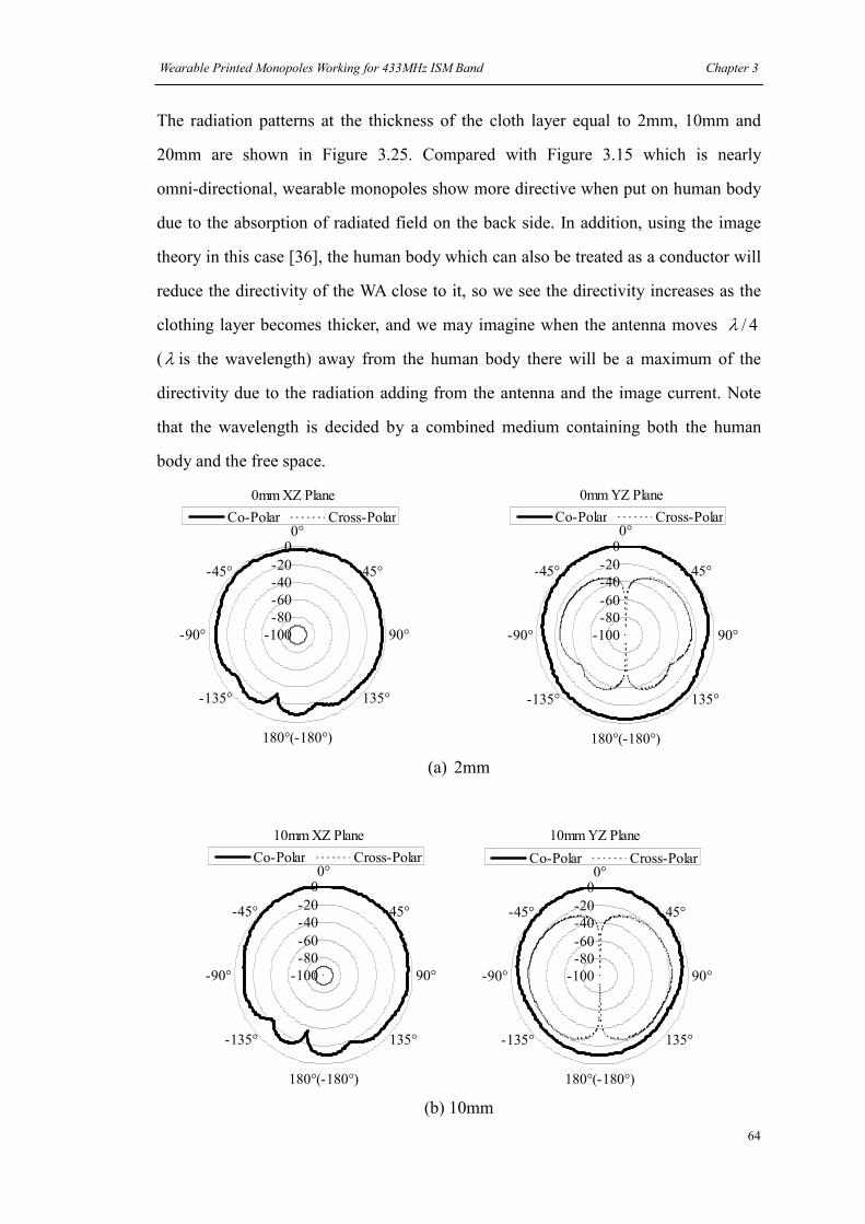
Wearable Printed Monopoles Working for 433MHz ISM Band Chapter 3
64
The radiation patterns at the thickness of the cloth layer equal to 2mm, 10mm and
20mm are shown in Figure 3.25. Compared with Figure 3.15 which is nearly
omni-directional, wearable monopoles show more directive when put on human body
due to the absorption of radiated field on the back side. In addition, using the image
theory in this case [36], the human body which can also be treated as a conductor will
reduce the directivity of the WA close to it, so we see the directivity increases as the
clothing layer becomes thicker, and we may imagine when the antenna moves 4/λ
(λ is the wavelength) away from the human body there will be a maximum of the
directivity due to the radiation adding from the antenna and the image current. Note
that the wavelength is decided by a combined medium containing both the human
body and the free space.
0mm XZ Plane
-100
-80
-60
-40
-20
00°
45°
90°
135°
180°(-180°)
-135°
-90°
-45°
Co-Polar Cross-Polar
0mm YZ Plane
-100
-80
-60
-40
-20
00°
45°
90°
135°
180°(-180°)
-135°
-90°
-45°
Co-Polar Cross-Polar
(a) 2mm
10mm XZ Plane
-100
-80
-60
-40
-20
00°
45°
90°
135°
180°(-180°)
-135°
-90°
-45°
Co-Polar Cross-Polar
10mm YZ Plane
-100
-80
-60
-40
-20
00°
45°
90°
135°
180°(-180°)
-135°
-90°
-45°
Co-Polar Cross-Polar
(b) 10mm

Wearable Printed Monopoles Working for 433MHz ISM Band Chapter 3
65
20mm XZ Plane
-100
-80
-60
-40
-20
00°
45°
90°
135°
180°(-180°)
-135°
-90°
-45°
Co-Polar Cross-Polar
20mm YZ Plane
-100
-80
-60
-40
-20
00°
45°
90°
135°
180°(-180°)
-135°
-90°
-45°
Co-Polar Cross-Polar
(c) 20mm
Figure 3.25 Simulated radiation patterns of the tuned straight monopole on the phantom
with different thickness of the cloth layer
The simulated peak SAR values are obtained and shown below. The input power was
set 10dBm. We can see that except the antenna touching human body directly, the
SAR values are relatively small. The general tendency is the SAR decreases as the
thickness of cloth layer increases, but at 6mm the SAR value has an increase since the
antenna obtains its better matching at this distance at 433MHz.
0
1
2
3
4
5
0 5 10 15 20
Thickness of cloth layer (mm)
Peak SAR (W/Kg)
Peak SAR
Figure 3.26 Simulated peak SAR values

Wearable Printed Monopoles Working for 433MHz ISM Band Chapter 3
66
Based on the simulations a prototype was built, however according to the measured
results, the prototype was optimized to Lm = 150mm and Lw = 50 to cover the desired
band. The measured return loss of this antenna in free space and on thigh is shown in
Figure 3.27. We can find the working band of this antenna covers the ISM 433MHz
band in all situations. Due to the improvement of the return loss, this antenna will
work more efficiently than the one before tuning.
-25
-20
-15
-10
-5
0
100 200 300 400 500 600
Frequency (MHz)
Return Loss (dB)
In free space
Situation 1
Situation 2
Situation 3
Situation 4
Situation 5
Situation 6
ISM433MHz
Figure 3.27 Measured return loss for the tuned straight monopole on the thigh
3.6 Wearable meander printed monopoles
3.6.1 Antenna design
It was shown in section 3.3 that using a small ground plane can reduce the size of the
printed monopole. To further reduce the size of this type of antenna a meander
radiating element can be used. These types of antennas gain their name from the
meandering form of a river and may have radiating elements that contort in space as
does a snake. The printed version is in one plane. The overall benefit of the antenna in
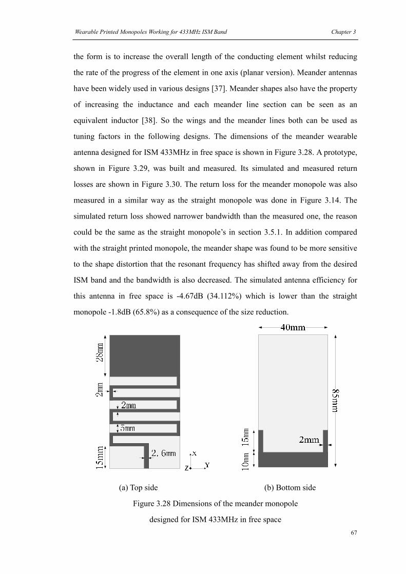
Wearable Printed Monopoles Working for 433MHz ISM Band Chapter 3
67
the form is to increase the overall length of the conducting element whilst reducing
the rate of the progress of the element in one axis (planar version). Meander antennas
have been widely used in various designs [37]. Meander shapes also have the property
of increasing the inductance and each meander line section can be seen as an
equivalent inductor [38]. So the wings and the meander lines both can be used as
tuning factors in the following designs. The dimensions of the meander wearable
antenna designed for ISM 433MHz in free space is shown in Figure 3.28. A prototype,
shown in Figure 3.29, was built and measured. Its simulated and measured return
losses are shown in Figure 3.30. The return loss for the meander monopole was also
measured in a similar way as the straight monopole was done in Figure 3.14. The
simulated return loss showed narrower bandwidth than the measured one, the reason
could be the same as the straight monopole’s in section 3.5.1. In addition compared
with the straight printed monopole, the meander shape was found to be more sensitive
to the shape distortion that the resonant frequency has shifted away from the desired
ISM band and the bandwidth is also decreased. The simulated antenna efficiency for
this antenna in free space is -4.67dB (34.112%) which is lower than the straight
monopole -1.8dB (65.8%) as a consequence of the size reduction.
(a) Top side (b) Bottom side
Figure 3.28 Dimensions of the meander monopole
designed for ISM 433MHz in free space
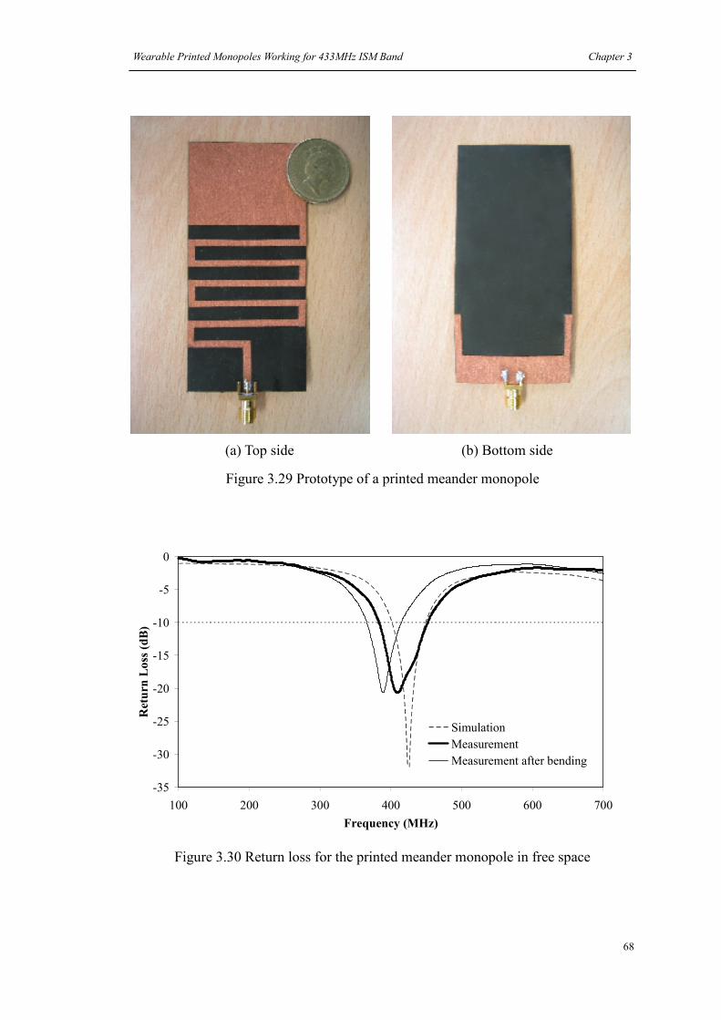
Wearable Printed Monopoles Working for 433MHz ISM Band Chapter 3
68
(a) Top side (b) Bottom side
Figure 3.29 Prototype of a printed meander monopole
-35
-30
-25
-20
-15
-10
-5
0
100 200 300 400 500 600 700
Frequency (MHz)
Return Loss (dB)
Simulation
Measurement
Measurement after bending
Figure 3.30 Return loss for the printed meander monopole in free space
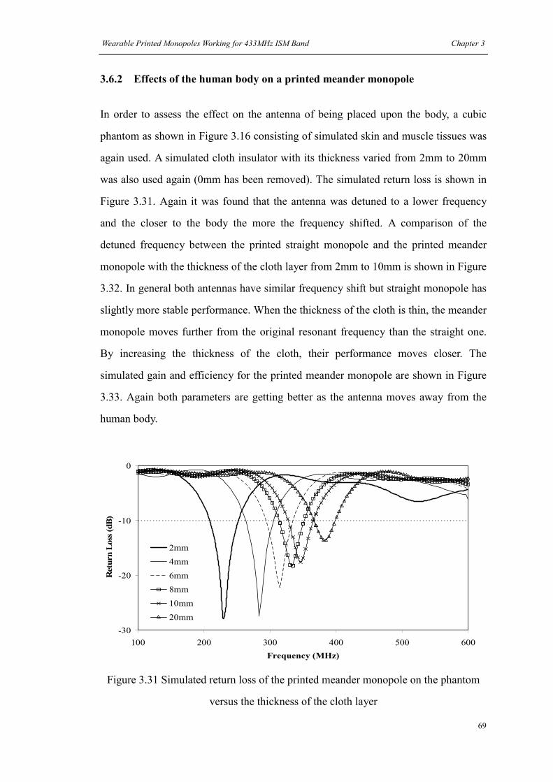
Wearable Printed Monopoles Working for 433MHz ISM Band Chapter 3
69
3.6.2 Effects of the human body on a printed meander monopole
In order to assess the effect on the antenna of being placed upon the body, a cubic
phantom as shown in Figure 3.16 consisting of simulated skin and muscle tissues was
again used. A simulated cloth insulator with its thickness varied from 2mm to 20mm
was also used again (0mm has been removed). The simulated return loss is shown in
Figure 3.31. Again it was found that the antenna was detuned to a lower frequency
and the closer to the body the more the frequency shifted. A comparison of the
detuned frequency between the printed straight monopole and the printed meander
monopole with the thickness of the cloth layer from 2mm to 10mm is shown in Figure
3.32. In general both antennas have similar frequency shift but straight monopole has
slightly more stable performance. When the thickness of the cloth is thin, the meander
monopole moves further from the original resonant frequency than the straight one.
By increasing the thickness of the cloth, their performance moves closer. The
simulated gain and efficiency for the printed meander monopole are shown in Figure
3.33. Again both parameters are getting better as the antenna moves away from the
human body.
-30
-20
-10
0
100 200 300 400 500 600
Frequency (MHz)
Return Loss (dB)
2mm
4mm
6mm
8mm
10mm
20mm
Figure 3.31 Simulated return loss of the printed meander monopole on the phantom
versus the thickness of the cloth layer
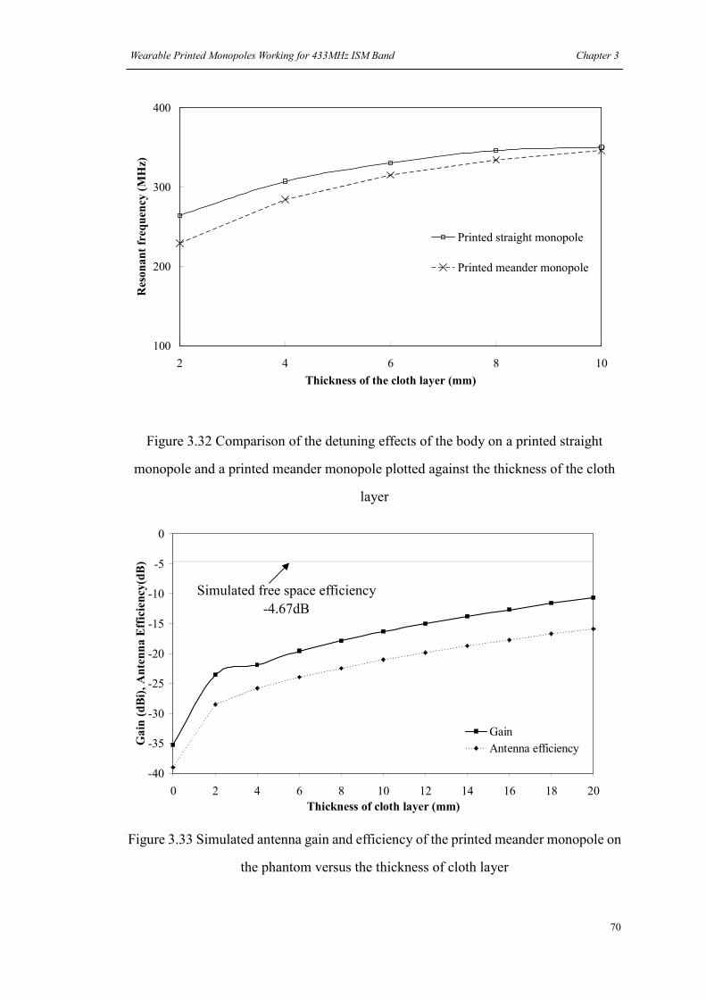
Wearable Printed Monopoles Working for 433MHz ISM Band Chapter 3
70
100
200
300
400
2 4 6 8 10
Thickness of the cloth layer (mm)
Resonant frequency (MHz)
Printed straight monopole
Printed meander monopole
Figure 3.32 Comparison of the detuning effects of the body on a printed straight
monopole and a printed meander monopole plotted against the thickness of the cloth
layer
Figure 3.33 Simulated antenna gain and efficiency of the printed meander monopole on
the phantom versus the thickness of cloth layer
-40
-35
-30
-25
-20
-15
-10
-5
0
0 2 4 6 8 10 12 14 16 18 20
Thickness of cloth layer (mm)
Gain (dBi), Antenna Efficiency(dB)
Gain
Antenna efficiency
Simulated free space efficiency
-4.67dB

Wearable Printed Monopoles Working for 433MHz ISM Band Chapter 3
71
A set of simple measurements was again done to look more closely at the effects of
the body. The antenna was sewn lightly with non conductive thread to a pair of jeans
worn by the author and the placement is shown in Figure 3.34. The measured return
loss for the printed meander monopole in the six situations previously described in
section 3.5.2 is presented in Figure 3.35. The results show that the resonance of the
antenna is shifted down by approximately 100MHz, which is similar to that seen
previously with the straight printed monopole.
3.6.3 Antenna tuning for a printed meander monopole
The results suggest therefore that to account for the detuning effect of the body the
free space version of the printed meander monopole will need to be designed to have a
higher resonance to work effectively on body. To achieve the desired result changes
were made to both the ground plane size and the dimensions of the meander. The new
size of the meander antenna is shown in Figure 3.36.
The simulated free space return loss for the meander is shown in Figure 3.37 along
with the results for the antenna perturbed by the body phantom. The results show that
the antenna is in the desired band when the simulated cloth layer is between 10mm
and 16mm. Note that for this antenna although the antenna shows the same detuning
characteristics as the straight printed monopole, the depth of the null is far more
constant. The gain and efficiency for this antenna are shown in Figure 3.38. By using
the two factors, increased gain and increased efficiency, we can find the tuned
meander monopole has an obvious optimized performance on the human body in the
ISM 433MHz band than the one before tuning which is shown in Figure 3.39.

Wearable Printed Monopoles Working for 433MHz ISM Band Chapter 3
72
(a) Antenna sewn on the jeans (b) Measurement of return loss
for an antenna on the thigh
Figure 3.34 Return Loss Measurement for a printed meander monopole on the thigh
299MHz—
—369MHz
-40
-30
-20
-10
0
100 200 300 400 500 600
Frequency (MHz)
Return Loss (dB)
Situation 1
Situation 2
Situation 3
Situation 4
Situation 5
Situation 6
Figure 3.35 Measured return loss for a printed meander monopole mounted on the thigh
for six common situations
Feed point

Wearable Printed Monopoles Working for 433MHz ISM Band Chapter 3
73
5mm
2mm
2.6mm
Y
X
40mm
20mm
(a) Top side (b) Bottom side
Figure 3.36 Dimensions of the tuned meander monopole
-30
-20
-10
0
100 200 300 400 500 600
Frequency (MHz)
Return Loss (dB)
In free space
2mm
10mm
16mm
20mm
ISM433MHz
Figure 3.37 Simulated return loss of a printed meander monopole on the body model
after tuning.
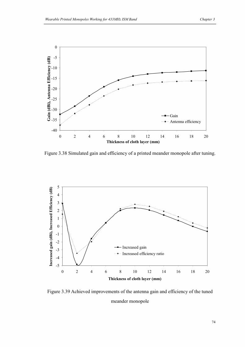
Wearable Printed Monopoles Working for 433MHz ISM Band Chapter 3
74
-40
-35
-30
-25
-20
-15
-10
-5
0
0 2 4 6 8 10 12 14 16 18 20
Thickness of cloth layer (mm)
Gain (dBi), Antenna Efficiency (dB)
Gain
Antenna efficiency
Figure 3.38 Simulated gain and efficiency of a printed meander monopole after tuning.
-5
-4
-3
-2
-1
0
1
2
3
4
5
0 2 4 6 8 10 12 14 16 18 20
Thickness of cloth layer (mm)
Increased gain (dBi), Increased Efficiency (dB)
Increased gain
Increased efficiency ratio
Figure 3.39 Achieved improvements of the antenna gain and efficiency of the tuned
meander monopole
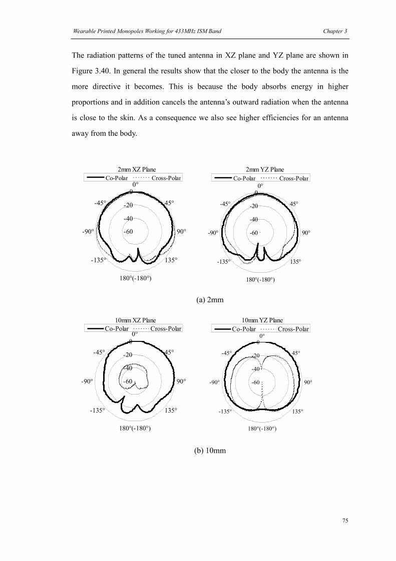
Wearable Printed Monopoles Working for 433MHz ISM Band Chapter 3
75
The radiation patterns of the tuned antenna in XZ plane and YZ plane are shown in
Figure 3.40. In general the results show that the closer to the body the antenna is the
more directive it becomes. This is because the body absorbs energy in higher
proportions and in addition cancels the antenna’s outward radiation when the antenna
is close to the skin. As a consequence we also see higher efficiencies for an antenna
away from the body.
2mm XZ Plane
-60
-40
-20
00°
45°
90°
135°
180°(-180°)
-135°
-90°
-45°
Co-Polar Cross-Polar
2mm YZ Plane
-60
-40
-20
00°
45°
90°
135°
180°(-180°)
-135°
-90°
-45°
Co-Polar Cross-Polar
(a) 2mm
10mm XZ Plane
-60
-40
-20
00°
45°
90°
135°
180°(-180°)
-135°
-90°
-45°
Co-Polar Cross-Polar
10mm YZ Plane
-60
-40
-20
00°
45°
90°
135°
180°(-180°)
-135°
-90°
-45°
Co-Polar Cross-Polar
(b) 10mm
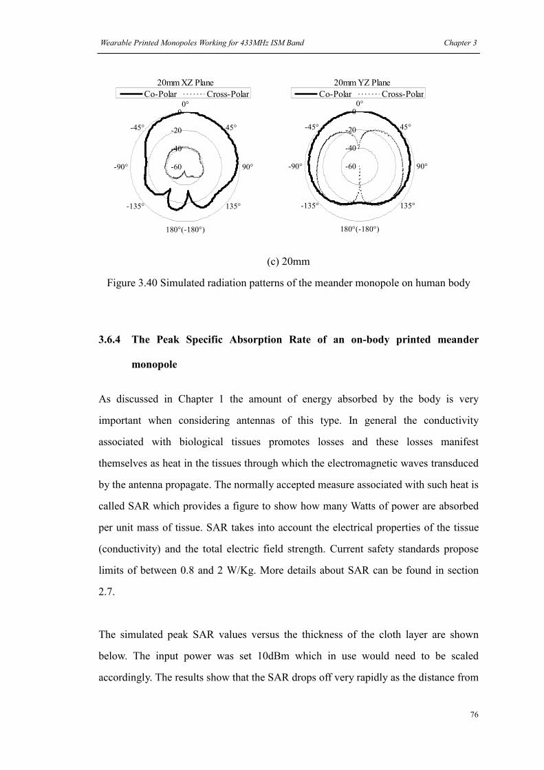
Wearable Printed Monopoles Working for 433MHz ISM Band Chapter 3
76
20mm XZ Plane
-60
-40
-20
00°
45°
90°
135°
180°(-180°)
-135°
-90°
-45°
Co-Polar Cross-Polar
20mm YZ Plane
-60
-40
-20
00°
45°
90°
135°
180°(-180°)
-135°
-90°
-45°
Co-Polar Cross-Polar
(c) 20mm
Figure 3.40 Simulated radiation patterns of the meander monopole on human body
3.6.4 The Peak Specific Absorption Rate of an on-body printed meander
monopole
As discussed in Chapter 1 the amount of energy absorbed by the body is very
important when considering antennas of this type. In general the conductivity
associated with biological tissues promotes losses and these losses manifest
themselves as heat in the tissues through which the electromagnetic waves transduced
by the antenna propagate. The normally accepted measure associated with such heat is
called SAR which provides a figure to show how many Watts of power are absorbed
per unit mass of tissue. SAR takes into account the electrical properties of the tissue
(conductivity) and the total electric field strength. Current safety standards propose
limits of between 0.8 and 2 W/Kg. More details about SAR can be found in section
2.7.
The simulated peak SAR values versus the thickness of the cloth layer are shown
below. The input power was set 10dBm which in use would need to be scaled
accordingly. The results show that the SAR drops off very rapidly as the distance from

Wearable Printed Monopoles Working for 433MHz ISM Band Chapter 3
77
the skin increases due to the simulated cloth layer. The general tendency is that the
SAR decreases as the thickness of cloth layer increases. The SAR values of the
meander monopole are generally smaller than the straight monopole. This is due to
the lower efficiency and radiated power of the printed meander antenna.
4.646
0.0090.0110.0130.0180.0240.0320.0360.0350.0440.116
0.000
1.000
2.000
3.000
4.000
5.000
0 2 4 6 8 10 12 14 16 18 20
Thickness of cloth layer (mm)
Peak SAR (W/Kg)
Peak SAR
Figure 3.41 Simulated peak SAR values of a printed meander monopole over a body
insulated by cloth of varied thickness
A prototype, shown in Figure 3.42, was built and measured. This prototype is slightly
different to the model in Figure 3.36 having similar monopole shape but with less
metallization on the upper surface (reduced from 37mm to 32mm) and two wings
were added to the ground plane to adjust the reactance. In this case a 40mm wide
ground plane and two 10mm long wings were used so as to meet the requirements of
tuning on the body. The measured return loss on the thigh in 6 situations is shown in
Figure 3.43. Results suggest that the ISM band is located in the overlap of the
working bands of the tuned printed meander monopole in all the situations so it is
suitable for the ISM 433MHz band when worn on the jeans.
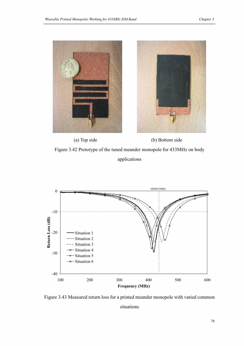
Wearable Printed Monopoles Working for 433MHz ISM Band Chapter 3
78
(a) Top side (b) Bottom side
Figure 3.42 Prototype of the tuned meander monopole for 433MHz on body
applications
-40
-30
-20
-10
0
100 200 300 400 500 600
Frequency (MHz)
Return Loss (dB)
Situation 1
Situation 2
Situation 3
Situation 4
Situation 5
Situation 6
ISM433MHz
Figure 3.43 Measured return loss for a printed meander monopole with varied common
situations

Wearable Printed Monopoles Working for 433MHz ISM Band Chapter 3
79
3.7 Conclusions
In this chapter, two different types of WAs, wearable printed straight monopoles and
wearable printed meander monopoles, are introduced and compared. These antennas
were first designed in free space for the ISM 433MHz band. To minimize antenna size,
small ground planes were used. To compensate for the detrimental effects of a smaller
than optimal ground plane, wings were added. Both simulations and measurements
show this is an efficient way to increase the matching of the antenna system without
increasing the antenna’s dimensions. Printed meander monopoles are shown to
decrease the volume of the antenna but at the cost of reduced efficiency. Subsequently
prototype antennas were simulated and measured on the body and then optimized for
the effects thereof.
In terms of return loss the meander monopole has a more attractive size than the
straight monopole, but the straight one has a more stable performance than the
meander one. The body has the effect of shifting down the resonant frequency of the
monopole antennas and increasing the antenna’s inductance. When the thickness of
the cloth is thin, the meander monopole moves further from the original resonant
frequency than the straight one.
The performance comparison between the straight monopole and the meander
monopole working for the same frequency band in free space can also be used to
judge their performance when worn on the human body. We find that although human
body is the most significant factor in worsening the antenna’s performance, a higher
performance antenna designed in free space can also work better on the body. In
addition, amending antennas’ working band (return loss less than -10dB) to the
desired frequency is important to increase the antenna’s performance. The straight
monopole showed higher SAR values than the meander monopole due to the straight
monopole’s higher radiation efficiency.

Wearable Printed Monopoles Working for 433MHz ISM Band Chapter 3
80
WAs have more directive radiation patterns when worn on the body. This was found
to be due to energy being rapidly absorbed in the tissue on the body side of the pattern.
For this reason, gain increases with the thickness of the cloth.
The working bandwidth is decided by both return loss and the thickness of cloth. The
bandwidth in terms of return loss is usually limited in a range of the cloth thickness,
say 6mm-16mm for the straight monopole and 10mm-16mm for the meander
monopole designed in this chapter.

Wearable Printed Monopoles Working for 433MHz ISM Band Chapter 3
81
References
[1] I-Fong Chen, Chia-Mei Peng and Sheng-Chieh Liang, "Single layer printed
monopole antenna for dual ISM-band operation," Antennas and Propagation, IEEE
Transactions on, vol. 53, pp. 1270-1273, 2005.
[2] Young-Pyo Hong, Jung-Min Kim, In-Sub Kim, Yong-Sik Shin and Jong-Gwan
Yook, "Circular patch loaded printed monopole antenna for PCS application,"
Antennas and Propagation Society International Symposium, 2005 IEEE, vol. 1A, pp.
255-258 Vol. 1A, 2005.
[3] Wen-Shan Chen, Yu-Chen Chang, Hong-Twu Chen, Fa-Shian Chang and
Hsin-Cheng Su, "Novel design of printed monopole antenna for WLAN/WiMAX
applications," Antennas and Propagation International Symposium, 2007 IEEE, pp.
3281-3284, 2007.
[4] Kin-Lu Wong and Yi-Fang Lin, "Stripline-fed printed triangular monopole,"
Electronics Letters, vol. 33, pp. 1428-1429, 1997.
[5] Xiao-Rong Yan, Shun-Shi Zhong and Xue-Xia Yang, "Compact Printed Monopole
Antenna with Super-wideband," Microwave, Antenna, Propagation and EMC
Technologies for Wireless Communications, 2007 International Symposium on, pp.
605-607, 2007.
[6] X. -. Yan, S. -. Zhong and G. -. Wang, "Compact printed monopole antenna with
24:1 impedance bandwidth," Electronics Letters, vol. 44, pp. 73-74, 2008.
[7] I-Fong Chen and Chia-Mei Peng, "Microstrip-fed dual-U-shaped printed
monopole antenna for dual-band wireless communication applications," Electronics
Letters, vol. 39, pp. 955-956, 2003.
[8] Ding Yuan, Du Zhengwei, Gong Ke and Feng Zhenghe, "A Four-Element Antenna
System for Mobile Phones," Antennas and Wireless Propagation Letters, IEEE, vol. 6,

Wearable Printed Monopoles Working for 433MHz ISM Band Chapter 3
82
pp. 655-658, 2007.
[9] D. Delaune, Ning Guan and K. Ito, "Multiband compact dual-arm monopole
antenna aimed at mobile phone applications," Antenna Technology: Small Antennas
and Novel Metamaterials, 2008. iWAT 2008. International Workshop on, pp. 366-369,
2008.
[10] F. Axisa, A. Dittmar and G. Delhomme, "Smart clothes for the monitoring in real
time and conditions of physiological, emotional and sensorial reactions of human,"
Engineering in Medicine and Biology Society, 2003. Proceedings of the 25th Annual
International Conference of the IEEE, vol. 4, pp. 3744-3747 Vol.4, 2003.
[11] C. Li and S. Wang, "The different demands of the smart clothing functions
among three types of hikers," E-Health Networking, Application and Services, 2007
9th International Conference on, pp. 217-220, 2007.
[12] J. C. Ribeiro, et al, "Wireless interface for sensors in smart textiles", in Proc.
Eurosensors XIX, Barcelona, Spain, pp. TC2.1-2, September 2005.
[13] Carmo, J.P.; Correia, J.H.; “RF microsystems for wireless sensors networks”,
Design & Technology of Integrated Systems in Nanoscal Era, 2009. DTIS '09. 4th
International Conference, Page(s):52 – 57, 6-9 April 2009
[14] P. B. Johns and R. L. Veurle; “Numerical solution of 2-dimensional scattering
problems using a transmission-line matrix”, Proc. Inst. Elec. Eng., Vol 118. no.9, pp.
1203-1208, Sept.1971.
[15] S. Akhtarzad and P. B. Johns, “Solution of 6-component electromagnetic fields
in three space dimensions and time by the T.L.M. method”, Electron. Lett., vol. 10, pp.
535–537, Dec. 12, 1974.
[16] Akhtarzad, S.; Johns, P.B.;, “The solutions of Maxwell’s equations in three space
dimensions and time by the TLM method of numerical analysis”, Proc. Inst. Elec.

Wearable Printed Monopoles Working for 433MHz ISM Band Chapter 3
83
Eng., vol. 122, pp. 1344–1348, Dec. 1975.
[17] Leland H. Hemming., “Electromagnetic anechoic chambers: a fundamental
design and specification guide”, Piscataway, N.J.: IEEE Press; New
York : Wiley-Interscience, 2002.
[18] W. E. McKinzie III, "A modified Wheeler cap method for measuring antenna
efficiency,"Antennas and Propagation Society International Symposium, 1997. IEEE. ,
1997 Digest, vol. 1, pp. 542-545 vol.1, 1997.
[19] Chihyun Cho, Hosung Choo, Ikmo Park and Jin-Seob Kang, "Efficiency
measurement for multi-band and broadband antennas using the modified Wheeler cap
method," Antennas and Propagation Society International Symposium 2006, IEEE, pp.
453-456, 2006.
[20] Skyworks, "Cellular Handset Antenna Efficiency Measurement Using the
Wheeler Cap," White Paper, April 18, 2007.
[21] T. Nishikawa, K. Wakino, H. Tanaka and Y. Ishikawa, "Precise Measurement
Method for Complex Permittivity of Microwave Dielectric Substrate," Precision
Electromagnetic Measurements, 1988. CPEM 88 Digest. 1988 Conference on, pp.
155-156, 1988.
[22] J. Krupka, R. G. Geyer, J. Baker-Jarvis and J. Ceremuga, "Measurements of the
complex permittivity of microwave circuit board substrates using split dielectric
resonator and reentrant cavity techniques," Dielectric Materials, Measurements and
Applications, Seventh International Conference on (Conf. Publ. no. 430), pp. 21-24,
1996.
[23] J. Richmond, "Monopole antenna on circular disk over flat earth," Antennas and
Propagation, IEEE Transactions on [Legacy, Pre - 1988], vol. 33, pp. 633-637, 1985.
[24] R. G. Fitzgerrell, "Monopole impedance and gain measurements on finite ground
planes," Antennas and Propagation, IEEE Transactions on, vol. 36, pp. 431-439,

Wearable Printed Monopoles Working for 433MHz ISM Band Chapter 3
84
1988.
[25] K. Awadalla, T. Maclean, "Input impedance of a monopole antenna at the center
of a finite ground plane," Antennas and Propagation, IEEE Transactions on [Legacy,
Pre - 1988], vol. 26, pp. 244-248, 1978.
[26] P. Salonen, L. Hurme, "A novel fabric WLAN antenna for wearable
applications," Antennas and Propagation Society International Symposium, 2003.
IEEE, vol. 2, pp. 700-703 vol.2, 2003.
[27] B. Sanz-Izquierdo, J. C. Batchelor, M. I. Sobhy,"Compact UWB Wearable
Antenna," Antennas and Propagation Conference, 2007. LAPC 2007. Loughborough,
pp. 121-124, 2007.
[28]
http://uk.rs-online.com/web/search/searchBrowseAction.html?method=getProduct&R
=0240387 (Cited on April 10, 2008)
[29] C Gabriel, S Gabriel, E Corthout,"The dielectric properties of biological tissues: I.
Literature survey," Phys. Med. Biol. 41 (1996) 2231–2249, November 1996.
[30] S Gabriel, R W Lau, C Gabriel,"The dielectric properties of biological tissues: II.
Measurements in the frequency range 10 Hz to 20 GHz," Phys. Med. Biol. 41 (1996)
2251–2269, November 1996.
[31] S Gabriel, R W Lau, C Gabriel,"The dielectric properties of biological tissues: III.
Parametric models for the dielectric spectrum of tissues," Phys. Med. Biol. 41 (1996)
2271–2293, November 1996.
[32] J. Toftgard, S. N. Hornsleth and J. B. Andersen, "Effects on portable antennas of
the presence of a person," Antennas and Propagation, IEEE Transactions on, vol. 41,
pp. 739-746, 1993.
[33] Jaehoon Kim and Y. Rahmat-Samii, "Implanted antennas inside a human body:

Wearable Printed Monopoles Working for 433MHz ISM Band Chapter 3
85
simulations, designs, and characterizations," Microwave Theory and Techniques, IEEE
Transactions on, vol. 52, pp. 1934-1943, 2004.
[34] S Gabriel, R W Lau and C Gabriel, “The dielectric properties of biological
tissues: II. Measurements in the frequency range 10 Hz to 20 GHz”, Phys. Med. Biol.
41 2251-2269, 1996
[35] P. Salonen, Y. Rahmat-Samii, M. Schaffrath, M. Kivikoski,"Effect of textile
materials on wearable antenna performance: a case study of GPS antennas," Antennas
and Propagation Society International Symposium, 2004. IEEE, vol. 1, pp. 459-462
Vol.1, 2004.
[36] Warren L. Stutzman and Gary A. Thiele, “Antenna Theory and Design, Second
Edition”. John Wiley & Sons, Inc., pp.63-68, 1998
[37] M. Sun, Y. P. Zhang, G. X. Zhcng,"Modeling and measurement of the on-chip
meander antenna pair," Microwave Conference Proceedings, 2005. APMC 2005.
Asia-Pacific Conference Proceedings, vol. 4, pp. 3 pp., 2005.
[38] T. Endo, Y. Sunahara, S. Satoh, T. Katagi,"Resonant frequency and Radiation
Efficiency of Meander Line Antennas," Electronics and Communications in Japan,
vol. Vol. 83, No. 1, 2000.
86
Chapter 4
A Wearable Multi-band Antenna
4.1 Introduction
A recent trend in electronics has been the integration of technology into clothing.
Examples range from the very simple radio frequency identity tag [1] that allows
simple item tracking, in a store or perhaps a warehouse, to more complex systems
such as the “hug shirt” [2] that allows a client remote from the wearer to contact an
item of clothing (perhaps a shirt or coat), via wireless, and cause the item to interact
with the wearer. In this latter implementation the shirt will actually hug the wearer.
Wireless and integration conclude to antennas integrated into clothing and therefore
antennas seeking the desirable properties (see Chapter 1). Flexible Multi-band
antennas are discussed in detail in this chapter. These devices may cover several
different frequency ranges across the spectrum. A useful reference for the design of
multi-band antennas that can be found is [3] in which the authors presented results for
a microstrip-fed dual-U-shaped printed monopole design for wireless communication
applications in the 2.4 and 5.8 GHz bands. Also the authors of [4] have provided
details of their work on a novel planar monopole which covered 900, 1800 and 1900
MHz operations. [5] looked in detail at a microstrip-fed printed monopole antenna
which could easily cover DCS/UMTS/WiBro/2.4 GHz WLAN and 5.2/5.8 GHz
WLAN bands at the same time.
As has been mentioned in Chapter 1 two desirable properties for wearable printed
monopoles are an omni-directional radiation pattern and good wideband performance.
As shown in [3] - [5] it can be seen that the printed monopole is a good candidate
antenna. In this chapter, a new monopole design built on a FR4 board for multi-band

A Multi-band Wearable Antenna Chapter 4
87
applications, including the GSM 900 (890–960 MHz), DCS (1710– 1880 MHz) and
PCS (1850–1990 MHz), UMTS (1920–2170 MHz), and WLAN2.4GHz
(2400-2484MHz) frequency bands, is first presented. Then, based on this design a
wearable flexible antenna is built and studied in close proximity to the human body.
4.2 A multi-band printed monopole antenna for mobile
communication applications.
4.2.1 The procedure to design a multi-band printed monopole antenna
From section 3.3 it is already known that the shape of ground plane is important in
determining the antenna’s performance. The monopoles discussed in that section were
limited to have the same width as the 50ohm feed line. However, in practice it turns
out that the shape of the monopole element also has a pronounced effect on the
antenna parameters. This can be seen in [6] where the author presented a printed
triangular monopole which had the bandwidth up to 32.5%, and also in [7] where the
authors analyzed the performance of a rectangular monopole by changing the size of a
rectangular monopole and its distance to the ground plane.
After an extensive pre-design review the starting point for this implementation was
chosen to be the rectangular monopole shown in Figure 4.1(a). The substrate was FR4
with a permittivity of 4.6 and a thickness of 1.6 mm. The simulated return loss for the
antenna in Figure 4.1(a) is shown in Figure 4.2. This antenna has a bandwidth of
approximately 23% centered about 2.8GHz. Another resonance centered at 1.7GHz
can also be found from the results but with a poor match. Therefore to be useful the
resonant frequency of the antenna at 2.8GHz needs to be lowered and widened. In line
with experience gained in previous work and discussed in section 3.5.1 two wings
were added to the ground plane to improve the impedance match so as to take
advantage both of the resonances. The new geometry for this antenna is shown in

A Multi-band Wearable Antenna Chapter 4
88
Figure 4.1(b) with the simulated return loss shown in Figure 4.2. Note that the wings
only slightly increase the metallization on the ground plane side of the PCB. We can
see the two resonances have been combined together and that the bandwidth had been
increased up to 61% which covers the range 1.306GHz to 2.458GHz. The electrical
size of the antenna was therefore increased whilst its volume remained constant. Also
as previously shown in section 3.6 and also discussed in [5] an additional band at
900MHz can be facilitated by adding two slots to the rectangular monopole. This has
the effect of providing an additional longer length current path that achieves an
additional resonance at a lower frequency but does not increase the antenna’s size.
This geometry is shown in Figure 4.1(c). By tuning the size and position of the slots, a
current can be excited along the slots to form a resonant path at 900MHz.
Using the dimensions in Figure 4.1(c), a prototype was built and is shown in Figure
4.3. Its simulated and measured return loss results are shown in Figure 4.4. The chart
shows that the band for GSM 900 has been created (simulation: 0.87GHz-1GHz,
measurement: 0.90-1.04GHz). Small differences between simulation and
measurement can be corrected by tuning the slots but in general the agreement was
found to be good. In addition, it was found on re-examination that the wings had also
positive effects on this bandwidth. Comparisons of with and without wings at
900MHz showed a better match was achieved when wings were added, see Figure 4.4.
In addition the effect of the slots was to translate the higher working band up in
frequency (simulation: 1.68GHz-2.53GHz, measurement: 1.62GHz-2.58GHz)
allowing the antenna to cover the DCS, PCS, UMTS, and WLAN2.4GHz bands.
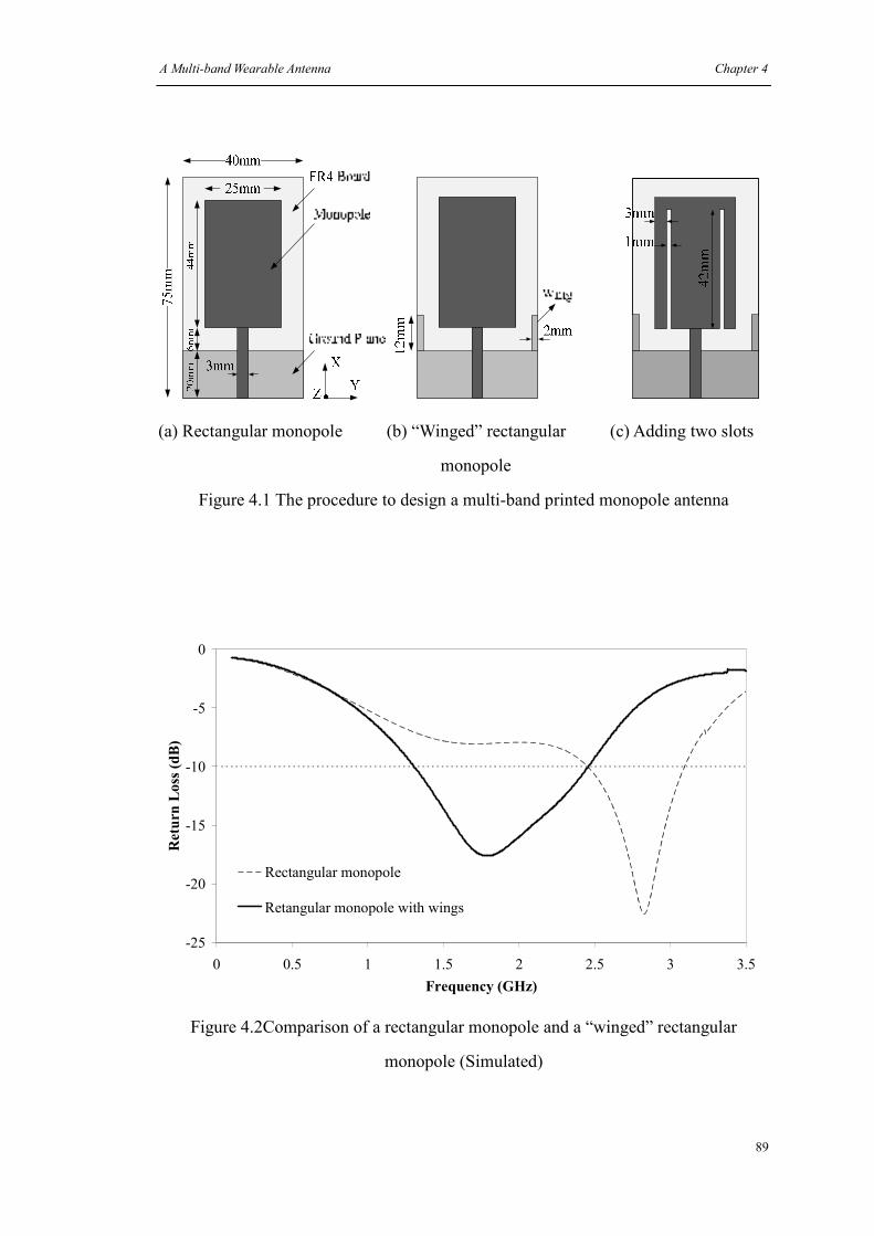
A Multi-band Wearable Antenna Chapter 4
89
(a) Rectangular monopole (b) “Winged” rectangular (c) Adding two slots
monopole
Figure 4.1 The procedure to design a multi-band printed monopole antenna
-25
-20
-15
-10
-5
0
0 0.5 1 1.5 2 2.5 3 3.5
Frequency (GHz)
Return Loss (dB)
Rectangular monopole
Retangular monopole with wings
Figure 4.2Comparison of a rectangular monopole and a “winged” rectangular
monopole (Simulated)

A Multi-band Wearable Antenna Chapter 4
90
(a) Top side (b) Bottom side
Figure 4.3 The prototype of the multi-band monopole antenna built on a FR4 board
-40
-30
-20
-10
0
0 0.5 1 1.5 2 2.5 3 3.5
Frequency (GHz)
Retrun Loss (dB)
Simulation without wings
Measurement without wings
Simulation with wings
Measurement with wings
Figure 4.4 Return losses for the multi-band printed monopole with/without wings

A Multi-band Wearable Antenna Chapter 4
91
4.3 A wearable multi-band monopole antenna on a neoprene
substrate
4.3.1 A neoprene version for the wearable multi-band monopole antenna
A printed multi-band monopole was designed and results for this are presented in
Figure 4.4. However for most wearable applications, the FR4 substrate made this
antenna too rigid to be comfortably worn. Therefore as an improvement and in line
with the discussions in Chapter 3 and [8] the substrate of this antenna was replaced
with Neoprene as shown in Figure 4.5. It turned out that since these two materials
have similar permittivity (about 4.6 for FR4 [9] (see also table 3.1) and 5.2 for
Neoprene (measured)), the shape of the antenna could be maintained for the prototype.
Note that the measured permittivity was only available for the Neoprene at spot
frequencies and therefore an average across the bandwidth was used. Best agreement
was obtained for an average of 4.8 with loss tangent 0.03. The measured results for
this antenna are shown in Figure 4.6. As shown in the figure the results show that the
antenna has the desired properties at 0.85GHz-1.02GHz and 1.65GHz-2.56GHz which
cover the relevant bands with a return loss of -10dB or better.
Several of the measured radiation patterns for the antenna shown in Figure 4.5 are
presented in Figure 4.7 (a), (b) and (c) for the frequencies 0.9, 1.8 and 2.4 GHZ
respectively. The patterns exhibit good omni-directionality which is desirable,
however this will be disturbed in later results as the antenna was brought close to the
body.

A Multi-band Wearable Antenna Chapter 4
92
(a) Top side (b) Bottom side
Figure 4.5 The prototype of the wearable multi-band monopole antenna
-40
-30
-20
-10
0
0 0.5 1 1.5 2 2.5 3 3.5Frequency (GHz)
Return Loss (dB)
Without wing
With wing
GSM900 DCS, PCS and UMTS WLAN2.4GHz
Figure 4.6 Measured return loss for the wearable multi-band monopole
antenna with/without wings (off-body)

A Multi-band Wearable Antenna Chapter 4
93
900MHz XZ Plane
-30
-20
-10
00°
45°
90°
135°
180°(-180°)
-135°
-90°
-45°
Co-Polar Cross-Polar
900MHz YZ Plane
-30
-20
-10
00°
45°
90°
135°
180°(-180°)
-135°
-90°
-45°
Co-Polar Cross-Polar
(a)
1.8GHz XZ Plane
-50-40-30-20-10
00°
45°
90°
135°
180°(-180°)
-135°
-90°
-45°
Co-Polar Cross-Polar
1.8GHz YZ Plane
-50-40-30-20-10
00°
45°
90°
135°
180°(-180°)
-135°
-90°
-45°
Co-Polar Cross-Polar
(b)
2.4GHz XZ Plane
-50-40-30-20-10
00°
45°
90°
135°
180°(-180°)
-135°
-90°
-45°
Co-Polar Cross-Polar
2.4GHz YZ Plane
-60
-40
-20
00°
45°
90°
135°
180°(-180°)
-135°
-90°
-45°
Co-Polar Cross-Polar
(c)
Figure 4.7 Measured patterns for the wearable multi-band antenna in free space

A Multi-band Wearable Antenna Chapter 4
94
4.3.2 Antenna efficiency measurement using wheeler cap method
By simulation and measurement (integration of radiated field), the efficiencies of this
antenna were found to be -4.65dB (34.3%), -0.64dB (86.3%), -0.54dB (88.3%) and
-5.67dB (27.1%), -0.83dB (82.6%), -1.03dB (78.86%) at 900MHz, 1.8GHz, and
2.4GHz respectively. A further set of values, obtained via a Wheelers cap [10] is
-3.23dB (47.5%), -0.589dB (87.3%) and -1.04dB (78.6%) respectively. The
comparison of the efficiency obtained using different methods is shown in Table 4.1.
It is found the three measurement methods have better agreement at 1.8GHz and
2.4GHz while the biggest difference appears at 900MHz. Aside from errors in the
simulation parameters, the fact that the lack of a feed in the model, cabling and
shadowing effects in the chamber are possible explanations for the differences in
efficiencies.
900MHz 1.8GHz 2.4GHz
Simulation -4.65 -0.64 -0.54
Chamber -5.67 -0.83 -1.03
Wheeler Cap -3.23 -0.589 -1.04
Table 4.1 Comparison of antenna efficiency (dB) measured in different methods
4.4 Body Sensitivity of a wearable multi-band printed monopole on
the arm.
4.4.1 Simulated results for body sensitivity of a wearable multi-band printed
monopole on the arm.
From the experiments described in Chapter 3 and as a result of the literature review
undertaken in Chapter 1 it was known that when placed near the body of a user the
antenna parameters would be changed in several ways. The antenna would be detuned
to a lower frequency; it would tend to become less efficient; its bandwidth may

A Multi-band Wearable Antenna Chapter 4
95
increase and as a result of lossy body tissue entering the radius of the radiation pattern
close to the source, the radiation pattern would become more directive in one or more
planes.
To quantify these effects prior to actual measurements an arm model was created in
Microstripes. The model used was a two-layer cylinder including an outer dry skin
with 3mm thickness and an inner muscle mass with a radius of 39mm. The geometry
of the arm representing phantom (based loosely on the authors own arm) is shown in
Figure 4.8 which also shows a variable layer of cloth with dielectric constant of 1.4
and loss tangent of 0.03, between the simulated skin and an antenna. This model did
not consider the effects of the torso on the antenna which could be significant.
However, it did enable the partial optimization of the antenna prior to construction.
For the antenna situated flat upon the arm model the simulated return loss versus the
thickness of the cloth layer is shown in Figure 4.9.
With reference to Figure 4.9 it can be seen that although no cloth layer has the widest
bandwidth the range of thicknesses 4 to 20mm is more useful. A 2mm thick section of
cloth allows the antenna to cover only some of the required bands. In comparison with
the free space iteration shown in Figure 4.6, Figure 4.9 shows that all of the working
bands have been detuned by the body to lower frequencies which, in the 2mm cloth
thickness case, negates the 900MHz band. With cloth thicknesses from 4mm to 10mm
the results show that the two higher resonances in free space are now more distinct,
whilst at 20mm they move closer together. Intuitively this can be explained by
comparing this multiband antenna to several individual antennas of varying length
and hence resonant frequencies. This concludes to each antenna having a different
electrical distance from the surface of the body. In the bandwidth of the antenna under
consideration the permittivity of human tissue tends to decrease with decreasing
frequency [11] - [13] so that higher frequencies tend to have larger electrical distances
for each of the antenna elements away from the body.
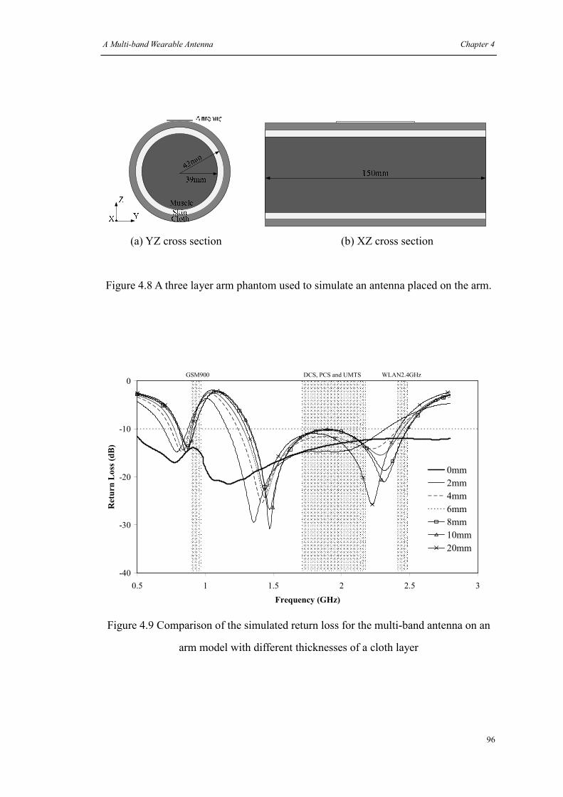
A Multi-band Wearable Antenna Chapter 4
96
(a) YZ cross section (b) XZ cross section
Figure 4.8 A three layer arm phantom used to simulate an antenna placed on the arm.
-40
-30
-20
-10
0
0.5 1 1.5 2 2.5 3
Frequency (GHz)
Return Loss (dB)
0mm
2mm
4mm
6mm
8mm
10mm
20mm
GSM900 DCS, PCS and UMTS WLAN2.4GHz
Figure 4.9 Comparison of the simulated return loss for the multi-band antenna on an
arm model with different thicknesses of a cloth layer

A Multi-band Wearable Antenna Chapter 4
97
4.4.2 Measured results for body sensitivity of a wearable multi-band printed
monopole on the arm
It was realized that the combinations of clothing worn, the site of the antenna and the
effects of any cabling errors might all have an effect on any result obtained for the
prototype antenna. However, it was thought worthwhile to undertake a series of tests
with a variety of typical combinations in the hope that the measurements might yield
additional information and perhaps trends. The items of clothing chosen were a t-shirt,
a sweater, a coat and a pair of jeans which are shown in Figure 4.10. The arm, the
chest and the leg were chosen for antenna locations. The materials of t-shirt were 11%
cotton, 25% viscose and 64% polyester; the sweater are 70% wool and 30% acrylic;
the outside of coat are 80% wool and 20% polyamide; and finally for the jeans 100%
cotton. These materials usually have very low permittivity lower than 2. At start to
eliminate one area of uncertainty the antenna was fixed to the items of clothing alone
and it was found that the clothes on their own had no obvious effects on return loss
(these results are not shown here).
Next a set of measurements was chosen to represent common usage situations. In total
eight groups of measurements were done for various antenna positions. These were
termed as t-shirt arm, t-shirt chest, sweater arm, sweater chest, coat arm, coat chest,
jean side thigh and jean back pocket. To replicate typical wear situations each group
had three measurements, including for normal, tight and loose clothing. When doing
the measurements on the sweater, the t-shirt was worn inside and both t-shirt and
sweater were worn for the measurements on coat, which represent the situations of
spring/fall and winter respectively. Attempts were made to standardize the position of
the feeding cable with reference to the body but this was difficult. Therefore the
results shown here may include some effects due to this. The measured results are
shown in Figure 4.11.

A Multi-band Wearable Antenna Chapter 4
98
(a) T-shirt (b) Antenna sewed on a t-shirt
(c) Sweater (d) Coat (e) Jeans
Figure 4.10 Cloths used for measurements

A Multi-band Wearable Antenna Chapter 4
99
-40
-30
-20
-10
0
0 0.5 1 1.5 2 2.5 3Frequency (GHz)
Return Loss (dB)
Normal
Tight
Loose
GSM900 DCS, PCS and UMTS WLAN2.4GHz
(a) Measured return loss for a multi-band antenna worn on the arm of a t-shirt for
varying degrees of fit.
-40
-30
-20
-10
0
0 0.5 1 1.5 2 2.5 3Frequency (GHz)
Return Loss (dB)
Normal
Tight
Loose
GSM900 DCS, PCS and UMTS WLAN2.4GHz
(b) Measured return loss for a multiband antenna worn on the chest of a t-shirt for
varying degree of fit.

A Multi-band Wearable Antenna Chapter 4
100
-40
-30
-20
-10
0
0 0.5 1 1.5 2 2.5 3Frequency (GHz)
Return Loss (dB)
Normal
Tight
Loose
GSM900 DCS, PCS and UMTS WLAN2.4GHz
(c) Measured return loss for a multiband antenna worn on the arm of a sweater for
varying degrees of fit.
-40
-30
-20
-10
0
0 0.5 1 1.5 2 2.5 3Frequency (GHz)
Return Loss (dB)
Normal
Tight
Loose
GSM900 DCS, PCS and UMTS WLAN2.4GHz
(d) Measured return loss for a multiband antenna worn on the chest of a sweater for
varying degrees of fit.

A Multi-band Wearable Antenna Chapter 4
101
-50
-40
-30
-20
-10
0
0 0.5 1 1.5 2 2.5 3Frequency (GHz)
Return Loss (dB)
Normal
Tight
Loose
GSM900 DCS, PCS and UMTS WLAN2.4GHz
(e) Measured return loss for a multiband antenna worn on the arm of a coat for
varying degrees of fit
-50
-40
-30
-20
-10
0
0 0.5 1 1.5 2 2.5 3Frequency (GHz)
Return Loss (dB)
Normal
Tight
Loose
GSM900 DCS, PCS and UMTS WLAN2.4GHz
(f) Measured return loss for a multiband antenna worn on the chest of a coat for
varying degrees of fit

A Multi-band Wearable Antenna Chapter 4
102
-50
-40
-30
-20
-10
0
0 0.5 1 1.5 2 2.5 3Frequency (GHz)
Return Loss (dB)
Normal
Tight
Loose
GSM90
0
DCS, PCS and UMTS WLAN2.4GHz
(g) Measured return loss for a multiband antenna worn on the thigh of a pair of jeans
for varying degrees of fit
-50
-40
-30
-20
-10
0
0 0.5 1 1.5 2 2.5 3Frequency (GHz)
Return Loss (dB)
Normal
Tight
Loose
GSM90
0
DCS, PCS and UMTS WLAN2.4GHz
(h) Measured return loss on the back pocket of a pair of jeans
Figure 4.11 Measured return loss on different locations and different cloth with
different situations for the multi-band antenna

A Multi-band Wearable Antenna Chapter 4
103
The measurement results shown in Figures 4.11 show similar results to the simulation
results shown in Figures 4.9. When worn on the t-shirt, the antenna’s resonances are
shifted down. This effect is strongest for the antenna closest to the body for the lowest
and highest antenna bands, GSM900 and WLAN2.4GHz bands. Also we can see the
two resonances at the higher resonant area are separated with the increasing distance
from the antenna to human body. In addition, the chest shows more effects than the
arm. With the normal and tight fitting on chest, both the lower and higher resonant
areas have lower resonant frequencies and wider working bandwidth than on the arm.
This concludes to higher field strengths in a greater volume of lossy tissue by
proportion.
Compared with the t-shirt location, antennas on the sweater and coat are more stable.
See Figures 4.13. The results also show differences between the arm and chest
locations where differing volumes of matter sit closer to the antenna. However this
effect is small when compared with changes to the return loss due to the thickness of
the cloth between the antenna and the body.
Therefore in these experiments the sweater or coat provided the antenna with
sufficient isolation from human body to allow the antenna to maintain its functionality
across the various bands.
4.5 The simulated gain and efficiency of a multiband antenna worn
on the body.
The simulated antenna gain and efficiency at 900MHz, 1.8GHz and 2.4GHz are shown
in Figure 4.12(a), (b) and (c). For these results the phantom referred to Figure 4.8 was
used.
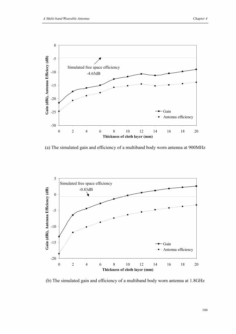
A Multi-band Wearable Antenna Chapter 4
104
(a) The simulated gain and efficiency of a multiband body worn antenna at 900MHz
(b) The simulated gain and efficiency of a multiband body worn antenna at 1.8GHz
-30
-25
-20
-15
-10
-5
0
0 2 4 6 8 10 12 14 16 18 20
Thickness of cloth layer (mm)
Gain (dBi), Antenna Efficiecy (dB)
Gain
Antenna efficiency
Simulated free space efficiency
-4.65dB
-20
-15
-10
-5
0
5
0 2 4 6 8 10 12 14 16 18 20
Thickness of cloth layer (mm)
Gain (dBi), Antenna Efficiency (dB)
Gain
Antenna efficiency
Simulated free space efficiency
-0.83dB

A Multi-band Wearable Antenna Chapter 4
105
(c) The simulated gain and efficiency of a multiband body worn antenna at 2.4GHz
Figure 4.12 Simulated antenna gain and efficiency at different frequencies on the arm
phantom versus the thickness of cloth layer
There are several trends in these results that are worth highlighting. It is apparent that
the multiband antenna is an ideal way to study the effects of the body on an antenna.
Firstly we can see that in terms of efficiency the range is from approximately 60% at
2.4 GHZ with a 20mm insulating cloth layer between the antenna and the body right
down to less than 1% for the antenna at 900MHz.
In terms of gain which is also related to efficiency the maximal gain is seen at higher
frequencies with the maximum separation from the body. On body gain for this
antenna does not exceed 3.6dBi at any frequency. The gain characteristic for this
range of frequencies has a knee which occurs below 4mm for all the resonances.
The gain and efficiency curves are not the same and neither is their rate of change as
-25
-20
-15
-10
-5
0
5
0 2 4 6 8 10 12 14 16 18 20
Thickness of cloth layer (mm)
Gain (dBi), Antenna Efficiency (dB)
Gain
Antenna efficiency
Simulated free space efficiency
-1.04dB

A Multi-band Wearable Antenna Chapter 4
106
the antenna approaches the body since they are plotted log vs. linear.
-16
-14
-12
-10
-8
-6
-4
-2
0
0 2 4 6 8 10 12 14 16 18 20
Thickness of cloth layer (mm)
Return Loss (dB)
900MHz
Figure 4.13 Simulated return loss at 900MHz on the arm phantom versus the thickness
of cloth layer
The last of these results shows the return loss of the antenna as it was moved away
from the body at a frequency of 900MHz. Return loss is less a function of proximity
to the body than either gain or efficiency. In fact for this antenna the match is actually
improved by close proximity. A limitation of the usefulness of return loss as an
antenna parameter is that it measures the ratio of the portion of energy actually
reflected to that transmitted rather than that portion of energy radiated. In this case for
the antenna with no insulating layer we see a good match mainly due to the fact that
most of the energy incident on the terminals of the antenna is being absorbed by the
lossy tissue of the body.
A Multi-band Wearable Antenna Chapter 4
107
4.6 Antenna tuning for a multiband printed monopole antenna on a
t-shirt arm
From sections 4.42 it can be seen that both an antenna on a sweater and a coat have
the desired performance and may be used as is for that application. Therefore the
following tuning is for the t-shirt arm antenna only.
To correct the antenna’s working bands, a new antenna with higher resonant
frequencies in free space was designed. This was achieved by shortening the length of
the slots and the monopole and can be seen in Figure 4.14. The simulated and
measured return loss for the tuned antenna in free space is shown in Figure 4.15 and a
good agreement is found. Compared with Figure 4.6, the tuned antenna has higher
resonant frequencies which can be used to compensate the human body’s high
permittivity effects. This antenna was also simulated on the arm model and the
simulated return loss is shown in Figure 4.16. The working bands of the tuned antenna
are able to cover the desired frequencies except when the clothing is thicker than 8mm
the return loss around 2GHz is slightly higher than -10dB due to the separation of two
resonances.
The simulated antenna gain and efficiency of the tuned antenna are shown in Figure
4.18 and their improvements are shown in Figure 4.19. Compared with the results
before tuning, the antenna has an obvious improvement at 900MHz, but at 1.8GHz
and 2.4GHz its performance is stable with a slight improvement or even regress. It
shows the return loss has crucial impacts on the antenna’s performance. By re-tuning
the antenna back to 900MHz, the antenna gain and efficiency are both increased by
more than 1dB. While due to the stable return loss at other frequencies, the antenna
gain and efficiency are relatively stable as well.

A Multi-band Wearable Antenna Chapter 4
108
40
mm
26m
m
38m
m
75
mm
40mm
2mmGround Plane
Neoprene
Wing10
mm
20
mm
(a) Top side (b) Bottom side
(c) Prototype
Figure 4.14 Antenna dimensions and the prototype for a tuned multiband body worn
antenna to be used on the arm of a t-shirt
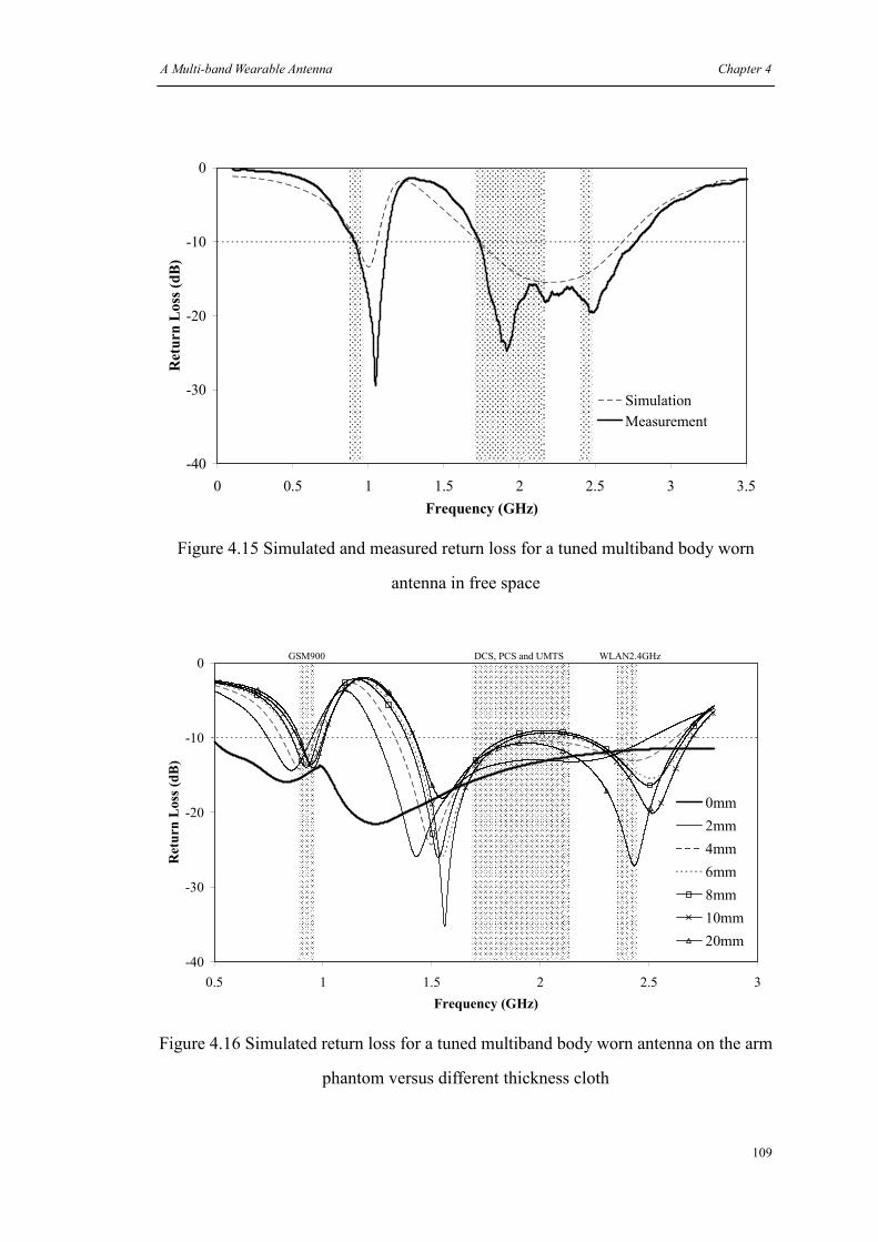
A Multi-band Wearable Antenna Chapter 4
109
-40
-30
-20
-10
0
0 0.5 1 1.5 2 2.5 3 3.5
Frequency (GHz)
Return Loss (dB)
Simulation
Measurement
Figure 4.15 Simulated and measured return loss for a tuned multiband body worn
antenna in free space
-40
-30
-20
-10
0
0.5 1 1.5 2 2.5 3
Frequency (GHz)
Return Loss (dB)
0mm
2mm
4mm
6mm
8mm
10mm
20mm
GSM900 DCS, PCS and UMTS WLAN2.4GHz
Figure 4.16 Simulated return loss for a tuned multiband body worn antenna on the arm
phantom versus different thickness cloth
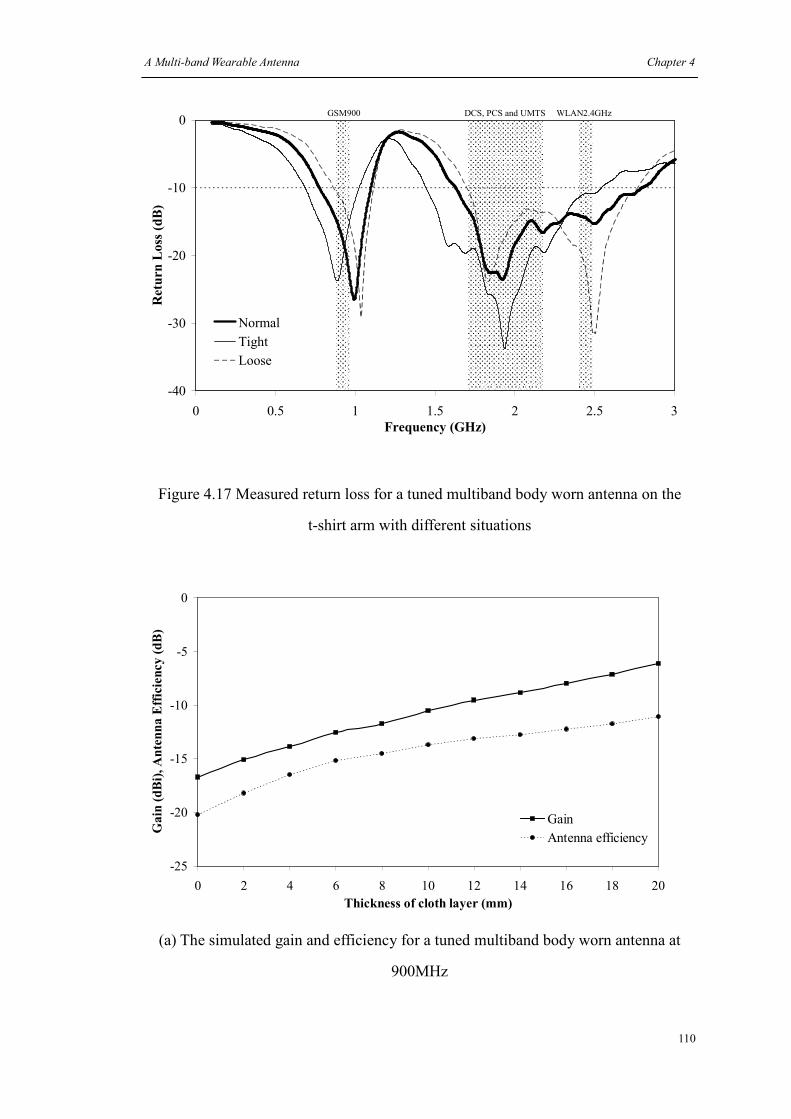
A Multi-band Wearable Antenna Chapter 4
110
-40
-30
-20
-10
0
0 0.5 1 1.5 2 2.5 3
Frequency (GHz)
Return Loss (dB)
Normal
Tight
Loose
GSM900 DCS, PCS and UMTS WLAN2.4GHz
Figure 4.17 Measured return loss for a tuned multiband body worn antenna on the
t-shirt arm with different situations
-25
-20
-15
-10
-5
0
0 2 4 6 8 10 12 14 16 18 20
Thickness of cloth layer (mm)
Gain (dBi), Antenna Efficiency (dB)
Gain
Antenna efficiency
(a) The simulated gain and efficiency for a tuned multiband body worn antenna at
900MHz

A Multi-band Wearable Antenna Chapter 4
111
-20
-15
-10
-5
0
5
0 2 4 6 8 10 12 14 16 18 20
Thickness of cloth layer (mm)
Gain (dBi), Antenna Efficiency (dB)
Gain
Antenna efficiency
(b) The simulated gain and efficiency for a tuned multiband body worn antenna at
1800MHz
-25
-20
-15
-10
-5
0
5
10
0 2 4 6 8 10 12 14 16 18 20
Thickness of cloth layer (mm)
Gain (dBi), Antenna Efficiency (dB)
Gain
Antenna efficiency
(c) The simulated gain and efficiency for a tuned multiband body worn antenna at
2400MHz
Figure 4.18 Simulated antenna gain and efficiency at different frequencies for the tuned
antenna on the arm phantom

A Multi-band Wearable Antenna Chapter 4
112
0
1
2
3
4
5
0 2 4 6 8 10 12 14 16 18 20
Thickness of cloth layer (mm)
Increased gain (dBi), Increased Efficiency (dB)
Increased gain
Increased efficiency
(a) 900MHz
-1
-0.8
-0.6
-0.4
-0.2
0
0.2
0.4
0.6
0.8
1
0 2 4 6 8 10 12 14 16 18 20
Thickness of cloth layer (mm)
Increased gain (dBi), Increased Efficiency (dB)
Increased gain
Increased efficiency
(b) 1800MHz

A Multi-band Wearable Antenna Chapter 4
113
-0.4
-0.2
0
0.2
0.4
0.6
0.8
1
1.2
0 2 4 6 8 10 12 14 16 18 20
Thickness of cloth layer (mm)
Increased gain (dBi)
Increased gain
Increased efficiency
(c) 2400MHz
Figure 4.19 Improvement of antenna gain and efficiency for the tuned antenna at
different frequencies
The simulated peak SAR values with 10dBm input power are shown in Figure 4.20. A
few measurements were also done using DASY4 [14] to study the SAR values. The
liquid used for the measurements was for simulating human head tissues at 900MHz,
1800MHz and 2450MHz. A 4mm felt layer was inserted between the phantom and the
antenna to simulate the clothing. The results are shown in Table 4.2. From the
simulation and measurement results, we can see the isolation of the clothing layer is
useful to reduce the SAR values.
Radiation patterns measured at 900MHz, 1800MHz and 2400MHz for this antenna on
the human body are shown in Figure 4.21. In these measurements human perturbation
was mimicked using a fresh 1.4kg pork leg joint from Sainsbury’s supermarket with a
2.5mm section of felt between the antenna and the meat. The pork proves to have
similar electrical properties to the human body tissue [15] [16], so is a feasible
replacement. The antenna was attached to the meat with its ground plane parallel to
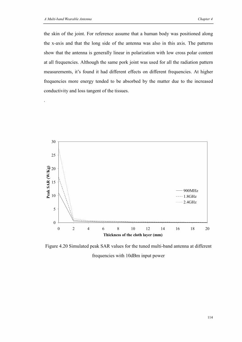
A Multi-band Wearable Antenna Chapter 4
114
the skin of the joint. For reference assume that a human body was positioned along
the x-axis and that the long side of the antenna was also in this axis. The patterns
show that the antenna is generally linear in polarization with low cross polar content
at all frequencies. Although the same pork joint was used for all the radiation pattern
measurements, it’s found it had different effects on different frequencies. At higher
frequencies more energy tended to be absorbed by the matter due to the increased
conductivity and loss tangent of the tissues.
.
0
5
10
15
20
25
30
0 2 4 6 8 10 12 14 16 18 20
Thickness of the cloth layer (mm)
Peak SAR (W/Kg)
900MHz
1.8GHz
2.4GHz
Figure 4.20 Simulated peak SAR values for the tuned multi-band antenna at different
frequencies with 10dBm input power

A Multi-band Wearable Antenna Chapter 4
115
900MHz
with/without felt
1800MHz
with/without felt
2450MHz
with/without felt
Peak SAR (W/kg) 0.111 / 0.54 0.393 / 0.776 0.71 / 0.841
SAR 1g (W/kg) 0.07 / 0.249 0.24 / 0.474 0.4 / 0.442
SAR 10g (W/kg) 0.042 / 0.133 0.129 / 0.241 0.187 / 0.201
Table 4.2 Measured SAR values for the tuned multi-band antenna at different
frequencies with 10dBm input power
900MHz YZ Plane
-40
-30
-20
-10
00°
45°
90°
135°
180°(-180°)
-135°
-90°
-45°
Co-Polar Cross-Polar
900MHz XZ Plane
-40
-30
-20
-10
00°
45°
90°
135°
180°(-180°)
-135°
-90°
-45°
Co-Polar Cross-Polar
(a)
1800MHz YZ Plane
-40
-30
-20
-10
0
0°
45°
90°
135°
180°(-180°)
-135°
-90°
-45°
Co-Polar Cross-Polar
1800MHz XZ Plane
-40
-30
-20
-10
00°
45°
90°
135°
180°(-180°)
-135°
-90°
-45°
Co-Polar Cross-Polar
(b)

A Multi-band Wearable Antenna Chapter 4
116
2400MHz YZ Plane
-40
-30
-20
-10
00°
45°
90°
135°
180°(-180°)
-135°
-90°
-45°
Co-Polar Cross-Polar
2400MHz XZ Plane
-40
-30
-20
-10
00°
45°
90°
135°
180°(-180°)
-135°
-90°
-45°
Co-Polar Cross-Polar
(c)
Figure 4.21 Measured radiation patterns for the tuned multiband body worn antenna on
a 1.4kg pork leg joint at different frequencies
4.7 Conclusions
In this chapter, a wearable multi-band monopole antenna was designed and tested on
human body. By using wings and slots, a printed monopole which can cover the GSM
900, DCS, PCS, UMTS and WLAN2.4GHz bands was first presented. The antenna
has good efficiencies and nearly omni-directional radiation patterns. Following, a WA
using the same shape as the printed monopole’s was simulated and measured on
human body. By adjusting the size of the antenna, a tuned antenna was finally
designed for wearing on t-shirt arm. The results were used to make the following
observations.
1) Working bands
An insulating cloth layer has a significant effect that increases with frequency.
2) Antenna efficiency
For a multiband antenna the rate of change of detuning as the antenna is moved closer

A Multi-band Wearable Antenna Chapter 4
117
to the body is more significant for lower frequency resonances. Therefore it is the
lowest band that requires careful attention.
3) Separation between resonances
A narrower bandwidth performance in free space might be needed when putting a
multi-resonance combined antenna on the human body. To achieve a wide band
performance, combining different resonances together is a commonly used method.
Due to the different effects on different frequencies from the human body, these
resonances will be separated again on closing to the body. When these resonances
have a looser combination in free space to achieve a wider band performance, there
will be a risk to have a notch band appearing between them. So the resonances of a
wearable multi-band printed monopole might need a tighter combination and
narrower band performance in free space.

A Multi-band Wearable Antenna Chapter 4
118
References
[1] S. Rao, N. Thanthry and R. Pendse, "RFID Security Threats to Consumers: Hype
vs. Reality," Security Technology, 2007 41st Annual IEEE International Carnahan
Conference on, pp. 59-63, 2007.
[2] http://www.cutecircuit.com/ (Cited on April 27, 2008)
[3] I-Fong Chen, Chia-Mei Peng, "Microstrip-fed dual-U-shaped printed monopole
antenna for dual-band wireless communication applications," Electronics Letters, vol.
39, pp. 955-956, 2003.
[4] Shyh-Tirng Fang, Meng-Hann Shieh, "Compact monopole antenna for
GSM/DCS/PCS mobile phone," Microwave Conference Proceedings, 2005. APMC
2005. Asia-Pacific Conference Proceedings, vol. 4, pp. 4 pp., 2005.
[5] K. Seol, J. Jung, J. Choi,"Multi-band monopole antenna with inverted U-shaped
parasitic plane," Electronics Letters, vol. 42, pp. 844-845, 2006.
[6] Kin-Lu Wong and Yi-Fang Lin, "Stripline-fed printed triangular monopole,"
Electronics Letters, vol. 33, pp. 1428-1429, 1997.
[7] M. John, M. J. Ammann, "Optimization of impedance bandwidth for the printed
rectangular monopole antenna," MICROWAVE AND OPTICAL TECHNOLOGY
LETTERS, vol. Vol. 47, No. 2, October 20 2005.
[8] L. Ma, R. M. Edwards, S. Bashir and M. I. Khattak, "A wearable flexible
multi-band antenna based on a square slotted printed monopole," Antennas and
Propagation Conference, 2008. LAPC 2008. Loughborough, pp. 345-348, 2008
[9] A. R. Djordjevi, R. M. Biljie, V. D. Likar-Smiljanic and T. K. Sarkar, "Wideband
frequency-domain characterization of FR-4 and time-domain causality,"
Electromagnetic Compatibility, IEEE Transactions on, vol. 43, pp. 662-667, 2001.

A Multi-band Wearable Antenna Chapter 4
119
[10] Skyworks, "Cellular Handset Antenna Efficiency Measurement Using the
Wheeler Cap," White Paper, April 18, 2007.
[11] C Gabriel, S Gabriel, E Corthout, "The dielectric properties of biological tissues:
I. Literature survey," Phys. Med. Biol. 41 (1996) 2231–2249, November 1996.
[12] S Gabriel, R W Lau, C Gabriel, "The dielectric properties of biological tissues: II.
Measurements in the frequency range 10 Hz to 20 GHz," Phys. Med. Biol. 41 (1996)
2251–2269, November 1996.
[13] S Gabriel, R W Lau, C Gabriel, "The dielectric properties of biological tissues:
III. Parametric models for the dielectric spectrum of tissues," Phys. Med. Biol. 41
(1996) 2271–2293, November 1996.
[14] http://www.semcad.com/measurement/support/dasy4/index.php (Cited on May
12, 2008)
[15] Jung-Mu Kim; Dong Hoon Oh; Jae-Hyoung Park; Jei-Won Cho; Youngwoo
Kwon; Changyul Cheon; Yong-Kweon Kim; "Permittivity measurement for biological
application using micromachined probe", Microwave Symposium Digest, IEEE MTT-S
International, 2005
[16] Garton, A.J.; Land, D.V.; "Dielectric tissue measurements using a co-axial probe
with a quarter-wave choke", IEE Colloquium on Application of Microwaves in
Medicine, Page(s): 10/1 - 10/6, 1995

120
Chapter 5
A Wearable UWB Antenna with a Notch
Band at WLAN5GHz
5.1 Introduction
Ultra-Wide Band (UWB) radio has recently been researched for the possibility of
providing a short range (10m or less) high bandwidth (> 1 Gbps) communication link
[1]-[3]. There are several versions of UWB but currently the most popular one has the
bandwidth of 3.1GHz - 10.6GHz. The average emission limit as defined by the FCC
for the regulation of indoor UWB systems shows that UWB is essentially now a low
power technology [4]. Low power, for example -41dBm/MHz at 4GHz allows UWB
to coexist with other spectral users that typically have noise floors greater than this
power level. However there are some bands within UWB spectra in which other low
power systems are already in operation. One example is 5GHz (5.15GHz-5.875GHz)
WLAN (Wireless Local Area Network) [5]. Previously UWB antennas have been
designed with stop bands to facilitate other technologies. For example the authors of
[6] discussed a planar ultra wide band slot antenna with frequency band notch
function and those of [7] presented results for a parametric study of a band-notched
UWB planar monopole antenna at WLAN 5GHz.
In addition to the area of in-band low power technologies a second area of
consideration when designing UWB antennas is a growing interest in wearable
computer systems or so called “smart clothing” in which computers and radios made
of flexible circuits are embedded into garments. For example a wearable Half-Disk
UWB antenna made of flexible conductive materials was introduced in [8], and
another example of a UWB textile antenna designed for body area network was
presented in [9].

A Wearable UWB Antenna with a Notch Band at WLAN5GHz Chapter 5
121
In this Chapter, a wearable printed monopole antenna which covers the UWB
frequency band 3.1GHz-10.6GHz and has a notch at WLAN5GHz band will be
presented. Neoprene was used as a substrate and since a wide-band dielectric
measurement was not available, initially it was assumed that an average permittivity
of 4.5 for neoprene over the range of UWB frequency was reasonable. The loss
properties of neoprene used were initially chosen as those measured in the split
resonator in 1.925GHz. The effects of the antenna shape and the loss properties of the
substrate on the resonant performance especially at the notch band are studied. Human
body effects are analyzed by simulations and measurements. Results of return loss,
far-field radiation patterns and SAR values are given here.
5.2 Design of a wearable UWB antenna with a notch at WLAN5GHz
band
A monopole can achieve a wideband performance by using overlapping [10] [11]. For
this particular antenna which is a square monopole, it was found that symmetrically
cutting off two corners from the base (shown in Figure 5.1), can be used as a method
to control several resonances to move closer to cover the UWB band (Figure 5.2) [12].
Differences between the simulated and measured return loss results are most likely
due to differences in the properties of the Neoprene across the band. The dimensions
of the two cut off corners are the key factors in adjusting the relative positions of
these resonances.
To avoid the low power in-band WLAN5GHz band (5.15GHz-5.875GHz) a notch is
needed. Some methods to create a notch can be found in [11] [12] [14]. In this
research, to create a notch, a central leg was inserted into the radiating element which
is shown in Figure 5.3. The stop band characteristics are associated with the tuning of
the central leg and the two slots which are symmetrical about the long axis of the
antenna. At the desired frequency strong anti-phase currents are apparent along the
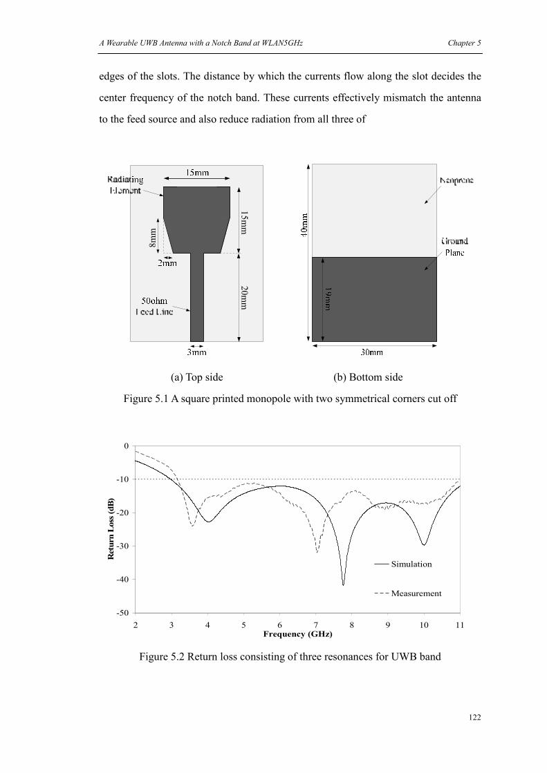
A Wearable UWB Antenna with a Notch Band at WLAN5GHz Chapter 5
122
edges of the slots. The distance by which the currents flow along the slot decides the
center frequency of the notch band. These currents effectively mismatch the antenna
to the feed source and also reduce radiation from all three of
15
mm
20
mm
8m
m
(a) Top side (b) Bottom side
Figure 5.1 A square printed monopole with two symmetrical corners cut off
-50
-40
-30
-20
-10
0
2 3 4 5 6 7 8 9 10 11Frequency (GHz)
Return Loss (dB)
Simulation
Measurement
Figure 5.2 Return loss consisting of three resonances for UWB band

A Wearable UWB Antenna with a Notch Band at WLAN5GHz Chapter 5
123
mm3mm12Slot ×
(a) Dimensions of the top side (b) Dimensions of the bottom side
(c) Prototype of the top side (d) Prototype of the bottom side
Figure 5.3 The dimensions and prototype of the notched UWB antenna

A Wearable UWB Antenna with a Notch Band at WLAN5GHz Chapter 5
124
the legs. Note that to achieve anti-phase currents along the slots it is necessary to have
unequal length legs. This can be explained as follows. A feeding point at the centre of
equal length legs has an input impedance less than the source. There is a similar
theory used in the feeding off center of patch antennas to excite anti-phase currents
along the slots.
Simulations were done to study the effects of the slot dimensions on the return loss.
Compared with the return loss of the UWB antenna in Figure 5.2, with the addition of
the two slots a notch appears. Deeper and wider slots can increase the notch
bandwidth and Q. This is shown in Figure 5.4. The notch shifts with the different size
slots. Note that at the notch the match was worsened below -10dB which has become
the acceptable matching level for antennas of this type. In addition, we also found that
the slots had some effects on the other frequencies. In simulations the efficiency of the
antenna at frequencies other than the notch was above -0.457dB (90%), whilst with
slot size 12mm×3mm it decreased the efficiency to approximately -4.68dB (34%) at
the peak value of the notch band.
-50
-40
-30
-20
-10
0
2 3 4 5 6 7 8 9 10 11
Frequency (GHz)
Return Loss (dB)
Slot 12mm x 1mm
Slot 12mm x 3mm
Slot 14mm x 1mm
Figure 5.4 Simulated effects of different dimension slots on the return loss

A Wearable UWB Antenna with a Notch Band at WLAN5GHz Chapter 5
125
After simulated tuning of the slots an initial experiment was done to estimate the
influence of the loss in the dielectric substrate. The results were obtained to help judge
the effect of material variability on the Q factor of this WLAN5GHz notch. The
conductivity of the substrate was varied and the results of return loss are shown in
Figure 5.5. The figure shows that the antenna covers the UWB band and a notch can
be found at WLAN5GHz band for the low loss antennas. In general for each spot
frequency the antenna efficiency falls off as a negative exponential with increasing
conductivity. While at frequencies around the notch the antenna is generally less
efficient although the notch disappeared with high loss substrates. The data is shown
in Table 5.1. We picked 4GHz, 6 GHz, 8 GHz, 10GHz and 5.8 GHz which is
approximately where the peak value of the notch appeared as our spot frequencies.
Note that the different conductivities are test data for Q factor studies, not real values
of the Neoprene.
A prototype, shown in Figure 5.3(b), with the same dimensions as in Figure 5.3(a)
was built and measured. The return loss for the notched UWB antenna is shown in
Figure 5.6. Note that the simulated version had an assumed substrate conductivity of
0.07s/m. The antenna efficiency and gain measured in an anechoic chamber are
-1.67dB (68.1%), -7.1dB (19.48%) and -5.12dB (30.71%) for the efficiency and
2.76dBi, -0.67dBi and -0.72dBi for the gain at 4GHz, 5.5GHz and 6GH respectively.
These values are similar to the simulated ones with substrate conductivity 0.07s/m. To
get a better agreement between simulations and measurements, the averaged
conductivity of 0.07s/m will be used here and for later simulations at the UWB
frequency band.
Radiation patterns were also measured for 4GHz and 6GHz which are shown in
Figure 5.7. They show the antenna has a nearly omni-directional radiation pattern at
these frequencies in free space.
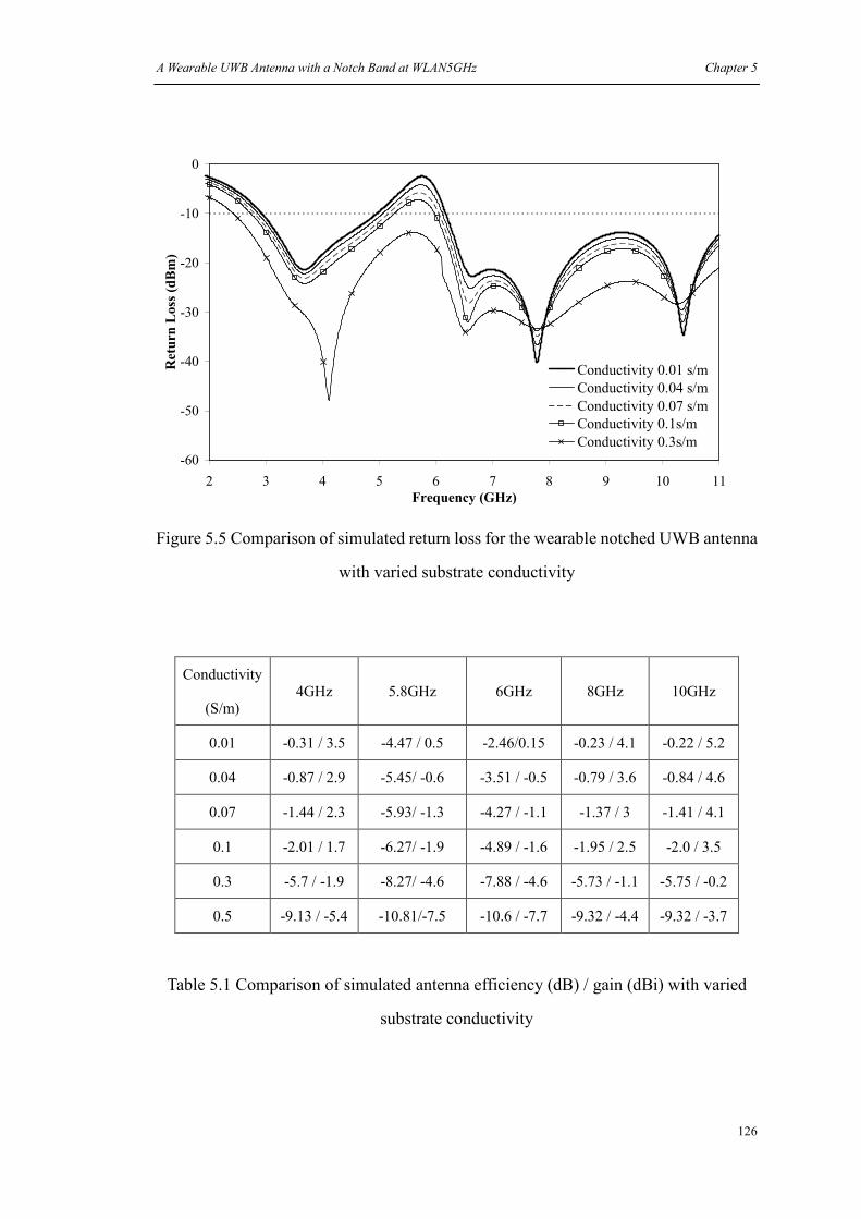
A Wearable UWB Antenna with a Notch Band at WLAN5GHz Chapter 5
126
-60
-50
-40
-30
-20
-10
0
2 3 4 5 6 7 8 9 10 11
Frequency (GHz)
Return Loss (dBm)
Conductivity 0.01 s/m
Conductivity 0.04 s/m
Conductivity 0.07 s/m
Conductivity 0.1s/m
Conductivity 0.3s/m
Figure 5.5 Comparison of simulated return loss for the wearable notched UWB antenna
with varied substrate conductivity
Conductivity
(S/m) 4GHz 5.8GHz 6GHz 8GHz 10GHz
0.01 -0.31 / 3.5 -4.47 / 0.5 -2.46/0.15 -0.23 / 4.1 -0.22 / 5.2
0.04 -0.87 / 2.9 -5.45/ -0.6 -3.51 / -0.5 -0.79 / 3.6 -0.84 / 4.6
0.07 -1.44 / 2.3 -5.93/ -1.3 -4.27 / -1.1 -1.37 / 3 -1.41 / 4.1
0.1 -2.01 / 1.7 -6.27/ -1.9 -4.89 / -1.6 -1.95 / 2.5 -2.0 / 3.5
0.3 -5.7 / -1.9 -8.27/ -4.6 -7.88 / -4.6 -5.73 / -1.1 -5.75 / -0.2
0.5 -9.13 / -5.4 -10.81/-7.5 -10.6 / -7.7 -9.32 / -4.4 -9.32 / -3.7
Table 5.1 Comparison of simulated antenna efficiency (dB) / gain (dBi) with varied
substrate conductivity

A Wearable UWB Antenna with a Notch Band at WLAN5GHz Chapter 5
127
-40
-30
-20
-10
0
2 3 4 5 6 7 8 9 10
Frequency (GHz)
Return Loss (dB)
Simulation
Measurement
Figure 5.6 The return loss for the notched UWB antenna in free space
3.5GHz XZ Plane
-40
-30
-20
-10
00°
45°
90°
135°
180°(-180°)
-135°
-90°
-45°
Co-Polar Cross-Polar3.5GHz YZ Plane
-40
-30
-20
-10
00°
45°
90°
135°
180°(-180°)
-135°
-90°
-45°
Co-Polar Cross-Polar
(a) 3.5GHz

A Wearable UWB Antenna with a Notch Band at WLAN5GHz Chapter 5
128
4GHz XZ Plane
-40
-30
-20
-10
00°
45°
90°
135°
180°(-180°)
-135°
-90°
-45°
Co-Polar Cross-Polar
4GHz YZ Plane
-40
-30
-20
-10
00°
45°
90°
135°
180°(-180°)
-135°
-90°
-45°
Co-Polar Cross-Polar
(b) 4GHz
4.5GHz XZ Plane
-40
-30
-20
-10
00°
45°
90°
135°
180°(-180°)
-135°
-90°
-45°
Co-Polar Cross-Polar4.5GHz YZ Plane
-40
-30
-20
-10
00°
45°
90°
135°
180°(-180°)
-135°
-90°
-45°
Co-Polar Cross-Polar
(c) 4.5GHz
5GHz XZ Plane
-40
-30
-20
-10
00°
45°
90°
135°
180°(-180°)
-135°
-90°
-45°
Co-Polar Cross-Polar5GHz YZ Plane
-40
-30
-20
-10
00°
45°
90°
135°
180°(-180°)
-135°
-90°
-45°
Co-Polar Cross-Polar
(d) 5GHz

A Wearable UWB Antenna with a Notch Band at WLAN5GHz Chapter 5
129
5.5GHz XZ Plane
-40
-30
-20
-10
00°
45°
90°
135°
180°(-180°)
-135°
-90°
-45°
Co-Polar Cross-Polar
5.5GHz YZ Plane
-40
-30
-20
-10
00°
45°
90°
135°
180°(-180°)
-135°
-90°
-45°
Co-Polar Cross-Polar
(e) 5.5GHz
6GHz XZ Plane
-40
-30
-20
-10
00°
45°
90°
135°
180°(-180°)
-135°
-90°
-45°
Co-Polar Cross-Polar
6GHz YZ Plane
-40
-30
-20
-10
00°
45°
90°
135°
180°(-180°)
-135°
-90°
-45°
Co-Polar Cross-Polar
(f) 6GHz
Figure 5.7 Measured radiation patterns for the notched UWB antenna in free space
5.3 The human body’s effects on the notched wearable UWB antenna
To study the antenna’s parameters next to a lossy body, a model shown in Figure 5.8
was synthesized in Microstripes. The body tissues used here were the same as in
previous chapters. The antenna sat on the model with a varying thickness clothe layer
(εr = 1.4, loss tangent=0.03) used to simulate clothing.
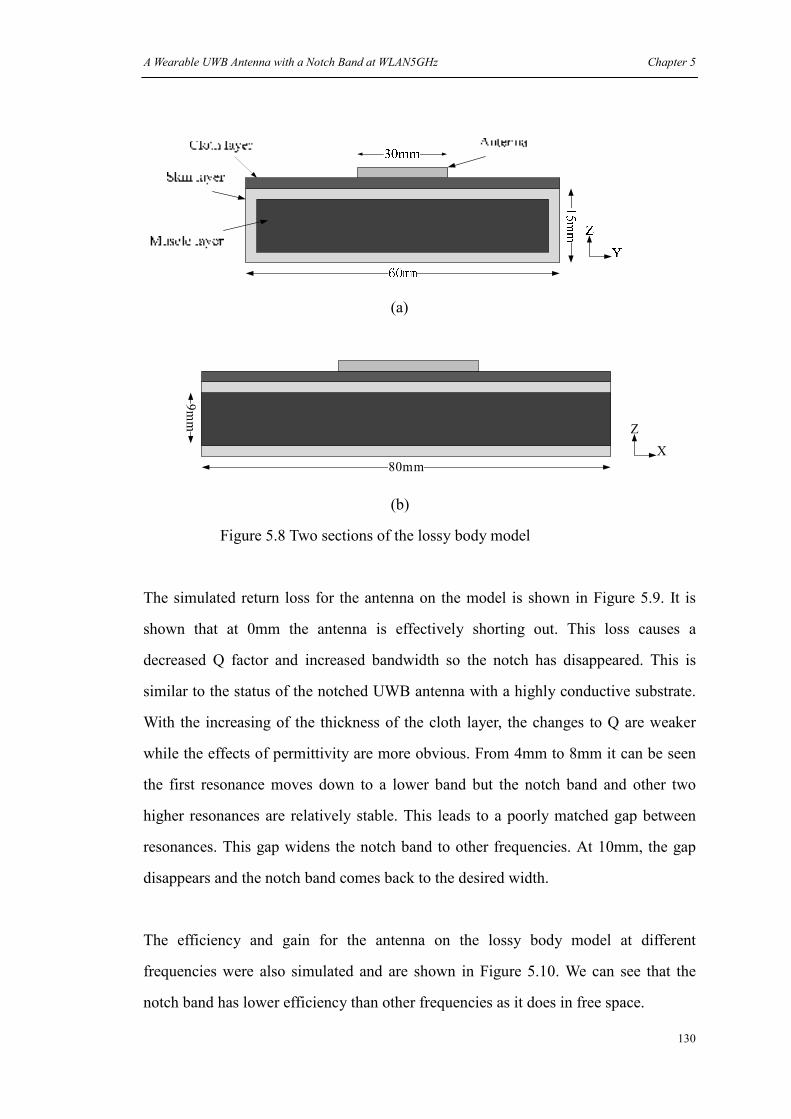
A Wearable UWB Antenna with a Notch Band at WLAN5GHz Chapter 5
130
(a)
80mm
X
Z
9m
m
40mm
(b)
Figure 5.8 Two sections of the lossy body model
The simulated return loss for the antenna on the model is shown in Figure 5.9. It is
shown that at 0mm the antenna is effectively shorting out. This loss causes a
decreased Q factor and increased bandwidth so the notch has disappeared. This is
similar to the status of the notched UWB antenna with a highly conductive substrate.
With the increasing of the thickness of the cloth layer, the changes to Q are weaker
while the effects of permittivity are more obvious. From 4mm to 8mm it can be seen
the first resonance moves down to a lower band but the notch band and other two
higher resonances are relatively stable. This leads to a poorly matched gap between
resonances. This gap widens the notch band to other frequencies. At 10mm, the gap
disappears and the notch band comes back to the desired width.
The efficiency and gain for the antenna on the lossy body model at different
frequencies were also simulated and are shown in Figure 5.10. We can see that the
notch band has lower efficiency than other frequencies as it does in free space.

A Wearable UWB Antenna with a Notch Band at WLAN5GHz Chapter 5
131
-60
-50
-40
-30
-20
-10
0
2 3 4 5 6 7 8 9 10 11
Frequency (GHz)
Return Loss (dB)
Free space
0mm
2mm
4mm
6mm
8mm
10mm
Figure 5.9 Simulated return loss for the notched UWB antenna on the lossy body model
versus different thickness cloth layer
-25
-20
-15
-10
-5
0
0 5 10 15 20
Thickness of cloth layer (mm)
Antenna Efficiency (dB)
4GHz
5.8GHz
8GHz
(a)

A Wearable UWB Antenna with a Notch Band at WLAN5GHz Chapter 5
132
-20
-15
-10
-5
0
5
10
0 2 4 6 8 10 12 14 16 18 20
Thickness of cloth layer (mm)
Gain (dBi)
4GHz
5.8GHz
8GHz
(b)
Figure 5.10 Simulated antenna efficiency and gain for the notched UWB antenna on a
lossy body model at different frequencies
Due to its small size, the wearable notched UWB antenna can be integrated on gloves
and worn on hand. To measure the on hand performance the prototype was sewn onto
a woolen glove with approximately 2.5mm thickness. This is shown in Figure 5.11(a).
For return loss the antenna was first measured in free space, then on the back of the
right hand with the ground plane directly in contact with the skin and finally with the
antenna on back of the glove also worn on the right hand. The position of the hand in
relation to the body was kept as constant as possible and is shown in Figure 5.11(b).
Ferrites were used on the cable to reduce possible stray currents on the cable. Results
in Figure 5.12 show that when directly in contact with the skin of the hand, the
antenna has a reduced performance in terms of return loss as well as the absence of
the frequency cut off. While the isolation effect of the glove is useful for maintaining
a relatively stable return loss and the notch. The notch band has been slightly shifted
down and becomes wider which is similar to the simulations.

A Wearable UWB Antenna with a Notch Band at WLAN5GHz Chapter 5
133
(a) A woolen glove for measurements (b) The position of the hand in relation to
the body for the return loss measurements
Figure 5.11 A glove and body position for the return loss measurements for the notched
UWB antenna on hand
-70
-60
-50
-40
-30
-20
-10
0
2 3 4 5 6 7 8 9 10 11
Frequency (GHz)
Ret
urn
Lo
ss (
dB
)
In free space
Directly mount on the hand
On glove
Figure 5.12 Measured return loss for the notched UWB antenna
in free space and on hand

A Wearable UWB Antenna with a Notch Band at WLAN5GHz Chapter 5
134
To measure representative radiation patterns in an anechoic chamber, the pork leg
joint was used to mimic the effects of a human hand. Before the measurement, the
return loss for the antenna on the pork leg joint was first measured and compared with
the result on the hand. Pork has similar properties to the human body tissue [15] [16].
The results in Figure 5.13 show the return loss of putting on the pork leg joint has a
good agreement with that of putting on the hand. For the on skin radiation pattern
measurement, the antenna was placed directly onto the flesh. For the on-glove
measurement, to simulate the material of the glove a 2.5mm layer of felt was inserted
between the antenna’s ground plane and the flesh. Although monopole antennas show
relatively omni-directional radiation patterns in free space, the main lobe of this
antenna was seen to be away from the flesh due to absorption by the flesh. The results
at 4GHz and 6GHz are shown in Figure 5.14.
-70
-60
-50
-40
-30
-20
-10
0
2 3 4 5 6 7 8 9 10 11
Frequency (GHz)
Ret
urn
Loss
(dB
)
Directly on the hand
With glove on hand
Directly on leg joint
With inserted felt on leg joint
Figure 5.13 Measured return loss for the notched UWB antenna
on a pork leg joint

A Wearable UWB Antenna with a Notch Band at WLAN5GHz Chapter 5
135
4GHz XZ Plane
-40
-30
-20
-10
00°
45°
90°
135°
180°(-180°)
-135°
-90°
-45°
Co-Polar Cross-Polar
4GHz YZ Plane
-40
-30
-20
-10
00°
45°
90°
135°
180°(-180°)
-135°
-90°
-45°
Co-Polar Cross-Polar
(a)
6GHz XZ Plane
-50
-40
-30
-20
-10
00°
45°
90°
135°
180°(-180°)
-135°
-90°
-45°
Co-Polar Cross-Polar
6GHz YZ Plane
-50
-40
-30
-20
-10
00°
45°
90°
135°
180°(-180°)
-135°
-90°
-45°
Co-Polar Cross-Polar
(b)
Figure 5.14 Measured radiation patterns at 4GHz and 6GHz for the notched UWB
antenna on a pork leg joint with 2.5mm felt inserted between
SAR values were measured without and with a 4mm felt layer simulating for gloves at
2.45GHz using the DASY4 SAR measurement kit. When directly mounted on the
back of the phantom, with 10dBm input power, the maximum SAR, SAR 1g and SAR
10g were 2.14W/Kg, 0.73W/Kg and 0.26W/Kg respectively. With a 4mm layer
between the antenna and phantom, these values were reduced to 0.45W/Kg,
0.18W/Kg and 0.08W/Kg respectively.

A Wearable UWB Antenna with a Notch Band at WLAN5GHz Chapter 5
136
5.4 Tuning for the notched UWB antenna on a glove
When first designing the UWB antenna on a glove, the gap between the lowest
resonance and the notch band was not considered. This meant that when worn on the
human body a wider notch than desired would be created due to the effects from the
human body at different frequencies. After tuning, the antenna shown in Figure 5.15
has been shortened in length to move its resonances closer together. In addition, the
notch band has also been adjusted. The simulated return loss for the tuned UWB
antenna on the lossy body model is shown in Figure 5.16. The measured return loss
for the tuned antenna in free space and on back of the glove worn on the right hand is
shown in Figure 5.17. It can be seen from these results that the antenna now has the
desired performance on a glove. It has the property that working at UWB band
without affecting the WLAN5GHz band.
mm3mm9Slot ×
(a) Dimensions of the top side (b) Dimensions of the bottom side

A Wearable UWB Antenna with a Notch Band at WLAN5GHz Chapter 5
137
(c) Prototype of the top side (d) Prototype of the bottom side
Figure 5.15 The dimensions and prototype of the tuned UWB antenna
-60
-50
-40
-30
-20
-10
0
2 3 4 5 6 7 8 9 10 11Frequency (GHz)
Return Loss (dB)
Free space
0mm
2mm
4mm
6mm
8mm
10mm
Figure 5.16 Simulated return loss for the tuned UWB antenna on the lossy body model

A Wearable UWB Antenna with a Notch Band at WLAN5GHz Chapter 5
138
-50
-40
-30
-20
-10
0
2 3 4 5 6 7 8 9 10 11Frequency (GHz)
Return Loss (dB)
In free space
On glove
Figure 5.17 Measured return loss for the tuned UWB antenna
in free space and on back of the glove worn on the right hand
5.5 Conclusions
In this chapter, a wearable UWB antenna with a notch function at WLAN5GHz band
was presented. The method of corner cutting from a square printed monopole was
used to move several resonances closer to cover the UWB band. By adding an
unequal length leg in the centre of the radiating element a notch function was
achieved. In addition to this inserted leg, simulations also showed that two
symmetrical slots beside the central leg were able to affect the position, bandwidth
and magnitude of the notch band. The effects of the varied conductivity of the
substrate on the return loss and efficiency of the notched UWB antenna were also
discussed. It can be seen with a high loss substrate the notch band disappeared in
terms of return loss while it remained a lower efficiency than other frequencies. On
the other hand substrates with higher conductivity may lower efficiency at all
frequencies in the chosen band. This may be germane to fabric substrates which
absorb water and sweat and then become conductive. Therefore the use of a low loss

A Wearable UWB Antenna with a Notch Band at WLAN5GHz Chapter 5
139
and water resistant material is preferred for wearable antennas.
The antenna was then simulated close to a lossy mass model in Microstripes. The
return loss showed that no isolation between the antenna and lossy mass had similar
effects to using the high loss substrates. The working band in terms of return loss was
widened with the notch band reduced and associated low efficiency at all frequencies
in the range. It was then shown that insulating the antenna can be beneficial. A thin
cloth layer (isolation) was seen to reduce the effect of tissue absorption on gain and
efficiency. In addition, from the results of the antenna efficiency and gain, it was seen
that when the cloth layer is thicker than 2mm, the notch band always has lower
efficiency and gain than other frequencies. So we may conclude that the method used
in this chapter to achieve a notch is feasible for wearable applications.
Finally a tuned UWB with a notch was designed and measured. By decreasing the
length of the main radiating element the lowest resonance was moved closer to the
notch band. In addition the notch band was also adjusted to have a narrower
bandwidth. The simulations and measurements show how a tuned antenna can cancel
the effects from human body and have a desired performance on the hand with a
glove.
A Wearable UWB Antenna with a Notch Band at WLAN5GHz Chapter 5
140
References
[1] S. Stroh “Ultra-wideband: Multimedia Unplugged”, IEEE Spectrum, vol. 40, n.9,
Sept. 2003, pp.23-27
[2] E. R. Green, S. Roy, “System Architectures for High-rate Ultra-wideband
Communication Systems: A Review of Recent Developments”, Intel white paper 241,
2004
[3] S. Roy et al., “Ultra-wideband Radio Design: The Promise of High-Speed,
Short-Range Wireless Connectivity”, Proceedings of the IEEE, vol. 92, n. 2, Feb.
2004, pp. 295-311
[4] Gary Breed, "A Summary of FCC Rules for Ultra Wideband communications,"
High Frequency Electronics, January 2005.
[5] IEEE-SA Standards Board, "IEEE STD 802.11a-1999," Oct. 1999.
[6] Yongjin Kim and Do-Hoon Kwon, "Planar ultra wide band slot antenna with
frequency band notch function," Antennas and Propagation Society International
Symposium, 2004. IEEE, vol. 2, pp. 1788-1791 Vol.2, 2004.
[7] A. Kerkhoff and Hao Ling, "A parametric study of band-notched UWB planar
monopole antennas," Antennas and Propagation Society International Symposium,
2004. IEEE, vol. 2, pp. 1768-1771 Vol.2, 2004.
[8] Taeyoung Yang, W. A. Davis and W. L. Stutzman, "Wearable ultra-wideband
half-disk antennas," Antennas and Propagation Society International Symposium,
2005 IEEE, vol. 3A, pp. 500-503 vol. 3A, 2005.
[9] M. Klemm and G. Troester, "Textile UWB Antennas for Wireless Body Area
Networks," Antennas and Propagation, IEEE Transactions on, vol. 54, pp. 3192-3197,
2006.

A Wearable UWB Antenna with a Notch Band at WLAN5GHz Chapter 5
141
[10] Ma, L.; Edwards, R. M.; Whittow, W. G.; “A multi-band printed monopole
antenna”, 3rd European Conference on Antennas and Propagation, 2009. EuCAP
2009, 23-27 March 2009, Page(s):962 – 964
[11] Kihun Chang; Hyungrak Kim; Young Joong Yoon; “Multi-resonance UWB
antenna with improved band notch characteristics”, Antennas and Propagation
Society International Symposium, 2005 IEEE , vol. 3A , 2005 , Page(s): 516 - 519
[12] Low, Z.N.; Cheong, J.H.; Law, C.L.; “Low-cost PCB antenna for UWB
applications”, Antennas and Wireless Propagation Letters, IEEE, Volume: 4, 2005,
Page(s): 237 - 239
[13] Sungtek Kahng; Shin, E.C.; Jang, G.H.; Anguera, J.; Ju, J.H.; Jaehoon Choi; “A
UWB antenna combined with the CRLH metamaterial UWB bandpass filter having
the bandstop at the 5 GHz-band WLAN”, Antennas and Propagation Society
International Symposium, 2009. APSURSI '09. IEEE, 2009 , Page(s): 1 – 4
[14] Ye, L.-H.; Chu, Q.-X.; “Improved band-notched UWB slot antenna”, Electronics
Letters, 2009, Page(s): 1283 - 1285
[15] Jung-Mu Kim; Dong Hoon Oh; Jae-Hyoung Park; Jei-Won Cho; Youngwoo
Kwon; Changyul Cheon; Yong-Kweon Kim; "Permittivity measurement for biological
application using micromachined probe", Microwave Symposium Digest, IEEE MTT-S
International, 2005
[16] Garton, A.J.; Land, D.V.; "Dielectric tissue measurements using a co-axial probe
with a quarter-wave choke", IEE Colloquium on Application of Microwaves in
Medicine, Page(s): 10/1 - 10/6, 1995

142
Chapter 6
Conclusions and Future Works
6.1 Conclusions
The work described in this thesis was motivated by the increasing need for flexible,
light weight and low cost wearable antennas to sustain the rapidly growing market of
body-centric electronic systems. Wearable printed monopole designs and their
performance on the human body were the main theme in this thesis.
The research was begun with a thorough review of the properties of the human body
and their possible effects on wearable antennas. The human body is a complex
medium which contains various tissues with different properties. It was shown in
section 2.5 that when the body is located in the near field of a wearable antenna, it
results in the same effects as those for a lossy substrate. This changes both Q and
match for antennas. To calculate the coupling effects, the Method of Moment (MoM)
which is a well known method for computing the current distributions on the antennas
was used. By dividing the body into small elements and using the Electric Field
Integral Equation (EFIE) for the induced electric field inside the tissue and Hallén’s
Integral Equation (HIE) for the antenna current distribution with mutual coupling
terms, the current distributions on the antenna and inside the body can be obtained.
For the first time the water resistant material neoprene was presented for wearable
antenna applications. Neoprene was invented by DuPont® in the 1930s and now has
been widely used to make gloves, cable covers, and gaskets. It is also an important
material for clothing worn by divers, cyclists and surfers. It is flexible and can be
made to have a smooth surface. Neoprene is durable, and resistant to water, oils, heat

Conclusions and Future Works Chapter 6
143
and solvents.
Textiles commonly used by WAs suffer somewhat from trapped air which may have
variable electrical characteristics due to water content. So textiles show unstable
performance when they absorb water. Antennas with such substrates usually have a
lower resonant frequency and narrow bandwidth [18]. In addition, most textiles tend
to have low relative permittivity (<2), while neoprene usually has a permittivity
greater than 4 which is helpful to miniaturize antenna dimensions. It is seen then that
neoprene has many of the desirable properties needed in the fabrication of wearable
antennas. As the substrate, it makes the types of wearable antennas researched here
especially suitable for sports purposes.
At start a study of the dimension effects of the ground plane on printed monopoles
was undertaken. It was shown that using a small ground plane was an efficient way to
reduce the whole size of the printed monopoles but with some cost to impedance
match. Therefore the novel addition of “wings” was made to compensate for the
negative effects of narrow ground planes. By introducing a pair of wings on the
ground plane, associating with different size of the ground plane the input impedance
was adjusted to achieve a better matching without increasing the antenna’s volume.
From the results of chapters 3 and 4 the wings were proved as an efficient tool to
adjust the impedance of printed monopoles.
To further reduce the antenna’s size meander lines were used. This was implemented
with a set of 433MHz meander monopoles. Later this method was used in the design
of a novel multi-band printed monopole design to achieve 900MHz resonance. Thus a
six band antenna was created using only one antenna element.
As previously published for UWB applications, a square monopole with two corners
cut off was replicated. To prevent such type antennas interfering with WLAN5GHz
applications, a novel third leg was inserted into the design to create a notch. From the

Conclusions and Future Works Chapter 6
144
simulated and measured results it was found anti-phase currents were generated along
the leg and slots. Variation of notch function via varied conductance of a substrate was
also examined. It was shown that with a high loss substrate the notch band
disappeared in terms of return loss while it remained a lower efficiency than other
frequencies. This method to create a notch was proved practical and efficient.
Another emphasis of this research was effects of the body on the wearable printed
monopoles. Studies were made on several antennas. At ISM 433MHz, distance
between the WA and the human body was characterized and shown to be the key
factor for the antenna’s working band. This factor has not previously been used in
return loss optimization. Note that at 433MHz, due to its low efficiency, the antenna is
only suitable for short range communications. For other antennas, it was found their
wide bandwidth which constituted of different resonances together in free space, had a
risk to have a notch band appearing between resonances when worn on human body.
It is because different resonances suffered different impacts from the human body and
were separated more widely when the antennas were close to the human body. The
notch function was found efficient both in free space and on the human body. It had a
lower efficiency at the desired band in most cases.
6.2 Future works and considerations
The limited characterization available for neoprene at microwave frequencies brought
uncertainties to antenna designs and these should be looked at in greater detail.
Besides neoprene, more flexible substrate materials should be explored to apply to
wearable antennas for different environments.
For conductive elements of wearable antennas, the material normally seen in EM
shielding was used. This flexible sheet has good conductivity due to the high copper
component but also has a relatively rigid texture. Other types of flexible conductive
Conclusions and Future Works Chapter 6
145
materials need to be researched. As can been seen in Chapter 1, the conductivity of the
conductive parts of the microstrip antennas have effects on antennas’ performance. To
apply these materials on the printed monopoles we also need to find out how the
difference of conductivities affects the antennas. For some of the antennas researched
here such as the printed monopoles, slots were usually used. A tidy slot edge was
usually hard to achieve using a flexible conductive material. Small threads of this
material may short parts of the design. Future research should consider methods to
ameliorate this drawback.
Compared with microstrip antennas that are supported by a large ground plane, it was
shown that wearable printed monopoles suffer more effects from the body. This is
because the fields generated in the near field couple to the skin. From the obtained
simulation and measurement results in this thesis electrical distance was shown to be
a key factor for both the antennas’ performance and SAR. This was especially true for
low frequencies. To improve the low frequency antennas’ performance, an isolation
which can reflect the radiations from the antennas is preferred. To not significantly
increase the whole size of the antennas, the distance between the antennas and the
isolations should be very small. Artificial Magnetic Conductor (AMC) may be a good
choice for wearable antennas of the type discussed here. In the future, we may
consider making low frequency wearable printed monopoles with incorporated AMC
materials.
In this thesis a microstrip feed which lay the feed line and the ground in two different
planes was used. This is a typical method for printed monopoles. Advantages are easy
build and integration on PCBs. For wearable antennas it was found that this layout led
to asymmetrical radiation in the YZ plane in free space. An alternative feed method is
coplanar waveguide (CPW) feed which lays both the feed line and the ground in the
same plane. This layout has been seen in many areas and can be used to solve the
problems mentioned above so may become a next consideration. Another
consideration is the replacement of the SMA connectors which were used for our

Conclusions and Future Works Chapter 6
146
antenna prototypes. Smaller connectors can be used to further reduce the size of the
wearable antennas.
For SAR measurements a fluid filled glass fiber phantom was used. Unlike the body
glass fiber is non-conductive. It may be possible to design a coating for such
phantoms so that they better resemble properties of skin. The future research may also
have more accurate results to be obtained.

147
Appendix I
Radiation Integrals and Auxiliary
Potential Functions [1]
When knowing a source, say an antenna, to analysis its parameters like radiation
pattern and input impedance, we always introduce auxiliary functions, known as
vector potentials. It is possible to calculate the E and H field directly from the source
densities J and M on the antenna, but we can simplify the procedure when introducing
the auxiliary functions. Magnetic vector potential A and electric vector potential F are
the most commonly used auxiliary functions. The usual procedure to calculate the
radiated fields is shown below
Figure I.1 The procedure for a computing radiated fields
The time-harmonic form of Maxwell’s equations is shown as
∇ × E = ωj− B (I-1a)
∇ × H = ωj D + J (I-1b)
⋅∇ D = ρ (I-1c)
⋅∇ B = 0 (I-1d)
⋅∇ J = ωρj− (I-1e)
D =ε E (I-1f)
B =µ H (I-1g)

Radiation Integrals and Auxiliary Potential Functions Appendix I
148
E: Electric field intensity D: Electric displacement vector
H: Magnetic field intensity B: Magnetic flux
ρ : Charge density J: Current density
ε : Permittivity µ : Permeability
The vector potential A is useful to solve the EM field generated by a given harmonic
electric current J. The magnetic flux B is always solenoidal (I-1d). Because
×∇⋅∇ A = 0 (I-2)
where A is an arbitrary vector, we can define
B A = µ H A = ×∇ A (I-3a)
or
H A = ×∇µ1
A (I-3b)
Substituting (I-1g) and (I-3a) into (I-1a), we can get
×∇ E A = ωj− ×∇ A (I-4a)
or
×∇ (E A + ωj A) = 0 (I-4b)
From the vector identity
×∇ ( eφ∇− ) = 0 (I-5)
we can express E A as

Radiation Integrals and Auxiliary Potential Functions Appendix I
149
E A + ωj A = eφ∇− (I-6)
or
E A = eφ∇− ωj− A (I-7)
where eφ is an arbitrary electric scalar potential which is a function of position.
Taking the curl of both sides of (I-3a), and using the vector identity
×∇×∇ A = ∇ ( ⋅∇ A) 2∇− A (I-8)
we get
×∇ (µ H A ) = ∇ ( ⋅∇ A) 2∇− A (I-9)
For a homogeneous medium, this equation can be reduced to
µ ×∇ H A = ∇ ( ⋅∇ A) 2∇− A (I-10)
Substituting (I-1b) and (I-1f) to (I-10) leads to
µ J + ωµεj E A = ∇ ( ⋅∇ A) 2∇− A (I-11)
Then substituting (I-7) to (I-11) we get
2∇ A+2k A = µ− J + ∇ ( ⋅∇ A) + ∇ ( ejωµεφ )
= µ− J + ∇ ( ⋅∇ A + ejωµεφ ) (I-12)
where µεω 22 =k . Using Lorentz condition, we let

Radiation Integrals and Auxiliary Potential Functions Appendix I
150
⋅∇ A = ejωµεφ− (I-13)
then we can get
eφ = ωµεj
1− ⋅∇ A (I-14)
Now, the E A can be expressed as
E A = eφ∇− ωj− A = ωj− A ωµεj
1− ∇ ( ⋅∇ A) (I-15)
and at the same time we can get H A from (I-3b).
Also we can get
2∇ A+2k A = µ− J (I-16)
where J = J x + J y + J z . If we can derive the solution from the equation (I-16), we
will know E A and HA
.
We first find the solution for a point source, and then we can form a general solution
by viewing an arbitrary source as a collection of point sources. Let us assume that this
point source which is an infinitesimal source with current density J z is placed at the
origin of an x, y, and z coordinate system. So we can rewrite (I-16) as
2∇ A z +2k A z = µ− J z (I-17)
Since the point source is zero everywhere except at the origin, (I-7) becomes
2∇ A z +2k A z = 0 (I-18)

Radiation Integrals and Auxiliary Potential Functions Appendix I
151
Since the source is a point, it requires that A z is not a function of direction θ andφ .
We express (I-8) in a spherical coordinate system, where A z = A z ( r ) and r is he
radial distance from the source
2∇ A z (r) + 2k A z (r) = rr ∂∂
2
1[
r
rr z
∂∂ )(2 A
] + 2k A z ( r ) = 0 (I-19)
The solution is
A z = r
eC
jkr−
(I-20)
In the presence of the source J z , the solution is
A z = ∫−
z
jkr
z dzr
eJ
πµ
4 (I-21)
So the solution of (I-16) is
A = ∫∫∫−
v
jkr
dvr
e'
4J
πµ
(I-22)
If the J is an electric current source I e , and it is not at the origin, the solution will be
line integrals shown as
A = ∫−
c
jkR
e dlR
ezyx '),,(
4I
πµ
(I-23)
where R is the distance from the source ( x’, y’, z’ ) to the observation point (x, y, z)
222 )'()'()'( zzyyxxR −+−+−= (I-24)
Radiation Integrals and Auxiliary Potential Functions Appendix I
152
We can find more details about the computation of F, E F and H F in [1] - [3]. And
now the E and H can be expressed as
E = E A + E F (I-25)
H = H A + H F (I-26)
Radiation Integrals and Auxiliary Potential Functions Appendix I
153
References
[1] Constantine A. Balanis; “Antenna Theory Analysis and Design”, the second
edition, 1998
[2] Warren L. Stutzman, Gary A. Thiele, "Antenna theory and design, the second
edition," John Wiley & Sons, Inc., 1998.
[3] John D. Kraus, "Antennas, the second edition", 1988.
154
Appendix II
The Method of Moment
II.1 Introduction
Antennas are the interface between communication systems and mediums to transmit
and receive radio waves [1]. Understanding the relationship between antennas and
radio waves will help us comprehend the performance of an antenna and improve our
designs. There are three tools available to help us find out those relationships. The
first one is mathematical analysis, the second one is computational electromagnetics
(CEM) and the third one is experimental observation such as the measurement of
antennas [2].
CEM can be subdivided into two categories: numerical methods and high frequency
or asymptotic methods. Numerical techniques are used in the region where the size of
the antenna is on the order of the wavelength to a few tens of wavelengths, while high
frequency methods are suited to the objects that are many wavelengths in extent. For
wearable applications, antennas are usually small in wavelength, so the numerical
methods are our most-used tool. For the convenience and efficiency of the engineers
to solve electromagnetic problems or design antennas and radio circuits, lots of
simulation software using numerical techniques has been schemed out. Such as Ansoft
Designer, IE3D and Microwave Office using Method of Moments (MoM), Ansoft
High-Frequency Structure Simulator (HFSS) using Finite Element Method (FEM),
EMPIRE using Finite Difference Time Domain (FDTD) method and Microstripes
using Transmission Line Matrix (TLM) method, they have been widely used.
In this section we will focus on one of these numerical methods, MoM. We begin with
an introduction of radiation integrals and auxiliary potential functions, following a
brief view of MoM’s theory and then some applications are given in the Appendix.

The Method of Moment Appendix II
155
II.2 The Method of Moment (MoM)
From appendix I we find that once we know the current distribution on an antenna, we
can easily calculate out its E and H field and then other parameters. However in
practice, we are always facing many complicated antennas with unknown current
distribution. To find out these antennas’ performance, people have developed many
numerical methods. MoM is one of them. In this section, we will give a brief view
about MoM and this will help us better understand how numerical methods work.
First let’s consider a wire antenna along the z-axis. A generic form for an integral
equation describing such an antenna is
)(')',()'( zdzzzKz i∫ =− EI (II-1)
The kernel K (z, 'z ) depends on the specific integral equation formulation used.
Electromagnetic radiation problems can always be expressed as such an integral
equation of the general form in (II-1) with an inhomogeneous source term on the right
and the unknown current within the integral. MoM is a solution procedure for
approximating such an integral equation. Once the current distribution is known, it is
fairly straightforward procedure to determine the radiation pattern and impedance.
II.2.1 Pocklington’s Integral Equation
In 1897 Pocklington introduced an integral equation to treat wire antennas. This
equation shows that the current distribution on the thin wires is approximately
sinusoidal and propagates with nearly the speed of light. Assuming we put a wire with
the conductivity σ along the z-axis. If we use copper which has very high σ as the
wire, the current on the wire is confined to the surface. This can be replaced by

The Method of Moment Appendix II
156
another equivalence model where current on the material wire is replaced by an
equivalent surface current in free space. This is shown in Figure II.1.
If the wire radius a is much less than the wavelength, we may assume only z-directed
currents are present. For this wire, the magnetic current density M is zero and the
electric current density is J. Thus from equations (I-15) and (I-24), we can obtain
)(1 2
2
2
zz
z kzj
AA
E +∂∂
=ωεµ
(II -2)
εµσ ,,oo εµ ,
oo εµ , oo εµ ,
Figure II.1 Highly conducting thin wire and its equivalence model along z-axis
From equations (I-21), (II-2) and Figure II.1, if we let
R
ezz
jkR
πψ
4)',(
−
= (II-3)
we can get

The Method of Moment Appendix II
157
')',()',(1
2
2
2
2
2
0
dvzzkz
zz
jE S
c
L
Lz J∫ ∫−
+
∂∂
= ψψ
ωε (II -4)
where )',( zzψ is the free-space Green’s function and c is the cross-sectional curve
of the wire surface. For a<<λ , the current distribution is nearly uniform with respect
toφ ’ and equation (II -4) reduces to a line integral of the total current:
')'()',()',(1
2
2
2
2
2
0
dzzIzzkz
zz
jE
L
Lz ∫−
+
∂∂
= ψψ
ωε (II -5)
If one observes the surface current distribution from a point on the wire’s surface, an
equivalent filamentary line source model shown in Figure II.2.
oo εµ ,
oo εµ ,oo εµ ,
Figure II.2 Theoretical models for a thin wire
We can denote the quantity zE in equation (II -5) as the scattered field S
zE [2]. If
there is an incident or impressed field i
zE , at the surface of the perfectly conducting
wire and also interior to the wire, the sum of the tangential components of the

The Method of Moment Appendix II
158
scattered field and the incident field must be zero, which is the boundary condition of
the perfect metal [12].
)(')'()',()',(1
2
2
2
2
2
0
zdzzzzkz
zz
j
i
z
L
L EI =
+
∂∂−
∫− ψψ
ωε (II -6)
This equation is the type of integral equation derived by Pocklington and is of the
general form used in (II-1)
II.2.2 Integral Equations and Kirchhoff’s Network Equations
For convenience, we write (II-6) in the form
)(')',()'(2
2
zdzzzKz i
z
L
L EI =− ∫− (II -7)
We let
∑=
=N
n
nn zFIz1
)'()'(I (II -8)
where nI ’s are complex expansion coefficients which are unknown and )'(zFn is a
series of known expansion functions. There are many kinds of expansion functions we
can use, such as orthogonal pulse functions, triangle functions (piecewise linear
functions), and piecewise sinusoidal functions. These functions are shown in Figure
II.3.

The Method of Moment Appendix II
159
Figure II.3 Expansion functions
We assume the expansion functions are a set of orthogonal pulse functions given by

The Method of Moment Appendix II
160
otherwise
'∆in 'for
0
1)'(
nzzzFn
= (II -9)
The expansion in terms of pulse functions is a “stair step” approximation to the
current distribution on the wire, where the wire is divided into N segments of
length nz'∆ . Substituting (II-8) to (II-7) gives
)(')',()'(2
2 1
m
i
z
L
L
N
n
mnn zEdzzzKzFI ≈− ∫ ∑− =
(II -10)
where the subscript m on mz indicates that the integral equation is being enforced at
segment m. Substituting (II-9) into (II-10), we get
)(')',(1
'm
i
z
N
nz
mn zEdzzzKIn
≈−∑ ∫=
∆ (II -2)
If we let
∫∆−= nzmnm dzzzKzzf
')',()',( (II -3)
equation (II-11) becomes
)()',(1
m
i
z
N
n
nmn zEzzfI ≈∑=
(II -4)
A physical interpretation of this equation is “The wire has been divided up into N
segments, each of length 'z'n z∆=∆ , with he current being an unknown constant over
each segment. At the center of the mth segment, the sum of the scattered fields from
all N segments is set equal to the incident field at the point mz . The incident field is a
known field arising from either a source located on the wire(transmitting case) or
from a source located at a large distance(receiving case or radar scattering case) ” [2].

The Method of Moment Appendix II
161
If we want a more accurate representation of I (z’), shorter segments (and a larger N)
are needed. This is shown in Figure II.4.
Figure II.4 Point-matching
We know Kirchhoff’s network equation has the form:
m
N
n
nmn VIZ =∑=1
m=1, 2, 3 … N (II -5)
which shows the resemblance with equation (II-13). If we let
)',( nmmn zzfZ = (II -6)
and
)( m
i
zm zEV = (II -16)
equation (II-13) is changed to (II-14), which means we can solve the integral equation
(II-7) numerically by the same way as solving the circuit problem.
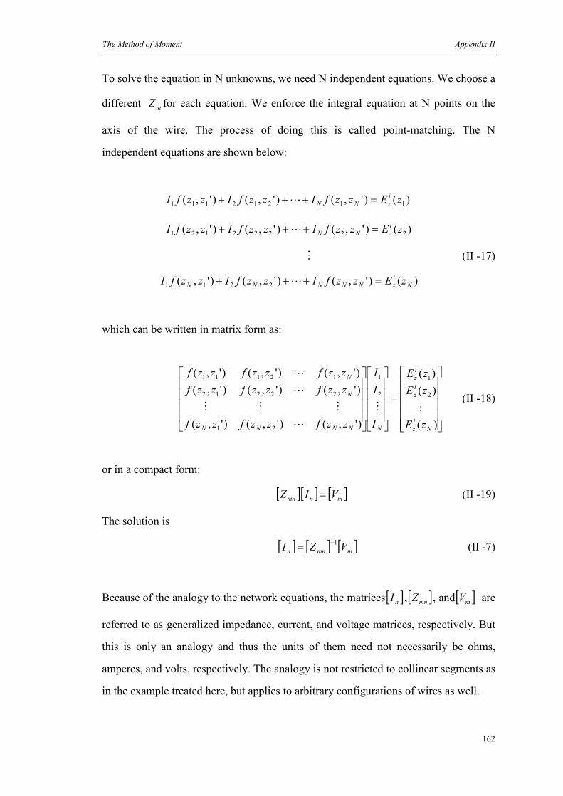
The Method of Moment Appendix II
162
To solve the equation in N unknowns, we need N independent equations. We choose a
different mZ for each equation. We enforce the integral equation at N points on the
axis of the wire. The process of doing this is called point-matching. The N
independent equations are shown below:
)()',()',()',( 11212111 zEzzfIzzfIzzfI i
zNN =+++ L
)()',()',()',( 22222121 zEzzfIzzfIzzfI i
zNN =+++ L
M (II -17)
)()',()',()',( 2211 N
i
zNNNNN zEzzfIzzfIzzfI =+++ L
which can be written in matrix form as:
=
)(
)(
)(
)',()',()',(
)',()',()',(
)',()',()',(
2
1
2
1
21
22212
12111
N
i
z
i
z
i
z
NNNNN
N
N
zE
zE
zE
I
I
I
zzfzzfzzf
zzfzzfzzf
zzfzzfzzf
MM
L
MMM
L
L
(II -18)
or in a compact form:
[ ][ ] [ ]mnmn VIZ = (II -19)
The solution is
[ ] [ ] [ ]mmnn VZI1−= (II -7)
Because of the analogy to the network equations, the matrices [ ]nI , [ ]mnZ , and [ ]mV are
referred to as generalized impedance, current, and voltage matrices, respectively. But
this is only an analogy and thus the units of them need not necessarily be ohms,
amperes, and volts, respectively. The analogy is not restricted to collinear segments as
in the example treated here, but applies to arbitrary configurations of wires as well.

The Method of Moment Appendix II
163
II.2.3 Source modeling
The most used generator model in wire antenna theory is the delta gap model, shown
in Figure II.5. Although such sources do not exist in practice, they do provide good
approximation.
This source is from the assumption that a voltage is placed across the gap, giving rise
to an impressed electric field δ/Ai VE = confined entirely to the gap (i.e., no
fringing.)The voltage across the gap is determined by the line integral of the electric
field across the gap.
δ
2
AV
2
AV−
iE
Figure II.5 The delta gap source model with impressed field δ/Ai VE =
Actually point-matching is just a special case in the method of moment. But it is a
very useful approach to solve simple wire antennas, and give us good approximation.
More general procedure of moment method can be found in [2][3].

The Method of Moment Appendix II
164
References
[1] Fawwaz T. Ulaby, "Fundamentals of Applied Electromagnetics," Prentice Hall,
Upper Saddle River, New Jersey, 2001.
[2] Warren L. Stutzman, Gary A. Thiele, "Antenna theory and design, the second
edition," John Wiley & Sons, Inc., 1998.
[3] John D. Kraus, "Antennas, the second edition," 1988.

165
Appendix III
Hallén’s Integral Equation
Similar to Pocklington’s Integral Equation, Hallén’s Integral Equation (HIE) assumes
the length of the wire antenna is much larger than its radius so only z-directed currents
are present, which is shown in Figure II.2. According to (I-21) only A z will be
considered. Substituting A z into (I-15) we can get
+−=
∂∂
−−= zzz
z
t
z Adz
Adj
z
AjAjE εω
ωµεωµεω 2
2
2
2
211
(III-1)
where t
zE is the total tangential electric field on the wire. According to the boundary
condition, t
zE equals to zero. So (III-1) can be reduced to
02
2
2
=+ zz Ak
dz
Ad (III-2)
Due to the symmetry of the current density J z along the wire where )'()'( zJzJ zz −= ,
the potential zA is also symmetrical. So the solution of (III-2) is given by
[ ])sin()cos( 11 zkCkzBjAz +−= µε (III-3)
If a voltage iV is used to feed the wire antenna, it is shown that 2/1 iVC = . 1B can
be obtained by applying the boundary condition that the current equals to zero at the
ends of the wire. Equation (III-3) is the HIE for a perfectly conducting wire antenna.