on-board software reference architecture (osra ... · um passo em frente na harmonizac¸ao da...
TRANSCRIPT

On-board Software Reference Architecture (OSRA)Development Analysis
André Filipe Gonçalves Pereira
Thesis to obtain the Master of Science Degree in
Aerospace Engineering
Supervisor(s): Prof. Agostinho Rui Alves da Fonseca
Examination Committee
Chairperson: Prof. Filipe Szolnoky Ramos Pinto CunhaSupervisor: Prof. Agostinho Rui Alves da Fonseca
Member of the Committee: Prof. José Raúl Carreira Azinheira
November 2016

ii

Dedicated to my beloved family and friends.
iii

iv

Acknowledgments
I would first like to thank the Engineer Daniel Silveira for the opportunity to work on very interesting
topics, strongly tied with industrial needs, at GMV, for his valuable help and guidance along the way, and
also for the indispensable support with more technical issues. His immense knowledge and expertise
were paramount to steer this work. I must also thank my colleagues at GMV, Guilherme Sanches and
Mario Duarte, for their technical support and fruitful insights.
I would further like to express my gratitude to my supervisor, Professor Agostinho Fonseca, for
his guidance and valuable help in the revision of this thesis. His suggestions and experience were
fundamental to improve the quality of this dissertation.
A note of gratefulness must be expressed to all the amazing people that have accompanied me
throughout the last five years, in Lisbon and in Delft. My professors, colleagues and friends without
whom this fantastic journey would not have been the same. I must dedicate a special thank-you to my
mentor, Tiago Freire, for his continuous encouragement, support, and valuable friendship throughout my
years of study.
Finally, I would like to express my very profound gratitude to my beloved parents and to my brother
for their continuous encouragement, support and unconditional love.
v

vi

Resumo
O software embarcado em satelites e naves espaciais esta continuamente a crescer em tamanho e
complexidade. A reducao dos custos e tempo de desenvolvimento tornaram-se assim a principal
preocupacao na industria espacial. As abordagens tradicionais de desenvolvimento baseadas em
programacao manual revelam-se inadequadas para satisfazer as necessidades atuais. Para enfrentar
este problema foi criada uma arquitetura de referencia para padronizar o desenvolvimento de software
embarcado, bem como varias ferramentas para implementar sistemas complexos adotando uma abor-
dagem guiada por modelos e, simultaneamente, para gerar automaticamente codigo executavel com
base nos modelos implementados. O projeto recente VERICOCOS, levado a cabo pela GMV, pretende
criar uma toolchain completa que inclui algumas das ferramentas referidas e ainda integrar maquinas
de estados no processo de desenvolvimento para modelar o comportamento dos sistemas. No entanto,
existe ainda muito espaco para a melhoria e harmonizacao destas ferramentas.
Esta dissertacao realiza uma analise completa a toolchain do projeto VERICOCOS, identificando
erros e limitacoes, e apresenta sugestoes para a melhoria das ferramentas. Para realizar esta analise foi
desenhado e implementado um modelo mockup baseado no sistema Mission Vehicle Manager (MVM)
da nave de reentrada Intermediate Experimental Vehicle (IXV), tanto ao nıvel da avionica como do
software.
Adicionalmente e gerado codigo com base nos modelos implementados e o exercıcio de adapta-lo a
uma plataforma de execucao particionada em tempo e em espaco e realizado com sucesso, dando mais
um passo em frente na harmonizacao da arquitetura de referencia de software embarcado (do ingles
On-board Software Reference Architecture (OSRA)) com o paradigma da avionica modular integrada
(do ingles Integrated Modular Avionics (IMA)). O codigo adaptado foi executado num simulador e um
MVM completamente operacional foi conseguido.
Palavras-chave: Software Embarcado em Satelites e Naves Espaciais, Architectura de Re-
ferencia, Engenharia Guiada por Modelos, Projecto VERICOCOS, Intermediate Experimental Vehicle,
Particionamento em Tempo e em Espaco, Avionica Modular Integrada.
vii

viii

Abstract
Spacecraft On-Board Software (OBSW) is continuously growing in size and complexity. The reduction
in the development cost and schedule became thereby the leading concern within the space industry.
Traditional software development approaches based on manual coding are no longer suitable to satisfy
the actual needs. To tackle this problem a reference architecture was created in order to standardize the
OBSW development process, together with various tools designed to implement complex systems by
adopting a model based approach and to automatically generate executable application code from the
implemented models. The recent VERICOCOS project, carried out by GMV, intends to create a complete
toolchain including some of those tools and also to integrate state machines in the development process
to perform the behavioural modelling of the systems. However, there is a lot of room for the improvement
and harmonization of such tools.
This thesis analyses the full VERICOCOS toolchain, identifying errors and limitations, and presents
various ways of improvement. In order to do that a complete mockup model based on the Mission
Vehicle Manager (MVM) of the Intermediate Experimental Vehicle (IXV) is designed and implemented,
both at avionics and software level.
Additionally, application code is generated and the exercise to adapt it to a time and space partitioned
execution platform is successfully carried out, taking a step further to the harmonization of the On-board
Software Reference Architecture (OSRA) with the Integrated Modular Avionics (IMA) paradigm. The
adapted code was ran in a simulator and a fully operational MVM system was achieved.
Keywords: Spacecraft On-Board Software, Reference Architecture, Model-Driven Engineer-
ing, VERICOCOS Project, Intermediate Experimental Vehicle, Time and Space Partitioning, Integrated
Modular Avionics.
ix

x

Contents
Acknowledgments . . . . . . . . . . . . . . . . . . . . . . . . . . . . . . . . . . . . . . . . . . . v
Resumo . . . . . . . . . . . . . . . . . . . . . . . . . . . . . . . . . . . . . . . . . . . . . . . . . vii
Abstract . . . . . . . . . . . . . . . . . . . . . . . . . . . . . . . . . . . . . . . . . . . . . . . . . ix
List of Tables . . . . . . . . . . . . . . . . . . . . . . . . . . . . . . . . . . . . . . . . . . . . . . xiii
List of Figures . . . . . . . . . . . . . . . . . . . . . . . . . . . . . . . . . . . . . . . . . . . . . xv
List of Code . . . . . . . . . . . . . . . . . . . . . . . . . . . . . . . . . . . . . . . . . . . . . . . xvii
Acronyms . . . . . . . . . . . . . . . . . . . . . . . . . . . . . . . . . . . . . . . . . . . . . . . . xvii
1 Introduction 1
1.1 Motivation . . . . . . . . . . . . . . . . . . . . . . . . . . . . . . . . . . . . . . . . . . . . . 1
1.2 Objectives . . . . . . . . . . . . . . . . . . . . . . . . . . . . . . . . . . . . . . . . . . . . . 2
1.3 Outline . . . . . . . . . . . . . . . . . . . . . . . . . . . . . . . . . . . . . . . . . . . . . . . 3
2 Background 5
2.1 Historical Perspective . . . . . . . . . . . . . . . . . . . . . . . . . . . . . . . . . . . . . . 5
2.2 On-board Software Reference Architecture . . . . . . . . . . . . . . . . . . . . . . . . . . 7
2.3 Component-Based Software Engineering . . . . . . . . . . . . . . . . . . . . . . . . . . . 8
2.4 Model-Driven Engineering . . . . . . . . . . . . . . . . . . . . . . . . . . . . . . . . . . . . 10
2.5 Modelling Languages and Tools . . . . . . . . . . . . . . . . . . . . . . . . . . . . . . . . . 11
2.5.1 UML - Unified Modelling Language . . . . . . . . . . . . . . . . . . . . . . . . . . . 11
2.5.2 AADL - Architecture and Analysis Design Language . . . . . . . . . . . . . . . . . 12
2.5.3 SDL - Specification and Description Language . . . . . . . . . . . . . . . . . . . . 12
2.5.4 MSC - Message Sequence Chart . . . . . . . . . . . . . . . . . . . . . . . . . . . . 12
2.5.5 AAML - Avionics Architecture Modelling Language . . . . . . . . . . . . . . . . . . 12
2.6 Spacecraft On-board Software . . . . . . . . . . . . . . . . . . . . . . . . . . . . . . . . . 13
2.7 Integrated Modular Avionics . . . . . . . . . . . . . . . . . . . . . . . . . . . . . . . . . . . 14
2.7.1 XKY/AIR . . . . . . . . . . . . . . . . . . . . . . . . . . . . . . . . . . . . . . . . . 15
2.7.2 HAIR . . . . . . . . . . . . . . . . . . . . . . . . . . . . . . . . . . . . . . . . . . . 16
2.7.3 Configuima . . . . . . . . . . . . . . . . . . . . . . . . . . . . . . . . . . . . . . . . 16
2.8 IXV - Intermediate Experimental Vehicle . . . . . . . . . . . . . . . . . . . . . . . . . . . . 16
2.8.1 IXV Avionics Architecture . . . . . . . . . . . . . . . . . . . . . . . . . . . . . . . . 17
xi

2.8.2 IXV On-Board Software . . . . . . . . . . . . . . . . . . . . . . . . . . . . . . . . . 17
3 VERICOCOS Project 19
3.1 VERICOCOS Toolchain Architecture . . . . . . . . . . . . . . . . . . . . . . . . . . . . . . 19
3.1.1 System and Avionics Modelling . . . . . . . . . . . . . . . . . . . . . . . . . . . . . 20
3.1.2 Software Modelling . . . . . . . . . . . . . . . . . . . . . . . . . . . . . . . . . . . . 21
3.1.3 TASTE and Code Generation . . . . . . . . . . . . . . . . . . . . . . . . . . . . . . 21
4 Implementation 23
4.1 Avionics System Implementation . . . . . . . . . . . . . . . . . . . . . . . . . . . . . . . . 24
4.2 Software Implementation . . . . . . . . . . . . . . . . . . . . . . . . . . . . . . . . . . . . 24
4.3 Behaviour Modelling . . . . . . . . . . . . . . . . . . . . . . . . . . . . . . . . . . . . . . . 27
4.4 Model Validation . . . . . . . . . . . . . . . . . . . . . . . . . . . . . . . . . . . . . . . . . 28
4.5 Code Generation and Execution . . . . . . . . . . . . . . . . . . . . . . . . . . . . . . . . 29
5 Toolchain Analysis 33
5.1 Identified Errors and Limitations . . . . . . . . . . . . . . . . . . . . . . . . . . . . . . . . . 33
5.2 User Experience . . . . . . . . . . . . . . . . . . . . . . . . . . . . . . . . . . . . . . . . . 36
5.3 Toolchain Improvements . . . . . . . . . . . . . . . . . . . . . . . . . . . . . . . . . . . . . 37
6 Conclusions 39
6.1 Achievements . . . . . . . . . . . . . . . . . . . . . . . . . . . . . . . . . . . . . . . . . . . 39
6.2 Future Work . . . . . . . . . . . . . . . . . . . . . . . . . . . . . . . . . . . . . . . . . . . . 39
Bibliography 41
A Behaviour SDL Diagrams 45
B Generated Code 47
C Adapted Code 49
xii

List of Tables
5.1 Detected errors end limitations in the toolchain (1/3) . . . . . . . . . . . . . . . . . . . . . 34
5.2 Detected errors end limitations in the toolchain (2/3) . . . . . . . . . . . . . . . . . . . . . 35
5.3 Detected errors end limitations in the toolchain (3/3) . . . . . . . . . . . . . . . . . . . . . 36
xiii

xiv

List of Figures
2.1 Component, container and connector scheme on top of the execution platform . . . . . . 9
2.2 The IMA-SP executive composed by a hypervisor and two partitions, each one running its
version of RTEMS . . . . . . . . . . . . . . . . . . . . . . . . . . . . . . . . . . . . . . . . 15
2.3 IXV mission phases . . . . . . . . . . . . . . . . . . . . . . . . . . . . . . . . . . . . . . . 17
3.1 MSC interaction pattern . . . . . . . . . . . . . . . . . . . . . . . . . . . . . . . . . . . . . 20
4.1 Modelling environment provided by Sirius . . . . . . . . . . . . . . . . . . . . . . . . . . . 23
4.2 OSRA Interface Diagram . . . . . . . . . . . . . . . . . . . . . . . . . . . . . . . . . . . . 25
4.3 DoModeOperations Operation NPF Table . . . . . . . . . . . . . . . . . . . . . . . . . . . 26
4.4 Non TSP Component Instance Deployment Table . . . . . . . . . . . . . . . . . . . . . . . 26
4.5 Device Deployment Table . . . . . . . . . . . . . . . . . . . . . . . . . . . . . . . . . . . . 27
4.6 OpenGeode modelling environment . . . . . . . . . . . . . . . . . . . . . . . . . . . . . . 27
4.7 Analysis Engines - available checks . . . . . . . . . . . . . . . . . . . . . . . . . . . . . . 28
4.8 Validation message . . . . . . . . . . . . . . . . . . . . . . . . . . . . . . . . . . . . . . . 29
4.9 MVM application’s simulation with ten partitions running in HAIR Emulator . . . . . . . . . 30
xv

xvi
Acronyms
AADL Architecture and Analysis Design Language
AAML Avionics Architecture Modelling Language
ARINC Aeronautical Radio Incorporated
ASSERT Automated prof-based System and Software Engineering for Real-Time applications
CBSE Component-Based Software Engineering
CONFIGUIMA Graphical Configuration of Integrated Modular Avionics Systems
COrDeT Component Oriented Development Techniques
DSL Domain Specific Language
ESA European Space Agency
HW Hardware
ICD Interface Control Document
IMA Integrated Modular Avionics
IMA-SP Integrated Modular Avionics for Space
IXV Intermediate Experimental Vehicle
MARTE Modelling and Analysis of Real.Time and Embedded systems
MDA Model-Driven Architecture
MDE Model-Driven Engineering
MVM Mission Vehicle Manager
NASA National Aeronautics and Space Administration
NFP Non-Functional Properties
xvii

NGMP Next Generation Microprocessors
OBSW On-Board Software
OMG Object Management Group
OSRA On-Board Software Reference Architecture
PIM Platform-Independent Model
PM Platform Model
POS Partition Operating System
PSM Platform-Specific Model
RA Reference Architecture
RD Requirements Document
RTEMS Real-Time Executive for Multiprocessor System
SAVOIR Space Avionics Open Interface Architecture
SCM Space Component Model
SDD Software Design Document
SDL Specification and Description Language
SW Software
TASTE The ASSERT Set of Tools for Engineering
TSP Time and Space Partitioning
UML Unified Modelling Language
VERICOCOS Verification of Computer Controlled Systems
WCET Worst Case Execution Time
xviii

Chapter 1
Introduction
Software (SW) stands as an efficient and very flexible way to implement functionalities on board a space-
craft. Thereby, the size and complexity of the spacecraft On-Board Software (OBSW) have been highly
increasing in the past decades. Improving efficiency of OBSW development methodologies while in-
creasing functional complexity is a well known challenge and it is one of the keys of competitiveness of
the space industry in the near future.
1.1 Motivation
The size and complexity of spacecraft OBSW is continuously increasing [1]. Moreover, the schedule
for SW development is getting tighter, with the definition of SW requirements being finalized later and
the final version of the SW being expected to be released earlier [2]. This means that traditional SW
development approaches based on manual coding are no longer suitable to satisfy the actual needs.
Despite this observation, very few spacecraft are produced each year, when compared to other
industries, as the automotive industry for example. The direct consequence is a low level of automation
in the development process, which leads to low SW reusability. Current practices of spacecraft OBSW
development, although conforming to the applicable European Cooperation for Space Standardization
(ECSS) standards like ECSS-E-ST-E40C [3] and ECSS-ST-Q80C [4], are rather isolated of each other.
This has led to a situation where OBSW is developed from scratch based on systems specifications and
requirements. This approach is time consuming, costly, subject of human errors and is not flexible to
changes in the mission specification of late consolidation of mission requirements [5].
Notwithstanding, the OBSW is quite similar across different space missions, sharing many capabili-
ties and constraints. Clearly, current practices can be made more efficient if, throughout the whole SW
life cycle, generic functionality and SW architecture can be identified and reused.
A feasible solution to tackle this issue lies in the standardization of a Reference Architecture (RA)
and the use of a component based SW engineering approach, which makes use of a Domain Specific
Language (DSL).
European Space Agency (ESA) has led various activities to improve platform SW development, being
1

the standardization of the On-Board Software Reference Architecture (OSRA) one of the ESA’s core
research activities, under the Component Oriented Development Techniques (COrDeT) studies [5]. As
a result, a tool for the SW architecture design was created, commonly named OSRA Editor, supported
by a component-based modelling language developed under ESA contract [6].
Other studies were conducted to address the modelling of the avionics of the spacecraft. Namely
the Avionics Architecture Modelling Language (AAML) ESA’s study led by GMV 1 [7], which intended to
create a modelling language and respective Editor to design the spacecraft avionics architecture.
More recently, the Verification of Computer Controlled Systems (VERICOCOS) study [6] was initiated
with the objective of fostering the use of state machines to represent SW behavior of ESA’s operational
projects using dedicated languages and tools [8]. It aims at understanding how behavioural modelling
languages, such as the Specification and Description Language (SDL) [9], can efficiently complement
the OSRA and AAML design tools [6]. This project is still ongoing and GMV takes part on the consortium.
Despite all the efforts being made by ESA and other stakeholders, such as GMV, SciSys 2, University
of Padova 3, Astrium satellites 4 and Thales Alenia Space 5, there is still room for the improvement of
these tools and this is what makes this thesis relevant.
Furthermore the short term efforts will be focused in the harmonization of the OSRA and associated
tools with the Integrated Modular Avionics (IMA) paradigm. This thesis takes a step further towards that
ambitious goal.
1.2 Objectives
This thesis is derived from my collaboration with GMV in the scope of the ongoing VERICOCOS project
and aims primarily at analysing the current VERICOCOS toolchain life-cycle in order to identify pitfalls,
ways of improvement and practicability, and secondarily at fostering the harmonization of OSRA with
the IMA concept by adapting the code generated from the models to be deployed in a Time and Space
Partitioning (TSP) platform.
To perform such analysis, the Intermediate Experimental Vehicle (IXV) 6, an ESA experimental sub-
orbital re-entry vehicle, was studied as a basis for the design, implementation and deployment of a
mockup model to be used as a use case. The Software Design Document (SDD), the Interface Control
Document (ICD), and the Requirements Document (RD), as well as most of the UML diagrams of IXV
project were consulted as the major source of technical information.
A mockup model of the Mission Vehicle Manager (MVM), one of the most relevant subsystems of IXV,
was thereby designed and modelled using both the OSRA Editor and the AAML Editor tools, exploring
as many features and capabilities as possible. The OpenGeode tool was used to model the behaviour
of the system, introducing the SW behavioural modelling through the use of state machine diagrams.
1www.gmv.com/en/2www.scisys.co.uk3www.unipd.it/en/4www.space-airbusds.com/en/5www.thalesgroup.com/en/6www.esa.int/Our Activities/Launchers/IXV/Overview
2

This analysis has not been previously done. It is though a requirement for the final acceptance and
validation of the ongoing VERICOCOS project, which clearly presents the relevance of this thesis.
Simultaneously with the modelling of the MVM, I was in charge of writing the VERICOCOS toolchain
user manual [10], providing a set of instructions to operate with the various tools, create new projects
from scratch, and to perform the behaviour modelling.
1.3 Outline
Following this introductory chapter, the chapter 2 will cover the most relevant topics and concepts funda-
mental to a proper understanding of the subsequent chapters, including an overview of the IXV project.
Additionally a historical perspective is given on the past and actual efforts made to improve the OBSW
and avionics architecture development methodologies. Chapter 3 will present an overview of the VERIC-
OCOS project, including the description of the VERICOCOS toolchain. Chapter 4 will provide details on
the actual implementation of the MVM use case, including the behaviour modelling, code generation,
code adaptation to a TSP platform, and finally the system’s execution. In chapter 5 the toolchain lifecycle
will be analysed, presenting the detected errors and identified limitations of the tools. My experience as
a non expert user of modelling tools will be also presented in this chapter, together with the improve-
ments that can be made to enhance the toolchain in order to make it a widely accepted product within
the space industry and other stakeholders to develop space projects in the near future. Finally, chapter
6 will conclude and close this thesis, summarizing its major results and contribution and reasoning about
the future work and open points of this study.
3

4

Chapter 2
Background
This chapter provides background knowledge on the topics and concepts relevant to this study, being
fundamental to a proper understanding of the following chapters.
It begins with a brief overview of the past efforts realized towards the standardization and automation
of OBSW development, together with the actual context.
It is also included an overview of the existing modelling languages and tools for SW development
within the space industry, with a special focus on the languages that are somehow related to the tools
that were used and analysed in this work.
Afterwards a brief insight on the concept of IMA for space is given, together with the presentation of
some related concepts and tools.
Finally it is presented an overview of the project that is used as a baseline for the design and imple-
mentation of the use case, namely the IXV.
2.1 Historical Perspective
Space industry and agencies have recognized already for quite some time the need to raise the level of
standardisation in the space domain. According to the National Aeronautics and Space Administration
(NASA) agency the size of flight SW is growing by a factor of ten every ten years [11]. The industrial
suppliers are being demanded for increasingly complex systems, with spacecraft OBSW providing more
and more functionalities, together with a contraction of the development schedule and a reduction of
time-to-market. The increasing of efficiency and the reduction in the development cost and schedule
became thereby the leading concerns within the space industry and other major stakeholders.
In response to these needs, ESA launched in 2009 a set of activities, resulting in the definition of
an OSRA that is intended to be adopted in as many ESA missions as possible. The initial steps of this
initiative were coordinated by the so called SAVOIR-FAIRE1 working group, comprised of staff members
of ESA, national space agencies, prime contractors and main SW suppliers. The definition of OSRA was
supported by several industrial activities, namely the COrDeT studies. COrDeT-12 aimed the definition
1FAIRE – Fair Architecture and Interface Reference Elaboration2http://www.pnp-software.com/cordet/
5

of a generic architecture for OBSW applications. COrDeT-23 started in September 2010 and finalized
in December 2012 [12]. It was a continuation of the COrDeT and DOMENG (Framework for DOMain
ENGineering) studies [13] and has successfully achieved a preliminary design of the OSRA, a prototype
implementation of the Space Component Model (SCM) metamodel and the associated model editor,
and a prototype toolset to demonstrate the feasibility of the OSRA [14]. The toolset includes a graph-
ical editor, which includes features to manage libraries of components and implements transformation
engines to generate the final executable image [15].
Studies regarding the avionics level were conducted in parallel by the SAVOIR-IMA4 working group
which resulted in the elaboration of the avionics architecture to support TSP at avionics level. More
specifically the Integrated Modular Avionics for Space (IMA-SP) activity, that has investigated the bene-
fits of incorporating the SW partitioning technology, based upon the IMA concept from aeronautics, into
the spacecraft flight SW architecture in terms of improving the reliability of space systems as well as the
efficiency of the SW development and validation processes [16].
Following the COrDeT-2 study, COrDeT-3 started in October 2013 [15]. This study performed the
consolidation of the OSRA, including the first steps for the harmonization with the IMA-SP project. It
produced a consolidated and consistent OSRA specification, resolving the open issues identified in
COrDeT-2. It also defined a complete and consistent metamodel of the component model together
with its complete semantic description, extending the SCM, and provided a prototype tool, the so called
COrDeT-3 graphical editor, commonly just referred as the OSRA Editor, as a proof-of-concept, imple-
menting the component model. For this implementation the COrDeT-2 graphical editor was taken as
a reference, but it was refined and the development environment differs since COrDeT-3 is based on
open-source tools, namely Sirius5, so it can be widely used.
Both the SAVOIR-FAIRE and SAVOIR-IMA working groups are subgroups of Space Avionics Open
Interface Architecture (SAVOIR) group that intends to improve the way that European space community
builds and develops avionics subsystems, by adopting a building block approach that permits to imple-
ment the OBSW from a set of pre-developed and fully compatible building blocks constructed following
a RA [2]. By adopting a standard architecture with common building blocks that can be reused between
missions, the SW development process can be reduced while improving the functionality of the system
and allowing to handle with increasingly more complex missions [17]. SAVOIR has taken inspiration from
the Automotive Open System Architecture (AUTOSAR)6, an open and standardized system architecture
for the automotive industry [2].
M. Panuzio and T. Vardanega , in their paper published in 2010 [18], present the main conceptual
and methodological steps taken by the SAVOIR-FAIRE working group within the creation of a component
model suited for the development of OBSW.
This study was conducted on top of the successes and lessons learned in the Automated prof-based
System and Software Engineering for Real-Time applications (ASSERT) project [19] over the period
3http://cordet.gmv.com/4IMA – Integrated Modular avionics5https://eclipse.org/sirius/6http://www.autosar.org/
6

2004-2007. This project aimed essentially to the definition of a model-based development process for
OBSW.
The ASSERT studies resulted in a set of tools, comprised in the The ASSERT Set of Tools for
Engineering (TASTE)7 toolset, which consists in an open-source toolchain dedicated to the development
of embedded, real-time systems.
Regarding the avionics architecture another study was conducted by GMV (Spain) and Thales Ale-
nia Space (France) from February 2013 to April 2014, the so called AAML study [7], which aimed at
advancing the avionics engineering practices towards a model-based approach. The main achieve-
ments of this study were a complete description of all the analyses of interest for avionics design in the
different phases of development and the definition of the AAML modelling language, which is a DSL, for
the modelling of an avionics system. A DSL is a programming language or specification dedicated to
a particular problem domain, a particular problem representation technique, and/or a particular solution
technique. Therefore, in this case, AAML is a DSL specific for the avionics architecture [20]. Additionally
a prototype implementation of the AAML metamodel and the associated editor, commonly called AAML
Editor, was developed. The SCM adopted by the OSRA served as the inspiration for this implementation,
thereby guaranteeing compliance between the two approaches [7].
There are still ongoing efforts in the space industry to standardize the development of space avionics,
concerning both Hardware (HW) and SW, focusing on the reduction of development’s time and cost.
Among these endeavours, the improvement and merging of existing tools for OBSW development is
receiving today a special focus, hand in hand with the augmentation of automated code generation
capabilities. This thesis is intended to contribute for the analysis and improvement of some of these
tools, thereby highlighting its pertinence in the context of the ongoing efforts within the space industry.
2.2 On-board Software Reference Architecture
D. Dvorak and K. Reinholtz, in the final report of the NASA study on flight SW complexity [11], wrote the
following about architecture, highlighting its importance within the SW development:
“Architecture is about managing complexity. Good architecture - for both software and hard-
ware - provides helpful abstractions and patterns that promote understanding, solve general
domain problems, and thereby reduce design defects.”
According to the Software Engineering Handbook [21] a Reference Architecture (RA) is a single,
agreed and common solution for the definition of the SW architecture of a set of SW systems whose do-
main of variation is identified. In practice, RA can be understood as a reusable system design pattern,
which assigns the required functionalities of a complex system to a predefined set of composing compo-
nents. In other words the RA essentially dictates the composition of the system in terms of components,
and specifies standardized interfaces between them.
7http://taste.tuxfamily.org/
7

The RA is then used as a basis to develop standards for interface specification, enabling the develop-
ment, by the industry, of building-blocks (see section 2.3) [2]. Furthermore, RAs facilitate standardization
and interoperability of systems within a domain, since they can be design based on the same RA and
therefore follow the same guidelines, standards and principles [22].
Therefore, from a SW architecture perspective, RA represent reusable architecture knowledge in
form of generic artefacts, standards, design guidelines, architectural styles and domain vocabulary [23].
According to the Software Engineering Handbook [21] the success of a RA relies on four fundamental
concepts:
• Separation of concerns: It is the development practice of breaking a computer program into dis-
tinct features that overlap in functionality as little as possible. For example separate the functional
and non-functional concerns of the system, therefore enabling separate reasoning about those
concerns. This separation facilitates both the integration and testing activities.
• Composability: It means the components keep their properties when assembled.
• Compositionality: It means the local properties of assembled components can provide a system
global property.
• Correctness by construction: It is a SW development practice that fosters the early detection
and removal of development errors in order to build safer, cheaper and more reliable SW. It a
priori guarantees the semantic correctness of the user model by strong enforcement of metamodel
constraints.
A typical example for a RA out of the space domain is AUTOSAR, within the automotive industry.
Besides the automotive domain, further applicability of RAs and similar approaches are in Unmanned
Aerial Vehicles (UAV’s), wearable computing and smart homes [22].
The OSRA, specified and implemented as a result of the COrDeT studies, already presented, is then
defined as a single, agreed, and common solution for the definition of the SW architecture of OBSW
systems to be applied in as many ESA’s missions as possible.
This architecture is in line with SAVOIR-FAIRE user needs and requirements, collected in prelim-
inary studies [6], and is sustained by fundamental principles that guide the SW design, namely the
Component-Based Software Engineering (CBSE) and the Model-Driven Engineering (MDE) as SW de-
velopment methodologies that are covered in the following subsections, in addition to the principles of
separation of concerns and correctness by construction already introduced within this section.
Some details from this section were purposefully removed to protect confidential data. In case you
need further information please contact [email protected].
2.3 Component-Based Software Engineering
The RA definition goes hand-in-hand with the concept of CBSE, therefore making sense to briefly explain
this concept. In CBSE, the SW application is composed entirely of SW entities called components, which
8

together with containers and connectors represent the SW entities of the component model. A general
definition of component was given by M. Chaudron and I. Crnkovic in their book [24] as follows:
“A software component is a software building block that conforms to a component model.
A Component Model defines standards for (i) properties that individual components must
satisfy and (ii) methods and possibly mechanisms, for composing components.”
In the context of OSRA, a component is a unit of reuse and it is assumed to have well defined inter-
faces, explicitly captured dependencies and also that it is purely functional, containing only sequential
behaviour with no timing nor synchronisation [25]. A component thereby can be considered to be a
stand-alone service provider, providing a set of functional services exposed through an interface called
provided interface. If the component needs some services from other components or the environment
in general to successfully provide its own services, it gathers these required services through another
interface called required interface. The distinction between a provided and a required interface seems
at a glimpse very obvious but they are commonly confused and interchanged. As a simple remark,
the former describes the services provided by the component, while the latter declares the services a
component will need.
Moreover, components are enveloped by containers, which are responsible for performing the Non-
Functional Properties (NFP) associated with tasking, synchronisation and timing, using the mechanisms
offered by a given execution platform, which, according to [18], consists on the real-time operating
system or kernel, the communication drivers and the board support package for a given HW platform.
The assembling of components into a system is performed connecting the required interface of one
component to the provided interface of other component with a connector. This structure is depicted in
figure 2.1.
Figure 2.1: Component, container and connector scheme on top of the execution platform. [18]
A component is defined by its component type which provides and requires specific interfaces, each
of which is defined by an interface type. To use a component, the component type has to be imple-
mented, creating a component implementation, and then instantiated, creating a component instance
for each use [25].
Finally, all the SW can be deployed on a physical architecture, comprised of computational units,
equipments and network interconnections between them [2].
9

By reusing building-blocks defined by a standard SW architecture, the SW development workload
can be reduced while improving the functionality of the system and mitigating the risk of introducing
errors in the code.
2.4 Model-Driven Engineering
Schmidt in his paper published in 2006 [26] described MDE as a SW development approach that allows
engineers to use high-level abstractions to define components of a SW system throughout the SW
development cycle. In fact MDE emphasizes the creation of SW using models. These are the most
important artefacts in the design of computational systems and are characterized by a high level of
abstraction that intents to increase productivity by reducing programming errors and facilitating the SW
re-factoring
MDE has emerged as a potential breakthrough in the development of complex systems, promising
to considerably reduce the cost of development and time-to-market mainly due to its automation capa-
bilities, alleviating SW complexity by means of models. This allows the developer to abstract away the
implementation details, which are not relevant to the problem domain, and provides an opportunity for
an early verification of the system design [27].
As it is implicit, a model is an abstract representation of the system under development. Models
conform to a metamodel, which describes the syntax of entities that may populate models, as well as
their relationships and the constraints in place between them [28]. In other words a model is nothing
more than an instantiation of a metamodel.
According to Schmidt [26], a promising approach to deal with complexity of platforms is to develop
MDE technologies that combine the following:
• Domain-Specific Modelling Languages (DSML), which capture the specificities of a particular
domain, formalizing its application structure, its behaviour and its requirements. DSML are de-
scribed using metamodels, which define the relationships among concepts in the domain and
specify the key semantics and constraints associated with these concepts.
• Transformation engines and generators, which aim to interpret the information contained in the
model in order to produce various types of artifacts, such as more detailed models, source code,
simulation inputs and even documentation.
Although MDE has best demonstrated its potential in domains like enterprise computing [29], where
it has already been successfully applied, its adoption is less obvious for high-integrity real-time systems,
as it is the case of most of the space systems. In order for MDE to be widely adopted in space domain it
must be proved to be effective in verification and validation, and must cover the extra-functional needs,
which differentiate the high-integrity real-time SW industry from other domains [28].
An example of a standard for MDE approaches is the Model-Driven Architecture (MDA), which was
proposed by the Object Management Group (OMG)8.
8www.omg.org
10

The principle of MDA is to specify system functionality using a Platform-Independent Model (PIM)
which in turn makes use of an appropriate DSL. This PIM generally includes several mode views, typi-
cally the data view, the functional view, and the interface view [30]. Further, this PIM is translated to a
Platform-Specific Model (PSM) that provides a platform specific viewpoint of the system, which typically
consists of a deployment view and a concurrency view, specifying how that system uses a particular
type of platform, taking into account its characteristics. In order to enable this transformation, a Platform
Model (PM) must be provided. The PM includes a set of technical concepts, representing the different
kinds of parts that make up a platform as well as the services it provides [31].
Some details from this section were purposefully removed to protect confidential data. In case you
need further information please contact [email protected].
2.5 Modelling Languages and Tools
Different languages exist to describe a system behaviour as a model. A non-exhaustive list of such
languages is Unified Modelling Language (UML), SysML, MARTE, AADL, AAML, SLIM, SDL, SDL-RT,
Altarica, SCADE, MATLAB, Simulink, CHESS, among others. Within this section a state of the art of
some of these languages is performed. The choice focused on the ones that are directly or indirectly
being used in the scope of the VERICOCOS project for behavioural modelling in the space domain.
2.5.1 UML - Unified Modelling Language
The UML9 is an OMG standard in the SW development area. It represents a general-purpose mod-
elling language with rich graphical notation that allows to model generic SW system architecture and
behaviour. Diagrams are the main concept in UML. It handles structure diagrams, as class and deploy-
ment diagrams, and behaviour diagrams, as activity, sequences and state chart diagrams for example.
The strongest feature of UML is object-oriented modelling. Conversely, there is little support for real-
time modelling and analysis. Intending to overcome this lack of support the OMG adopted the SPT,
the UML profile for Schedulability, Performance and Time. It provides concepts for dealing with model-
based schedulability analysis, performance analysis, and a framework for representing time and time-
related mechanisms. Notwithstanding, this doesn’t bring enough capabilities in terms of its expressive
power and flexibility. It does not capture the complexity of typical analyses in real-time development, like
schedulability and Worst Case Execution Time (WCET) analysis for example [20]. Thereby, STP was
later replaced by Modelling and Analysis of Real.Time and Embedded systems (MARTE)10, which is the
OMG profile for modelling real-time and embedded applications with UML 2.0, the second version of
UML, affording a common way of modelling both HW and SW aspects of a real-time embedded system
during the specification, design, and validation stages. It offers a good support for the modelling plat-
forms and their constituent elements, such as HW resources, as well as the allocation of SW to platform
9http://www.uml.org10http://www.omg.org/omgmarte/
11

entities. Additionally, MARTE focuses on model-based analysis, providing facilities to annotate models
with the information required to perform specific analyses, as performance and schedulability analyses
for example.
The use of UML state machines and sequence diagrams within the space domain requires the defi-
nition of modelling rules and space specific formal semantic [32].
The problem with UML, as many other used modelling languages, has to do with its general purpose
nature. It doesn’t provide abstractions powerful enough to contain all the necessary information within
the model for a specific domain, such as the space domain. The solution envisages the extension of
these languages with behavioural modelling and domain specific concerns
2.5.2 AADL - Architecture and Analysis Design Language
The Architecture and Analysis Design Language (AADL)11 has been designed by the Society of Auto-
motive Engineers (SAE) and aims at modelling systems architecture. It allows the description of both
SW and HW concerns and focuses on the definition of clear block interfaces [33].
2.5.3 SDL - Specification and Description Language
The SDL is a language used mainly in the telecommunication industry. In SDL, each process agent is a
state machine that contributes to the action carried out by the system. A message stimulus coming from
the environment or from another agent is called a signal. Signals received by a process agent are first
placed in a queue (the input port). When the state machine is waiting in a state, if the first signal in the
input port is enabled for that state it starts a transition leading to another state. Transitions can output
signals to other agents or to the environment.
2.5.4 MSC - Message Sequence Chart
A Message Sequence Chart (MSC) is an interaction diagram from the SDL family standardized by the
International Telecommunication Union. MSC can be used in connection with other languages to support
methodologies for system specification, design, simulation, testing, and documentation.
2.5.5 AAML - Avionics Architecture Modelling Language
The AAML modelling language and the AAML toolset were developed in the frame of ESA AAML study
[7]. This activity, started in February 2013 and ended in April 2014, was led by GMV and counted on the
participation of Thales Alenia Space.
In order to support the modelling of the avionics system, it is envisaged a modelling process based
on three levels of definition [7].
• The avionics functional definition is used to design the avionics system as a set of avionic
functions. The avionics functional architecture is a representation of what the avionic system has11http://www.aadl.info/
12

to accomplish for its users. It permits to identify the boundaries of the system, consolidates its
requirements, models functional data exchanges and starts to model the system behaviour.
• The logical architecture definition is a representation of how the system will work in order to fulfil
the requirements and expectations of the users. The logical architecture comprises an allocation
of avionics functions to logical components. It is the level where the first trade-off analysis and
exploration of design space will be performed.
• The physical architecture definition instead is concerned with how the system will be concretely
developed and built. It comprises an allocation of logical components to HW components and a
consolidation of interfaces of each component in their final form.
Some details from this section were purposefully removed to protect confidential data. In case you
need further information please contact [email protected].
Modelling Tools
The presented languages are supported by different tools, such as AAML Editor, OSRA Editor, TASTE,
OpenGeode and MSC Editor, which are described in further detail in section 3.1 since they are part
of the VERICOCOS toolchain. All these tools were developed using the Eclipse Modelling Framework
(EMF)12 to define the DSL, and Sirius13 for the Graphical User Interface (GUI) design.
2.6 Spacecraft On-board Software
OBSW is the SW that is running in the actual spacecraft or satellite that is in operation. In essence it runs
as isolated and independent SW that controls everything on the platform, from propulsion to sensors to
a specialized payload to the power system. It is characterized by its real-time properties. Real-time does
not necessarily means a quick reaction but it does mean to guarantee a reaction inside a certain time
window. Real-time systems can be classified in two categories: Hard real-time system and soft real-time
system. The former represents systems that will have one or more critical failures if any time constraint
is not fulfilled, for example a late completion of a task. On the other hand, the later represents systems
that can continue their execution despite some time requirements are missed. Hard real-time systems
are commonly found interacting with the environment, such as most of the spacecraft systems.
In the realm of real-time systems there are some important concepts that shall be highlighted [34]:
• Deadline is the maximal time instant at which a task must provide its results, i.e. the system must
finish the execution of a given algorithm within a maximal time limit. Deadlines are key issues in
hard real-time systems.
• Worst Case Execution Time (WCET) is the maximal time spent for an algorithm to finish its
execution and deliver the computer results.
12https://www.eclipse.org/modeling/emf/13https://www.eclipse.org/sirius/
13

• Period is the time interval between two consecutive executions of an activity. Predictability is a
key characteristic for real-time systems because their behaviour must be known. Latency and jitter
must be guaranteed within a known maximal time interval.
• Latency indicates the time spent from the stimulus detection until the execution of the code re-
sponsible to handle that stimulus.
• Jitter is a random variation in the timing of a signal, specially a clock.
• Exception handling is what can be done to overcome the problems caused by deadline misses,
or unexpected latency or jitter. Corrective actions are performed to alleviate or even to eliminate
the effects of a temporal failure.
Space Environment
Concerning the environment, a spacecraft is affected by physical conditions in space which go far beyond
the well-known environmental requirements on Earth. These conditions include typically high vacuum,
short-wave solar radiation, ultraviolet X-rays and gamma radiation from the galactic background, high-
energy particles, the cold background of space, microgravity, aerodynamic drag of the atmosphere at
low Earth orbits, and the influence of atomic oxygen [35]. These conditions must be considered not
only during the design and realization of the spacecraft structures, but also during the design of the HW
systems and the development of SW running in these systems.
2.7 Integrated Modular Avionics
The IMA concept emerged as an opposing concept to the federated architecture, and offered the pos-
sibility of integrating multiple functions into the same set of physical resources, allowing the aeronau-
tical industry to manage the SW growth in functionality and in efficiency [36]. IMA identifies the set of
resources that are common to almost all on-board functions and provides a shared resource pool com-
posed by processing, power, communications, and input and output modules that are partitioned for use
in multiple avionic functions. Partitioning keeps applications from inadvertently influencing each other by
enforcing strict separation, segregating computing resources in space and time.
To achieve this high level of integration between applications IMA foresees the use of a time and
space partitioned platform whose architecture was standardized in an effort across all major players in
the aviation industry resulting in the Aeronautical Radio Incorporated (ARINC) specification 653 [37],
which also defines a standard interface between the SW applications and the underlying operating
system.
IMA has already been successfully applied in the development of several aircrafts, most noticeably in
A380 and Boeing 787 [38]. The Airbus and Boeing programs reported savings in terms of mass, power
and volume of 25%, 50% and 60% respectively [39].
Driven essentially by the need to manage the growth in complexity of OBSW the architectural concept
of IMA was transposed from the aeronautical to the space domain. This endeavour was taken by ESA
and other agents of the European space industry.
14

J. Windsor and K. Hjortnaes in their study on TSP in spacecraft avionics [36] described the benefits
of incorporating SW TSP, based upon the aeronautic IMA concept, into the spacecraft avionics architec-
ture to manage the growth of mission functions implemented in the OBSW. Among these benefits the
reduced integration effort, the HW resource savings, and the security stand out.
SAVOIR included a specific subgroup for IMA named SAVOIR-IMA, created to support and manage
the transposition of IMA to space systems. Its mission is to extend the avionics architecture to support
TSP. This working group is focused on IMA architectures and related interfaces to allow the implemen-
tation of interface standards and HW/SW building blocks to fulfil the objectives of the SAVOIR initiative.
GMV had a major role on the outcome of some key activities within this subgroup, contributing in the
definition of an IMA architecture tailored for space systems in the so called IMA-SP activity.
Each application can implement a system function by running several tasks managed by the Par-
tition Operating System (POS), which is modified to operate along with the underlying hypervisor. In
the context of IMA-SP, the selected POS was the space qualified version of the Real-Time Executive
for Multiprocessor System (RTEMS). A graphical representation of an IMA-SP executive is depicted in
Figure 2.2.
Figure 2.2: The IMA-SP executive composed by a hypervisor and two partitions, each one running its
version of RTEMS. [40]
Some details from this section were purposefully removed to protect confidential data. In case you
need further information please contact [email protected].
2.7.1 XKY/AIR
The hypervisors are key players for the implementation of IMA-SP compliant architectures. GMV devel-
oped XKY hypervisor, also known as ARINC Interface in RTEMS (AIR) separation kernel, an ARINC 653
compliant time and space partitioned operating system that was originally based on RTEMS technology
[41].
XKY implements an ARINC 653 compatible architecture by making use of virtualization techniques,
following a two level architecture as already presented, and is currently multi-core aware, supporting the
15

Next Generation Microprocessors (NGMP) processors. For further details about the architecture please
refer to [42].
2.7.2 HAIR
GMV also developed Hypervisor Emulator based AIR (HAIR), whose outcome is a performing and rep-
resentative emulator, in SW and HW, for future CPUs (NGMP) implementing the TSP paradigm in mul-
ticore. For further details about the system please refer to [43].
Furthermore a tool named HAIRDRESSER was created whose functionality is to automatically con-
figure and run an OBSW in HAIR.
2.7.3 Configuima
The Graphical Configuration of Integrated Modular Avionics Systems (CONFIGUIMA) is a graphical
Eclipse based tool designed to support the definition and verification of ARINC 653 modules configura-
tion.
The tool was originally designed to address several past projects partners’ difficulties in defining the
ARINC 653 configuration. It allows the user to specify in a graphical environment the most important
aspects of an IMA configuration, namely the number of partitions and their properties, the inter-partition
communication, by means of partition ports and connections, and also the schedule policy. Afterwards
the configuration can be exported to a .xml file.
This configuration file specifies partitions in terms of memory requirements, communication ports
used, and schedule windows in the major time frame. Multiple modules schedules and health monitor
tables are also specified through the module configuration. The current version of the tool can produce
configuration files for GMV’s AIR operating system, among others.
2.8 IXV - Intermediate Experimental Vehicle
The IXV is an ESA experimental suborbital re-entry vehicle conceived as the step forward from the
successful Atmospheric Re-entry Demonstrator (ARD) [44] to demonstrate re-entry capabilities [45].
The main goal was to design, develop and to perform an in-flight verification of an autonomous lifting
and aerodynamically controlled re-entry system [46].
The mission was designed to accomplish sequentially five main phases named Ascent, Orbital,
Reentry, Descent and Sea-landing. These mission phases are depicted in the figure 2.3.
The IXV was successfully launched on 11th February, 2015 atop the Vega launcher as part of the
VV04 mission being the first ever lifting body to perform full atmospheric re-entry from orbital speed
[47, 48].
It was injected into a suborbital trajectory with a maximum altitude of 413 km, providing a velocity of
7.5 km/s and a flight path angle of 1.16 degrees at the atmospheric entry point, fully representative from
Low Earth Orbit (LEO) missions.
16

Figure 2.3: IXV mission phases (Credits: ESA)
2.8.1 IXV Avionics Architecture
The content from this section was purposefully removed to protect confidential data. In case you need
further information please contact [email protected].
2.8.2 IXV On-Board Software
The content from this section was purposefully removed to protect confidential data. In case you need
further information please contact [email protected].
Summary
In this section an overview of the IXV system was performed. After the complete study and perception
of all the subsystems of IVX, the MVM was selected to be the basis to design and implement a mockup
model to serve as the use case for the intended analysis. The reason behind this choice lies in the fact
that the MVM is the system from which the company has more documentation. All the UML diagrams
and source code from the MVM of IXV were analysed in order to design a mockup model with as much
detail as possible. Notwithstanding one shall not focus on the details of the implementation, but on the
analysis performed with respect to the tools, since this is the very purpose of this study.
17

18

Chapter 3
VERICOCOS Project
The VERICOCOS project aims at fostering the use of state machines to represent SW behaviour of
ESA operational projects using dedicated languages and tools. It is desired a complete toolchain for
the modelling of both SW and avionics of space projects, from the very basics of the architecture to the
representation of the model behaviour with state machines, including the code and document generation
capabilities, and also the possibility of performing analyses to check the model. Its conception comprises
four main distinct phases.
This thesis is mainly a contribution to the second and third phases of the VERICOCOS project.
3.1 VERICOCOS Toolchain Architecture
Resuming the first phase of the study the following tools were selected:
OpenGeode
This tool has been developed by ESA as part of TASTE, and is able to create state machine diagrams
using part of SDL-92 and SDL-2000 language definitions. OpenGeode has been selected as the tool
for managing the state machines on all modelling levels, so the behaviour of the different models is
represented as SDL state machines.
MSC Editor
This tool is also part of TASTE, and consists in a graphical editor of sequence diagrams following the
MSC specification. The MSC Editor has been selected as the tool for working with scenarios on the dif-
ferent modelling levels. Figure 3.1 shows an example of a MSC interaction pattern in which a consumer
makes a request for a service, equivalent to a function call, and the provider provides the response after
a certain time interval.
19

Figure 3.1: MSC interaction pattern. [25]
AAML Editor
This tool has been developed in the frame of ESA’s AAML study. The study was intended to create a
tool for designing avionic architectures and to allow the execution of analyses to refine and verify those
architectures. The editor is based on a metamodel that supports the modelling process and that is used
by the analyses in order to process the design and obtain the suitable data. The AAML Editor was
selected as the tool for modelling the system and avionics levels of the spacecraft.
OSRA Editor
This tool is based on SCM, a domain specific metamodel that allows to describe the architecture of
OBSWs, the platform where the designed OBSW executes, and a set of non-functional characteristics.
The OSRA Editor has been chosen to model the architectural design of the OBSW, while the behaviour
of the SW components should be managed through the OpenGeode tool.
SOIS EDS Reference Toolchain
This tool is produced and owned by ESA for working with the SOIS EDS schemas, and initially devel-
oped under the Adoption of Electronic Data Sheets ESA study [49]. The toolchain will be used for HW
modelling, in addition to OpenGeode for the generation of source code. It is not included yet in the
VERICOCOS toolchain, but its inclusion is in the list of the future work to be done by the working group.
The following sections describe the basic architecture of each different toolset, depending on the
modelling level.
3.1.1 System and Avionics Modelling
The content from this section was purposefully removed to protect confidential data. In case you need
further information please contact [email protected].
20

3.1.2 Software Modelling
The content from this section was purposefully removed to protect confidential data. In case you need
further information please contact [email protected].
3.1.3 TASTE and Code Generation
The content from this section was purposefully removed to protect confidential data. In case you need
further information please contact [email protected].
21

22

Chapter 4
Implementation
This chapter presents the actual implementation of the MVM use case using various tools of the toolchain.
As it was mentioned in the previous chapter, AAML Editor was selected as the most suitable tool for the
avionics architecture design while OSRA Editor was selected to develop the OBSW of the system. Both
tools have many commonalities since both of them were developed by GMV in the frame of two different
ESA projects. The same technologies were used for the development of both tools in order to be able to
integrate them in the future.
The modelling environment is depicted in the figure 4.1 and can be decomposed as follows:
Figure 4.1: Modelling environment provided by Sirius
• 1 - Model Explorer: In the model explorer the user can navigate throughout the whole project,
23

create new elements or delete undesired ones. It is organized in a structured way, conforming to
the metamodel, in order to be easy to find some element. It contains a folder for each individual
project.
• 2 - Workspace: This is where the actual modelling is performed. In the initially empty workspace
the designer or developer starts to create its model by placing in it a set of existing elements
available in the palette.
• 3 - Palette: This is the repository of the existing elements to create the diagram. Each different
diagram has its own set of elements available in the palette and the properties of each element
can be further modified.
• 4 - Properties Spacer: This is where the designer defines the properties of each element inserted
in the diagram. These properties vary from appearance to semantic of the element, including its
name. All the entries shall be filled in order to correctly create the model.
In AAML Editor the designer shall detail all the HW elements and then specify just those SW com-
ponents needed to execute the memory and CPU analyses. On the other hand, in OSRA Editor the
developer shall detail all the SW components together with their NFP and then specify just the HW
elements needed for the code generation.
In this chapter I present some of the diagrams and tables that resulted from my implementation of
the MVM system use case in both levels, namely avionics and OBSW.
Additionally, it is explained the behaviour modelling of the OBSW components. A detailed explanation
of how these diagrams can be created is explained in the User Manual [10] produced in the scope of my
work within the VERICOCOS project.
4.1 Avionics System Implementation
The implementation of the avionics system started with the avionics functional definition since it rep-
resents the highest level of the system’s definition. This functional view is useful for the designer to
diagram the system in a high level of abstraction, before entering in specific details of the actual imple-
mentation itself. This level was idealised to be carried out by the avionics engineers, whom leave the
implementation details to the SW engineers.
The content from this section was purposefully removed to protect confidential data. In case you
need further information please contact [email protected].
4.2 Software Implementation
According to the OSRA Editor design workflow the implementation of the OBSW shall start with the
definition of the data types, exception types, interfaces, together with the respective operations and
attributes, events, and data set specifications. The created Interface Diagram is depicted in figure 4.2,
24

containing a subset of operations exclusive from the SW implementation.
Figure 4.2: OSRA Interface Diagram
The data types created in the OSRA Editor coincide with the ones created in the AAML Editor, due to
the many commonalities that both tools share for the reasons already explained. The same may happen
with the interfaces definition, in which one can observe that most of the interfaces are shared between
tools. This repetition of the definition may be very time consuming when the complexity of the system
increases.
After the data types and interfaces definition the OBSW architecture was designed conforming to
the OSRA component model, which means that the definition of the component types came first, then
the definitions of component implementations, for example in two different languages, and finally the
definition of component instances. The design of the components follows an MDA approach by being
independent from the platform where they are deployed.
Some diagrams and figures from this section were purposefully removed to protect confidential data.
In case you need further information please contact [email protected].
At this point the NFP of the system were specified, such as the NFP of each defined operation
of a provided interface, or the sequence of such operations. As an example the DoModeOperations
Operation NPF Table is depicted in figure 4.3.
25

Figure 4.3: DoModeOperations Operation NPF Table
The next step was the definition of the HW in order to conduct the system deployment. The created
HW diagram is similar to the one obtained in the avionics system implementation, hence not included
in this section. Once again it would be advantageous if the physical diagram already created in AAML
Editor could be imported. The properties of the HW elements were further specified, however in less
detail than in the previous implementation.
Finally all the instantiated components, devices and bindings were deployed onto the respective HW
elements. As an example the Component Instance Deployment Table is shown in figure 4.4 and the
Device Deployment Table is shown in figure 4.5.
Figure 4.4: Non TSP Component Instance Deployment Table
Since there is available only one processor board in the system, it is obvious that all the component
instances have to be deployed on the same unique processor board. A different scenario would be
obtained if it is proven to be advantageous the use of more than one single processor board.
26

Figure 4.5: Device Deployment Table
4.3 Behaviour Modelling
As already seen, the behaviour modelling relies on the creation of state machine diagrams in SDL
language using the OpenGeode tool. The figure 4.6 depicts the modelling environment of such tool. It
includes on the left panel a set of predefined elements that can be used to create the diagram.
Once the OpenGeode is opened from the Component Implementation Diagram within the OSRA Ed-
itor a file containing the information about the data types and the interfaces is automatically loaded. This
way the designer can directly use these elements to communicate and define new internal parameters.
In order to implement an operational MVM system the behaviour of each one of the ten components
that compose the system was thoroughly implemented. The component behaviour SDL diagrams can
be seen in Appendix A.
Figure 4.6: OpenGeode modelling environment
27

Some content from this section was purposefully removed to protect confidential data. In case you
need further information please contact [email protected].
Together the ten diagrams represent the behaviour modelling of the complete system in terms of the
OBSW. These diagrams were then used to generate the source code in C language using the code
generation capabilities of TASTE. An example of such C generated files can be consulted in Appendix
B.
The code generation engine transforms the state machine diagram in a program structured in a
main function called “runTransition” that essentially performs the transition between states. It takes as
input the current state of the state machine, execute all steps described thenceforth and ends with
the transmission of signals to other components that currently correspond to function calls of other
components’ implementations.
These function calls will trigger the other components’ “runTransition” according to the signal inputs
and so on.
4.4 Model Validation
In order to guarantee the compliance of the model with the syntactic and semantic rules of the compo-
nent model a set of different checks were implemented in the COrDeT-3 toolset. These checks were
later extended in the OSRA Editor to also check against the OpenGeode and TASTE toolchain rules.
The OSRA Editor validator against the OpenGeode was improved with my contribution. Some of the
checks were implemented based on the inputs I have given while creating the SDL diagrams referred to
in the previous section.
Additionally it is checked the compliance of the model against the TASTE component model in order
to prevent errors in the code generation. The validation of the user model can be performed running the
Analysis Engines option provided by OSRA Editor, as seen in figure 4.7. Three different checks were
executed.
Figure 4.7: Analysis Engines - available checks
After correcting all the errors and warnings in the model the following message confirmed the cor-
rectness of the model for each check executed.
28

Figure 4.8: Validation message
4.5 Code Generation and Execution
Now that the system behaviour is fully modelled and compliant with the OSRA component model, it
follows the code generation process in order to create the ultimate executables and finally run and test
the designed MVM system. To that end two different approaches were identified. The first one is to
run the Transformation Engines provided by the OSRA Editor and supported by TASTE. These engines
would produce the code skeletons into which the C code generated from each component would be
encapsulated to create the final application ready to be executed on a non TSP execution platform.
The other approach, much more interesting but way more challenging and laborious, is to foster the
integration of the generated C code in a TSP execution platform by adapting the code to a partitioned
system following the IMA-SP paradigm and hence the ARINC 653 standard.
The second hypothesis presents a greater scientific relevance, taking a step towards the harmo-
nization of OSRA with IMA-SP, thus being the one I chose to investigate in order to obtain the final
executables and run the application.
Henceforth the sequence of steps taken from the adaptation of the generated C code to the actual
running of the application will be presented, together with the final obtained results.
IMA Configuration File
Firstly CONFIGUIMA was used to build an IMA configuration XML file compatible with ARINC 653 con-
taining the information about the partitions, the inter-partition communication channels, namely ports
and connections, and also the partitioning schedule. A one-to-one approach between the partitions and
the component instances was adopted in order to benefit as much as possible from TSP. Furthermore
the following simplifications and default approaches were taken:
• The component generated code ran inside a single RTEMS task.
• With no computational model data available, a basic schedule was defined giving an equal execu-
tion time window to all partitions.
The computational model describes how the execution platform manages the processing, communi-
cation, and concurrency of SW dynamic entities in order to fulfil the NFP specified at component level.
Under the TSP execution platform the computational model becomes further complex because it intro-
duces dependencies between tasks deployed to different partitions.
29
Behaviour Code Adaptation
The content from this section was purposefully removed to protect confidential data. In case you need
further information please contact [email protected].
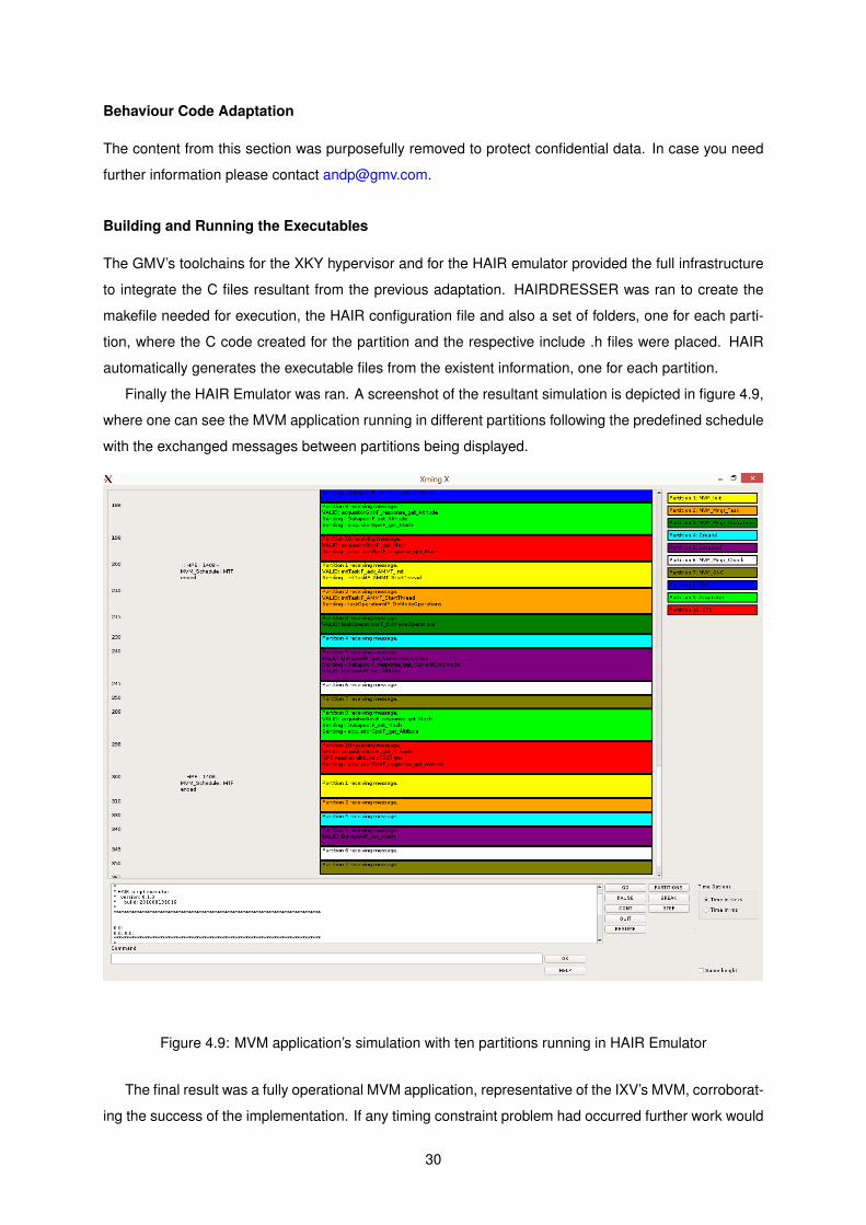
Building and Running the Executables
The GMV’s toolchains for the XKY hypervisor and for the HAIR emulator provided the full infrastructure
to integrate the C files resultant from the previous adaptation. HAIRDRESSER was ran to create the
makefile needed for execution, the HAIR configuration file and also a set of folders, one for each parti-
tion, where the C code created for the partition and the respective include .h files were placed. HAIR
automatically generates the executable files from the existent information, one for each partition.
Finally the HAIR Emulator was ran. A screenshot of the resultant simulation is depicted in figure 4.9,
where one can see the MVM application running in different partitions following the predefined schedule
with the exchanged messages between partitions being displayed.
Figure 4.9: MVM application’s simulation with ten partitions running in HAIR Emulator
The final result was a fully operational MVM application, representative of the IXV’s MVM, corroborat-
ing the success of the implementation. If any timing constraint problem had occurred further work would
30

have been required to optimize the partition schedule or set a specific functionality in an independent
task to improve its availability.
Some details from this section were purposefully removed to protect confidential data. In case you
need further information please contact [email protected].
31

32

Chapter 5
Toolchain Analysis
This chapter derives from the experience I gained as a fresh developer of OBSW using the VERICO-
COS toolchain, and also from the several conversations I had with more expert engineers including my
colleagues and my supervisor. I also took various notes on the ideas and opinions of engineers from
ESA during the meetings in which I have participated. Those notes about the project and its future were
also taken into account to produce the content of this chapter.
5.1 Identified Errors and Limitations
While using the various tools of the toolchain I identified some specific errors or limitations. Those are
presented among tables 5.1, 5.2 and 5.3, together with a possible solution or workaround suggestion
whenever it is applicable. Other minor errors were identified but they were instantly corrected, hence not
included in the tables. The following information is included:
• Error or limitation: Presents a description of the identified error or limitation.
• Tool: Identifies the tools in which the error occurs or where the limitation exists, and also the tools
that are somehow affected by the error or limitation.
• Criticality level: Identifies the criticality level of the error or limitation as follows:
– Low: It is not directly related with the model and possibly does not lead to any error in
validation nor running the transformation engines.
– Medium: It is directly related with the model and causes a validation error or a loss of infor-
mation.
– High: It is directly related with the model and forces the transformation engines to stop run-
ning.
• Workaround: I present in this column a possible workaround to the issue whenever it is applicable.
• Possible solution: I present in this column a possible solution to the problem whenever it is
applicable.
• Solved: It indicates if the problem was already solved by the engineers of GMV-PT or not yet.
33

Error or limitation Tool Criticalitylevel
Workaround Possible solution Solved
Avoid to givesimple namesto the parameterssuch as “state”,“parameter” or“mission” forexample, becausethese are stringsdefined in thelanguage itself,leading to conflicterrors in the model.
OpenGeode Low
The bestpractice isto add aprefix withthe acronymof yourproject toevery singlename yougive to thecreatedvariables,for instance“IXV state”.
N/A N/A
OpenGeode allowsonly one parameterper signal. If theassociatedcomponent definesmore parameters,they all will betransferred toOpenGeode andcause a validationerror.
OpenGeode Medium
The user cancreate astructuretypecontainingallparameters.
N/A N/A
Once the user opensOpenGeode the pathassociated to theLogical Behavior inthe property spaceris defined with afixed name. Thismeans wheneverthe user changes thecomponent’s namethe name of the pathwill not be updated.
AAML editor/OSRA editor/OpenGeode
Low N/A Source codemodifications. Not yet
Currently there isa limitation withdata typetransformationhaving a maximumnumbering depthof 16 bits.
OpenGeode Low N/A N/A Yes
Table 5.1: Detected errors end limitations in the toolchain (1/3)
34

Error or limitation Tool Criticalitylevel
Workaround Possible solution Solved
Every time the useropens OpenGeode,the SDL statesrepresenting themission phases inthe OpenGeodediagram are createdwithout checkingif they were alreadycreated. This leadsto redundantinformation. Forexample, if theuser has 5 missionphases in the AAMLand opens 3 times theSDL editor, it willhave 15 SDL statesrepresented in thediagram.
AAML editor/OpenGeode Low N/A Source code
modifications. Yes
There is no connectionbetween the AAMLmodel and the OSRAmodel. There mayoccur modification inthe system’s design inthe AAML model andthe SW designerswill not be aware whileworking in the OSRAmodel.
AAML editor/OSRA editor Low N/A
Implement anew feature tolink the AAMLmodel with theOSRA model sothat there iscommunicationbetween both.At least warn theuser if anymodification hasbeen made in theAAML modelwhen opening theOSRA Editor.
yes
It is not possible torename the componentinstance non-functionaldescriptor (in systemdeployment), if the userrenames it someattributes and operationswill disappear from theinterfaces (in interfacediagram)
OSRA editor Medium N/A Source codemodification. Yes
Table 5.2: Detected errors end limitations in the toolchain (2/3)
35

Error or limitation Tool Criticalitylevel
Workaround Possible solution Solved
The SDL diagrams arebeing deleted wheneverthe user changes thename of a component inthe implementationdiagram. This ishappening due to thefact that the existing .prfile containing the SDLinformation is deletedand a new one with thenew name is beingcreated.
OSRA Editor /OpenGeode Medium N/A
Make changesin the code so thatthe .pr file isrenamed with thenew name insteadof being replaced.
yes
The data types are notbeing imported fromthe dataView to the .asnfile. After searching in theMTL files it seems thatthe function“isParameterTypeUsedBy”is only looking for theparameters inside theoperations provided bythe device. However onecan only have definedattributes in the interfaceused by that devicewithout having anyoperation. A definedattribute should beconsidered also as a“used data type”.
OSRA Editor(transformationengines)
High N/A
Consider theattributes as,“used data types”if they exist ina providedinterface of adevice.
yes
Table 5.3: Detected errors end limitations in the toolchain (3/3)
5.2 User Experience
As a user with very little experience with model-based engineering tools I found it a bit challenging to
start using the VERICOCOS toolchain. It took a while to understand the principles behind the tools
and their environment. Nevertheless I start using the tools at the beginning of the project while the
VERICOCOS toolset was being developed, thus no training material was available yet. Moreover it was
not immediately obvious for me the role of each tool in the big picture, considering back then the project
did not have the amount of documentation it has right now.
Regarding specifically the OpenGeode usage, there exists very little documentation about the SDL
language, tutorials are seldom found, and the examples found on the web do not reach the intended
level of complexity. What I did to understand the language was to analyse and extrapolate the examples
found on the web.
Despite the previous observations I wholeheartedly believe this kind of tools can impact the way
OBSW is developed, having various advantages with respect to the traditional development process in
36

which the system is developed from scratch from a set of textual requirements and seldom assisted
by means of models. As a disadvantage they have to pay for the loss of flexibility in the development
process when compared to the traditional methodology, but the advantages are numerous and include:
• Standardization of the development process.
• They guide the development process from the very beginning, a high level design of the system,
to the final verification and code generation process.
• They support a high level of abstraction that hides the specific details of the implementation.
• They encourage the reuse of building blocks common among various projects.
• They favour the separation of concerns.
• They facilitate the communication among the engineering team, which may be a consequence of
the first point.
• They allow to assign different roles to different engineers that may have little knowledge on the
other roles.
• They allow an early verification and validation of the system.
• They enhance productivity and reduce risks since various processes are automated hence not
being prone to human errors.
• They increase the amount of code automatically generated.
• They alleviate the typical difficulty of how to approach a new problem since this approach is envis-
aged to be done step by step with the use of the toolchain.
• They enhance the readability and comprehension of the model thanks to the graphical capabilities
that are supported by the frameworks used to create these tools.
5.3 Toolchain Improvements
In a company modern standards the usual primary key point to introduce a new process, tool or approach
is to have a clear benefit in terms of costs and the secondary key point is to have benefits in terms of
quality. Clearly various improvements can be done in the tools to achieve these two key points and to
make the VERICOCOS toolchain a widely accepted product within the space industry to develop space
projects in the near future.
During the first progress meeting of the VERICOCOS project with ESA members, the Engineer
Andreas Jung presented a preview of a future version of the OSRA Editor tool, tackling some of the
suggestions I had noted in my notebook, namely:
• A new modelling perspective was created, the so called “Basic Perspective”. In this new perspec-
tive the amount of diagrams in the modelling structure was reduced from more than 10 to 4. The
current organization of the modelling structure in use, with dozens of branches, makes it hard
for the user to memorize the location of data elements and to establish the relationship among
them, making the modelling process more time consuming and sometimes a bit foggy. Some
improvements can be done in this sense. This proposed modification actually reduces the said
37

complexity and leads to a faster development of the model. It is though imperial to guarantee that
no functionality is lost with this reduction.
• Data types, interfaces, events and exceptions were put together in the same diagram, the so called
“Data Type Manager” in this new perspective. In fact there is no need to separate these elements
in different diagrams. The existence of four branches is apparently bringing no advantages and it
is reducing the transparency of the modelling process, since the designer has to jump constantly
from one diagram to another.
• Once a diagram is opened three context diagrams can be shown on the bottom in which was called
“Context Explorer” in this future version. These context diagrams are somehow related to the main
diagram and the designer can open them just by clicking on top of them. This tackles the problem
of memorizing the location of the elements and establishing the relationship among them, being
an efficient way to guide the designer throughout the whole modelling process. Another possible
solution would be the implementation of a series of wizards that would do a similar function of
guiding the designer along the process.
• The reduction of the number of tables is clearly on top of the activities that must be done since
in the current version of the tool tables are being overused. Some tables exist just to specify one
or two properties. Clearly some properties can be defined in the component itself just by right-
clicking on top of it as it is being done already with other properties such as the components’
name, avoiding the creation of one more table. This new proposed version tackles this issue.
Notwithstanding, many other improvements can be done. Hereafter some suggestions to enhance
the current toolchain will be presented and discussed.
Some content from this section was purposefully removed to protect confidential data. In case you
need further information please contact [email protected].
38

Chapter 6
Conclusions
This thesis work was intended to take a step further to a faster and safer development of ever more
complex OBSW within the space domain. This section summarizes the major achievements of this work
and leaves some identified open point, together with some suggestions for future work.
6.1 Achievements
Firstly a literature review was conducted on the most important concepts behind the tools that support
this work, together with the context in which they were developed. The major past studies that led to the
existence of such tools were briefly described.
Secondly a detailed analysis of the IXV’s OBSW was conducted in order to understand its behaviour.
To this end the SDD, the ICD, the RD, and the source code of the system were consulted.
An MVM system based on the IXV’s MVM was modelled using the VERICOCOS toolchain, from the
avionics to the behaviour of the OBSW. During this process the full toolchain was analysed and the
VERICOCOS User Manual was produced. Ultimately the code describing the behaviour of the system
was automatically generated based on the implemented models.
A detailed analysis has been made to the resultant code, and the exercise to adapt it to a time
and space partitioned execution platform has been successfully achieved, taking a step further to the
harmonization of OSRA with the IMA paradigm.
Resulting from the toolchain analysis some errors and limitations were identified, and various im-
provements were suggested.
The resultant executables were ran in the HAIR emulator, presenting a fully operational MVM system,
which confirmed the success of the design and implementation of the system.
6.2 Future Work
It does exist in fact much more work that can be done in the future to the improvement of the modelling
tools for them to satisfy the actual and the short term needs on space OBSW development. Chapter 5
39

presents several suggestions to that end, more specifically in the section 5.3.
With more time to implement a model I would suggest future researchers on this topic to model
not only the OBSW of the MVM system but the whole IXV system’s OBSW in order to explore non-
explored functionalities and capabilities such as event handling or the integration of control algorithms
for example.
Regarding specifically the harmonization of OSRA with the IMA concept some functionalities could
be added in the future to the OSRA component model, namely the possibility to create partition ports
and connections to create the communication channel between partitions for example. The idea is to
facilitate future code skeletons generation of the partition and communication ports, such as queuing or
sampling ports, exclusively from the information provided in the OSRA models.
The OSRA computational model could be assessed in order to optimize the partition execution
schedule in CONFIGUIMA hence improving the performance of the MVM application.
Ultimately, an experimentation campaign to test the practicability of the VERICOCOS toolchain would
be a very interesting study, giving the possibility for space OBSW developers, ranging from non-expert
subjects to experts, to test and evaluate the tools in a real case scenario.
40

Bibliography
[1] A. Jung and J. L. Terraillon. Faster, Later, Softer: COrDeT – An On-board Software Reference
Architecture. European Space Agency - ESTEC, Software Systems Division, December 2010.
Presentation at the 2010 Workshop on Spacecraft Flight Software in Passadena, California, USA.
[2] SAVOIR FAIRE working group. Space On-board Software Reference Architecture. In Proceedings
of the Data Systems in Aerospace Conference (DASIA 2010) , Budapest, Hungary, June 2010.
[3] Space engineering: Software. Technical Report ECSS-E-ST-40C, European Cooperation for Space
Standardization Secretariat, ESA-ESTEC, Noordwijk, The Netherlands, March 2009.
[4] Space product assurance: Software product assurance. Technical Report ECSS-Q-ST-80C, Eu-
ropean Cooperation for Space Standardization Secretariat, ESA-ESTEC, Noordwijk, The Nether-
lands, March 2009.
[5] E. Alana, S. Uruena, and P. Mendham. Software User Manual And Installation Guide Of The
Prototype Tool. GMV, August 2015. Reference: D04-OSRA-SW-User-Manual.
[6] R. D. Ferluc. User Needs For Behavioural Modelling And Analysis Of The Tool Market. Thales
Alenia Space, September 2015. Reference: TN1.1 (VERICOCOS).
[7] E. Alana, H. Naranjo, R. Valencia, A. Medina, C. Honvault, A. Rugina, M. Panunzio, B. Dellandrea,
and G. Garcia. Avionics Architecture Modelling Language, . In Proceedings of the Data Systems
in Aerospace Conference (DASIA 2014), Warsaw, Poland, June 2014.
[8] E. Alana, S. Uruena, J. Herrero, D. Silveira, M. Duarte, and R. de Ferluc. Description Of The Tool-
Chain Setup. GMV and Thales Alenia Space, February 2016. Reference: TN2.1 (VERICOCOS).
[9] Specification and Description Language (SDL). Technical Report Z.100, International Telecommu-
nication Union, August 2002.
[10] A. Pereira and D. Silveira. VERICOCOS User Manual. GMV, June 2016. Reference: UM1.1
(VERICOCOS).
[11] D. Dvorak. Final Report: NASA Study on Flight Software Complexity, May 2009.
[12] E. Alana, M. Lomba, A. Jung, A. Grenham, and S. Fowell. The Avionics SOIS Services of CORDET
On-Board Software Architecture, . In Proceedings of the Data Systems in Aerospace Conference
(DASIA 2013) , Porto, Portugal, May 2013.
41

[13] Final presentation of Component Oriented Development Techniques (COrDeT-Astrium and
COrDeT-TAS) and Domain engineering (Domeng-GMV). TEC-SW Final Presentation - European
Space Agency ESTEC, April 2009.
[14] A. Rodrıguez, F. Ferrero, E. Alana, A. Jung, M. Panunzio, T. Vardanega, and A. Grenham. The
Component Layer of CORDET On-Board Software Architecture. 2012.
[15] E. Alana and S. Uruena. COrDeT-3 Final Report. GMV, December 2014. Reference: FR-Final
Report.
[16] COrDeT-3 Consolidation of OBSW reference Architecture and harmonization with IMA-SP. GMV,
December 2014. Reference: D01-Work Logic.
[17] M. Prochazka, R. Ward, P. Tuma, P. Hnetynka, and J. Adamek. A Component-oriented Framework
For Spacecraft On-board Software. In Proceedings of the Data Systems in Aerospace Conference
(DASIA 2008) , Palma de Majorca, Spain, May 2008.
[18] M. Panunzio and T. Vardanega. A component model for on-board software applications. In 2010
36th EUROMICRO Conference on Software Engineering and Advanced Applications. Institute of
Electrical & Electronics Engineers (IEEE), September 2010. doi: 10.1109/seaa.2010.39.
[19] M. Bordin and T. Vardanega. Correctness by Construction for High-Integrity Real-Time Systems:
A Metamodel-Driven Approach, pages 114–127. Springer Berlin Heidelberg, Berlin, Heidelberg,
2007. ISBN 978-3-540-73230-3. doi: 10.1007/978-3-540-73230-3 9.
[20] M. Panunzio, E. Alana, and H. Naranjo. Modelling Language Specification. GMV, May 2014.
Reference: TN3 (AAML).
[21] Space engineering: Software engineering handbook. Technical Report ECSS-E-HB-40A, Euro-
pean Cooperation for Space Standardization Secretariat, ESA-ESTEC, Noordwijk, The Nether-
lands, December 2013.
[22] M. Galster. Software reference architectures: related architectural concepts and challenges. In
2015 1st International Workshop on Exploring Component-based Techniques for Constructing Ref-
erence Architectures (CobRA), pages 1–4, May 2015.
[23] Y. Nakagawa, O. Antonino, and M. Becker. Reference Architecture and Product Line Architecture:
A subtle but Critical Difference. In 5th European Conference on Software Architecture, pages 207–
211, 2011. Essen, Germany: Springer Verlag.
[24] M. Chaudron and I. Crnkovic. Component-based software engineering, chapter 18 in H. van Vlirt,
Software Engineering: Principles and Practice. Wiley, 2008.
[25] P. Mendham, E. Alana, and S. Uruena. On-board Software Reference Architecture: Specification.
GMV, December 2014. Reference: D02-OSRA-SPEC.
42

[26] D. Schmidt. Guest Editor’s Introduction: Model-Driven Engineering. IEEE Computer Society, 39
(2):25–31, February 2006.
[27] L. Pomante, S. Candia, and E. Incerto. A model-driven approach for the development of an IDE
for spacecraft on-board software. In 2015 IEEE Aerospace Conference. Institute of Electrical &
Electronics Engineers (IEEE), March 2015. doi: 10.1109/aero.2015.7119032.
[28] M. Panunzio. Definition, realization and evaluation of a software reference architecture for use in
space applications. Department of computer science, University of Bologna, July 2011.
[29] D. Frankel. Model Driven Architecture - Applying MDA to Enterprise Computing. Wiley, 2003.
[30] J. A. de la Puente, J. Garrido, J. Zamorano, and A. Alonso. Model-driven design of real-time
software for an experimental satellite. IFAC Proceedings Volumes, 47(3):1592–1598, 2014. doi:
10.3182/20140824-6-za-1003.01967.
[31] M. Wehrmeister. An Aspect-Oriented Model-Driven Engineering Approach for Distributed Embed-
ded Real-Time Systems. Instituto de informatica, Universidade Federal do Rio Grande do Sul,
September 2009.
[32] Verification of Computer Controlled Systems: Technical Proposal. GMV, November 2014. Refer-
ence: TP (VERICOCOS).
[33] J. Delange, C. Honvault, and J. Windsor. Model-Based Engineering Approach for System Architec-
ture Exploration.
[34] A. Burns and A. Wellings. Real-Time Systems and Programming Languages 2.ed. Harlow:
Addison-Wesley, 1997.
[35] W. Ley, K. Wittmann, and W. Hallmann. Handbook of space technology. Wiley, 2009.
[36] J. Windsor and K. Hjortnaes. Time and space partitioning in spacecraft avionics. In 2009 Third
IEEE International Conference on Space Mission Challenges for Information Technology. Institute
of Electrical & Electronics Engineers (IEEE), July 2009. doi: 10.1109/smc-it.2009.11.
[37] ARINC653, Arinc Specification 653-1. Avionics Application Software Standard Interface. Published:
October, 2003 by RTCA.
[38] G. Horvath, S. Chung, D. Dvorak, and D. Hecox. Safety-critical partitioned software architecture:
A partitioned software architecture for robotic spacecraft. In Infotech@Aerospace 2011. American
Institute of Aeronautics and Astronautics (AIAA), March 2011. doi: 10.2514/6.2011-1646.
[39] Jean-Bernard. A380 integrated modular avionics: The history, objectives and challenges of the
deployment of IMA on A380. Thecnical report, AIRBUS S.A.S., 2010.
[40] C. Silva. Integrated Modular Avionics for Space Applications: Input/Output Module. Master’s thesis,
Instituto Superior Tecnico, October 2012.
43

[41] J. Rufino, J. Craveiro, T. Schoofs, C. Tatibana, and J. Windsor. AIR technology: A step towards IMA
in space. In Proceedings of the Data Systems in Aerospace Conference (DASIA 2009) , Naples,
Italy, May 2009.
[42] C. Silva, B. Oliveira, D. Silveira, and S. Santos. AIR Design Document: MultiIMA. GMV, June 2013.
Reference: MultiIMA/D22.
[43] P. Fernandes and D. Silveira. Hypervisor Emulator SW Architectural Design Document (HAIR).
GMV, October 2014. Reference: HEM-SW-ADD.
[44] ESA. The Atmospheric Reentry Demonstrator Brochure, October 1998.
[45] S. Dussy, J.-P. Preaud, G. Malucchi, and E. Zaccagnino. The european re-entry program, from
IXV to ISV - gnc - avionics development status and challenges. In AIAA Guidance, Navigation,
and Control (GNC) Conference. American Institute of Aeronautics and Astronautics (AIAA), August
2013. doi: 10.2514/6.2013-4774.
[46] M. Succa, I. Boscolo, A. Drocco, G. Malucchi, and S. Dussy. IXV avionics architecture: Design,
qualification and mission results. Acta Astronautica, January 2016. doi: 10.1016/j.actaastro.2016.
01.006.
[47] VEGA Flight Overview. URL http://www.arianespace.com/mission/vega-flight-vv04/. Ac-
cessed 2016-04-5.
[48] ESA bulletin number 161, 1st quarter 2015. URL http://esamultimedia.esa.int/multimedia/
publications/ESABulletin161/. Accessed 2016-04-5.
[49] C. Taylor. Adoption of Electronic Data Sheets and Device Virtualization for onboard devices. Euro-
pean Space Agency - ESTEC, Data Systems Division (TEC-ED), May 2014.
44

Appendix A
Behaviour SDL Diagrams
This appendix was purposefully removed to protect confidential data. In case you need further informa-
tion please contact [email protected].
45

46

Appendix B
Generated Code
This appendix was purposefully removed to protect confidential data. In case you need further informa-
tion please contact [email protected].
47

48

Appendix C
Adapted Code
This appendix was purposefully removed to protect confidential data. In case you need further informa-
tion please contact [email protected].
49

50