on-board is 1000 compressor installation, operation … is 1000 compressor installation, operation...
TRANSCRIPT

On-Board IS 1000 CompressorInstallation, Operation and
Maintenance Manual
8040597 Revision A
On-Board IS 1000 Compressor Installation, Operation and Maintenance Manual
Brooks Automation8040597 Revision A
Information provided within this document is subject to change without notice, and although believed to be accurate, Brooks Automation assumes no responsibility for any errors, omissions, or inaccuracies.
AcuLigner™, Align™, AquaTran™, AutoTeach™, ATR™, AXM™, Basic Blue™, BiSymmetrik™, CenterSmart™, Cool Solutions™, Crate to Operate™, e-RMA™, e-Spares™, e-Volution™, FastRegen™, FIXLOAD™, FrogLeg™, InLigner™, InCooler™, Interface™, Jet Engine™, LowProfile™, M2 Nano™, Mini-Ion™, PASIV™, PowerPak™, PerformanceBlue™, PowerPak™, PowerTools™, QuadraFly™, Radius™, Radient™, Radient Express™, Reliance™, Reliance ATR™, RetroEase™, SCARA™, SmartPM™, SPOTLevel™, Synetics™, The New Pathway to Productivity™, Time Optimized Trajectory™, Time Optimal Trajectory™, Time Optimized Path™, TopCooler™, TopLigner™, Ultimate Blue™, VAC-407™, VacuTran™, Vacuum Quality Monitor™, VQM™, Vacuum Quality Index™, VQI™, and the Brooks logo are trademarks of Brooks Automation, Inc. AcuTran®, AquaTrap®, Conductron®, Convectron®, the Cool Solutions logo, Cryodyne®, Cryotiger®, Cryo-Torr®, Fusion®, GOLDLink®, Granville-Phillips®, Guardian®, GUTS®, Helix®, Jet®, Leapfrog®, MagnaTran®, MapTrak®, Marathon®, Marathon 2®, Marathon Express®, Micro-Ion®, MiniConvectron®, On-Board®, Polycold®, Razor®, Simplicity Solutions®, the Simplicity Solutions logo, Stabil-Ion®, TrueBlue®, TurboPlus®, Vision®, Zaris®, and the Brooks Automation logo are registered U.S. trademarks of Brooks Automation, Inc. All other trademarks are properties of their respective owners.
© 2013 Brooks Automation, Inc. All Rights Reserved. The information included in this manual is Proprietary Information of Brooks Automation and is provided for the use of Brooks Automation customers only and cannot be used for distribution, reproduction, or sale without the express written permission of Brooks Automation. This information may be incorporated into the user’s documentation, however any changes made by the user to this information is the responsibility of the user.
For Technical Support:
Visit us online: www.brooks.com
January 11, 2013 Part Num 8040597 Revision A
This technology is subject to United States export Administration Regulations and authorized to the destination only; diversion contrary to U.S. law is prohibited.
Printed in the U.S.A.
Location GUTS® Contact Number
North America+1-800-FOR-GUTS (1-800-367-4887)+1-978-262-2900
Europe +49-1804-CALL-GUTS (+49-1804-2255-4887)
Japan +81-45-477-5980
China +86-21-5131-7066
Taiwan +886-3-5525225
Korea +82-31-288-2500
Singapore +65-6464-1481
On-Board IS 1000 Compressor Contents Installation, Operation and Maintenance Manual
Brooks Automation 8040597 Revision A i
Contents
Introduction
Helium Refrigeration System. . . . . . . . . . . . . . . . . . . . . . . . . . . . . . . . . . . . . . . . . . . .1-3
Specifications . . . . . . . . . . . . . . . . . . . . . . . . . . . . . . . . . . . . . . . . . . . . . . . . . . . . . . . . .1-5
Component Description . . . . . . . . . . . . . . . . . . . . . . . . . . . . . . . . . . . . . . . . . . . . . . . .1-10
On-Board IS Cryopump Connections. . . . . . . . . . . . . . . . . . . . . . . . . . . . . . . . . . . . .1-14
Safety
Introduction . . . . . . . . . . . . . . . . . . . . . . . . . . . . . . . . . . . . . . . . . . . . . . . . . . . . . . . . . .2-2
Signal Word Descriptions . . . . . . . . . . . . . . . . . . . . . . . . . . . . . . . . . . . . . . . . . . . . . . .2-3
Safety Shape Descriptions. . . . . . . . . . . . . . . . . . . . . . . . . . . . . . . . . . . . . . . . . . . . . . .2-4
References . . . . . . . . . . . . . . . . . . . . . . . . . . . . . . . . . . . . . . . . . . . . . . . . . . . . . . . . . . . .2-4
Unpacking and Inspection
Shipping Carton Inspection . . . . . . . . . . . . . . . . . . . . . . . . . . . . . . . . . . . . . . . . . . . . .3-2
Removal from Shipping Carton. . . . . . . . . . . . . . . . . . . . . . . . . . . . . . . . . . . . . . . . . .3-2
Compressor Inspection . . . . . . . . . . . . . . . . . . . . . . . . . . . . . . . . . . . . . . . . . . . . . . . . .3-4
Installation
Introduction . . . . . . . . . . . . . . . . . . . . . . . . . . . . . . . . . . . . . . . . . . . . . . . . . . . . . . . . . .4-2
Cooling Water Line Connections. . . . . . . . . . . . . . . . . . . . . . . . . . . . . . . . . . . . . . . . .4-3
Helium Flex Line Connections. . . . . . . . . . . . . . . . . . . . . . . . . . . . . . . . . . . . . . . . . . .4-5

Contents On-Board IS 1000 Compressor Installation, Operation and Maintenance Manual
8040597 Brooks Automationii Revision A
Compressor EMO Remote Connections. . . . . . . . . . . . . . . . . . . . . . . . . . . . . . . . . . .4-7
EMO Remote Operation and EMO Box Installation. . . . . . . . . . . . . . . . . . . . . . . . .4-9
Power Cable Connections. . . . . . . . . . . . . . . . . . . . . . . . . . . . . . . . . . . . . . . . . . . . . . .4-10
Phase Check . . . . . . . . . . . . . . . . . . . . . . . . . . . . . . . . . . . . . . . . . . . . . . . . . . . . . . . . . .4-13
Compressor Logic Module Connections . . . . . . . . . . . . . . . . . . . . . . . . . . . . . . . . . .4-14
Protection from Seismic Events . . . . . . . . . . . . . . . . . . . . . . . . . . . . . . . . . . . . . . . . . .4-17
Operation
Adjusting System Helium Pressure . . . . . . . . . . . . . . . . . . . . . . . . . . . . . . . . . . . . . .5-2
OFF Condition Helium System Pressure Verification . . . . . . . . . . . . . . . . . . . . . . .5-3
Compressor Operation . . . . . . . . . . . . . . . . . . . . . . . . . . . . . . . . . . . . . . . . . . . . . . . . .5-4
Replacement of Helium Circuit Components . . . . . . . . . . . . . . . . . . . . . . . . . . . . . .5-6
Maintenance
Scheduled Maintenance . . . . . . . . . . . . . . . . . . . . . . . . . . . . . . . . . . . . . . . . . . . . . . . .6-2
Adjusting System Helium Pressure . . . . . . . . . . . . . . . . . . . . . . . . . . . . . . . . . . . . . .6-5
Appendices
Appendix A: Customer Brooks Automation Technical Support Information. . .7-2
Appendix B: Troubleshooting Procedures . . . . . . . . . . . . . . . . . . . . . . . . . . . . . . . . .7-3
Appendix C: Diagrams . . . . . . . . . . . . . . . . . . . . . . . . . . . . . . . . . . . . . . . . . . . . . . . . .7-9
On-Board IS 1000 Compressor Tables Installation, Operation and Maintenance Manual
Brooks Automation 8040597 Revision A iii
Tables
1-1 Compressor Weight . . . . . . . . . . . . . . . . . . . . . . . . . . . . . . . . . . . . . . . . . . . . . .1-6
2-1 Safety Signal Words. . . . . . . . . . . . . . . . . . . . . . . . . . . . . . . . . . . . . . . . . . . . . .2-3
5-1 On-Board IS 1000 Compressor Helium Charge (OFF Condition) . . . . . . .5-3
6-1 Suggested Maintenance Equipment . . . . . . . . . . . . . . . . . . . . . . . . . . . . . . . .6-2
7-1 Compressor Troubleshooting Procedures . . . . . . . . . . . . . . . . . . . . . . . . . . .7-4

Tables On-Board IS 1000 Compressor Installation, Operation and Maintenance Manual
8040597 Brooks Automationiv Revision A
This Page Intentionally Left Blank

On-Board IS 1000 Compressor Figures Installation, Operation and Maintenance Manual
Brooks Automation 8040597 Revision A v
Figures
1-1 On-Board IS 1000 Compressor . . . . . . . . . . . . . . . . . . . . . . . . . . . . . . . . . . . .1-41-2 On-Board IS 1000 Compressor Dimensions . . . . . . . . . . . . . . . . . . . . . . . . .1-51-3 Water Flow Rate Versus Pressure Drop . . . . . . . . . . . . . . . . . . . . . . . . . . . .1-81-4 Cooling Water Flow Versus Inlet Temperature (High Voltage Configuration)
1-91-5 On-Board IS 1000 Compressor Front Panel Component Locations . . . . . .1-101-6 On-Board IS 1000 Compressor Rear Panel Component Locations. . . . . . .1-11
3-1 Using the Shipping Carton Ramp . . . . . . . . . . . . . . . . . . . . . . . . . . . . . . . . . .3-3
4-1 On-Board IS 1000 Compressor Installation Flowchart . . . . . . . . . . . . . . . . .4-24-2 Connecting/Disconnecting Helium Flex Line Self Sealing Couplings. . .4-64-3 EMO Remote Connections . . . . . . . . . . . . . . . . . . . . . . . . . . . . . . . . . . . . . . . .4-74-4 On-Board IS 1000 Compressor Connection Covers . . . . . . . . . . . . . . . . . . .4-114-5 Circuit Breaker Area . . . . . . . . . . . . . . . . . . . . . . . . . . . . . . . . . . . . . . . . . . . . .4-114-6 Single On-Board IS 1000 Compressor - Multiple On-Board IS Cryopump Con-
figuration4-154-7 Multiple On-Board IS 1000 Compressor -
Multiple On-Board IS Cryopump Configuration4-164-8 Removing the Caster Hex Bolts from the Compressor Bottom . . . . . . . . .4-184-9 Seismic Mount Mounting Points . . . . . . . . . . . . . . . . . . . . . . . . . . . . . . . . . . .4-19
6-1 Disconnecting Self Sealing Couplings . . . . . . . . . . . . . . . . . . . . . . . . . . . . . .6-36-2 Adsorber Location within the On-Board IS 1000 Compressor
(Rear Panel Removed)6-46-3 Helium Pressure Control Components . . . . . . . . . . . . . . . . . . . . . . . . . . . . .6-5
7-1 On-Board IS 1000 Compressor Front Panel Indicators . . . . . . . . . . . . . . . .7-47-2 On-Board IS 1000 Compressor Helium Flow Diagram . . . . . . . . . . . . . . . .7-107-3 On-Board IS 1000 Compressor Electrical Schematic
(8135399P002, High Voltage)7-107-4 On-Board IS 1000 Compressor Electrical Schematic
(8135399P001, Low Voltage)7-11

Figures On-Board IS 1000 Compressor Installation, Operation and Maintenance Manual
8040597 Brooks Automationvi Revision A
This Page Intentionally Left Blank

On-Board IS 1000 Compressor Introduction Installation, Operation and Maintenance Manual
Brooks Automation 8040597 Revision A 1-1
1 Introduction
Overview
This manual provides the information required to install, operate, and maintain the On-Board IS 1000 Compressor.
NOTE: All personnel with installation, operation, and maintenance responsibilities should become familiar with the contents of both the On-Board IS 1000 Compressor Instal-lation, Operation, Maintenance, and appropriate cryopump manuals to ensure safe, high quality, and reliable system performance.
NOTE: There are no user serviceable components in the On-Board IS 1000 Compressor except for the adsorber. Refer to Maintenance on page 6-1 for instructions on adsorber replacement.
Refer to Appendix A: Customer Brooks Automation Technical Support Informationon page 7-2 and contact your local Customer Support Center for information on con-necting On-Board IS 1000 Compressors to a manifold with other Brooks Automation compressors.
Chapter Contents
Helium Refrigeration System. . . . . . . . . . . . . . . . . . . . . . . . . . . . . . . . . . . . . . . . . . . .1-3
Specifications . . . . . . . . . . . . . . . . . . . . . . . . . . . . . . . . . . . . . . . . . . . . . . . . . . . . . . . . .1-5Dimensions . . . . . . . . . . . . . . . . . . . . . . . . . . . . . . . . . . . . . . . . . . . . . . . . . . . . .1-5Weight . . . . . . . . . . . . . . . . . . . . . . . . . . . . . . . . . . . . . . . . . . . . . . . . . . . . . . . . .1-6Electrical . . . . . . . . . . . . . . . . . . . . . . . . . . . . . . . . . . . . . . . . . . . . . . . . . . . . . . .1-6Cooling Water. . . . . . . . . . . . . . . . . . . . . . . . . . . . . . . . . . . . . . . . . . . . . . . . . . .1-7General. . . . . . . . . . . . . . . . . . . . . . . . . . . . . . . . . . . . . . . . . . . . . . . . . . . . . . . . .1-8
Component Description . . . . . . . . . . . . . . . . . . . . . . . . . . . . . . . . . . . . . . . . . . . . . . . .1-10Front Panel Components . . . . . . . . . . . . . . . . . . . . . . . . . . . . . . . . . . . . . . . . .1-10
Introduction On-Board IS 1000 Compressor Installation, Operation and Maintenance Manual
8040597 Brooks Automation1-2 Revision A
Rear Panel Components . . . . . . . . . . . . . . . . . . . . . . . . . . . . . . . . . . . . . . . . . .1-11System Circuit Breaker . . . . . . . . . . . . . . . . . . . . . . . . . . . . . . . . . . . . . . . . . . .1-11Control Circuit Breaker . . . . . . . . . . . . . . . . . . . . . . . . . . . . . . . . . . . . . . . . . . .1-12Power ON Indicator . . . . . . . . . . . . . . . . . . . . . . . . . . . . . . . . . . . . . . . . . . . . .1-12Gas Charge Flared Fitting. . . . . . . . . . . . . . . . . . . . . . . . . . . . . . . . . . . . . . . . .1-12Compressor Logic Module . . . . . . . . . . . . . . . . . . . . . . . . . . . . . . . . . . . . . . . .1-12Helium Pressure Gauge . . . . . . . . . . . . . . . . . . . . . . . . . . . . . . . . . . . . . . . . . .1-12Power Inlet . . . . . . . . . . . . . . . . . . . . . . . . . . . . . . . . . . . . . . . . . . . . . . . . . . . . .1-12
On-Board IS Cryopump Connections . . . . . . . . . . . . . . . . . . . . . . . . . . . . . . . . . . . . .1-14Return Gas Coupling. . . . . . . . . . . . . . . . . . . . . . . . . . . . . . . . . . . . . . . . . . . . .1-12Cooling Water IN. . . . . . . . . . . . . . . . . . . . . . . . . . . . . . . . . . . . . . . . . . . . . . . .1-13Cooling Water OUT. . . . . . . . . . . . . . . . . . . . . . . . . . . . . . . . . . . . . . . . . . . . . .1-13EMO Remote Connector . . . . . . . . . . . . . . . . . . . . . . . . . . . . . . . . . . . . . . . . . .1-13Supply Gas Coupling . . . . . . . . . . . . . . . . . . . . . . . . . . . . . . . . . . . . . . . . . . . .1-13

On-Board IS 1000 Compressor Introduction Installation, Operation and Maintenance Manual Helium Refrigeration System
Brooks Automation 8040597 Revision A 1-3
Helium Refrigeration System
The operation of Brooks Automation cryopumps is based upon a closed loop helium expansion cycle. The system is made up of two major components: the cryopump, which contains the cold head, and the helium Compressor which compresses the helium gas.
Refrigeration is produced in the cryopump cold head through periodic expansion of high pressure helium in a regenerative process. The high pressure helium is provided by the Compressor. Low pressure helium returning from the cold head is compressed into the necessary high pressure to be returned to the cold head. The energy required to compress the helium is rejected as heat through the cooling water.
High pressure room temperature helium is transferred to the cold head through the supply lines. After expansion, low pressure helium is returned to the Compressor (at or near room temperature) to repeat the cycle in a closed loop fashion. Large separa-tion distances can be accommodated between the Compressor and the cryopump.
In the Compressor, helium is compressed using a highly reliable oil lubricated com-mercial Compressor. Helium purification takes place via several stages of oil removal. The final stage of purification is performed with a replaceable adsorber cartridge. In order to maintain peak efficiency, the adsorber must be replaced every three years. The On-Board IS 1000 Compressor is shown in Figure 1-1.

Introduction On-Board IS 1000 Compressor Helium Refrigeration System Installation, Operation and Maintenance Manual
8040597 Brooks Automation1-4 Revision A
Figure 1-1: On-Board IS 1000 Compressor

On-Board IS 1000 Compressor Introduction Installation, Operation and Maintenance Manual Specifications
Brooks Automation 8040597 Revision A 1-5
Specifications
Dimensions
The dimensions of the Compressor are shown in Figure 1-2.
Figure 1-2: On-Board IS 1000 Compressor Dimensions
Compressor Damage
To avoid damaging the compressor unit, do not place a weight greater than 75 lbs. (34Kg) on top of the compressor.

Introduction On-Board IS 1000 Compressor Specifications Installation, Operation and Maintenance Manual
8040597 Brooks Automation1-6 Revision A
Weight
The weight of the Compressor is listed in Table 1-1.
NOTE: It is recommended that proper heavy-lifting equipment such as a pallet jack be used, if the compressor needs to be lifted.
Electrical
The electrical specifications of the Compressor are listed in Table 1-2.
NOTE: The main disconnect with lock out/tag out function must be positioned immedi-ately adjacent to the compressor.
Table 1-1: Compressor Weight
Compressor Type Weight lbs./kg
IS 1000 Low Volt 210/95
IS 1000 High Volt 222/102
Table 1-2: Compressor Electrical Input Specifications
Parameter Low Volt High Volt
Operating Voltage 180 - 253 VAC 342 - 528 VAC
Line Frequency 50/60 Hz 50/60 Hz
Phase 3 3
Nominal Input Power 5.8 KW 5.8 KW
Rated Full Load/Locked Rotor Current
19/85 10/42
Minimum Electrical Service 30 Amps 20 Amps
On-Board IS 1000 Compressor Introduction Installation, Operation and Maintenance Manual Specifications
Brooks Automation 8040597 Revision A 1-7
Cooling Water
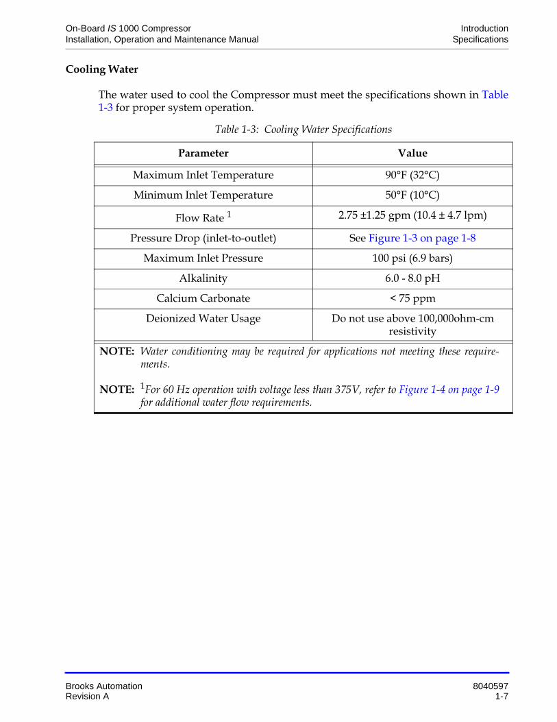
The water used to cool the Compressor must meet the specifications shown in Table 1-3 for proper system operation.
Table 1-3: Cooling Water Specifications
Parameter Value
Maximum Inlet Temperature 90°F (32°C)
Minimum Inlet Temperature 50°F (10°C)
Flow Rate 1 2.75 ±1.25 gpm (10.4 ± 4.7 lpm)
Pressure Drop (inlet-to-outlet) See Figure 1-3 on page 1-8
Maximum Inlet Pressure 100 psi (6.9 bars)
Alkalinity 6.0 - 8.0 pH
Calcium Carbonate < 75 ppm
Deionized Water Usage Do not use above 100,000ohm-cm resistivity
NOTE: Water conditioning may be required for applications not meeting these require-ments.
NOTE: 1For 60 Hz operation with voltage less than 375V, refer to Figure 1-4 on page 1-9for additional water flow requirements.

Introduction On-Board IS 1000 Compressor Specifications Installation, Operation and Maintenance Manual
8040597 Brooks Automation1-8 Revision A
Figure 1-3: Water Flow Rate Versus Pressure Drop
General
The information in Table 1-4 provides general Compressor operating specifications. See Figure 1-4 on page 1-9 for specifications of cooling water flow versus inlet temper-ature for the high voltage IS 1000 configuration.
Table 1-4: General Compressor Operating Specifications
Specification Values
Part Number 8135921G002, 8135926G002
Input Power Cable(Customer Supplied)
600 VAC10 Gauge, 3 conductor wire with groundMust conform to local electrical codes
Nominal Helium Pressure Refer to Figure 3-1 on page 3-3
Ambient Operating Tem-perature Range
50 - 100º F (10 - 38º C)
4.00
3.50
3.00
2.50
2.00
1.50
1.00
0.501 3 5 7 9 11
WA
TE
R F
LO
W R
AT
E (
GP
M)
WATER PRESSURE DROP (PSID)
ACCEPTABLE
OPERATING
LINE
.07 .49.21 .35 .63 .7715.2
13.3
11.40
9.50
7.60
5.70
3.80
1.90
WA
TE
R F
LOW
RA
TE
(LP
M)
WATER PRESSURE DROP (Bars)
NOTE: Figure 1-3 defines the water flow rate through the Compressor as a function of the pressure drop from water inlet to water outlet. You must provide the cor-rect pressure drop in your water supply system to ensure that the water flow condition meets the requirements specified in Table 1-3 on page 1-7.

On-Board IS 1000 Compressor Introduction Installation, Operation and Maintenance Manual Specifications
Brooks Automation 8040597 Revision A 1-9
NOTE: The On-Board IS 1000 Compressor is designed for continuous operation and should remain ON when the cryopumps are in a regeneration cycle.
Figure 1-4: Cooling Water Flow Versus Inlet Temperature (High Voltage Configuration)
Gas Supply ConnectorGas Return ConnectorEMO Remote Control
Receptacle
1/2 in. Aeroquip self-sealing coupling, male thread.1/2 in. Aeroquip self-sealing coupling, female thread.Mates with P5 connector part number MS3106A*
Adsorber Service Schedule 3 Years
* Supplied by Brooks Automation
Table 1-4: General Compressor Operating Specifications (Continued)
Specification Values
Introduction On-Board IS 1000 Compressor Component Description Installation, Operation and Maintenance Manual
8040597 Brooks Automation1-10 Revision A
Component Description
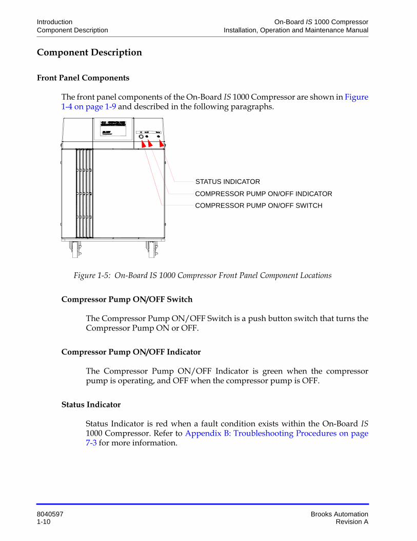
Front Panel Components
The front panel components of the On-Board IS 1000 Compressor are shown in Figure 1-4 on page 1-9 and described in the following paragraphs.
Figure 1-5: On-Board IS 1000 Compressor Front Panel Component Locations
Compressor Pump ON/OFF Switch
The Compressor Pump ON/OFF Switch is a push button switch that turns the Compressor Pump ON or OFF.
Compressor Pump ON/OFF Indicator
The Compressor Pump ON/OFF Indicator is green when the compressor pump is operating, and OFF when the compressor pump is OFF.
Status Indicator
Status Indicator is red when a fault condition exists within the On-Board IS1000 Compressor. Refer to Appendix B: Troubleshooting Procedures on page 7-3 for more information.
COMPRESSOR PUMP ON/OFF SWITCH
COMPRESSOR PUMP ON/OFF INDICATOR
STATUS INDICATOR
On-Board IS 1000 Compressor Introduction Installation, Operation and Maintenance Manual Component Description
Brooks Automation 8040597 Revision A 1-11
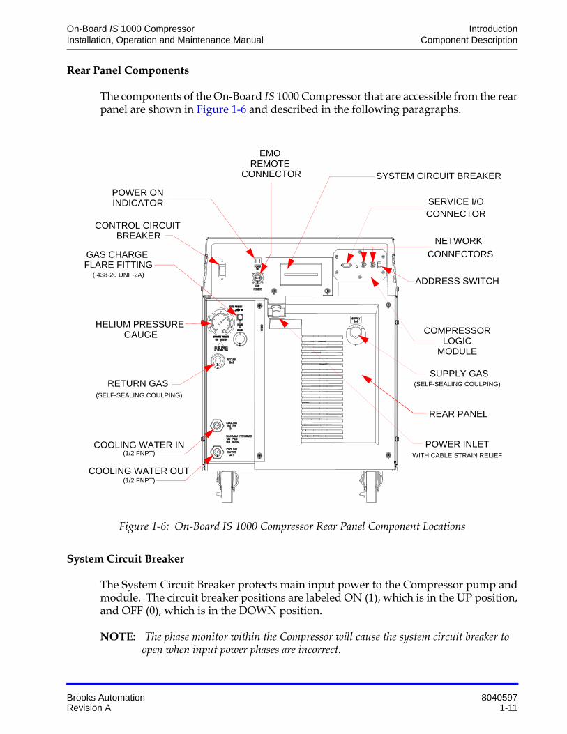
Rear Panel Components
The components of the On-Board IS 1000 Compressor that are accessible from the rear panel are shown in Figure 1-6 and described in the following paragraphs.
Figure 1-6: On-Board IS 1000 Compressor Rear Panel Component Locations
System Circuit Breaker
The System Circuit Breaker protects main input power to the Compressor pump and module. The circuit breaker positions are labeled ON (1), which is in the UP position, and OFF (0), which is in the DOWN position.
NOTE: The phase monitor within the Compressor will cause the system circuit breaker to open when input power phases are incorrect.
(1/2 FNPT)
COOLING WATER OUT(1/2 FNPT)
SUPPLY GAS
POWER INLET
EMO
POWER ON
SYSTEM CIRCUIT BREAKER
CONTROL CIRCUIT
RETURN GAS(SELF-SEALING COULPING)
HELIUM PRESSURE
GAS CHARGE
(.438-20 UNF-2A)
SERVICE I/O INDICATOR
BREAKER
GAUGE COMPRESSORLOGIC
MODULE
NETWORK
ADDRESS SWITCH
CONNECTORS
COOLING WATER IN
(SELF-SEALING COULPING)
CONNECTOR
REMOTE CONNECTOR
WITH CABLE STRAIN RELIEF
REAR PANEL
FLARE FITTING

Introduction On-Board IS 1000 Compressor Component Description Installation, Operation and Maintenance Manual
8040597 Brooks Automation1-12 Revision A
Control Circuit Breaker
The Control Circuit Breaker provides current overload protection for all internal com-ponents of the Compressor except the Compressor motor. The Compressor motor is protected by a separate overload protector. The Control Circuit Breaker opens auto-matically and must be reset manually.
Power ON Indicator
The Power On Indicator illuminates when the system and control circuit breakers are placed in the ON position and the Remote connector is closed.
Gas Charge Flared Fitting
The Gas Charge Flared Fitting is used to connect a 99.999% pure helium supply to the Compressor when helium charging is required. The fitting has SAE 45º flare.
NOTE: Refer to Maintenance on page 6-1 for information on adding helium to the Com-pressor.
Compressor Logic Module
The Compressor Logic Module monitors the status of the compressor and communi-cates with the On-Board IS Controller via channel C of the Intercomponent Network.
Helium Pressure Gauge
The Helium Pressure Gauge indicates system helium charge pressure (OFF condition) when the Compressor and cryopumps are OFF and Compressor suction or inlet pres-sure when the Compressor is ON. Refer to Table 5-1 on page 5-3 for the appropriate helium charge pressure (OFF condition).
Power Inlet
The Power Inlet is used to connect your power cable to the Compressor. Refer toInstallation on page 4-1 for information on power cable installation.
Return Gas Coupling
The Return Gas Coupling returns the helium, which has been cycled through the cryopump, back to the Compressor. Refer to Helium Refrigeration System on page 1-3 within this section for more information.

On-Board IS 1000 Compressor Introduction Installation, Operation and Maintenance Manual Component Description
Brooks Automation 8040597 Revision A 1-13
Cooling Water IN
The Cooling Water IN connector provides water to the Compressor from your facility to cool the Compressor during operation. The connector thread size is a 1/2 in. female pipe thread. The water must meet the specifications outlined in Table 1-3 on page 1-7. Refer to Installation on page 4-1 for more information on cooling water connections.
Cooling Water OUT
The Cooling Water OUT connector returns the water that has been used to cool the Compressor to your facility. The connector thread size is a 1/2 in. female pipe thread. Refer to Installation on page 4-1 for more information on cooling water connections.
EMO Remote Connector
The EMO Remote Connector is a two-pin connector. Refer to Installation on page 4-1 for more information on Compressor remote connections.
NOTE: The Compressor is shipped with a mating plug which must remain installed in the EMO Remote Connector to ensure Compressor operation when the remote EMO feature is not being used.
Supply Gas Coupling
The Supply Gas Coupling provides a connection for high pressure compressed helium to the cryopump cold head. Refer to Helium Refrigeration System on page 1-3 within this section for more information.

Introduction On-Board IS 1000 Compressor On-Board IS Cryopump Connections Installation, Operation and Maintenance Manual
8040597 Brooks Automation1-14 Revision A
On-Board IS Cryopump Connections
The On-Board IS 1000 Compressor supports the connection of multiple On-Board ISCryopumps as shown in Installation on page 4-1.
NOTE: Refer to Appendix A: Customer Brooks Automation Technical Support Informa-tion on page 7-2 and contact your local Brooks Automation Customer Support Center if you need more information on specific compressor/pump applications.

On-Board IS 1000 Compressor Safety Installation, Operation and Maintenance Manual
Brooks Automation 8040597 Revision A 2-1
2 Safety
Overview
This section describes safety conventions for the Brooks Automation Product. All personnel involved in the operation or maintenance of the product must be familiar with the safety precautions outlined in this section.
NOTE: These safety recommendations are basic guidelines. If the facility where the Prod-uct is installed has additional safety guidelines they should be followed as well, along with the applicable national and international safety codes.
Chapter Contents
Introduction . . . . . . . . . . . . . . . . . . . . . . . . . . . . . . . . . . . . . . . . . . . . . . . . . . . . . . . . . .2-2
Signal Word Descriptions . . . . . . . . . . . . . . . . . . . . . . . . . . . . . . . . . . . . . . . . . . . . . . .2-3
Safety Shape Descriptions. . . . . . . . . . . . . . . . . . . . . . . . . . . . . . . . . . . . . . . . . . . . . . .2-4
References . . . . . . . . . . . . . . . . . . . . . . . . . . . . . . . . . . . . . . . . . . . . . . . . . . . . . . . . . . . .2-4

Safety On-Board IS 1000 Compressor Introduction Installation, Operation and Maintenance Manual
8040597 Brooks Automation2-2 Revision A
Introduction
Follow all safety precautions during installation, normal operation, and when servic-ing BROOKS-Cryogenics products.
This chapter explains the safety conventions used throughout this manual. BROOKS-Cryogenics uses a specific format for cautions and warnings, which includes standard signal words and safety shapes.
See also the Customer Support appendix or call your local Customer Support Center for assistance.

On-Board IS 1000 Compressor Safety Installation, Operation and Maintenance Manual Signal Word Descriptions
Brooks Automation 8040597 Revision A 2-3
Signal Word Descriptions
All cautions and warnings contain signal words, which call attention to safety mes-sages and designate the degree of hazard seriousness. The following table shows the signal words and their meanings that may be used in this document.
Table 2-1: Safety Signal Words
Term Example Definition
CAUTION
A signal word that indicates a situa-tion or unsafe practice, which if not avoided may result in equipment damage. A CAUTION is highlighted in yellow.
CAUTION
A signal word accompanied by a safety shape that indicates a poten-tially hazardous situation or unsafe practice. If not avoided, the action may result in minor or moderate personal injury or equipment damage. A CAUTION is highlighted in yellow.
WARNING
A signal word accompanied by a safety shape that indicates indicates a potentially hazardous situation. If not avoided, the action may result in serious injury or death. A WARNING is highlighted in orange.

Safety On-Board IS 1000 Compressor Safety Shape Descriptions Installation, Operation and Maintenance Manual
8040597 Brooks Automation2-4 Revision A
Safety Shape Descriptions
All cautions and warnings contain safety shapes, which have specific safety mean-ings. The following table shows some of the safety shapes used in this document and their meanings.
References
For more information about safety standards, see the following documents:
• ISO 7010: 2003(E), Graphic symbols - Safety colours and safety signs - Safety signs used in workplaces and public areas
• ISO 3864-1: 2002(E), Graphic symbols - Safety colours and safety signs - Part 1: Design principles for safety signs in workplaces and public areas
Table 2-2: Safety Shapes
Example Term Shape Definition
General WarningIndicates a general hazard. Details about this hazard appear in the safety notice explanation.
High Voltage Indicates a high voltage hazard.
Hot Surface Indicates a surface is hot enough to cause discomfort or a burn.

On-Board IS 1000 Compressor Unpacking and Inspection Installation, Operation and Maintenance Manual
Brooks Automation 8040597 Revision A 3-1
3 Unpacking and Inspection
Overview
This chapter details the specifications of the unpacking and inspection of the Brooks Automation product.
The On-Board IS 1000 Compressor is shipped in a shipping carton incorporating a ramp system which makes removing the Compressor from the carton safe and easy.
Chapter Contents
Shipping Carton Inspection . . . . . . . . . . . . . . . . . . . . . . . . . . . . . . . . . . . . . . . . . . . . .3-2
Removal from Shipping Carton. . . . . . . . . . . . . . . . . . . . . . . . . . . . . . . . . . . . . . . . . .3-2Using the Ramp . . . . . . . . . . . . . . . . . . . . . . . . . . . . . . . . . . . . . . . . . . . . . . . . .3-2
Compressor Inspection . . . . . . . . . . . . . . . . . . . . . . . . . . . . . . . . . . . . . . . . . . . . . . . . .3-4Compressor. . . . . . . . . . . . . . . . . . . . . . . . . . . . . . . . . . . . . . . . . . . . . . . . . . . . .3-4Helium Static Pressure Verification . . . . . . . . . . . . . . . . . . . . . . . . . . . . . . . .3-4Shipping Carton Contents . . . . . . . . . . . . . . . . . . . . . . . . . . . . . . . . . . . . . . . .3-4

Unpacking and Inspection On-Board IS 1000 Compressor Shipping Carton Inspection Installation, Operation and Maintenance Manual
8040597 Brooks Automation3-2 Revision A
Shipping Carton Inspection
Inspect the exterior of the shipping carton for visible signs of damage before opening the shipping carton. Report any damage to the shipping company at once.
Removal from Shipping Carton
There are two methods of removing the On-Board IS 1000 Compressor from the ship-ping carton: using the ramp within the carton, or using a lifting device.
Using the Ramp
1. Cut the two straps on the exterior of the shipping pallet.
2. Lift the cardboard carton straight up and remove it from the pallet.
3. Cut the tape which holds the ramp in the vertical position.
4. Swing the ramp down until the end touches the floor as shown in Figure 3-1 on page 3-3.
5. Remove any excess shipping material from around the Compressor.
6. Unlock the swivel casters as shown in Figure 3-1 on page 3-3.
7. Carefully roll the Compressor down the ramp and onto the floor as shown in Figure 3-1 on page 3-3.
Personal Injury
To avoid personal injury or euipment damage, maintain control of the compressor as it rolls down the ramp.

On-Board IS 1000 Compressor Unpacking and Inspection Installation, Operation and Maintenance Manual Removal from Shipping Carton
Brooks Automation 8040597 Revision A 3-3
Figure 3-1: Using the Shipping Carton Ramp
UNLOCK SWIVEL CASTERS

Unpacking and Inspection On-Board IS 1000 Compressor Compressor Inspection Installation, Operation and Maintenance Manual
8040597 Brooks Automation3-4 Revision A
Compressor Inspection
Inspect the Compressor for visible signs of damage as indicated in the following para-graphs.
Compressor
Inspect the exterior of the Compressor for visible signs of damage, evidence of an oil leak, and check the Helium Pressure Gauge for proper helium pressure. Report any damage to the shipping company at once.
Helium Static Pressure Verification
Refer to Operation on page 5-1 for more information on the static helium charge pres-sure of the On-Board IS 1000 Compressor.
Shipping Carton Contents
The shipping carton should contain the following items:
• Compressor
• Two barbed fittings for flexible water lines
• Installation, Operation, and Maintenance manual

On-Board IS 1000 Compressor Installation Installation, Operation and Maintenance Manual
Brooks Automation 8040597 Revision A 4-1
4 Installation
Overview
This chapter provides complete installation procedures for the Brooks Automation Product including: unpacking, assembly, facilities connections, initial setup, and ini-tial check-out.
This section provides you with the information required to install the On-Board IS1000 Compressor and connect it to multiple On-Board IS Cryopump configurations.
Chapter Contents
Introduction . . . . . . . . . . . . . . . . . . . . . . . . . . . . . . . . . . . . . . . . . . . . . . . . . . . . . . . . . .4-2
Cooling Water Line Connections. . . . . . . . . . . . . . . . . . . . . . . . . . . . . . . . . . . . . . . . .4-3Hard Water Lines. . . . . . . . . . . . . . . . . . . . . . . . . . . . . . . . . . . . . . . . . . . . . . . .4-3Flexible Water Lines . . . . . . . . . . . . . . . . . . . . . . . . . . . . . . . . . . . . . . . . . . . . .4-3
Helium Flex Line Connections. . . . . . . . . . . . . . . . . . . . . . . . . . . . . . . . . . . . . . . . . . .4-5Disconnecting . . . . . . . . . . . . . . . . . . . . . . . . . . . . . . . . . . . . . . . . . . . . . . . . . . .4-6
Compressor EMO Remote Connections. . . . . . . . . . . . . . . . . . . . . . . . . . . . . . . . . . .4-7
EMO Remote Operation and EMO Box Installation. . . . . . . . . . . . . . . . . . . . . . . . .4-9
Power Cable Connections. . . . . . . . . . . . . . . . . . . . . . . . . . . . . . . . . . . . . . . . . . . . . . .4-10
Phase Check . . . . . . . . . . . . . . . . . . . . . . . . . . . . . . . . . . . . . . . . . . . . . . . . . . . . . . . . . .4-13
Compressor Logic Module Connections . . . . . . . . . . . . . . . . . . . . . . . . . . . . . . . . . .4-14
Protection from Seismic Events . . . . . . . . . . . . . . . . . . . . . . . . . . . . . . . . . . . . . . . . . .4-17Before You Start . . . . . . . . . . . . . . . . . . . . . . . . . . . . . . . . . . . . . . . . . . . . . . . . .4-17Attaching a Seismic Mount to an On-Board IS 1000 Compressor . . . . . . .4-17

Installation On-Board IS 1000 Compressor Introduction Installation, Operation and Maintenance Manual
8040597 Brooks Automation4-2 Revision A
Introduction
Figure 4-1 highlights the major tasks for Compressor installation and refers to the appropriate installation procedures within this section.
Figure 4-1: On-Board IS 1000 Compressor Installation Flowchart
Cooling WaterLine Connections
(Refer to 4-3)
Power Cable Connections
(Refer to 4-10)
Phase Check
(Refer to 4-13)
START
END
Helium Flexline Connections
(Refer to 4-5)
Compressor Logic Module Connections
(Refer to 4-14)
EMO Remote Operations*
(Refer to 4-9)
* ONLY REQUIRED FOR REMOTE EMO COMPRESSOR

On-Board IS 1000 Compressor Installation Installation, Operation and Maintenance Manual Cooling Water Line Connections
Brooks Automation 8040597 Revision A 4-3
Cooling Water Line Connections
NOTE: The water used for cooling the Compressor must meet the specifications outlined in Table 1-1 on page 1-6.
Hard Water Lines
1. Apply a light coating of standard plumbing thread sealant to the hard line pipe threads.
2. Install the Supply hard line into the INPUT connection on the rear panel of the Compressor. Tighten the fitting by hand.
3. Install the Return hard line into the OUTPUT connection on the rear panel of the Compressor. Tighten the fitting by hand.
4. Using a wrench, tighten the fittings.
5. Allow water to flow and check for leaks at the rear of the Compressor.
Flexible Water Lines
1. Apply a light coating of standard plumbing thread sealant to the barbed fitting threads.
2. Install the barbed fittings into the INPUT and OUTPUT connections on the rear panel of the Compressor.
3. Using a wrench, tighten the barbed fittings.
Connector Thread Damage
To avoid damaging the input and output connector threads, do not overtighten the ferrules.
Connector Thread Damage
To avoid damaging the input and output connector threads, do not overtighten the barbed fittings.

Installation On-Board IS 1000 Compressor Cooling Water Line Connections Installation, Operation and Maintenance Manual
8040597 Brooks Automation4-4 Revision A
4. Connect the Supply flexible water line to the INPUT barbed fitting and secure with a hose clamp.
5. Connect the Return flexible water line to the OUTPUT barbed fitting and secure with a hose clamp.
6. Allow water to flow and check for leaks at the rear of the Compressor.

On-Board IS 1000 Compressor Installation Installation, Operation and Maintenance Manual Helium Flex Line Connections
Brooks Automation 8040597 Revision A 4-5
Helium Flex Line Connections
The use of several On-Board IS 1000 Compressors on a single manifold feeding a com-mon supply header and a common return header requires special precautions. Con-tact Brooks Automation for a review of the intended installation and for specific technical instructions.
The number of On-Board IS Cryopumps connected to an On-Board IS 1000 Compres-sor will vary based upon the On-Board IS Cryopump models used. Refer to Appendix A: Customer Brooks Automation Technical Support Information on page 7-2 for information about specific compressor/pump applications.
Connecting
1. Remove all dust plugs and caps from the Gas Supply and Return lines, and the Compressor and cryopump Supply and Return connectors. Check for the pres-ence of a flat gasket in the male connector, and no gasket in the female connec-tor.
2. Connect the Gas Return line to the GAS RETURN connector on the rear of the Compressor and then to the GAS RETURN connector on the On-Board ISCryopump or helium manifold. Using two wrenches as shown in Figure 4-2 on page 4-6, tighten the connector.
Equipment Damage
To avoid damaging equipment from excessive or insufficient pressure, do not connect the On-Board IS Cryopump to a manifold with other compressors, On-Board, or Cryo-Torr cryopumps.
Equipment Damage
To avoid damaging the connector, O-ring seals, or causing a helium circuit leak, connect and disconnect the helium flex lines from the On-Board IS 1000 Compressor using the following procedure and as shown in Figure 4-2 on page 4-6.

Installation On-Board IS 1000 Compressor Helium Flex Line Connections Installation, Operation and Maintenance Manual
8040597 Brooks Automation4-6 Revision A
Figure 4-2: Connecting/Disconnecting Helium Flex Line Self Sealing Couplings
3. Connect the Gas Supply line to the GAS SUPPLY connector on the rear of the Compressor and then to the GAS SUPPLY connector on the On-Board ISCryopump or helium manifold. Using two wrenches as shown in Figure 4-2, tighten the connector.
4. Attach the Supply and Return line identification labels to each end of the appropriate lines.
Disconnecting
• Using two wrenches as shown in Figure 4-2, disconnect the two self sealing coupling connectors quickly to minimize helium leakage.
TO TIGHTEN
TO LOOSEN
TURN WITH 1 3/16 INCH WRENCH
HOLD WITH 1 INCH WRENCH
HOLD WITH 1 1/8 INCH WRENCH
TURN WITH 1 3/16 INCH WRENCH

On-Board IS 1000 Compressor Installation Installation, Operation and Maintenance Manual Compressor EMO Remote Connections
Brooks Automation 8040597 Revision A 4-7
Compressor EMO Remote Connections
NOTE: Connections to the EMO Remote Connector are only required if the Compressor uses the remote EMO box.
NOTE: The Compressor is shipped with a mating plug which must remain installed in the EMO Remote Connector to ensure Compressor operation when the EMO remote feature is not being used.
1. Remove the EMO Remote plug from the EMO REMOTE connector on the Compressor rear panel.
2. Disassemble the plug connector.
3. Unsolder the jumper wire between the pins.
4. Slide the connector components over the cable as shown in Figure 4-3.
Figure 4-3: EMO Remote Connections
5. Strip the insulation from the customer supplied cable conductors and tin the conductors with solder.
6. Solder the conductors of the customer supplied cable to the plug pins as shown in Figure 4-3.
7. Align the key in the connector shell with the pin assembly and install the pin assembly into the shell.
8. Install the lock washer around the pin assembly.
9. Slide the locking ring over the shell.
SHELL
PIN ASSEMBLY
LOCK WASHERLOCKING RING
BODY
REMOTE EMOCONNECTOR
STRAIN RELIEF

Installation On-Board IS 1000 Compressor Compressor EMO Remote Connections Installation, Operation and Maintenance Manual
8040597 Brooks Automation4-8 Revision A
10. Screw the connector body into the shell threads.
11. Connect the plug to the REMOTE EMO CONNECTOR on the Compressor.
12. Connect the opposite end to the EMO box.
13. Assemble and screw the strain relief on the body and tighten the cable clamp screws.

On-Board IS 1000 Compressor Installation Installation, Operation and Maintenance Manual EMO Remote Operation and EMO Box Installation
Brooks Automation 8040597 Revision A 4-9
EMO Remote Operation and EMO Box Installation
Installing the EMO box is optional. The remote EMO is mounted on the compressor with the kit provided. If the EMO box is not used, the jumper connector must be installed.
To initiate the EMO function, push the red button in. The EMO circuit immediately locks out the compressor to keep it from running. To reset power to the unit, make sure the main circuit breaker (CB1) is in the off position. Turn the EMO button clock-wise and pull it out. Turn the unit back on with the circuit breakers and front power switch.
To reset the EMO, remove power by initiating these procedures:
1. Push the start button off and on.
2. Turn the control circuit breaker off then back on.
3. Turn the main circuit breaker off and on.

Installation On-Board IS 1000 Compressor Power Cable Connections Installation, Operation and Maintenance Manual
8040597 Brooks Automation4-10 Revision A
Power Cable Connections
The following procedure provides information for making all three phase (342-528 VAC for high voltage and 180 - 250 VAC for low voltage) electrical connections to the Compressor.
NOTE: Input phasing sequence = counter-clockwise. Make sure that the lockout procedure (as defined by the facility) has been followed before initiating the following proce-dure.
1. Cut a 10 AWG (6.00 mm2), 3 conductor cable with ground to an appropriate length.
2. Strip the cable jacket back 4 in. (101.6 mm).
3. Strip the insulation back 3/8 in. (9.3 mm) on each individual conductor.
4. Install a #10 ring tongue terminal on the end of each conductor using the appropriate size double crimping tool.
High Voltage
To avoid severe injury or loss of life from high voltage electric shock, turn off all electrical power before proceeding.
Equipment Failure
To avoid equipment failure, use a 10 gauge, 3 conductor cable with ground rating at 600 VAC for the Compressor

On-Board IS 1000 Compressor Installation Installation, Operation and Maintenance Manual Power Cable Connections
Brooks Automation 8040597 Revision A 4-11
Figure 4-4: On-Board IS 1000 Compressor Connection Covers
5. Remove the rear panel and the circuit breaker terminal cover in Figure 4-4.
6. Thread the conductor cable through the cable strain relief in Figure 4-4.
Figure 4-5: Circuit Breaker Area
7. Remove the 10-32 nut from the ground stud and install the grounding wire.
8. Replace the 10-32 nut on the ground stud and tighten to 18 in.-lbs (0.21m-kg).
REAR PANEL
CIRCUIT BREAKER TERMINAL COVERCABLE STRAIN RELIEF
SEE FIGURE 3-5FOR CIRCUIT BREAKERDETAILS
MODULE
GROUND STUD WITHCIRCUIT BREAKER10-32 NUTTERMINALS

Installation On-Board IS 1000 Compressor Power Cable Connections Installation, Operation and Maintenance Manual
8040597 Brooks Automation4-12 Revision A
NOTE: Use a slotted screwdriver that is capable of holding a screw when performing Step 9 and Step 11.
9. Remove the terminal screws from the circuit breaker terminals X, Y, and Z in Figure 4-5 on page 4-11.
NOTE: The phase order in which the conductor terminal lugs are connected to circuit breaker terminals X, Y, and Z are determined during the Phase Check Procedure.
NOTE: For installation where one of the three phase legs is at or near ground potential, connect that leg to terminal Y on the Compressor.
10. Install the conductor terminal lugs to the circuit breaker terminals X, Y, and Z.
11. Replace and tighten the terminal screws to 12 in.-lbs (0.14m-kg).
12. Allow enough cable to stay in the circuit breaker area to prevent strain on the termianl connections, and then tighten the screws on the cable strain relief in Figure 4-4 on page 4-11.
13. Install the power source end of the conductor cable according to the local elec-trical codes.
14. Replace the circuit breaker terminal cover from Figure 4-4 on page 4-11.
Proceed with Phase Check on page 4-13.

On-Board IS 1000 Compressor Installation Installation, Operation and Maintenance Manual Phase Check
Brooks Automation 8040597 Revision A 4-13
Phase Check
1. Apply 208 VAC (for low voltage) or 380/480 VAC (for high voltage) power to the On-Board IS 1000 Compressor circuit.
NOTE: The System Circuit Breaker will trip immediately during step 2 if the power phase connections are not correct.
2. Set the System Circuit Breaker (CB1) to the ON position.
3. If the System Circuit Breaker trips, refer to step Step 4. If the System Circuit Breaker does not trip, refer to step Step 5.
4. If the System Circuit Breaker trips, perform the following steps:
1. Set the System Circuit Breaker (CB1) to the OFF position.
2. Disconnect the power cord from the power source.
3. Remove the circuit breaker terminal cover.
4. Reverse the wiring order of terminals X and Y.
5. Torque the circuit breaker terminal screws to 12 in.-lbs.
6. Install the circuit breaker terminal cover.
7. Repeat Step 1 through Step 3 of this procedure.
5. Make sure the Power On indicator is illuminated.
6. Set the System Circuit Breaker (CB1) to the OFF position.
7. Install the rear panel.
High Voltage
To avoid severe injury or loss of life from high voltage electric shock, ensure that all steps in the previous section, Power Cable Connections on page 4-10, and the current section are followed precisely.

Installation On-Board IS 1000 Compressor Compressor Logic Module Connections Installation, Operation and Maintenance Manual
8040597 Brooks Automation4-14 Revision A
Compressor Logic Module Connections
1. Refer to the On-Board IS Controller Quick Installation Guide (8040648 or 8040657) for information on connecting the On-Board IS 1000 Compressor to the Intercomponent Network.
High Voltage
To avoid severe injury or loss of life from high voltage electric shock, turn off the compressor power before making any connections to the rear panel.

On-Board IS 1000 Compressor Installation Installation, Operation and Maintenance Manual Compressor Logic Module Connections
Brooks Automation 8040597 Revision A 4-15
Figure 4-6: Single On-Board IS 1000 Compressor - Multiple On-Board IS Cryopump Configuration
HE
LIUM
SU
PP
LY
HE
LIUM
RE
TU
RN
ON-BOARD IS 1000 COMPRESSOR
208 VAC50/60 HZ
208 VAC50/60 HZ
208 VAC50/60 HZ
208 VAC50/60 HZ
208 VAC50/60 HZ
208 VAC, 50/60 HZ (low voltage) or380/480 VAC, 50/60 HZ (high voltage)
COOLING WATER IN
COOLING WATER OUT

Installation On-Board IS 1000 Compressor Compressor Logic Module Connections Installation, Operation and Maintenance Manual
8040597 Brooks Automation4-16 Revision A
Figure 4-7: Multiple On-Board IS 1000 Compressor - Multiple On-Board IS Cryopump Configuration
HE
LIUM
SU
PP
LY
HE
LIUM
RE
TU
RN
On-Board IS 1000 COMPRESSORS
208 VAC50/60 HZ
208 VAC50/60 HZ
208 VAC50/60 HZ
208 VAC50/60 HZ
208 VAC50/60 HZ
208 VAC50/60 HZ
FL
OW
FL
OW
FL
OW
208 VAC50/60 HZ
208 VAC50/60 HZ
FL
OW
208 VAC, 50/60 HZ (low voltage) or
380/480 VAC, 50/60 HZ (high voltage)
208 VAC, 50/60 HZ (low voltage) or
380/480 VAC, 50/60 HZ (high voltage)

On-Board IS 1000 Compressor Installation Installation, Operation and Maintenance Manual Protection from Seismic Events
Brooks Automation 8040597 Revision A 4-17
Protection from Seismic Events
The On-Board IS 1000 Compressor unit is designed to be secured from movement and overturning in the case of a seismic event. This is to prevent risk of injury to personnel and equipment damage in compliance with semi-S2, section 19.
Brooks Automation offers an optional seismic mount kit (8187012K001) to secure the compressor. The mount can be installed using the On-Board IS 1000 Compressor Seismic Mount Kit Quick Installation Guide (8040704).
If you choose to mount your own device, please use the following guidelines.
Before You Start
Before installing a seismic mount:
1. Disconnect the On-Board IS 1000 Compressor from all electrical, gas and water connections.
2. Disconnect any On-Board IS 1000 Compressor pump connections.
3. Use a lifting device that can safely lift and hold the On-Board IS 1000 Compres-sor as indicated in Step 1 of the Attaching a Seismic Mount to an On-Board IS1000 Compressor procedure below.
Attaching a Seismic Mount to an On-Board IS 1000 Compressor
To attach a seismic mount to the compressor:
1. Use a lifting device that can safely lift and hold the On-Board IS 1000 Compres-sor (222 lbs [102 kg]) so that you can safely access the bottom.
2. Place mounting blocks for added safety to ensure that the compressor is secure and stationary.
3. Use a 7/16” wrench or socket to remove the eight 1/4-20 x 0.75 hex bolts (PN MS35307-305) and 1/4” lock washer (PN 7001015P008) that secure each of the four casters at the bottom of the compressor. See Figure 4-8 on page 4-18 for bolt and caster locations.

Installation On-Board IS 1000 Compressor Protection from Seismic Events Installation, Operation and Maintenance Manual
8040597 Brooks Automation4-18 Revision A
Figure 4-8: Removing the Caster Hex Bolts from the Compressor Bottom
4. If you raised the unit using a lifting device, remove the mounting blocks and carefully, slowly and safely lower the IS 1000 Compressor to the mounting locations.
REMOVE CASTER HEX BOLTS

On-Board IS 1000 Compressor Installation Installation, Operation and Maintenance Manual Protection from Seismic Events
Brooks Automation 8040597 Revision A 4-19
Figure 4-9: Seismic Mount Mounting Points
5. Attach the seismic mounts to the four 1/4-20 mounting points shown in Figure 4-9.
ATTACH SEISMIC MOUNTS AT POINTS INDICATED

Installation On-Board IS 1000 Compressor Protection from Seismic Events Installation, Operation and Maintenance Manual
8040597 Brooks Automation4-20 Revision A
This Page Intentionally Left Blank

On-Board IS 1000 Compressor Operation Installation, Operation and Maintenance Manual
Brooks Automation 8040597 Revision A 5-1
5 Operation
Overview
This chapter provides operation instructions for the Brooks Automation Product.
Chapter Contents
Adjusting System Helium Pressure . . . . . . . . . . . . . . . . . . . . . . . . . . . . . . . . . . . . . .5-2
OFF Condition Helium System Pressure Verification . . . . . . . . . . . . . . . . . . . . . . .5-3
Compressor Operation . . . . . . . . . . . . . . . . . . . . . . . . . . . . . . . . . . . . . . . . . . . . . . . . .5-4
Replacement of Helium Circuit Components . . . . . . . . . . . . . . . . . . . . . . . . . . . . . .5-6

Operation On-Board IS 1000 Compressor Adjusting System Helium Pressure Installation, Operation and Maintenance Manual
8040597 Brooks Automation5-2 Revision A
Adjusting System Helium Pressure
Your high vacuum pump system is comprised of several pressurized components i.e. compressor, flex lines, and cryopumps. Each component is charged with helium before shipment. After all cryopumps, helium lines, and manifolds are attached to the compressor, the system helium charge pressure (OFF condition) must be verified beforesystem operation. Once the helium system pressure (OFF condition) has been veri-fied, the system is ready for operation. After cooldown, the normal system operating pressure is recorded.
NOTE: The On-Board IS 1000 Compressor is designed for continuous operation and should remain ON even when the cryopumps are in a regeneration cycle.

On-Board IS 1000 Compressor Operation Installation, Operation and Maintenance Manual OFF Condition Helium System Pressure Verification
Brooks Automation 8040597 Revision A 5-3
OFF Condition Helium System Pressure Verification
The proper system helium charge pressure (OFF condition) is necessary so that the cryopumps operate at maximum performance as well as to assure that the compressor will operate below the maximum design motor winding temperature which will max-imize the life of the compressor motor.
1. Make sure the Compressor and Cryopump(s) are OFF.
2. Make sure all system components are connected together as described in Installation on page 4-1.
3. Allow all system components to acclimate to a temperature between 60º F and 80º F (15.5º C - 26.6º C).
4. Read the compressor helium pressure gauge located on the compressor rear panel as shown in Figure 1-1 on page 1-4. Compare the gauge reading to the appropriate 50/60 Hz line frequency value (depending upon your system installation) indicated in Table 5-1.
NOTE: The use of a higher helium charge pressure for 50 HZ operation is necessary in order to compensate for the slower speed at which the compressor operates at 50 HZ. The charge level (OFF condition) for 60 Hz remains at 340 - 350 PSIG.
5. If the helium charge pressure (OFF condition) is not within the ranges as indi-cated in Table 5-1, then adjust the charge pressure as described in Maintenanceon page 6-1.
Table 5-1: On-Board IS 1000 Compressor Helium Charge (OFF Condition)
Line Frequency Helium Charge Pressure (OFF Condition)
60 Hz 340 - 350 psig (23.4 - 24.1 bar)
50 Hz 355 - 365 psig (24.5 - 25.2 bar)
Relief Valve Damage
To avoid damaging relief valves, do not exceed the recommended system helium charge pressure (OFF condition).

Operation On-Board IS 1000 Compressor Compressor Operation Installation, Operation and Maintenance Manual
8040597 Brooks Automation5-4 Revision A
Compressor Operation
NOTE: If the gauge indicator is below 140 psig, then check the system for insufficient helium or helium leaks. If the gauge indicator is above 240 psig, then the system has been over pressurized. Refer to Maintenance on page 6-1 and either add or remove helium before operating the On-Board IS 1000 Compressor.
The system may be operated once the helium charge pressure is correct. Perform the following steps to start the compressor:
1. Close all On-Board IS Cryopump gate valves.
2. Set the On-Board IS 1000 Compressor System Circuit Breaker to the ON (UP) position.
3. Set the On-Board IS 1000 Compressor Control Circuit Breaker to the ON (UP) position.
4. Set the power switch on the front panel of the On-Board IS 1000 Compressors to the ON position.
5. Refer to Section 1 of the On-Board IS Cryopump System Operation Guide, part number 8040647 (that came with your On-Board IS Controller) for additional system startup information.
6. Once the second stage temperature for all cryopumps is below 17K, record the compressor pressure gauge reading as the normal system operating pressure.
NOTE: During compressor operation, the compressor gauge reads the pressure of the gas entering the compressor prior to it being compressed.
7. Affix a copy of the data next to the compressor gauge on each compressor. This data is to be verified for each tool installation and whenever a configuration change is made affecting the amount of system helium gas and line volume.
The compressor pressure reading will decrease from the normal system oper-ating pressure during cryopump regeneration or if fewer cryopumps are being
Equipment Damage
To avoid damaging equipment from excessive or insufficient pressure, maintain between 140 psig and 240 psig.
On-Board IS 1000 Compressor Operation Installation, Operation and Maintenance Manual Compressor Operation
Brooks Automation 8040597 Revision A 5-5
operated. These are normal variations in the compressor pressure reading and should not be cause for concern.
NOTE: If you have concerns about system performance changing, then check the normal system operating pressure which was determined in Compressor Operation on page 5-4. If the normal system operating pressure is not correct, check the system for leaks.
Once the leaks have been repaired, helium must be added to return the system to nor-mal operating system pressure as described in Maintenance on page 6-1.

Operation On-Board IS 1000 Compressor Replacement of Helium Circuit Components Installation, Operation and Maintenance Manual
8040597 Brooks Automation5-6 Revision A
Replacement of Helium Circuit Components
On occasion, it may be necessary to replace components such as cryopumps, helium gas lines or compressors, or change the configuration of the system. Whenever any of these conditions occur, OFF Condition Helium System Pressure Verification on page 5-3 should be performed to ensure that (OFF condition) helium pressure has not changed.
The use of several On-Board IS 1000 Compressors on a single manifold feeding a com-mon supply header and a common return header requires special precautions. Con-tact Brooks Automation for a review of the intended installation and for specific technical instructions.
Relief Valve Damage
To avoid damaging relief valves when using other compressor models, reduce the system helium charge pressure to 200 - 210 psig.

On-Board IS 1000 Compressor Maintenance Installation, Operation and Maintenance Manual
Brooks Automation 8040597 Revision A 6-1
6 Maintenance
Overview
This chapter provides maintenance directions for the Brooks Automation Product.
Chapter Contents
Scheduled Maintenance . . . . . . . . . . . . . . . . . . . . . . . . . . . . . . . . . . . . . . . . . . . . . . . .6-2Suggested Maintenance Equipment . . . . . . . . . . . . . . . . . . . . . . . . . . . . . . . .6-2Adsorber Replacement . . . . . . . . . . . . . . . . . . . . . . . . . . . . . . . . . . . . . . . . . . .6-2
Adjusting System Helium Pressure . . . . . . . . . . . . . . . . . . . . . . . . . . . . . . . . . . . . . .6-5Reducing Helium Pressure. . . . . . . . . . . . . . . . . . . . . . . . . . . . . . . . . . . . . . . .6-5Increasing Helium Pressure . . . . . . . . . . . . . . . . . . . . . . . . . . . . . . . . . . . . . . .6-6Adding Helium . . . . . . . . . . . . . . . . . . . . . . . . . . . . . . . . . . . . . . . . . . . . . . . . .6-6

Maintenance On-Board IS 1000 Compressor Scheduled Maintenance Installation, Operation and Maintenance Manual
8040597 Brooks Automation6-2 Revision A
Scheduled Maintenance
Suggested Maintenance Equipment
It is recommended to have the following equipment and disposable supplies avail-able as listed in Table 6-1.
Adsorber Replacement
Use the following procedure to replace the adsorber every three years.
1. Set the System Circuit Breaker, on the rear of the On-Board IS 1000 Compres-sor, to the OFF position.
2. Remove the four screws which secure the rear panel to the Compressor and remove the rear panel.
NOTE: Use two wrenches in Step 3 to prevent loosening the body of the coupling.
3. Using a 1-3/16 in. wrench, and a 1-1/8 in. wrench, as shown in Figure 6-1 on page 6-3, disconnect the two self sealing coupling connectors quickly to mini-mize helium leakage.
Table 6-1: Suggested Maintenance Equipment
Supply Part Number
Helium, 99.999% pure -
Pressure regulator (0-3000/0-400 psi) Assy.
8031403
Helium charging line terminating in a 1/4-inchfemale flare fitting
7021002P001
Lint-free gloves and cloth -
Oakite or equivalent detergent soap -
Denatured alcohol -
NOTE: NOTE: Refer to Appendix A: Customer Brooks Automation Technical Support Information on page 7-2 and contact your local Brooks Automa-tion Support Center to obtain the parts listed in this table.
NOTE: NOTE: MSDS sheet for oil used in the compressor is available upon request.

On-Board IS 1000 Compressor Maintenance Installation, Operation and Maintenance Manual Scheduled Maintenance
Brooks Automation 8040597 Revision A 6-3
Figure 6-1: Disconnecting Self Sealing Couplings
4. Using a 7/16 in. (11mm) wrench, remove the adsorber mounting bolt as shown in Figure 6-2 on page 6-4.
5. Move the adsorber from under the mounting tabs in the base as shown in Fig-ure 6-2 on page 6-4 and remove the adsorber from the Compressor.
6. Install the replacement adsorber under the mounting tabs and secure it into place with the bolt removed in Step 4.
7. Using two wrenches as shown in Figure 6-1, connect the two self sealing cou-plings quickly to minimize helium leakage.
8. Install the Compressor rear panel.
9. Ensure that the pressure gauge reads the proper value as shown in Table 5-1 on page 5-3. If additional gas pressure is required, refer to Adding Helium within this section. If gas pressure needs to be reduced, refer to Reducing Helium Pressure within this section.
10. Record the adsorber replacement date on the adsorber label and also note that the next adsorber replacement should be performed in three years.
NOTE: Follow local, state and federal guidelines when disposing of the adsorber.
TO TIGHTEN
TO LOOSEN
TURN WITH 1 3/16 INCH WRENCH
HOLD WITH 1 INCH WRENCH
HOLD WITH 1 1/8 INCH WRENCH
TURN WITH 1 3/16 INCH WRENCH

Maintenance On-Board IS 1000 Compressor Scheduled Maintenance Installation, Operation and Maintenance Manual
8040597 Brooks Automation6-4 Revision A
Figure 6-2: Adsorber Location within the On-Board IS 1000 Compressor (Rear Panel Removed)
Adsorber Mounting Bolt
ADSORBER

On-Board IS 1000 Compressor Maintenance Installation, Operation and Maintenance Manual Adjusting System Helium Pressure
Brooks Automation 8040597 Revision A 6-5
Adjusting System Helium Pressure
NOTE: These procedures can be performed on a compressor that is turned ON or OFF. However, the helium pressure gauge should be set to the helium charge pressure (OFF condition) value if the compressor is turned OFF or set to the normal system operating pressure if the compressor is turned ON. Refer to Operation on page 5-1 for more information.
Reducing Helium Pressure
NOTE: You must obtain the normal system operating pressure from Table 5-1 on page 5-3 in order to perform this procedure. If the normal system operating pressure is unknown, then shut the compressor OFF and perform the OFF Condition Helium System Pressure Verification on page 5-3 procedure instead.
1. Remove the flare cap from the gas charge flared fitting as shown in Figure 6-3.
Figure 6-3: Helium Pressure Control Components
2. Open the gas charge control valve very slowly to allow a slight amount of helium to escape. Leave the valve open until the helium pressure gauge indi-cates one of the following:
• To the appropriate value in Table 5-1 on page 5-3 if the compressor is OFF and acclimated to a temperature between 60º F and 80º F (15.5º C - 26.6º C).
• To the value previously recorded in the Compressor Operation on page 5-4 procedure if the compressor is ON.
3. Close the gas charge control valve and replace the flare cap.
GAS CHARGE FLARED FITTING
HELIUM PRESSURE GUAGE
GAS CHARGE CONTROL VALVE
REAR PANEL

Maintenance On-Board IS 1000 Compressor Adjusting System Helium Pressure Installation, Operation and Maintenance Manual
8040597 Brooks Automation6-6 Revision A
Increasing Helium Pressure
Use the following procedure to increase the helium pressure if the indicated pressure is below the appropriate value as shown in Table 5-1 on page 5-3.
Adding Helium
NOTE: You must obtain the normal system operating pressure from Table 5-1 on page 5-3 in order to perform this procedure. If the normal system operating pressure is unknown, then shut the compressor OFF and perform the OFF Condition Helium System Pressure Verification on page 5-3 procedure instead.
This procedure ensures that both the regulator and the charging line will be purged of air and that the air trapped in the regulator will not diffuse back into the helium bot-tle. For best results, use a dedicated helium bottle, regulator, and line, which are never separated, for adding helium.
NOTE: You are required to supply the helium charging line terminating in a 1/4-inch female flare fitting, and a two-stage pressure regulator rated at 0-3000/0-400 psig for this operation.
1. Attach a regulator (0-3000/0-400 psig) and charging line to a helium bottle (99.999% pure).
NOTE: Do not open the bottle at this time.
Equipment Damage
To avoid damaging equipment due to insufficient helium, check for leaks if helium must be added to the system more than once every few months. A helium leak may be caused by improperly connected self-sealing connections or any mechanical joint within the compressor
Equipment Failure
Use only 99.999% pure helium gas. Helium circuit contamination may result if a lower quality of helium is used.

On-Board IS 1000 Compressor Maintenance Installation, Operation and Maintenance Manual Adjusting System Helium Pressure
Brooks Automation 8040597 Revision A 6-7
2. Purge the regulator and charging lines as follows:
1. Open the regulator a small amount by turning the adjusting knob clock-wise until it contacts the diaphragm, then turn approximately 1/8 to 1/4 turn more, so that the regulator is barely open.
2. Loosely connect the charge line to the helium pressure regulator.
3. Slowly open the bottle valve, and purge the regulator and line for 10 to 15 seconds. Turn the regulator knob counterclockwise until the helium stops flowing.
3. Remove the flare cap of the gas charge flared fitting on the rear of the Compres-sor.
4. Loosely connect the charging line from the helium pressure regulator to the 1/4-inch male flare fitting installed on the helium charge valve. Purge the charge line again, as in step a, for 30 seconds, and tighten the charge line flare fitting onto the gas charge fitting while the helium is flowing.
5. Set the helium pressure regulator to 300 psig (20.7 bars). If the compressor is ON, proceed with step a. If the compressor is OFF, proceed with Step 2.
1. Obtain the previously recorded normal system operating pressure oper-ating pressure from Table 5-1 on page 5-3. Open the gas charge control valve very slowly and allow helium to flow until the compressor gauge reading is the same as the value obtained from Section 4. Quickly close the gas charge control valve.Table 5-1 on page 5-3
2. Obtain the appropriate (50 or 60 Hz) system operating pressure (OFF con-dition) from Table 5-1 on page 5-3. Open the gas charge control valve very slowly and allow helium to flow until the compressor gauge reading is the same as the appropriate value in Table 5-1 on page 5-3. Quickly close the gas charge control valve.
6. Ensure that the helium charge valve on the Compressor is tightly closed. Shut off the helium pressure regulator on the helium bottle and remove the charging line from the male flare fitting. Reinstall the flare cap.

Maintenance On-Board IS 1000 Compressor Adjusting System Helium Pressure Installation, Operation and Maintenance Manual
8040597 Brooks Automation6-8 Revision A
This Page Intentionally Left Blank

On-Board IS 1000 Compressor Appendices Installation, Operation and Maintenance Manual
Brooks Automation 8040597 Revision A 7-1
7 Appendices
Overview
The following appendices are included to provide the user with a single location for specific information related to the Brooks Automation Product.
Chapter Contents
Appendix A: Customer Brooks Automation Technical Support Information . . .7-2
Appendix B: Troubleshooting Procedures . . . . . . . . . . . . . . . . . . . . . . . . . . . . . . . . .7-3Troubleshooting the Compressor . . . . . . . . . . . . . . . . . . . . . . . . . . . . . . . . . .7-3Technical Inquiries. . . . . . . . . . . . . . . . . . . . . . . . . . . . . . . . . . . . . . . . . . . . . . .7-3Front Panel Indicators . . . . . . . . . . . . . . . . . . . . . . . . . . . . . . . . . . . . . . . . . . . .7-3
Appendix C: Diagrams . . . . . . . . . . . . . . . . . . . . . . . . . . . . . . . . . . . . . . . . . . . . . . . . .7-9

Appendices On-Board IS 1000 Compressor Appendix A: Customer Brooks Automation Technical Support Information Installation, Operation and Mainte-
8040597 Brooks Automation7-2 Revision A
Appendix A: Customer Brooks Automation Technical Support Information
When contacting Brooks Automation for Technical Support, please have the follow-ing information available.
1. Record the part number and serial number from the equipment.
2. Provide the installed location of the equipment.
3. Provide name, e-mail address, and telephone number of the person to contact.
4. List any error codes received during the failure.
5. Prepare a detailed description of the events relating to the error.
• Time that the equipment has been in operation
• Work that was done on the equipment prior to the error
• Functions that the equipment was performing when the error occurred
• Actions taken after the error and the results of those actions
• Other information that may assist the Specialist
6. Contact Brooks Automation Technical Support at these numbers:
For additional contact information, please go to the Brooks Automation web site at www.brooks.com or send an E-mail to [email protected].
Brooks Location GUTS® Contact Number
North America
1-800-FOR-GUTS (1-800-367-4887) US/Canada+1-978-262-2900
Europe +49 1804 CALL GUTS (+49 1804 2255 4887)Japan +81-45-477-5980China +86-21-5131-7066Taiwan +886-3-552-5225Korea +82-31-288-2500Singapore +65-6464-1481

On-Board IS 1000 Compressor Appendices Installation, Operation and Maintenance Manual Appendix B: Troubleshooting Procedures
Brooks Automation 8040597 Revision A 7-3
Appendix B: Troubleshooting Procedures
Troubleshooting the Compressor
The Compressor troubleshooting procedures are summarized in Table 7-1 on page 7-4.
NOTE: Disconnect the compressor before performing any troubleshooting procedures.
Technical Inquiries
NOTE: Refer to Appendix A: Customer Brooks Automation Technical Support Informa-tion on page 7-2 for customer support information and contact Brooks Automation for assistance if required.
Front Panel Indicators
The On-Board IS 1000 Compressor front panel contains two indicators; a green power indicator and a red status indicator as shown in Figure 7-1 on page 7-4. When the red status indicator is illuminated, a fault condition exists. Refer to Table 7-1 on page 7-4to locate the problem.
Hot Surface
To avoid burns, wait for the pump to cool down before working on the inside of the compressor.
Compressor Damage
To avoid damaging the compressor, do not change or modify any compressor internal wiring circuits.

Appendices On-Board IS 1000 Compressor Appendix B: Troubleshooting Procedures Installation, Operation and Maintenance Manual
8040597 Brooks Automation7-4 Revision A
Figure 7-1: On-Board IS 1000 Compressor Front Panel Indicators
Table 7-1: Compressor Troubleshooting Procedures
Problem Possible Cause Corrective Action
1. System circuit breaker (CB1) trips immediately to the OFF (0) position when switched to the ON (1) position.Power Indicator OFFStatus Indicator OFF
1a. Incorrect phasing of input power.
1a. Check phasing of input power. Refer to Phase Check on page 4-13.
GREEN POWER ON INDICATOR
RED STATUS INDICATOR
I/O On/Off Status

On-Board IS 1000 Compressor Appendices Installation, Operation and Maintenance Manual Appendix B: Troubleshooting Procedures
Brooks Automation 8040597 Revision A 7-5
2. System (CB1) and Con-trol Circuit (CB2) circuit breakers remain in the ON (1) position when switched ON but the compressor will not run.Power Indicator OFFStatus Indicator OFF
2a. No power coming from source.
2a. Check source fuses, circuit breakers, and wir-ing associated with the power source. Repair as needed.
2b. Insufficient power. 2b. Verify adequate phase-to-phase input voltage. Refer to Table 1-1 on page 1-6.
2c. EMO remote jumper plug is not properly installed.
2c. Check that the EMO remote jumper plug is fully seated. See Figure 6-1 on page 6-3 for location. Refer to EMO Remote Operation and EMO Box Installation on page 4-9 for more information. Reset the CB1 circuit breaker.
2d. Improperly wired external EMO remote con-trol circuit. NOTE: Only applies if EMO remote con-trol feature is being used.
2d. Verify correct installa-tion of EMO remote con-trol feature.
3. System circuit breaker (CB1) will not remain in the ON (1) position when switched ON. The Con-trol Circuit circuit breaker (CB2) trips when excessive current is being drawn by 24 volt com-pressor control circuits.Power Indicator OFFStatus Indicator OFF
3a. Damaged component in the compressor power or control circuit.
3a. Refer to Appendix A: Customer Brooks Auto-mation Technical Support Information on page 7-2 and contact your local Brooks Automation Cus-tomer Support Center.
Table 7-1: Compressor Troubleshooting Procedures
Problem Possible Cause Corrective Action

Appendices On-Board IS 1000 Compressor Appendix B: Troubleshooting Procedures Installation, Operation and Maintenance Manual
8040597 Brooks Automation7-6 Revision A
4. System circuit breaker (CB1) remains in the ON (1) position and the com-pressor stops after sev-eral minutes of operation and remains OFF (0).Power Indicator OFFStatus Indicator ON
4a. Thermal protective switches are open.
4a. Check for inadequate water cooling. Refer to Table 1-3 on page 1-7.
4b. Very cold water has caused a restriction of oil flow through the oil injec-tion orifice during start-up.
4b. Recheck for proper cooling water tempera-ture. Refer to Table 1-3 on page 1-7. Restart compres-sor repeatedly until con-tinuous operation is achieved.NOTE: The control circuit breaker will have to be reset if the compressor has shutdown three times.
4c. Defective compressor motor.
4c. Refer to Appendix A: Customer Brooks Auto-mation Technical Support Information on page 7-2 and contact your local Brooks Automation Cus-tomer Support Center.
5. System circuit breaker (CB1) trips after a period of running.Power Indicator OFFStatus Indicator OFF
5a. Loss or degradation of power from the source.
5a. Check that line voltage is correct on all phases.
5b. Defective motor wind-ings.
5b. Check running cur-rent on all phases.Refer to Appendix A: Cus-tomer Brooks Automa-tion Technical Support Information on page 7-2 and contact your local Brooks Automation Cus-tomer Support Center.
Table 7-1: Compressor Troubleshooting Procedures
Problem Possible Cause Corrective Action
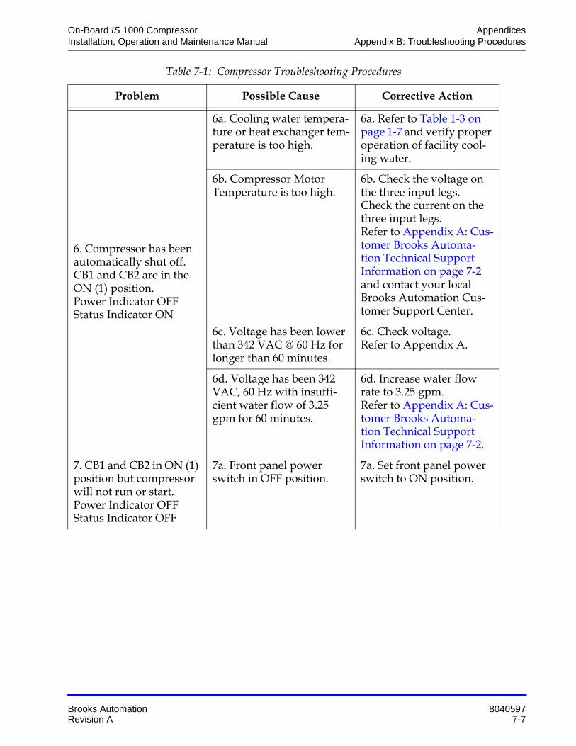
On-Board IS 1000 Compressor Appendices Installation, Operation and Maintenance Manual Appendix B: Troubleshooting Procedures
Brooks Automation 8040597 Revision A 7-7
6. Compressor has been automatically shut off. CB1 and CB2 are in the ON (1) position.Power Indicator OFFStatus Indicator ON
6a. Cooling water tempera-ture or heat exchanger tem-perature is too high.
6a. Refer to Table 1-3 on page 1-7 and verify proper operation of facility cool-ing water.
6b. Compressor Motor Temperature is too high.
6b. Check the voltage on the three input legs.Check the current on the three input legs.Refer to Appendix A: Cus-tomer Brooks Automa-tion Technical Support Information on page 7-2 and contact your local Brooks Automation Cus-tomer Support Center.
6c. Voltage has been lower than 342 VAC @ 60 Hz for longer than 60 minutes.
6c. Check voltage.Refer to Appendix A.
6d. Voltage has been 342 VAC, 60 Hz with insuffi-cient water flow of 3.25 gpm for 60 minutes.
6d. Increase water flow rate to 3.25 gpm.Refer to Appendix A: Cus-tomer Brooks Automa-tion Technical Support Information on page 7-2.
7. CB1 and CB2 in ON (1) position but compressor will not run or start.Power Indicator OFFStatus Indicator OFF
7a. Front panel power switch in OFF position.
7a. Set front panel power switch to ON position.
Table 7-1: Compressor Troubleshooting Procedures
Problem Possible Cause Corrective Action

Appendices On-Board IS 1000 Compressor Appendix B: Troubleshooting Procedures Installation, Operation and Maintenance Manual
8040597 Brooks Automation7-8 Revision A
8. Compressor is run-ning.Power Indicator ONStatus Indicator ON
8a. Cooling water tempera-ture is out of range.
8a. Refer to Appendix A: Customer Brooks Auto-mation Technical Support Information on page 7-2 and verify proper opera-tion of facility cooling water.
8b. Helium Supply/Return pressure ratio is below 150 psig.
8b. Refer to Section 4 and verify OFF Condition Helium System Pressure Verification on page 5-3.
8c. Helium Return pressure is below 100 psig.
8c. Check for loose helium flex line couplings or leaks.
8d. Defective component. 8d. Refer to Appendix A: Customer Brooks Auto-mation Technical Support Information on page 7-2 and contact your local Brooks Automation Cus-tomer Support Center.
Table 7-1: Compressor Troubleshooting Procedures
Problem Possible Cause Corrective Action

On-Board IS 1000 Compressor Appendices Installation, Operation and Maintenance Manual Appendix C: Diagrams
Brooks Automation 8040597 Revision A 7-9
Appendix C: Diagrams

Appendices On-Board IS 1000 Compressor Appendix C: Diagrams Installation, Operation and Maintenance Manual
8040597 Brooks Automation7-10 Revision A
Figure 7-2: On-Board IS 1000 Compressor Helium Flow Diagram
Figure 7-3: On-Board IS 1000 Compressor Electrical Schematic
AA
BB
CC
DD
EE
44
33
22
11
CTI-C
RYOG
ENIC
S
8135
399P
002
Thur
sday
, Jun
e 16
, 200
51
1
HELI
X TE
CHNO
LOGY
COR
PORA
TION
ON-
BOAR
D IS
-100
0 HV
SIZE
CAG
E CO
DEDW
G N
ORE
V
SHEE
TOF
3194
9
ENG
APPV
L
DATE
BY
ENG
APPV
L
ENG
APPV
L
PRE-
PROD
PROD
QA
APPV
L
CHEC
KED
DRAW
N
P
ROPR
IETA
RY N
OTIC
E
EXCE
PT A
S OT
HERW
ISE
AGRE
ED
IN W
RITI
NG, T
HE IN
FORM
ATIO
N
AND
DESI
GN D
ISCL
OSED
HER
EIN
ARE
THE
PROP
ERTY
OF
CTI-C
RYOG
ENIC
S AN
D M
UST
NOT
BE C
OPIE
D OR
DIS
TRIB
UTED
OUTS
IDE
CTI-C
RYOG
ENIC
S
EXCE
PT T
O AU
THOR
IZED
PER
SONS
WIT
H A
GEN
UINE
NEE
D-TO
-KNO
W
WHO
BY
THE
USE
HERE
OF
ACKN
OW
-
LEDG
E CT
I-CRY
OGEN
ICS
OWNE
R-
SHIP
AND
AG
REE
TO M
AINT
AIN
THIS
INFO
RMAT
ION
AND
DESI
GN
IN S
TRIC
T CO
NFID
ENCE
.
EN
VIRO
NMEN
TAL
S
TATE
MEN
T
SELL
ER'S
GOO
DS S
HALL
NOT
BE M
ANUF
ACTU
RED
WIT
H O
R CO
NTAI
N CL
ASS
I ODS
'S A
S DE
FINE
D
UNDE
R SE
CTIO
N 60
2 OF
THE
FEDE
RAL
CLEA
N AI
R
ACT
(42
USC
SECT
ION
7671
A) O
R AN
Y NE
W
APPL
ICAB
LE
REGU
LATI
ONS.
B
P16
K1a
CB2
LT1
LAM
P, 2
4V
C1
T2
CB1
Lock
out r
elay
K1
LT1
Red,
Sta
tus
Indi
cato
r
UNLO
AD S
OLE
NOID
CONT
ACTO
R M1
K1b
M1O
L
OIL
SO
LENO
ID
REVI
SION
S
REV
APPR
OVED
DATE
DESC
RIPT
ION
J16
LT2
Gre
en, P
ump
Run
PM1
PHAS
E M
ONI
TOR
C2
COM
PRES
SOR
MO
L1
C3
IXFM
1
ENL1
3
SW1
M1O
L
M1
1
2
X P3
Y
Z
P2
P1
P4
9596
1
2
C A
R S T
T1 T2 T3
9798
65
4 2
3 1
.02A
TS1
TS2
HeW
ater
Com
p
TS3
XY
ZGN
D
V U
130
°F13
0 °F
06/0
5
GRN/
YEL,
#12
BLK BRN
BLK,
#12
RED
RED,
#12
BLUYEL
BLU
YEL,
#12
RED
BLU
N
WHT/RED
RED
YEL
BLK
BW BW PA BC MR BC JS
01/0
0
01/0
0
01/0
0
01/0
0
01/0
0
01/0
0
01/0
0
01/0
0
01/0
0
BW
HH
W
U
V 12
3P1
4
PS
12
34
56
41
26
53
AB
B A
5
54
6
6
2
21
1
3
3 4
WHT
WHT
3 41 2
1 432
BLK
YEL
82 111 4 105 973 6 12
82 111 4 105 973 6 12
12
12
P2J2
P6J6
J4P4
P10
J10
J5P5
651 74 82 3
74 82 31 65
WHT
WHT
REM
OTE
EMO
2 1
2 1
WHT
/BLU
WHT
/BLU
WHT
WHT
C B A
RED
BLK
C B A
RED
(Hel
2R)
+5 +5
Hel
2
Hel1
R
Hel
1
BLK
CLR W
HT/B
LU
A1A2
ORN
WHT/BLU
WHT
/YEL
WHT/BLU
WHT/BLU
WHT
/BLU
WHT
/BLU
2.5A
NOTE
S: S
HIEL
DING
ON
PRES
SURE
SEN
SE C
ABLE
S AR
E NO
T SH
OWN.
WAT
ER O
UT
WAT
ER IN
P26
J26
P27
J27
RETU
RN P
RESS
URE
SUPP
LY P
RESS
URE
THER
MIST
ER
THER
MIST
ER
Com
pres
sor A
nalo
g In
terfa
ce
Com
pres
sor C
ontro
l Mod
ule
8135
023G
001
1 1
2 2
P11
J11
CLR
P9J9
WHT
/ORN
WHT
/ORN
Rele
ase
per E
CO 1
7233
2
- + + -
WHT/BRN
WHT/BRN
WHT/ORN 2
WHT
/YEL
WHT
/YEL
P15
12
45
K1-C
OM
MO
N3
380-
480
VAC
,50/
60 H
z
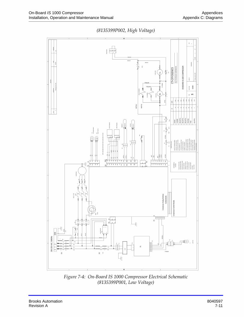
On-Board IS 1000 Compressor Appendices Installation, Operation and Maintenance Manual Appendix C: Diagrams
Brooks Automation 8040597 Revision A 7-11
(8135399P002, High Voltage)
Figure 7-4: On-Board IS 1000 Compressor Electrical Schematic (8135399P001, Low Voltage)
AA
BB
CC
DD
EE
44
33
22
11
6
CTI-C
RYOG
ENIC
S
8135
399P
001
Thur
sday
, Jun
e 16
, 200
51
1
HELI
X TE
CHNO
LOGY
COR
PORA
TION
ON-B
OARD
IS-1
000
COM
PRES
SOR
SIZE
CAG
E CO
DEDW
G N
ORE
V
SHEE
TOF
3194
9
ENG
APPV
L
DATE
BY
ENG
APPV
L
ENG
APPV
L
PRE-
PROD
PROD
QA
APPV
L
CHEC
KED
DRAW
N
P
ROPR
IETA
RY N
OTIC
E
EXCE
PT A
S OT
HERW
ISE
AGRE
ED
IN W
RITI
NG, T
HE IN
FORM
ATIO
N
AND
DESI
GN D
ISCL
OSED
HER
EIN
ARE
THE
PROP
ERTY
OF
CTI-C
RYOG
ENIC
S AN
D M
UST
NOT
BE C
OPIE
D OR
DIS
TRIB
UTED
OUTS
IDE
CTI-C
RYOG
ENIC
S
EXCE
PT T
O AU
THOR
IZED
PER
SONS
WIT
H A
GEN
UINE
NEE
D-TO
-KNO
W
WHO
BY
THE
USE
HERE
OF
ACKN
OW
-
LEDG
E CT
I-CRY
OGEN
ICS
OWNE
R-
SHIP
AND
AG
REE
TO M
AINT
AIN
THIS
INFO
RMAT
ION
AND
DESI
GN
IN S
TRIC
T CO
NFID
ENCE
.
EN
VIRO
NMEN
TAL
S
TATE
MEN
T
SELL
ER'S
GOO
DS S
HALL
NOT
BE M
ANUF
ACTU
RED
WIT
H O
R CO
NTAI
N CL
ASS
I ODS
'S A
S DE
FINE
D
UNDE
R SE
CTIO
N 60
2 OF
THE
FEDE
RAL
CLEA
N AI
R
ACT
(42
USC
SECT
ION
7671
A) O
R AN
Y NE
W
APPL
ICAB
LE
REGU
LATI
ONS.
B
P16
K1
CB2
LT1
LAM
P-24
V
UNLO
AD S
OLE
NOID
LT1
Red,
Sta
tus
Indi
cato
r
CB1
CONT
ACTO
R
M1
OIL
SO
LENO
ID
K1b
M1O
L
J16
REVI
SION
S
REV
APPR
OVED
DATE
DESC
RIPT
ION
LT2
Gre
en, P
ump
Run
PM1
PHAS
E M
ONI
TOR
COM
PRES
SOR
MO
L1
IXFM
1
ENL1
3
M1
K1a
M1O
L
SW1
1
2
X P3
Y
Z
P2
P1
P4
9596
1
2
C A
R S T
T1 T2 T3
65
4 2
3 1
9798
.02A
TS1
TS2
HeW
ater
Com
pTS3
XY
ZG
ND
W U
130
°F13
0 °F
6/16
/05
GRN/
YEL,
#12
BLK BLK
BLK,
#12
RED
RED,
#12
YELYEL
BLU
YEL,
#12
RED
BLU
N
WHT/REDRE
D
YEL
BLK
HH
HH
PA BC MR
BC JS
6/03
01/0
0
01/0
0
01/0
0
01/0
0
01/0
0
6/03
6/03
HH
HH
V
U
V
12
3P1
4
PS
12
34
56
41
26
53
AB
B A
5
54
6
6
2
21
1
3
3 4
WHT
WHT
3 41 2
1 432
BLK
YEL
82 111 4 105 973 6 12
82 111 4 105 973 6 12
12
12
P2J2
P6J6
J4P4
P10
J10
J5P5
651 74 82 3
74 82 31 65
WHTW
HT2 1
2 1
WHT
/BLU
WHT
/BLU
WHT
WHT
C B A
RED
BLK
C B A
RED
(Hel
2R)
+5 +5
Hel2
Hel1
R
Hel
1
BLK
CLR W
HT/Y
EL
WHT
/BLU
A1
A2
ORN
WHT/BLU
WHT
/YEL
WHT/BLU
WHT/BLU
WHT
/BLU
FILTE
R
WHT
/BLU
2.5A
NOTE
S: S
HIEL
DING
ON
PRES
SURE
SEN
SE C
ABLE
S AR
E NO
T SH
OWN.
WAT
ER O
UT
WAT
ER IN
P26
J26
P27
J27
RETU
RN P
RESS
URE
SUPP
LY P
RESS
URE
THER
MIST
ER
THER
MIST
ER
SET
OL T
O 2
1A
Com
pres
sor A
nalo
g In
terfa
ce
Com
pres
sor C
ontro
l Mod
ule
8135
023G
001
1 1
2 2
P11
J11
CLR
P9J9
WHT
/ORN
WHT
/ORN
Rele
ase
per E
CO 1
7233
6
- + + -
WHT/BRN
WHT/ORN
WHT
/YEL
REM
OTE
EM
O
Lock
out r
elay
P15
45
21
3K1
-CO
MM
ON
WHT/BRN
200-
230
VAC,
50/
60H
z

Appendices On-Board IS 1000 Compressor Appendix C: Diagrams Installation, Operation and Maintenance Manual
8040597 Brooks Automation7-12 Revision A
This Page Intentionally Left Blank