omni guard 660 flame detector presentation
TRANSCRIPT

SCP Turbine Flame Detectors (UV)OmniGuard Model 660
Operation & Maintenance
Prepared by :- Mustafa AliReviewed by :- Nabeel Minhaj / Khalil SultanI & C Department (Sawan)

Description Omni Guard 660 Flame Detectors
The Omniguard® 660 Series Flame Detectors are optically based, self-contained, microprocessor controlled, high-speed ultraviolet (UV) flame detectors.
These Flame Detectors are compatible with most alarm panels without the need for a controller. All electronics are housed within a copper free aluminum, high temperature, TGIC-Polyester coated enclosure with a 3/4-14NPT or M20-1.5 conduit entry.
Operation
Flame Detectors are single spectrum detectors utilizing the ultraviolet sensor tube.
Flame Detector requires only that a signal, with in the detection envelope of the UV sensor, be present in a pre-defined strength for a specified time duration.
These parameters are user adjustable and will determine the sensitivity and response time to all fires.
Applications
Flame Detectors are designed for fire detection applications where sudden fires from hydrocarbon fuels or when proper options are selected, from specified non-hydrocarbon fuels, may occur.
These detectors are not recommended for smoldering, or electrical fire hazards.

Standard Features
Microprocessor Based.0 to 60 seconds user adjustable time delays.User adjustable latching or non-latching fire relays.User adjustable sensitivity.User adjustable NO or NC relay outputs.LED indication: fire (red), fault (amber).Transient voltage (surge) protection.
Specifications ( Environmental )
Suitable for use in hazardous locations:Class I, Division 1, Groups B, C & DClass II, Division 1, Groups E, F & GNEMA 4 rated.
Electrical Interface
Nominal voltage input —24VDC(20 Min/32 Max).Maximum allowable ripple voltage — 240mVCurrent Draw (@ 24 VDC):Manual Auto Standby Alarm TestRelay Contact rating (660 High Temperature Model)4 Amps @ 30 VDC (Resistive)Note: Each detector contains two relays:(1) Fire, (1) Fault.
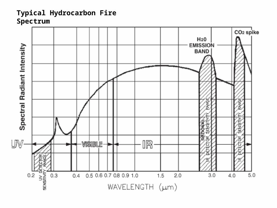
Typical Hydrocarbon Fire Spectrum

Flame Detector Horizontal Field of View
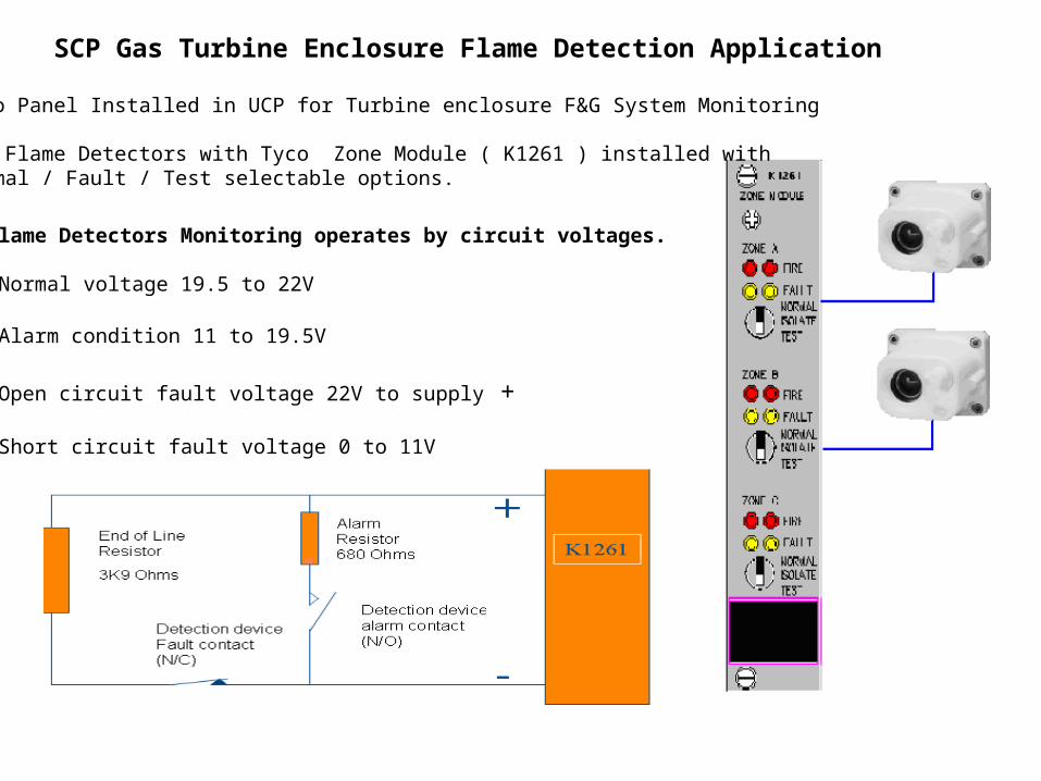
SCP Gas Turbine Enclosure Flame Detection Application
Flame Detectors Monitoring operates by circuit voltages.
•Normal voltage 19.5 to 22V
•Alarm condition 11 to 19.5V
•Open circuit fault voltage 22V to supply +
•Short circuit fault voltage 0 to 11V
Tyco Panel Installed in UCP for Turbine enclosure F&G System Monitoring
Two Flame Detectors with Tyco Zone Module ( K1261 ) installed with Normal / Fault / Test selectable options.
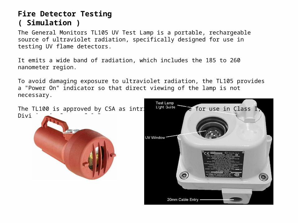
The General Monitors TL105 UV Test Lamp is a portable, rechargeable source of ultraviolet radiation, specifically designed for use in testing UV flame detectors.
It emits a wide band of radiation, which includes the 185 to 260 nanometer region.
To avoid damaging exposure to ultraviolet radiation, the TL105 provides a "Power On" indicator so that direct viewing of the lamp is not necessary.
The TL100 is approved by CSA as intrinsically safe for use in Class I, Division 1, Groups C & D.
Fire Detector Testing ( Simulation )

Maintenance & Troubleshooting
Periodic cleaning of the optical surfaces inessential,
The detectors should be regularly inspected for a build-up of dust or other contaminants on the optical surfaces.
The detection specifications presented in this manual are predicated on performance with clean sensor windows.
Contaminants such as dust, oil and paint will reduce sensitivity. Severe contamination on the light guides or sensor windows will cause a failure of the auto-test. A detector that fails auto-test due to dirty optical surfaces may be capable of detecting fire, but its effectiveness will be limited.
Normal Condition
Flame Detectors are equipped with a fault relay to annunciate a change in the operational status of the detector. When power is applied to the detector, the fault relay will energize within 2 seconds.
A loss of power will cause the relay to de-energize. If the fault relay output fails to change state within 2 seconds after power-up and the amber LED fails to illuminate.
There may be no power reaching the detector’s electronic module. Check the supply voltage, the condition of the fuse located at F1 on the PCB and the wiring to terminals 8 and 10. Also, inspect the wiring to the fault relay terminals 6 and 7 and the jumper JP1 that sets the fault relay option.

Fault Condition
Flame Detectors are equipped with automatic self-test in addition to the manual test. Approximately every 15 minutes, the automatic self-test is actuated and for a brief time interval, the optics and electronics are checked for functionality.
If a detector goes into a fault condition, the optical surfaces should be checked for cleanliness. Clean sensor windows and light guide ends are necessary for the detector (s) to pass self-test.
After the optical surfaces have been inspected and cleaned, reset the detector. If the detector is wired for manual test, perform the manual test. The typical response time should be from 0.6 seconds beyond the actual fire output time delay.
Optical Self-Test
Fire Detectors have a “through-the-lens” optical clarity-checking feature. The factory setting is for automatic test only, switch position 1 is “OFF”, and switch position 2 is “ON”.
If the addition of the manual test feature is desired, then toggle the switch position 1 to “ON”.
If only the manual test feature is needed, then toggle the switch position 1 “ON” and switch position 2 “OFF”.
If no optical testing is preferred, then ensure that both of these switches are “OFF”.

Failure To Alarm
Upon detection of fire, the fire outputs will activate and the red LED, visible through the UV sensor window, will turn “ON”.
If during testing, a detector fails to alarm, inspect the sensor windows for cleanliness. Clean sensor windows are essential for effective optical fire detection.
Should the detector continue to be inoperative, check the supply voltage and all associated wiring.
Alarm Condition - No Fire Present
A detector in alarm condition when no fire is present may be caused by an inadvertent actuation of the manual test.
Verify the light guides are illuminated. If they are, then check the manual test wiring and the test switch for broken, loose, or intermittent connections. Repair or tighten any faulty connections. If the light guides are not illuminated, then contact Omni Guard.
Detection Speed
Flame Detectors Switch position 5 is used to select two detection speeds. The normal speed utilizes a slower sampling rate and automatic self-test interval. The high speed setting increases the data sampling rate and auto self-test frequency.
The normal speed option is the factory setting and recommended for most applications.
Fire Time Delay
Flame Detector The fire outputs can be configured to delay for up to 63 seconds. The factory setting for this delay time is 3 seconds.
To adjust the fire outputs delay time, use Potentiometer (Pot) R49. Turning the Pot counter clock wise (CCW) will decrease the time delay. One turn equals approximately five seconds.
Sensitivity Levels
Flame Detector Switch positions 3 and 4 adjust the sensitivity to four different levels. Level 1 being the most sensitive to UV radiation and the most susceptible to false alarms.
Level 2 is the factory setting and is recommended for most applications.

Relay Adjustments
There are two relays, and Configuration Option Jumpers, JP1 and JP2, located on the exposed surfaceof the printed circuit board (PCB) in the housing assembly. Using these jumpers, the relays may beconfigured as normally open or closed. The factory will ship the detectors with the following settings.
1.) Fire relay (K2) — normally open:-will close when there is a fire present beyond the fire time delay setting.-will close when manual test is activated beyond the length of time for the fire delay time setting.
Note: The red, light emitting diode (LED), will be illuminated when relay transfers.
2.) Fault relay (K1) - normally open:- will close when power is applied (Model 860 after 2 seconds and Model 660 less then a second).- will open when power is lost (or fuse F1 on process PCB is open).- will open when detector fails automatic test.- will open when detector fails manual test.
Note: The amber LED will be illuminated when relay transfers, unless there is a loss of power.
Caution: Upon applying power, insure that the detector remains on for at least 5 seconds to allow for complete initialization to take place.
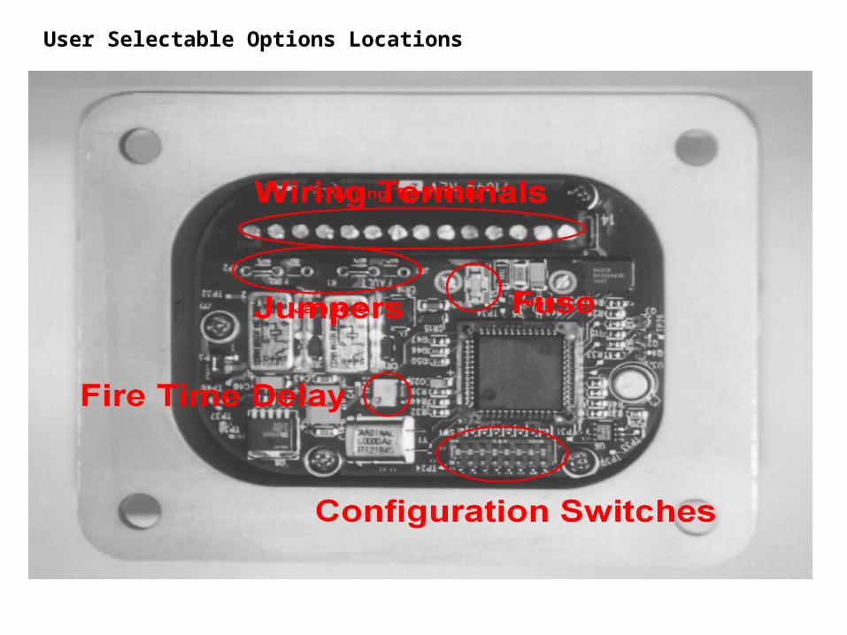
User Selectable Options Locations

Terminal Wiring Identification
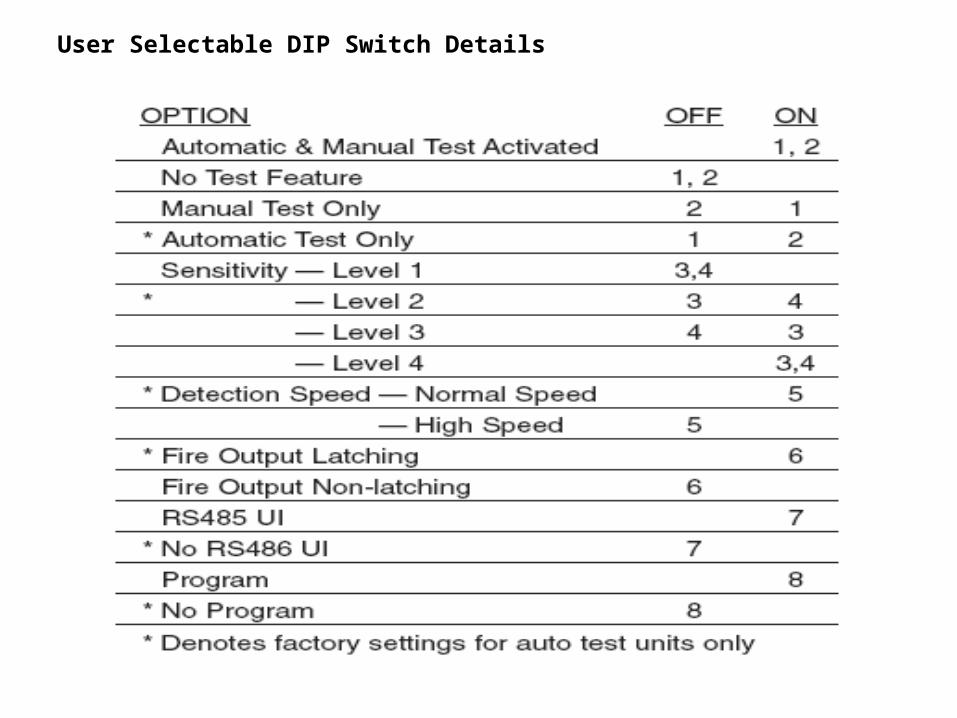
User Selectable DIP Switch Details
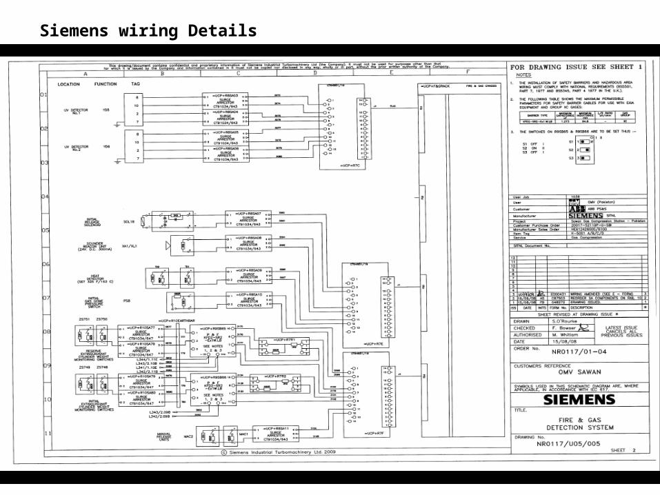
Siemens wiring Details

Tyco F&G Wiring Details