omni-directional vision system for mobile robots...
TRANSCRIPT
Omni-Directional Vision System for Mobile RobotsProposal for Research
Presented to Professor Ricardo Gutierrez-Osunaon
February 5, 2003
byThe A Team
Denise Fancher – Kyle Hoelscher – Michael Layton – Eric Miller
- ii -
Table of Contents
Introduction ............................................................................................................1
Background Information..................................................................................................2
Design Objectives ...........................................................................................................4
Method of Solution .................................................................................................5
Survey of Literature, Market, and Existing Solutions.......................................................5
Design Constraints ..........................................................................................................5
Feasibility Study..............................................................................................................6
Proposed Design Implementation ....................................................................................6
Alternative Solutions..................................................................................................... 12
Design Validation Approach ......................................................................................... 13
Additional Considerations and Analyses ...............................................................15
Economic Analysis........................................................................................................ 15
Societal, Environmental and Safety Analysis................................................................. 18
Proposed Schedule and Work Breakdown ..................................................................... 19
Conclusion............................................................................................................21
References .............................................................................................................. I

- 1 -
Introduction
The A Team proposes the development of an omni-directional vision system for mobile robot
navigation. We will deliver a mobile robot equipped with an imaging system consisting of an
omni-directional mirror and a small video camera. The robot will also be outfitted with an
obstacle detection and avoidance system to prevent collisions.
The primary goal of our project (Phase I) will be the implementation of a video tracking system
to induce our robot to follow a desired target object. The robot will “lock on” to a brightly
colored object which it will then pursue. The robot will move towards the target, constantly
monitoring the target’s position, and if the robot “catches” the target, the robot will stop a
specified distance from the target. The robot should move without colliding with walls or other
obstacles in its path.
We have two options for an expansion phase for our project (Phase II) should time, budget, and
expertise allow us to pursue additional complexity in our system.
1. Interaction of two robot systems in a gaming manner such as tag
This option would require the purchase and fabrication of a second robot and omni-
directional imaging system, after which we could program one robot to “chase” the other
one. The original Phase I robot would “lock on” the new robot and follow it. The Phase
II robot would be programmed to move in the opposite direction from its given target,
and thus the robots would engage in a game of tag. Constraints would be enforced so that
the robots would not actually collide with one another, but instead the game would be
over when the chasing robot gets within a specified distance of its target robot.
2. Remote robotic control system utilizing a live video feed to allow an individual to steer
the robot in any desired direction
- 2 -
This option would allow for a second operational mode to implemented on the original
robot system. A switch or other method for choosing between operating modes would be
added. The original Phase I tracking would be one of the operating modes, and we would
develop an alternative operating mode which would allow a computer user to control the
movements of the robot remotely. The omni-directional image acquired by the robot
would be transmitted back to the computer and unfolded for panoramic viewing. The
user could then see the exact location of the robot and its surroundings, and he could
simply click on a region of the robot’s view to tell the robot to go in that direction. We
would implement an algorithm to convert the coordinates on the user’s view into a format
where we could tell the robot to move in the specified direction.
Background Information
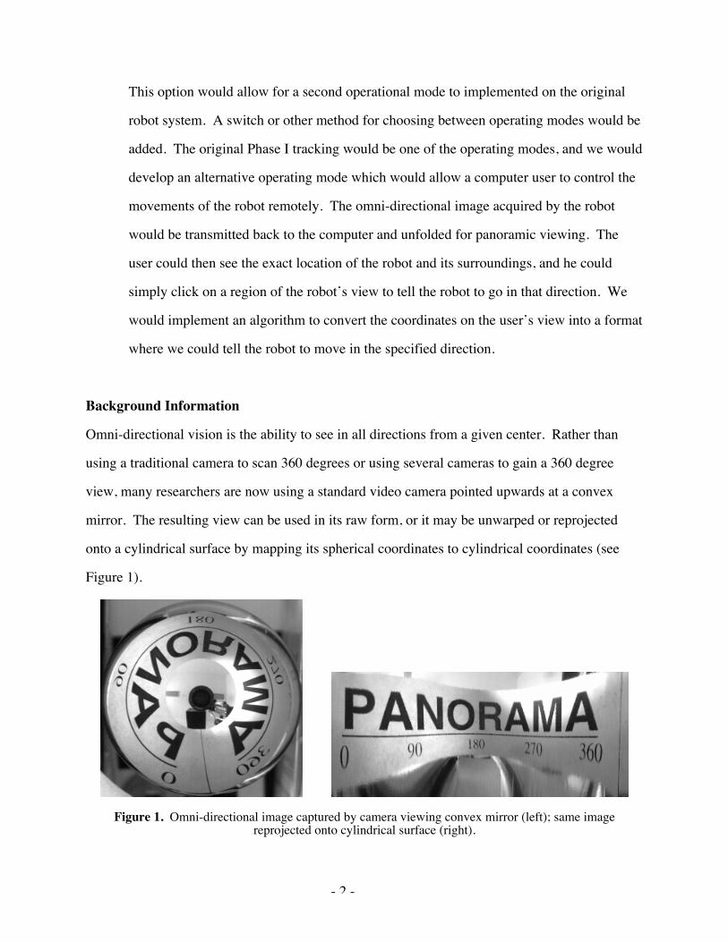
Omni-directional vision is the ability to see in all directions from a given center. Rather than
using a traditional camera to scan 360 degrees or using several cameras to gain a 360 degree
view, many researchers are now using a standard video camera pointed upwards at a convex
mirror. The resulting view can be used in its raw form, or it may be unwarped or reprojected
onto a cylindrical surface by mapping its spherical coordinates to cylindrical coordinates (see
Figure 1).
Figure 1. Omni-directional image captured by camera viewing convex mirror (left); same image
reprojected onto cylindrical surface (right).

- 3 -
Applying omni-directional vision to the field of mobile robotics could yield more efficient and
dexterous robots. A robot with standard single-direction vision may lose a target it is tracking if
the target moves out of the robot’s field of view. The robot would then be forced to stop and
scan for the target before resuming the tracking operation. Omni-directional vision eliminates
this problem by expanding the robot’s field of view to 360 degrees.

- 4 -
Design Objectives
• Gain knowledge of omni-directional and computer imaging and mobile robotics
• Design and construct the omni-directional imaging apparatus for our mobile robot
• Implement software to control the movement of the robot based on omni-directional
images acquired
• Gain experience in the engineering design process including planning, ordering materials,
hardware and software implementation, testing and validation, and delivery
• Practice good project management and planning techniques to ensure delivery of our
project by the end of the semester
- 5 -
Method of Solution
Survey of Literature, Market, and Existing Components
The project advisors provided us with a website that has links to many projects dealing with
omni-directional vision. It was from this site, The Page of Omnidirectional Vision, that we
obtained most of our information.
The current market for omni-directional vision applications includes not only mobile robotics,
but also video surveillance, security, and virtual reality systems.
We know that the Boe-Bot and the CMUcam are compatible because Parallax sells them
together, and we have seen several video clips of these systems in action. Because the sonar and
radio frequency transceivers are all sold as accessories to the Boe-Bot, we know that they work
individually. Other Boe-Bot experiments with cameras, but not omni-directional
Design Constraints
There several limiting constraints that will affect the design and implementation of the omni-
directional vision system for our mobile robot.
• Time – Our project must be completed by the end of the semester.
• Budget – The amount of money we can spend on our project is limited by the professor’s
discretion.
• Component Availability & Shipping Delays – We must use the components that we will
be able to obtain in a timely manner.
• Knowledge – Considering the short time we have studies omni-directional vision and
mobile robotics, our design reflects our basic understanding of these subjects.
• Object Avoidance – The robot must avoid collisions with walls, people, and other
obstacles.
- 6 -
Feasibility Study
We are confident that our components will work together because the hardware has previously
been tested on projects including the CMUcam and the Boe-Bot. The Boe-Bot, coupled with the
BASIC stamp, is a fairly inexpensive combination of a robot and microcontroller. The CMUcam
user manual offers free software for tracking brightly colored objects which will allow us to have
a solid foundation for our new omni-directional software.
Proposed Design Implementation
The omni-visional robot will contain several main hardware components. The following
components are the most feasible components found for constructing an omni-directional
motion-tracking robot. !The Board of Education Robot (Boe-Bot) is the robot chosen for the
project. This parallax made robot will offer a solid platform for fastening the camera while also
providing a moderately simple interface between the BASIC stamp, robot, and the camera. The
BASIC stamp, also developed by parallax, will function as the micro controller. The camera is a
CMU-camera developed by Seattle Robotics. In order to create the omni-directional image, a
hyperbolic mirror manufactured by Neovision will be fastened to the lens of the camera. A
combination of whiskers and sonar devices will be used to prevent the robot from colliding with
other objects.
Basic Stamp
The BASIC stamp (Figure 2) will serve as the micro controller for the project. The stamp will
provide I/O pins, which can be fully programmed to interface with other components such as
LED’s, speakers, and other devices. The stamp will include a 5-volt regulator, resonator, serial
EEPROM, and PBASIC interpreter.

- 7 -
Figure 2. The BASIC stamp.
The EEPROM is a non-volatile memory, which will store the BASIC program received. The
BASIC program will be written using the editor supplied by the parallax vendor and can be
transferred directly from the PC to the EEPROM through the serial connection. Since it is non-
volatile, it will store the program even when power is shut off. The user can erase or write over
the program by reloading a new program into the EEPROM. The PBASIC interpreter will fetch
and write the instructions to the EEPROM.
The BASIC stamp preferred is the BS2p40, which is manufactured by parallax. The BS2P40
provides several advantages over the other Parallax BASIC stamps. This particular stamp offers
16 extra I/O pins. The stamp offers several new commands for interfacing with a larger variety
of components along with a polled interrupt capability feature. The starter kit for the stamp also
offers a serial cable, BASIC stamp manual, thermometer, 4K EEPROM, and a 4.7K resistor,
which can all be useful for the project. The recommended power supply for the stamp is a 7.5 V
DC 1 amp source. The programming language used by the BASIC stamp is the BASIC
programming language. The software loaded into the stamp will be used to control the Boe-Bot.
The stamp will be plugged into the Boe-Bot. The BASIC program software will set up the serial
interface connection between the robot and the CMUcam’s own SX28 micro controller. The
software will instruct the camera to lock onto and track a brightly colored object. The stamp will
command the Boe-Bot to follow the object being tracked based on imaging data sent from the
CMUcam and stop when it comes within a specified distance.

- 8 -
CMU Camera
The CMUcam is a fairly common camera used as for robot vision. The Seattle Robotics
Company manufactures the CMUcam. The CMUcam camera was chosen because it does not
require much power and also can be purchased relatively cheap. A SX28 micro controller is used
for handling all the processing of the camera data. It is connected directly to an OV6620 Omni
vision C-MOS camera chip. Firmware to handle these tasks must be installed to the micro
controller using either a RS-232 or TTL serial port. The serial communication parameters are
specified in Table 1.
Table 1. SX28 Microcontroller Serial Communication Parameters
115,200 Baud8 Data bits1 stop bitNo parity, and No flow Control.
The camera can be used to output information such as the position of a brightly colored object.
The information will be sent to the stamp, which will use the image coordinates to control the
robot and advance to the object. The stamp will send instruction commands to the SX28. Each
command will be sent using visible ASCII characters. When the transmission is successful, an
ACK string will be returned. If the transmission is unsuccessful, a NCK string will be returned.
The commands, located in Table 2, are a sample of common examples used to communicate with
the CMUcam. They will be integrated into the BASIC program downloaded onto the stamp. All
commands will be followed by either an ACK or a NCK reply from the CMUcam notifying
whether or not the transmission was successful.
Table 2. Sample CMUcam Commands

- 9 -
The CMUcam operates at 17 frames per second, which will be sufficient for the project. The
main purpose of the CMUcam will be to lock on a brightly colored object and track it. The
camera will supply the robot with an image and the robot will use the image to gather
coordinates and move to the target. The camera will be pointed vertically straight up with the
hyperbolic mirrors fastened to the lens. This will enable the robot to see a full 360-degree
picture. When tracking a brightly colored object using the CMUcam, it is important to follow
the following calibration procedure:
1. Make sure the camera currently has no objects in front of it.
2. Hold and release the Boe-Bot reset button.
3. After a 1 second delay, the green LED on the CMUcam will turn on for about 5 secondsas the camera adjusts to the lighting.
4. Once the green light turns off, the user will have 5 seconds to place the object in front ofthe robot and allow the robot to lock onto the object.
5. The green light will illuminate again once the robot has locked onto the object.
6. The camera will now track the objects of that particular color.
Command Description\r Sets the camera into an idle state. The camera
should return an ACK acknowledgementCR [ reg1 value1 ]\r This command will set the internal registers of
the camera. The user can send up to 16 register-value combinations. To reset the camera andrestore the camera registers to their default state,simply call this command with no arguments.
DF\r This command will dump a frame out to themicro controller via the serial port. Thisdumped data will consist of raw video datacolumn by column and also consisting of aframe synchronize byte and column synchronizebyte.
L1 value\r This command is used to control the green LEDtracking light. The three possible values are 0,1, and 2. 2 is the default auto mode. 0 disablesthe tracking light and 1 turns the tracking lighton.
DM value\r This command sets the delay before packets thatare transmitted over the serial port. The possibledelay values range from 0-255.

- 10 -
Boe-Bot (Board of Education robot)
The Boe-Bot will require assembly upon arrival from the vendor. The Boe-Bot is built on an
aluminum chassis which will include a breadboard, battery pack, two servos, wheels, along with
other smaller components. The breadboard will offer a platform for connecting other devices
and adding circuitry. The Boe-Bot can be programmed to perform many functions. Once the
assembly has been made, testing must be done to ensure all components work properly. The
Boe-Bot includes two servos or wheel motors which will be used to control the path of the robot.
An electric engine also known as a pulse train will control the servos. The pre-modified servos
will be pulsed in such a way as to control the wheel to turn a full 360 degrees continuously in
either a clockwise or counterclockwise direction. The pulse widths will range between 1 ms and
2 ms. At 1.5 ms pulses, the servo will stay still. At 2 ms pulses, the servo will rotate at full speed
in the counter clockwise direction. Likewise, when the pulses are less than 1.5 ms, the servo will
rotate at a clockwise direction with 1 ms being the fastest speed. The software in the BASIC
stamp will control how much each wheel should turn in order to advance the robot towards the
object that the camera is tracking.
Hyperbolic mirror
A hyperbolic mirror will be needed to accomplish the 360-degree omni visional image. The
mirror chosen will be a half spherical shaped mirror developed by Neovision. The mirror will be
fastened to the lens of the vertically mounted upward CMUcam camera. The lens of the camera
will be located at the focal point of the mirror to ensure that the image will be correct. The
mirror will be made of glass.
Collision prevention
Wires (whiskers) and a sonar device will be fastened to the sides of the robot to help prevent it
from running into walls or other obstacles. The whiskers will allow the robot to avoid obstacles

- 11 -
by touch. The robot will then change direction and continue without colliding into the object.
The whiskers will be wired to the Boe-Bot through the supplied Boe-Bot breadboard. Each
switch circuit I/O pins will use the 10 KW pull-up resistors to monitor their individual voltages.
When the whiskers are free, the voltage at the I/O pin should be around 5 volts. When the
whisker is touched, the line is shorted to ground returning a voltage value of 0 V. The I/O line
will see logic 0 rather than logic 1. The BASIC stamp will be programmed to detect when a
whisker has physical contact with another object. A sonar device will also be used. The sonar
device will send out sonar waves, which will bounce back to the receiver. If an obstacle is in the
sonar path and too close, the receiver will receive the waves quicker than expected and adjust its
path to avoid the obstacle.
Alternative Solutions
There are several alternative solutions to the design problem. One solution would be to use
different types of mirrors. There are three main types of mirrors: conical, parabolic and spherical
(Figure 3). Parabolic is our choice due to the limited distortion of the images. Spherical tends to
warp the image increasingly more, the further away from the camera the image gets. Conical
mirrors tend to reflect the image more downward than straight out from the camera.
Figure 3. Spherical mirror (left) and parabolic mirror(right).

- 12 -
Another alternative solution is to use multiple cameras. Cameras can point in different directions
providing a view of the varying directions. There are several problems with this solution. One
such downfall is the lack of one continuous image. The arrangement produces several different
images instead of one single image. One could stitch the image back together using software,
but this adds a great deal of complexity to the design. Simply having multiple cameras increases
the complexity and also increase the hardware needs of the micro controller. The greatest
downfall of this solution is the escalation in cost. Even inexpensive cameras will cost over $100.
This would quickly put us well over budget.
A third solution is also available. Instead of using mirrors, we would use a super-wide angle
"fish eye" lens. The lens distorts the light entering the lens and provides a large field of view.
This is also an economical solution. The down fall of this alternative, is the relative limited field
of view provided compared to that of the parabolic mirror.
Design Validation Approach
We must fully test the end product in order to insure that the robot and vision system design
match all the appropriate design criteria. For the basic project, we will have to test the entire
vision field to validate that the robot senses and tracks the desired object over the full 360-degree
field. This can be accomplished by moving the desired target completely around the robot faster
than the robot can respond so that it verifies that the target object is never lost.
Moving an object and thus the robot down corridors with trashcans or other objects that may
impede its path can test obstacle avoidance. The sonar and whiskers will have to detect and
navigate the robot away from said object and the vision system will maintain visual contact with
the target at all times. Obstacle avoidance is critical to prevent damage to the robot, camera
system, and external environment.

- 13 -
A standardized checklist may be as follows:
Robot successfully tracks the object in front of robot: �Robot successfully tracks the object on left side: �Robot successfully tracks the object on the right side: �Robot successfully tracks the object from behind: �Rapidly move object from front to back to insure visual tracking system: �Tag a human with the tracking object and move around the building: �

- 14 -
Additional Considerations and Analyses
Economic Analysis
Part Part Number Vendor Cost Quantity Total CostBoe-Bot 28132 Parallax $229.00 1 $229.00CMUcam System 30051 Parallax $139.00 1 $139.00Devantech SRF04Ultrasonic Ranger 28015 Parallax $30.00 1 $30.00Hyperbolic Mirror forOmni-directional Vision H3G Neovision $290.00 1 $290.00
BASIC STAMP upgrade BS2P24-IC Parallax $79.00 1 $79.00Miscellaneous Parts varied Radio Shack / Lowe's $60.00 1 $60.00! ! ! ! ! !
Possible budget additions if expansion projects are taken onPhase II aBoe-Bot 28132 Parallax $229.00 1 $229.00CMUcam System 30051 Parallax $139.00 1 $139.00Devantech SRF04Ultrasonic Ranger 28015 Parallax $30.00 1 $30.00Hyperbolic Mirror forOmni-directional Vision H3G Neovision $290.00 1 $290.00BASIC STAMP upgrade BS2P24-IC Parallax $79.00 1 $79.00Phase II b ! ! ! ! !433.92 MHz Transceiver(SIP/solid/raw) 27997 Parallax $95.00 3 $285.00! ! ! ! ! !! ! Total Cost before expansion = $827.00! ! Total Proposed Cost for Phase IIa = $1,594.00! ! Total Proposed Cost for Phase IIb = $1,112.00
Boe-Bot by Parallax, Inc.
Parallax, Inc provides a lightweight, general robotics and student version of a pre-fabricated
robot known as the Boe-Bot. This robot meets the general design requirements for the specified
project because it is relatively cheap, comes with on-board electronics, and programming
software. The main modifications that will be made to the robot will be in the form of adding
addition hardware and vision components to allow the omni-directional vision system.
- 15 -
Compared to other pre-fabrication robots, the Boe-Bot is the cheapest and most versatile with a
multitude of available accessories from Parallax, Inc.
CMUcam System:
The CMUcam system was originally designed by Carnegie Melon University and is specially
modified by Parallax to seamlessly integrate with the Boe-Bot platform. The connection method
to the robot only requires a couple of screws and plugging in the serial components so that the
stamp onboard the robot can interpret the data sent to it. The CMUcam already contains the
hardware necessary for image tracking, pattern locking onto a specific target, and the interface
necessary for control the wheel servos for movement. With a few modifications, the CMUcam
may be able to lock onto a target of a specified color rather than having to use the pattern lock
feature that is already implemented in the hardware.
Devantech SRF04 Ultrasonic Ranger:
In order to complete the task of obstacle avoidance, the Boe-Bot will have to be outfitted with
electronic whiskers and sonar devices. The whiskers come as part of the Boe-Bot full kit but the
sonar devices have to be purchased separate. Once again, Parallax, Inc. already has sonar
devices on a printed circuit board and ready for integration into the Boe-Bot platform. These
sonar devices have a range of 3cm to 3m, which should allow for plenty of control and collision
detection.
Hyperbolic Mirror for Omni-directional Vision:
In order to achieve the 360-degree field of vision required for the project, we must use some sort
of conical or hyperbolic mirror to reflect a complete image into the camera lens. Through this
reflection, the camera and thus the robot will have a 360-degree field of view in a single frame
shot without the need for camera rotation. Currently, the cheapest vendor for said mirror is

- 16 -
Neovision in the Czech Republic. They can build a 25mm diameter hyperbolic lens, which
would reflect the appropriate image for $290. Compared to other vendors, Neovision presents
the cheapest option as Accowle, Inc. in Japan sells similar mirrors for $430 to $800.
BASIC STAMP upgrade:
Viewing the project description and to allow for the most flexibility and expandability for
design, we have opted to upgrade our stamp package to the BS2P24-IC. This particular stamp
has 19 more BASIC commands, processes approximately 3 times the instructions per second, has
more on-board memory, faster serial port communication speeds, and faster processor speed,
which may be necessary if we take on the expansion phase projects. Essentially, the BS2P24-IC
combines the most functionality and most flexibility for the robot for modest price increase.
Miscellaneous Parts:
The miscellaneous parts heading consists of the numerous pieces necessary to make the Boe-Bot
functional. This budgetary calculation is based on the cost of batteries, protoboards, wires,
solder, mirror mount hardware, and other small pieces necessary to make everything work
together. The reason there is no itemized list of parts and costs is because the mirror itself has
yet to arrive, and thus it is impossible to determine exactly what is needed to mount it properly.
Also, the number of protoboards and wires is completely dependent on how complex the project
becomes as more hardware is custom crafted rather than purchased as plug and play components.
433.92 MHz Transceiver (SIP/solid/raw):
Parallax, Inc. offers transceivers ready built and all that is necessary is to connect the serial port
and power them. If the computer controlled extension is taken, then transceivers for both the
computer and robot(s) would be needed causing the specification for 3 transceivers. These
transceivers have a 2-inch antenna and transmission range of 150 feet. It is noted that in a
budget crunch, a self-built transceiver could be constructed for approximately $28 each but

- 17 -
would require the obtainment of new printed circuit boards or protoboards in order to connect the
transmitter, receiver, and antennae. These materials would be purchased from Reynolds
Electronics in model numbers TWS-434, RWS-434, and 434 MHz for the transmitter, receiver,
and antenna respectively. It must be noted, however, that by custom building this component it
would be much more complex and require more testing time to ensure the construction was done
properly.
Environmental, Societal and Safety Analysis
The environmental concerns associated with our robot and omni-directional vision system are
minimal. The robot itself is small, 127 millimeters in its largest dimension, weighs about three
pounds, and is relatively slow-moving; thus, the danger from impact is negligible.
Power is supplied to the robot in the form of four AAA batteries. Proper disposal of used
batteries is required to ensure environmental safety. The robot and imaging devices include no
other hazardous materials.
The robot will include two sonar units for collision avoidance. The sonar units emit ultrasonic
pulses which will allow the robot to determine its distance from obstacles. While there are no
environmental or safety concerns associated with sonar, it does carry the possibility of interfering
with other sonar devices and delicate equipment, such as in a research environment.
Proposed Schedule and Work Breakdown
We have developed the following Gantt and PERT charts to assist in planning our design.
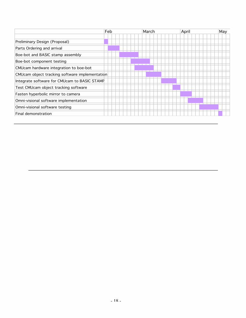
- 18 -
Preliminary Design (Proposal)
Parts Ordering and arrival
Boe-bot and BASIC stamp assembly
Boe-bot component testing
CMUcam hardware integration to boe-bot
CMUcam object tracking software implementation
Integrate software for CMUcam to BASIC STAMP
Test CMUcam object tracking software
Fasten hyperbolic mirror to camera
Omni-visional software implementation
Omni-visional software testing
Final demonstration
Feb March April May

- 19 -
Conclusion
The A Team feels that the requirements proposed in this document for the omni-directional
vision system for the Parallax Boe-Bot can be completed satisfactorily within the next three
months. After careful consideration and deliberation, we have selected all the major components
and are ready to begin purchasing. The Gantt and PERT charts will be valuable tools in assisting
with project scheduling and ensuring we meet our final deadline.
Considering the rarity of omni-visional robot projects, we felt that our project was both
challenging and innovative. The project touched a variety of engineering areas including writing
and testing software, integrating hardware, and understanding optics. The base design allows for
expandability and future experimentation within the omni-directional vision control system
fields. Hopefully with future innovations and research, this particular design can become the
backbone for other researchers’ fields of study.

- I -
References
The Page of Omnidirectional Vision, http://www.cis.upenn.edu/%7Ekostas/omni.html viewed onFebruary 2, 2003.
Seattle Robotics CMUcam Vision System for Boe-Bot User Manual, Carnegie-Mellon University,2002.
CMUcam Vision Board User Manual, Carnegie-Mellon University, 2002.
Robotics! Student Workbook Version 1.5, Parallax, Incorporated, 2001.