omg smart transducer specification (ii) - object management group
TRANSCRIPT

1
© H. Kopetz 06/07/2003 OMG Standard
OMG Smart Transducer Specification (II)
H. KopetzTU WienJuly 2003

2
© H. Kopetz 06/07/2003 OMG Standard
Outline
♦ Introduction♦ Requirements♦ The Interface File System♦ The Transport Protocol♦ Conclusion

3
© H. Kopetz 06/07/2003 OMG Standard
OMG Standard
The DSOS project has cooperated with TTTech Computertechnik, Austria, and Vertel, Cal, USA and the Next TTA project to produce a new standard for smart transducers.The standard has passed all OMG committees and has been formally published at the OMG Website in Jan 2003
Smart Transducer Interface v.1.0
http://www.omg.org
The OMG smart transducer interface is based on the the DSOS Conceptual Model.

4
© H. Kopetz 06/07/2003 OMG Standard
Smart Transducer
A smart transducer consists of the integration of one or more sensor/actuator elements with a microcontroller (possibly on a single silicon die) that provides the following services:♦ signal conditioning♦ calibration and conversion to standard units♦ diagnostic and maintenance♦ real-time network interface
The idiosyncrasies of the particular sensor/actuator element should be hidden behind a standard message interface that supports plug-and-play functionality.

5
© H. Kopetz 06/07/2003 OMG Standard
Advantages of Smart Transducers
! Reduction of the complexity at the system hardware and software and the internal ST failure modes can be hidden from the user by a well-designed fully specified STinterface.
! Cost reduction in installation and maintenance.! No noise pickup from long external signal transmission
lines. ! Better Diagnostics – Simple external ST failure modes
(e.g., fail-silent)! "Plug-and-play" capability if the ST contains its own
documentation on silicon or in an external database.

6
© H. Kopetz 06/07/2003 OMG Standard
Communication Across an Interface
Communication across an interface is only possible, if the participating subsystems share a common set of concepts concerning♦ Syntactic Structure of the information ♦ Meaning of the information chunks (eg., names)♦ Common notion of time and its representation ♦ Access protocol to the information.
A universal smart transducer interfaces must specify thiscommon knowledge.

7
© H. Kopetz 06/07/2003 OMG Standard
Requirements
♦ Composability♦ Minimal jitter♦ Short Error Detection Latency♦ On-Chip Oscillator♦ Plug-and-Play Capability♦ Extremely Low Cost

8
© H. Kopetz 06/07/2003 OMG Standard
Requirement: ComposabilityWe call an architecture composable with respect to a specified property, if the system integration will not invalidate this property provided it has been established at the subsystem level, e.g.:♦ Timeliness♦ Testability
System properties should follow from subsystem properties.
Otherwise the system integrator is left with the challenging task to find out why the system does not work, although all subsystems work according to their specifications.

9
© H. Kopetz 06/07/2003 OMG Standard
Requirement: Small Jitter
Control Model
SensorProcessing Actuator
Control Object (Vehicle)
We must know the exact time difference between observing and acting

10
© H. Kopetz 06/07/2003 OMG Standard
Short Error Detection Latency
There should be a short error detection latency for the detection of♦ Data corruption♦ Failure of a sensor/actuator: This is of particular importance
in systems with a safe state--example power window--safe state is stop.
Fundamental limitations of asynchronous systems -- if I don’t hear anything, I don’t know whether nothing has happened or the system has failed.

11
© H. Kopetz 06/07/2003 OMG Standard
Requirement: On-chip OscillatorIn the future, low-cost microcontrollers will have on-chip oscillators that are very imprecise (+- 50% of nominal frequency) and have a low long-term stability (+- 10% drift/second).Without startup calibration of these oscillators and continuous resynchronization, serial communication is nearly impossible.Consequences:♦ Fieldbus needs a master with a stable time-base.♦ Communication protocol must provide facilities for start-up
synchronization and resynchronization.

12
© H. Kopetz 06/07/2003 OMG Standard
Plug-and-Play Capability
A smart transducer interface must support plug-and-play capabilities♦ Detection of new sensors♦ Sensor identification♦ Access to the configuration information on the Web♦ Configuration of the sensor♦ Integration of the sensor in the running application

13
© H. Kopetz 06/07/2003 OMG Standard
Extremely Low Cost
Smart transducers must be extremely low cost!As a target for the Smart Transducer Interface we were looking for standard 8 bit microcontroller chips that cost less than 0.5 € (in quantities).Hardware footprint:Minimal 2 kbyte of ROM64 bytes of RAM

14
© H. Kopetz 06/07/2003 OMG Standard
The TTA is Waistline Architecture
Basic Services:•TT Transport•Clock Sync•Membership•Fault Isolation
Implementation of basic services is
hidden from the application
Higher-level services:ET TT Transport
DiagnosisGateway
Etc.
Application Software using basic and higher level services
Formally analyzed andvalidated basic servicesare available
Extend the range ofImplementation choicese.g., TT-Ethernet
New high-levelservices to easeapplication development

15
© H. Kopetz 06/07/2003 OMG Standard
System Structure
Gateway
Master Master
Real-TimeBus (TTP/C)fault-tolerant
Backbone Bus to other clusters
Slaves(Sensor,Actuator)
Transducer Bus

16
© H. Kopetz 06/07/2003 OMG Standard
A Smart Transducer Cluster
One active masterUp to 250 slavesCommunication organized in roundsTDMA bus allocation

17
© H. Kopetz 06/07/2003 OMG Standard
Uniform Time Format--OMG Standard
external time format (8 bytes)
Elapsed seconds since January 6, 1980 at00:00(GPS base).
2-24 sec1 sec
Time horizon Time granularitydetermined by
precision of GPS
240 seconds
Start of epoch: January 6, 1980 at 0:00:00 UTCGranularity about 60 nanosecondHorizon 34841 years

18
© H. Kopetz 06/07/2003 OMG Standard
Internal Time Format--limited Horizon and Precision
External time format (8 bytes)
2-24 sec1 sec240 seconds
Horizon Granularity
256 seconds 4 milliseconds
Example of an Internal format (2 byte)
Horizon Granularity

19
© H. Kopetz 06/07/2003 OMG Standard
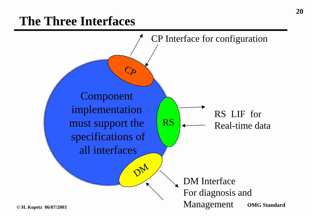
The Three Interfaces of an ST
Real-Time (RS) Service Interface-TT:♦ Contains RT observations♦ Time sensitive♦ In control applications periodic
Diagnostic and Management (DM) Interface-ET ♦ Sporadic Access♦ Requires knowledge about internal s of a node♦ Not time sensitive
Configuration Planning (CP) Interface-ET:♦ Used to install a COTS node into a new configuration♦ Not time sensitive
The Protocol supports each one of these interfaces.
20
© H. Kopetz 06/07/2003 OMG Standard
The Three Interfaces
Component implementation must support the specifications of
all interfaces
CP
DM
RS
CP Interface for configuration
RS LIF for Real-time data
DM InterfaceFor diagnosis andManagement
21
© H. Kopetz 06/07/2003 OMG Standard
Principle of Operation♦ Endpoint of the communication is a record in an Interface File
System (IFS) located in the transducer node.♦ Communication is organized into Rounds
• A round is started by the active master that has knowledge of the global time
• The first frame of a round is a fireworks frame, followed by data frames. The structure of a round is described in the round-descriptor list (RODL).
• every round is independent of every other round♦ The arrival of the fireworks frame is the global
synchronization event starting a new epoch.

22
© H. Kopetz 06/07/2003 OMG Standard
Interface File System (IFS)
♦ Provides the structured name space for the RT images and other node-relevant data (e.g., documentation).
♦ Consists of a set of index-sequential files with constant record length.
♦ Records are protected.♦ The following file operation are supported
• read record• write record• execute record
♦ The configuration information of a round is stored in the file system as a distributed file of a cluster.

23
© H. Kopetz 06/07/2003 OMG Standard
The Three Interfaces
CP
DM
RS
CP Interface for configuration
RS LIF for Real-time data
DM InterfaceFor diagnosis andManagement
InterfaceFile
System (IFS)
LocalProcessesof STD

24
© H. Kopetz 06/07/2003 OMG Standard
Naming
Transducer Node
CORBA-Gateway
Active Master
Active Master
Active Master
Cluster A Cluster B Cluster C
Every record of the IFS can be uniquely identified by the concatenation of Cluster Name, Logical NameFile Name, and Record Name
Up to 250 ClustersUp to 250 NodesUp to 64 FilesUp to 256 Records

25
© H. Kopetz 06/07/2003 OMG Standard
File Operations
The standard supports three operations on an IFS File:♦ Read a Record♦ Write a Record♦ Execute a Record, taking the record contents as a
parameter for the execution
The File Operation is encoded in the remaining two bits of the node internal record name.

26
© H. Kopetz 06/07/2003 OMG Standard
Meta Information
Every smart transducer node contains a class identifier that points to the meta-information and a unique identifier that identifies every sensor in the universe uniquely.The OMG manages the identifier names.The Meta Information about the meaning of the data stored in the IFS is not in the sensor, but on the WEB.At the moment, research is ongoing to formalize parts the meta-information by using XML.
27
© H. Kopetz 06/07/2003 OMG Standard
File Access
Two methods to access a file:♦ Time-Triggered:
• Used for RS Interface• Periodic execution of a preconfigured round. • Round descriptor list RODL can be stored in an
assigned IFS file♦ Event-Triggered:
• Used for CP and DM Interface • Read, write or execute any record within a master slave
round: • the master (client) must form the full address of the
slave record

28
© H. Kopetz 06/07/2003 OMG Standard
Round Types
Multipartner Round (TT):
used for periodic the time-triggered RS Service, reading and writing data of the IFS records containing RT images.Master-Slave Round (ET):
RODL name Data Data Data Data
Record Address Record Data
used for the event-triggered DM and CP service that read andwrite records of the IFS containing calibration, diagnostic andconfiguration data..
Time
Time

29
© H. Kopetz 06/07/2003 OMG Standard
Interleaving of Rounds
Master Slave Rounds have constant frame length.Master Slave Rounds may be empty, if no CM or CP service is requested by the master.
Real Time
MultipartnerRound (TT)
MultipartnerRound (TT)
MultipartnerRound(TT)
Master/SlaveRound(ET)
Master/SlaveRound(ET)
Recommended Schedule:

30
© H. Kopetz 06/07/2003 OMG Standard
Interleaving of Rounds--only TT Rounds
Master Slave Rounds have constant frame length.Master Slave Rounds may be empty, if no CM or CP service is requested by the master.
Real Time
MultipartnerRound (TT)
MultipartnerRound(TT)
MultipartnerRound(TT)
Recommended Schedule:

31
© H. Kopetz 06/07/2003 OMG Standard
Detailed Structure of Round

32
© H. Kopetz 06/07/2003 OMG Standard
Fireworks♦ A fireworks sent by the active master starts a new round.♦ In case of a multipartner round, the fireworks frame
contains a write command and the name of the selected RODL file.
♦ In case of a master-slave round, the firework frame contains the read/write command and the address of the selected record (node name,file name, record name)
♦ The receipt of the fireworks frame is a global synchronization event starting a new epoch.
♦ In case of a master-slave round, the fireworks byte has a regular bit pattern for the synchronization of the slave’s clock (startup synchronization)
♦ There are eight different firework bytes.

33
© H. Kopetz 06/07/2003 OMG Standard
Baptizing of Nodes
In a configuration phase, a new transducer has to be baptized in order to assign a unique 8 bit logical name to each node within a cluster.Baptizing is supported by the Protocol by a binary search algorithm to identify every new sensor.The baptizing and other configuration information is stored in files of the IFS.

34
© H. Kopetz 06/07/2003 OMG Standard
Encoding of ValuesRecommendations for encoding data values:♦ analog data are represented as percentage of selected value
range and standardized in-line error codes.♦ additionally it is possible to transmit an out-of-line
“confidence marker” indicating the confidence of a sensor in its reading.
♦ other data formats and user specified data formats are also supported
♦ standards for the representation are provided

35
© H. Kopetz 06/07/2003 OMG Standard
Physical Layer
For the low speed UART implementation, the following physical layer is recommended:ISO 9141 (in conformance with SAE J1978 and SAE J1850)transmission speed: 10 kbits/s on single wireFor higher speeds, other physical layers can be used (e.g., CAN physical layer).

36
© H. Kopetz 06/07/2003 OMG Standard
Plug and Play
Plug-and-Play Capability can be achieved as follows:♦ Periodically, a request is made to find out if there are any
non-baptized sensors around.♦ If a response is heard, the binary search identifies the
sensor and determines its type.♦ Meta information about the sensor is fetched from the
WEB.♦ The sensor and the application software is reconfigured♦ A new RODL is downloaded into the IFS of the sensors
via the master slave round.♦ The new configuration is started.

37
© H. Kopetz 06/07/2003 OMG Standard
Implementation Experience
The slave part of the protocol has been implemented on different micro controllers (Motorola MC68376, Atmel AT90S2313):♦ UART in software♦ Protocol size, including IFS about 2000 bytes♦ 1.2 msec per byte at 10 kbits/seconds
The master part that provides access to the transducer system via the standard TTA CNI was implemented on a TTP node on the Motorola 68376 microprocessor.

38
© H. Kopetz 06/07/2003 OMG Standard
PCMCIA--Master Controller (i)
FPGAFPGAFPGAFPGA
AVRµC
CAN C
ISO K
RS485
CANBUS
P PPPC CCCM MMM
C CCCI IIIA AAA
I IIIn nnnt ttte eee
r rrrf fffa aaac ccce eee
P PPPC CCCM MMM
C CCCI IIIA AAA
I IIIn nnnt ttte eee
r rrrf fffa aaac ccce eee
FPGAFPGAFPGAFPGA
AVRµC
ISO K
RS485
CAN C CANBUS
Dual-PortedRAM--IFS

39
© H. Kopetz 06/07/2003 OMG Standard
PCMCIA--Master Controller (ii)
Atmel AVR µCFPGA CAN bus
connector
TTP/A bus connector (RS485)
TTP/A bus connector (ISO K)
CAN bus driver
CAN bus controller RS485 driver
ISO K driver
Frontside Backside

40
© H. Kopetz 06/07/2003 OMG Standard
Outlook: Replicated TTP/A Busses
Gateway
Master Master
Real-TimeBus (TTP/C)fault-tolerant
Backbone Bus to other clusters
Slaves(Sensor,Actuator)
Transducer Bus

41
© H. Kopetz 06/07/2003 OMG Standard
Conclusion
♦ Universal Smart Transducer Interface♦ Composability and Testability♦ Standard Interface File System (IFS)♦ Latency Guarantee for Control Applications, Clock
Synchronization better than .1 msec♦ Good Error Detection for fail safe operations♦ Low Cost for intelligent sensors, smallest implementation
less than 2 kbytes of ROM, 64 bytes of RAM (including IFS, software UART at 10 kbits on single wire)
♦ Fault tolerance at system level (duplicated buses)