omen by hp laptop pc - gfk etilizecontent.etilize.com/user-manual/1036237973.pdf · seap windows 10...
TRANSCRIPT

OMEN by HP Laptop PC
Maintenance and Service Guide

© Copyright 2016 HP Development Company, L.P.
NVIDIA and GeForce are trademarks and/or registered trademarks of NVIDIA Corporation in the U.S. and other countries. Bluetooth is a trademark owned by its proprietor and used by HP Inc. under license. Intel and Core are trademarks of Intel Corporation in the U.S. and other countries. Microsoft and Windows are either a registered trademark or trademark of Microsoft Corporation in the United States and/or other countries.
Product notice
This guide describes features that are common to most models. Some features may not be available on your computer.
Not all features are available in all editions or versions of Windows. Systems may require upgraded and/or separately purchased hardware, drivers, software or BIOS update to take full advantage of Windows functionality. Windows 10 is automatically updated, which is always enabled. ISP fees may apply and additional requirements may apply over time for updates. Go to http://www.microsoft.com for details.
The information contained herein is subject to change without notice. The only warranties for HP products and services are set forth in the express warranty statements accompanying such products and services. Nothing herein should be construed as constituting an additional warranty. HP shall not be liable for technical or editorial errors or omissions contained herein.
First Edition: August 2016
Document Part Number: 912139-001

Important Notice about Customer Self-Repair Parts
CAUTION: Your computer includes Customer Self-Repair parts and parts that should only be accessed by an authorized service provider. See Chapter 5, "Removal and replacement procedures for Customer Self-Repair parts," for details. Accessing parts described in Chapter 6, "Removal and replacement procedures for authorized service provider parts," can damage the computer or void your warranty.
iii

iv Important Notice about Customer Self-Repair Parts

Processor information
IMPORTANT: This version of Windows running with the processor or chipsets used in this system has limited support from Microsoft. For more information about Microsoft’s support, please see Microsoft’s Support Lifecycle FAQ at https://support.microsoft.com/lifecycle.
v

vi Processor information

Safety warning notice
WARNING! To reduce the possibility of heat-related injuries or of overheating the device, do not place the device directly on your lap or obstruct the device air vents. Use the device only on a hard, flat surface. Do not allow another hard surface, such as an adjoining optional printer, or a soft surface, such as pillows or rugs or clothing, to block airflow. Also, do not allow the AC adapter to contact the skin or a soft surface, such as pillows or rugs or clothing, during operation. The device and the AC adapter comply with the user-accessible surface temperature limits defined by the International Standard for Safety of Information Technology Equipment (IEC 60950-1).
vii

viii Safety warning notice

Table of contents
1 Product description ....................................................................................................................................... 1
2 External component identification .................................................................................................................. 4
Right side ............................................................................................................................................................... 4
Left side ................................................................................................................................................................. 5
Display .................................................................................................................................................................... 7
Top .......................................................................................................................................................................... 9
TouchPad ............................................................................................................................................. 9
Lights ................................................................................................................................................... 9
Button and speakers ......................................................................................................................... 10
Keys ................................................................................................................................................... 12
Using the action keys ........................................................................................................................ 12
Bottom ................................................................................................................................................................. 14
Rear ...................................................................................................................................................................... 15
Labels ................................................................................................................................................................... 15
3 Illustrated parts catalog .............................................................................................................................. 17
Computer major components .............................................................................................................................. 17
Display assembly subcomponents ...................................................................................................................... 21
Mass storage devices ........................................................................................................................................... 22
Miscellaneous parts ............................................................................................................................................. 23
4 Removal and replacement procedures preliminary requirements .................................................................... 24
Tools required ...................................................................................................................................................... 24
Service considerations ......................................................................................................................................... 24
Plastic parts ....................................................................................................................................... 24
Cables and connectors ...................................................................................................................... 25
Drive handling ................................................................................................................................... 25
Grounding guidelines ........................................................................................................................................... 26
Electrostatic discharge damage ........................................................................................................ 26
Packaging and transporting guidelines .......................................................................... 27
Workstation guidelines ................................................................................................... 27
Equipment guidelines ..................................................................................................... 28
5 Removal and replacement procedures for Customer Self-Repair parts ............................................................. 29
Component replacement procedures .................................................................................................................. 29
ix
Service door ....................................................................................................................................... 29
Memory module ................................................................................................................................ 31
6 Removal and replacement procedures for authorized service provider parts .................................................... 33
Component replacement procedures .................................................................................................................. 33
Base enclosure .................................................................................................................................. 33
Battery ............................................................................................................................................... 35
Hard drive .......................................................................................................................................... 37
SSD (M.2) ........................................................................................................................................... 39
Front speakers ................................................................................................................................... 40
WLAN module .................................................................................................................................... 42
Fans ................................................................................................................................................... 44
Heatsink ............................................................................................................................................. 45
System board .................................................................................................................................... 47
RTC battery ........................................................................................................................................ 51
USB board .......................................................................................................................................... 53
Power button board .......................................................................................................................... 55
Rear speakers .................................................................................................................................... 57
TouchPad board ................................................................................................................................. 59
Power in connector ............................................................................................................................ 61
Display assembly ............................................................................................................................... 63
Camera ............................................................................................................................................... 69
7 Using Setup Utility (BIOS) ............................................................................................................................. 71
Starting Setup Utility (BIOS) ................................................................................................................................ 71
Updating Setup Utility (BIOS) .............................................................................................................................. 71
Determining the BIOS version ........................................................................................................... 71
Downloading a BIOS update .............................................................................................................. 72
8 Using HP PC Hardware Diagnostics (UEFI) ....................................................................................................... 73
Downloading HP PC Hardware Diagnostics (UEFI) to a USB device .................................................................... 73
Additional BIOS crisis recovery tool ..................................................................................................................... 74
9 Backing up, restoring, and recovering ........................................................................................................... 75
Creating recovery media and backups ................................................................................................................ 75
Creating HP Recovery media (select products only) ......................................................................... 75
Using Windows tools ........................................................................................................................................... 76
Restore and recovery ........................................................................................................................................... 77
Recovering using HP Recovery Manager ........................................................................................... 77
What you need to know before you get started ............................................................. 77
x

Using the HP Recovery partition (select products only) ................................................. 78
Using HP Recovery media to recover .............................................................................. 78
Changing the computer boot order ................................................................................ 79
Removing the HP Recovery partition (select products only) ......................................... 80
10 Specifications ............................................................................................................................................ 81
Computer specifications ...................................................................................................................................... 81
43.94 cm (17.3 in) display specifications ............................................................................................................ 82
Hard drive specifications ..................................................................................................................................... 82
11 Power cord set requirements ...................................................................................................................... 83
Requirements for all countries ............................................................................................................................ 83
Requirements for specific countries and regions ................................................................................................ 84
12 Recycling .................................................................................................................................................. 86
Index ............................................................................................................................................................. 87
xi

xii

1 Product description
Category Description
Product Name OMEN by HP Laptop PC
Processors Intel® CoreTM i7-6700HQ (2.6 GHz, turbo up to 3.5 GHz), 2133 MHz/6 MB L3, Quad cTDP 35 W
Intel Core i5-6300HQ (2.3 GHz, turbo up to 3.2 GHz), 2133 MHz/6 MB L3, Quad cTDP 35 W (for use with products with NVIDIA® N17E-G1 graphics only)
Chipset Intel HM170
Graphics Internal graphics:
● Intel HD Graphics 530
NVIDIA graphics:
● NVIDIA N17E-G2 (GeForce® GTX 1070) with up to 8192 MB of dedicated video memory (256 M x 32 GDDR5 x 8 PCs), 8 Gbps VRAM is required
● NVIDIA N17E-G1 (GeForce GTX 1060) with up to 6144 MB of dedicated video memory (256 M x 32 GDDR5 x 6 PCs), 8 Gbps VRAM is required
Supports HD Decode, DX12, and HDMI; Optimus; dynamic switching; and GPU Performance Scaling (GPS), internal and external G-Sync
Virtual Reality support
Panel 43.94 cm (17.3") 16:9 Ultra Wide Aspect Ratio panel:
● Full High Definition (FHD), WLED AntiGlare (1920 x 1080) flat-flat (4.2 mm) UWVA, eDP, typical brightness 300 nits (cd/m2)
● Ultra High Definition (UHD) WLED AntiGlare (3840 x 2160) flat-flat (4.2mm) UWVA, eDP+PSR, typical brightness 300 nits (cd/m2). Bridge panel LCD 17.3 inch UHD (3840x2160) Anti-Glare WLED UWVA 95%cg 300nits eDP 1.3 + PSR flat for cNB", 300nits
Supports eDP1.3+PSR
Memory Two SODIMM slots, customer accessible:
● DDR4-2133 dual channel support (DDR4-2400 bridge to DDR4-2133)
Supports up to 16 GB max system memory with the following:
● 4096 MB (4096 MB x 1)
● 6144 MB (2048 MB x 1 + 4096 MB x 1), no support for 32-bit OS
● 8192 MB (4096 MB x 2) or 8192 MB (8192 MB x 1), no support for 32-bit OS
● 12288 MB (8192 MB +4096 MB), no support for 32-bit OS
● 16384 MB (8192 MB x 2), no support for 32-bit OS or Windows® 7 Home Basic
Hard drive Single HDD configurations:
● 1 TB (7200) 9.5 mm
● 2 TB (5400) 9.5 mm
Hybrid HDD configurations:
● 1 TB 5400 RPM 9.5 mm SSHD with 8 GB NAND
1

Category Description
Dual Storage Configurations:
● 1 TB + 128 GB value solid-state drive (SSD)
● 2 TB + 128 GB value SSD
● 1 TB + 256 GB PCIE SSD
PCIe NVMe (TLC) M.2 SSD:
● 256 GB
● 512 GB
Supports all 7 mm/9.5 mm, SATA 2.5" HDDs
HP 3D DriveGuard
Support for second drive
7 mm and 9.5 mm share the same bracket
Optical drive, external
Supports DVD+/-RW Double-Layer SuperMulti
Supports M-disc
Audio and video Quad speakers
Bang & Olufsen
Supports HP Audio Boost
Supports HP Noise Cancellation
Dual array digital microphones
with appropriate software - beam forming, echo cancellation, noise suppression
Cameras:
● HP Wide Vision HD: HD camera - indicator LED, USB 2.0, BSI sensor, f2.0, 88° WFOV
— 720p by 30 frames per second
● Intel RealSense 3D camera - indicator LED, USB 3.0, 85° WFOV
— 1080p by 30 frames per second, 4x depth resolution
— Supports Windows Hello
Ethernet Integrated 10/100/1000 NIC
Wireless Intel Dual Band Wireless-AC 7265 802.11 ac 2x2 WiFi + Bluetooth® 4.2 Combo Adapter (non vPRO)
Integrated wireless options with dual antenna (M.2/PCIe)
Compatible with Miracast-certified devices, for Windows 10
External media cards
HP Multi-Format Digital Media Card Reader
Supports SD/SDHC/SDXC
Push-Push insertion/removal
Ports Hot Plug / Unplug and auto detect for correct output to wide-aspect vs. standard aspect video (auto adjust panel resolution to fit embedded panel and external monitor connected)
HDMI v2.0 supporting: up to 4096x2160 @ 60 Hz
Headphone / Line out
Microphone input
2 Chapter 1 Product description

Category Description
Mini Dual-Mode DisplayPort
3 USB 3.0 ports (one on right side and two on left side)
RJ-45/Ethernet port
AC Smart Pin adapter plug
Keyboard/pointing devices
Full-size standard 3-coat paint island-style backlit keyboard with numeric keypad in Dragon Red
Clickpad with image sensor
Multitouch gestures enabled
Supports Modern Trackpad Gestures
Taps enabled as default
Power requirements
6-cell Polymer battery – 95.8 Whr
230 W AC adapter with 1.8 M length power cord
Security TPM 2.0
Security lock slot
Operating system
Pre-installed
Windows 10 Professional
Windows 10 Home ML
Windows 10 Home High End ML
Windows 10 Home EM/SL (with i7 processors + 4GB, or, any processors + ≥1080p screen + ≥ 8GB)
Windows 10 Home High End EM/SL/China (with i7 processors + 4GB, or, any processors + ≥1080p screen + ≥ 8GB)
SEAP Windows 10 Home (select products only)
SEAP Windows 10 Home High End (prohibited to Win10 Home with Office 365 AFO OS AVs, and only available to China and 100% attach)
CPPP Windows 10 Home China Language Edition (with i7 processors + 4GB, or, any processors + ≥1080p screen + ≥ 8GB)
Serviceability End user replaceable parts:
AC adapter
Memory
3
2 External component identification
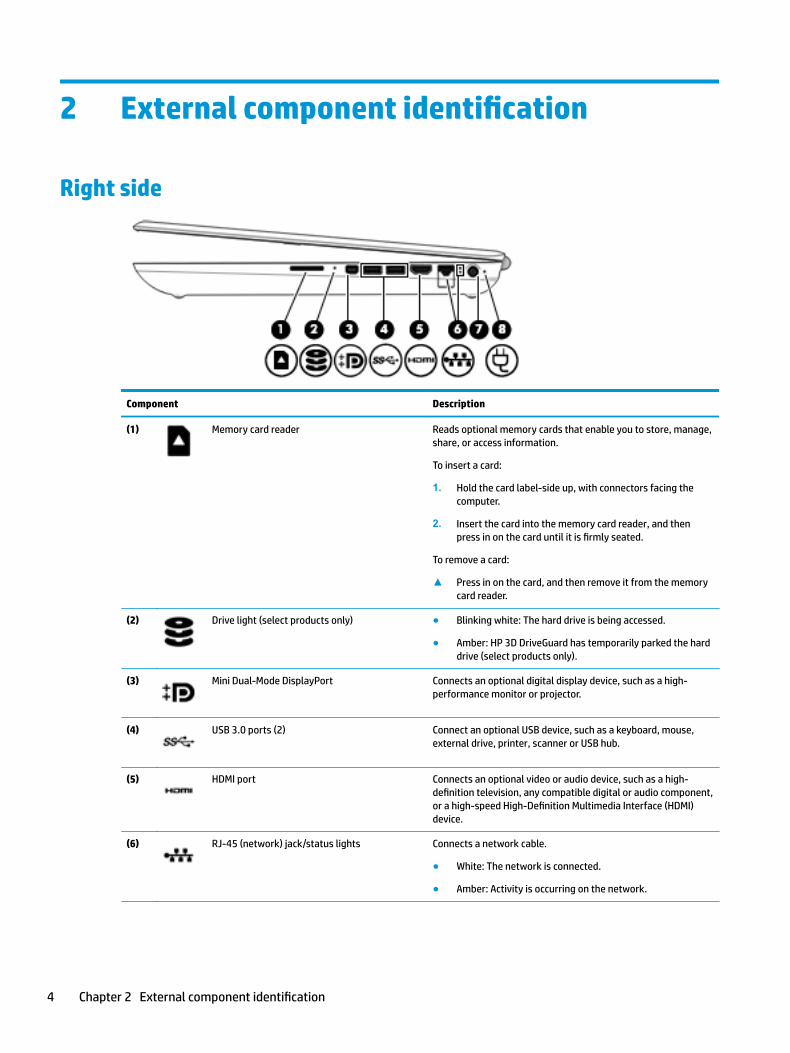
Right side
Component Description
(1) Memory card reader Reads optional memory cards that enable you to store, manage, share, or access information.
To insert a card:
1. Hold the card label-side up, with connectors facing the computer.
2. Insert the card into the memory card reader, and then press in on the card until it is firmly seated.
To remove a card:
▲ Press in on the card, and then remove it from the memory card reader.
(2) Drive light (select products only) ● Blinking white: The hard drive is being accessed.
● Amber: HP 3D DriveGuard has temporarily parked the hard drive (select products only).
(3) Mini Dual-Mode DisplayPort Connects an optional digital display device, such as a high-performance monitor or projector.
(4) USB 3.0 ports (2) Connect an optional USB device, such as a keyboard, mouse, external drive, printer, scanner or USB hub.
(5) HDMI port Connects an optional video or audio device, such as a high-definition television, any compatible digital or audio component, or a high-speed High-Definition Multimedia Interface (HDMI) device.
(6) RJ-45 (network) jack/status lights Connects a network cable.
● White: The network is connected.
● Amber: Activity is occurring on the network.
4 Chapter 2 External component identification
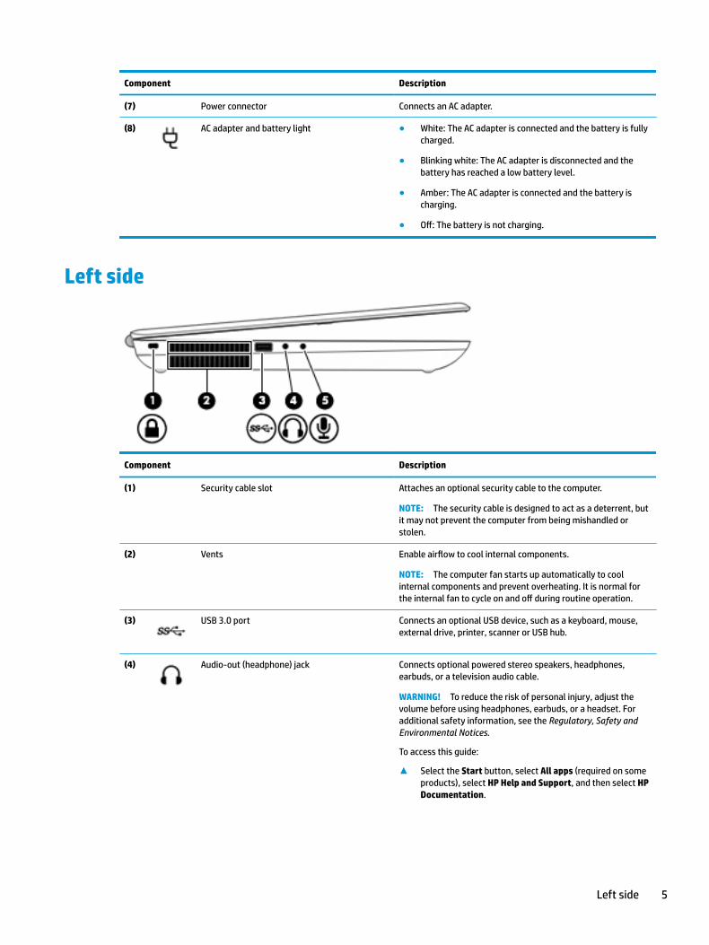
Component Description
(7) Power connector Connects an AC adapter.
(8) AC adapter and battery light ● White: The AC adapter is connected and the battery is fully charged.
● Blinking white: The AC adapter is disconnected and the battery has reached a low battery level.
● Amber: The AC adapter is connected and the battery is charging.
● Off: The battery is not charging.
Left side
Component Description
(1) Security cable slot Attaches an optional security cable to the computer.
NOTE: The security cable is designed to act as a deterrent, but it may not prevent the computer from being mishandled or stolen.
(2) Vents Enable airflow to cool internal components.
NOTE: The computer fan starts up automatically to cool internal components and prevent overheating. It is normal for the internal fan to cycle on and off during routine operation.
(3) USB 3.0 port Connects an optional USB device, such as a keyboard, mouse, external drive, printer, scanner or USB hub.
(4) Audio-out (headphone) jack Connects optional powered stereo speakers, headphones, earbuds, or a television audio cable.
WARNING! To reduce the risk of personal injury, adjust the volume before using headphones, earbuds, or a headset. For additional safety information, see the Regulatory, Safety and Environmental Notices.
To access this guide:
▲ Select the Start button, select All apps (required on some products), select HP Help and Support, and then select HP Documentation.
Left side 5
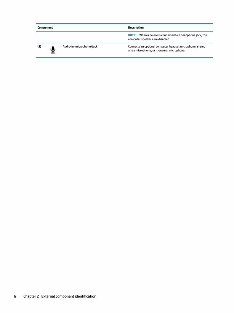
Component Description
NOTE: When a device is connected to a headphone jack, the computer speakers are disabled.
(5) Audio-in (microphone) jack Connects an optional computer headset microphone, stereo array microphone, or monaural microphone.
6 Chapter 2 External component identification

DisplayNOTE: Refer to the illustration that most closely matches your computer.
Component Description
(1) Internal microphones Record sound.
(2) Camera light On: The camera is in use.
(3) Camera Allows you to video chat, record video, and record still images.
(4) WLAN antennas* Send and receive wireless signals to communicate with wireless local area networks (WLANs).
(5) 3D camera light On: The 3D camera is in use.
(6) 3D camera Allows you to video chat and scan or capture 3D images. 3D apps for gaming, security, and immersive collaboration are available to maximize your 3D camera experience.
*The antennas are not visible from the outside of the computer, and antenna location varies. For optimal transmission, keep the areas immediately around the antennas free from obstructions.
For wireless regulatory notices, see the section of the Regulatory, Safety, and Environmental Notices that applies to your country or region.
To access this guide:
▲ Select the Start button, select All apps (required on some products), select HP Help and Support, and then select HP Documentation.
Display 7
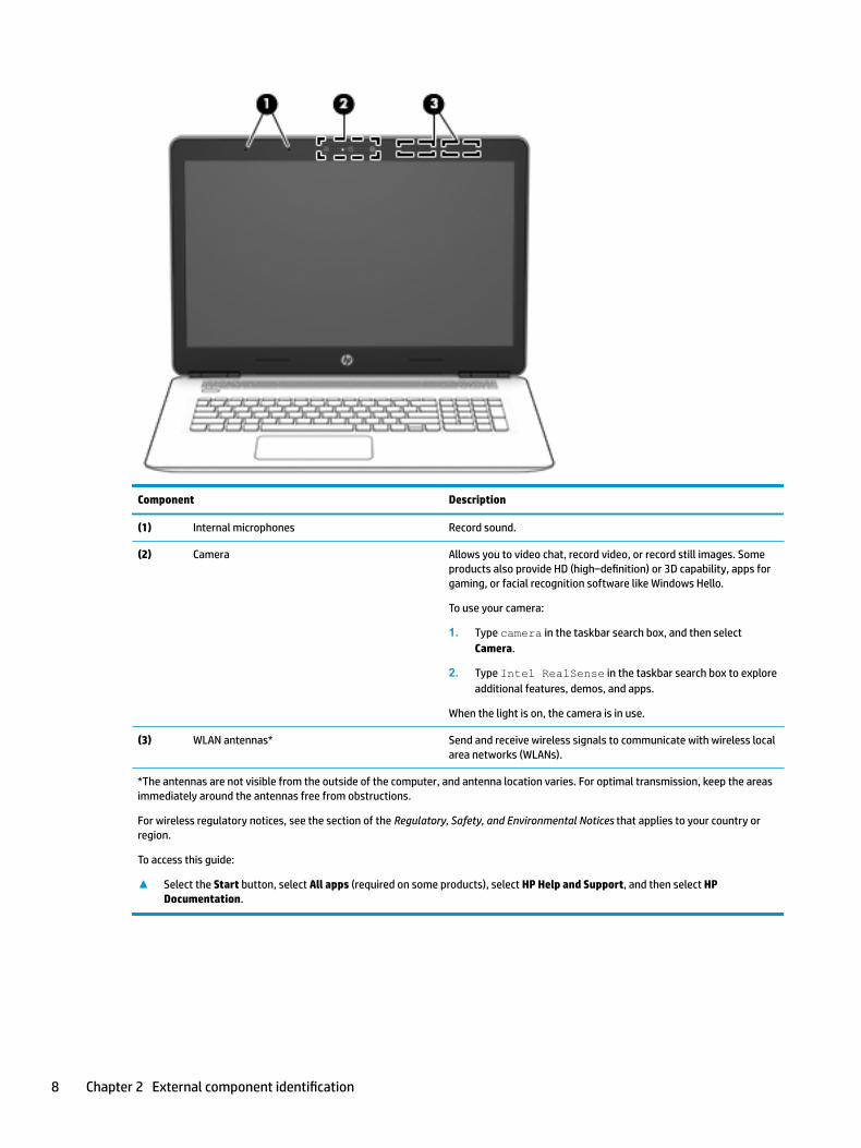
Component Description
(1) Internal microphones Record sound.
(2) Camera Allows you to video chat, record video, or record still images. Some products also provide HD (high–definition) or 3D capability, apps for gaming, or facial recognition software like Windows Hello.
To use your camera:
1. Type camera in the taskbar search box, and then select Camera.
2. Type Intel RealSense in the taskbar search box to explore additional features, demos, and apps.
When the light is on, the camera is in use.
(3) WLAN antennas* Send and receive wireless signals to communicate with wireless local area networks (WLANs).
*The antennas are not visible from the outside of the computer, and antenna location varies. For optimal transmission, keep the areas immediately around the antennas free from obstructions.
For wireless regulatory notices, see the section of the Regulatory, Safety, and Environmental Notices that applies to your country or region.
To access this guide:
▲ Select the Start button, select All apps (required on some products), select HP Help and Support, and then select HP Documentation.
8 Chapter 2 External component identification
Top
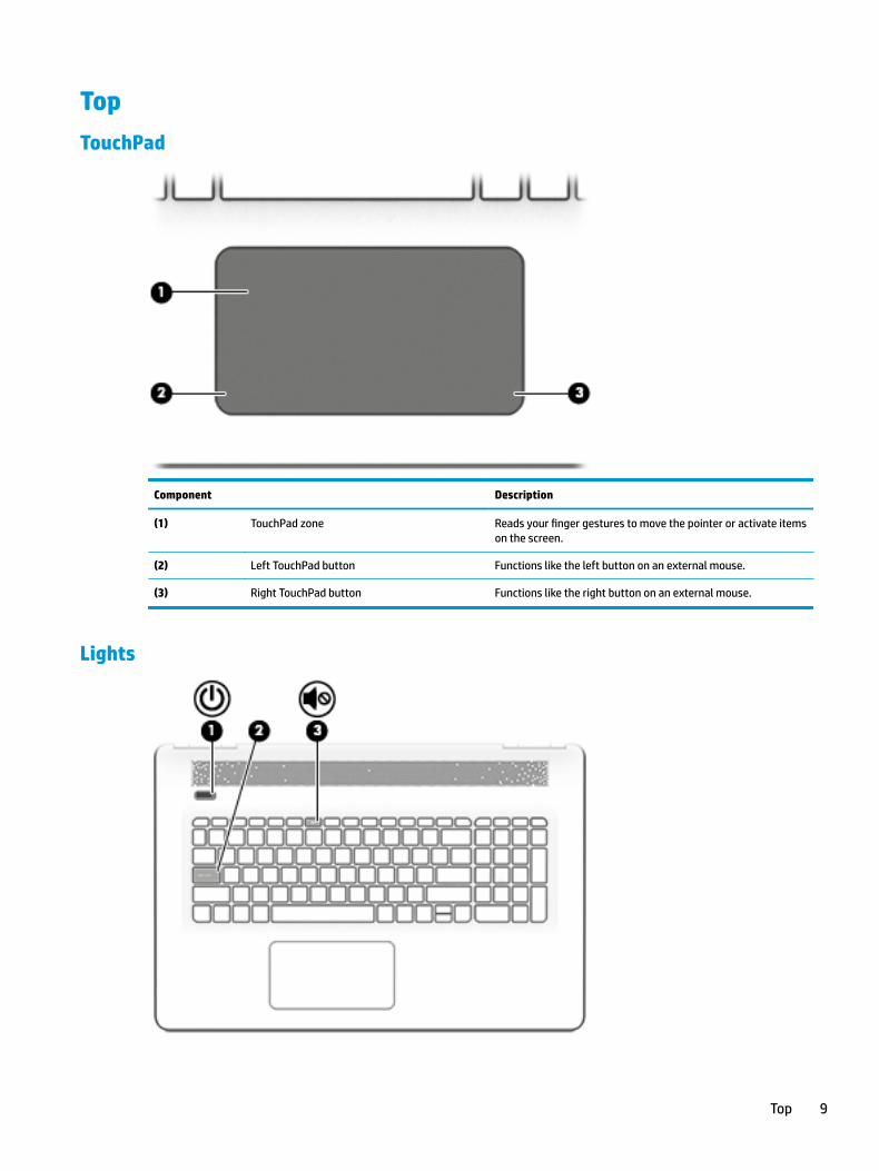
TouchPad
Component Description
(1) TouchPad zone Reads your finger gestures to move the pointer or activate items on the screen.
(2) Left TouchPad button Functions like the left button on an external mouse.
(3) Right TouchPad button Functions like the right button on an external mouse.
Lights
Top 9
Component Description
(1) Power light ● On: The computer is on.
● Blinking: The computer is in the Sleep state, a power-saving state. The computer shuts off power to the display and other unneeded components.
● Off: The computer is off or in Hibernation. Hibernation is a power-saving state that uses the least amount of power.
(2) Caps lock light On: Caps lock is on, which switches the key input to all capital letters.
(3) Mute light ● Amber: Computer sound is off.
● Off: Computer sound is on.
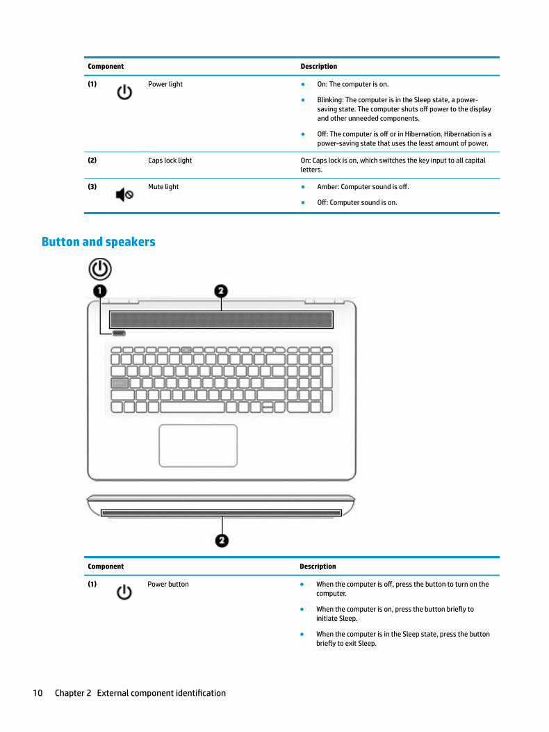
Button and speakers
Component Description
(1) Power button ● When the computer is off, press the button to turn on the computer.
● When the computer is on, press the button briefly to initiate Sleep.
● When the computer is in the Sleep state, press the button briefly to exit Sleep.
10 Chapter 2 External component identification

Component Description
● When the computer is in Hibernation, press the button briefly to exit Hibernation.
CAUTION: Pressing and holding down the power button results in the loss of unsaved information.
If the computer has stopped responding and shutdown procedures are ineffective, press and hold the power button down for at least 5 seconds to turn off the computer.
To learn more about your power settings, see your power options.
▲ Type power in the taskbar search box, and then select Power and sleep settings.
‒ or –
Right-click the Start button, and then select Power Options.
(2) Speakers Produce sound.
Top 11

Keys
Component Description
(1) esc key Displays system information when pressed in combination with the fn key.
(2) fn key Executes specific system functions when pressed in combination with the esc key or the spacebar.
(3) Windows® key Opens the Start menu.
NOTE: Pressing the Windows key again will close the Start menu.
(4) Action keys Execute frequently used system functions.
NOTE: On select products, the f5 action key turns the keyboard backlight feature off or on.
(5) num lock key Alternates between the navigational and numeric functions on the integrated numeric keypad.
(6) Integrated numeric keypad When num lock is on, the keypad can be used like an external numeric keypad.
Using the action keys
● An action key performs an assigned function.
● The icon on each action key illustrates the function for that key.
Icon Description
Opens the Get started app, which provides a broad range of how-to information and troubleshooting tips.
Decreases the screen brightness incrementally as long as you hold down the key.
12 Chapter 2 External component identification
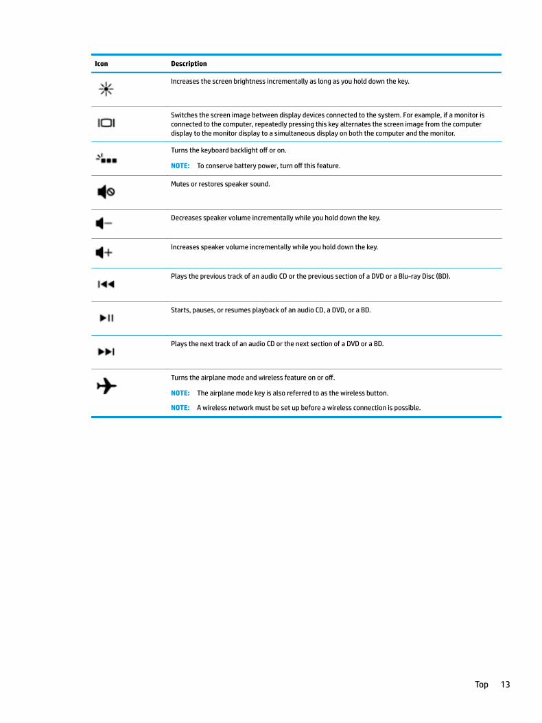
Icon Description
Increases the screen brightness incrementally as long as you hold down the key.
Switches the screen image between display devices connected to the system. For example, if a monitor is connected to the computer, repeatedly pressing this key alternates the screen image from the computer display to the monitor display to a simultaneous display on both the computer and the monitor.
Turns the keyboard backlight off or on.
NOTE: To conserve battery power, turn off this feature.
Mutes or restores speaker sound.
Decreases speaker volume incrementally while you hold down the key.
Increases speaker volume incrementally while you hold down the key.
Plays the previous track of an audio CD or the previous section of a DVD or a Blu-ray Disc (BD).
Starts, pauses, or resumes playback of an audio CD, a DVD, or a BD.
Plays the next track of an audio CD or the next section of a DVD or a BD.
Turns the airplane mode and wireless feature on or off.
NOTE: The airplane mode key is also referred to as the wireless button.
NOTE: A wireless network must be set up before a wireless connection is possible.
Top 13

Bottom
Component Description
(1) Vents Enable airflow to cool internal components.
NOTE: The computer fan starts up automatically to cool internal components and prevent overheating. It is normal for the internal fan to cycle on and off during routine operation.
(2) Service door Provides access to the memory modules.
14 Chapter 2 External component identification

Rear
Component Description
Vent Enables airflow to cool internal components.
NOTE: The computer fan starts up automatically to cool internal components and prevent overheating. It is normal for the internal fan to cycle on and off during routine operation.
LabelsThe labels affixed to the computer provide information you may need when you troubleshoot system problems or travel internationally with the computer.
IMPORTANT: Check the following locations for the labels described in this section: the bottom of the computer, inside the battery bay, under the service door, or on the back of the display.
● Service label—Provides important information to identify your computer. When contacting support, you will probably be asked for the serial number, and possibly for the product number or the model number. Locate these numbers before you contact support.
The service label is located on the bottom of computer.
Rear 15

Component
(1) Model long name (select products only)
(2) Model name (select products only)
(3) Product number
(4) Serial number
(5) Warranty period
● Regulatory label(s)—Provide(s) regulatory information about the computer.
● Wireless certification label(s)—Provide(s) information about optional wireless devices and the approval markings for the countries or regions in which the devices have been approved for use.
16 Chapter 2 External component identification
3 Illustrated parts catalog
Computer major componentsNOTE: HP continually improves and changes product parts. For complete and current information on supported parts for your computer, go to http://partsurfer.hp.com, select your country or region, and then follow the on-screen instructions.
NOTE: Details about your computer, including model, serial number, product key, and length of warranty, are on the service tag at the bottom of your computer. See Labels on page 15 for details.
Computer major components 17

18 Chapter 3 Illustrated parts catalog
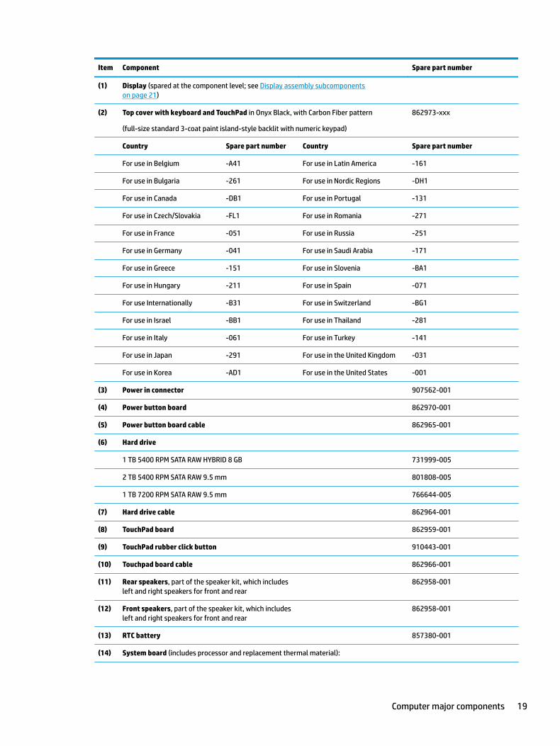
Item Component Spare part number
(1) Display (spared at the component level; see Display assembly subcomponents on page 21)
(2) Top cover with keyboard and TouchPad in Onyx Black, with Carbon Fiber pattern
(full-size standard 3-coat paint island-style backlit with numeric keypad)
862973-xxx
Country Spare part number Country Spare part number
For use in Belgium -A41 For use in Latin America -161
For use in Bulgaria -261 For use in Nordic Regions -DH1
For use in Canada -DB1 For use in Portugal -131
For use in Czech/Slovakia -FL1 For use in Romania -271
For use in France -051 For use in Russia -251
For use in Germany -041 For use in Saudi Arabia -171
For use in Greece -151 For use in Slovenia -BA1
For use in Hungary -211 For use in Spain -071
For use Internationally -B31 For use in Switzerland -BG1
For use in Israel -BB1 For use in Thailand -281
For use in Italy -061 For use in Turkey -141
For use in Japan -291 For use in the United Kingdom -031
For use in Korea -AD1 For use in the United States -001
(3) Power in connector 907562-001
(4) Power button board 862970-001
(5) Power button board cable 862965-001
(6) Hard drive
1 TB 5400 RPM SATA RAW HYBRID 8 GB 731999-005
2 TB 5400 RPM SATA RAW 9.5 mm 801808-005
1 TB 7200 RPM SATA RAW 9.5 mm 766644-005
(7) Hard drive cable 862964-001
(8) TouchPad board 862959-001
(9) TouchPad rubber click button 910443-001
(10) Touchpad board cable 862966-001
(11) Rear speakers, part of the speaker kit, which includes left and right speakers for front and rear
862958-001
(12) Front speakers, part of the speaker kit, which includes left and right speakers for front and rear
862958-001
(13) RTC battery 857380-001
(14) System board (includes processor and replacement thermal material):
Computer major components 19
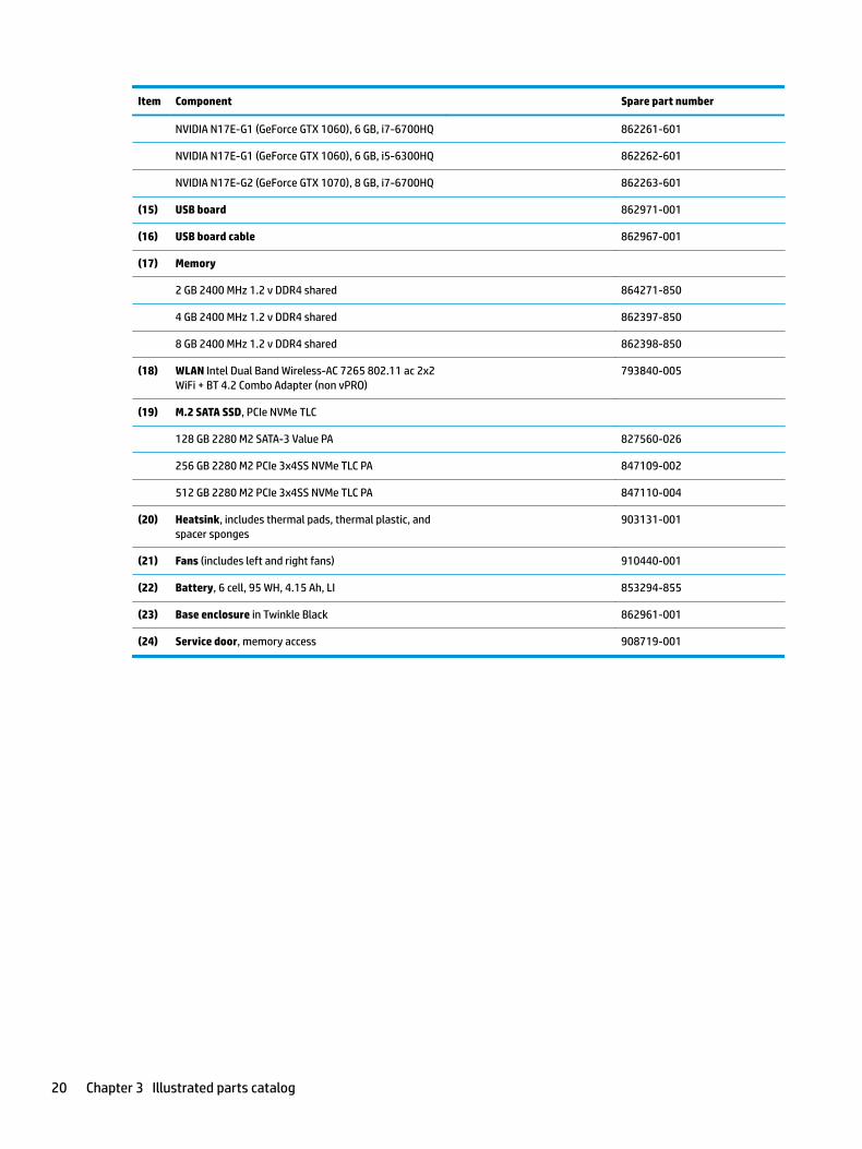
Item Component Spare part number
NVIDIA N17E-G1 (GeForce GTX 1060), 6 GB, i7-6700HQ 862261-601
NVIDIA N17E-G1 (GeForce GTX 1060), 6 GB, i5-6300HQ 862262-601
NVIDIA N17E-G2 (GeForce GTX 1070), 8 GB, i7-6700HQ 862263-601
(15) USB board 862971-001
(16) USB board cable 862967-001
(17) Memory
2 GB 2400 MHz 1.2 v DDR4 shared 864271-850
4 GB 2400 MHz 1.2 v DDR4 shared 862397-850
8 GB 2400 MHz 1.2 v DDR4 shared 862398-850
(18) WLAN Intel Dual Band Wireless-AC 7265 802.11 ac 2x2 WiFi + BT 4.2 Combo Adapter (non vPRO)
793840-005
(19) M.2 SATA SSD, PCIe NVMe TLC
128 GB 2280 M2 SATA-3 Value PA 827560-026
256 GB 2280 M2 PCIe 3x4SS NVMe TLC PA 847109-002
512 GB 2280 M2 PCIe 3x4SS NVMe TLC PA 847110-004
(20) Heatsink, includes thermal pads, thermal plastic, and spacer sponges
903131-001
(21) Fans (includes left and right fans) 910440-001
(22) Battery, 6 cell, 95 WH, 4.15 Ah, LI 853294-855
(23) Base enclosure in Twinkle Black 862961-001
(24) Service door, memory access 908719-001
20 Chapter 3 Illustrated parts catalog

Display assembly subcomponents
Item Component Spare part number
(1) Display bezel
For products with 3D camera 857451-001
For products with HD camera 857450-001
(2) Microphone board 862969-001
(3) Camera
3D camera 781624-005
HD camera 846006-003
(4) 43.94 cm (17.3”) raw panel
● Non-touch screen, FHD, AG, UWVA, 300 eDP, Flat, G-Sync 903815-001
● Non-touch screen, UHD, AG, UWVA, 300 eDP, 1.3PSR, Flat, G-Sync 903816-001
Display assembly subcomponents 21
Item Component Spare part number
(5) Hinge kit (includes left and right hinges) 862956-001
Hinge caps 862955-001
(6) Display cable
For products with non-touch FHD screen and HD camera 857456-001
For products with non-touch FHD screen and 3D camera 857458-001
For products with non-touch UHD screen and HD camera 857459-001
For products with non-touch UHD screen and 3D camera 857461-001
(7) Dual antennas 857443-001
(8) HD camera frame 857475-001
(9) Back cover in Shadow Mesh, includes dual antenna 862968-001
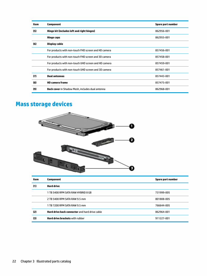
Mass storage devices
Item Component Spare part number
(1) Hard drive
1 TB 5400 RPM SATA RAW HYBRID 8 GB 731999-005
2 TB 5400 RPM SATA RAW 9.5 mm 801808-005
1 TB 7200 RPM SATA RAW 9.5 mm 766644-005
(2) Hard drive back connector and hard drive cable 862964-001
(3) Hard drive brackets with rubber 911227-001
22 Chapter 3 Illustrated parts catalog

Miscellaneous parts
Component Spare part number
AC adapter, 230 W PFC, Smart, slim, 4.5 mm 693706-001
External USB ODD, DVD+/-RW DL SuperMulti, 9.5 mm tray load, SATA 747080-001
HDMI to VGA adapter 701943-001
Power cord (black, 1.8 m):
For use in Australia and New Zealand 100661-001
For use in China 286496-001
For use in Denmark 130627-008
For use in Europe 100614-009
For use in Japan 653326-001
For use in Israel 398062-001
For use in North America and Latin America 121565-001
For use in South Africa 187487-005
For use in South Korea 231216-001
For use in Switzerland 150304-008
For use in Thailand 285052-001
For use in the United Kingdom and Singapore 100613-008
Screw covers 912492-001
Screw kit 862957-001
Miscellaneous parts 23
4 Removal and replacement procedures preliminary requirements
Tools requiredYou will need the following tools to complete the removal and replacement procedures:
● Flat-bladed screwdriver
● Magnetic screwdriver
● Phillips P0 and P1 screwdrivers
Service considerationsThe following sections include some of the considerations that you must keep in mind during disassembly and assembly procedures.
NOTE: As you remove each subassembly from the computer, place the subassembly (and all accompanying screws) away from the work area to prevent damage.
Plastic parts
CAUTION: Using excessive force during disassembly and reassembly can damage plastic parts. Use care when handling the plastic
24 Chapter 4 Removal and replacement procedures preliminary requirements
Cables and connectors
CAUTION: When servicing the computer, be sure that cables are placed in their proper locations during the reassembly process. Improper cable placement can damage the computer.
Cables must be handled with extreme care to avoid damage. Apply only the tension required to unseat or seat the cables during removal and insertion. Handle cables by the connector whenever possible. In all cases, avoid bending, twisting, or tearing cables. Be sure that cables are routed in such a way that they cannot be caught or snagged by parts being removed or replaced. Handle flex cables with extreme care; these cables tear easily.
Drive handling
CAUTION: Drives are fragile components that must be handled with care. To prevent damage to the computer, damage to a drive, or loss of information, observe these precautions:
Before removing or inserting a hard drive, shut down the computer. If you are unsure whether the computer is off or in Hibernation, turn the computer on, and then shut it down through the operating system.
Before handling a drive, be sure that you are discharged of static electricity. While handling a drive, avoid touching the connector.
Before removing an optical drive, be sure that a disc is not in the drive and be sure that the optical drive tray is closed.
Handle drives on surfaces covered with at least one inch of shock-proof foam.
Avoid dropping drives from any height onto any surface.
After removing a hard drive or an optical drive, place it in a static-proof bag.
Avoid exposing an internal hard drive to products that have magnetic fields, such as monitors or speakers.
Avoid exposing a drive to temperature extremes or liquids.
If a drive must be mailed, place the drive in a bubble pack mailer or other suitable form of protective packaging and label the package “FRAGILE.”
Service considerations 25
Grounding guidelines
Electrostatic discharge damage
Electronic components are sensitive to electrostatic discharge (ESD). Circuitry design and structure determine the degree of sensitivity. Networks built into many integrated circuits provide some protection, but in many cases, ESD contains enough power to alter device parameters or melt silicon junctions.
A discharge of static electricity from a finger or other conductor can destroy static-sensitive devices or microcircuitry. Even if the spark is neither felt nor heard, damage may have occurred.
An electronic device exposed to ESD may not be affected at all and can work perfectly throughout a normal cycle. Or the device may function normally for a while, then degrade in the internal layers, reducing its life expectancy.
CAUTION: To prevent damage to the computer when you are removing or installing internal components, observe these precautions:
Keep components in their electrostatic-safe containers until you are ready to install them.
Before touching an electronic component, discharge static electricity by using the guidelines described in this section.
Avoid touching pins, leads, and circuitry. Handle electronic components as little as possible.
If you remove a component, place it in an electrostatic-safe container.
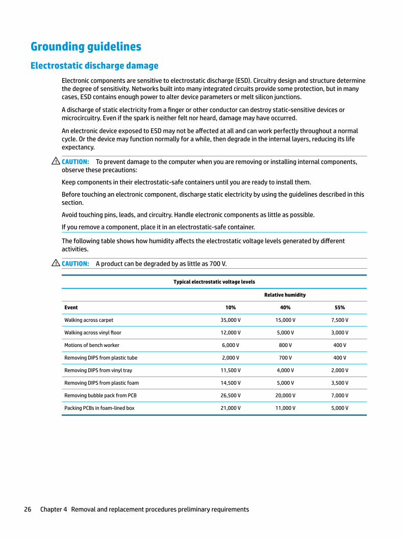
The following table shows how humidity affects the electrostatic voltage levels generated by different activities.
CAUTION: A product can be degraded by as little as 700 V.
Typical electrostatic voltage levels
Relative humidity
Event 10% 40% 55%
Walking across carpet 35,000 V 15,000 V 7,500 V
Walking across vinyl floor 12,000 V 5,000 V 3,000 V
Motions of bench worker 6,000 V 800 V 400 V
Removing DIPS from plastic tube 2,000 V 700 V 400 V
Removing DIPS from vinyl tray 11,500 V 4,000 V 2,000 V
Removing DIPS from plastic foam 14,500 V 5,000 V 3,500 V
Removing bubble pack from PCB 26,500 V 20,000 V 7,000 V
Packing PCBs in foam-lined box 21,000 V 11,000 V 5,000 V
26 Chapter 4 Removal and replacement procedures preliminary requirements

Packaging and transporting guidelines
Follow these grounding guidelines when packaging and transporting equipment:
● To avoid hand contact, transport products in static-safe tubes, bags, or boxes.
● Protect ESD-sensitive parts and assemblies with conductive or approved containers or packaging.
● Keep ESD-sensitive parts in their containers until the parts arrive at static-free workstations.
● Place items on a grounded surface before removing items from their containers.
● Always be properly grounded when touching a component or assembly.
● Store reusable ESD-sensitive parts from assemblies in protective packaging or nonconductive foam.
● Use transporters and conveyors made of antistatic belts and roller bushings. Be sure that mechanized equipment used for moving materials is wired to ground and that proper materials are selected to avoid static charging. When grounding is not possible, use an ionizer to dissipate electric charges.
Workstation guidelines
Follow these grounding workstation guidelines:
● Cover the workstation with approved static-shielding material.
● Use a wrist strap connected to a properly grounded work surface and use properly grounded tools and equipment.
● Use conductive field service tools, such as cutters, screwdrivers, and vacuums.
● When fixtures must directly contact dissipative surfaces, use fixtures made only of static safe materials.
● Keep the work area free of nonconductive materials, such as ordinary plastic assembly aids and plastic foam.
● Handle ESD-sensitive components, parts, and assemblies by the case or PCM laminate. Handle these items only at static-free workstations.
● Avoid contact with pins, leads, or circuitry.
● Turn off power and input signals before inserting or removing connectors or test equipment.
Grounding guidelines 27

Equipment guidelines
Grounding equipment must include either a wrist strap or a foot strap at a grounded workstation.
● When seated, wear a wrist strap connected to a grounded system. Wrist straps are flexible straps with a minimum of one megohm ±10% resistance in the ground cords. To provide proper ground, wear a strap snugly against the skin at all times. On grounded mats with banana-plug connectors, use alligator clips to connect a wrist strap.
● When standing, use foot straps and a grounded floor mat. Foot straps (heel, toe, or boot straps) can be used at standing workstations and are compatible with most types of shoes or boots. On conductive floors or dissipative floor mats, use foot straps on both feet with a minimum of one megohm resistance between the operator and ground. To be effective, the conductive equipment must be worn in contact with the skin.
The following grounding equipment is recommended to prevent electrostatic damage:
● Antistatic tape
● Antistatic smocks, aprons, and sleeve protectors
● Conductive bins and other assembly or soldering aids
● Nonconductive foam
● Conductive tabletop workstations with ground cords of one megohm resistance
● Static-dissipative tables or floor mats with hard ties to the ground
● Field service kits
● Static awareness labels
● Material-handling packages
● Nonconductive plastic bags, tubes, or boxes
● Metal tote boxes
● Electrostatic voltage levels and protective materials
The following table lists the shielding protection provided by antistatic bags and floor mats.
Material Use Voltage protection level
Antistatic plastics Bags 1,500 V
Carbon-loaded plastic Floor mats 7,500 V
Metallized laminate Floor mats 5,000 V
28 Chapter 4 Removal and replacement procedures preliminary requirements
5 Removal and replacement procedures for Customer Self-Repair parts
This chapter provides removal and replacement procedures for Customer Self-Repair parts.
NOTE: The Customer Self-Repair program is not available in all locations. Installing a part not supported by the Customer Self-Repair program may void your warranty. Check your warranty to determine if Customer Self-Repair is supported in your location.
Component replacement proceduresNOTE: Details about your computer, including model, serial number, product key, and length of warranty, are on the service tag at the bottom of your computer. See Labels on page 15 for details.
NOTE: HP continually improves and changes product parts. For complete and current information on supported parts for your computer, go to http://partsurfer.hp.com, select your country or region, and then follow the on-screen instructions.
There are two screws that must be removed, replaced, and/or loosened when servicing Customer Self-Repair parts. Make special note of the screw sizes and locations during removal and replacement.
Service door
Description Spare part number
Service door, memory access 908719-001
Before removing the service door, follow these steps:
1. Turn off the computer. If you are unsure whether the computer is off or in Hibernation, turn the computer on, and then shut it down through the operating system.
2. Disconnect the power from the computer by first unplugging the power cord from the AC outlet and then unplugging the AC adapter from the computer.
3. Disconnect all external devices from the computer.
Remove the service door:
1. Release the two captive Phillips screws (1) securing the service door to the base enclosure.
Component replacement procedures 29

2. Insert a thin plastic tool around the service door to release the clips, and then lift the service door (2) to remove it.
Reverse this procedure to replace the service door.
30 Chapter 5 Removal and replacement procedures for Customer Self-Repair parts
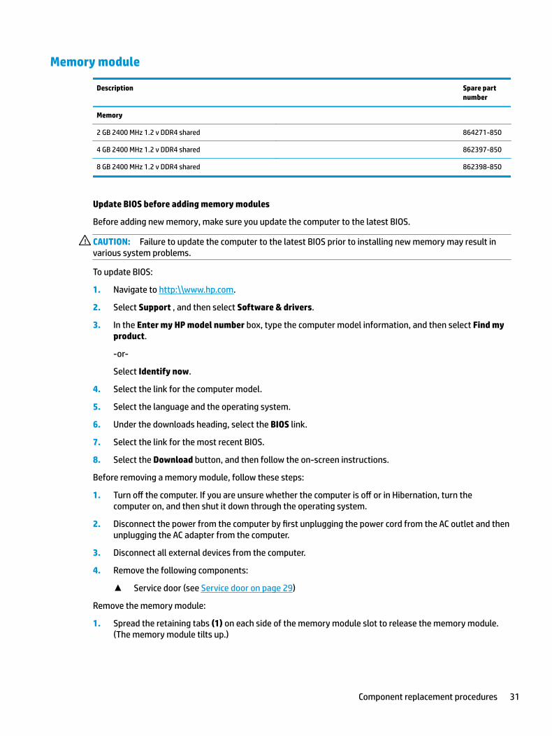
Memory module
Description Spare part number
Memory
2 GB 2400 MHz 1.2 v DDR4 shared 864271-850
4 GB 2400 MHz 1.2 v DDR4 shared 862397-850
8 GB 2400 MHz 1.2 v DDR4 shared 862398-850
Update BIOS before adding memory modules
Before adding new memory, make sure you update the computer to the latest BIOS.
CAUTION: Failure to update the computer to the latest BIOS prior to installing new memory may result in various system problems.
To update BIOS:
1. Navigate to http:\\www.hp.com.
2. Select Support , and then select Software & drivers.
3. In the Enter my HP model number box, type the computer model information, and then select Find my product.
-or-
Select Identify now.
4. Select the link for the computer model.
5. Select the language and the operating system.
6. Under the downloads heading, select the BIOS link.
7. Select the link for the most recent BIOS.
8. Select the Download button, and then follow the on-screen instructions.
Before removing a memory module, follow these steps:
1. Turn off the computer. If you are unsure whether the computer is off or in Hibernation, turn the computer on, and then shut it down through the operating system.
2. Disconnect the power from the computer by first unplugging the power cord from the AC outlet and then unplugging the AC adapter from the computer.
3. Disconnect all external devices from the computer.
4. Remove the following components:
▲ Service door (see Service door on page 29)
Remove the memory module:
1. Spread the retaining tabs (1) on each side of the memory module slot to release the memory module. (The memory module tilts up.)
Component replacement procedures 31
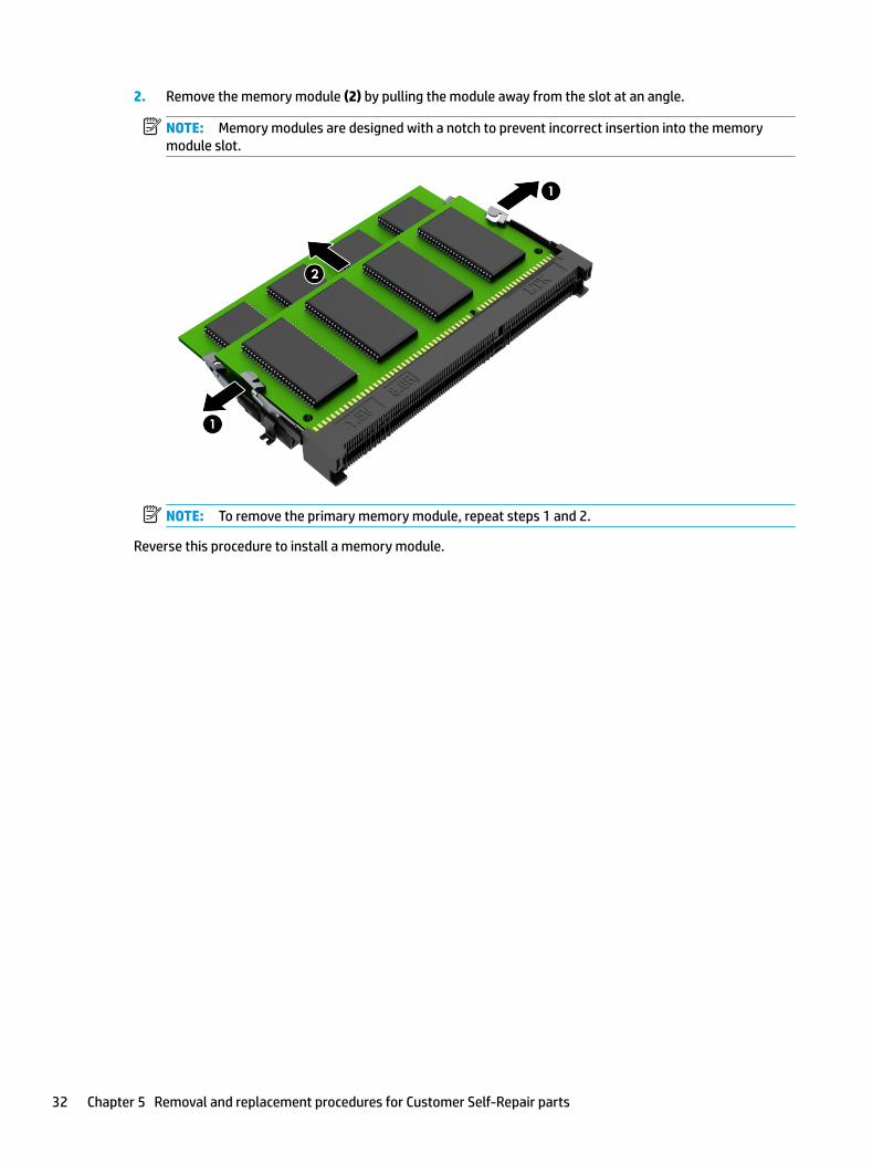
2. Remove the memory module (2) by pulling the module away from the slot at an angle.
NOTE: Memory modules are designed with a notch to prevent incorrect insertion into the memory module slot.
NOTE: To remove the primary memory module, repeat steps 1 and 2.
Reverse this procedure to install a memory module.
32 Chapter 5 Removal and replacement procedures for Customer Self-Repair parts

6 Removal and replacement procedures for authorized service provider parts
CAUTION: Components described in this chapter should be accessed only by an authorized service provider. Accessing these parts can damage the computer or void the warranty.
Component replacement proceduresNOTE: Details about your computer, including model, serial number, product key, and length of warranty, are on the service tag at the bottom of your computer. See Labels on page 15 for details.
NOTE: HP continually improves and changes product parts. For complete and current information on supported parts for your computer, go to http://partsurfer.hp.com, select your country or region, and then follow the on-screen instructions.
There may be as many as 85 screws that must be removed, replaced, and/or loosened when servicing the parts described in this chapter. Make special note of each screw size and location during removal and replacement.
Base enclosure
Description Spare part number
Base enclosure in Twinkle Black 862961-001
Before removing the base enclosure, follow these steps:
1. Turn off the computer. If you are unsure whether the computer is off or in Hibernation, turn the computer on, and then shut it down through the operating system.
2. Disconnect the power from the computer by first unplugging the power cord from the AC outlet and then unplugging the AC adapter from the computer.
3. Disconnect all external devices connected to the computer.
4. Remove the following components:
▲ Service door (see Service door on page 29)
Remove the base enclosure:
1. Remove the two hinge screw covers (1), two back screw covers (2), and two side screw covers (3).
Component replacement procedures 33

2. Remove the four front M2x6.0 screws (1), the five M2x6.0 screws (2), and the two M3.25x6.0 screws (3).
3. Insert a thin plastic tool (1) to separate the base enclosure from the top cover, and then remove the base enclosure (2).
Reverse the removal procedures to install the base enclosure.
34 Chapter 6 Removal and replacement procedures for authorized service provider parts

Battery
Description Spare part number
Battery 6 cell, 95 WH, 4.15 Ah, LI 853294-855
Before removing the battery, follow these steps:
1. Turn off the computer. If you are unsure whether the computer is off or in Hibernation, turn the computer on, and then shut it down through the operating system.
2. Disconnect the power from the computer by first unplugging the power cord from the AC outlet and then unplugging the AC adapter from the computer.
3. Disconnect all external devices from the computer.
4. Remove the following components:
a. Service door (see Service door on page 29)
b. Base enclosure (see Base enclosure on page 33)
Remove the battery:
WARNING! To reduce potential safety issues, use only the user-replaceable battery provided with the computer, a replacement battery provided by HP, or a compatible battery purchased from HP.
CAUTION: Removing a user-replaceable battery that is the sole power source for the computer can cause loss of information. To prevent loss of information, save your work or shut down the computer through Windows before removing the battery.
1. Disconnect the battery cable.
IMPORTANT: Note the cable routing before you remove the cables.
2. Carefully disconnect the right speaker connector (1) from the system board.
Component replacement procedures 35

3. Remove the two Phillips M2x4.0 screws (2) securing the right speaker.
4. Release the speaker cable from the routing channels (3) on the battery.
5. Lift the speaker cable and right speaker (4) to move them away from the battery.
6. Remove the six M2x4.0 screws (1) securing the battery. The battery cable may be moved to access two of the battery screws.
7. Remove the battery from the computer (2).
To insert the battery, reverse the removal procedures.
36 Chapter 6 Removal and replacement procedures for authorized service provider parts

Hard drive
Description Spare part number
Hard drive
● 1 TB 5400 RPM SATA RAW HYBRID 8 GB 731999-005
● 2 TB 5400 RPM SATA RAW 9.5 mm 801808-005
● 1 TB 7200 RPM SATA RAW 9.5 mm 766644-005
Hard drive connector and cable 862964-001
Hard drive brackets with rubber 911227-001
Before removing the hard drive, follow these steps:
1. Turn off the computer. If you are unsure whether the computer is off or in Hibernation, turn the computer on, and then shut it down through the operating system.
2. Disconnect the power from the computer by first unplugging the power cord from the AC outlet and then unplugging the AC adapter from the computer.
3. Disconnect all external devices from the computer.
4. Remove the following components:
a. Service door (see Service door on page 29)
b. Base enclosure (see Base enclosure on page 33)
c. Disconnect the battery (see Battery on page 35)
Remove the hard drive:
NOTE: Use minimal force when lifting the locking bar up on the ZIF connector and disconnecting the cable.
1. Open the zero insertion force (ZIF) connector (1) to release the hard drive cable from the system board.
Component replacement procedures 37

2. Lift the back of the hard drive (2) up, and then remove the drive (3).
3. If it is necessary to disassemble the hard drive, perform the following steps:
a. Remove the hard drive cable connector (1) from the hard drive.
b. Slide the two hard drive brackets (2) off the hard drive.
Reverse this procedure to reassemble and install the hard drive.
38 Chapter 6 Removal and replacement procedures for authorized service provider parts

SSD (M.2)
Description Spare part number
M.2 SATA SSD, PCIe NVMe TLC
● 128 GB 2280 M2 SATA-3 Value PA 827560-026
● 256 GB 2280 M2 PCIe 3x4SS NVMe TLC PA 847109-002
● 512 GB 2280 M2 PCIe 3x4SS NVMe TLC PA 847110-004
Before removing the SSD, follow these steps:
1. Turn off the computer. If you are unsure whether the computer is off or in Hibernation, turn the computer on, and then shut it down through the operating system.
2. Disconnect the power from the computer by first unplugging the power cord from the AC outlet and then unplugging the AC adapter from the computer.
3. Disconnect all external devices from the computer.
4. Remove the following components:
a. Service door (see Service door on page 29)
b. Base enclosure (see Base enclosure on page 33)
c. Disconnect the battery (see Front speakers on page 40)
Remove the SSD:
1. Remove the Phillips M2.0x3 screw (1) that secures the SSD to the system board.
2. Remove the SSD (2) by pulling the drive away from the slot at an angle.
Reverse this procedure to install the SSD.
Component replacement procedures 39

Front speakers
NOTE: The speaker spare part kit includes the cable.
Description Spare part number
Speaker Kit (includes right and left speakers for front and rear) 862958-001
IMPORTANT: Make special note of each screw and screw lock size and location during removal and replacement.
Before removing the speaker, follow these steps:
1. Shut down the computer.
2. Disconnect the power from the computer by first unplugging the power cord from the AC outlet and then unplugging the AC adapter from the computer.
3. Disconnect all external devices connected to the computer.
4. Remove the following components:
a. Service door (see Service door on page 29)
b. Base enclosure (see Base enclosure on page 33)
c. Disconnect the battery (see Battery on page 35)
d. SSD (see SSD (M.2) on page 39)
Remove the front speakers:
1. Carefully disconnect the right speaker connector (1) from the system board.
2. Remove the four Phillips M2x4.0 screws (2) securing the speakers.
3. Release the display cable from the routing channels (3) on the battery.
40 Chapter 6 Removal and replacement procedures for authorized service provider parts
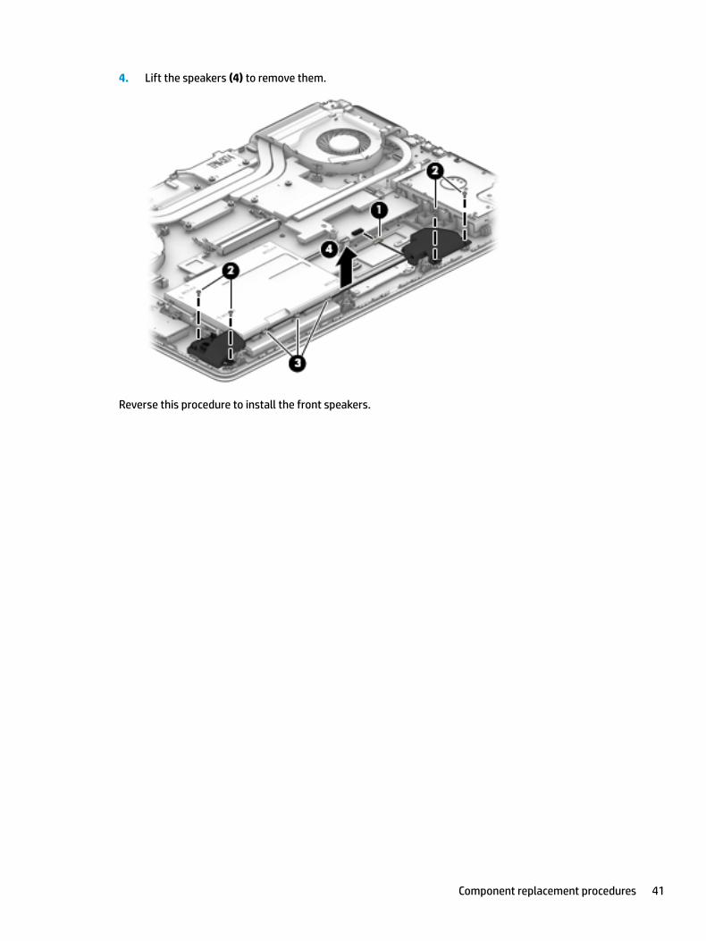
4. Lift the speakers (4) to remove them.
Reverse this procedure to install the front speakers.
Component replacement procedures 41
WLAN module
Description Spare part number
Intel Dual Band Wireless-AC 7265 802.11 ac 2x2 WiFi + Bluetooth 4.2 Combo Adapter (non vPRO) 793840-005
CAUTION: To prevent an unresponsive system, replace the wireless module only with a wireless module authorized for use in the computer by the governmental agency that regulates wireless devices in your country or region. If you replace the module and then receive a warning message, remove the module to restore device functionality, and then contact technical support.
Before removing the WLAN module, follow these steps:
1. Turn off the computer. If you are unsure whether the computer is off or in Hibernation, turn the computer on, and then shut it down through the operating system.
2. Disconnect the power from the computer by first unplugging the power cord from the AC outlet and then unplugging the AC adapter from the computer.
3. Disconnect all external devices from the computer.
4. Remove the following components:
a. Service door (see Service door on page 29)
b. Base enclosure (see Base enclosure on page 33)
c. Disconnect the battery (see Battery on page 35)
Remove the WLAN module:
1. Disconnect the WLAN antenna cables (1) from the terminals on the WLAN module.
NOTE: The WLAN antenna cable labeled “1” connects to the WLAN module “Main” terminal labeled “1”. The WLAN antenna cable labeled “2” connects to the WLAN module “Aux” terminal labeled “2”.
2. Remove the Phillips M2x3.0 screw (2) that secures the WLAN module to the system board. (The WLAN module tilts up.)
42 Chapter 6 Removal and replacement procedures for authorized service provider parts
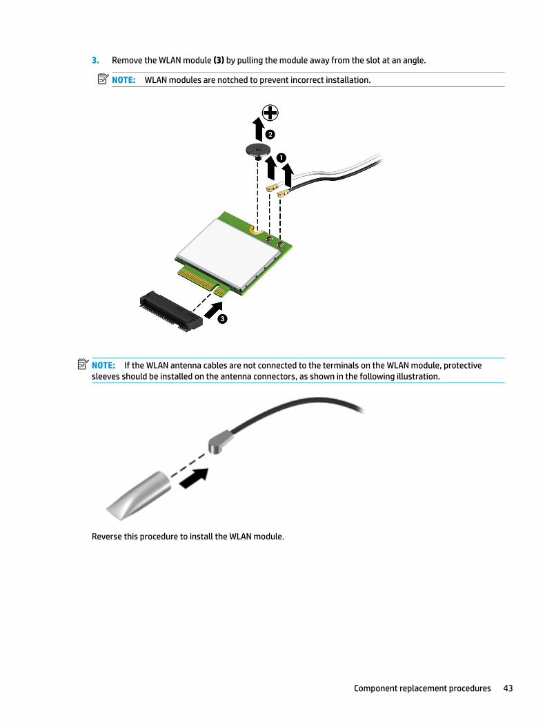
3. Remove the WLAN module (3) by pulling the module away from the slot at an angle.
NOTE: WLAN modules are notched to prevent incorrect installation.
NOTE: If the WLAN antenna cables are not connected to the terminals on the WLAN module, protective sleeves should be installed on the antenna connectors, as shown in the following illustration.
Reverse this procedure to install the WLAN module.
Component replacement procedures 43

Fans
Description Spare part number
Fans (includes left and right fans, plastic thermal cover, and sponge) 910440-001
Before removing the fan, follow these steps:
1. Turn off the computer. If you are unsure whether the computer is off or in Hibernation, turn the computer on, and then shut it down through the operating system.
2. Disconnect the power from the computer by first unplugging the power cord from the AC outlet and then unplugging the AC adapter from the computer.
3. Disconnect all external devices from the computer.
4. Remove the following components:
a. Service door (see Service door on page 29)
b. Base enclosure (see Base enclosure on page 33)
c. Disconnect the battery (see Battery on page 35)
Remove the fans:
1. Disconnect the fan cable (1) from the system board.
2. Remove the six Phillips M2.0 x 4.5 screws (2) that secure the fans to the top cover.
3. Release the plastic thermal cover (3) on the left fan from the system board.
4. Remove each fan (4).
Reverse this procedure to install the fans.
44 Chapter 6 Removal and replacement procedures for authorized service provider parts
Heatsink
Description Spare part number
Heatsink, includes thermal pads, thermal plastic, and spacer sponges 903131-001
Before removing the heatsink, follow these steps:
1. Turn off the computer. If you are unsure whether the computer is off or in Hibernation, turn the computer on, and then shut it down through the operating system.
2. Disconnect the power from the computer by first unplugging the power cord from the AC outlet and then unplugging the AC adapter from the computer.
3. Disconnect all external devices from the computer.
4. Remove the following components:
a. Service door (see Service door on page 29)
b. Base enclosure (see Base enclosure on page 33)
c. Disconnect the battery (see Battery on page 35)
d. Fans (see Fans on page 44)
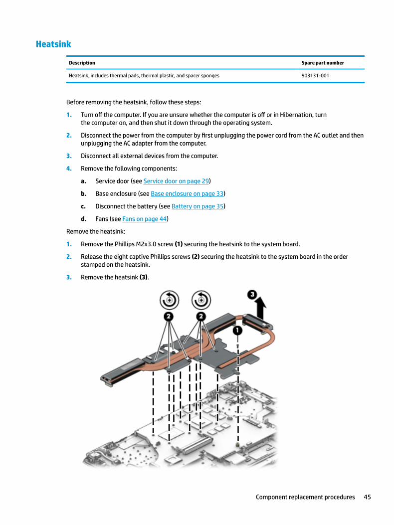
Remove the heatsink:
1. Remove the Phillips M2x3.0 screw (1) securing the heatsink to the system board.
2. Release the eight captive Phillips screws (2) securing the heatsink to the system board in the order stamped on the heatsink.
3. Remove the heatsink (3).
Component replacement procedures 45

4. The following illustration shows the replacement thermal material locations. The thermal material must be thoroughly cleaned from the surfaces of the heat sink and the system board components each time the heat sink is removed. Replacement thermal material is included with the heat sink.
NOTE: If you are replacing the system board, but not the heat sink, remove any thermal pads that remain on the system board and place them on the heat sink. If you are replacing the heatsink, remove any thermal pads that remain on the system board.
Thermal paste is used on the system board components (1), (2) and on the heat sink areas (2), (4) that service them.
Reverse this procedure to install the heatsink.
46 Chapter 6 Removal and replacement procedures for authorized service provider parts
System board
Description Spare part number
System board
NVIDIA N17E-G1 (GeForce GTX 1060), 6 GB, i7-6700HQ 862261-601
NVIDIA N17E-G1 (GeForce GTX 1060), 6 GB, i5-6300HQ 862262-601
NVIDIA N17E-G2 (GeForce GTX 1070), 8 GB, i7-6700HQ 862263-601
IMPORTANT: Make special note of each screw and screw lock size and location during removal and replacement.
Before removing the system board, follow these steps:
1. Shut down the computer.
2. Disconnect the power from the computer by first unplugging the power cord from the AC outlet and then unplugging the AC adapter from the computer.
3. Disconnect all external devices connected to the computer.
4. Remove the following components:
a. Service door (see Service door on page 29)
b. Base enclosure (see Base enclosure on page 33)
c. Battery (see Battery on page 35)
d. Hard drive (see Hard drive on page 37)
e. SSD (see SSD (M.2) on page 39)
f. Front speakers (see Front speakers on page 40)
g. Fans (see Fans on page 44)
h. Heatsink (see Heatsink on page 45)
NOTE: When replacing the system board, be sure that the following components are removed from the defective system board and installed on the replacement system board:
● WLAN module (see WLAN module on page 42)
● Memory modules (see Memory module on page 31)
● RTC battery (see RTC battery on page 51)
● Thermal pads that remained on the system board should be remove and placed on the heatsink (see Heatsink on page 45)
Remove the system board:
1. If they are not already disconnected, disconnect the following cables from the system board (note the routing location of the cables when removing them):
NOTE: Use minimal force when lifting the locking bar up on a ZIF connector and disconnecting the cable.
(1) Power in connection cables
Component replacement procedures 47

(2) Backlight cable
(3) Keyboard cable
(4) Touchpad cable
(5) Display cable
(6) USB board ribbon cable
(7)Speaker cable
2. Remove the two Phillips M2x4.0 screws (1) securing the system board to the computer.
3. Release the system board from the latch (2) securing it to the computer.
48 Chapter 6 Removal and replacement procedures for authorized service provider parts

4. Lift the system board (3), and then remove it.
5. To remove the USB card cable, carefully place the system board face down.
Component replacement procedures 49

6. Open the ZIF connector (1) to release the USB card cable from the system board, and then remove the cable (2).
Reverse this procedure to install the system board.
IMPORTANT: After system board replacement, be sure to complete post-installation tasks as required that may include:
● Verifying functionality of the computer
● Updating the BIOS; see Using Setup Utility (BIOS) on page 71
50 Chapter 6 Removal and replacement procedures for authorized service provider parts

RTC battery
Description Spare part number
RTC battery 857380-001
Before removing the RTC battery, follow these steps:
1. Shut down the computer.
2. Disconnect the power from the computer by first unplugging the power cord from the AC outlet and then unplugging the AC adapter from the computer.
3. Disconnect all external devices connected to the computer.
4. Remove the following components:
a. Service door (see Service door on page 29)
b. Base enclosure (see Base enclosure on page 33)
c. Battery (see Battery on page 35)
d. Hard drive (see Hard drive on page 37)
e. SSD (see SSD (M.2) on page 39)
f. Front speakers (see Front speakers on page 40)
g. Fans (see Fans on page 44)
h. Heatsink (see Heatsink on page 45)
i. System board (see System board on page 47)
Remove the RTC battery:
1. Carefully place the system board face down.
Component replacement procedures 51
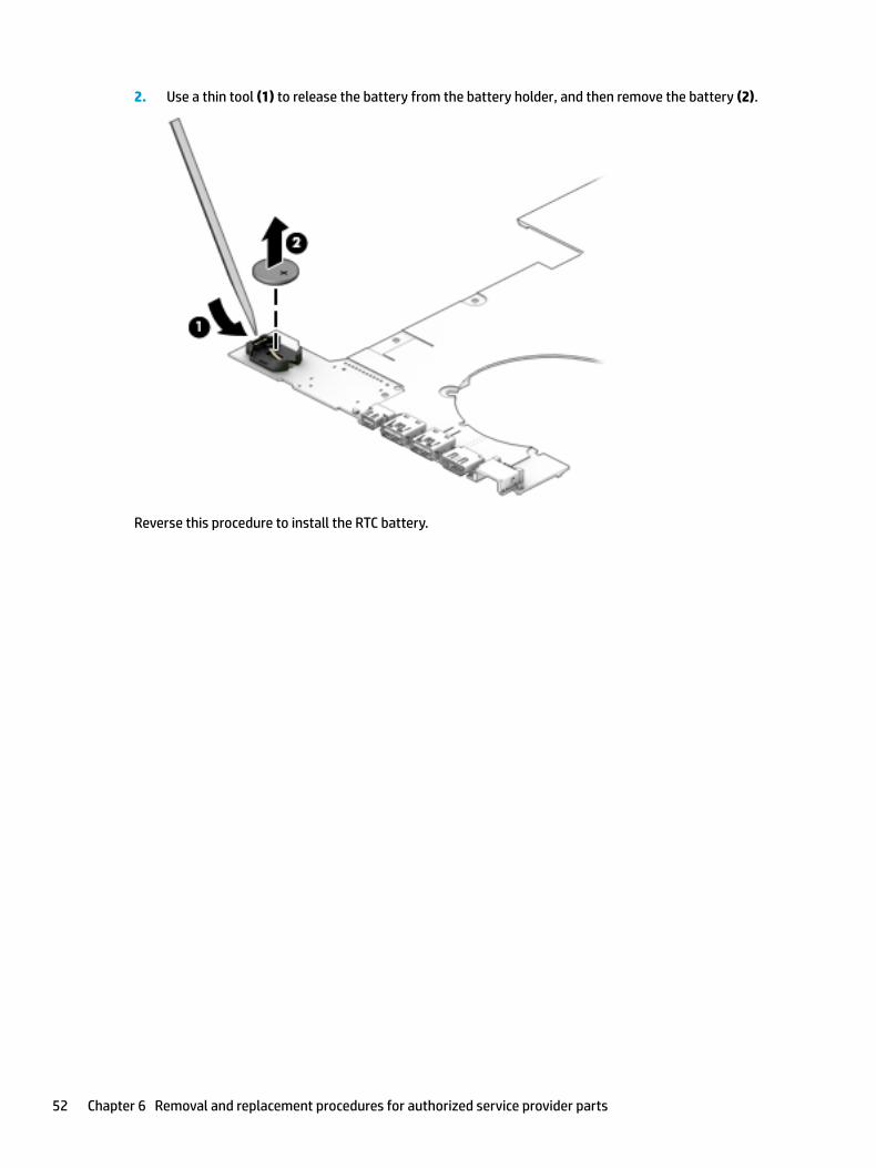
2. Use a thin tool (1) to release the battery from the battery holder, and then remove the battery (2).
Reverse this procedure to install the RTC battery.
52 Chapter 6 Removal and replacement procedures for authorized service provider parts

USB board
Description Spare part number
USB board 862971-001
USB board cable 862967-001
Before removing the USB board, follow these steps:
1. Turn off the computer. If you are unsure whether the computer is off or in Hibernation, turn the computer on, and then shut it down through the operating system.
2. Disconnect the power from the computer by first unplugging the power cord from the AC outlet and then unplugging the AC adapter from the computer.
3. Disconnect all external devices from the computer.
4. Remove the following components:
a. Service door (see Service door on page 29)
b. Base enclosure (see Base enclosure on page 33)
c. Disconnect the battery (see Battery on page 35)
d. Fans (see Fans on page 44)
e. Heatsink (see Heatsink on page 45)
f. Disconnect the USB board cable from the system board (see System board on page 47)
Remove the USB board:
1. Open the ZIF connector (1) to release the power button board cable from the USB board.
CAUTION: Do not use force on the security hook. It is part of the top cover.
2. Carefully disengage the USB board from the security hook (2) that secures the USB board to the top cover.
3. Lift the back side of the USB board (3).
Component replacement procedures 53
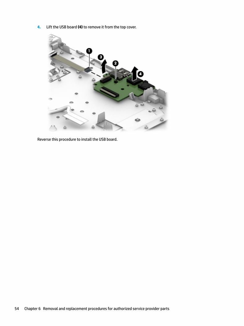
4. Lift the USB board (4) to remove it from the top cover.
Reverse this procedure to install the USB board.
54 Chapter 6 Removal and replacement procedures for authorized service provider parts

Power button board
Description Spare part number
Power button board 862970-001
Power button board cable 862965-001
Before removing the power button board, follow these steps:
1. Turn off the computer. If you are unsure whether the computer is off or in Hibernation, turn the computer on, and then shut it down through the operating system.
2. Disconnect the power from the computer by first unplugging the power cord from the AC outlet and then unplugging the AC adapter from the computer.
3. Disconnect all external devices from the computer.
4. Remove the following components:
a. Service door (see Service door on page 29)
b. Base enclosure (see Base enclosure on page 33)
c. Disconnect the battery (see Battery on page 35)
d. Fans (see Fans on page 44)
e. Heatsink (see Heatsink on page 45)
Remove the power button board:
1. Open the ZIF connector (1) to release the power button board cable from the power button board.
2. Remove the two Phillips M2x4.0 screws (2) securing the power button board to the computer.
3. Remove the power button board (3).
Component replacement procedures 55

Reverse this procedure to install the power button board.
56 Chapter 6 Removal and replacement procedures for authorized service provider parts

Rear speakers
NOTE: The speaker spare part kit includes the cable.
Description Spare part number
Speaker Kit (includes right and left speakers for front and rear) 862958-001
IMPORTANT: Make special note of each screw and screw lock size and location during removal and replacement.
Before removing the speaker, follow these steps:
1. Shut down the computer.
2. Disconnect the power from the computer by first unplugging the power cord from the AC outlet and then unplugging the AC adapter from the computer.
3. Disconnect all external devices connected to the computer.
4. Remove the following components:
a. Service door (see Service door on page 29)
b. Base enclosure (see Base enclosure on page 33)
c. Battery (see Battery on page 35)
d. Hard drive (see Hard drive on page 37)
e. SSD (see SSD (M.2) on page 39)
f. Front speakers (see Front speakers on page 40)
g. Fans (see Fans on page 44)
h. Heatsink (see Heatsink on page 45)
i. System board (see System board on page 47)
Remove the rear speakers:
1. Remove the three Phillips M2x4.0 screws (1) securing the speakers to the top cover.
Component replacement procedures 57

2. Lift the speakers (2) to remove them.
Reverse this procedure to install the rear speakers.
58 Chapter 6 Removal and replacement procedures for authorized service provider parts

TouchPad board
Description Spare part number
TouchPad board 862959-001
TouchPad cable 862966-001
TouchPad rubber click button 910443-001
Before removing the TouchPad board, follow these steps:
1. Turn off the computer. If you are unsure whether the computer is off or in Hibernation, turn the computer on, and then shut it down through the operating system.
2. Disconnect the power from the computer by first unplugging the power cord from the AC outlet and then unplugging the AC adapter from the computer.
3. Disconnect all external devices from the computer.
4. Remove the following components:
a. Service door (see Service door on page 29)
b. Base enclosure (see Base enclosure on page 33)
c. Battery (see Battery on page 35)
d. Hard drive (see Hard drive on page 37)
e. SSD (see SSD (M.2) on page 39)
f. Front speakers (see Front speakers on page 40)
g. Fans (see Fans on page 44)
h. Heatsink (see Heatsink on page 45)
i. System board (see System board on page 47)
Remove the TouchPad board:
1. Carefully remove the three Phillips M2x2.5 screws (1) that secure the TouchPad bracket to the computer.
2. Remove the TouchPad bracket (2) that secures the TouchPad board.
3. If it is necessary to replace the TouchPad rubber click button, lift the rubber button (3) away from the TouchPad.
Component replacement procedures 59
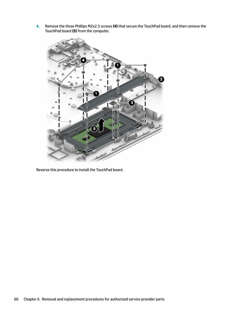
4. Remove the three Phillips M2x2.5 screws (4) that secure the TouchPad board, and then remove the TouchPad board (5) from the computer.
Reverse this procedure to install the TouchPad board.
60 Chapter 6 Removal and replacement procedures for authorized service provider parts

Power in connector
Description Spare part number
Power in connector 907562-001
Before removing the power in connector, follow these steps:
1. Turn off the computer. If you are unsure whether the computer is off or in Hibernation, turn the computer on, and then shut it down through the operating system.
2. Disconnect the power from the computer by first unplugging the power cord from the AC outlet and then unplugging the AC adapter from the computer.
3. Disconnect all external devices from the computer.
4. Remove the following components:
a. Service door (see Service door on page 29)
b. Base enclosure (see Base enclosure on page 33)
c. Battery (see Battery on page 35)
d. Hard drive (see Hard drive on page 37)
e. SSD (see SSD (M.2) on page 39)
f. Front speakers (see Front speakers on page 40)
g. Fans (see Fans on page 44)
h. Heatsink (see Heatsink on page 45)
i. System board (see System board on page 47)
Remove the power in connector:
1. Remove the three Phillips M2.5x3.5 screws (1) securing the left display hinge.
2. Lift the left display hinge (2) holding the power in connector.
Component replacement procedures 61

3. Remove the connector (3).
Reverse this procedure to install the power in connector.
62 Chapter 6 Removal and replacement procedures for authorized service provider parts
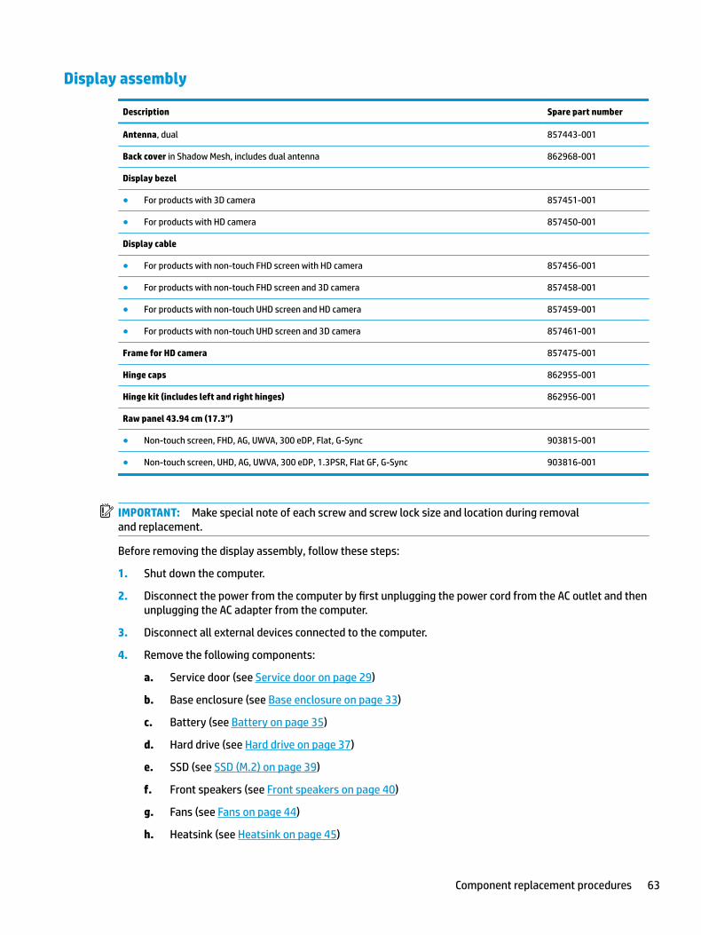
Display assembly
Description Spare part number
Antenna, dual 857443-001
Back cover in Shadow Mesh, includes dual antenna 862968-001
Display bezel
● For products with 3D camera 857451-001
● For products with HD camera 857450-001
Display cable
● For products with non-touch FHD screen with HD camera 857456-001
● For products with non-touch FHD screen and 3D camera 857458-001
● For products with non-touch UHD screen and HD camera 857459-001
● For products with non-touch UHD screen and 3D camera 857461-001
Frame for HD camera 857475-001
Hinge caps 862955-001
Hinge kit (includes left and right hinges) 862956-001
Raw panel 43.94 cm (17.3”)
● Non-touch screen, FHD, AG, UWVA, 300 eDP, Flat, G-Sync 903815-001
● Non-touch screen, UHD, AG, UWVA, 300 eDP, 1.3PSR, Flat GF, G-Sync 903816-001
IMPORTANT: Make special note of each screw and screw lock size and location during removal and replacement.
Before removing the display assembly, follow these steps:
1. Shut down the computer.
2. Disconnect the power from the computer by first unplugging the power cord from the AC outlet and then unplugging the AC adapter from the computer.
3. Disconnect all external devices connected to the computer.
4. Remove the following components:
a. Service door (see Service door on page 29)
b. Base enclosure (see Base enclosure on page 33)
c. Battery (see Battery on page 35)
d. Hard drive (see Hard drive on page 37)
e. SSD (see SSD (M.2) on page 39)
f. Front speakers (see Front speakers on page 40)
g. Fans (see Fans on page 44)
h. Heatsink (see Heatsink on page 45)
Component replacement procedures 63
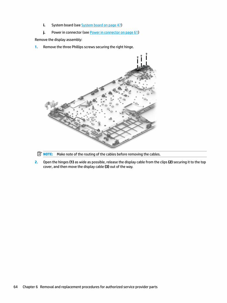
i. System board (see System board on page 47)
j. Power in connector (see Power in connector on page 61)
Remove the display assembly:
1. Remove the three Phillips screws securing the right hinge.
NOTE: Make note of the routing of the cables before removing the cables.
2. Open the hinges (1) as wide as possible, release the display cable from the clips (2) securing it to the top cover, and then move the display cable (3) out of the way.
64 Chapter 6 Removal and replacement procedures for authorized service provider parts
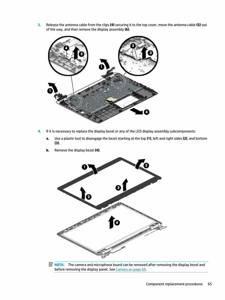
3. Release the antenna cable from the clips (4) securing it to the top cover, move the antenna cable (5) out of the way, and then remove the display assembly (6).
4. If it is necessary to replace the display bezel or any of the LED display assembly subcomponents:
a. Use a plastic tool to disengage the bezel starting at the top (1), left and right sides (2), and bottom (3).
b. Remove the display bezel (4).
NOTE: The camera and microphone board can be removed after removing the display bezel and before removing the display panel. See Camera on page 69.
Component replacement procedures 65

5. If it is necessary to replace the raw display panel, remove the four Phillips M2.0 x 3 screws (1) that secure the display panel to the display enclosure, and then lift the panel (2) to remove it.
6. Remove the tape (1) covering the display panel connector, disconnect the connector (2) from the display panel, and then remove the panel (3).
7. If it is necessary to replace the hinge brackets, remove the three Phillips M2.5x3.0 screws (1) from the bottom of each hinge bracket, and then remove the two Phillips M2x3.0 screws (2) from each bracket.
66 Chapter 6 Removal and replacement procedures for authorized service provider parts

8. Remove the Phillips M2x3.0 screws (3) from the top of each hinge bracket, and then remove the hinge brackets (4).
9. Turn the bracket face down, remove the Phillips M2x3.0 screw (1) from the top, and then remove the hinge bracket cap (2).
10. If it is necessary to replace the WLAN antennas:
a. Release the WLAN antenna cable from the routing path (1) of the display enclosure.
b. Carefully peel back the metallic tape (2) to release the wireless antenna transceivers from the display enclosure.
Component replacement procedures 67

c. Remove the WLAN antenna cable (3) from the display enclosure.
11. If it is necessary to replace the display cable:
a. Release the cable from the routing path (1) along the display enclosure.
b. Remove the cable (2).
IMPORTANT: Use care when handling and installing the new antennas. Accidental bending of the antenna elements will detune the antenna and degrade the computer’s performance.
Reverse this procedure to install the display assembly.
68 Chapter 6 Removal and replacement procedures for authorized service provider parts
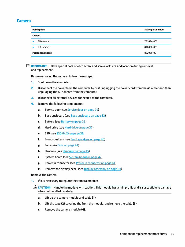
Camera
Description Spare part number
Camera
● 3D camera 781624-005
● HD camera 846006-003
Microphone board 862969-001
IMPORTANT: Make special note of each screw and screw lock size and location during removal and replacement.
Before removing the camera, follow these steps:
1. Shut down the computer.
2. Disconnect the power from the computer by first unplugging the power cord from the AC outlet and then unplugging the AC adapter from the computer.
3. Disconnect all external devices connected to the computer.
4. Remove the following components:
a. Service door (see Service door on page 29)
b. Base enclosure (see Base enclosure on page 33)
c. Battery (see Battery on page 35)
d. Hard drive (see Hard drive on page 37)
e. SSD (see SSD (M.2) on page 39)
f. Front speakers (see Front speakers on page 40)
g. Fans (see Fans on page 44)
h. Heatsink (see Heatsink on page 45)
i. System board (see System board on page 47)
j. Power in connector (see Power in connector on page 61)
k. Remove the display bezel (see Display assembly on page 63)
Remove the camera:
1. If it is necessary to replace the camera module:
CAUTION: Handle the module with caution. This module has a thin profile and is susceptible to damage when not handled carefully.
a. Lift up the camera module and cable (1).
b. Lift the tape (2) covering the from the module, and remove the cable (3).
c. Remove the camera module (4).
Component replacement procedures 69

d. For HD cameras only, lift the frame (5) to remove it from the display enclosure.
2. If it is necessary to replace the microphone module:
CAUTION: Handle the module with caution. This module has a thin profile and is susceptible to damage when not handled carefully.
a. Release the module clips (1) from the module, and detach the cable (2).
b. Detach the camera or microphone module (3) from the display enclosure. (The module is attached to the display enclosure with double-sided adhesive.)
Reverse this procedure to install the camera.
70 Chapter 6 Removal and replacement procedures for authorized service provider parts
7 Using Setup Utility (BIOS)
Setup Utility, or Basic Input/Output System (BIOS), controls communication between all the input and output devices on the system (such as disk drives, display, keyboard, mouse, and printer). Setup Utility (BIOS) includes settings for the types of devices installed, the startup sequence of the computer, and the amount of system and extended memory.
NOTE: To start Setup Utility on convertible computers, your computer must be in notebook mode and you must use the keyboard attached to your notebook.
Starting Setup Utility (BIOS)CAUTION: Use extreme care when making changes in Setup Utility (BIOS). Errors can prevent the computer from operating properly.
▲ Turn on or restart the computer, quickly press esc, and then press f10.
Updating Setup Utility (BIOS)Updated versions of Setup Utility (BIOS) may be available on the HP website.
Most BIOS updates on the HP website are packaged in compressed files called SoftPaqs.
Some download packages contain a file named Readme.txt, which contains information regarding installing and troubleshooting the file.
Determining the BIOS version
To decide whether you need to update Setup Utility (BIOS), first determine the BIOS version on your computer.
To reveal the BIOS version information (also known as ROM date and System BIOS), use one of these options.
● HP Support Assistant
1. Type support in the taskbar search box, and then select the HP Support Assistant app.
– or –
Click the question mark icon in the taskbar.
2. Select My PC, and then select Specifications.
● Setup Utility (BIOS)
1. Start Setup Utility (BIOS) (see Starting Setup Utility (BIOS) on page 71).
2. Select Main, select System Information, and then make note of the BIOS version.
3. Select Exit, select No, and then follow the on-screen instructions.
To check for later BIOS versions, see Downloading a BIOS update on page 72.
Starting Setup Utility (BIOS) 71

Downloading a BIOS update
CAUTION: To reduce the risk of damage to the computer or an unsuccessful installation, download and install a BIOS update only when the computer is connected to reliable external power using the AC adapter. Do not download or install a BIOS update while the computer is running on battery power, docked in an optional docking device, or connected to an optional power source. During the download and installation, follow these instructions:
● Do not disconnect power from the computer by unplugging the power cord from the AC outlet.
● Do not shut down the computer or initiate Sleep.
● Do not insert, remove, connect, or disconnect any device, cable, or cord.
NOTE: If your computer is connected to a network, consult the network administrator before installing any software updates, especially system BIOS updates.
1. Type support in the taskbar search box, and then select the HP Support Assistant app.
– or –
Click the question mark icon in the taskbar.
2. Click Updates, and then click Check for updates and messages.
3. Follow the on-screen instructions.
4. At the download area, follow these steps:
a. Identify the most recent BIOS update and compare it to the BIOS version currently installed on your computer. If the update is more recent than your BIOS version, make a note of the date, name, or other identifier. You may need this information to locate the update later, after it has been downloaded to your hard drive.
b. Follow the on-screen instructions to download your selection to the hard drive.
Make a note of the path to the location on your hard drive where the BIOS update is downloaded. You will need to access this path when you are ready to install the update.
BIOS installation procedures vary. Follow any instructions that appear on the screen after the download is complete. If no instructions appear, follow these steps:
1. Type file in the taskbar search box, and then select File Explorer.
2. Click your hard drive designation. The hard drive designation is typically Local Disk (C:).
3. Using the hard drive path you recorded earlier, open the folder that contains the update.
4. Double-click the file that has an .exe extension (for example, filename.exe).
The BIOS installation begins.
5. Complete the installation by following the on-screen instructions.
NOTE: After a message on the screen reports a successful installation, you can delete the downloaded file from your hard drive.
72 Chapter 7 Using Setup Utility (BIOS)
8 Using HP PC Hardware Diagnostics (UEFI)
HP PC Hardware Diagnostics is a Unified Extensible Firmware Interface (UEFI) that allows you to run diagnostic tests to determine whether the computer hardware is functioning properly. The tool runs outside the operating system so that it can isolate hardware failures from issues that are caused by the operating system or other software components.
When HP PC Hardware Diagnostics (UEFI) detects a failure that requires hardware replacement, a 24-digit Failure ID code is generated. This ID code can then be provided to support to help determine how to correct the problem.
NOTE: To start diagnostics on a convertible computer, your computer must be in notebook mode and you must use the keyboard attached.
To start HP PC Hardware Diagnostics (UEFI), follow these steps:
1. Turn on or restart the computer, and quickly press esc.
2. Press f2.
The BIOS searches three places for the diagnostic tools, in the following order:
a. Connected USB drive
NOTE: To download the HP PC Hardware Diagnostics (UEFI) tool to a USB drive, see Downloading HP PC Hardware Diagnostics (UEFI) to a USB device on page 73.
b. Hard drive
c. BIOS
3. When the diagnostic tool opens, select the type of diagnostic test you want to run, and then follow the on-screen instructions.
NOTE: If you need to stop a diagnostic test, press esc.
Downloading HP PC Hardware Diagnostics (UEFI) to a USB deviceNOTE: The HP PC Hardware Diagnostics (UEFI) download instructions are provided in English only, and you must use a Windows computer to download and create the HP UEFI support environment because only .exe files are offered.
There are two options to download HP PC Hardware Diagnostics to a USB device.
Download the latest UEFI version
1. Go to http://www.hp.com/go/techcenter/pcdiags. The HP PC Diagnostics home page is displayed.
2. In the HP PC Hardware Diagnostics section, select the Download link, and then select Run.
Download any version of UEFI for a specific product
1. Go to http://www.hp.com/support.
2. Select Get software and drivers.
Downloading HP PC Hardware Diagnostics (UEFI) to a USB device 73

3. Enter the product name or number.
– or –
Select Identify now to let HP automatically detect your product.
4. Select your computer, and then select your operating system.
5. In the Diagnostic section, follow the on-screen instructions to select and download the UEFI version you want.
Additional BIOS crisis recovery toolHP provides a BIOS crisis recovery tool through the HP PC Hardware Diagnostics 3-in-1 USB key. This tool can be used by HP authorized service providers to recover systems that have failed due to a corrupted BIOS. For more information about using the 3-in-1 USB key for BIOS crisis recovery, go to http://www.hp.com/go/techcenter/pcdiags. Additional information is included in the web-based training offered by HP University. See the modules that cover HP PC Hardware Diagnostics (UEFI).
74 Chapter 8 Using HP PC Hardware Diagnostics (UEFI)

9 Backing up, restoring, and recovering
This chapter provides information about the following processes. The information in the chapter is standard procedure for most products.
● Creating recovery media and backups
● Restoring and recovering your system
For additional information, refer to the HP support assistant app.
▲ Type support in the taskbar search box, and then select the HP Support Assistant app.
‒ or –
Click the question mark icon in the taskbar.
IMPORTANT: If you will be performing recovery procedures on a tablet, the tablet battery must be at least 70% charged before you start the recovery process.
IMPORTANT: For a tablet with a detachable keyboard, connect the keyboard to the keyboard dock before beginning any recovery process.
Creating recovery media and backupsThe following methods of creating recovery media and backups are available on select products only. Choose the available method according to your computer model.
● Use HP Recovery Manager to create HP Recovery media after you successfully set up the computer. This step creates a backup of the HP Recovery partition on the computer. The backup can be used to reinstall the original operating system in cases where the hard drive is corrupted or has been replaced. For information on creating recovery media, see Creating HP Recovery media (select products only) on page 75. For information on the recovery options that are available using the recovery media, see Using Windows tools on page 76.
● Use Windows tools to create system restore points and create backups of personal information.
For more information, see Recovering using HP Recovery Manager on page 77.
NOTE: If storage is 32 GB or less, Microsoft System Restore is disabled by default.
Creating HP Recovery media (select products only)
If possible, check for the presence of the Recovery partition and the Windows partition. From the Start menu, select File Explorer, and then select This PC.
● If your computer does not list the Windows partition and the Recovery partition, you can obtain recovery media for your system from support. See the Worldwide Telephone Numbers booklet included with the computer. You can also find contact information on the HP website. Go to http://www.hp.com/support, select your country or region, and follow the on-screen instructions.
Creating recovery media and backups 75

You can use Windows tools to create system restore points and create backups of personal information, see Using Windows tools on page 76.
● If your computer does list the Recovery partition and the Windows partition, you can use HP Recovery Manager to create recovery media after you successfully set up the computer. HP Recovery media can be used to perform system recovery if the hard drive becomes corrupted. System recovery reinstalls the original operating system and software programs that were installed at the factory and then configures the settings for the programs. HP Recovery media can also be used to customize the system or restore the factory image if you replace the hard drive.
— Only one set of recovery media can be created. Handle these recovery tools carefully, and keep them in a safe place.
— HP Recovery Manager examines the computer and determines the required storage capacity for the media that will be required.
— To create recovery discs, your computer must have an optical drive with DVD writer capability, and you must use only high-quality blank DVD-R, DVD+R, DVD-R DL, or DVD+R DL discs. Do not use rewritable discs such as CD±RW, DVD±RW, double-layer DVD±RW, or BD-RE (rewritable Blu-ray) discs; they are not compatible with HP Recovery Manager software. Or, instead, you can use a high-quality blank USB flash drive.
— If your computer does not include an integrated optical drive with DVD writer capability, but you would like to create DVD recovery media, you can use an external optical drive (purchased separately) to create recovery discs. If you use an external optical drive, it must be connected directly to a USB port on the computer; the drive cannot be connected to a USB port on an external device, such as a USB hub. If you cannot create DVD media yourself, you can obtain recovery discs for your computer from HP. See the Worldwide Telephone Numbers booklet included with the computer. You can also find contact information on the HP website. Go to http://www.hp.com/support, select your country or region, and follow the on-screen instructions.
— Be sure that the computer is connected to AC power before you begin creating the recovery media.
— The creation process can take an hour or more. Do not interrupt the creation process.
— If necessary, you can exit the program before you have finished creating all of the recovery DVDs. HP Recovery Manager will finish burning the current DVD. The next time you start HP Recovery Manager, you will be prompted to continue.
To create HP Recovery media:
IMPORTANT: For a tablet with a detachable keyboard, connect the keyboard to the keyboard dock before beginning these steps.
1. Type recovery in the taskbar search box, and then select HP Recovery Manager.
2. Select Create recovery media, and then follow the on-screen instructions.
If you ever need to recover the system, see Recovering using HP Recovery Manager on page 77.
Using Windows toolsYou can create recovery media, system restore points, and backups of personal information using Windows tools.
NOTE: If storage is 32 GB or less, Microsoft System Restore is disabled by default.
For more information and steps, see the Get started app.
▲ Select the Start button, and then select the Get started app.
76 Chapter 9 Backing up, restoring, and recovering

Restore and recoveryThere are several options for recovering your system. Choose the method that best matches your situation and level of expertise:
IMPORTANT: Not all methods are available on all products.
● Windows offers several options for restoring from backup, refreshing the computer, and resetting the computer to its original state. For more information see the Get started app.
▲ Select the Start button, and then select the Get started app.
● If you need to correct a problem with a preinstalled application or driver, use the Reinstall drivers and/or applications option (select products only) of HP Recovery Manager to reinstall the individual application or driver.
▲ Type recovery in the taskbar search box, select HP Recovery Manager, select Reinstall drivers and/or applications, and then follow the on-screen instructions.
● If you want to recover the Windows partition to original factory content, you can choose the System Recovery option from the HP Recovery partition (select products only) or use the HP Recovery media. For more information, see Recovering using HP Recovery Manager on page 77. If you have not already created recovery media, see Creating HP Recovery media (select products only) on page 75.
● On select products, if you want to recover the computer's original factory partition and content, or if you have replaced the hard drive, you can use the Factory Reset option of HP Recovery media. For more information, see Recovering using HP Recovery Manager on page 77.
● On select products, if you want to remove the recovery partition to reclaim hard drive space, HP Recovery Manager offers the Remove Recovery Partition option.
For more information, see Removing the HP Recovery partition (select products only) on page 80.
Recovering using HP Recovery Manager
HP Recovery Manager software allows you to recover the computer to its original factory state by using the HP Recovery media that you either created or that you obtained from HP, or by using the HP Recovery partition (select products only). If you have not already created recovery media, see Creating HP Recovery media (select products only) on page 75.
What you need to know before you get started
● HP Recovery Manager recovers only software that was installed at the factory. For software not provided with this computer, you must either download the software from the manufacturer's website or reinstall the software from the media provided by the manufacturer.
IMPORTANT: Recovery through HP Recovery Manager should be used as a final attempt to correct computer issues.
● HP Recovery media must be used if the computer hard drive fails. If you have not already created recovery media, see Creating HP Recovery media (select products only) on page 75.
● To use the Factory Reset option (select products only), you must use HP Recovery media. If you have not already created recovery media, see Creating HP Recovery media (select products only) on page 75.
● If your computer does not allow the creation of HP Recovery media or if the HP Recovery media does not work, you can obtain recovery media for your system from support. See the Worldwide Telephone Numbers booklet included with the computer. You can also find contact information from the HP
Restore and recovery 77
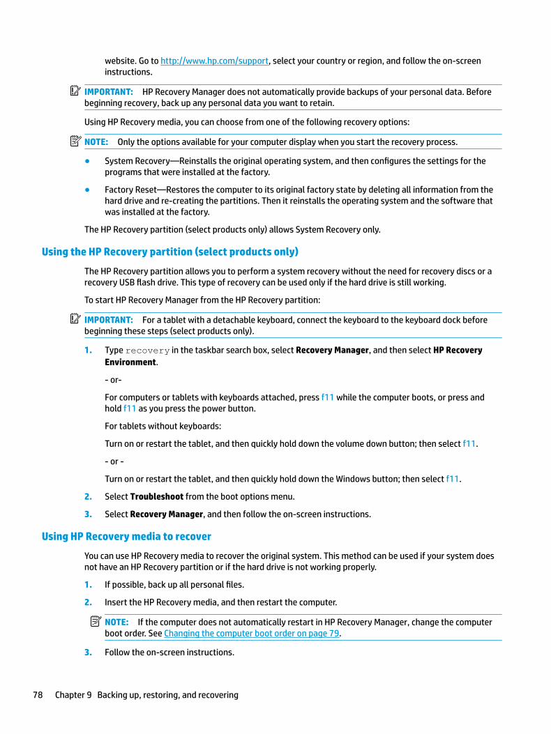
website. Go to http://www.hp.com/support, select your country or region, and follow the on-screen instructions.
IMPORTANT: HP Recovery Manager does not automatically provide backups of your personal data. Before beginning recovery, back up any personal data you want to retain.
Using HP Recovery media, you can choose from one of the following recovery options:
NOTE: Only the options available for your computer display when you start the recovery process.
● System Recovery—Reinstalls the original operating system, and then configures the settings for the programs that were installed at the factory.
● Factory Reset—Restores the computer to its original factory state by deleting all information from the hard drive and re-creating the partitions. Then it reinstalls the operating system and the software that was installed at the factory.
The HP Recovery partition (select products only) allows System Recovery only.
Using the HP Recovery partition (select products only)
The HP Recovery partition allows you to perform a system recovery without the need for recovery discs or a recovery USB flash drive. This type of recovery can be used only if the hard drive is still working.
To start HP Recovery Manager from the HP Recovery partition:
IMPORTANT: For a tablet with a detachable keyboard, connect the keyboard to the keyboard dock before beginning these steps (select products only).
1. Type recovery in the taskbar search box, select Recovery Manager, and then select HP Recovery Environment.
- or-
For computers or tablets with keyboards attached, press f11 while the computer boots, or press and hold f11 as you press the power button.
For tablets without keyboards:
Turn on or restart the tablet, and then quickly hold down the volume down button; then select f11.
- or -
Turn on or restart the tablet, and then quickly hold down the Windows button; then select f11.
2. Select Troubleshoot from the boot options menu.
3. Select Recovery Manager, and then follow the on-screen instructions.
Using HP Recovery media to recover
You can use HP Recovery media to recover the original system. This method can be used if your system does not have an HP Recovery partition or if the hard drive is not working properly.
1. If possible, back up all personal files.
2. Insert the HP Recovery media, and then restart the computer.
NOTE: If the computer does not automatically restart in HP Recovery Manager, change the computer boot order. See Changing the computer boot order on page 79.
3. Follow the on-screen instructions.
78 Chapter 9 Backing up, restoring, and recovering
Changing the computer boot order
If your computer does not restart in HP Recovery Manager, you can change the computer boot order, which is the order of devices listed in BIOS where the computer looks for startup information. You can change the selection to an optical drive or a USB flash drive.
To change the boot order:
IMPORTANT: For a tablet with a detachable keyboard, connect the keyboard to the keyboard dock before beginning these steps.
1. Insert the HP Recovery media.
2. Access BIOS:
For computers or tablets with keyboards attached:
▲ Turn on or restart the computer or tablet, quickly press esc, and then press f9 for boot options.
For tablets without keyboards:
▲ Turn on or restart the tablet, and then quickly hold down the volume down button; then select f9.
- or -
Turn on or restart the tablet, and then quickly hold down the Windows button; then select f9.
3. Select the optical drive or USB flash drive from which you want to boot.
4. Follow the on-screen instructions.
Restore and recovery 79

Removing the HP Recovery partition (select products only)
HP Recovery Manager software allows you to remove the HP Recovery partition to free up hard drive space.
IMPORTANT: After you remove the HP Recovery partition, you will not be able to perform System Recovery or create HP recovery media from the HP Recovery partition. So before you remove the Recovery partition, create HP Recovery media; see Creating HP Recovery media (select products only) on page 75.
NOTE: The Remove Recovery Partition option is only available on products that support this function.
Follow these steps to remove the HP Recovery partition:
1. Type recovery in the taskbar search box, and then select HP Recovery Manager.
2. Select Remove Recovery Partition, and then follow the on-screen instructions.
80 Chapter 9 Backing up, restoring, and recovering

10 Specifications
Computer specifications
Metric U.S.
Dimensions
Width 41.68 cm 16.41 in
Depth 27.95 cm 11.0 in
Height 3.29 cm 1.3 in
Weight 3.35 kg (depending on configuration)
7.39 lbs (depending on configuration)
Input power
Operating voltage and current 19.5 V dc @ 11.8 A – 230 W
Temperature
Operating 5°C to 35°C 41°F to 95°F
Nonoperating ‑20°C to 60°C ‑4°F to 140°F
Relative humidity (noncondensing)
Operating 10% to 90%
Nonoperating 5% to 95%
Maximum altitude (unpressurized)
Operating ‑15 m to 3,048 m ‑50 ft to 10,000 ft
Nonoperating ‑15 m to 12,192 m ‑50 ft to 40,000 ft
NOTE: Applicable product safety standards specify thermal limits for plastic surfaces. The device operates well within this range of temperatures.
Computer specifications 81
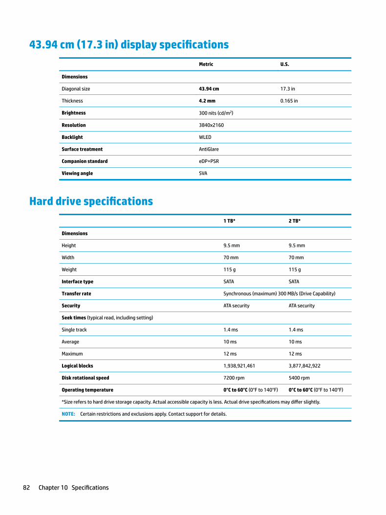
43.94 cm (17.3 in) display specifications
Metric U.S.
Dimensions
Diagonal size 43.94 cm 17.3 in
Thickness 4.2 mm 0.165 in
Brightness 300 nits (cd/m2)
Resolution 3840x2160
Backlight WLED
Surface treatment AntiGlare
Companion standard eDP+PSR
Viewing angle SVA
Hard drive specifications
1 TB* 2 TB*
Dimensions
Height 9.5 mm 9.5 mm
Width 70 mm 70 mm
Weight 115 g 115 g
Interface type SATA SATA
Transfer rate Synchronous (maximum) 300 MB/s (Drive Capability)
Security ATA security ATA security
Seek times (typical read, including setting)
Single track 1.4 ms 1.4 ms
Average 10 ms 10 ms
Maximum 12 ms 12 ms
Logical blocks 1,938,921,461 3,877,842,922
Disk rotational speed 7200 rpm 5400 rpm
Operating temperature 0°C to 60°C (0°F to 140°F) 0°C to 60°C (0°F to 140°F)
*Size refers to hard drive storage capacity. Actual accessible capacity is less. Actual drive specifications may differ slightly.
NOTE: Certain restrictions and exclusions apply. Contact support for details.
82 Chapter 10 Specifications
11 Power cord set requirements
The wide-range input feature of the computer permits it to operate from any line voltage from 100 to 120 V ac, or from 220 to 240 V ac.
The 3-conductor power cord set included with the computer meets the requirements for use in the country or region where the equipment is purchased.
Power cord sets for use in other countries or regions must meet the requirements of the country and region where the computer is used.
Requirements for all countriesThe following requirements are applicable to all countries and regions:
● The length of the power cord set must be at least 1.0 m (3.3 ft) and no more than 2.0 m (6.5 ft).
● All power cord sets must be approved by an acceptable accredited agency responsible for evaluation in the country or region where the power cord set will be used.
● The power cord sets must have a minimum current capacity of 10 A and a nominal voltage rating of 125 or 250 V ac, as required by the power system of each country or region.
● The appliance coupler must meet the mechanical configuration of an EN 60 320/IEC 320 Standard Sheet C13 connector for mating with the appliance inlet on the back of the computer.
Requirements for all countries 83

Requirements for specific countries and regions
Country/region Accredited agency Applicable note number
Argentina IRAM 1
Australia SAA 1
Austria OVE 1
Belgium CEBEC 1
Brazil ABNT 1
Canada CSA 2
Chile IMQ 1
Denmark DEMKO 1
Finland FIMKO 1
France UTE 1
Germany VDE 1
India ISI 1
Israel SII 1
Italy IMQ 1
Japan JIS 3
The Netherlands KEMA 1
New Zealand SANZ 1
Norway NEMKO 1
The People's Republic of China CCC 4
Saudi Arabia SASO 7
Singapore PSB 1
South Africa SABS 1
South Korea KTL 5
Sweden SEMKO 1
Switzerland SEV 1
Taiwan BSMI 6
Thailand TISI 1
The United Kingdom ASTA 1
The United States UL 2
1. The flexible cord must be Type HO5VV-F, 3-conductor, 0.75 mm² conductor size. Power cord set fittings (appliance coupler and wall plug) must bear the certification mark of the agency responsible for evaluation in the country or region where it will be used.
2. The flexible cord must be Type SVT/SJT or equivalent, No. 18 AWG, 3-conductor. The wall plug must be a two-pole grounding type with a NEMA 5-15P (15 A, 125 V ac) or NEMA 6-15P (15 A, 250 V ac) configuration. CSA or C-UL mark. UL file number must be on each element.
84 Chapter 11 Power cord set requirements

Country/region Accredited agency Applicable note number
3. The appliance coupler, flexible cord, and wall plug must bear a “T” mark and registration number in accordance with the Japanese Dentori Law. The flexible cord must be Type VCTF, 3-conductor, 0.75 mm² or 1.25 mm² conductor size. The wall plug must be a two-pole grounding type with a Japanese Industrial Standard C8303 (7 A, 125 V ac) configuration.
4. The flexible cord must be Type RVV, 3-conductor, 0.75 mm² conductor size. Power cord set fittings (appliance coupler and wall plug) must bear the CCC certification mark.
5. The flexible cord must be Type H05VV-F 3-conductor, 0.75 mm² conductor size. KTL logo and individual approval number must be on each element. Corset approval number and logo must be printed on a flag label.
6. The flexible cord must be Type HVCTF 3-conductor, 1.25 mm² conductor size. Power cord set fittings (appliance coupler, cable, and wall plug) must bear the BSMI certification mark.
7. For 127 V ac, the flexible cord must be Type SVT or SJT 3-conductor, 18 AWG, with plug NEMA 5-15P (15 A, 125 V ac), with UL and CSA or C-UL marks. For 240 V ac, the flexible cord must be Type H05VV-F 3-conductor, 0.75 mm² or 1.00 mm2 conductor size, with plug BS 1363/A with BSI or ASTA marks.
Requirements for specific countries and regions 85

12 Recycling
When a non-rechargeable or rechargeable battery has reached the end of its useful life, do not dispose of the battery in general household waste. Follow the local laws and regulations in your area for battery disposal.
HP encourages customers to recycle used electronic hardware, HP original print cartridges, and rechargeable batteries. For more information about recycling programs, see the HP Web site at http://www.hp.com/recycle.
86 Chapter 12 Recycling

Index
Symbols/Numerics3D camera
identifying 73D camera light, identifying 7
AAC adapter and battery 5AC adapter, spare part number 23action keys 12
identifying 12airplane mode key 13antenna, spare part number 63antennas
removal 67, 68antennas, spare part number 22audio, product description 2audio-in (microphone) jack 6audio-out (headphone) jacks 5
Bback cover, spare part number 22,
63backups 75base enclosure
removal 33spare part numbers 20, 33
batteryremoval 35spare part number 20, 35
BIOSdetermining version 71downloading an update 72starting the Setup Utility 71updating 71
Bluetooth label 16boot order
changing 79bottom 16buttons
left TouchPad 9power 10right TouchPad 9
Ccamera
identifying 7removal 69spare part numbers 69
camera framespare part number 22, 63
camera light, identifying 7, 8camera module
removal 69camera, identifying 8camera, spare part number 21, 69caps lock light, identifying 10chipset, product description 1components
bottom 14display 7left side 5rear 15right side 4top 9
computer major components 17computer specifications 81connector, power 5
Ddisplay
specifications 82display assembly
removal 63spare part numbers 63subcomponents 21
display bezelremoval 65spare part numbers 21, 63
display cable, spare part numbers22, 63
display hingesspare part number 22
display panelproduct description 1
drive light 4
Eesc key, identifying 12
Ethernet, product description 2
Ffan
spare part number 20, 44fans
removal 44fn key, identifying 12
Ggraphics, product description 1
Hhard drive
product description 1removal 37spare part numbers 19, 22, 37specifications 82
hard drive bracketremoval 38
hard drive cableremoval 37spare part number 22, 37spare part numbers 19
hard drive connectorremoval 37spare part number 37
HDMI portidentifying 4
HDMI to VGA adapter, spare part number 23
heatsinkremoval 45spare part number 20, 45
hinge capsspare part number 22, 63
hinge kitspare part number 63
HP PC Hardware Diagnostics (UEFI)using 73
HP Recovery Managercorrecting boot problems 79starting 78
Index 87

HP Recovery mediacreating 75recovery 78
HP Recovery partitionrecovery 78removing 80
Iintegrated numeric keypad,
identifying 12internal microphones, identifying 7,
8
Jjacks
audio-in (microphone) 6audio-out (headphone) 5network 4RJ-45 (network) 4
Kkeyboard
product description 3spare part numbers 19
keysaction 12airplane mode 13esc 12fn 12Windows 12
Llabels
Bluetooth 16regulatory 16serial number 15service 15wireless certification 16WLAN 16
lightsAC adapter and battery light 5caps lock 10drive 4mute 10power 10RJ-45 (network) status 4
Mmemory
spare part numbers 20, 31memory card reader, identifying 4
memory card, identifying 4memory module
product description 1removal 31spare part numbers 31
microphoneproduct description 2
microphone boardspare part number 69
microphone board, spare part number 21
microphone moduleremoval 69, 70
mini Dual-Mode DisplayPortidentifying 4
minimized image recovery 78minimized image, creating 77model name 1mute light, identifying 10
Nnetwork jack, identifying 4
Ooperating system, product
description 3optical drive
product description 2original system recovery 77
Ppanel
spare part number 63pointing device, product
description 3ports
HDMI 4mini Dual-Mode DisplayPort 4product description 2USB 3.0 4, 5
power board cablespare part numbers 19
power button boardremoval 55spare part number 55spare part numbers 19
power button, identifying 10power connector, identifying 5power cord
requirements for all countries83
requirements for specific countries and regions 84
set requirements 83spare part numbers 23
power in connectorremoval 61spare part number 19, 61
power lights, identifying 10power requirements, product
description 3processor
product description 1product description
audio 2chipset 1display panel 1Ethernet 2external media cards 2graphics 1hard drive 1keyboard 3memory module 1microphone 2operating system 3optical drive 2pointing device 3ports 2power requirements 3processors 1product name 1security 3serviceability 3video 2wireless 2
product name 1product name and number,
computer 15
Rraw panel
spare part number 21recover
options 77recovery
discs 76, 78HP Recovery Manager 77media 78starting 78supported discs 76system 77
88 Index

USB flash drive 78using HP Recovery media 76
recovery mediacreating 75creating using HP Recovery
Manager 76recovery partition
removing 80regulatory information
regulatory label 16wireless certification labels 16
removal/replacementprocedures 29, 33
RJ-45 (network) jack, identifying 4RJ-45 (network) status lights,
identifying 4RTC battery
removal 51spare part number 19, 51
Sscrew covers
spare part numbers 23screw kit
spare part numbers 23security cable slot, identifying 5security, product description 3serial number 15serial number, computer 15service door
removal 29spare part numbers 29
service door, identifying 14service labels, locating 15serviceability, product description 3slots
memory card reader 4security cable 5
speakerremoval 40, 57spare part numbers 40, 57
speakersidentifying 11spare part numbers 19
specificationscomputer 81display 82hard drive 82
SSDremoval 39
spare part number 39spare part numbers 20, 39
supported discs, recovery 76system board
removal 47spare part numbers 19, 47
system recovery 77system restore point
creating 76system restore point, creating 75
TTouchPad
buttons 9TouchPad board
removal 59spare part number 19, 59
Touchpad board cablespare part numbers 19
TouchPad rubber click buttonspare part number 19
TouchPad zone, identifying 9traveling with the computer 16
UUSB 3.0 port, identifying 4, 5USB board
removal 53spare part number 53spare part numbers 20
USB board cableremoval 47spare part numbers 47
Vvents, identifying 5, 14, 15video, product description 2
WWindows
system restore point 75, 76Windows key, identifying 12Windows tools
using 76wireless certification label 16wireless, product description 2WLAN
spare part number 20WLAN antennas, identifying 7, 8WLAN device 16WLAN label 16
WLAN moduleremoval 42spare part number 42
Index 89