ome0502-08 coverc.qxp:om0502-05 cover
TRANSCRIPT

Operator’s ManualPart No. OME0502-09 Printed in U.S.A.
The first production inboard equipped with catalytic converters.
Ken Cook Co.
5400 Old Millington Road Millington, TN 38053
www.indmar.com
OME0502-08 CoverC.qxp:OM0502-05 Cover.qxd 5/20/08 12:56 PM Page 1

PROPOSITION 65
The engine exhaust from this product contains chemicals known to the State of California to cause cancer, birthdefects or other reproductive harm.
WARNING
Date of Purchase:______________________ Owner Name: _____________________________________________
Address: __________________________________________________ City: ________________________________
State/Province: ___________________________ Zip/Postal Code:____________ Country: ____________________
Engine Serial Number: _____________________________ Transmission Serial Number: _______________________
10-20 Hour ServiceDate:___________ Hours:____________By:_______________________________
Every 50 (25) Hour ServiceDate:___________ Hours:____________By:_______________________________
Date:___________ Hours:____________By:_______________________________
Date:___________ Hours:____________By:_______________________________
Date:___________ Hours:____________By:_______________________________
Date:___________ Hours:____________By:_______________________________
Date:___________ Hours:____________By:_______________________________
Date:___________ Hours:____________By:_______________________________
Date:___________ Hours:____________By:_______________________________
Every 100 Hour ServiceDate:___________ Hours:____________By:_______________________________
Date:___________ Hours:____________By:_______________________________
Date:___________ Hours:____________By:_______________________________
Date:___________ Hours:____________By:_______________________________
Date:___________ Hours:____________By:_______________________________
Date:___________ Hours:____________By:_______________________________
Date:___________ Hours:____________By:_______________________________
Date:___________ Hours:____________By:_______________________________
Date:___________ Hours:____________By:_______________________________
Every 300 Hour/Annual ServiceDate:___________ Hours:____________By:_______________________________
Date:___________ Hours:____________By:_______________________________
Date:___________ Hours:____________By:_______________________________
Date:___________ Hours:____________By:_______________________________
Date:___________ Hours:____________By:_______________________________
Date:___________ Hours:____________By:_______________________________
Every 2 Year ServiceDate:___________ Hours:____________By:_______________________________
Date:___________ Hours:____________By:_______________________________
Date:___________ Hours:____________By:_______________________________
OME0502-08 CoverC.qxp:OM0502-05 Cover.qxd 5/20/08 12:56 PM Page 2

OME0502-08 Body.qxd:OM0502-05 Body.qxd 5/28/08 2:06 PM Page 1

OME0502-08 Body.qxd:OM0502-05 Body.qxd 5/28/08 2:06 PM Page 2

Indmar Marine Engines i
Throughout this manual, specific precautions and sym-bols identify safety related information.
The Safety Alert Symbol means ATTENTION!BECOME ALERT! YOUR SAFETY IS INVOLVED!
Indicates the presence of a hazard which
WILL cause SEVERE injury, death or sub-
stantial property damage.
Indicates the presence of a hazard which
CAN cause SEVERE injury, death or substan-
tial property damage.
Indicates the presence of a hazard which
WILL or CAN cause MINOR or MODERATE
personal injury or property damage.
NOTICE
Indicates installation, operation or maintenance infor-mation which is important but not hazard-related.
The precautions listed in this manual and on the engineor boat are not all-inclusive. If a procedure, method, toolor part is not specifically recommended, you must satisfyyourself that it is safe for you and others, and that theengine or boat will not be damaged or made unsafe as aresult of your decision.
! !
IMPORTANT SAFETY INFORMATION
!
OME0502-08 Body.qxd:OM0502-05 Body.qxd 5/28/08 2:06 PM Page i

ii Indmar Marine Engines
5.7L CarburetedIndmar 5.7L Vortec350 Carb Jet
5.7L Electronic Fuel InjectedIndmar 5.7L MPFIIndmar Assault 325Malibu 5.7L LCRMasterCraft 5.7L RTP-1Indmar 5.7L HO*Indmar Assault 340*Malibu Monsoon*MasterCraft MCX*
6.0L Multi Port Fuel InjectedIndmar LS2*MasterCraft LY6*
6.2L Multi Port Fuel Injected383 Indmar MPI*Malibu 383 Hammerhead*
7.0L EnginesMalibu LS7
7.4 Liter EnginesIndmar 454 Carbureted
8.1L EnginesIndmar 8.1L Vortec MPFIMalibu 8.1L Vortec MPFIMasterCraft 8.1L Vortec MPFI
8.2L EnginesIndmar 502 Carbureted
ENGINES COVERED
The information in this manual applies to the following engine models:
* Engines equipped with ETX-Cat catalytic converters.
OME0502-08 Body.qxd:OM0502-05 Body.qxd 5/28/08 2:06 PM Page ii

Indmar Marine Engines iii
Dear Indmar Marine Engine Owner,
Thank you for selecting a boat powered by an Indmar Marine Engine. Indmar is proud to provide the powerto the best boat companies in the business and we hope that pride shows in the quality of our products. Inthe unlikely event that you have a defect related problem with your boat’s engine / drive train, you canrest assured knowing that it is backed by our industry leading 3-year, factory backed warranty coverage.
This is another exciting year for Indmar and for the marine industry. Indmar has expanded its line ofmarine inboard engines equipped with catalytic converters. Indmar’s ETX/CAT system reduces exhaust emis-sions, including carbon monoxide (CO), to provide a cleaner and safer boating experience for you and yourfamily. ETX/CAT is standard on all 2009 model 5.7L, 383 and 6.0L Premium Electronic Fuel Injected (EFI)engines.
If you have any questions concerning your engine that are not covered in this manual, please feel welcometo contact Indmar Customer Service at (901) 353-9930 or visit our website, www.indmar.com, and submityour question.
Thanks again for choosing an Indmar powered boat. We wish you safe, trouble-free boating.
Sincerely,
Team Indmar
WELCOME
OME0502-08 Body.qxd:OM0502-05 Body.qxd 5/28/08 2:06 PM Page iii

iv Indmar Marine Engines
INDMAR MARINE ENGINES COMPANY MISSION
To produce the world’s finest, most advanced and most dependable gasoline inboard marine engines at the best possible price,
while respecting the needs of our employees, customers, vendors and the precious environment we share.
OME0502-08 Body.qxd:OM0502-05 Body.qxd 5/28/08 2:06 PM Page iv
Indmar Marine Engines v
Introduction . . . . . . . . . . . . . . . . . . . . . . . . . . . . . . . . . . . . . . . . . . . . viiChapter 1: First Time Operation and Break-In . . . . . . . . . . . . . . . 1-1
First Time Operation . . . . . . . . . . . . . . . . . . . . . . . . . . . . . . . . . .1-1Chapter 2: General Operations and Warnings . . . . . . . . . . . . . . . 2-1Chapter 3: Engine Starting Procedures . . . . . . . . . . . . . . . . . . . . . 3-1
How to Start Your Engine . . . . . . . . . . . . . . . . . . . . . . . . . . . . . .3-1If Engine Does Not Start . . . . . . . . . . . . . . . . . . . . . . . . . . . . . .3-3How to Clear the Engine . . . . . . . . . . . . . . . . . . . . . . . . . . . . . .3-3Engine Restart . . . . . . . . . . . . . . . . . . . . . . . . . . . . . . . . . . . . . .3-4
Chapter 4: Normal Operation . . . . . . . . . . . . . . . . . . . . . . . . . . . . . 4-1Daily Routine . . . . . . . . . . . . . . . . . . . . . . . . . . . . . . . . . . . . . . . .4-1Operating the Controls . . . . . . . . . . . . . . . . . . . . . . . . . . . . . . . .4-2Unusual Vibration . . . . . . . . . . . . . . . . . . . . . . . . . . . . . . . . . . . .4-3Fuel System . . . . . . . . . . . . . . . . . . . . . . . . . . . . . . . . . . . . . . . .4-4Battery . . . . . . . . . . . . . . . . . . . . . . . . . . . . . . . . . . . . . . . . . . . . .4-4“Service Required” or “Check Engine” Indicator
(EFI Engines Only) . . . . . . . . . . . . . . . . . . . . . . . . . . . . . . . . .4-5Check Transmission Light . . . . . . . . . . . . . . . . . . . . . . . . . . . . .4-6Engine Cooling . . . . . . . . . . . . . . . . . . . . . . . . . . . . . . . . . . . . . .4-6Exhaust Hoses . . . . . . . . . . . . . . . . . . . . . . . . . . . . . . . . . . . . . .4-7Selecting a Propeller . . . . . . . . . . . . . . . . . . . . . . . . . . . . . . . . .4-8
TABLE OF CONTENTS
OME0502-08 Body.qxd:OM0502-05 Body.qxd 5/28/08 2:06 PM Page v

vi Indmar Marine Engines
Chapter 5: Fuel . . . . . . . . . . . . . . . . . . . . . . . . . . . . . . . . . . . . . . . . 5-1What Type of Gasoline to Use . . . . . . . . . . . . . . . . . . . . . . . . . .5-1Using Oxygenated Fuels or Fuels with Alcohol . . . . . . . . . . . .5-2Fuels in Other Countries . . . . . . . . . . . . . . . . . . . . . . . . . . . . . .5-3
Chapter 6: Maintenance . . . . . . . . . . . . . . . . . . . . . . . . . . . . . . . . . 6-1General Service Notes . . . . . . . . . . . . . . . . . . . . . . . . . . . . . . . .6-1Engine Oil . . . . . . . . . . . . . . . . . . . . . . . . . . . . . . . . . . . . . . . . . .6-4Engine Flame Arrestor . . . . . . . . . . . . . . . . . . . . . . . . . . . . . . . .6-9Engine Cooling . . . . . . . . . . . . . . . . . . . . . . . . . . . . . . . . . . . . . .6-9Internal (Cooling System) Care . . . . . . . . . . . . . . . . . . . . . . . .6-12Ignition Timing . . . . . . . . . . . . . . . . . . . . . . . . . . . . . . . . . . . . . .6-15Fuel System . . . . . . . . . . . . . . . . . . . . . . . . . . . . . . . . . . . . . . .6-15Carburetor Adjustments . . . . . . . . . . . . . . . . . . . . . . . . . . . . . .6-16Transmission . . . . . . . . . . . . . . . . . . . . . . . . . . . . . . . . . . . . . . .6-16Electrical System . . . . . . . . . . . . . . . . . . . . . . . . . . . . . . . . . . .6-19Wiring . . . . . . . . . . . . . . . . . . . . . . . . . . . . . . . . . . . . . . . . . . . .6-20
Chapter 7: Storage and Winter Lay-up . . . . . . . . . . . . . . . . . . . . . 7-1General Preparation . . . . . . . . . . . . . . . . . . . . . . . . . . . . . . . . . .7-2Reactivating Engine After Extended Storage . . . . . . . . . . . . . .7-8
Chapter 8: Troubleshooting . . . . . . . . . . . . . . . . . . . . . . . . . . . . . . 8-1Appendix A – Maintenance Components and Fluids . . . . . . . . . .A-1Appendix B – Engine Specifications . . . . . . . . . . . . . . . . . . . . . . . B-1Appendix C – Limited Warranty . . . . . . . . . . . . . . . . . . . . . . . . . . C-1
OME0502-08 Body.qxd:OM0502-05 Body.qxd 5/28/08 2:06 PM Page vi

This manual will acquaint you with basic informationneeded to safely operate and maintain your Indmarengine. We suggest you and all other operators read theentire manual before using your boat.
We recommend you contact your Indmar dealer for allengine service. Certified Indmar Technicians are trained.They have current specifications, parts and the specialequipment needed to service your Indmar engine anddrive line. To find your nearest Indmar dealer, please call(901) 353-9930 or visit our website at www.indmar.com.
To ensure that the proper information is available, notethe six digit engine serial number. Your dealer shouldhave written the engine serial number on the inside backcover of this manual. The serial number is stamped onthe engine block; see the diagram below for locations.The serial number also appears on several stick-on tagsthat are attached to major engine components.
Figure 1.1 – Serial Number Locations
INDM-A001
INTRODUCTION
Indmar Marine Engines vii
OME0502-08 Body.qxd:OM0502-05 Body.qxd 5/28/08 2:06 PM Page vii

viii Indmar Marine Engines
Complete your warranty registration today!
The Federal Boat Safety Act of 1971 requires registra-tions of marine products sold in the United States bemaintained by the manufacturer and dealers of thoseproducts. Your dealer should have completed your warranty registration to comply with federal regulations.This registration enables us to contact you, if it shouldbecome necessary, to change or improve your product.The engine serial number is stamped into the block and should also be written on the inside of the backcover of this manual. Always retain a copy of the serialnumber for your personal records. You can check to see if your engine has been registered by logging ontowww.indmar.us and selecting Engine Registration. Youwill be prompted to enter your six digit engine serialnumber and click on SUBMIT. If your engine has alreadybeen registered, a message will come back informingyou of that. If your engine has not been registered, simply fill out the form with the information requested and press SUBMIT when finished.
Warranty registration must be received within 10 daysafter date of purchase by the first owner. If your engine isnot registered, all warranties may be void.
Make sure your engine is registered!
Upon receipt of the engine registration at Indmar, you willreceive a confirmation letter along with a small gift as atoken of our appreciation. If you have not received yourconfirmation letter and gift within 30 days of purchasingyour boat, contact Indmar Customer Service by phone at901-353-9930 or submit a message on our website,www.indmar.com. Make sure to have your engine serialnumber handy and if you e-mail the information, includeyour name, address, and telephone number.
OME0502-08 Body.qxd:OM0502-05 Body.qxd 5/28/08 2:06 PM Page viii

Indmar Marine Engines ix
Warranty Registration Transfer
The remainder of the engine warranty is transferable to asecond or subsequent owner. Warranty transfers mustbe completed within 10 days of the transfer of owner-ship.
If the trade-in and resale is handled by an authorizedIndmar dealer, the dealer must fill out the warranty regis-tration transfer form and send it and other paperworkspecified along with the warranty transfer fee (currently$200.00) and the transfer will be processed on approvalby Indmar.
If the sale of the boat is from a private owner to anotherindividual, the engine package must be inspected, at theseller or purchaser’s expense, and the Inspection Form,Warranty Transfer Form, specified paperwork and trans-fer fee (currently $200.00) and the transfer will beprocessed on approval by Indmar.
The new boat owner will be notified within 10 days ofIndmar’s receipt of the transfer paperwork whether thetransfer has been accepted or not. If the transfer hasbeen accepted, the warranty expiration date will also beprovided for the new owner.
To obtain enjoyment from your boat, follow recommenda-tions described in this manual. The knowledge you gainthrough careful review will help you experience lastingsatisfaction.
Further information regarding the care, operation,required equipment or specifications for your boat can beobtained from your local US Coast Guard Auxiliary, USPower Squadron, state boating authorities, or theAmerican Red Cross. Know the law and your responsi-bilities as a boat owner.
Any alteration, change, improper maintenance or abnor-mal use by you which renders the engine or any of itscomponents unreasonably dangerous will void all war-ranties and Indmar will not be liable for the resultingdamages or injuries.
OME0502-08 Body.qxd:OM0502-05 Body.qxd 5/28/08 2:06 PM Page ix

x Indmar Marine Engines
EMISSION CONTROL WARRANTY INFORMATION
The inboard engine in your boat includes the IndmarEmission Control Systemidentified as MFI or TBI orEM. Refer to the identifica-tion sticker on your engineto determine which emis-sion control system per-tains to your engine. Thefuel and ignition systemson your engine meet thestringent requirements setforth by the California AirResources Board (CARB).Indmar also uses Sierrabrand anti-freeze in theclosed cooling system ofyour engine to reduce theenvironmental impact inthe event that anti-freeze isexpelled from the engine.
Your Indmar manufactured engine has a special environ-mental label required by the California Air ResourcesBoard (CARB). The label has 1, 2, 3 or 4 stars. A hang-tag, provided with your inboard engine, describes themeaning of the star system.
Operating Fuels and Lubricants
In order to keep your engine operating efficiently and tomaintain the Emission Control System the followingrequirements must be observed.
Fuel – Your engine was designed and certified tooperate on the unleaded fuels listed below. Fuel rat-ings must be based on the (R+M)/2 method and meetthe specifications ASTM D4814 in the US. Thesefuels need no additives for proper operation.
• Malibu Anniversary LS7 and Indmar LS2 engines 91 Octane
• All other Indmar, Malibu orMasterCraft Engines 89 Octane
INDM-A041
INDM-A042
OME0502-08 Body.qxd:OM0502-05 Body.qxd 5/28/08 2:06 PM Page x

Indmar Marine Engines xi
Lubricant – Indmar uses and recommendsPennzoil 15W40 Marine Oil for use in all of itsengines except for the 8.1 liter models which usePennzoil 40W oil. If Pennzoil Marine oil is not available, any appropriate viscosity motor oil meeting the API ratings of SL/SJ, CI-4, CH-4, CG-4 is acceptable. See Chapter 6, Maintenance,for information regarding the use of synthetic oil.
Additives – The only additive that is recommended byIndmar for use in your engine is Sta-Bil brand fuel sta-bilizer. This additive helps preserve the fuel in yourtank and in the engine’s fuel system. We recommendthe use of Sta-Bil during off-season storage and for theboater that consumes less than a full tank of fuel everytwo weeks. See Chapter 5, Fuel, for more information.
Emissions Components Warranty
The following components are considered as part of theemissions control system and are covered under theEmissions Control Warranty.
1. Fuel Metering SystemA. Fuel injectorsB. Fuel pressure regulatorC. Manifold Absolute Pressure SensorD. Throttle Position SensorE. Idle Air Control ValveF. Throttle Body – Port Fuel Injection Models
G. Throttle Body Assembly – Throttle Body Fuel Injection Models
H. CarburetorI. Coolant Temperature SensorJ. Intake ValvesK. Oxygen Sensors
2. Air Induction SystemA. Intake ManifoldB. Air Filter (Flame Arrestor)
3. Ignition SystemA. Spark PlugsB. Electronic Ignition SystemC. Ignition coil and/or control moduleD. Ignition Wires
4. Lubrication SystemA. Oil pump and internal parts
5. Positive Crankcase Ventilation (PCV) SystemA. PCV valveB. Oil Filler Cap
6. Exhaust SystemA. Exhaust manifold(s)B. Exhaust riser(s)C. Exhaust valvesD. Catalytic Converters
7. Miscellaneous Items Used on Above SystemsA. Hoses, clamps, fittings, tubing, sealing gaskets or
devices and mounting hardwareB. Electronic ControlsC. Electronic Control ModuleD. Pulleys, belts and idlers
OME0502-08 Body.qxd:OM0502-05 Body.qxd 5/28/08 2:06 PM Page xi
xii Indmar Marine Engines
NOTICE
The repair or replacement of any warranted part oth-erwise eligible for warranty coverage under theEmission Control Warranty may be excluded fromsuch warranty coverage if Indmar demonstrates thatthe engine has been abused, neglected, or improperlymaintained and that such abuse neglect or impropermaintenance was the direct cause of the need forrepair or replacement of the part.
The emission warranty covers damage to other enginecomponents that is caused by the failure of a warrantedpart.
The Indmar Operator’s Manual provided contains writteninstructions for the proper maintenance and use of yourinboard engine. All emission warranty parts are warrant-ed by Indmar for the entire warranty period of the engine,unless the part is scheduled for replacement as requiredmaintenance in the Operator’s Manual.
Emission warranty parts that are scheduled for replace-ment, as required maintenance, are warranted by Indmarfor the period of time before the first scheduled replace-ment date for that part. Emission warranted parts thatare scheduled for regular inspection, but not regularreplacement, are warranted by Indmar for the entire warranty period of the inboard engine.
Any emission warranty part repaired or replaced underthe terms of this warranty statement is warranted byIndmar for the remainder of the warranty period of theoriginal part. All parts replaced under this limited warrantybecome the property of Indmar.
If the ownership of a product is transferred duringEmission Components Warranty period, this warrantyshall also be transferred and be valid for the remainingcoverage period provided that Indmar is notified in thefollowing way:
a. The former owner contacts Indmar and provides uswith the required information listed below; or
b. Indmar receives a proof that the former owner agreedto the transfer of ownership and we are provided withthe information listed below.
- Current owner’s name, address, telephone, engine serial number and date of purchase
- New owner’s name, address, telephone, engine serial number and date of transfer
Send the above information to:
Indmar Products5400 Old Millington RdMillington, TN 38053Attn: Emission Warranty Transfer
OME0502-08 Body.qxd:OM0502-05 Body.qxd 5/28/08 2:06 PM Page xii

Indmar Marine Engines xiii
NOTICE
The above procedure is valid for the transfer of theEmission Components warranty only. Refer to theLimited Warranty in Section C of this manual for informa-tion regarding warranty transfer of the remaining enginecomponents.
Emission Maintenance Requirements
The following component maintenance is required tomaintain the Emission Control System of your engine.See Chapter 6, Maintenance, for procedures.
• Engine oil and filter: Change oil and filter after the first10 hours then every 50 hours or annually, whicheveroccurs first.
• Flame Arrestor: Clean every 100 hours. Replace asnecessary.
• Spark Plugs: Replace every 300 hours or annually,whichever occurs first.
• PCV Valve: Replace every 300 hours or annually,whichever occurs first.
• Spark Plug Wires: Inspect annually. Replace as nec-essary.
NOTICE
Ignition timing, engine idle speed and air-fuel mixtureare not adjustable on this engine. NO OTHERADJUSTMENTS NEEDED.
Emission Maintenance Procedures
Engine Oil and Filter: See Chapter 6, MaintenanceSpark Plugs: See Chapter 6, MaintenancePCV Valve: See Chapter 6, MaintenanceFlame Arrestor: See Chapter 6, MaintenanceSpark Plug Wires: See Chapter 6, MaintenanceBreather Hose: See Chapter 6, MaintenanceIgnition Timing: See Chapter 6, MaintenanceCarburetor Adjustment: See Chapter 6, Maintenance
OME0502-08 Body.qxd:OM0502-05 Body.qxd 5/28/08 2:06 PM Page xiii
xiv Indmar Marine Engines
Engine ModelEngine
OilOil Filter
SparkPlugs
PCVValve
OxygenSensor
FlameArrestor
PlugWires
DistCap
DistRotor
Indmar 5.7L Vortec*
87100115W40
Pennzoil501001
556262 505001
N/A
525006 556083 556084Indmar Assault 310*Indmar 5.7L MPFI*
556199
506002521119
556345 556346
Indmar Assault 325*Malibu 5.7L LCR*
505001751104
MasterCraft 5.7L RTP-1*756004Indmar 5.7L HO
506002
556162
525022Indmar 5.7L Assault 340Malibu Monsoon
505001751104
Malibu 383 HammerheadMasterCraft MCX 525011 756004MasterCraft 6.0L LY6
556188
556134 525021 751202 N/A N/AIndmar 6.0L LS2
Malibu LS78710035W30
Mobil 1556234
N/A
Indmar 454 Carbureted*985139
40WPennzoil
501000 556090 505001 525006 756001 556083 556084Indmar 8.1L Vortec 501001
556198 N/A 525011 756003 N/A N/AMalibu 8.1L Vortec 501015MasterCraft 8.1L Vortec 501015Indmar 502 Carbureted* 501000 556090 505001 525006 756001 556084 556084
*Not for sale in California
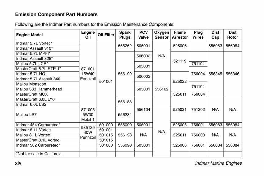
Emission Component Part Numbers
Following are the Indmar Part numbers for the Emission Maintenance Components:
OME0502-08 Body.qxd:OM0502-05 Body.qxd 5/28/08 2:06 PM Page xiv

Indmar Marine Engines xv
CALIFORNIA EMISSION CONTROL
WARRANTY STATEMENT
YOUR WARRANTY RIGHTS AND OBLIGATIONS
The California Air Resources Board and Indmar Productsare pleased to explain the emission control system war-ranty on your 2009 inboard engine. In California, newinboard, engines must be designed, built and equippedto meet the State’s stringent anti-smog standards.Indmar Products must warrant the emission control system in your inboard engine for the time listedbelow provided there has been no abuse, neglect orimproper maintenance of your inboard engine.
Your emission control system may include parts such asthe carburetor or fuel injection system, the ignition system, and catalytic converter. Also included may behoses, belts, connectors and other emission-relatedassemblies.
Where a warrantable condition exists, Indmar Productswill repair your inboard engine at no cost to you, includ-ing diagnosis, parts and labor.
Manufacturer’s Warranty Coverage
Select emission control parts from model year 2003-2009 inboard engines are warranted for 2 years.
Select emission control parts from model year 2009 andlater are warranted for 3 years.
However, warranty coverage based on the hourly periodis only permitted for outboard engines and personalwatercraft equipped with appropriate hour meters or theirequivalent. If any emission-related part on your engine isdefective under warranty, parts will be repaired orreplaced by Indmar Products.
OME0502-08 Body.qxd:OM0502-05 Body.qxd 5/28/08 2:06 PM Page xv

xvi Indmar Marine Engines
Owner’s Warranty Responsibilities
As the inboard engine owner, you are responsible for theperformance of the required maintenance listed in yourowner’s manual. Indmar Products recommends that youretain all receipts covering maintenance on your inboardengine, but Indmar Products cannot deny warranty solelyfor the lack of receipts or your failure to ensure the per-formance of all scheduled maintenance.
As the inboard engine owner, you should be aware thatIndmar Products may deny you warranty coverage ifyour inboard engine or part has failed due to abuse, neg-lect, improper maintenance or unapproved modifications.
If your engine is operated in salt or brackish water, spe-cial precautions, such as flushing the engine internallyand externally, are important. See the “Salt WaterOperation” information in Chapter 6.
You are responsible for presenting your inboard engineto an Indmar Products distribution center as soon as a problem exists. The warranty repairs should be completed in a reasonable amount of time, generallywithin 30 days.
If you have any questions regarding your warranty rightsand responsibilities, you should contact the IndmarDirector of Customer Service at 1-901-353-9930.
OME0502-08 Body.qxd:OM0502-05 Body.qxd 5/28/08 2:06 PM Page xvi

Indmar Marine Engines 1-1
A new engine may use a more than normal
amount of engine oil before it is broken in.
Check your oil level hourly during the break-
in period. Once the engine is broken in,
check the oil level before each day’s use and
more often during sustained periods of high
RPM operation. Some oil use during opera-
tion is normal.
The following checks assumes your dealer has per-formed the pre-delivery service and inspection. Completethe following pre-start check list before starting your enginefor the first time. If you have questions about any of theseprocedures, see your Indmar dealer for assistance.
FIRST TIME OPERATION
1. Check the boat hull and/or garboard drain plug. Makesure they are installed and secure. Check the boatowner’s manual for additional pre-operation checks.
2. Make sure all engine drain plugs are installed. Referto Chapter 7, Storage and Winter Layup. There areseveral drain locations: Block – There are block drain points on both sides ofthe engine. Some engines have brass drain plugs oneach side and some engines have knock sensorsinstalled in the block drain holes (Figure 1.2).
NOTICEOn the 8.1 Liter engine, removing the knock sensordoes NOT drain the block. Remove the plugs from thebrass fillings on both sides of the engine to drainwater from the block.
Exhaust – The drain hose must be connected. Transmission – The transmission oil cooler has onedrain plug. In addition, the Walters V-Drive and ZFSki-Vee (if equipped) have two drain plugs. SeeChapter 7 for instructions.
Chapter 1 FIRST TIME OPERATION AND BREAK-IN
OME0502-08 Body.qxd:OM0502-05 Body.qxd 5/28/08 2:06 PM Page 1-1

1-2 Indmar Marine Engines
Fresh Water Cooling System – If equipped, the heatexchanger has four drain plugs; two for raw water andtwo for coolant. Refer to Chapter 7, Storage andWinter Lay-up.
Figure 1.2 – Anti Knock Sensor
3. Make sure your battery is fully charged and the cablesare clean and tight.
4. Check engine oil for correct level. Refer to Chapter 6,Maintenance.
Figure 1.3 – Engine Dipstick Level
5. Check transmission oil level for correct level. Refer toChapter 6, Maintenance.
6. If your engine is equipped with fresh water cooling,check the expansion tank for the correct level. Referto Chapter 6, Maintenance.
Do not mix antifreeze types.
7. Inspect engine mounts to make sure they aligned andtight. Make sure that the propeller shaft coupler boltsare tight.
Make sure the engine water intake is not
blocked by the trailer bunk. Blocked or
restricted water flow may damage the engine.
IND-A005A
1
ADDOPERATING RANGE SEE OWNERS MANUA
INDM-A003
OME0502-08 Body.qxd:OM0502-05 Body.qxd 5/28/08 2:06 PM Page 1-2

Indmar Marine Engines 1-3
8. Back trailer into the water. Make sure the enginewater intake is submerged.
Before starting engine operate bilge blower
at least 4 minutes and raise engine cover to
ventilate fumes. Inspect engine and compart-
ment for any fluid or fuel leaks. Failure to do
so can possibly result in fire and/or explo-
sion resulting in death or serious injury to
you and your passengers.
Figure 1.4 – Raised Engine Cover
NOTICE
Priming the EFI FuelSystem is requiredbefore starting your
EFI engine for the first time.This allows the electric fuelpump to fill the fuel injectionlines with gasoline. Eachtime you advance the ignitionswitch to the “ON” position,the fuel pump cycles for 2seconds.
NOTICE
Priming fuel systemis not necessary withcarbureted engines.
9. EFI Engines Only. Prime the fuel system by cyclingthe fuel pump eight to ten times before the engine isstarted for the first time. To prime:• Turn the ignition key ON for 5 seconds.• Turn the ignition key OFF for 5 seconds.• Repeat above eight to ten times
! !
ON
STARTOFF
ACC
INDM-A006
Figure 1.5 – Engine“On” Switch
OME0502-08 Body.qxd:OM0502-05 Body.qxd 5/28/08 2:06 PM Page 1-3

1-4 Indmar Marine Engines
NOTICE
The above procedure is only necessary forthe first time the engine is started or in theevent the fuel tank is run dry. If your dealer
prepares your boat for initial delivery, they will performthis procedure for you.
10. Start the engine (Refer to Chapter 2, GeneralOperation and Warnings) and allow it to reach nor-mal operating temperature; keep a close eye on thegauges. If any of the gauges indicate an engineproblem, stop the engine immediately and bring theboat to your Indmar dealer for assistance.
Do not operate starter motor for more than
15 seconds without a 2 (two) minute cool-
down period. Excessively long cranking
times will permanently damage the starter
motor and drain the battery.
Break-In Taking care now to break-in your new Indmar engine isVERY important. When properly broken in, your enginewill last longer, run better and require fewer repairs overits lifetime. Your new Indmar engine does not require anelaborate break-in procedure, just a little care and com-mon sense for the first 10 hours.
Break-in Tips• Always let engine warm up to normal operating tem-
perature before accelerating. • Avoid fast accelerations and don’t carry (or pull) a
heavy load during this period.• Check engine and transmission fluid levels frequently.
During the first 50 to 100 hours, an engine can usemore oil than usual. Maintain oil at proper levels at alltimes but do not overfill.
• Vary your boat speed during break-in. Do not run atthe same speed very long.
• Observe gauge readings and check for loose mount-ings, fittings, nuts, bolts and clamps.
• Report abnormal operation, noises or vibrations toyour dealer.
OME0502-08 Body.qxd:OM0502-05 Body.qxd 5/28/08 2:06 PM Page 1-4

Indmar Marine Engines 1-5
Break-in Steps
1. For the first hour, do not exceed 2000 RPM; varyRPM continuously.
2. For the second hour, do not exceed 3000 RPM; varythe RPM regularly.
3. For the next five hours, do not exceed 4000 RPM;vary the RPM regularly.
After the first ten hours but before 20 hours of operation,take your boat to the dealer for its first engine and trans-mission oil and filter change and engine checkup. YourIndmar dealer is best equipped to check the engineimmediately after break-in.
After the break-in procedure is over, your boat may beoperated at any speed. Be sure to check the wide openthrottle operating range; refer to Chapter 4, Selecting APropeller.
Do not exceed maximum RPM recommended
for your engine. Exceeding the maximum
RPM may result in damage to the engine.
OME0502-08 Body.qxd:OM0502-05 Body.qxd 5/28/08 2:06 PM Page 1-5

1-6 Indmar Marine Engines
OME0502-08 Body.qxd:OM0502-05 Body.qxd 5/28/08 2:06 PM Page 1-6

Indmar Marine Engines 2-1
The engine exhaust from this product con-
tains chemicals known to the State of
California to cause cancer, birth defects or
other reproductive harm.
Operating a boat is a safe and enjoyable experience.
Indmar marine engines use gasoline for fuel. The areaunder the engine and around the gasoline tank and sup-ply lines is not open to outside air. Ventilation aroundthese areas must be provided by your bilge blower sys-tem and air vents located around the boat. We recom-mend taking time out to carefully inspect your boat atleast once a day for gasoline fumes, oil leaks, and areaswhere wiring may be worn or damaged.
Explosive gasoline and battery fumes may
accumulate in your engine compartment.
Failure to properly ventilate fumes with the
bilge blower may result in explosive atmos-
phere resulting in death or serious injury to
you and your passengers.
Before starting engine operate bilge blower
at least 4 minutes and raise engine cover to
ventilate fumes. Inspect engine and compart-
ment for any fluid or fuel leaks.Failure to do
so can possibly result in fire and/or explo-
sion resulting in death or serious injury to
you and your passengers.
! !
Chapter 2GENERAL OPERATION AND WARNINGS
OME0502-08 Body.qxd:OM0502-05 Body.qxd 5/28/08 2:06 PM Page 2-1

2-2 Indmar Marine Engines
When refueling, make sure to open the motor box andrun the blower during and after the re-fueling operation.Failure to do so may result in fire or explosion and maycause death or serious injury.
Carbon monoxide gas (CO) is colorless,
odorless and extremely dangerous. All
engines and fuel burning appliances produce
CO as exhaust. Direct and prolonged expo-
sure to CO will cause BRAIN DAMAGE or
DEATH. Signs of exposure to CO include
nausea, dizziness and drowsiness. Ensure
adequate ventilation to prevent accumulation
of CO in the boat.
Each year, boaters are injured or killed by carbonmonoxide. Virtually all of these injuries and deaths arepreventable. Carbon monoxide is a potentially deadlygas produced anytime a carbon-based fuel, such asgasoline, burns. Carbon monoxide sources on your boatinclude gasoline engines and generators, cookingranges, space heaters and water heaters.
Some Indmar engines are equipped with catalytic con-verters which significantly reduce harmful CO emissions,but it is important that all of the DO’s and DON’Ts still befollowed.
Please follow these DOs and DON’Ts to ensure a safeboating experience every time.
DON’T swim or sit near the swim platform when anyengine is running.DON’T hold on to the swim platform while the boat isunderway (no “Teak Surfing”).DON’T moor next to another boat whose engine is running.DON’T confuse carbon monoxide poisoning with sea-sickness or intoxication.
DO immediately move the person to fresh air, investigatethe cause and take corrective action if someone onboard complains of irritated eyes, headache, nausea,weakness or dizziness. Seek medical attention if neces-sary.DO make sure generators are properly ventilated andkeep engine and generator exhausts clear.DO always shut off engine and generator when moored,anchored or standing still.DO be aware that the station wagon effect, or backdraft-ing, can cause carbon monoxide to accumulate insidethe cabin, cockpit and bilge when the boat is underway,moving at slow speed or idling.DO keep your boat’s engine well-maintained and regularlycheck to make sure carbon monoxide detectors in thecabin are working properly.DO always wear a properly fitted life jacket while in oraround water.
! !
OME0502-08 Body.qxd:OM0502-05 Body.qxd 5/28/08 2:06 PM Page 2-2

Indmar Marine Engines 2-3
For more information on carbon monoxide and boats,contact the US Coast Guard Office of Boating Safety at1-800-368-5647 or www.uscgboating.org or your stateboating law administrator at 1-800-225-9487 orwww.nasbla.org.
Never remove or modify any components of
the engine’s fuel system. Tampering with fuel
components may cause a hazardous condi-
tion that could result in severe personal
injury or death. This work must be performed
by your dealer’s technicians.
Your Indmar Marine Engine is cooled by
pumping water from the body of water that
the engine is being operated in through the
engine or through the heat exchanger on
closed cooled engines. Freezing tempera-
tures will severely damage the engine block,
cooling system components and exhaust
system components. Contact your dealer or
see Chapter 7 for draining instructions.
Daily Pre-Start Checks
Refer to Chapter 6, Maintenance for checks and services.
Figure 2.1 – Pre-Start Check Points
1. Verify boat hull and/or garboard drain plug are inplace.
2. Carefully inspect engine compartment for signs offluid leakage and proper ventilation. Unlike autos,marine engine compartments require positive ventila-tion and air re-circulation to ensure that flammableand explosive vapors are safely dispersed in an envi-ronmentally sound manner.
INDM-A007
1312111098765432
15 14 161
1
OME0502-08 Body.qxd:OM0502-05 Body.qxd 5/28/08 2:06 PM Page 2-3

2-4 Indmar Marine Engines
3. Verify engine drain plugs are in place.4. Check engine oil level with the dipstick.
Figure 2.2 – Engine Oil Dipstick
5. Verify fuel lines are tight and there is no leakagepresent.
6. Inspect oil lines and oil filter. Ensure they are tightand no leakage is present.
Figure 2.3 – Engine Oil Filter
7. Check transmission fluid level. Check V-Drive fluidlevel if equipped.
8. If your engine is equipped with a fresh water coolingsystem, check coolant level in the expansion tank.
9. Check alternator belt for wear and proper tension.10. Verify that exhaust hoses are in good condition and
clamped tight.11. Ensure that the propeller shaft coupler bolts are tight.12. Verify engine mounts are tight.
INDM-A009INDM-B001
OME0502-08 Body.qxd:OM0502-05 Body.qxd 5/28/08 2:06 PM Page 2-4
Indmar Marine Engines 2-5
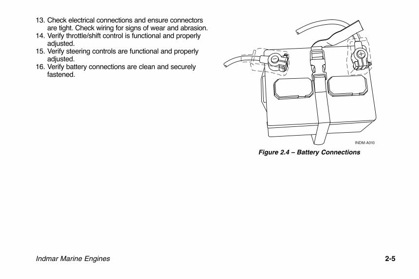
13. Check electrical connections and ensure connectorsare tight. Check wiring for signs of wear and abrasion.
14. Verify throttle/shift control is functional and properlyadjusted.
15. Verify steering controls are functional and properlyadjusted.
16. Verify battery connections are clean and securelyfastened.
Figure 2.4 – Battery Connections
INDM-A010
OME0502-08 Body.qxd:OM0502-05 Body.qxd 5/28/08 2:06 PM Page 2-5

2-6 Indmar Marine Engines
OME0502-08 Body.qxd:OM0502-05 Body.qxd 5/28/08 2:06 PM Page 2-6
Indmar Marine Engines 3-1
Explosive gasoline and battery fumes may
accumulate in your engine compartment.
Failure to properly ventilate fumes with the
bilge blower may result in explosive atmos-
phere resulting in death or serious injury to
you and your passengers.
Before starting engine operate bilge blower
at least 4 minutes and raise engine cover to
ventilate fumes. Inspect engine and compart-
ment for any fluid or fuel leaks.Failure to do
so can possibly result in fire and/or explo-
sion resulting in death or serious injury to
you and your passengers.
When refueling, make sure to open the motor box andrun the blower during and after the re-fueling operation.Failure to do so may result in fire or explosion and maycause death or serious injury.
Never remove or modify any components of
the engine’s fuel system. Tampering with fuel
components may cause a hazardous condi-
tion that could result in severe personal
injury or death. This work must be performed
by your dealer’s technicians.
HOW TO START YOUR ENGINE
1. Run the blower for 4 minutes to remove explosivegasoline and battery fumes from the engine compart-ment.
! !
Chapter 3ENGINE STARTING PROCEDURES
OME0502-08 Body.qxd:OM0502-05 Body.qxd 5/28/08 2:06 PM Page 3-1

3-2 Indmar Marine Engines
2. Perform the Daily Pre-Start checks. Refer toChapter 2, GeneralOperation and Warnings.
3. Move the shift controllever to the NEUTRALposition. Pull out theneutral safety lever (ifequipped). Withoutadvancing the throttlelever, turn the starter keyto START position.
NOTICE
Prime cold engine by moving throttle forwardand back two or three times. Then return toidle position before starting. A hot engine
does not require priming.
NOTICE
On carbureted engines it will be necessary tofeather the throttle until the engine warms up.
NOTICE
Because of theelectronic enginecontrols, there is no
need to advance the throttleto set an automatic choke.The throttle should be in theneutral position with theneutral detent button on theshift control box pulled out.
4. After the engine starts,release the key. Theengine will gradually slowfrom a fast idle to normalidle. If engine is cold, itwill operate at a slightlyhigher idle speed untilwarm-up is complete.Make sure that when youdo shift into gear that you are at idle speed (less than1100 RPM). Let engine warm up to normal operatingtemperature before accelerating.
Figure 3.1 – TypicalBlower Switch
Figure 3.2 – Start Position
ONBLOWER
OFF
INDM-A011
ON
STARTOFF
ACC
INDM-A012
OME0502-08 Body.qxd:OM0502-05 Body.qxd 5/28/08 2:06 PM Page 3-2
Indmar Marine Engines 3-3
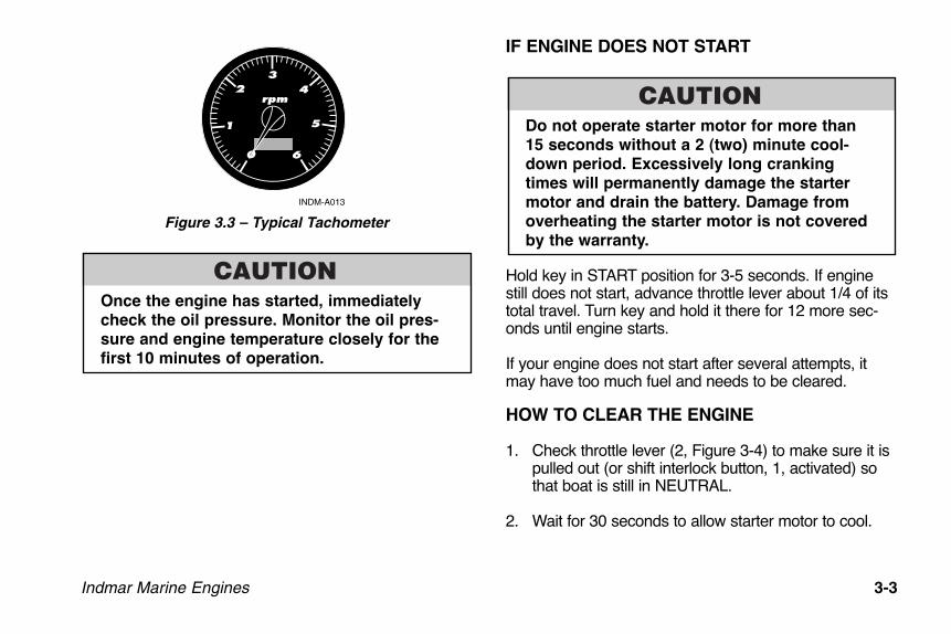
Figure 3.3 – Typical Tachometer
Once the engine has started, immediately
check the oil pressure. Monitor the oil pres-
sure and engine temperature closely for the
first 10 minutes of operation.
IF ENGINE DOES NOT START
Do not operate starter motor for more than
15 seconds without a 2 (two) minute cool-
down period. Excessively long cranking
times will permanently damage the starter
motor and drain the battery. Damage from
overheating the starter motor is not covered
by the warranty.
Hold key in START position for 3-5 seconds. If enginestill does not start, advance throttle lever about 1/4 of itstotal travel. Turn key and hold it there for 12 more sec-onds until engine starts.
If your engine does not start after several attempts, itmay have too much fuel and needs to be cleared.
HOW TO CLEAR THE ENGINE
1. Check throttle lever (2, Figure 3-4) to make sure it ispulled out (or shift interlock button, 1, activated) sothat boat is still in NEUTRAL.
2. Wait for 30 seconds to allow starter motor to cool.
rpm
INDM-A013
1
23
4
5
60
OME0502-08 Body.qxd:OM0502-05 Body.qxd 5/28/08 2:06 PM Page 3-3

3-4 Indmar Marine Engines
Figure 3.4 – Typical Shift/Throttle Lever
3. Disengage the shift interlock. Advance throttle leverto full throttle position and hold. Hold key in STARTposition for no more than 10 seconds to clear extragasoline from the engine. When engine starts, imme-diately return throttle handle to IDLE position.
4. If it does not start, wait two minutes and try thesequence again.
ENGINE RESTART
1. If your engine is already warm and will not re-start,turn key to ON position and wait for about 20 sec-onds (not necessary with carbureted engine).
2. Make sure that your throttle lever is in NEUTRAL.
3. Turn key OFF. Try to start engine again. If it does not start disengage the shift interlock and advancethrottle to about 1/4 while holding key in the STARTposition. (Remember, you should only hold key instart position for 12 seconds at a time.) When enginestarts, release the key and immediately return throttleto IDLE position.
NOTICE
Your engine is designed to work with thestandard electronics installed in your boat. Ifyou add electrical components or acces-
sories, you could change fuel injection controls foryour engine or could exceed the amperage capacityof the wiring and protection system. Before addingelectrical equipment, consult your Indmar dealer.
INDM-A016
2
1
OME0502-08 Body.qxd:OM0502-05 Body.qxd 5/28/08 2:06 PM Page 3-4

Indmar Marine Engines 4-1
DAILY ROUTINE
1. Open the engine cover and check the bilge for water; pump bilge dry. Excessive amounts of water can indicate leakage problems from shaft/rudder logs, thru-hull fittings, loose or damagedhoses or hull damage. Excess water in the bilge willdamage engine components (starters, alternators,transmissions, etc.).
Do not allow excessive amounts of water to
remain in the bilge. Component damage due
to water is not covered by the warranty.
2. Follow the starting procedures outlined in Chapter 3,Engine Starting Procedures.
Don’t forget to run your engine blower for at
least 4 minutes before cranking engine.
Failure to do so may result in fire and/or
explosion resulting in death or serious per-
sonal injury.
3. Once the engine is started, allow it to reach operat-ing temperatures of at least 120°-140° F (49˚-60˚ C)before accelerating to speeds above 3000 RPM.
Figure 4.1 – Typical Temperature Gauge
engine
INDM-A015
80 240°F
160
Chapter 4NORMAL OPERATION
OME0502-08 Body.qxd:OM0502-05 Body.qxd 5/28/08 2:06 PM Page 4-1
4-2 Indmar Marine Engines
4. Monitor your gauges and warning lights frequently toensure that engine temperatures and pressures arewithin the proper ranges.
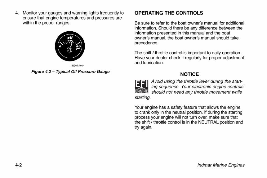
Figure 4.2 – Typical Oil Pressure Gauge
OPERATING THE CONTROLS
Be sure to refer to the boat owner’s manual for additionalinformation. Should there be any difference between theinformation presented in this manual and the boatowner’s manual, the boat owner’s manual should takeprecedence.
The shift / throttle control is important to daily operation.Have your dealer check it regularly for proper adjustmentand lubrication.
NOTICE
Avoid using the throttle lever during the start-ing sequence. Your electronic engine controlsshould not need any throttle movement while
starting.
Your engine has a safety feature that allows the engineto crank only in the neutral position. If during the startingprocess your engine will not turn over, make sure thatthe shift / throttle control is in the NEUTRAL position andtry again.
oil
INDM-A014
0
40
80psi
OME0502-08 Body.qxd:OM0502-05 Body.qxd 5/28/08 2:06 PM Page 4-2

Indmar Marine Engines 4-3
Most boats have an engine safe-ty switch (1, Figure 4-3) that canbe activated if the driver movesfrom the helm position. If youexperience a “no start” condition,verify that this switch has notbeen disabled. If the tether cordis pulled from the switch, it dis-ables the ignition system so theboat cannot start.
Use caution while operatingshift lever. Shift only while theengine is at idle.
Figure 4.3 – Typical Tether Cord and Safety Switch
Avoid using the throttle when in reverse.
This can force water backwards into the
exhaust system and into the engine cylinders
with major damage.
HYDROSTATIC LOCK: If water collects in the
engine cylinder for any reason, it can cause
hydrostatic lock, not allowing the pistons in
the engine to move properly. Hydrostatic
lock can severely damage your engine which
is not covered by your warranty.
UNUSUAL VIBRATION
If your engine is used in a direct coupled application(inboard) you need to know that damage to the drive line(propeller, shaft, strut and coupling) can cause vibration.You may feel vibration if damage is severe. Vibration inthe drive line will cause excessive wear on transmissionand engine components.
If you believe you hit something with the propeller, or ifyou notice excessive vibration, see your dealer. Damageto your engine, drive line, or transmission caused byvibration is not covered by your warranty.
INDM-A017
1
OME0502-08 Body.qxd:OM0502-05 Body.qxd 5/28/08 2:06 PM Page 4-3

4-4 Indmar Marine Engines
FUEL SYSTEM
The Indmar fuel system uses high quality marine gradecomponents. These components will tolerate smallamounts of water without sustaining damage. Yourengine will misfire and run poorly, however, if water is inthe fuel. Use caution when re-fueling not to allow waterto enter the fuel system. If you suspect your fuel is watercontaminated, consult your dealer and avoid that fuelsource in the future.
Do not attempt to repair or replace any compo-
nents of the fuel system. They are special
marine parts and may require special service
tools. You could damage the fuel system by
not using specified tools. This could cause a
fire or explosion and subsequent death or seri-
ous personal injury to you or your passengers.
See your dealer for assistance with fuel system repairs.
BATTERY
Your engine uses a special 12-volt marine battery. If areplacement is needed, use only a marine battery withminimum 650 cold cranking amps at 0° F (-18° C).
Before disconnecting the battery, make sure the batteryswitch (if equipped), ignition key and all accessories arein the OFF position.
Be sure to connect cables properly:• Black cable to the negative or (-) post• Red cable to the positive or (+) post
Figure 4.4 – Typical Marine Battery
INDM-A010
OME0502-08 Body.qxd:OM0502-05 Body.qxd 5/28/08 2:06 PM Page 4-4

Use caution when connecting the battery
cables. Improperly connecting the battery
cables or using the wrong battery type can
damage electrical components. These dam-
ages are not covered by your warranty.
“SERVICE REQUIRED” OR “CHECK ENGINE”
INDICATOR (EFI ENGINES ONLY)
Some boats are equipped with a digital dash which dis-plays the words “SERVICE REQUIRED” and/or“CHECK ENGINE,” and some boats are equipped witha Check Engine light. This alerts you when the ECM(Engine Control Module) detects a possible engine prob-lem. If the indicator goes on, return to dealer for service.
Figure 4.5 – Typical Check Engine Light
If any of the following conditions is noted:• Low Oil Pressure• High Coolant Temperature• High Transmission Oil TemperatureEFI engines may enter a Power Reduction mode. Powerreduction limits the engine speed to a “safe maneuver-ing” speed of about 2000 RPM. This mode is intended toallow the driver to get out of harm’s way and to reachsafe harbor for engine service.
If the check engine indicator should go on, or if theengine enters the Power Reduction mode, you shouldhave your dealer check the engine as soon as possible.
Schedule engine service at once when this
light is illuminated. Failure to have your
engine serviced when a check engine light
signal is given, may cause damage to your
engine or your emissions system.
The ECM also provides for a tapered engine RPM reduc-tion if engine coolant temperature approaches the highoperating limit. If the coolant temperature exceeds 176° F(80° C), the engine RPM is gradually reduced until a safetemperature is reached. If the engine RPM shoulddecrease due to high coolant temperature, stop theengine and inspect the raw water intake, sea cock andsea strainer (if equipped) and hoses for blockage or prob-lems.
CHECKENGINE
INDM-A018
Indmar Marine Engines 4-5
OME0502-08 Body.qxd:OM0502-05 Body.qxd 5/28/08 2:06 PM Page 4-5

4-6 Indmar Marine Engines
CHECK TRANSMISSION LIGHT
If the engine is equipped with the Walters V-Drive trans-mission, there may also be a Check Transmission light. Iflow oil pressure is sensed in the V-Drive, the light will goon indicating the problem. Under normal operation, thelight will stay lit at idle and slow speed operation untilenough pressure is produced (1200 RPM ± 400 RPM).Extended cruising or trolling at low RPM is not harmful,even if the light is lit, provided that the V-Drive oil level issufficient. If the oil level is normal and the light stays litabove 2000 RPM, take the boat to your Indmar dealerfor service.
ENGINE COOLING
Raw water cooled engines have two water pumps. Onecirculates water throughout the engine. The other pumpuses water from the sea, lake or river to feed raw waterto the engine. This raw water pump is designed to usethe water it pumps to lubricate its impeller. Do not run theengine unless the boat is in water. If you run the enginewith the boat out of the water, the water pump may bedamaged, causing your engine to overheat or start a fire.
Figure 4.6 – Raw Water Pump
Running engine without adequate cooling
can cause engine to overheat and may result
in fire, explosion, death and/or personal seri-
ous injury.
INDM-A019
OME0502-08 Body.qxd:OM0502-05 Body.qxd 5/28/08 2:06 PM Page 4-6

Indmar Marine Engines 4-7
The rubber water pump impeller in the water
pump can be damaged from running dry or
by picking up sand or silt through the water
intake. Inspect your water pump impeller
annually or more often if you operate your
boat in shallow water or run it aground.
Impeller failure will result in an overheated
engine.
Running your engine with your boat out of
water will damage or ruin your engine.
Damage to your engine caused by overheat-
ing is not covered by your warranty.
Running the engine during the RPM reduc-
tion phase may cause severe damage to your
engine.
• Monitor the temperature and oil gauges continuously.• If the temperature rises past 200° F (93° C), or your
oil pressure drops below 4 psi (41 kPa), STOP THEENGINE IMMEDIATELY.
Damage due to running the engine with excessive tem-perature or low oil pressure is not covered by your war-ranty.
EXHAUST HOSES
Exhaust hoses on most boats carry exhaust gases fromthe engine outside of the boat. These hoses carry waterthat has been used to cool the engine. This water keepsthe hoses cool and prevents them from melting.
The engine exhaust from this product con-
tains chemicals known to the State of
California to cause cancer, birth defects or
other reproductive harm.
OME0502-08 Body.qxd:OM0502-05 Body.qxd 5/28/08 2:06 PM Page 4-7

4-8 Indmar Marine Engines
Carbon monoxide gas (CO) is colorless,
odorless and extremely dangerous. All
engines and fuel burning appliances produce
CO as exhaust. Direct and prolonged expo-
sure to CO will cause BRAIN DAMAGE or
DEATH. Signs of exposure to CO include
nausea, dizziness and drowsiness. Ensure
adequate ventilation to prevent accumulation
of CO in the boat.
Monitor the engine temperature gauge frequently. If yourengine overheats, carefully inspect the exhaust hoses fordamage. Damaged hoses can allow carbon monoxidegas to enter your boat.
SELECTING A PROPELLER
For best engine performance and longevity, the wide-open-throttle (WOT) engine operation must be near thetop of, but within, the specified WOT operating range. Toadjust the WOT operating range, you must select a pro-peller (propping) with the proper diameter and pitch. Thepropeller which was supplied with your boat was chosenby the boat builder for best all-around performanceunder average conditions.
Load, weather, altitude and boat condition all affectWOT engine operation. If you use your boat for severaldifferent applications such as wakeboarding, barefootingand cruising, it may be necessary to have 2 or more pro-pellers which will allow the engine to operate in the WOTrange for each application.
Propping the boat should be done after engine break-inand the initial 10 hour dealer check. The boat should beloaded the way it would normally be for each application.For instance, if you are propping for wakeboarding, fillthe ballast tanks if equipped and add all the people andgear you would normally expect to carry in the boat.Take the boat out and after warm-up, run it at wide-open-throttle and note the maximum RPM. EFI Engines areequipped with RPM limiters to prevent over-revving. Takenote if the RPM limiter is activated.
If the WOT RPM is higher than the maximum RPM inyour engine’s WOT operating range, the boat is under-propped. Install a higher pitched propeller to reduceWOT RPMs. An engine that is over-revving may quicklyexperience catastrophic damage.
If the WOT RPM is lower than the minimum RPM in yourengine’s WOT operating range, the boat is over-propped.Install a lower pitched propeller to increase WOT RPMs.
! !
OME0502-08 Body.qxd:OM0502-05 Body.qxd 5/28/08 2:06 PM Page 4-8

Indmar Marine Engines 4-9
An engine that is under-revving is lugging. Luggingplaces tremendous loads on the pistons, crankshaft andbearings and can cause detonation, piston seizure andother engine damage.
Elevation and weather also have a very noticeable effecton the wide-open-throttle power of an engine. Since air(containing oxygen) gets thinner as elevation increases,the engine begins to starve for air. Humidity, barometricpressure and temperature have a noticeable effect onthe density of air since heat and humidity thin the air.This phenomenon can become particularly apparentwhen an engine is propped out on a cool dry day in
spring and later, on a hot, humid day in summer, doesnot have the same performance. Although some per-formance can be regained by dropping to a lower pitchpropeller, the basic condition still exists. The propeller istoo large in diameter for the reduced power output. Anexperienced marine dealer can determine how muchdiameter to remove from a lower-pitch propeller for spe-cific high-elevation locations.
Indmar suggests that if you do require a different pro-peller, consult the dealer you bought the boat from. Thedealer is best equipped to help with the selection of thecorrect propeller for your application(s).
OME0502-08 Body.qxd:OM0502-05 Body.qxd 5/28/08 2:06 PM Page 4-9

4-10 Indmar Marine Engines
OME0502-08 Body.qxd:OM0502-05 Body.qxd 5/28/08 2:06 PM Page 4-10
Indmar Marine Engines 5-1
WHAT TYPE OF GASOLINE TO USE
All carbureted and standard EFI engines run on unleadedfuel of 89 octane or higher. The LS2 and LS7 require 91octane or higher. Indmar recommends purchasing fuelfrom a supplier that advertises that the fuel meets “TOPTIER” specifications. This fuel has additives and deter-gents that will reduce the build-up of deposits in theengine.
The intention of the TOP TIER Detergent Gasoline stan-dards is to create a winning situation for gasoline retail-ers, engine manufacturers and boat operators. Currently,many gasoline retailers provide fuels with lower-qualityadditive packages that can build up deposits on fuel injec-tors and on intake valves. Others can build up deposits incombustion chambers and may lead to intake valve stick-ing. These lower levels of additives can have negativeimpacts on engine performance and vehicle responsive-ness. For a current list of gasoline retailers supplying TOPTIER gasoline, go to www.toptiergas.com and click onRETAILERS.
Gasoline vapors are highly flammable and
explosive.
• Never smoke while refueling. Keep sparks
and flames away from fuel.
• Only refuel in well ventilated area.
• Never overfill fuel tank.
• Stop engine before fueling.
• Swallowing or inhaling gasoline or fumes
is dangerous. Seek medical attention.
• Gasoline spills on your skin should be
washed immediately with soap and water.
If gasoline spills on clothing, change
clothing immediately.
* Avoid spilling gasoline. Clean spills with
dry cloth and dispose properly.
Chapter 5FUEL
OME0502-08 Body.qxd:OM0502-05 Body.qxd 5/28/08 2:06 PM Page 5-1

5-2 Indmar Marine Engines
Figure 5.2 – Inspecting Fuel Lines
Frequently inspect fuel lines and connec-
tions for leaks or deterioration.
Indmar recommends the regular use of Sta-Bil fuel stabi-lizer for boat users that consume less than a tank of fuelevery two weeks. Today’s fuels are more susceptible todegradation and the use of a quality stabilizer will helpensure fewer problems for the occasional boater.
If your boat has not been used for more than 30 dayswith fuel in the tank (even stabilized fuel), the enginemay run poorly until the “old” fuel is used up. Indmar willnot pay for repairs to carburetors or fuel injection compo-nents that are inoperable or damaged from old and/orpoor quality fuel.
USING OXYGENATED FUELS OR FUELS WITH
ALCOHOL
MBTE (methyl butyl tertiary ether) is an oxygenate andoctane enhancer. This compound may be blended withfuel. Fuel that is no more than 15% MBTE is acceptablefor use in your Indmar engine.INDM-A022
OME0502-08 Body.qxd:OM0502-05 Body.qxd 5/28/08 2:06 PM Page 5-2

Indmar Marine Engines 5-3
Ethyl alcohol, ethanol or grain alcohol is acceptable aslong as it is a blend and the blended fuel contains nomore than 10% ethanol.
Fuels that are blended to contain methanol
or wood alcohol should not be used in
Indmar engines. These fuels can corrode
metal parts in your fuel system and engine.
Fuels that contain methanol will damage
your engine. Damage caused by the use of
fuels that contain methanol is not covered by
your warranty.
FUELS IN OTHER COUNTRIES
If you operate your Indmar engine outside the USA orCanada, unleaded fuels may be difficult to obtain.Leaded fuels must not be used in engines with catalyticconverters or serious damage will occur.
OME0502-08 Body.qxd:OM0502-05 Body.qxd 5/28/08 2:06 PM Page 5-3

5-4 Indmar Marine Engines
OME0502-08 Body.qxd:OM0502-05 Body.qxd 5/28/08 2:06 PM Page 5-4

Indmar Marine Engines 6-1
GENERAL SERVICE NOTES
Your Indmar dealer is your best source for engine repairand maintenance. Indmar certified technicians attendongoing service training programs and have the properdiagnostic tools plus the latest specifications for yourengine.
Electrical, ignition and fuel system compo-
nents on Indmar engines comply with U.S.
Coast Guard rules and regulations to mini-
mize risks of fire or explosion. Use of
replacement electrical, ignition or fuel sys-
tem components, which do not comply to
these rules and regulations, could result in a
fire or explosion hazard and should not be
used.
Your safety depends on your use of marine parts. Whenservicing the electrical, ignition and fuel systems, it isextremely important that all components are properlyinstalled and tightened. If not, any electrical or ignitioncomponent could permit sparks to ignite fuel vapors fromfuel system leaks, if they existed.
Since marine engines are expected to operate at nearfull-throttle for most of their life, and to operate in freshand salt water environments, many special parts andfasteners are used which are quite different from stan-dard automotive parts. Many parts are made from spe-cial corrosion resistant materials while other movingparts are heavy-duty for continuous, high RPM duty. Ifyou perform minor service procedures, make sure to usegenuine Indmar parts for marine use.
! !
Chapter 6MAINTENANCE
OME0502-08 Body.qxd:OM0502-05 Body.qxd 5/28/08 2:06 PM Page 6-1

6-2 Indmar Marine Engines
• You can be injured if you try to work on your
marine engine without knowing enough
about your engine.
• Be sure you have the knowledge, experience
and the correct replacement parts BEFORE
you attempt any repairs.
• Be sure all fasteners you use are approved
and rated for marine use. Use of improper
parts can cause component or engine failure
which may result in death or serious person-
al injury.
If the temperature falls below the freezing
point (32°F, 0°C) the raw water portion of
your engine’s cooling system must be
drained. See Chapter 7 - Storage and Winter
Lay-up. Failure to drain the cooling system
will result in severe damage to your engine
and other cooling system components.
Special maintenance procedures are required
for engines that are operated in brackish or
salt water. See the Salt Water Operation por-
tion of this chapter for details.
Never operate engine without adequate water
supply to the raw water pump. Failure to
properly cool engine will cause severe
engine damage and void your warranty.
Special Note for Boats Operating on Small Ski Lakes
Some operators choose to use their boats exclusively onsmall ski lakes where they never get an opportunity torun their engines for extended amounts of time (15 min-utes or more) in the upper RPM range (above 4000RPM). Many of these engines are also exposed toextended periods of idling RPM below 1000.
Boats used in these conditions often have engines thatmay suffer from fuel dilution of the motor oil. This condi-tion is commonly referred to as “making oil” because theoil level on the dipstick appears to rise over time. Boatsthat are operated in these severe conditions will berequired to have more frequent oil and filter changes(every 25 hours instead of every 50 hours).
OME0502-08 Body.qxd:OM0502-05 Body.qxd 5/28/08 2:06 PM Page 6-2

Indmar Marine Engines 6-3
Scheduled Maintenance Chart
FIRST EVERY EVERY EVERY EVERY 300 EVERY10-20 25 50 100 HOURS or 2
ITEM SERVICE HOURS HOURS1 HOURS HOURS ANNUALLY YEARS
Engine Oil & Filter Change X X XZF Transmission Fluid Change X XWalters V-Drive Oil Change X XEngine Coolant Change XSpark Plugs* Replace XEngine Timing* Check X XEngine* Tune Up XFlame Arrestor Clean/Change XBelts Inspect X X XShaft Alignment Check X XSpark Plug Wires* Inspect XRaw Water Pump Impeller Inspect X X ReplaceBreather Hose* Clean XPCV Valve* Replace XStarter Bendix* Grease X XHeat Exchanger Inspect/Clean XZinc Anodes Inspect X
* Services best accomplished by your Indmar dealer.1 Severe use applications (see special note on previous page)
OME0502-08 Body.qxd:OM0502-05 Body.qxd 5/28/08 2:06 PM Page 6-3

6-4 Indmar Marine Engines
ENGINE OIL
Checking Oil
Figure 6.1 – Engine Oil Dipstick Location
Check the oil level with the dipstick every time you getfuel. To get an accurate reading, your engine should bewarm and the boat should be level. For best results waitabout 2 minutes after you turn off the engine to allow theoil to drain into the oil pan, giving you a more accuratereading.
Figure 6.2 – Dipstick
1. Pull dipstick from engine.2. Wipe oil off stick with clean towel/cloth.3. Insert dipstick completely into the dipstick tube.4. Remove dipstick and read oil level.5. After reading is complete, return dipstick to tube.6. Add oil if necessary.
Adding Oil
If oil level on the dipstick reads below the ADD mark,add only enough oil to return level to FULL mark.
Figure 6.3 – Engine Oil Fill
INDM-A025
ADDOPERATING RANGE SEE OWNERS MANUA
INDM-A003
INDM-B001
OME0502-08 Body.qxd:OM0502-05 Body.qxd 5/28/08 2:06 PM Page 6-4

Indmar Marine Engines 6-5
Do not overfill. If your oil level is above the
full mark on the dipstick, the engine may be
damaged.
Indmar uses and recommends Pennzoil Marine 15W40in all 5.7L, 6.0L and 6.2L (383) engines and PennzoilHeavy Duty 40W in all 7.4L (454), 8.1L (496) and 8.2L(502) engines. This oil meets the API Service CI-4, CH-4,CG-4, CF-4, and CF/SL. If engine is to be used in condi-tions below 20 F (-7 C), use Pennzoil 10W30 meeting theabove API specifications. Note the special instructions forthe LS7 engine.
The use of engine oil other than the recom-
mended viscosity with an API SJ/CG4 desig-
nation can cause engine damage. Damage to
your engine caused by the use of improper
oils is not covered by your warranty.
Special Oil Instructions for Malibu LS7 Engine
Oil Requirement
The Malibu LS7 by Indmar oil requirement is differentthan the requirement for any of our other engines. TheLS7 comes from Indmar filled with 5W30 Mobil 1 fullysynthetic oil. Indmar strongly recommends the continueduse of this oil for subsequent oil changes on this veryspecial engine.
Checking the Oil Level
The Malibu LS7 by Indmar is a unique high performanceengine with a dry-sump lubrication system. Since theengine does not have a conventional oil pan like mostengines, the procedure for checking the engine oil is a lit-tle different.
Do not check the engine oil cold. The engine must bewarmed up. Cold oil will not give a correct oil level read-ing. After the engine is warmed up to at least 160°F(72°C), shut off the engine. Checking the oil with theengine running will result in an incorrect reading. Wait for5 minutes (but not more than 20 minutes), to allow the oilto drain and settle. Make sure boat is sitting level as pos-sible. For convenience, Indmar suggests you check theoil at the end of each session rather than the beginningof each day as you would with a conventional engine.
OME0502-08 Body.qxd:OM0502-05 Body.qxd 5/28/08 2:06 PM Page 6-5

6-6 Indmar Marine Engines
Pull the dipstick with the yellow handle from the reser-voir, and clean it with a lint-free cloth. Then push it backin all the way until it stops. Remove it again, keeping thetip down, and note the oil level on the crosshatchedarea. An oil level within the crosshatched area is normal.If the level is below the crosshatched area, add 1 quart(0.96 L) of 5W30 Mobil 1 synthetic oil through the blackoil reservoir fill cap and take another reading.
Do not overfill the reservoir, as this mayresult in excessive oil consumption. Oil lev-els above the crosshatched area maydegrade lubrication system performance. Inthe event of an over filling, some oil will bedischarged through the dry sump tank ventand wet the flame arrestor and front of themotor.
Oil Change Procedure
NOTICE
Indmar strongly recommends that you take your boatto your authorized dealer to perform this critical serv-ice.
Materials Required:8 quarts 5W30 Mobil 1 Synthetic OilPennzoil PZ3 Oil FilterOil Change Pump/Oil Suction Device
The oil change interval for the LS7 is the same as anyother Indmar engine. The first oil and filter change shouldbe done after approximately 10 hours of operation.Subsequent oil changes should be done every 50 hoursor annually, whichever comes first.
To remove the oil from the engine requires accessingtwo oil drain locations. If you have an early model thatonly has one oil drain hose, remove the cap from the oildrain hose and either drain or pump the oil from the oilpan through the hose. The hose is connected to the oilpan where approximately 1 quart of oil will be retained.Once the residual oil has been removed from the oil pan,reinstall the drain cap and secure the hose.
Next, remove the fill cap from the oil tank. You will needto use a pump or oil suction device to remove the oilfrom the tank. Just run the pump or suction line all theway to the bottom of the tank and remove all of the oil.
If the engine you are changing the oil on has two oildrain hoses, you must drain or pump the oil from the oilpan (as above) from one of the hoses. The other hose isconnected to a different fitting on the front of the oil panthat will drain oil tank.
OME0502-08 Body.qxd:OM0502-05 Body.qxd 5/28/08 2:06 PM Page 6-6

Indmar Marine Engines 6-7
Once the oil has been removed from the engine andreservoir, fill a new PZ3 oil filter with 5W30 Mobil 1 syn-thetic oil and install it on the remote filter head. Tightenper instructions on the filter. Pour the remainder of the 8Quarts of 5W30 Mobil 1 through the oil fill cap in the topof the dry sump reservoir. The total service fill, with a fil-ter, is 8 quarts (7.57 L) of 5W30 Mobil 1 synthetic engineoil.
Replace the oil fill cap and start the engine. Let it run atidle for at least 15 seconds to circulate the fresh engineoil through the lubrication system. (This is similar to run-ning an engine after a radiator fill, to purge air from thesystem.)
Check the oil level according to the instructions above.The oil change is now complete.
Synthetic Oil
Synthetic oil that meets our viscosity requirements andAPI SL/SJ/CI-4, CH-4, CG-4 is acceptable to use after100 hours of operation with the recommended oil. The useof synthetic oil does not change the requirement of 50hour (25 hour in severe conditions) oil change intervals.
Changing Oil
Change your engine oil after the first 10-20 hours ofoperation. Then change oil every 50 hours (25 in severe conditions) or annually, whichever comes first. To maximize engine life, change the oil filter at every oil change.
Figure 6.4 – Oil Filter
Indmar recommends all engine maintenance proceduresbe performed by your dealer, including oil changes. Ifyou must perform the oil change yourself, operate theengine to full operating temperature.
INDM A009
OME0502-08 Body.qxd:OM0502-05 Body.qxd 5/28/08 2:06 PM Page 6-7

6-8 Indmar Marine Engines
Engine oil is hot. Be careful not to burn yourself.
1. With the boat level on trailer, remove the hull or gar-board drain plug and insert QuickDrain through thehull opening (outside of hull).
2. Remove QuickDrain hose cap and let oil flow intoused oil container. When all oil has drained, replacecap and return QuickDrain to storage position.
3. Replace the hull or garboard drain plug. Position asuitable container under the oil filter.
4. Unscrew and remove the oil filter; ensure that filterseal is removed with oil filter. Wipe up any spilled oil inthe bilge and dispose of properly.
5. Fill a new Pennzoil Marine oil filter about 1/2 full withclean engine oil. Lightly lubricate the oil filter gasketand “spin on” the filter until the gasket makes contact.Hand-tighten filter 1/4 to 1/2 turn after contact.
6. Add the new oil through the cap located on the enginevalve cover. Fill only to the FULL mark of dipstick.
7. After initial start up, always carefully inspect oil drainplug and oil filter gasket area for leaks.
8. Stop the engine and re-check oil level. Add if neces-sary.
Oil Additives
Do not use oil additives. Indmar engines do not need oiladditives. Use of recommended oil, along with regular oiland oil filter changes, will protect your engine adequately.
Disposing
Used engine oil contains dangerous chemicals and isconsidered a hazardous waste. Do not allow used oil toremain on your skin for any length of time. Make certainto drain all free flowing oil from the filter prior to disposal.Recycle used oil by taking it to a collection center. If youhave a problem disposing of used oil, ask your Indmardealer or service station for the name of a local oil recy-cling center for proper disposal.
• Prolonged and repeated contact with used
engine oil may cause skin cancer.
• Avoid direct skin contact with used oil. If skin
contact is made, wash thoroughly with soap
or hand cleaner as soon as possible.
• Keep used engine oil out of reach of children.
• Used engine oil is a hazardous material.
Dispose of properly.
OME0502-08 Body.qxd:OM0502-05 Body.qxd 5/28/08 2:06 PM Page 6-8

Indmar Marine Engines 6-9
ENGINE FLAME ARRESTOR
Your engine is equipped with a U.S. Coast Guardapproved flame arrestor. Its purpose is to contain anybackfire that may occur during the operation of yourengine. Because an inboard engine is completelyenclosed, an uncontained backfire can be extremelydangerous.
Figure 6.5 – Flame Arrestor
Periodically inspect flame arrestor to prevent clogging bydirt or corrosion. There are two types of flame arrestorsused in Indmar engines, metal and paper.
Metal TypeThe metal flame arrestor is cleaned using a mild partwashing solvent. Using solvent, clean the flame arrestorthoroughly and blow dry. The metal flame arrestor must
dry completely before it is returned to the engine.
K&N Element Type Flame ArrestorIf your engine is eqipped with a K&N high performanceelement type flame arrestor, special procedures arerequired. Special servicing instructions for this flamearrestor can be found on the K&N website,www.knfilters.com/cleaning.htm.
When cleaning or replacing the flame arrestor, clean thebreather hose and replace the PCV valve at the sametime.
Do not remove the flame arrester at any time
when the engine is being started or run as it
may result in fire, explosion and death or
serious personal injury.
ENGINE COOLING
Running engine without adequate cooling
can cause engine to overheat and may result
in fire, explosion, death and/or personal
serious injury.
INDM-A027
OME0502-08 Body.qxd:OM0502-05 Body.qxd 5/28/08 2:06 PM Page 6-9

6-10 Indmar Marine Engines
Fresh water cooled engines are shipped from
the Indmar factory filled with a 50/50 mix of
Sierra brand antifreeze and water. This mix-
ture provides freeze protection down to –26° F
(-32° C). If the temperature in your area is
expected to go below this level of protection,
see your Indmar dealer to have the antifreeze
mixture adjusted for your needs.
Running your engine with your boat out of
water will damage or ruin your engine.
Damage to your engine caused by overheat-
ing is not covered by your warranty.
Most engines are cooled by the raw water outside of theboat (Open Cooling System). For this reason, do notstart the engine when the boat is out of the water withoutan engine flushing device available from your Indmardealer.
With Open Cooling Systems, if your engine is used insalt, brackish, dirty or polluted water, the cooling systemmust be flushed with clean water immediately to preventcorrosion and blockage in the cooling system.
Open Cooling Systems usually consist of a raw waterintake on the bottom of the boat, a raw water pump, abelt driven marine water pump, a thermostat to regulateengine temperature, and various connecting hoses. Theraw water pump pulls outside water through the intake,circulates the water through the engine and then discharges it overboard through a hose or with theengine exhaust.
Fresh Water (Closed) Cooling Systems
Some engines havea closed fresh watercooling system. In thefresh water systemthe cooling watercontains anti-freezeand re-circulatesthroughout theengine. If your engineis equipped with aheat exchanger tank,it has a fresh watercooling system. Rawwater is pulledthrough the intakeand flows throughchambers in the heat exchanger and then dischargedoverboard with the engine exhaust.
HOT
COLD
INDM-B002
1
Figure 6.6 – Overflow Tank
OME0502-08 Body.qxd:OM0502-05 Body.qxd 5/28/08 2:06 PM Page 6-10

Indmar Marine Engines 6-11
Check coolant level every time you check your oil. Thelevel in the coolant recovery tank should be maintainedat the “Full Cold” mark (1, Figure 6.6) when the engineis cold.
To avoid possible skin burns, the engine must
be turned “OFF” and cool enough so no heat
is registered on the temperature gauge. Only
after the engine is completely cooled is it safe
for you to remove the coolant reservoir cap to
check the level. Failure to follow procedure
may result in death or serious personal injury.
• Failure to maintain the coolant at the proper
level can cause engine damage. Your war-
ranty will not cover engine damage due to
overheating or any other cause associated
with improper coolant levels.
• Use only propylene glycol coolant. Use of
any other coolant or mixing coolant types
can cause engine damage. Damage to your
engine from use of any other type of coolant
is not covered by warranty.
• The coolant system should be flushed and
coolant replaced every two years. This
should be performed by a qualified Indmar
service technician.
When adding coolant, add only Sierra brand propyleneglycol in an appropriate mixture with distilled water inaccordance with the directions on the container. Do notoverfill the tank. Do not mix anti-freeze types.
If cooling system is completely empty, see your Indmardealer for assistance immediately to purge system.Purging the system is a difficult procedure that is not rec-ommended for the boat owner.
Salt Water OperationAll Indmar Marine engines are capable of operating inbrackish or salt water environments as long as certainprecautions and maintenance procedures are followed.Damage to the engine, both internal and external, that isa result of inadequate maintenance on an engine used insalt water will not be covered under the Indmar LimitedWarranty.
OME0502-08 Body.qxd:OM0502-05 Body.qxd 5/28/08 2:06 PM Page 6-11

6-12 Indmar Marine Engines
The following engines must not be operated in brackishor salt water environments unless equipped with aclosed cooling system which allows the use of anti-freeze coolant in the engine instead of raw water.
• Malibu Hammerhead 383• Indmar LS2
These engines use aluminum cylinder heads and/orblock assemblies which will be severely damaged fromsalt water corrosion if operated in brackish or salt water.See your Indmar dealer to install a closed cooling sys-tem if you have one of these engines and will operate itin salt water.
The following engine is equipped with a standard closedcooling system from Indmar:
• Malibu LS7
This engine can be operated in fresh water or salt waterwithout causing damage to the internal cooling passagesin the engine. The cooling passages in the exhaust man-ifolds are not part of the closed cooling system andalthough they are corrosion resistant, need to bechecked periodically for damage from salt water.
The remaining Indmar engines will tolerate occasionaluse in salt water but it is recommended that if the enginewill be used in salt water more that 25% of the time thatthe engine be equipped with a closed cooling system.
External CareYour engine has been carefully primed and painted toprotect it against rust and corrosion. To keep your enginelooking like new, Indmar recommends applying an anti-corrosion compound, such as Pennzoil Marine Z-MCorrosion Protectant and Lubricant. Regular application(every 3 months) of this Protectant, particularly onexposed metal surfaces, motor mounts and electricalconnections, will displace water and seal the surfacesagainst penetration by corrosive agents. Rinsing theengine with fresh water between applications of theProtectant will further protect the exposed surfaces.
INTERNAL (COOLING SYSTEM) CARE
Raw Water Cooling SystemsIf your engine is raw water cooled, water from whateverbody of water you are operating in is pumped throughthe cooling passages of the engine, exhaust manifoldsand exhaust risers. It is critical that the salt water beflushed from these cooling passages after use by run-ning fresh water through the cooling system. For moreconvenient flushing, ask your dealer about permanentlyinstalling a flushing device that allows easy connection ofa water hose.
OME0502-08 Body.qxd:OM0502-05 Body.qxd 5/28/08 2:06 PM Page 6-12

Indmar Marine Engines 6-13
Even with diligent flushing, certain exhaust system com-ponents called exhaust risers or exhaust elbows will besignificantly affected by salt water. These risers must beinspected by your dealer annually and replaced asrequired. It is not unusual to have to replace these risersevery two years on boats used exclusively in salt water.
Fresh Water Cooling – Half SystemsA fresh water cooling system that uses anti-freeze in theengine but raw water in the exhaust manifolds is referredto as a half-system. This is the most common type ofsystem installed on water-ski boats. Although the engineis protected, it is still important to flush the engine withfresh water to remove as much salt water as possiblefrom the raw water side of the cooling system as well asfrom the exhaust manifolds and risers. For more conven-ient flushing, ask your dealer about permanentlyinstalling a flushing device that allows easy connection ofa water hose.
Even with diligent flushing, certain cast iron exhaust sys-tem components called exhaust risers or exhaust elbowswill be significantly affected by salt water. These risersmust be inspected annually and replaced as required. Itis not unusual to have to replace these risers every twoor three years on boats used exclusively in salt water.
Some half system installations use the one piece alu-minum Tri-Y or ETX manifolds and do not have separaterisers or riser gaskets. These manifolds have shown tobe extremely resistant to salt water damage and shouldprovide extended service over the two piece cast ironsystems, but still need to be flushed regularly with freshwater to maintain their integrity.
Fresh Water Cooling – Full System – Salt Water
Series EnginesSome fresh water cooling systems are referred to as fullsystems. A full fresh water system includes the exhaustmanifolds as part of the system that is cooled with anti-freeze. Most commonly, a block-off plate is installedbetween the exhaust manifolds and exhaust risers andthe risers are cooled with raw water.
Because the risers are exposed to salt water they aresubject to corrosion. These risers must be inspected byyour dealer annually and replaced as required. It is notunusual to have to replace these risers every two yearson boats used exclusively in salt water.
Some Full Fresh Water Cooled engines equipped withETX or Tri-Y one piece exhaust manifolds do not haveseparate exhaust risers. Full FWC systems utilizing thosemanifolds use anti-freeze in the complete manifold/riserassembly and will not have the riser corrosion issuesassociated with the two piece manifold/riser assemblies.
OME0502-08 Body.qxd:OM0502-05 Body.qxd 5/28/08 2:06 PM Page 6-13

6-14 Indmar Marine Engines
Fresh Water Cooling – All SystemsAll fresh water cooling systems, whether they are half orfull systems, must be inspected and maintained annually,usually during winterization.
Heat Exchanger – Remove the end caps to drain andinspect the heat exchanger. Clean out any debris. Makesure you inspect the end caps for contour and cracksand replace the neoprene gaskets before putting theboat back in service. If you find rubber bits in theexchanger, check the rawwater pump impeller. Notethat if you use a clean-outrod, it should be softer thanthe copper tubes, andshould not be used to dis-lodge materials which arefirmly stuck to the tube sur-face, as this could damagethe tubes. The rod will assistin cleaning out bits of grass,zinc, shells, and similar materials which arejust lodged in the tubes.
Zinc Anodes – The sacrificial zinc anodes frequentlyspall, and there will probably be zinc bits in the exchang-er which should be cleaned out. Inspect the zinc anodeoften during use and replace when half gone.
Raw Water Pump – Replace the impeller if it is worn orover two years old. Since you must remove the impellerto inspect it, it is good practice to replace the impellerevery year as a routine. Be sure there are no impellerparts lodged in the hoses or elsewhere in the system asthey will eventually move to an inconvenient place andrestrict water flow. The raw water pump impeller shouldbe replaced every two years or whenever it is found to be worn or have damaged blades. Be sure to re-assemble with the proper gaskets.
Figure 6.8 – Raw Water Pump ImpellerINDM-A036
SACRIFICIAL ANODEREPLACE IF ANODE HAS
REDUCED TO 1/2 OF ORIGINAL SIZE
INDM-B007
Figure 6.7 – SacrificialAnode
OME0502-08 Body.qxd:OM0502-05 Body.qxd 5/28/08 2:06 PM Page 6-14
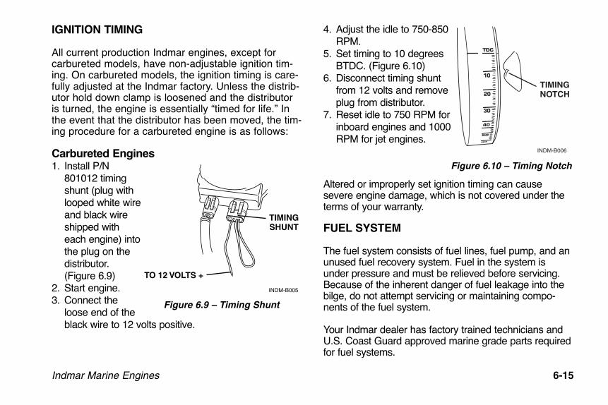
Indmar Marine Engines 6-15
IGNITION TIMING
All current production Indmar engines, except for carbureted models, have non-adjustable ignition tim-ing. On carbureted models, the ignition timing is care-fully adjusted at the Indmar factory. Unless the distrib-utor hold down clamp is loosened and the distributoris turned, the engine is essentially “timed for life.” Inthe event that the distributor has been moved, the tim-ing procedure for a carbureted engine is as follows:
Carbureted Engines1. Install P/N
801012 timingshunt (plug withlooped white wireand black wireshipped witheach engine) intothe plug on thedistributor.(Figure 6.9)
2. Start engine.3. Connect the
loose end of theblack wire to 12 volts positive.
4. Adjust the idle to 750-850RPM.
5. Set timing to 10 degreesBTDC. (Figure 6.10)
6. Disconnect timing shuntfrom 12 volts and removeplug from distributor.
7. Reset idle to 750 RPM forinboard engines and 1000RPM for jet engines.
Altered or improperly set ignition timing can causesevere engine damage, which is not covered under theterms of your warranty.
FUEL SYSTEM
The fuel system consists of fuel lines, fuel pump, and anunused fuel recovery system. Fuel in the system isunder pressure and must be relieved before servicing.Because of the inherent danger of fuel leakage into thebilge, do not attempt servicing or maintaining compo-nents of the fuel system.
Your Indmar dealer has factory trained technicians andU.S. Coast Guard approved marine grade parts requiredfor fuel systems.
INDM-B005
TIMINGSHUNT
TO 12 VOLTS +
Figure 6.9 – Timing Shunt
TIMINGNOTCH
INDM-B006
Figure 6.10 – Timing Notch
OME0502-08 Body.qxd:OM0502-05 Body.qxd 5/28/08 2:06 PM Page 6-15
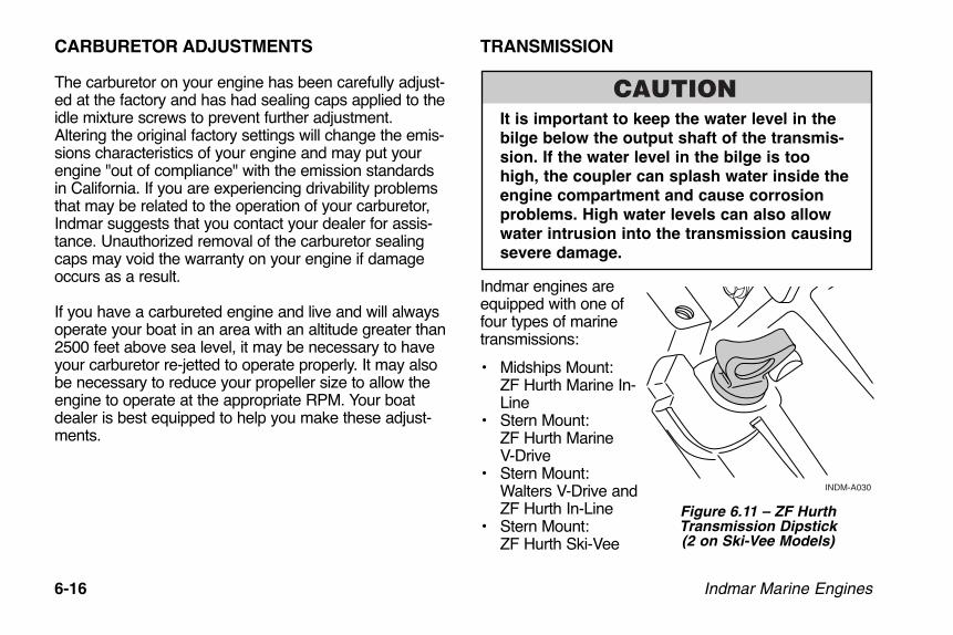
6-16 Indmar Marine Engines
CARBURETOR ADJUSTMENTS
The carburetor on your engine has been carefully adjust-ed at the factory and has had sealing caps applied to theidle mixture screws to prevent further adjustment.Altering the original factory settings will change the emis-sions characteristics of your engine and may put yourengine "out of compliance" with the emission standardsin California. If you are experiencing drivability problemsthat may be related to the operation of your carburetor,Indmar suggests that you contact your dealer for assis-tance. Unauthorized removal of the carburetor sealingcaps may void the warranty on your engine if damageoccurs as a result.
If you have a carbureted engine and live and will alwaysoperate your boat in an area with an altitude greater than2500 feet above sea level, it may be necessary to haveyour carburetor re-jetted to operate properly. It may alsobe necessary to reduce your propeller size to allow theengine to operate at the appropriate RPM. Your boatdealer is best equipped to help you make these adjust-ments.
TRANSMISSION
It is important to keep the water level in the
bilge below the output shaft of the transmis-
sion. If the water level in the bilge is too
high, the coupler can splash water inside the
engine compartment and cause corrosion
problems. High water levels can also allow
water intrusion into the transmission causing
severe damage.
Indmar engines areequipped with one offour types of marinetransmissions:
• Midships Mount: ZF Hurth Marine In-Line
• Stern Mount: ZF Hurth Marine V-Drive
• Stern Mount:Walters V-Drive andZF Hurth In-Line
• Stern Mount:ZF Hurth Ski-Vee
INDM-A030
Figure 6.11 – ZF HurthTransmission Dipstick(2 on Ski-Vee Models)
OME0502-08 Body.qxd:OM0502-05 Body.qxd 5/28/08 2:06 PM Page 6-16

Indmar Marine Engines 6-17
A separate owner’s manual cover-ing basic maintenance is providedwith each transmission. The trans-mission fluid must be changed andthe filter cleaned after the first 10-20 hours of operation and onceeach year thereafter. Refer to thetransmission owner's manual forinformation.
The transmission is water cooledby a heat exchanger connected tothe engine cooling system. Thetransmission fluid level should bechecked each time the engine oilis checked. Fluid level is to bemaintained at a level between the“Full” and “Add” marks on thetransmission dipstick.
Overfilling the transmission withfluid will cause the seals to leak,and eventually lead to overheating,while if there is too little fluid, overheating will result.
If the engine uses the Walters V-Drive, it is equipped witha ZF Hurth in-line transmission for shifting. Be aware thatthe Walters V-Drive uses motor oil for lubrication, whilethe ZF Hurth transmission uses Automatic TransmissionFluid. The Walters V-Drive also has a low oil pressure
sensor and a dashboard mounted light. If low oil pres-sure is sensed, this lamp will light indicating the problem.Shut down the engine and check the transmission fluidlevel. Refer to Chapter 6, Check Transmission Light formore information.
If transmission service is required, note the SerialNumber of the transmission stamped onto the ID plateon the top of the transmission housing. It is good prac-tice to note the serial number noted and keep it withother owner related information.
Checking/Adding Transmission Fluid
Check fluid only with engine OFF and boat floating level,or level on trailer. The transmission dipstick is located onthe top of the transmission. Dipsticks may be marked“ADD” and “FULL” or “H” and “L” (high and low); main-tain fluid level between the two marks.
Check level immediately after turning engine
off. Transmission fluid may be hot. Be care-
ful not to burn yourself.
HIGH
LOW
INDM-A039
Figure 6.12 – Walters V-Drive Dipstick
OME0502-08 Body.qxd:OM0502-05 Body.qxd 5/28/08 2:06 PM Page 6-17

6-18 Indmar Marine Engines
1. Remove the dipstick and wipe with a clean towel.2. Insert the dipstick completely (do not screw in
threaded dipstick to check fluid). Remove the dipstickand read fluid level.
3. Return dipstick after level check. Make sure it issecured in place.
4. If level is below “ADD” mark, add the proper fluiduntil it reaches the full mark. Add fluid through sametube as you removed the transmission dipstick.
Figure 6.13 – Walters V-Drive Dipstick Location
INDM-A031
OME0502-08 Body.qxd:OM0502-05 Body.qxd 5/28/08 2:06 PM Page 6-18

Indmar Marine Engines 6-19
TRANSMISSION MODEL RATIO CAPACITY FLUID TYPE
ZF Hurth In-Line ZF 45 D 1:1 1.7 qt (1.6L) Pennzoil Dexron II, III or MERCONZF Hurth In-Line ZF 45 A Various 2.12 qt (2L) Pennzoil 15W40ZF Hurth In-Line ZF 63 A 1.5:1 4.2 qt (4L) Pennzoil 15W40ZF Hurth V-Drive ZF 63 IV -- 4.2 qt (4L) Pennzoil 15W40
ZF Hurth Ski-Vee ZF 45 IV 1:1.462 2.12 qt (2L) Main Gearbox Pennzoil Dexron II, III or MERCON1.0 qt (1.06L) V-Drive Unit Pennzoil Dexron II, III or MERCON
Walters V-Drive RV-26D-71V -- 0.5 qt (0.5L) Pennzoil SAE 30 Motor Oil
Do not overfill the transmission. Overfilling
can damage the transmission. Damage to
your transmission due to too much or too
little fluid is not covered by your warranty.
ELECTRICAL SYSTEM
All Indmar engines are equipped with a 35 A circuit break-er (1, Figure 6-14) to protect the engine electrical systemand components from overload. If the engine will notcrank with the battery switch in the ON position, locate thered breaker reset button at the back of the engine. Firmlypush the red button until the breaker resets (an audibleclick will be heard). Start the engine.
Figure 6.14 – Breaker Reset ButtonINDM-A029
1
2
OME0502-08 Body.qxd:OM0502-05 Body.qxd 5/28/08 2:06 PM Page 6-19
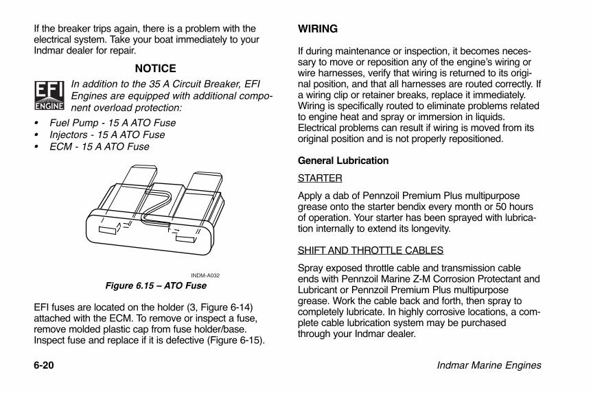
6-20 Indmar Marine Engines
If the breaker trips again, there is a problem with theelectrical system. Take your boat immediately to yourIndmar dealer for repair.
NOTICE
In addition to the 35 A Circuit Breaker, EFIEngines are equipped with additional compo-nent overload protection:
• Fuel Pump - 15 A ATO Fuse• Injectors - 15 A ATO Fuse• ECM - 15 A ATO Fuse
Figure 6.15 – ATO Fuse
EFI fuses are located on the holder (3, Figure 6-14)attached with the ECM. To remove or inspect a fuse,remove molded plastic cap from fuse holder/base.Inspect fuse and replace if it is defective (Figure 6-15).
WIRING
If during maintenance or inspection, it becomes neces-sary to move or reposition any of the engine’s wiring orwire harnesses, verify that wiring is returned to its origi-nal position, and that all harnesses are routed correctly. Ifa wiring clip or retainer breaks, replace it immediately.Wiring is specifically routed to eliminate problems relatedto engine heat and spray or immersion in liquids.Electrical problems can result if wiring is moved from itsoriginal position and is not properly repositioned.
General Lubrication
STARTER
Apply a dab of Pennzoil Premium Plus multipurposegrease onto the starter bendix every month or 50 hoursof operation. Your starter has been sprayed with lubrica-tion internally to extend its longevity.
SHIFT AND THROTTLE CABLES
Spray exposed throttle cable and transmission cableends with Pennzoil Marine Z-M Corrosion Protectant andLubricant or Pennzoil Premium Plus multipurposegrease. Work the cable back and forth, then spray tocompletely lubricate. In highly corrosive locations, a com-plete cable lubrication system may be purchasedthrough your Indmar dealer.
INDM-A032
OME0502-08 Body.qxd:OM0502-05 Body.qxd 5/28/08 2:06 PM Page 6-20

Indmar Marine Engines 7-1
Storage or winter lay-up requires preparation to preventdamage to the power package. While preparing thepower package for winter lay-up, annual maintenancetasks should also be performed.
Without proper preparation, storage over a long period oftime may cause internal engine and transmission partsto rust due to lack of lubrication. Also, if the boat is storedwhere the temperature falls below freezing, any waternot drained from the engine may freeze, resulting insevere damage. Damage that is the result of improperstorage is not covered under terms of Indmar’s limitedwarranty.
Because of the complexity of preparing your
engine for winter storage, and the danger of
catastrophic engine damage from freezing
water in the engine, it is recommended that
you have your dealer perform winterization
procedures. Damage due to by improper win-
terization/storage is not covered by product
warranty!
To properly winterize your engine, you MUST be able tobring the engine up to operating temperature. To accom-plish this, your boat must be in the water, or be attachedto a water supply using a hose and suitable adapter thatwill allow an uninterrupted supply of water to the engine.
Chapter 7STORAGE AND WINTER LAY-UP
OME0502-08 Body.qxd:OM0502-05 Body.qxd 5/28/08 2:06 PM Page 7-1

7-2 Indmar Marine Engines
NOTICE
This procedure covers only the power package por-tion of your boat. Consult your boat owner’s manualor boat manufacturer for specific boat winterizinginstructions.
GENERAL PREPARATIONBefore beginning you will need the following supplies:• Sta-Bil Gasoline Stabilizer• 6 quarts of Appropriate Engine Oil
(10 quarts for 8.1 Liter)• Pennzoil PZ3 Oil Filter for 5.7 and 6.0 Liter
Carbureted and EFI Engines• AC-PF454 Oil Filter for 8.1 Liter Engines• Low Tack Tape• 4-6 ounces of Pennzoil Marine Fogging Oil• 1 can Pennzoil Marine Z-M Corrosion Protectant and
Lubricant • Transmission Oil (As Required)• Pennzoil Premium Plus Multipurpose Grease • Short Piece of Stiff Wire (Coat hanger wire)• Pipe Thread Sealant• Anti-Freeze Tester suitable for Propylene Glycol
(Fresh Water Cooled Engines Only)• Sierra Brand Anti Freeze (As required for Fresh
Water Cooled Engines Only)
Fuel System Treatment1. If the boat is to be placed in storage with fuel in the
tank(s) that does not contain alcohol, fill the fueltank(s) with fresh fuel and a sufficient amount of Sta-Bil gasoline stabilizer to treat the entire tank. Followinstructions on the container.
2. If the boat is to be placed in storage with fuel thatcontains alcohol, the fuel tank should be drained ascompletely as possible and Sta-Bil gasoline stabilizeradded to any fuel remaining in the tank following theinstructions on the container.
3. Start the engine and operate at Idle RPM until theengine reaches normal operating temperature. (Ifusing a hose and adapter, adjust the faucet to avoidover-cooling the engine at low RPM.) Run the enginefor at least 15 minutes to ensure that the fuel stabiliz-er enters the engine’s fuel system.
Running the engine with the flame arrestor
removed increases the possibility of fire or
explosion if engine backfire occurs and
gasoline fumes are present. If the engine is
operated without the flame arrestor secured,
extreme care must be taken to ensure that
the engine compartment is well ventilated
and that no fuel leaks are present.
OME0502-08 Body.qxd:OM0502-05 Body.qxd 5/28/08 2:06 PM Page 7-2
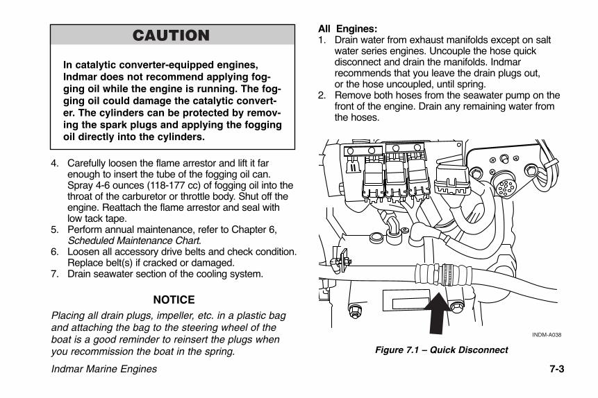
In catalytic converter-equipped engines,
Indmar does not recommend applying fog-
ging oil while the engine is running. The fog-
ging oil could damage the catalytic convert-
er. The cylinders can be protected by remov-
ing the spark plugs and applying the fogging
oil directly into the cylinders.
4. Carefully loosen the flame arrestor and lift it farenough to insert the tube of the fogging oil can.Spray 4-6 ounces (118-177 cc) of fogging oil into thethroat of the carburetor or throttle body. Shut off theengine. Reattach the flame arrestor and seal withlow tack tape.
5. Perform annual maintenance, refer to Chapter 6,Scheduled Maintenance Chart.
6. Loosen all accessory drive belts and check condition.Replace belt(s) if cracked or damaged.
7. Drain seawater section of the cooling system.
NOTICE
Placing all drain plugs, impeller, etc. in a plastic bagand attaching the bag to the steering wheel of theboat is a good reminder to reinsert the plugs whenyou recommission the boat in the spring.
All Engines:1. Drain water from exhaust manifolds except on salt
water series engines. Uncouple the hose quick disconnect and drain the manifolds. Indmar recommends that you leave the drain plugs out, or the hose uncoupled, until spring.
2. Remove both hoses from the seawater pump on thefront of the engine. Drain any remaining water fromthe hoses.
Figure 7.1 – Quick Disconnect
INDM-A038
Indmar Marine Engines 7-3
OME0502-08 Body.qxd:OM0502-05 Body.qxd 5/28/08 2:07 PM Page 7-3
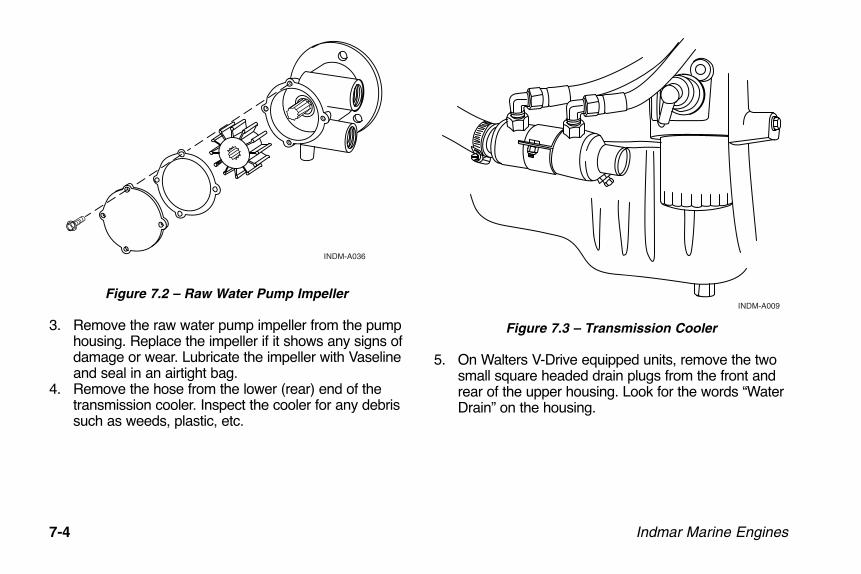
7-4 Indmar Marine Engines
Figure 7.2 – Raw Water Pump Impeller
3. Remove the raw water pump impeller from the pumphousing. Replace the impeller if it shows any signs ofdamage or wear. Lubricate the impeller with Vaselineand seal in an airtight bag.
4. Remove the hose from the lower (rear) end of thetransmission cooler. Inspect the cooler for any debrissuch as weeds, plastic, etc.
Figure 7.3 – Transmission Cooler
5. On Walters V-Drive equipped units, remove the twosmall square headed drain plugs from the front andrear of the upper housing. Look for the words “WaterDrain” on the housing.
INDM-A009
INDM-A036
OME0502-08 Body.qxd:OM0502-05 Body.qxd 5/28/08 2:07 PM Page 7-4

Indmar Marine Engines 7-5
6. On Ski-Vee equipped units, the hoses that are con-nected to the integral V-Drive cooler (1, Figure 7.4)must be removed to drain the hoses and cooler. Theanodes (2, Figure 7.4) at the back of the cooler mustbe removed and inspected. Replace if they are 50%eroded.
Figure 7.4 – Ski-Vee
Figure 7.5 – Walter V-Drive Drain Plugs
NOTICE
Placing all drain plugs, impeller, etc. in a plastic bagand attaching the bag to the steering wheel of theboat is a good reminder to reinsert the plugs whenyou recommission the boat in the spring.
WATER LINE
WATER DRAIN
WATER DRAIN
INDM-A040
INDM-A041
1
22
1
OME0502-08 Body.qxd:OM0502-05 Body.qxd 5/28/08 2:07 PM Page 7-5

7-6 Indmar Marine Engines
Raw Water Cooled Engines
NOTICE
Placing the drain plugs in a plastic bag and attachingit to the steering wheel of the boat will act as areminder to reinstall the drain plugs during recommis-sioning in spring.
1. Remove the drain plug or sensor from each side ofthe engine.
Figure 7.6 – Anti Knock Sensor
NOTICE
Some 5.7 Liter engines have a knock sensorlocated in the drain locations on both sides ofthe engine. The knock sensor and knock sen-
sor stud must be carefully removed to drain that sideof the block.
NOTICEOn the 8.1 Liter engine, removing the knock sensordoes NOT drain the block. Remove the plugs from thebrass fillings on both sides of the engine to drainwater from the block.
2. Use a short piece of stiff wire and poke around in thedrain hole to ensure that any rust or scale is brokenapart, and the engine drains completely.
3. Disconnect the large diameter hose that runs fromthe water-circulating pump to the thermostat housing.Make sure all of the water drains from the hose.
IND-A005A
1
OME0502-08 Body.qxd:OM0502-05 Body.qxd 5/28/08 2:07 PM Page 7-6
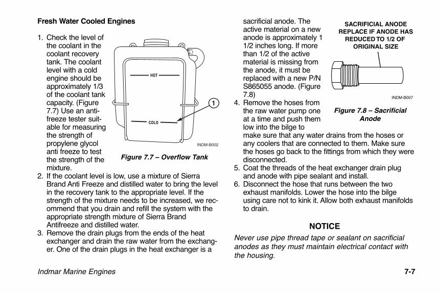
Indmar Marine Engines 7-7
Fresh Water Cooled Engines
1. Check the level ofthe coolant in thecoolant recoverytank. The coolantlevel with a coldengine should beapproximately 1/3of the coolant tankcapacity. (Figure7.7) Use an anti-freeze tester suit-able for measuringthe strength ofpropylene glycolanti freeze to testthe strength of themixture.
2. If the coolant level is low, use a mixture of SierraBrand Anti Freeze and distilled water to bring the levelin the recovery tank to the appropriate level. If thestrength of the mixture needs to be increased, we rec-ommend that you drain and refill the system with theappropriate strength mixture of Sierra BrandAntifreeze and distilled water.
3. Remove the drain plugs from the ends of the heatexchanger and drain the raw water from the exchang-er. One of the drain plugs in the heat exchanger is a
sacrificial anode. Theactive material on a newanode is approximately 11/2 inches long. If morethan 1/2 of the activematerial is missing fromthe anode, it must bereplaced with a new P/NS865055 anode. (Figure7.8)
4. Remove the hoses fromthe raw water pump oneat a time and push themlow into the bilge tomake sure that any water drains from the hoses orany coolers that are connected to them. Make surethe hoses go back to the fittings from which they weredisconnected.
5. Coat the threads of the heat exchanger drain plugand anode with pipe sealant and install.
6. Disconnect the hose that runs between the twoexhaust manifolds. Lower the hose into the bilgeusing care not to kink it. Allow both exhaust manifoldsto drain.
NOTICE
Never use pipe thread tape or sealant on sacrificialanodes as they must maintain electrical contact withthe housing.
HOT
COLD
INDM-B002
1
Figure 7.7 – Overflow Tank
SACRIFICIAL ANODEREPLACE IF ANODE HAS
REDUCED TO 1/2 OF ORIGINAL SIZE
INDM-B007
Figure 7.8 – SacrificialAnode
OME0502-08 Body.qxd:OM0502-05 Body.qxd 5/28/08 2:07 PM Page 7-7

7-8 Indmar Marine Engines
Drive Train Preparation
1. Change the transmission fluid and clean the filterscreen following the instructions in the TransmissionOwner’s Manual.
2. Remove the attaching hardware from the propellershaft coupling. Separate the flanges and coat the surfaces with Pennzoil Premium Plus Multipurposegrease.
General Power Package Preparation
1. Clean dirt, grime and grease from painted surfaces ofthe engine and drive train.
2. Touch-up painted areas of the engine and transmis-sion.
3. Lubricate throttle and shift linkages and cables withPennzoil Premium Plus Multipurpose Grease.
REACTIVATING ENGINE AFTER EXTENDED
STORAGE
Use caution when connecting the battery
cables. Improperly connecting the battery
cables or using the wrong battery type can
damage electrical components. These dam-
ages are not covered by your warranty.
1. Charge and reinstall the battery in the boat. Makesure terminals are clean and tight.
2. Coat the threads of the manifold drain plugs withpipe sealant and Install the manifold drain plugs inthe back of the exhaust manifold and/or reconnectexhaust manifold drain hoses.
3. Coat the threads of the block drains with pipe sealantand install in the engine block. EFI engines mayhave knock sensors located in the drain holes. Ifyour engine has knock sensors, they must be rein-stalled using thread sealant. Do not over tighten theknock sensor. Torque specification for the knock sen-sor stud is 14-16 lb. ft. (19 to 21.5 N•m).
4. On Walter V-Drive units, coat the threads on thedrain plugs with pipe sealant and reinstall on thefront and rear of the transmission housing.
5. Reinstall the raw water pump impeller, be sure to usea new gasket for the housing cover. Re-attach theinlet and outlet hoses to the raw water pump.
6. Reattach the large diameter hose to the water-circu-lating pump.
7. Reattach the water hose to the transmission cooler.8. On fresh water cooled models, reattach the raw
water inlet and outlet hoses.9. Install a new set of spark plugs in the engine.10. Inspect accessory drive belts and tighten to the
proper tension if necessary.11. Check condition of the distributor cap and rotor on
5.7L engines, and replace if worn, damaged or cor-roded.
OME0502-08 Body.qxd:OM0502-05 Body.qxd 5/28/08 2:07 PM Page 7-8

Indmar Marine Engines 7-9
12. If the fuel tank was drained, fill tank with fresh fuelthat does not contain alcohol.
13. Check all fluid, oil and coolant levels on engine anddrive train.
14. Check engine compartment and bilge for nesting ani-mals. Clean as necessary. Check for any damage orevidence of fluid leaks.
15. Remove tape from flame arrestor. Check alignmentbetween the output flange on the transmission andthe prop shaft flange. If the maximum feeler gaugethat can slip between the flange faces at any point is0.003" (0.08 mm), the unit is properly aligned. If athicker gauge can be inserted at any point, the enginemust be readjusted until proper alignment is obtained.
Figure 7.9 – Prop Shaft Flange Alignment
NOTICE
With the boat in the water or a hose andadapter installed, cycle the key switch ON,then OFF, for five second intervals 8-10 times
before cranking the engine to allow the fuel pump toprime the fuel lines.
16. Review boat manufacturers starting procedure.
17. Start the engine. If you experience a no-start condi-tion, do not crank the engine for more than 15 sec-onds without allowing a two minute cool-down peri-od. When the engine starts, keep a close watch onthe gauge readings. Check all of the hoses and drainplugs for leaks. Listen for abnormal noises. Run theengine long enough to reach normal operating tem-perature and re-inspect for leaks. If no leaks arefound, the boat is ready for operation.
.003"
INDM-A037
OME0502-08 Body.qxd:OM0502-05 Body.qxd 5/28/08 2:07 PM Page 7-9
7-10 Indmar Marine Engines
OME0502-08 Body.qxd:OM0502-05 Body.qxd 5/28/08 2:07 PM Page 7-10
Indmar Marine Engines 8-1
Your Indmar engine is manufactured under strict qualitycontrol standards. It is tested along with a full spectrumgas analysis. It is operating at optimum levels before it isshipped. Indmar engines have the exclusive Indmar3-year limited warranty.
Difficulties can occur. Use the following problemdiagnosis charts to help pinpoint problems. In mostcases, you will need the assistance of your Indmar deal-er to correct the cause of the problem.
Poor Gas Mileage1. Fouled spark plugs2. Plugged flame arrestor3. Poor driving habits4. Closed or partially closed choke (carbureted
engines only)5. Plugged positive crankcase ventilation system6. Black smoke at exhaust outlet shows rich gas mixture7. Excessive boat loads (weight)8. Damaged or dirty hull9. High altitude adjustment required10. Adjustment for temperature extremes required
Hard Cold Start1. Weak or discharged battery2. Choke held open (carbureted engines only)3. Loose coil or ignition wires4. Engine Flooded5. Fouled spark plugs6. Lack of fuel at carburetor (carbureted engines only)7. Battery cables loose or corroded8. Loose electrical grounds at engine9. Ignition switch problems10. Dirt or water in fuel system11. Engine needs tune-up
Poor High Speed Performance1. Fouled spark plugs, incorrect spark plug gap or heat
range2. Closed or partially closed choke (carbureted
engines only)3. Dirt or water in fuel4. Lack of fuel in carburetor (carbureted engines only)5. Restricted exhaust system6. Plugged flame arrestor
Chapter 8TROUBLESHOOTING
OME0502-08 Body.qxd:OM0502-05 Body.qxd 5/28/08 2:07 PM Page 8-1

8-2 Indmar Marine Engines
7. Insufficient air supply to engine8. Engine needs tune-up9. Damaged or incorrect propeller10. Engine needs to be adjusted for high altitude
operations11. Engine needs to be adjusted for temperature
extremes
Engine Cranks / Won’t Start1. Weak or shorted coil; no spark at plugs2. Loose engine grounds3. Lack of fuel at carburetor (carbureted engines only)4. Weak or discharged battery5. Boat Engine Safety switch not attached6. Vapor lock
Idle — Misses or Runs Rough1. Spark plugs fouled or cracked2. Spark plug or distributor wires loose or shorted3. Plugged positive crankcase ventilation system4. Engine in need of tune-up5. Engine needs to be adjusted for high altitude
operations6. Engine needs to be adjusted for temperature
extremes7. Carburetor out of adjustment (carbureted engines
only)
Hard Start Hot1. Flooding condition2. Loose electrical ground at engine3. Closed choke (carbureted engines only)4. Plugged flame arrestor5. Fouled spark plugs6. Loose coil or ignition wires7. Battery cables loose or corroded8. Weak or discharged battery 9. Vapor lock
Engine Won’t Crank1. Weak or discharged battery; loose or corroded
battery cables2. Defective neutral safety switch or adjustment needed3. Defective starter motor4. Ignition switch problems5. Hydrostatic lockup — remove spark plugs to look for
water or gasoline in cylinders6. Seized engine — turn crank pulley with socket and
ratchet
OME0502-08 Body.qxd:OM0502-05 Body.qxd 5/28/08 2:07 PM Page 8-2

Indmar Marine Engines A-1
Engine Oil All 5.7, 6.0, 6.2L (383) 15W-40 Pennzoil Marine, API Service SL/SJ/CI-4, CH-4, CG-4All 7.4L, 8.1L, 8.2L 40W Pennzoil Marine Service SL/SJ/CI-4, CH-4, CG-4
All LS7 5W30 Mobil 1
Engine Oil Filter All 5.7 and 6.0 Liter – Pennzoil PZ38.1 Liter – AC-PF454 w/o Remote Oil
8.1L w/ Remote Oil - Pennzoil PZ3
Engine Coolant (for fresh water cooled systems) Sierra brand propylene glycol
ZF Hurth Transmission (1:1 Transmission) (Ski-Vee Transmission) Pennzoil Type A Dexron II, III or Dexron/Mercon
ZF V-Drive and Reduction Gears 15W-40 Pennzoil Marine, API Service SL/SJ/CI-4, CH-4, CG-4
Walters V-Drive SAE 30 Pennzoil Motor Oil
Engine Fuel (for storage) STA-BIL fuel stabilizer
Engine Cables (for corrosion protection) Pennzoil Marine Z-M Corrosion Protectant and Lubricant
Starter Bendix Pennzoil Premium Plus Multipurpose Grease
Appendix – AMAINTENANCE COMPONENTS AND FLUIDS
OME0502-08 Body.qxd:OM0502-05 Body.qxd 5/28/08 2:07 PM Page A-1

A-2 Indmar Marine Engines
Alternator Belt All Indmar 5.7 Liter – Indmar 725018All Malibu MasterCraft 5.7L and 6.2L – Indmar 725034
LS7/6.0 serpentine – Indmar 7250288.1 Liter – Indmar 725030
Thermostat All Raw water cooled – Indmar 985009All Closed cooled except LS7/6.0L – Indmar 986034
LS7/6.0L – Indmar 986110
Spark Plugs All 5.7 and 6.2 Liter – AC Delco 41-932 Platinum6.0L – AC Delco 41-985
8.1 Liter – AC Delco 41-983LS7 – AC Delco 41-104
Surface Corrosion Protection Pennzoil Marine Z-M Corrosion Protectant and Lubricant
Engine Fogging Oil Pennzoil Marine Fogging Oil
OME0502-08 Body.qxd:OM0502-05 Body.qxd 5/28/08 2:07 PM Page A-2

Indmar Marine Engines B-1
Appendix – BENGINE SPECIFICATIONS
See page ii for engine models 5.7L Carbureted 5.7L MPI 6.2L (383) LS7 LS2/LS3/LY6 8.1L MPINumber of Cylinders V-8Displacement 350 CID (5.7L) 383 CID (6.3L) 427 CID (7.0L) 364 CID (6.0L) 496 CID (8.1L)
Bore/Stroke4.0012 x 3.480 in.
(101.63 x 88.39 mm)4.0012 x 3.8 in
(101.63 x 96.52 mm)4.125 x 4.00
(104.8 x 101.6)3.898 x 3.622 in.
(99 x 92 mm) 4.25 x 4.37 in.
(108 x 111 mm)Compression Ratio 9.4:1 9.7:1 11.0:1 10.1:1 9.1:1Compression Pressure (Note 1) Minimum 100 PSI (690 kPa)Idle RPM in Neutral (Note 2) 650 ± 50 RPMOperating Range at WOT 4400-4800 RPM 4600-5200 RPM 5200-5600 RPM 5000-5400 RPMOil Pressure at Idle 4 PSI (41 kPa) Minimum Hot 5 PSI (34 kPa) MinOil Pressure at 2000 RPM 18 PSI (124 kPa) Minimum Hot 10 PSI (69 kPa) Min
Oil Filter Pennzoil PZ3, AC-PF25AC-PF454 (on engine) Pennzoil PZ3 (remote)
Fuel Pump Pressure8 PSI Max(55.2 kPa)
60 PSI Min at Keyup (414 kPa)
Electrical System 12 Volt DC Negative (-) GroundMinimum Battery Requirements 650 cca/700 mca/120AhFiring Order 1-8-4-3-6-5-7-2 1-8-7-2-6-5-4-3Spark Plug Type AC 41-932 or 41-993 AC 41-104 AC 41-985 AC 41-983
Spark Plug Gap0.030 in.
(0.76 mm)0.060 in. (1.5 mm) 0.050 in. (1.3 mm)
Base Timing at 1000 RPM (Note 3) 10° BTDC Non AdjustableThermostat 160° F (71° C)
OME0502-08 Body.qxd:OM0502-05 Body.qxd 5/28/08 2:07 PM Page B-1

B-2 Indmar Marine Engines
Fluid Capacities 5.7L Carbureted 5.7L MPI 6.2L (383) LS7 LS2/LS3/LY6 8.1L MPICrankcase (With Filter) (Note 4) 5.5 Quarts (5.25 L) with Filter 10 Quarts (9.5 L)Closed Cooling System (Note 5) 12-14 Quarts (11.4-13.3 L) 14-16 Quarts (13.2-15.1 L)In-Line 1:1 Transmission (Note 4) 1.7 Quarts (1.6 L) Dexron 3 ATF 4.2 Quarts (4 L) 15W40In-Line Reduction Gear (Note 4) 2.12 Quarts (2 L) Pennzoil 15W40 4.2 Quarts (4 L) 15W40ZF Ski Vee Transmission (Note 4) 2.12 Quarts (2 L) Main Gearbox, 1.0 Quart (1.06 L) V-drive - Dexron 3ZF V-Drive Transmission (Note 4) 4.2 Quarts (4 L) Pennzoil 15W40Walter V-Drive 0.5 Quart (0.5 L) Pennzoil SAE 30 Motor Oil
OME0502-08 Body.qxd:OM0502-05 Body.qxd 5/28/08 2:07 PM Page B-2

Indmar Marine Engines B-3
454 Carb 502 Carb
Number of Cylinders V-8Displacement 454 CID (7.4L) 502 CID (8.2L)
Bore/Stroke 4.25 x 4 in. 4.46 x 4 in.(107.95 x 101.6 mm) (113.28 x 101.6 mm)
Compression Ratio 8.6:1 8.75:1Compression Pressure (Note 1) Minimum 100 PSI (690 kPa)Idle RPM in Neutral (Note 2) 650 ± 50 RPMOperating Range at WOT 4400-4800 RPMOil Pressure at Idle 5 PSI (34 kPa) MinimumOil Pressure at 2000 RPM 10 PSI (69 kPa) MinimumOil Filter AC-PF454/Pennzoil PZ-45Fuel Pump Pressure 8 PSI Max (55.2 kPa)Electrical System 12 Volt DC Negative (-) GroundMinimum Battery Requirements 550 cca/700 mca/120AhFiring Order 1-8-4-3-6-5-7-2Spark Plug Type MR43TSpark Plug Gap 0.045 in. (1.1 mm)Base Timing at 1000 RPM (Note 3) 10˚ Before Top Dead CenterThermostat 160° F (71° C) - No Thermostat in Jets
OME0502-08 Body.qxd:OM0502-05 Body.qxd 5/28/08 2:07 PM Page B-3

B-4 Indmar Marine Engines
Fluid Capacities 454 Carb 502 Carb
Crankcase (With Filter)(Note 4) 7 Quarts (6.62 L) With Filter (10 Quarts with Jet Pan)Closed Cooling System (Note 5) 14-16 Quarts (13.25-15.14 L)In-Line Transmission (Note 4) 2.12 Quarts (2.0 L) Dexron 3 ATFWalters V-Drive Transmission (Note 4) 2 Pints (0.95 L) 30W Motor OilHurth V-Drive Transmission (Note 4) 4.4 Quarts (4.16 L) 15W40 Motor Oil
Notes:1) Minimum recorded compression in any one cylinder should not be less than 70% of the highest recorded cylinder.2) Measured using an accurate shop tachometer at normal operating temperature. Idle RPM on EFI models is not
adjustable.3) Timing must be set using special procedures indicated in the appropriate service manual. Timing cannot be set
using conventional methods. Special tool(s) required.4) Always use dipstick to determine exact quantity of oil required. Do not fill above “FULL” mark.5) Do not over fill. Correct level is at the “Full Cold” mark on the coolant recovery bottle when coolant is cold.
OME0502-08 Body.qxd:OM0502-05 Body.qxd 5/28/08 2:07 PM Page B-4
Indmar Marine Engines C-1
1. Warranty. Indmar Products Co., Inc., 5400 Old Millington Road, Millington, Tennessee 38053 (“Indmar”), warrants that its marinepropulsion engine and the parts related thereto (collectively, “Product”) are free from material defects in material and workmanshipunder normal use and service during the applicable warranty period as set forth herein.
2. Coverage. Indmar shall replace or repair any defect in material or workmanship relating to the Product under the terms and con-ditions of this Limited Product Warranty. Components or parts of the Product that Indmar determines in its sole discretion to be “worn-out” from use are specifically excluded from this Limited Product Warranty. If a Product or defective part thereof is, upon examina-tion by Indmar, determined by Indmar to be defective, Indmar shall repair, or at its sole option, provide either a new or rebuilt replace-ment of equivalent quality. Indmar shall have the sole discretion to determine whether the replacement, if provided, shall be a newor rebuilt replacement. Indmar’s sole obligation under this Limited Product Warranty is limited only to the foregoing obligations asstated herein.
3. Customer. This Limited Product Warranty is extended only to the original retail purchaser of a boat or the original lessor, in thecase of a leased boat, in which a Product has been installed pursuant to Indmar’s approval or authority (“Customer”). If the boat issold or traded prior to the end of the applicable warranty period set forth herein, the remainder of the applicable warranty period istransferable to the new owner or new lessor (also referred herein as “Customer”) provided that all of the requirements for a valid trans-fer as set forth in this Limited Product Warranty are satisfied. No transfer of any rights by any Customer shall be deemed valid oreffective unless and until approved in writing by Indmar. Warranties of any nature to any person other than those described hereinare specifically excluded.
4. Excluded Items. In addition to, and without in any way limiting, any exclusion set forth elsewhere in this Limited ProductWarranty, this Limited Product Warranty shall not apply to the following items:
(a) Shop supplies used in performing work pursuant to this Limited Product Warranty, including, but not limited to, rags, sealantsand lubricants.
Appendix – CINDMAR LIMITED PRODUCT WARRANTY
OME0502-08 Body.qxd:OM0502-05 Body.qxd 5/28/08 2:07 PM Page C-1

C-2 Indmar Marine Engines
(b) Incidental and consequential damages, including, but not limited to, storage charges, telephone or rental charges of any type,inconvenience or loss of time or income.
(c) Minor adjustments and tune-ups, including, but not limited to, checking, cleaning or adjusting spark plugs, carburetor setting,filters, belts, controls and checking lubrication.
(d) Water pump impellers, water hoses, cooling system anodes, or any component determined solely by Indmar to be damagedfrom the failure of any of such items.
(e) Product failure as determined solely by Indmar to be caused by neglect, lack of maintenance, accident, abnormal operation,improper installation, improper preparation, improper winterization, improper dealer set-up, improper service or normal wearand tear.
(f) Haul-out, launch, and towing charges.
(g) Cost and expense incurred that relate to the removal and/or replacement of boat partitions or material due to boat design fornecessary access to the Product.
(h) Transportation charges and travel time incurred by Indmar to fulfill any of its obligations pursuant to this Limited ProductWarranty.
(i) Service or work to the Product as requested by the Customer that is as determined solely by Indmar to be beyond the scopeof this Limited Product Warranty.
(j) Use of parts other than Indmar parts (or parts authorized by Indmar) and the use of labor other than Indmar labor (or laborauthorized by Indmar) when making repairs or providing a replacement under this Limited Product Warranty.
(k) Oil, lubricants or fluids used for the normal maintenance of the Product.
(l) Defects to the Product as determined solely by Indmar to be caused by or due to participation in or preparing for racing orother competitive activity.
(m) Defects to the starter motor, armatures or field coil assembly of the Product as determined solely by Indmar to be caused byexcessive cranking, condensation or submersion.
(n) Defects to the Product as determined solely by Indmar to be caused by water entering the Product via the intake or exhaustsystem or submersion.
OME0502-08 Body.qxd:OM0502-05 Body.qxd 5/28/08 2:07 PM Page C-2

Indmar Marine Engines C-3
(o) Defects to the Product as determined solely by Indmar to be caused by the use of fuels and lubricants that are not suitablefor use with or on the Product or its fuel system components that was damaged or rendered inoperable from stale gasoline.
(p) Defects to the Product as determined solely by Indmar to be caused by the lack of cooling water resulting from the motorbeing started out of water or foreign materials blocking intake passages.
(q) Defects to the Product as determined solely by Indmar to be caused by servicing errors made by the Customer or by anyservicing dealer/mechanic not approved or authorized by Indmar.
(r) Product warranty claims that Indmar in its sole opinion determines are not due or traceable to material defects in material orworkmanship of the Product.
5. Inspection and Testing of Product. Certain parts of the Product may be tested upon receipt by Indmar. Such parts found tobe free of defects will be returned to the dealer and no credit will be issued. Indmar reserves the right to retrieve run time/run condi-tion data from a Product’s Electric Control Module prior to granting any warranty coverage on the Product under this Limited ProductWarranty.
6. Warranty Period. Warranty coverage shall be provided only for the periods of time hereinafter set forth:(a) For Product installed in boats manufactured by a manufacturer approved by Indmar (OEM):
(i) A period of thirty-six (36) months commencing from the date of purchase or the date of commencement of the Productuse, whichever sooner occurs, in the case of non-commercial use;
(ii) A period of thirty-six (36) months commencing from the lease date if the lease is for private use and is for a time periodof not less than two (2) years; or
(iii) A period of three (3) months commencing from the date of purchase or lease inception or the date of commencement ofthe Product use, whichever sooner occurs, in the case of commercial use.
(b) For repowers (defined as engines purchased for replacement) or the installation of the Product in boats by a manufacturernot approved or authorized by Indmar:
(i) A period of twelve (12) months commencing from the date of purchase or the date of commencement of the Product use,whichever sooner occurs, in the case of non-commercial use; or
(ii) A period of three (3) months commencing from the date of purchase or the date of commencement of the Product use,whichever sooner occurs, in the case of commercial use.
OME0502-08 Body.qxd:OM0502-05 Body.qxd 5/28/08 2:07 PM Page C-3
C-4 Indmar Marine Engines
In the event that more than one warranty time period may be applicable to a particular Product pursuant to this Section 6, the short-est period of time shall apply and shall be the only warranty time period allowed for that Product.
The repair or replacement of parts or the performance of service under this Limited Product Warranty does not extend the applicableperiod of this warranty beyond its original expiration date as set forth herein.
7. Procedure. Within 10 days from the date of purchase by the original retail purchaser of the Product or the beginning date oflease period, the Customer shall either (i) complete and mail the Indmar Warranty Registration Card to Indmar; or (ii) register theProduct online by visiting www.indmar.us. In addition to other requirements set forth herein, no warranty claim will be honored with-out Indmar’s prior receipt of the Indmar Warranty Registration Card or the successful online registration of the Product. In the caseof a leased boat, a copy of the lease contract showing the length of the lease must be delivered to Indmar. In the case of a warran-ty transfer to a subsequent owner or lessor, the new owner/lessor’s information along with a check for $200.00 made payable to“Indmar Warranty Transfer” must be sent to Indmar within 10 days of the transfer. No transfer shall be effective or valid unless anduntil approved by Indmar in its sole discretion. In the case of a warranty transfer relating to a leased boat, a copy of the lease contractshowing the length of the lease must also be submitted to Indmar along with the $200.00 check. For warranty claims to be assertedhereunder, the Product or defective part thereof, together with a written notice of itemized defects must be returned to the retailer fromwhom the Product was purchased or to any other convenient Indmar authorized dealer. To obtain the location of an authorized Indmardealer or service center in your area, write to Indmar requesting such information or visit www.indmar.com. In the event that thelocal authorized Indmar dealer is unable to remedy a warranted defect in the Product, the Product or defective part thereof, togetherwith a written notice of itemized defects, must be delivered to Indmar at 5400 Old Millington Road, Millington, Tennessee 38053 withany and all freight and insurance charges prepaid. All insurance and freight charges and return charges incurred by Indmar for deliv-ery of the Product (or its new or rebuilt replacement) to the retail purchaser or lessor shall be paid by such purchaser or lessor. TheCustomer shall be solely responsible for any and all labor expenses related to the repair or replacement of a Product pursuant to thisLimited Product Warranty that exceed the specified services rates of Indmar in effect at the date of purchase or lease. A schedule ofservice rates of Indmar may be obtained from any authorized Indmar dealer.
8. Trade Accessories. Indmar makes no warranty of any character with respect to any and all trade accessories not manufactured by Indmar.
9. Voiding the Warranty. In addition to any requirement set forth in this Limited Product Warranty not being met or satisfied, thisLimited Product Warranty shall become void and shall not apply under the following conditions or circumstances:
(a) When the Product or any part thereof is subject to accident, alternation, modifications, abuse, misuse, neglect or impropermaintenance and Indmar in its sole discretion determines the same;
OME0502-08 Body.qxd:OM0502-05 Body.qxd 5/28/08 2:07 PM Page C-4

Indmar Marine Engines C-5
(b) When the Product is serviced by any individual or entity not authorized or approved by Indmar; or
(c) When damage to the Product results from cases not arising from defects in material and/or workmanship and Indmar in itssole discretion determines the same.
10. Notices. Any notice to Indmar set forth pursuant to this Limited Product Warranty shall be delivered to the following address:
Indmar Products Co., Inc.5400 Old Millington RoadMillington, Tennessee 38053
THE WARRANTY STATED ABOVE IS A LIMITED WARRANTY AND IT IS THE ONLY WARRANTY MADE BY INDMAR. IND-MAR DOES NOT MAKE ANY OTHER WARRANTIES EXPRESS OR IMPLIED. THERE ARE EXPRESSLY EXCLUDED ALL WARRANTIES OF MERCHANTABILITY AND FITNESS FOR A PARTICULAR PURPOSE. INDMAR SHALL HAVE NO LIABILITY WITH RESPECT TO ITS OBLIGATIONS UNDER THIS LIMITED WARRANTY OR OTHERWISE FOR CON-SEQUENTIAL, EXEMPLARY, INCIDENTAL OR PUNITIVE DAMAGES EVEN IF IT HAS BEEN ADVISED OF THE POSSIBILITYOF SUCH DAMAGES. THE STATED EXPRESS LIMITED WARRANTY IS IN LIEU OF ALL LIABILITIES OR OBLIGATIONS OFINDMAR FOR DAMAGES ARISING OUT OF OR IN CONNECTION WITH THE DEVELOPMENT, DELIVERY, USE OR PER-FORMANCE OF THE PRODUCT. IN ANY EVENT, THE LIABILITY OF INDMAR FOR ANY REASON AND UPON ANY CAUSEOF ACTION WHATSOEVER SHALL BE LIMITED TO THE AMOUNT THEN PREVIOUSLY PAID FOR THE PRODUCT BY THE CUSTOMER.
INDMAR DOES NOT AUTHORIZE ANY PERSON, EMPLOYEE, AGENT, REPRESENTATIVE OR ENTITY TO ALTER ANY OF THE TERMS AND CONDITIONS OF THIS LIMITED PRODUCT WARRANTY OR CREATE ANY OTHER OBLIGATION RELATING TO THE PRODUCT. THIS WARRANTY GIVES YOU SPECIFIC LEGAL RIGHTS, AND YOU MAY ALSO HAVEOTHER RIGHTS WHICH MAY VARY FROM STATE TO STATE.
NOTICE TO CALIFORNIA CUSTOMERS: CALIFORNIA CUSTOMERS MUST DIRECTLY NOTIFY INDMAR IN WRITING IF THEPRODUCT DOES NOT CONFORM TO APPLICABLE WARRANTIES AND (A) THE NON-CONFORMITY IS LIKELY TO CAUSEDEATH OR SERIOUS BODILY INJURY AND HAS BEEN SUBJECT TO REPAIR TWO (2) OR MORE TIMES, AND/OR (B) THE NON-CONFORMITY HAS BEEN SUBJECT TO REPAIR FOUR (4) OR MORE TIMES. CALIFORNIA CUSTOMERS AREHEREBY NOTIFIED TO THE FOLLOWING PROVISIONS OF CALIFORNIA LAW: CAL. CIVIL CODE § 1793.22 AND CAL. CIVILCODE § 1793.2(d). COMPLETE COPIES OF THESE CODE SECTIONS ARE AVAILABLE UPON REQUEST.
OME0502-08 Body.qxd:OM0502-05 Body.qxd 5/28/08 2:07 PM Page C-5

C-6 Indmar Marine Engines
OME0502-08 Body.qxd:OM0502-05 Body.qxd 5/28/08 2:07 PM Page C-6

PROPOSITION 65
The engine exhaust from this product contains chemicals known to the State of California to cause cancer, birthdefects or other reproductive harm.
WARNING
Date of Purchase:______________________ Owner Name: _____________________________________________
Address: __________________________________________________ City: ________________________________
State/Province: ___________________________ Zip/Postal Code:____________ Country: ____________________
Engine Serial Number: _____________________________ Transmission Serial Number: _______________________
10-20 Hour ServiceDate:___________ Hours:____________By:_______________________________
Every 50 (25) Hour ServiceDate:___________ Hours:____________By:_______________________________
Date:___________ Hours:____________By:_______________________________
Date:___________ Hours:____________By:_______________________________
Date:___________ Hours:____________By:_______________________________
Date:___________ Hours:____________By:_______________________________
Date:___________ Hours:____________By:_______________________________
Date:___________ Hours:____________By:_______________________________
Date:___________ Hours:____________By:_______________________________
Every 100 Hour ServiceDate:___________ Hours:____________By:_______________________________
Date:___________ Hours:____________By:_______________________________
Date:___________ Hours:____________By:_______________________________
Date:___________ Hours:____________By:_______________________________
Date:___________ Hours:____________By:_______________________________
Date:___________ Hours:____________By:_______________________________
Date:___________ Hours:____________By:_______________________________
Date:___________ Hours:____________By:_______________________________
Date:___________ Hours:____________By:_______________________________
Every 300 Hour/Annual ServiceDate:___________ Hours:____________By:_______________________________
Date:___________ Hours:____________By:_______________________________
Date:___________ Hours:____________By:_______________________________
Date:___________ Hours:____________By:_______________________________
Date:___________ Hours:____________By:_______________________________
Date:___________ Hours:____________By:_______________________________
Every 2 Year ServiceDate:___________ Hours:____________By:_______________________________
Date:___________ Hours:____________By:_______________________________
Date:___________ Hours:____________By:_______________________________
OME0502-08 CoverC.qxp:OM0502-05 Cover.qxd 5/20/08 12:56 PM Page 2

Operator’s ManualPart No. OME0502-09 Printed in U.S.A.
The first production inboard equipped with catalytic converters.
Ken Cook Co.
5400 Old Millington Road Millington, TN 38053
www.indmar.com
OME0502-08 CoverC.qxp:OM0502-05 Cover.qxd 5/20/08 12:56 PM Page 1