omc stringer sterndrive tilt system · pdf fileomc stringer sterndrive tilt system...
TRANSCRIPT

OMC STRINGER STERNDRIVE TILT SYSTEM INTRODUCTION: The purpose of this guide is to help the owners of OMC Stringer sterndrives built from 1963 to 1984 better
understand the theory of operation and repair of the standard equipment, electro-mechanical power tilt
system common to all of these OMC-built Stringer sterndrives.
The power tilt system employed on OMC Stringer drives serves two primary purposes:
• 1.) The OMC Stringer tilt system provides an unusually quick-response (lock-to-lock in under 4
seconds), power-operated, 75-degree tilt or lifting of the external sterndrive leg. The range of
lift is typically 25 percent greater than most competitive sterndrives, whose range of motion is
limited by their U-joint coupling. This lift feature is useful for beaching or trailering, and some
owners have reportedly replaced damaged props with the boat in the water.
• 2.) The OMC Stringer tilt system also serves to provide a specially designed mechanical clutch
to absorb the shock of hitting underwater obstructions while underway. The mechanical clutch
also provides an auto-locking (which slips away at between 130 to 160 ft-lbs of torque) feature
that holds down the vertical drive and prevents the drive from “self-lifting” when under reverse
thrust. The mechanical design also has another benefit: when trailering with the drive lifted, the
mechanical clutch is robust and reliable enough to hold the entire sterndrive without the
requiring the assistance of an external accessory support rod.
It is also important to point out what the OMC Stringer Power Tilt system is NOT designed to accomplish.
On other competitive U-Joint driven sterndrives the Tilt and Trim functions are typically combined and are
hydraulically driven with rams used to both lift the unit and provide a few degrees of thrust angle trim.
While this combined method works well on U-Joint driven sterndrives, USING THE OMC STRINGER TILT
FOR THRUST TRIMMING will result in premature wear of the OMC Stringer ball-gears. The tilt
should always be operated in the fully DOWN position under power on all OMC Stringers. The power tilt
can be partially raised (with engine running) underway in shallow areas and ONLY for limited a time. If
this precaution IS NOT observed premature ball gear replacement will be required.
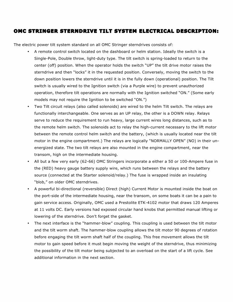
OMC STRINGER STERNDRIVE TILT SYSTEM ELECTRICAL DESCRIPTION: The electric power tilt system standard on all OMC Stringer sterndrives consists of:
• A remote control switch located on the dashboard or helm station. Ideally the switch is a
Single-Pole, Double throw, light-duty type. The tilt switch is spring-loaded to return to the
center (off) position. When the operator holds the switch “UP” the tilt drive motor raises the
sterndrive and then “locks” it in the requested position. Conversely, moving the switch to the
down position lowers the sterndrive until it is in the fully down (operational) position. The Tilt
switch is usually wired to the Ignition switch (via a Purple wire) to prevent unauthorized
operation, therefore tilt operations are normally with the Ignition switched “ON.” (Some early
models may not require the Ignition to be switched “ON.”)
• Two Tilt circuit relays (also called solenoids) are wired to the helm Tilt switch. The relays are
functionally interchangeable. One serves as an UP relay, the other is a DOWN relay. Relays
serve to reduce the requirement to run heavy, large current wires long distances, such as to
the remote helm switch. The solenoids act to relay the high-current necessary to the lift motor
between the remote control helm switch and the battery, (which is usually located near the tilt
motor in the engine compartment.) The relays are logically “NORMALLY OPEN” (NO) in their un-
energized state. The two tilt relays are also mounted in the engine compartment, near the
transom, high on the intermediate housing.
• All but a few very early (62-66) OMC Stringers incorporate a either a 50 or 100-Ampere fuse in
the (RED) heavy gauge battery supply wire, which runs between the relays and the battery
source (connected at the Starter solenoid/relay.) The fuse is wrapped inside an insulating
“blob,” on older OMC sterndrives.
• A powerful bi-directional (reversible) Direct (high) Current Motor is mounted inside the boat on
the port-side of the intermediate housing, near the transom, on some boats it can be a pain to
gain service access. Originally, OMC used a Prestolite ETK-4102 motor that draws 120 Amperes
at 11 volts DC. Early versions had exposed circular hand knobs that permitted manual lifting or
lowering of the sterndrive. Don’t forget the gasket.
• The next interface is the “hammer-blow” coupling. This coupling is used between the tilt motor
and the tilt worm shaft. The hammer-blow coupling allows the tilt motor 90 degrees of rotation
before engaging the tilt worm shaft half of the coupling. This free movement allows the tilt
motor to gain speed before it must begin moving the weight of the sterndrive, thus minimizing
the possibility of the tilt motor being subjected to an overload on the start of a lift cycle. See
additional information in the next section.

OMC STRINGER TILT SYSTEM MECHANICAL DESCRIPTION: The mechanical power tilt system standard on all OMC Stringer sterndrives is an integral part of the
intermediate housing. All tilt mechanism service can be performed without removing the intermediate
housing from the boat. The power tilt system mechanical section consists of:
• The tilt motor-driven shaft, worm gear and bearings connect to the tilt drive motor via the
hammer-blow coupling. You can visualize these running North-South inline with the boat keel,
located on the port side of the intermediate housing. (The space require to accommodate this
mechanism is the reason the rubber transom seal aperture ring is offset to port from the boat
centerline.) Note: The hammer-blow coupling is designed as a “weak-link,” to prevent damage
to more expensive parts. The hammer-blow coupler is serviced from inside the boat after
removal of the tilt drive motor. All the remaining components are accessed from outside the
boat.
• The tilt clutch worm wheel ring gear. This circular ring gear transmits movement from the tilt
worm shaft to the concentric tilt clutch pack. The ring gear sits just inside the distinctive, 4-bolt
circular tilt clutch cover, visible from outside the boat, on the port side of the external
intermediate housing.
• Circular “Belleville” springs and the clutch disc pack ride on the tilt clutch shaft, inside the worm
wheel ring gear. This shaft is on an East-West line, 90-degrees from the motor-driven worm
shaft. These items are contained within the circular clutch housing an integral part of the
intermediate housing.
• The tilt drive shaft drives an external (outside the clutch housing) spur gear. This spur gear
meshes with the quadrant tilt gear.
• The quadrant gear is bolted directly to the sterndrive upper gear case. Any movement of the tilt
drive spur gear causes the quadrant gear to lift or lower the sterndrive leg.
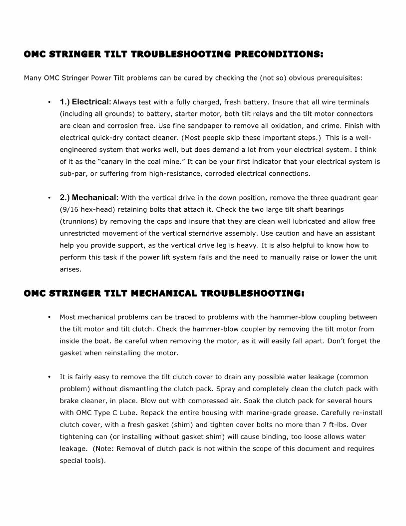
OMC STRINGER TILT TROUBLESHOOTING PRECONDITIONS: Many OMC Stringer Power Tilt problems can be cured by checking the (not so) obvious prerequisites:
• 1.) Electrical: Always test with a fully charged, fresh battery. Insure that all wire terminals
(including all grounds) to battery, starter motor, both tilt relays and the tilt motor connectors
are clean and corrosion free. Use fine sandpaper to remove all oxidation, and crime. Finish with
electrical quick-dry contact cleaner. (Most people skip these important steps.) This is a well-
engineered system that works well, but does demand a lot from your electrical system. I think
of it as the “canary in the coal mine.” It can be your first indicator that your electrical system is
sub-par, or suffering from high-resistance, corroded electrical connections.
• 2.) Mechanical: With the vertical drive in the down position, remove the three quadrant gear
(9/16 hex-head) retaining bolts that attach it. Check the two large tilt shaft bearings
(trunnions) by removing the caps and insure that they are clean well lubricated and allow free
unrestricted movement of the vertical sterndrive assembly. Use caution and have an assistant
help you provide support, as the vertical drive leg is heavy. It is also helpful to know how to
perform this task if the power lift system fails and the need to manually raise or lower the unit
arises.
OMC STRINGER TILT MECHANICAL TROUBLESHOOTING:
• Most mechanical problems can be traced to problems with the hammer-blow coupling between
the tilt motor and tilt clutch. Check the hammer-blow coupler by removing the tilt motor from
inside the boat. Be careful when removing the motor, as it will easily fall apart. Don’t forget the
gasket when reinstalling the motor.
• It is fairly easy to remove the tilt clutch cover to drain any possible water leakage (common
problem) without dismantling the clutch pack. Spray and completely clean the clutch pack with
brake cleaner, in place. Blow out with compressed air. Soak the clutch pack for several hours
with OMC Type C Lube. Repack the entire housing with marine-grade grease. Carefully re-install
clutch cover, with a fresh gasket (shim) and tighten cover bolts no more than 7 ft-lbs. Over
tightening can (or installing without gasket shim) will cause binding, too loose allows water
leakage. (Note: Removal of clutch pack is not within the scope of this document and requires
special tools).

OMC STRINGER STERNDRIVE POWER TILT ELECTRICAL LOGIC CHART 1. Check for Fully Charged BATTERY?
• If not OK, then charge or replace battery and cables
• Also, clean all terminals (including grounds) and connectors on tilt relays, tilt motor
• If Ok, go to next step
2. Check if TILT MOTOR Runs, then Stalls or Hesitates?
• If motor stalls or hesitates, then check for mechanical binding of tilt clutch or tilt trunion
bearings, (Lifting is more current demanding, than Lowering.)
• If tilt motor doesn’t operate properly in both directions, go to next step
3. Check for 12 VDC at TILT MOTOR terminals when switching both TILT directions at helm • If OK, then remove, repair/replace tilt motor carefully as it may come apart in pieces
• If no 12V at connector, go to next step
4. If Only One Direction (circuit) Is Faulty, Then Go to Defective circuit, following steps 5-9. • Check that both UP and DOWN circuit paths operate identically
• BIA wiring color code: UP = BLUE SKY, DOWN = GREEN GRASS
• Note: Relays (solenoids) are functionally interchangeable for troubleshooting
• If both UP & DOWN circuits test faulty in this step, run steps 5-9 twice, once for each circuit. 5. Check for 12 VDC at TILT RELAY POWER INPUT terminals (large red wires)
• If No 12 V, then check circuit back to battery (+) terminal
• Check 100 Amp fuse inside “blob” near starter relay: (Disconnect wire at both ends, use Ohm
Meter or continuity tester to verify “open” or “blown” fuse.)
• If OK, go to next step 6. Check for 12 VDC at TILT SWITCH INPUT terminal (purple wire)
• If No 12 V, then check circuit back to Ignition Switch ON terminal
• If No 12 V check ignition switch, fuse, trace (+) source to battery
• If OK, go to next 7. Check for 12 VDC at TILT SWITCH OUTPUT terminal(s), UP- blue / DOWN - green
• If No 12 V, then replace switch
• If OK, go to next 8. Check for 12 VDC at TILT RELAY COIL INPUT (small), UP- blue / DOWN - green
• If no 12 V, check wiring from tilt switch to relays
• If OK, go to next
9. Check for 12 VDC at TILT RELAY POWER OUTPUT (large), UP- blue / DOWN - green • If No 12 V, replace relay(s)
• If OK, check wiring to tilt motor connector
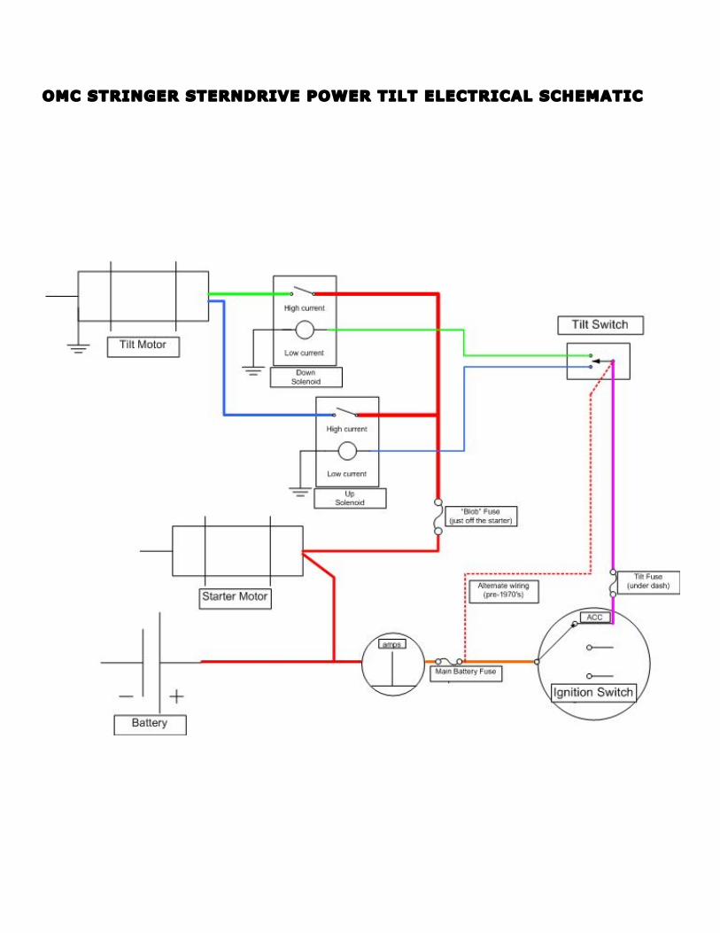
OMC STRINGER STERNDRIVE POWER TILT ELECTRICAL SCHEMATIC
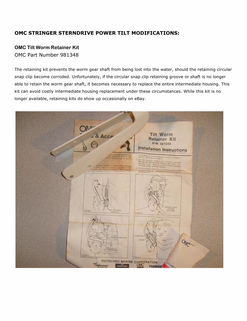
OMC STRINGER STERNDRIVE POWER TILT MODIFICATIONS:
OMC Tilt Worm Retainer Kit
OMC Part Number 981348 The retaining kit prevents the worm gear shaft from being lost into the water, should the retaining circular
snap clip become corroded. Unfortunately, if the circular snap clip retaining groove or shaft is no longer
able to retain the worm gear shaft, it becomes necessary to replace the entire intermediate housing. This
kit can avoid costly intermediate housing replacement under these circumstances. While this kit is no
longer available, retaining kits do show up occasionally on eBay.
OMC STRINGER STERNDRIVE POWER TILT MODIFICATIONS (cont.):
Power Tilt Clutch Oil Filler Plug – Grease Fitting Addition
• Remove Power Tilt Clutch Cover
• Remove any watery grease and spray clean assembled clutch pack with brake cleaner
• Blow dry with compressed air
• Soak clutch pack in OMC Type C lubricant for 30 min and then drain
• Repack assembled clutch pack with marine bearing grease
• Remove the Power Tilt Clutch Oil Fill Plug from Tilt Clutch Cover
• Drill hole and tap hole threads for 1/8-inch NPT in Screw
• Install Stainless Steel (1/8 NPT) Grease Nipple (Zerk Fitting)
• Replace the Power Tilt Clutch Fill Plug into Tilt Clutch Cover
• Tighten Cover screws to 7 ft-lbs torque
• Use a grease gun to continue pressure filling tilt clutch housing
• Use grease gun monthly but sparingly to displace water from tilt clutch housing
This inexpensive modification prevents water from getting into the power tilt clutch and motor.
It also prevents corrosion, and lubricates the tilt clutch better than the factory recommended
Type A OMC lubricant. It follows the same principles used with marine trailer wheel bearing
protectors. Use caution not to over pressure clutch housing when using grease gun.
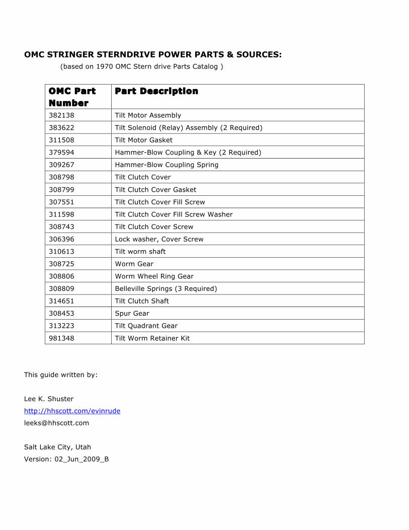
OMC STRINGER STERNDRIVE POWER PARTS & SOURCES: (based on 1970 OMC Stern drive Parts Catalog )
OMC Part Number
Part Description
382138 Tilt Motor Assembly
383622 Tilt Solenoid (Relay) Assembly (2 Required)
311508 Tilt Motor Gasket
379594 Hammer-Blow Coupling & Key (2 Required)
309267 Hammer-Blow Coupling Spring
308798 Tilt Clutch Cover
308799 Tilt Clutch Cover Gasket
307551 Tilt Clutch Cover Fill Screw
311598 Tilt Clutch Cover Fill Screw Washer
308743 Tilt Clutch Cover Screw
306396 Lock washer, Cover Screw
310613 Tilt worm shaft
308725 Worm Gear
308806 Worm Wheel Ring Gear
308809 Belleville Springs (3 Required)
314651 Tilt Clutch Shaft
308453 Spur Gear
313223 Tilt Quadrant Gear
981348 Tilt Worm Retainer Kit
This guide written by:
Lee K. Shuster
http://hhscott.com/evinrude
Salt Lake City, Utah
Version: 02_Jun_2009_B