om-228 921g processes - red-d-arc 5-20 operator manual.pdf · om-228 921g 2009−02 processes...
TRANSCRIPT

OM-228 921G 2009−02
Processes
Description
Air Carbon Arc (CAC-A) Cuttingand Gouging
Stick (SMAW) Welding
Engine Driven Welding Generator
TIG (GTAW) Welding
MIG (GMAW) Welding
Flux Cored (FCAW) Welding
File: Engine Drive


TABLE OF CONTENTS
SECTION 1 − SAFETY PRECAUTIONS − READ BEFORE USING 1. . . . . . . . . . . . . . . . . . . . . . . . . . . . . . . . . . 1-1. Symbol Usage 1. . . . . . . . . . . . . . . . . . . . . . . . . . . . . . . . . . . . . . . . . . . . . . . . . . . . . . . . . . . . . . . . . . . . . . . . 1-2. Arc Welding Hazards 1. . . . . . . . . . . . . . . . . . . . . . . . . . . . . . . . . . . . . . . . . . . . . . . . . . . . . . . . . . . . . . . . . . 1-3. Engine Hazards 3. . . . . . . . . . . . . . . . . . . . . . . . . . . . . . . . . . . . . . . . . . . . . . . . . . . . . . . . . . . . . . . . . . . . . . 1-4. Hydraulic Hazards 3. . . . . . . . . . . . . . . . . . . . . . . . . . . . . . . . . . . . . . . . . . . . . . . . . . . . . . . . . . . . . . . . . . . . 1-5. Compressed Air Hazards 4. . . . . . . . . . . . . . . . . . . . . . . . . . . . . . . . . . . . . . . . . . . . . . . . . . . . . . . . . . . . . . . 1-6. Additional Symbols For Installation, Operation, And Maintenance 5. . . . . . . . . . . . . . . . . . . . . . . . . . . . . 1-7. California Proposition 65 Warnings 6. . . . . . . . . . . . . . . . . . . . . . . . . . . . . . . . . . . . . . . . . . . . . . . . . . . . . . . 1-8. Principal Safety Standards 6. . . . . . . . . . . . . . . . . . . . . . . . . . . . . . . . . . . . . . . . . . . . . . . . . . . . . . . . . . . . . 1-9. EMF Information 6. . . . . . . . . . . . . . . . . . . . . . . . . . . . . . . . . . . . . . . . . . . . . . . . . . . . . . . . . . . . . . . . . . . . . .
SECTION 2 − CONSIGNES DE SÉCURITÉ − LIRE AVANT UTILISATION 7. . . . . . . . . . . . . . . . . . . . . . . . . . . . 2-1. Signification des symboles 7. . . . . . . . . . . . . . . . . . . . . . . . . . . . . . . . . . . . . . . . . . . . . . . . . . . . . . . . . . . . . 2-2. Dangers relatifs au soudage à l’arc 7. . . . . . . . . . . . . . . . . . . . . . . . . . . . . . . . . . . . . . . . . . . . . . . . . . . . . . 2-3. Dangers existant en relation avec le moteur 9. . . . . . . . . . . . . . . . . . . . . . . . . . . . . . . . . . . . . . . . . . . . . . . 2-4. Dangers liés à l’hydraulique 10. . . . . . . . . . . . . . . . . . . . . . . . . . . . . . . . . . . . . . . . . . . . . . . . . . . . . . . . . . . . . 2-5. Dangers liés à l’air comprimé 11. . . . . . . . . . . . . . . . . . . . . . . . . . . . . . . . . . . . . . . . . . . . . . . . . . . . . . . . . . . 2-6. Dangers supplémentaires en relation avec l’installation, le fonctionnement et la maintenance 12. . . . . . 2-7. Proposition californienne 65 Avertissements 13. . . . . . . . . . . . . . . . . . . . . . . . . . . . . . . . . . . . . . . . . . . . . . . 2-8. Principales normes de sécurité 13. . . . . . . . . . . . . . . . . . . . . . . . . . . . . . . . . . . . . . . . . . . . . . . . . . . . . . . . . . 2-9. Information EMF 14. . . . . . . . . . . . . . . . . . . . . . . . . . . . . . . . . . . . . . . . . . . . . . . . . . . . . . . . . . . . . . . . . . . . . .
SECTION 3 − DEFINITIONS 15. . . . . . . . . . . . . . . . . . . . . . . . . . . . . . . . . . . . . . . . . . . . . . . . . . . . . . . . . . . . . . . . . . . 3-1. Symbols And Definitions 15. . . . . . . . . . . . . . . . . . . . . . . . . . . . . . . . . . . . . . . . . . . . . . . . . . . . . . . . . . . . . . .
SECTION 4 − SPECIFICATIONS 16. . . . . . . . . . . . . . . . . . . . . . . . . . . . . . . . . . . . . . . . . . . . . . . . . . . . . . . . . . . . . . . . 4-1. Weld, Power, And Engine Specifications 16. . . . . . . . . . . . . . . . . . . . . . . . . . . . . . . . . . . . . . . . . . . . . . . . . . 4-2. Dimensions, Weights, And Operating Angles 16. . . . . . . . . . . . . . . . . . . . . . . . . . . . . . . . . . . . . . . . . . . . . . 4-3. Volt-Ampere Curves 17. . . . . . . . . . . . . . . . . . . . . . . . . . . . . . . . . . . . . . . . . . . . . . . . . . . . . . . . . . . . . . . . . . . 4-4. Fuel Consumption 18. . . . . . . . . . . . . . . . . . . . . . . . . . . . . . . . . . . . . . . . . . . . . . . . . . . . . . . . . . . . . . . . . . . . . 4-5. Duty Cycle And Overheating 18. . . . . . . . . . . . . . . . . . . . . . . . . . . . . . . . . . . . . . . . . . . . . . . . . . . . . . . . . . . . 4-6. Generator Power Curve 19. . . . . . . . . . . . . . . . . . . . . . . . . . . . . . . . . . . . . . . . . . . . . . . . . . . . . . . . . . . . . . . . 4-7. Optional Three-Phase Generator Curves 20. . . . . . . . . . . . . . . . . . . . . . . . . . . . . . . . . . . . . . . . . . . . . . . . .
SECTION 5 − INSTALLATION 21. . . . . . . . . . . . . . . . . . . . . . . . . . . . . . . . . . . . . . . . . . . . . . . . . . . . . . . . . . . . . . . . . . 5-1. Installing Welding Generator 21. . . . . . . . . . . . . . . . . . . . . . . . . . . . . . . . . . . . . . . . . . . . . . . . . . . . . . . . . . . . 5-2. Mounting Welding Generator 22. . . . . . . . . . . . . . . . . . . . . . . . . . . . . . . . . . . . . . . . . . . . . . . . . . . . . . . . . . . . 5-4. Rating Label Location 23. . . . . . . . . . . . . . . . . . . . . . . . . . . . . . . . . . . . . . . . . . . . . . . . . . . . . . . . . . . . . . . . . . 5-5. Using Lifting Eye 24. . . . . . . . . . . . . . . . . . . . . . . . . . . . . . . . . . . . . . . . . . . . . . . . . . . . . . . . . . . . . . . . . . . . . . 5-6. Installing Exhaust Pipe 24. . . . . . . . . . . . . . . . . . . . . . . . . . . . . . . . . . . . . . . . . . . . . . . . . . . . . . . . . . . . . . . . . 5-7. Activating The Dry Charge Battery (If Applicable) 25. . . . . . . . . . . . . . . . . . . . . . . . . . . . . . . . . . . . . . . . . . . 5-8. Connecting The Battery 25. . . . . . . . . . . . . . . . . . . . . . . . . . . . . . . . . . . . . . . . . . . . . . . . . . . . . . . . . . . . . . . . 5-9. Engine Prestart Checks 26. . . . . . . . . . . . . . . . . . . . . . . . . . . . . . . . . . . . . . . . . . . . . . . . . . . . . . . . . . . . . . . . 5-10. Adding Coolant To Radiator 27. . . . . . . . . . . . . . . . . . . . . . . . . . . . . . . . . . . . . . . . . . . . . . . . . . . . . . . . . . . . . 5-11. Connecting To Weld Output Terminals 28. . . . . . . . . . . . . . . . . . . . . . . . . . . . . . . . . . . . . . . . . . . . . . . . . . . . 5-12. Selecting Weld Cable Sizes* 29. . . . . . . . . . . . . . . . . . . . . . . . . . . . . . . . . . . . . . . . . . . . . . . . . . . . . . . . . . . . 5-13. Connecting To Remote 14 Receptacle RC14 30. . . . . . . . . . . . . . . . . . . . . . . . . . . . . . . . . . . . . . . . . . . . . .
SECTION 6 − OPERATING WELDING GENERATOR 32. . . . . . . . . . . . . . . . . . . . . . . . . . . . . . . . . . . . . . . . . . . . . . 6-1. Front Panel Controls (See Section 6-2) 32. . . . . . . . . . . . . . . . . . . . . . . . . . . . . . . . . . . . . . . . . . . . . . . . . . . 6-2. Description Of Front Panel Controls (See Section 6-1) 33. . . . . . . . . . . . . . . . . . . . . . . . . . . . . . . . . . . . . . 6-3. Process/Contactor Control Switch 34. . . . . . . . . . . . . . . . . . . . . . . . . . . . . . . . . . . . . . . . . . . . . . . . . . . . . . . 6-4. Remote Voltage/Amperage Control 35. . . . . . . . . . . . . . . . . . . . . . . . . . . . . . . . . . . . . . . . . . . . . . . . . . . . . . 6-5. Fuel/Hour Gauge Descriptions 36. . . . . . . . . . . . . . . . . . . . . . . . . . . . . . . . . . . . . . . . . . . . . . . . . . . . . . . . . .
SECTION 7 − OPERATING AUXILIARY EQUIPMENT 37. . . . . . . . . . . . . . . . . . . . . . . . . . . . . . . . . . . . . . . . . . . . . 7-1. 120 Volt And 240 Volt Receptacles 37. . . . . . . . . . . . . . . . . . . . . . . . . . . . . . . . . . . . . . . . . . . . . . . . . . . . . . . 7-2. Connecting To Optional Three-Phase Generator (High KVA Models Only) 38. . . . . . . . . . . . . . . . . . . . . .

TABLE OF CONTENTS
SECTION 8 − MAINTENANCE & TROUBLESHOOTING 39. . . . . . . . . . . . . . . . . . . . . . . . . . . . . . . . . . . . . . . . . . . 8-1. Maintenance Label 39. . . . . . . . . . . . . . . . . . . . . . . . . . . . . . . . . . . . . . . . . . . . . . . . . . . . . . . . . . . . . . . . . . . . 8-2. Routine Maintenance 40. . . . . . . . . . . . . . . . . . . . . . . . . . . . . . . . . . . . . . . . . . . . . . . . . . . . . . . . . . . . . . . . . . 8-3. Servicing Air Cleaner 41. . . . . . . . . . . . . . . . . . . . . . . . . . . . . . . . . . . . . . . . . . . . . . . . . . . . . . . . . . . . . . . . . . 8-4. Inspecting/Cleaning Optional Spark Arrestor 42. . . . . . . . . . . . . . . . . . . . . . . . . . . . . . . . . . . . . . . . . . . . . . .
8-5. Checking Generator Brushes 42. . . . . . . . . . . . . . . . . . . . . . . . . . . . . . . . . . . . . . . . . . . . . . . . . . . . . . . . . . . 8-6. Adjusting Engine Speed 43. . . . . . . . . . . . . . . . . . . . . . . . . . . . . . . . . . . . . . . . . . . . . . . . . . . . . . . . . . . . . . . . 8-7. Servicing Fuel And Lubrication Systems 44. . . . . . . . . . . . . . . . . . . . . . . . . . . . . . . . . . . . . . . . . . . . . . . . . . 8-8. Servicing Engine Cooling System 45. . . . . . . . . . . . . . . . . . . . . . . . . . . . . . . . . . . . . . . . . . . . . . . . . . . . . . . . 8-9. Overload Protection 46. . . . . . . . . . . . . . . . . . . . . . . . . . . . . . . . . . . . . . . . . . . . . . . . . . . . . . . . . . . . . . . . . . .
8-10. Troubleshooting Tables 47. . . . . . . . . . . . . . . . . . . . . . . . . . . . . . . . . . . . . . . . . . . . . . . . . . . . . . . . . . . . . . . . SECTION 9 − ELECTRICAL DIAGRAM 50. . . . . . . . . . . . . . . . . . . . . . . . . . . . . . . . . . . . . . . . . . . . . . . . . . . . . . . . . . SECTION 10 − RUN-IN PROCEDURE 52. . . . . . . . . . . . . . . . . . . . . . . . . . . . . . . . . . . . . . . . . . . . . . . . . . . . . . . . . . .
10-1. Wetstacking 52. . . . . . . . . . . . . . . . . . . . . . . . . . . . . . . . . . . . . . . . . . . . . . . . . . . . . . . . . . . . . . . . . . . . . . . . . .
10-2. Run-In Procedure Using Load Bank 53. . . . . . . . . . . . . . . . . . . . . . . . . . . . . . . . . . . . . . . . . . . . . . . . . . . . . . 10-3. Run-In Procedure Using Resistance Grid 54. . . . . . . . . . . . . . . . . . . . . . . . . . . . . . . . . . . . . . . . . . . . . . . . .
SECTION 11 − GENERATOR POWER GUIDELINES 55. . . . . . . . . . . . . . . . . . . . . . . . . . . . . . . . . . . . . . . . . . . . . . SECTION 12 − PARTS LIST 62. . . . . . . . . . . . . . . . . . . . . . . . . . . . . . . . . . . . . . . . . . . . . . . . . . . . . . . . . . . . . . . . . . . WARRANTY
OM-228 921 Page 1
SECTION 1 − SAFETY PRECAUTIONS − READ BEFORE USINGrom_2008−08
Protect yourself and others from injury — read and follow these precautions.
1-1. Symbol Usage
DANGER! − Indicates a hazardous situation which, ifnot avoided, will result in death or serious injury. Thepossible hazards are shown in the adjoining symbolsor explained in the text.
Indicates a hazardous situation which, if not avoided,could result in death or serious injury. The possiblehazards are shown in the adjoining symbols or ex-plained in the text.
NOTICE − Indicates statements not related to personal injury.
� Indicates special instructions.
This group of symbols means Warning! Watch Out! ELECTRICSHOCK, MOVING PARTS, and HOT PARTS hazards. Consult sym-bols and related instructions below for necessary actions to avoid thehazards.
1-2. Arc Welding Hazards
The symbols shown below are used throughout this manualto call attention to and identify possible hazards. When yousee the symbol, watch out, and follow the related instructionsto avoid the hazard. The safety information given below isonly a summary of the more complete safety informationfound in the Safety Standards listed in Section 1-8. Read andfollow all Safety Standards.
Only qualified persons should install, operate, maintain, andrepair this unit.
During operation, keep everybody, especially children, away.
Touching live electrical parts can cause fatal shocks orsevere burns. The electrode and work circuit iselectrically live whenever the output is on. The input
power circuit and machine internal circuits are also live when power ison. In semiautomatic or automatic wire welding, the wire, wire reel,drive roll housing, and all metal parts touching the welding wire areelectrically live. Incorrectly installed or improperly grounded equip-ment is a hazard.
ELECTRIC SHOCK can kill.
� Do not touch live electrical parts.
� Wear dry, hole-free insulating gloves and body protection.
� Insulate yourself from work and ground using dry insulating matsor covers big enough to prevent any physical contact with the workor ground.
� Do not use AC output in damp areas, if movement is confined, or ifthere is a danger of falling.
� Use AC output ONLY if required for the welding process.
� If AC output is required, use remote output control if present onunit.
� Additional safety precautions are required when any of the follow-ing electrically hazardous conditions are present: in damplocations or while wearing wet clothing; on metal structures suchas floors, gratings, or scaffolds; when in cramped positions suchas sitting, kneeling, or lying; or when there is a high risk of unavoid-able or accidental contact with the workpiece or ground. For theseconditions, use the following equipment in order presented: 1) asemiautomatic DC constant voltage (wire) welder, 2) a DC manual(stick) welder, or 3) an AC welder with reduced open-circuit volt-age. In most situations, use of a DC, constant voltage wire welderis recommended. And, do not work alone!
� Disconnect input power or stop engine before installing orservicing this equipment. Lockout/tagout input power according toOSHA 29 CFR 1910.147 (see Safety Standards).
� Properly install and ground this equipment according to itsOwner’s Manual and national, state, and local codes.
� Always verify the supply ground — check and be sure that inputpower cord ground wire is properly connected to ground terminal indisconnect box or that cord plug is connected to a properlygrounded receptacle outlet.
� When making input connections, attach proper grounding conduc-tor first − double-check connections.
� Keep cords dry, free of oil and grease, and protected from hot metaland sparks.
� Frequently inspect input power cord for damage or bare wiring —replace cord immediately if damaged — bare wiring can kill.
� Turn off all equipment when not in use.� Do not use worn, damaged, undersized, or poorly spliced cables.� Do not drape cables over your body.� If earth grounding of the workpiece is required, ground it directly
with a separate cable.� Do not touch electrode if you are in contact with the work, ground,
or another electrode from a different machine.� Use only well-maintained equipment. Repair or replace damaged
parts at once. Maintain unit according to manual.� Do not touch electrode holders connected to two welding ma-
chines at the same time since double open-circuit voltage will bepresent.
� Wear a safety harness if working above floor level.� Keep all panels and covers securely in place.� Clamp work cable with good metal-to-metal contact to workpiece
or worktable as near the weld as practical.
� Insulate work clamp when not connected to workpiece to preventcontact with any metal object.
� Do not connect more than one electrode or work cable to anysingle weld output terminal.
SIGNIFICANT DC VOLTAGE exists in inverters after stop-ping engine.� Stop engine on inverter and discharge input capacitors according
to instructions in Maintenance Section before touching any parts.
HOT PARTS can cause severe burns.
� Do not touch hot parts bare handed.� Allow cooling period before working on equip-
ment.
� To handle hot parts, use proper tools and/or wear heavy, insu-lated welding gloves and clothing to prevent burns.
FLYING METAL or DIRT can injure eyes.
� Welding, chipping, wire brushing, and grindingcause sparks and flying metal. As welds cool,they can throw off slag.
� Wear approved safety glasses with side shields even under yourwelding helmet.
OM-228 921 Page 2
Welding produces fumes and gases. Breathing thesefumes and gases can be hazardous to your health.
FUMES AND GASES can be hazardous.
� Keep your head out of the fumes. Do not breathe the fumes.� If inside, ventilate the area and/or use local forced ventilation at the
arc to remove welding fumes and gases.� If ventilation is poor, wear an approved air-supplied respirator.� Read and understand the Material Safety Data Sheets (MSDSs)
and the manufacturer’s instructions for metals, consumables,coatings, cleaners, and degreasers.
� Work in a confined space only if it is well ventilated, or whilewearing an air-supplied respirator. Always have a trained watch-person nearby. Welding fumes and gases can displace air andlower the oxygen level causing injury or death. Be sure the breath-ing air is safe.
� Do not weld in locations near degreasing, cleaning, or spraying op-erations. The heat and rays of the arc can react with vapors to formhighly toxic and irritating gases.
� Do not weld on coated metals, such as galvanized, lead, orcadmium plated steel, unless the coating is removed from the weldarea, the area is well ventilated, and while wearing an air-suppliedrespirator. The coatings and any metals containing these elementscan give off toxic fumes if welded.
BUILDUP OF GAS can injure or kill.
� Shut off shielding gas supply when not in use.� Always ventilate confined spaces or use ap-
proved air-supplied respirator.
Arc rays from the welding process produce intensevisible and invisible (ultraviolet and infrared) rays thatcan burn eyes and skin. Sparks fly off from the weld.
ARC RAYS can burn eyes and skin.
� Wear an approved welding helmet fitted with a proper shade of filterlenses to protect your face and eyes from arc rays and sparkswhen welding or watching (see ANSI Z49.1 and Z87.1 listed inSafety Standards).
� Wear approved safety glasses with side shields under yourhelmet.
� Use protective screens or barriers to protect others from flash,glare, and sparks; warn others not to watch the arc.
� Wear protective clothing made from durable, flame-resistant mate-rial (leather, heavy cotton, or wool) and foot protection.
Welding on closed containers, such as tanks, drums,or pipes, can cause them to blow up. Sparks can fly offfrom the welding arc. The flying sparks, hot workpiece,
and hot equipment can cause fires and burns. Accidental contact ofelectrode to metal objects can cause sparks, explosion, overheating,or fire. Check and be sure the area is safe before doing any welding.
WELDING can cause fire or explosion.
� Remove all flammables within 35 ft (10.7 m) of the welding arc. Ifthis is not possible, tightly cover them with approved covers.
� Do not weld where flying sparks can strike flammable material.
� Protect yourself and others from flying sparks and hot metal.
� Be alert that welding sparks and hot materials from welding caneasily go through small cracks and openings to adjacent areas.
� Watch for fire, and keep a fire extinguisher nearby.
� Be aware that welding on a ceiling, floor, bulkhead, or partition cancause fire on the hidden side.
� Do not weld on closed containers such as tanks, drums, or pipes,unless they are properly prepared according to AWS F4.1 (seeSafety Standards).
� Do not weld where the atmosphere may contain flammable dust,gas, or liquid vapors (such as gasoline).
� Connect work cable to the work as close to the welding area aspractical to prevent welding current from traveling long, possiblyunknown paths and causing electric shock, sparks, and fire haz-ards.
� Do not use welder to thaw frozen pipes.
� Remove stick electrode from holder or cut off welding wire atcontact tip when not in use.
� Wear oil-free protective garments such as leather gloves, heavyshirt, cuffless trousers, high shoes, and a cap.
� Remove any combustibles, such as a butane lighter or matches,from your person before doing any welding.
� After completion of work, inspect area to ensure it is free of sparks,glowing embers, and flames.
� Use only correct fuses or circuit breakers. Do not oversize or by-pass them.
� Follow requirements in OSHA 1910.252 (a) (2) (iv) and NFPA 51Bfor hot work and have a fire watcher and extinguisher nearby.
NOISE can damage hearing.
Noise from some processes or equipment can dam-age hearing.
� Wear approved ear protection if noise level ishigh.
MAGNETIC FIELDS can affect ImplantedMedical Devices.
� Wearers of Pacemakers and other ImplantedMedical Devices should keep away.
� Implanted Medical Device wearers should consult their doctorand the device manufacturer before going near arc welding, spotwelding, gouging, plasma arc cutting, or induction heatingoperations.
Shielding gas cylinders contain gas under high pres-sure. If damaged, a cylinder can explode. Since gascylinders are normally part of the welding process, besure to treat them carefully.
CYLINDERS can explode if damaged.
� Protect compressed gas cylinders from excessive heat, mechani-cal shocks, physical damage, slag, open flames, sparks, and arcs.
� Install cylinders in an upright position by securing to a stationarysupport or cylinder rack to prevent falling or tipping.
� Keep cylinders away from any welding or other electrical circuits.
� Never drape a welding torch over a gas cylinder.
� Never allow a welding electrode to touch any cylinder.
� Never weld on a pressurized cylinder — explosion will result.
� Use only correct shielding gas cylinders, regulators, hoses, and fit-tings designed for the specific application; maintain them andassociated parts in good condition.
� Turn face away from valve outlet when opening cylinder valve.
� Keep protective cap in place over valve except when cylinder is inuse or connected for use.
� Use the right equipment, correct procedures, and sufficient num-ber of persons to lift and move cylinders.
� Read and follow instructions on compressed gas cylinders,associated equipment, and Compressed Gas Association (CGA)publication P-1 listed in Safety Standards.

OM-228 921 Page 3
1-3. Engine Hazards
BATTERY EXPLOSION can BLIND.
� Always wear a face shield, rubber gloves, andprotective clothing when working on a battery.
� Stop engine before disconnecting or connect-ing battery cables or servicing battery.
� Do not allow tools to cause sparks when working on a battery.
� Do not use welder to charge batteries or jump start vehicles.
� Observe correct polarity (+ and −) on batteries.
� Disconnect negative (−) cable first and connect it last.
FUEL can cause fire or explosion.
� Stop engine and let it cool off before checking oradding fuel.
� Do not add fuel while smoking or if unit is nearany sparks or open flames.
� Do not overfill tank — allow room for fuel to expand.
� Do not spill fuel. If fuel is spilled, clean up before starting engine.
� Dispose of rags in a fireproof container.
� Always keep nozzle in contact with tank when fueling.
MOVING PARTS can injure.
� Keep away from fans, belts, and rotors.� Keep all doors, panels, covers, and guards
closed and securely in place.
� Stop engine before installing or connecting unit.� Have only qualified people remove doors, panels, covers, or
guards for maintenance and troubleshooting as necessary.� To prevent accidental starting during servicing, disconnect
negative (−) battery cable from battery.� Keep hands, hair, loose clothing, and tools away from moving
parts.� Reinstall doors, panels, covers, or guards when servicing is
finished and before starting engine.� Before working on generator, remove spark plugs or injectors to
keep engine from kicking back or starting.� Block flywheel so that it will not turn while working on generator
components.
EXHAUST SPARKS can cause fire.
� Do not let engine exhaust sparks cause fire.� Use approved engine exhaust spark arrestor in
required areas — see applicable codes.
HOT PARTS can cause severe burns.
� Do not touch hot parts bare handed.� Allow cooling period before working on equip-
ment.� To handle hot parts, use proper tools and/or
wear heavy, insulated welding gloves andclothing to prevent burns.
STEAM AND HOT COOLANT can burn.
� If possible, check coolant level when engine iscold to avoid scalding.
� Always check coolant level at overflow tank, ifpresent on unit, instead of radiator (unless toldotherwise in maintenance section or enginemanual).
� If the engine is warm, checking is needed, and there is no over-flow tank, follow the next two statements.
� Wear safety glasses and gloves and put a rag over radiator cap.
� Turn cap slightly and let pressure escape slowly beforecompletely removing cap.
Using a generator indoors CAN KILLYOU IN MINUTES.
� Generator exhaust contains carbon monoxide.This is a poison you cannot see or smell.
� NEVER use inside a home or garage, EVEN IFdoors and windows are open.
� Only use OUTSIDE and far away from windows, doors, andvents.
BATTERY ACID can BURN SKIN and EYES.
� Do not tip battery.� Replace damaged battery.� Flush eyes and skin immediately with water.
ENGINE HEAT can cause fire.
� Do not locate unit on, over, or near combustiblesurfaces or flammables.
� Keep exhaust and exhaust pipes way fromflammables.
1-4. Hydraulic Hazards
HYDRAULIC EQUIPMENT can injureor kill.� Incorrect installation or operation of this unit
could result in equipment failure and personalinjury. Only qualified persons should install, op-erate, and service this unit according to itsOwner’s Manual, industry standards, and na-tional, state, and local codes.
� Do not exceed the rated output or capacity of the hydraulic pumpor any equipment in the hydraulic system. Design hydraulic sys-tem so failure of any hydraulic component will not put people orproperty at risk.
� Before working on hydraulic system, turn off and lockout/tagoutunit, release pressure, and be sure hydraulic pressure cannot beaccidentally applied.
� Do not work on hydraulic system with unit running unless you are aqualified person and following the manufacturer’s instructions.
� Do not modify or alter hydraulic pump or manufacturer-suppliedequipment. Do not disconnect, disable, or override any safetyequipment in the hydraulic system.
� Use only components/accessories approved by the manufacturer.
� Keep away from potential pinch points or crush points created byequipment connected to the hydraulic system.
� Do not work under or around any equipment that is supported onlyby hydraulic pressure. Properly support equipment by mechanicalmeans.

OM-228 921 Page 4
HYDRAULIC FLUID can injure or kill.
� Before working on hydraulic system, turn off andlockout/tagout unit, release pressure, and be surehydraulic pressure cannot be accidentally applied.
� Relieve pressure before disconnecting or con-necting hydraulic lines.
� Check hydraulic system components and all con-nections and hoses for damage, leaks, and wearbefore operating unit.
� Wear protective equipment such as safetyglasses, leather gloves, heavy shirt and trousers,high shoes, and a cap when working on hydraulicsystem.
� Use a piece of paper or cardboard to search for leaks−−never usebare hands. Do not use equipment if leaks are found.
� HYDRAULIC FLUID is FLAMMABLE−−do not work on hydraulicsnear sparks or flames; do not smoke near hydraulic fluid.
� Reinstall doors, panels, covers, or guards when servicing isfinished and before starting unit.
� If ANY fluid is injected into the skin, it must be surgically removedwithin a few hours by a doctor familiar with this type of injury or gan-grene may result.
MOVING PARTS can injure.
� Keep away from fans, belts and rotors.� Keep all doors, panels, covers, and guards
closed and securely in place.
� Keep hands, hair, loose clothing, and tools away from movingparts.
� Before working on hydraulic system, turn off and lockout/tagoutunit, release pressure, and be sure hydraulic pressure cannot beaccidentally applied.
� Have only qualified people remove guards or covers for maint-enance and troubleshooting as necessary.
� Reinstall doors, panels, covers, or guards when servicing isfinished and before starting engine.
HOT PARTS AND FLUID can cause severeburns.
� Do not touch hot parts bare handed or allow hotfluid to contact skin.
� Allow cooling period before working on equip-ment.
� To handle hot parts, use proper tools and/or wear heavy, insu-lated welding gloves and clothing to prevent burns.
READ INSTRUCTIONS.
� Read Owner’s Manual before installing, oper-ating, or servicing unit.
� Use only genuine replacement parts from themanufacturer.
� Perform maintenance and service according to the Owner’sManuals, industry standards, and national, state, and localcodes.
1-5. Compressed Air Hazards
COMPRESSED AIR EQUIPMENT caninjure or kill.
� Incorrect installation or operation of this unitcould result in equipment failure and personalinjury. Only qualified persons should install, op-erate, and service this unit according to itsOwner’s Manual, industry standards, and na-tional, state, and local codes.
� Do not exceed the rated output or capacity of the compressor orany equipment in the compressed air system. Design com-pressed air system so failure of any component will not put peopleor property at risk.
� Before working on compressed air system, turn off and lockout/tagout unit, release pressure, and be sure air pressure cannot beaccidentally applied.
� Do not work on compressed air system with unit running unlessyou are a qualified person and following the manufacturer’s in-structions.
� Do not modify or alter compressor or manufacturer-suppliedequipment. Do not disconnect, disable, or override any safetyequipment in the compressed air system.
� Use only components and accessories approved by the manu-facturer.
� Keep away from potential pinch points or crush points created byequipment connected to the compressed air system.
� Do not work under or around any equipment that is supportedonly by air pressure. Properly support equipment by mechanicalmeans.
COMPRESSED AIR can injure or kill.
� Before working on compressed air system,turn off and lockout/tagout unit, release pres-sure, and be sure air pressure cannot be acci-dentally applied.
� Relieve pressure before disconnecting or con-necting air lines.
� Check compressed air system componentsand all connections and hoses for damage,leaks, and wear before operating unit.
� Do not direct air stream toward self or others.
� Wear protective equipment such as safety glasses, hearing pro-tection, leather gloves, heavy shirt and trousers, high shoes, anda cap when working on compressed air system.
� Use soapy water or an ultrasonic detector to search for leaks−−never use bare hands. Do not use equipment if leaks are found.
� Reinstall doors, panels, covers, or guards when servicing isfinished and before starting unit.
� If ANY air is injected into the skin or body seek medical help im-mediately.
BREATHING COMPRESSED AIR can in-jure or kill.
� Do not use compressed air for breathing.� Use only for cutting, gouging, and tools.

OM-228 921 Page 5
MOVING PARTS can injure.
� Keep away from fans, belts and rotors.� Keep all doors, panels, covers, and guards
closed and securely in place.
� Keep hands, hair, loose clothing, and tools away from movingparts.
� Before working on compressed air system, turn off and lockout/tagout unit, release pressure, and be sure air pressure cannot beaccidentally applied.
� Have only qualified people remove guards or covers for maint-enance and troubleshooting as necessary.
� Reinstall doors, panels, covers, or guards when servicing isfinished and before starting engine.
TRAPPED AIR PRESSURE AND WHIPPINGHOSES can injure.
� Release air pressure from tools and system be-fore servicing, adding or changing attach-ments, or opening compressor oil drain or oil fillcap.
HOT PARTS can cause severe burns.
� Do not touch hot compressor or air systemparts.
� Let system cool down before touching or ser-vicing.
� To handle hot parts, use proper tools and/or wear heavy, insu-lated welding gloves and clothing to prevent burns.
HOT METAL from air arc cutting andgouging can cause fire or explosion.
� Do not cut or gouge near flammables.� Watch for fire; keep extinguisher nearby.
READ INSTRUCTIONS.
� Read Owner’s Manual before installing, oper-ating, or servicing unit.
� Use only genuine replacement parts from themanufacturer.
� Perform maintenance and service according to the Owner’sManuals, industry standards, and national, state, and localcodes.
1-6. Additional Symbols For Installation, Operation, And Maintenance
FIRE OR EXPLOSION hazard.
� Do not install or place unit on, over, or nearcombustible surfaces.
� Do not install unit near flammables.
� Do not overload building wiring − be sure power supply system isproperly sized, rated, and protected to handle this unit.
FALLING UNIT can cause injury.
� Use lifting eye to lift unit and properly installedaccessories only, NOT gas cylinders. Do notexceed maximum lift eye weight rating (seeSpecifications).
� Lift and support unit only with proper equipmentand correct procedures.
� If using lift forks to move unit, be sure forks are long enough toextend beyond opposite side of unit.
OVERHEATING can damage motors.
� Turn off or unplug equipment before starting orstopping engine.
� Do not let low voltage and frequency caused bylow engine speed damage electric motors.
� Do not connect 50 or 60 Hertz motors to the 100 Hertz receptaclewhere applicable.
FLYING SPARKS can cause injury.
� Wear a face shield to protect eyes and face.� Shape tungsten electrode only on grinder with
proper guards in a safe location wearing properface, hand, and body protection.
� Sparks can cause fires — keep flammables away.
MOVING PARTS can cause injury.
� Keep away from moving parts.� Keep away from pinch points such as drive
rolls.
WELDING WIRE can cause injury.
� Do not press gun trigger until instructed to doso.
� Do not point gun toward any part of the body,other people, or any metal when threadingwelding wire.
OVERUSE can cause OVERHEATING.
� Allow cooling period; follow rated duty cycle.� Reduce current or reduce duty cycle before
starting to weld again.� Do not block or filter airflow to unit.
STATIC (ESD) can damage PC boards.
� Put on grounded wrist strap BEFORE handlingboards or parts.
� Use proper static-proof bags and boxes tostore, move, or ship PC boards.
TILTING OF TRAILER can cause injury.
� Use tongue jack or blocks to support weight.� Properly install welding generator onto trailer
according to instructions supplied with trailer.
READ INSTRUCTIONS.
� Read Owner’s Manual before using or servic-ing unit.
� Use only genuine replacement parts from themanufacturer.
� Perform maintenance and service according to the Owner’sManuals, industry standards, and national, state, and localcodes.

OM-228 921 Page 6
H.F. RADIATION can cause interference.
� High-frequency (H.F.) can interfere with radionavigation, safety services, computers, andcommunications equipment.
� Have only qualified persons familiar withelectronic equipment perform this installation.
� The user is responsible for having a qualified electricianpromptly correct any interference problem resulting from theinstallation.
� If notified by the FCC about interference, stop using theequipment at once.
� Have the installation regularly checked and maintained.
� Keep high-frequency source doors and panels tightly shut, keepspark gaps at correct setting, and use grounding and shielding tominimize the possibility of interference.
ARC WELDING can cause interference.
� Electromagnetic energy can interfere withsensitive electronic equipment such as micro-processors, computers, and computer-drivenequipment such as robots.
� Be sure all equipment in the welding area iselectromagnetically compatible.
� To reduce possible interference, keep weld cables as short aspossible, close together, and down low, such as on the floor.
� Locate welding operation 100 meters from any sensitive elec-tronic equipment.
� Be sure this welding machine is installed and groundedaccording to this manual.
� If interference still occurs, the user must take extra measuressuch as moving the welding machine, using shielded cables,using line filters, or shielding the work area.
1-7. California Proposition 65 Warnings
Welding or cutting equipment produces fumes or gaseswhich contain chemicals known to the State of California tocause birth defects and, in some cases, cancer. (CaliforniaHealth & Safety Code Section 25249.5 et seq.)
Battery posts, terminals and related accessories contain leadand lead compounds, chemicals known to the State ofCalifornia to cause cancer and birth defects or otherreproductive harm. Wash hands after handling.
For Gasoline Engines:
Engine exhaust contains chemicals known to the State ofCalifornia to cause cancer, birth defects, or other reproduc-tive harm.
For Diesel Engines:
Diesel engine exhaust and some of its constituents areknown to the State of California to cause cancer, birthdefects, and other reproductive harm.
1-8. Principal Safety StandardsSafety in Welding, Cutting, and Allied Processes, ANSI Standard Z49.1,from Global Engineering Documents (phone: 1-877-413-5184, website:www.global.ihs.com).
Recommended Safe Practices for the Preparation for Welding and Cut-ting of Containers and Piping, American Welding Society StandardAWS F4.1, from Global Engineering Documents (phone:1-877-413-5184, website: www.global.ihs.com).
National Electrical Code, NFPA Standard 70, from National Fire Protec-tion Association, P.O. Box 9101, Quincy, MA 02269-9101 (phone:617-770-3000, website: www.nfpa.org and www. sparky.org).
Safe Handling of Compressed Gases in Cylinders, CGA Pamphlet P-1,from Compressed Gas Association, 4221 Walney Road, 5th Floor,Chantilly, VA 20151 (phone: 703-788-2700, website:www.cganet.com).
Code for Safety in Welding and Cutting, CSA Standard W117.2, fromCanadian Standards Association, Standards Sales, 5060 Mississauga,Ontario, Canada L4W 5NS (phone: 800-463-6727 or in Toronto416-747-4044, website: www.csa-international.org).
Safe Practice For Occupational And Educational Eye And Face Protec-tion, ANSI Standard Z87.1, from American National Standards Institute,25 West 43rd Street, New York, NY 10036–8002 (phone:212-642-4900, website: www.ansi.org).Standard for Fire Prevention During Welding, Cutting, and Other HotWork, NFPA Standard 51B, from National Fire Protection Association,P.O. Box 9101, Quincy, MA 02269-9101 (phone: 617-770-3000, web-site: www.nfpa.org.For Standards about hydraulic systems, contact the National FluidPower Association, Publications Department, 3333 North MayfairRoad, Suite 211, Milwaukee, WI 53222-3219 (phone: (414) 778-3344,website: www.nfpa.com).
OSHA, Occupational Safety and Health Standards for General Indus-try, Title 29, Code of Federal Regulations (CFR), Part 1910, Subpart Q,and Part 1926, Subpart J, from U.S. Government Printing Office, Super-intendent of Documents, P.O. Box 371954, Pittsburgh, PA 15250-7954(phone: 1-866-512-1800) (there are 10 Regional Offices—phone forRegion 5, Chicago, is 312-353-2220, website: www.osha.gov).
1-9. EMF InformationConsiderations About Welding And The Effects Of Low FrequencyElectric And Magnetic Fields
Welding current, as it flows through welding cables, will cause electro-magnetic fields. There has been and still is some concern about suchfields. However, after examining more than 500 studies spanning 17years of research, a special blue ribbon committee of the NationalResearch Council concluded that: “The body of evidence, in thecommittee’s judgment, has not demonstrated that exposure to power-frequency electric and magnetic fields is a human-health hazard.”However, studies are still going forth and evidence continues to beexamined. Until the final conclusions of the research are reached, youmay wish to minimize your exposure to electromagnetic fields whenwelding or cutting.
To reduce magnetic fields in the workplace, use the followingprocedures:
1. Keep cables close together by twisting or taping them, or using acable cover.
2. Arrange cables to one side and away from the operator.3. Do not coil or drape cables around your body.4. Keep welding power source and cables as far away from
operator as practical.5. Connect work clamp to workpiece as close to the weld as
possible.
About Implanted Medical Devices:Implanted Medical Device wearers should consult their doctor and thedevice manufacturer before performing or going near arc welding, spotwelding, gouging, plasma arc cutting, or induction heating operations.If cleared by your doctor, then following the above procedures is recom-mended.

OM-228 921 Page 7
SECTION 2 − CONSIGNES DE SÉCURITÉ − LIRE AVANTUTILISATION
rom_2008−08fre
Se protéger, ainsi que toute autre personne travaillant sur les lieux, contre les étincelles et le métal chaud.
2-1. Signification des symboles
DANGER! − Indique une situation dangereuse qui si onl’évite pas peut donner la mort ou des blessures graves.Les dangers possibles sont montrés par les symbolesjoints ou sont expliqués dans le texte.
Indique une situation dangereuse qui si on l’évite paspeut donner la mort ou des blessures graves. Les dan-gers possibles sont montrés par les symboles joints ousont expliqués dans le texte.
NOTE − Indique des déclarations pas en relation avec des blessurespersonnelles.
� Indique des instructions spécifiques.
Ce groupe de symboles veut dire Avertissement! Attention! DANGERDE CHOC ELECTRIQUE, PIECES EN MOUVEMENT, et PIECESCHAUDES. Consulter les symboles et les instructions ci-dessous yafférant pour les actions nécessaires afin d’éviter le danger.
2-2. Dangers relatifs au soudage à l’arc
Les symboles présentés ci-après sont utilisés tout au long duprésent manuel pour attirer votre attention et identifier les ris-ques de danger. Lorsque vous voyez un symbole, soyezvigilant et suivez les directives mentionnées afin d’éviter toutdanger. Les consignes de sécurité présentées ci-après nefont que résumer l’information contenue dans les normes desécurité énumérées à la section 2-8. Veuillez lire et respectertoutes ces normes de sécurité.
L’installation, l’utilisation, l’entretien et les réparations nedoivent être confiés qu’à des personnes qualifiées.
Au cours de l’utilisation, tenir toute personne à l’écart et plusparticulièrement les enfants.
Un simple contact avec des pièces électriques peutprovoquer une électrocution ou des blessures graves.L’électrode et le circuit de soudage sont sous tension
dès que l’appareil est sur ON. Le circuit d’entrée et les circuitsinternes de l’appareil sont également sous tension à ce moment-là.En soudage semi-automatique ou automatique, le fil, le dévidoir, lelogement des galets d’entraînement et les pièces métalliques encontact avec le fil de soudage sont sous tension. Des matériels malinstallés ou mal mis à la terre présentent un danger.
UN CHOC ÉLECTRIQUE peut tuer.
� Ne jamais toucher les pièces électriques sous tension.
� Porter des gants et des vêtements de protection secs ne compor-tant pas de trous.
� S’isoler de la pièce et de la terre au moyen de tapis ou d’autresmoyens isolants suffisamment grands pour empêcher le contactphysique éventuel avec la pièce ou la terre.
� Ne pas se servir de source électrique à courant électrique dans leszones humides, dans les endroits confinés ou là où on risque detomber.
� Se servir d’une source électrique à courant électrique UNIQUE-MENT si le procédé de soudage le demande.
� Si l’utilisation d’une source électrique à courant électrique s’avèrenécessaire, se servir de la fonction de télécommande si l’appareilen est équipé.
� Des précautions de sécurité supplémentaires sont requises dansdes environnements à risque comme: les endroits humides oulorsque l’on porte des vêtements mouillés; sur des structures mé-talliques au sol, grillages et échafaudages; dans des positionsassises, à genoux et allongées; ou quand il y a un risque importantde contact accidentel avec la pièce ou le sol. Dans ces cas utiliserles appareils suivants dans l’ordre de préférence: 1) un poste àsouder DC semi−automatique de type CV (MIG/MAG), 2) un poste
à souder manuel (électrode enrobée) DC, 3) un poste à soudermanuel AC avec tension à vide réduite. Dans la plupart des cas, unposte courant continu de type CV est recommandé. Et, ne pas tra-vailler seul!
� Couper l’alimentation ou arrêter le moteur avant de procéder àl’installation, à la réparation ou à l’entretien de l’appareil.Déverrouiller l’alimentation selon la norme OSHA 29 CFR1910.147 (voir normes de sécurité).
� Installer et mettre à la terre correctement cet appareil conformé-ment à son manuel d’utilisation et aux codes nationaux,provinciaux et municipaux.
� Toujours vérifier la terre du cordon d’alimentation − Vérifier ets’assurer que le fil de terre du cordon d’alimentation est bienraccordé à la borne de terre du sectionneur ou que la fiche ducordon est raccordée à une prise correctement mise à la terre.
� En effectuant les raccordements d’entrée fixer d’abord le conduc-teur de mise à la terre approprié et contre-vérifier les connexions.
� Les câbles doivent être exempts d’humidité, d’huile et de graisse;protégez−les contre les étincelles et les pièces métalliques chau-des.
� Vérifier fréquemment le cordon d’alimentation pour voir s’il n’estpas endommagé ou dénudé − remplacer le cordon immédiatements’il est endommagé − un câble dénudé peut provoquer une électro-cution.
� Mettre l’appareil hors tension quand on ne l’utilise pas.� Ne pas utiliser des câbles usés, endommagés, de grosseur insuffi-
sante ou mal épissés.� Ne pas enrouler les câbles autour du corps.� Si la pièce soudée doit être mise à la terre, le faire directement
avec un câble distinct − ne pas utiliser le connecteur de pièce ou lecâble de retour.
� Ne pas toucher l’électrode quand on est en contact avec la pièce,la terre ou une électrode provenant d’une autre machine.
� Ne pas toucher des porte électrodes connectés à deux machinesen même temps à cause de la présence d’une tension à vide dou-blée.
� N’utiliser qu’un matériel en bon état. Réparer ou remplacersur-le-champ les pièces endommagées. Entretenir l’appareilconformément à ce manuel.
� Porter un harnais de sécurité quand on travaille en hauteur.� Maintenir solidement en place tous les panneaux et capots.� Fixer le câble de retour de façon à obtenir un bon contact métal-
métal avec la pièce à souder ou la table de travail, le plus près pos-sible de la soudure.
� Isoler la pince de masse quand pas mis à la pièce pour éviter lecontact avec tout objet métallique.
Une tension DC importante subsiste à l’intérieurdes onduleurs après avoir coupé l’alimentation.� Couper l’alimentation du poste et décharger les condensateurs
d’entrée comme indiqué dans la Section Maintenance avant detoucher des composants.

OM-228 921 Page 8
DES PIÈCES CHAUDES peuventprovoquer des brûlures graves.
� Ne pas toucher à mains nues les parties chau-des.
� Prévoir une période de refroidissement avantde travailler à l’équipement.
� Ne pas toucher aux pièces chaudes, utiliser les outils recomman-dés et porter des gants de soudage et des vêtements épais pouréviter les brûlures.
DES PIECES DE METAL ou DESSALETES peuvent provoquerdes blessures dans les yeux.
� Le soudage, l’écaillement, le passage de la pièce à la brosse enfil de fer, et le meulage génèrent des étincelles et des particulesmétalliques volantes. Pendant la période de refroidissement dessoudures, elles risquent de projeter du laitier.
� Porter des lunettes de sécurité avec écrans latéraux ou un écranfacial.
Le soudage génère des fumées et des gaz. Leurinhalation peut être dangereux pour votre santé.
LES FUMÉES ET LES GAZ peu-vent être dangereux.
� Eloigner votre tête des fumées. Ne pas respirer les fumées.
� À l’intérieur, ventiler la zone et/ou utiliser une ventilation forcée auniveau de l’arc pour l’évacuation des fumées et des gaz de soudage.
� Si la ventilation est médiocre, porter un respirateur anti-vapeursapprouvé.
� Lire et comprendre les spécifications de sécurité des matériaux(MSDS) et les instructions du fabricant concernant les métaux, lesconsommables, les revêtements, les nettoyants et les dégraisseurs.
� Travailler dans un espace fermé seulement s’il est bien ventilé ouen portant un respirateur à alimentation d’air. Demander toujours àun surveillant dûment formé de se tenir à proximité. Des fumées etdes gaz de soudage peuvent déplacer l’air et abaisser le niveaud’oxygène provoquant des blessures ou des accidents mortels.S’assurer que l’air de respiration ne présente aucun danger.
� Ne pas souder dans des endroits situés à proximité d’opérationsde dégraissage, de nettoyage ou de pulvérisation. La chaleur etles rayons de l’arc peuvent réagir en présence de vapeurs et for-mer des gaz hautement toxiques et irritants.
� Ne pas souder des métaux munis d’un revêtement, tels que l’aciergalvanisé, plaqué en plomb ou au cadmium à moins que le revête-ment n’ait été enlevé dans la zone de soudure, que l’endroit soitbien ventilé, et en portant un respirateur à alimentation d’air. Lesrevêtements et tous les métaux renfermant ces éléments peuventdégager des fumées toxiques en cas de soudage.
LES ACCUMULATIONS DE GAZ ris-quent de provoquer des blessures oumême la mort.
� Fermer l’alimentation du gaz protecteur en casde non utilisation.
� Veiller toujours à bien aérer les espaces confinés ou se servird’un respirateur d’adduction d’air homologué.
LES RAYONS DE L’ARC peuventprovoquer des brûlures dans lesyeux et sur la peau.Le rayonnement de l’arc du procédé de soudagegénère des rayons visibles et invisibles intenses
(ultraviolets et infrarouges) susceptibles de provoquer des brûluresdans les yeux et sur la peau. Des étincelles sont projetées pendant lesoudage.
� Porter un casque de soudage approuvé muni de verres filtrantsapproprié pour protéger visage et yeux pendant le soudage(voir ANSI Z49.1 et Z87.1 énuméré dans les normes de sécurité).
� Porter des lunettes de sécurité avec écrans latéraux même sousvotre casque.
� Avoir recours à des écrans protecteurs ou à des rideaux pourprotéger les autres contre les rayonnements les éblouissementset les étincelles ; prévenir toute personne sur les lieux de ne pasregarder l’arc.
� Porter des vêtements confectionnés avec des matières résistan-tes et ignifuges (cuir, coton lourd ou laine) et des bottes deprotection.
Le soudage effectué sur des conteneurs fermés telsque des réservoirs, tambours ou des conduites peutprovoquer leur éclatement. Des étincelles peuvent
être projetées de l’arc de soudure. La projection d’étincelles, despièces chaudes et des équipements chauds peut provoquer desincendies et des brûlures. Le contact accidentel de l’électrode avecdes objets métalliques peut provoquer des étincelles, une explosion,un surchauffement ou un incendie. Avant de commencer le soudage,vérifier et s’assurer que l’endroit ne présente pas de danger.
LE SOUDAGE peut provoquer unincendie ou une explosion.
� Déplacer toutes les substances inflammables à une distance de10,7 m de l’arc de soudage. En cas d’impossibilité les recouvrirsoigneusement avec des protections homologués.
� Ne pas souder dans un endroit là où des étincelles peuvent tombersur des substances inflammables.
� Se protéger et d’autres personnes de la projection d’étincelles etde métal chaud.
� Des étincelles et des matériaux chauds du soudage peuventfacilement passer dans d’autres zones en traversant de petitesfissures et des ouvertures.
� Surveiller tout déclenchement d’incendie et tenir un extincteur àproximité.
� Le soudage effectué sur un plafond, plancher, paroi ou séparationpeut déclencher un incendie de l’autre côté.
� Ne pas effectuer le soudage sur des conteneurs fermés tels quedes réservoirs, tambours, ou conduites, à moins qu’ils n’aient étépréparés correctement conformément à AWS F4.1 (voir les nor-mes de sécurité).
� Ne soudez pas si l’air ambiant est chargé de particules, gaz, ou va-peurs inflammables (vapeur d’essence, par exemple).
� Brancher le câble de masse sur la pièce le plus près possible de lazone de soudage pour éviter le transport du courant sur unelongue distance par des chemins inconnus éventuels en provo-quant des risques d’électrocution, d’étincelles et d’incendie.
� Ne pas utiliser le poste de soudage pour dégeler des conduites ge-lées.
� En cas de non utilisation, enlever la baguette d’électrode du porte-électrode ou couper le fil à la pointe de contact.
� Porter des vêtements de protection dépourvus d’huile tels que desgants en cuir, une chemise en matériau lourd, des pantalons sansrevers, des chaussures hautes et un couvre chef.
� Avant de souder, retirer toute substance combustible de vos po-ches telles qu’un allumeur au butane ou des allumettes.
� Une fois le travail achevé, assurez−vous qu’il ne reste aucune tra-ce d’étincelles incandescentes ni de flammes.
� Utiliser exclusivement des fusibles ou coupe−circuits appropriés.Ne pas augmenter leur puissance; ne pas les ponter.
� Suivre les recommandations dans OSHA 1910.252(a)(2)(iv) etNFPA 51B pour les travaux à chaud et avoir de la surveillance et unextincteur à proximité.
LE BRUIT peut affecter l’ouïe.
Le bruit des processus et des équipements peutaffecter l’ouïe.
� Porter des protections approuvés pour lesoreilles si le niveau sonore est trop élevé.

OM-228 921 Page 9
LES CHAMPS MAGNETIQUES peuventaffecter des implants médicaux.
� Porteur de simulateur cardiaque ou autre im-plants médicaux, rester à distance.
� Les porteurs d’implants doivent d’abord consulter leur médecinavant de s’approcher des opérations de soudage à l’arc, de sou-dage par points, de gougeage, du coupage plasma ou de chauf-fage par induction.
Si des BOUTEILLES sont endomma-gées, elles pourront exploser.
Des bouteilles de gaz protecteur contiennent du gazsous haute pression. Si une bouteille est endomma-
gée, elle peut exploser. Du fait que les bouteilles de gaz fontnormalement partie du procédé de soudage, les manipuler avecprécaution.
� Protéger les bouteilles de gaz comprimé d’une chaleur excessive,des chocs mécaniques, des dommages physiques, du laitier, desflammes ouvertes, des étincelles et des arcs.
� Placer les bouteilles debout en les fixant dans un support station-naire ou dans un porte-bouteilles pour les empêcher de tomber oude se renverser.
� Tenir les bouteilles éloignées des circuits de soudage ou autrescircuits électriques.
� Ne jamais placer une torche de soudage sur une bouteille à gaz.
� Une électrode de soudage ne doit jamais entrer en contact avecune bouteille.
� Ne jamais souder une bouteille pressurisée − risque d’explosion.
� Utiliser seulement des bouteilles de gaz protecteur, régulateurs,tuyaux et raccords convenables pour cette application spécifique;les maintenir ainsi que les éléments associés en bon état.
� Ne pas tenir la tête en face de la sortie en ouvrant la soupape de labouteille.
� Maintenir le chapeau de protection sur la soupape, sauf en casd’utilisation ou de branchement de la bouteille.
� Utiliser les équipements corrects, les bonnes procédures et suffi-samment de personnes pour soulever et déplacer les bouteilles.
� Lire et suivre les instructions sur les bouteilles de gaz comprimé,l’équipement connexe et le dépliant P-1 de la CGA (Compressed GasAssociation) mentionné dans les principales normes de sécurité.
2-3. Dangers existant en relation avec le moteur
L’EXPLOSION DE LA BATTERIEpeut RENDRE AVEUGLE.
� Toujours porter une protection faciale, des gantsen caoutchouc et vêtements de protection lorsd’une intervention sur la batterie.
� Arrêter le moteur avant de débrancher ou de brancher les câblesde batterie.
� Eviter de provoquer des étincelles avec les outils en travaillant surla batterie.
� Ne pas utiliser le poste de soudage pour charger les batteries oudes véhicules de démarrage rapide.
� Observer la polarité correcte (+ et −) sur les batteries.
� Débrancher le câble négatif (–) en premier lieu. Le rebrancher endernier lieu.
LE CARBURANT MOTEUR peut pro-voquer un incendie ou une explosion.
� Arrêter le moteur avant de vérifier le niveau decarburant ou de faire le plein.
� Ne pas faire le plein en fumant ou proche d’une source d’étincel-les ou d’une flamme nue.
� Ne pas faire le plein de carburant à ras bord; prévoir de l’espacepour son expansion.
� Faire attention de ne pas renverser de carburant. Nettoyer toutcarburant renversé avant de faire démarrer le moteur.
� Jeter les chiffons dans un récipient ignifuge.
� Toujours garder le pistolet en contact avec le réservoir lors du remplissage.
Les PIÈCES MOBILES peuvent causerdes blessures.
� Ne pas approcher les mains des ventilateurs,courroies et autres pièces en mouvement.
� Maintenir fermés et verrouillés les portes, panneaux,recouvrements et dispositifs de protection.
� Arrêter le moteur avant d’installer ou brancher l’appareil.
� Lorsque cela est nécessaire pour des travaux d’entretien etde dépannage, faire retirer les portes, panneaux, recouvrementsou dispositifs de protection uniquement par du personnel qualifié.
� Pour empêcher tout démarrage accidentel pendant les travauxd’entretien, débrancher le câble négatif (−) de batterie de la borne.
� Ne pas approcher les mains, cheveux, vêtements lâches et outilsdes organes mobiles.
� Remettre en place les portes, panneaux, recouvrements oudispositifs de protection à la fin des travaux d’entretien et avant demettre le moteur en marche.
� Avant d’intervenir, déposer les bougies ou injecteurs pour éviter lamise en route accidentelle du moteur.
� Bloquer le volant moteur pour éviter sa rotation lors d’uneintervention sur le générateur.
LES ÉTINCELLES À L’ÉCHAPPEMENTpeuvent provoquer un incendie.
� Empêcher les étincelles d’échappement dumoteur de provoquer un incendie.
� Utiliser uniquement un pare-étincellesapprouvé − voir codes en vigueur.
DES PIÈCES CHAUDES peuventprovoquer des brûlures graves.
� Ne pas toucher à mains nues les parties chau-des.
� Prévoir une période de refroidissement avant detravailler à l’équipement.
� Ne pas toucher aux pièces chaudes, utiliser les outils recomman-dés et porter des gants de soudage et des vêtements épais pouréviter les brûlures.
LA VAPEUR ET LE LIQUIDE DEREFROIDISSEMENT CHAUD peuventprovoquer des brûlures.
� Il est préférable de vérifier le liquide de refroi-dissement une fois le moteur refroidi pour éviterde se brûler.
� Toujours vérifier le niveau de liquide de refroidissement dans levase d’expansion (si présent), et non dans le radiateur (sauf si pré-cisé autrement dans la section maintenance du manuel dumoteur).
� Si le moteur est chaud et que le liquide doit être vérifié, opérer com-me suivant.
� Mettre des lunettes de sécurité et des gants, placer un torchon surle bouchon du radiateur.
� Dévisser le bouchon légèrement et laisser la vapeur s’échapperavant d’enlever le bouchon.

OM-228 921 Page 10
L’utilisation d’un groupe autonomeà l’intérieur PEUT VOUS TUER ENQUELQUES MINUTES.
� Les fumées d’un groupe autonome contient dumonoxyde de carbone. C’est un poison invisi-ble et inodore.
� JAMAIS utiliser dans une maison ou garage,même avec les portes et fenêtres ouvertes.
� Uniquement utiliser à l’EXTERIEUR, loin des portes, fenêtres etbouches aération.
L’ACIDE DE LA BATTERIE peut pro-voquer des brûlures dans les YEUX etsur la PEAU.
� Ne pas renverser la batterie.� Remplacer une batterie endommagée.
� Rincer immédiatement les yeux et la peau à l’eau.
LA CHALEUR DU MOTEUR peut pro-voquer un incendie.
� Ne pas placer l’appareil sur, au-dessus ou àproximité de surfaces inflammables.
� Tenir à distance les produits inflammables de l’échappement.
2-4. Dangers liés à l’hydraulique
Les ÉQUIPEMENTS HYDRAULIQUESpeuvent provoquer des blessures oumême la mort.
� Une installation ou une utilisation incorrectede cet appareil pourrait conduire à des dégâtsmatériels ou corporels. Seul un personnel qualifiéest autorisé à installer, faire fonctionner et réparercet appareil conformément à son manueld’utilisation, aux normes industrielles et auxcodes nationaux, d’état ou locaux.
� Ne pas dépasser le débit nominal ou la capacité de la pompehydraulique ou de tout équipement du circuit hydraulique.Concevoir le circuit hydraulique de telle sorte que la défaillanced’un composant hydraulique ne risque pas de provoquerun accident matériel ou corporel.
� Avant d’intervenir sur le circuit hydraulique, couper l’alimentationélectrique, verrouiller et étiqueter l’appareil, détendre la pressionet s’assurer que le circuit hydraulique ne peut être remis souspression par inadvertance.
� Ne pas intervenir sur le circuit hydraulique lorsque l’appareilfonctionne. Seul un personnel qualifié et appliquant les consignesdu fabricant est autorisé le faire.
� Ne pas modifier ou altérer la pompe hydraulique oules équipements fournis par le fabricant. Ne pas débrancher,désactiver ou neutraliser les équipements de sécurité du circuithydraulique.
� Utiliser uniquement des composants et accessoires homologuéspar le fabricant.
� Se tenir à l’écart de tout point présentant un danger de pincementou d’écrasement créé par l’équipement raccordé au circuithydraulique.
� Ne pas intervenir sous ou autour d’un équipement qui n’estsoutenu que par la pression hydraulique. Soutenir l’équipementde façon appropriée par un moyen mécanique.
Le LIQUIDE HYDRAULIQUE risque deprovoquer des blessures ou même la mort.
� Avant d’intervenir sur le circuit hydraulique,couper l’alimentation électrique, verrouilleret étiqueter l’appareil, détendre la pressionet s’assurer que le circuit hydraulique ne peutêtre remis sous pression par inadvertance.
� Détendre la pression avant de débrancher oude brancher des canalisations hydrauliques.
� Avant d’utiliser l’appareil, contrôlerles composants du circuit hydraulique,les branchements et les flexibles en recherchanttout signe de détérioration, de fuite et d’usure.
� Pour intervenir sur un circuit hydraulique, porter un équipementde protection tel que des lunettes de sécurité, des gants de cuir,une chemise et un pantalon en tissu résistant, des chaussuresmontantes et une coiffe.
� Pour rechercher des fuites, utiliser un morceau de papier oude carton, jamais les mains nues. En cas de détection de fuite,ne pas utiliser l’équipement.
� Le LIQUIDE HYDRAULIQUE est INFLAMMABLE. Ne pasintervenir sur des composants hydrauliques à proximitéd’étincelles ou de flammes; ne pas fumer à proximité de liquidehydraulique.
� Remettre les portes, panneaux, recouvrements ou dispositifsde protection quand l’entretien est terminé et avant de mettreen marche l’appareil.
� En cas de pénétration d’un QUELCONQUE liquide dans la peau,celui−ci doit être retiré chirurgicalement sous quelques heures parun médecin familiarisé avec ce type de blessure, faute de quoila gangrène pourrait apparaître.
Les PIÈCES MOBILES peuvent causerdes blessures.
� Rester à l’écart des ventilateurs, courroieset rotors.
� Maintenir fermés et verrouillés les portes,panneaux, recouvrements et dispositifsde protection.
� Ne pas approcher les mains, cheveux, vêtements lâches et outilsdes organes mobiles.
� Avant d’intervenir sur le circuit hydraulique, couper l’alimentationélectrique, verrouiller et étiqueter l’appareil, détendre la pressionet s’assurer que le circuit hydraulique ne peut être remis souspression par inadvertance.
� Demander seulement à un personnel qualifié d’enleverles dispositifs de sécurité ou les recouvrements pour effectuer,s’il y a lieu, des travaux d’entretien et de dépannage.
� Remettre en place les portes, panneaux, recouvrements oudispositifs de protection à la fin des travaux d’entretien et avantde mettre le moteur en marche.
Les PIÈCES ET LIQUIDES CHAUDS peuventprovoquer des brûlures graves.
� Ne pas toucher les pièces chaudes à main nueni laisser des liquides chauds entrer en contactavec la peau.
� Prévoir une période de refroidissement avant d’intervenirsur l’équipement.
� Ne pas toucher aux pièces chaudes, utiliser les outilsrecommandés et porter des gants de soudage et des vêtementsépais pour éviter les brûlures.

OM-228 921 Page 11
LIRE LES INSTRUCTIONS.
� Lire le manuel d’utilisation avant d’installer,d’utiliser ou d’intervenir sur l’appareil.
� N’utiliser que les pièces de rechangerecommandées par le constructeur.
� Effectuer l’entretien en respectant les manuels d’utilisation,les normes industrielles et les codes nationaux, d’état et locaux.
2-5. Dangers liés à l’air comprimé
Un ÉQUIPEMENT PNEUMATIQUE risquede provoquer des blessures ou mêmela mort.
� Une installation ou une utilisation incorrecte decet appareil pourrait conduire à des dégâtsmatériels ou corporels. Seul un personnelqualifié est autorisé à installer, utiliser etentretenir cet appareil conformément à sonmanuel d’utilisation, aux normes industrielles etaux codes nationaux, d’état ou locaux.
� Ne pas dépasser le débit nominal ou la capacité du compresseurou de tout équipement du circuit d’air comprimé. Concevoirle circuit d’air comprimé de telle sorte que la défaillanced’un composant ne risque pas de provoquer un accidentmatériel ou corporel.
� Avant d’intervenir sur le circuit d’air comprimé, couperl’alimentation électrique, verrouiller et étiqueter l’appareil,détendre la pression et s’assurer que le circuit d’air ne peut êtremis sous pression par inadvertance.
� Ne pas intervenir sur le circuit d’air comprimé lorsque l’appareilfonctionne. Seul un personnel qualifié est autorisé, et appliquantles consignes du fabricant.
� Ne pas modifier ou altérer le compresseur ou les équipementsfournis par le fabricant. Ne pas débrancher, désactiver ouneutraliser les équipements de sécurité du circuit d’aircomprimé.
� Utiliser uniquement des composants et accessoireshomologués par le fabricant.
� Se tenir à l’écart de tout point présentant un danger de pincementou d’écrasement créé par l’équipement raccordé au circuit d’aircomprimé.
� Ne pas intervenir sous ou autour d’un équipement qui n’estsoutenu que par la pression pneumatique. Soutenir l’équipementde façon appropriée par un moyen mécanique.
L’AIR COMPRIMÉ risque de provoquerdes blessures ou même la mort.
� Avant d’intervenir sur le circuit d’air comprimé,couper l’alimentation électrique, verrouilleret étiqueter l’appareil, détendre la pressionet s’assurer que le circuit d’air ne peut être missous pression par inadvertance.
� Détendre la pression avant de débrancher oude brancher des canalisations d’air.
� Avant d’utiliser l’appareil, contrôlerles composants du circuit d’air comprimé,les branchements et les flexibles en recherchanttout signe de détérioration, de fuite et d’usure.
� Ne pas diriger un jet d’air vers soi−même ou vers autrui.
� Pour intervenir sur un circuit d’air comprimé, porter un équipementde protection tel que des lunettes de sécurité, des gants de cuir,une chemise et un pantalon en tissu résistant, des chaussuresmontantes et une coiffe.
� Pour rechercher des fuites, utiliser de l’eau savonneuse ouun détecteur à ultrasons, jamais les mains nues. En casde détection de fuite, ne pas utiliser l’équipement.
� Remettre les portes, panneaux, recouvrements ou dispositifsde protection quand l’entretien est terminé et avant de mettreen marche l’appareil.
� En cas d’injection d’air dans la peau ou le corps, demanderimmédiatement une assistance médicale.
L’INHALATION D’AIR COMPRIMÉ risquede provoquer des blessures ou mêmela mort.
� Ne pas inhaler d’air comprimé.� Utiliser l’air comprimé uniquement pour
découper ou gouger ainsi que pour l’outillagepneumatique.
Les PIÈCES MOBILES peuvent causerdes blessures.
� Rester à l’écart des ventilateurs, courroieset rotors.
� Maintenir fermés et verrouillés les portes,panneaux, recouvrements et dispositifsde protection.
� Ne pas approcher les mains, cheveux, vêtements lâches et outilsdes organes mobiles.
� Avant d’intervenir sur le circuit d’air comprimé, couperl’alimentation électrique, verrouiller et étiqueter l’appareil,détendre la pression et s’assurer que le circuit d’air ne peut êtremis sous pression par inadvertance.
� Demander seulement à un personnel qualifié d’enleverles dispositifs de sécurité ou les recouvrements pour effectuer,s’il y a lieu, des travaux d’entretien et de dépannage.
� Remettre en place les portes, panneaux, recouvrements oudispositifs de protection à la fin des travaux d’entretien et avantde mettre le moteur en marche.
Une PRESSION D’AIR RÉSIDUELLEET DES FLEXIBLES QUI FOUETTENTrisquent de provoquer des blessures.
� Détendre la pression pneumatique des outils etcircuits avant d’entretenir, ajouter ou changerdes accessoires et avant d’ouvrir le bouchonde vidange ou de remplissage d’huiledu compresseur.
DES PIÈCES CHAUDES peuventprovoquer des brûlures graves.
� Ne pas toucher de pièces chaudesdu compresseur ou du circuit d’air.
� Laisser refroidir le circuit avant de toucherou entretenir des pièces.
� Ne pas toucher aux pièces chaudes, utiliser les outilsrecommandés et porter des gants de soudage etdes vêtements épais pour éviter les brûlures.

OM-228 921 Page 12
Le MÉTAL CHAUD provenant dudécoupage ou du gougeage à l’arc risquede provoquer un incendie ou une explosion.
� Ne pas découper ou gouger à proximitéde produits inflammables.
� Attention aux risques d’incendie: tenir un extincteur à proximité.
LIRE LES INSTRUCTIONS.
� Lire le manuel d’utilisation avant d’installer,d’utiliser ou d’intervenir sur l’appareil.
� N’utiliser que les pièces de rechangerecommandées par le constructeur.
� Effectuer l’entretien en respectant les manuels d’utilisation,les normes industrielles et les codes nationaux, d’état et locaux.
2-6. Dangers supplémentaires en relation avec l’installation, le fonctionnement et la maintenance
Risque D’INCENDIE OU D’EXPLO-SION.� Ne pas placer l’appareil sur, au-dessus ou
à proximité de surfaces inflammables.� Ne pas installer l’appareil à proximité de pro-
duits inflammables.
� Ne pas surcharger l’installation électrique − s’assurer que l’ali-mentation est correctement dimensionnée et protégée avant demettre l’appareil en service.
LA CHUTE DE L’APPAREIL peut blesser.
� Utiliser l’anneau de levage pour lever l’appareilet les accessoires correctement installéesseuls, PAS les bouteilles de gaz. Ne pas dé-passer le poids nominal maximal de l’œilleton(voir les spécifications).
� Ne lever et ne soutenir l’appareil qu’avec de l’équipement appro-prié et en suivant les procédures adéquates.
� En utilisant des fourches de levage pour déplacer l’unité, s’assu-rer que les fourches sont suffisamment longues pour dépasserdu côté opposé de l’appareil.
LE SURCHAUFFEMENT peut endom-mager le moteur électrique.
� Arrêter ou déconnecter l’équipement avant dedémarrer ou d’arrêter le moteur.
� Ne pas laisser tourner le moteur trop lentement sous risque d’en-dommager le moteur électrique à cause d’une tension et d’une fré-quence trop faibles.
� Ne pas brancher de moteur de 50 ou de 60 Hz à la prise de 100 Hz,s’il y a lieu.
LES ÉTINCELLES VOLANTES ris-quent de provoquer des blessures.
� Porter un écran facial pour protéger le visage etles yeux.
� Affûter l’électrode au tungstène uniquement àla meuleuse dotée de protecteurs. Cette ma-nœuvre est à exécuter dans un endroit sûr lors-que l’on porte l’équipement homologué de pro-tection du visage, des mains et du corps.
� Les étincelles risquent de causer un incendie − éloigner toutesubstance inflammable.
DES ORGANES MOBILES peuventprovoquer des blessures.� Ne pas s’approcher des organes mobiles.� Ne pas s’approcher des points de coincement
tels que des rouleaux de commande.
LES FILS DE SOUDAGE peuventprovoquer des blessures.� Ne pas appuyer sur la gâchette avant d’en
avoir reçu l’instruction.� Ne pas diriger le pistolet vers soi, d’autres per-
sonnes ou toute pièce mécanique en enga-geant le fil de soudage.
L’EMPLOI EXCESSIF peutSURCHAUFFER L’ÉQUIPEMENT.
� Laisser l’équipement refroidir ; respecter le fac-teur de marche nominal.
� Réduire le courant ou le facteur de marcheavant de poursuivre le soudage.
� Ne pas obstruer les passages d’air du poste.
LES CHARGES ÉLECTROSTATI-QUES peuvent endommager lescircuits imprimés.
� Établir la connexion avec la barrette de terreavant de manipuler des cartes ou des pièces.
� Utiliser des pochettes et des boîtes antistatiques pour stocker,déplacer ou expédier des cartes de circuits imprimes.
UNE REMORQUE QUI BASCULE peutentraîner des blessures.� Utiliser les supports de la remorque ou des
blocs pour soutenir le poids.� Installer convenablement le poste sur la remor-
que comme indiqué dans le manuel s’y rappor-tant.
LIRE LES INSTRUCTIONS.
� Lisez le manuel d’instructions avant l’utilisationou la maintenance de l’appareil.
� N’utiliser que les pièces de rechange recom-mandées par le constructeur.
� Effectuer l’entretien en respectant les manuels d’utilisation,les normes industrielles et les codes nationaux, d’état et locaux.

OM-228 921 Page 13
LE RAYONNEMENT HAUTE FRÉ-QUENCE (H.F.) risque de provoquerdes interférences.
� Le rayonnement haute fréquence (H.F.) peutprovoquer des interférences avec les équipe-ments de radio−navigation et de communica-tion, les services de sécurité et les ordinateurs.
� Demander seulement à des personnes qualifiées familiariséesavec des équipements électroniques de faire fonctionner l’instal-lation.
� L’utilisateur est tenu de faire corriger rapidement par un électri-cien qualifié les interférences résultant de l’installation.
� Si le FCC signale des interférences, arrêter immédiatement l’ap-pareil.
� Effectuer régulièrement le contrôle et l’entretien de l’installation.� Maintenir soigneusement fermés les portes et les panneaux des
sources de haute fréquence, maintenir les éclateurs à une dis-tance correcte et utiliser une terre et un blindage pour réduire lesinterférences éventuelles.
LE SOUDAGE À L’ARC risque deprovoquer des interférences.
� L’énergie électromagnétique risque de provo-quer des interférences pour l’équipement élec-tronique sensible tel que les ordinateurs etl’équipement commandé par ordinateur tel queles robots.
� Veiller à ce que tout l’équipement de la zone de soudage soitcompatible électromagnétiquement.
� Pour réduire la possibilité d’interférence, maintenir les câbles desoudage aussi courts que possible, les grouper, et les poseraussi bas que possible (ex. par terre).
� Veiller à souder à une distance de 100 mètres de tout équipe-ment électronique sensible.
� Veiller à ce que ce poste de soudage soit posé et mis à la terreconformément à ce mode d’emploi.
� En cas d’interférences après avoir pris les mesures précéden-tes, il incombe à l’utilisateur de prendre des mesures supplé-mentaires telles que le déplacement du poste, l’utilisation de câ-bles blindés, l’utilisation de filtres de ligne ou la pose de protec-teurs dans la zone de travail.
2-7. Proposition californienne 65 Avertissements
Les équipements de soudage et de coupage produisent desfumées et des gaz qui contiennent des produits chimiquesdont l’État de Californie reconnaît qu’ils provoquent des mal-formations congénitales et, dans certains cas, des cancers.(Code de santé et de sécurité de Californie, chapitre 25249.5et suivants)
Les batteries, les bornes et autres accessoires contiennentdu plomb et des composés à base de plomb, produits chimi-ques dont l’État de Californie reconnaît qu’ils provoquent descancers et des malformations congénitales ou autresproblèmes de procréation. Se laver les mains après manipu-lation.
Pour les moteurs à essence :
Les gaz d’échappement des moteurs contiennent des pro-duits chimiques dont l’État de Californie reconnaît qu’ilsprovoquent des cancers et des malformations congénitalesou autres problèmes de procréation.
Pour les moteurs diesel :
Les gaz d’échappement des moteurs diesel et certains deleurs composants sont reconnus par l’État de Californie com-me provoquant des cancers et des malformationscongénitales ou autres problèmes de procréation.
2-8. Principales normes de sécuritéSafety in Welding, Cutting, and Allied Processes, ANSI Standard Z49.1,de Global Engineering Documents (téléphone : 1-877-413-5184, siteInternet : www.global.ihs.com).
Recommended Safe Practices for the Preparation for Welding and Cut-ting of Containers and Piping, American Welding Society StandardAWS F4.1 de Global Engineering Documents (téléphone :1-877-413-5184, site Internet : www.global.ihs.com).
National Electrical Code, NFPA Standard 70, de National Fire Protec-tion Association, P.O. Box 9101, Quincy, MA 02269-9101 (téléphone :617-770-3000, site Internet : www.nfpa.org).
Safe Handling of Compressed Gases in Cylinders, CGA Pamphlet P-1,de Compressed Gas Association, 4221 Walney Road, 5th Floor, Chan-tilly, VA 20151 (téléphone : 703-788-2700, site Internet :www.cganet.com).
Code for Safety in Welding and Cutting, CSA Standard W117.2, deCanadian Standards Association, 5060 Mississauga, Ontario, CanadaL4W 5NS (téléphone : 800-463-6727 ou à Toronto 416-747-4044, siteInternet : www.csa-international.org).
Safe Practice For Occupational And Educational Eye And Face Protec-tion, ANSI Standard Z87.1, de American National Standards Institute,11 West 43rd Street, New York, NY 10036-8002 (téléphone :212-642-4900, site Internet : www.ansi.org).
Standard for Fire Prevention During Welding, Cutting, and Other HotWork, NFPA Standard 51B, de National Fire Protection Association,P.O. Box 9101, Quincy, MA 02269-9101 (téléphone : 617-770-3000,site Internet : www.nfpa.org).
Pour les normes relatives aux circuits hydrauliques, contacter: NationalFluid Power Association, Publications Department, 3333 North MayfairRoad, Suite 211, Milwaukee, WI 53222−3219 (tél.: (414) 778−3344,site web: www.nfpa.com).
OSHA, Occupational Safety and Health Standards for General Indus-try, Title 29, Code of Federal Regulations (CFR), Part 1910, Subpart Q,and Part 1926, Subpart J, de U.S. Government Printing Office, Superin-tendent of Documents, P.O. Box 371954, Pittsburgh, PA 15250-7954(téléphone : 1-866-512-1800) (il y a 10 bureaux régionaux−−le télépho-ne de la région 5, Chicago, est 312-353-2220, site Internet :www.osha.gov).

OM-228 921 Page 14
2-9. Information EMFConsidérations sur le soudage et les effets de basse fréquence et deschamps magnétiques et électriques.Le courant de soudage, pendant son passage dans les câbles de sou-dage, causera des champs électromagnétiques. Il y a eu et il y a encoreun certain souci à propos de tels champs. Cependant, après avoir exa-miné plus de 500 études qui ont été faites pendant une période derecherche de 17 ans, un comité spécial ruban bleu du NationalResearch Council a conclu : « L’accumulation de preuves, suivant lejugement du comité, n’a pas démontré que l’exposition aux champsmagnétiques et champs électriques à haute fréquence représente unrisque à la santé humaine ». Toutefois, des études sont toujours encours et les preuves continuent à être examinées. En attendant que lesconclusions finales de la recherche soient établies, il vous seraitsouhaitable de réduire votre exposition aux champs électromagnéti-ques pendant le soudage ou le coupage.Pour réduire les champs magnétiques sur le poste de travail, appliquerles procédures suivantes :
1. Garder les câbles ensemble, les torsader, les scotcher, ou lesrecouvrir d’une housse.
2. Disposer les câbles d’un côté et à distance de l’opérateur.3. Ne pas courber pas et ne pas entourer pas les câbles autour de
votre corps.4. Garder le poste de soudage et les câbles le plus loin possible de
vous.5. Connecter la pince sur la pièce aussi près que possible de la
soudure.
En ce qui concerne les implants médicaux :
Les porteurs d’implants doivent d’abord consulter leur médecin avantde s’approcher des opérations de soudage à l’arc, de soudage parpoints, de gougeage, du coupage plasma ou de chauffage par induc-tion. Si le médecin approuve, il est recommandé de suivre lesprocédures précédentes.

OM-228 921 Page 15
SECTION 3 − DEFINITIONS
3-1. Symbols And Definitions
Stop EngineFast (Run, Weld/
Power) Slow (Idle) Start Engine
Starting Aid Battery (Engine)Engine OilPressure Engine Oil
Check Injectors/Pump
Check ValveClearance Fuel
Protective Earth(Ground)
Positive NegativeCertified/Trained
Mechanic Welding Arc
A Amperes V Volts Panel/Local Remote
EngineAir Temperature Or
EngineTemperature
OutputAlternating
Current
Stick (SMAW)Welding
Constant Current(CC)
MIG (GMAW)Welding TIG (GTAW)
Time h Hours s Seconds 1 Single Phase
3 Three PhaseRead Operator’s
Manual Circuit ProtectorDo Not SwitchWhile Welding
ElectrodeConnection Work Connection G
Engine-Driven,Three-Phase
Alternator WithRectifier
Hz Hertz
Contactor On

OM-228 921 Page 16
SECTION 4 − SPECIFICATIONS
4-1. Weld, Power, And Engine Specifications
WeldingMode
WeldOutputRange
Rated WeldingOutput
MaximumOpen-Circuit
Voltage
Generator PowerRating Engine Fuel
Capacity
CC/DC 20 − 600 A
500 A, 40 Volts DC,100% Duty Cycle
600 A, 44 Volts DC,40% Duty Cycle
95
Standard:Single-Phase,
4 kVA/kW, 20/17 A,120/240 V AC, 50/60 Hz
Three-Phase GeneratorOption:*
Single-Phase/Three-Phase,12/20 kVA/kW, 50/48A,120/240 VAC, 60 Hz*
In Addition To Standard4 kVA/kW Generator Power
Kubota V3300-BWater-Cooled, Four
Cylinder, 49.5 HP DieselEngine
25 gal(95 L)
CV/DC14 − 40 V 56
4-2. Dimensions, Weights, And Operating Angles
Dimensions
802 161-A
Front Panel EndD
B
A
FE
H
G
C
! Do not exceed tilt angles or engine couldbe damaged or unit could tip.
! Do not move or operate unit where itcould tip.
20°20°
30°
30°
804 582-A
Height50 in. (1270 mm)(to top of muffler)
Width
28-1/2 in. (724 mm)(mtg. brackets turned in)
30-3/4 in. (781 mm)(mtg. brackets turned out)
Depth 69-1/2 in. (1765 mm)
A 69-1/2 in. (1765 mm)
B* 55-7/8 in. (1419 mm)
C* 46-3/8 in. (1178)
D* 9-1/2 in. (241 mm)
E 27-1/2 in. (699 mm)
F 1 in. (25 mm)
G 29-13/16 in. (757 mm)
H9/16 in. (14 mm) Dia.
4 Holes
* With mounting brackets in centerposition. Dimensions vary with loca-tion of mounting brackets.
Weight
No fuel: 1808 lb (820 kg)
Lifting Eye Weight Rating:2380 lb (1079 kg) Maximum
Meets IEC Srtandard 60−974−1
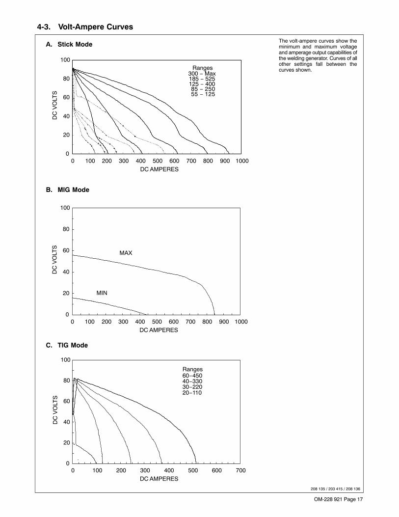
OM-228 921 Page 17
4-3. Volt-Ampere Curves
208 135 / 203 415 / 208 136
The volt-ampere curves show theminimum and maximum voltageand amperage output capabilities ofthe welding generator. Curves of allother settings fall between thecurves shown.
A. Stick Mode
B. MIG Mode
C. TIG Mode
0
20
40
60
80
100
0 100 200 300 400 500 600 700 800 900 1000DC AMPERES
DC
VO
LTS
MAX
MIN
0
20
40
60
80
100
0 100 200 300 400 500 600 700DC AMPERES
DC
VO
LTS
Ranges60−45040−33030−22020−110
0
20
40
60
80
100
0 100 200 300 400 500 600 700 800 900 1000DC AMPERES
DC
VO
LTS
Ranges300 − Max185 − 525125 − 400 85 − 250 55 − 125

OM-228 921 Page 18
4-4. Fuel Consumption
The curve shows typical fuel useunder weld or power loads.
208 137
US
GA
L./H
R.
1.980.95
2.843.78
5.674.73
6.627.57
LIT
ER
S/H
R.
0.00
8.519.46
10.4011.35
0.000.250.500.751.001.251.501.752.002.252.50
2.753.00
0 100 200 300 400 500 600 700
DC WELD AMPERES AT 100% DUTY CYCLE
Continuous Welding
4-5. Duty Cycle And Overheating
Duty Cycle is percentage of 10 min-utes that unit can weld at rated loadwithout overheating.
NOTICE − Exceeding duty cyclecan damage unit and void warranty.
100% Duty Cycle At 500 Amperes
202 356

OM-228 921 Page 19
4-6. Generator Power Curve
193 018
The AC power curve shows thegenerator power in amperes avail-able at the 120 and 240 voltreceptacles.
0
50
100
150
200
250
300
0 5 10 15 20 25 30AC AMPERES IN 240V MODE
AC
VO
LTS
0
25
50
75
100
150
125
0 10 20 30 40 50 60AC AMPERES IN 120V MODE
Notes
Work like a Pro!
Pros weld and cut
safely. Read the
safety rules at
the beginning
of this manual.

OM-228 921 Page 20
4-7. Optional Three-Phase Generator Curves
197 472 / 197 473
The AC power curves show thegenerator power available in am-peres at the single-phase 120/240volt receptacle or three-phase 240volt terminals.A. 12 kVA/kW Single-Phase AC Output (No Weld Load)
B. 20 kVA/kW Three-Phase AC Output (No Weld Load)
180190200
210220
230240
250260270
280
0 20 40 60 80 100
AC AMPERES
AC
VO
LTS
180
200
220
240
260
280
0 10 20 30 40 50 60 70
AC AMPERES
90
95100
105110115
120125
130135140
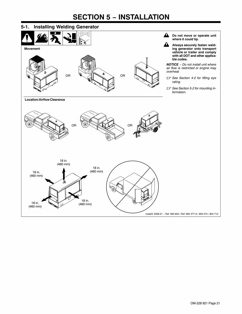
OM-228 921 Page 21
SECTION 5 − INSTALLATION
! Do not move or operate unitwhere it could tip.
! Always securely fasten weld-ing generator onto transportvehicle or trailer and complywith all DOT and other applica-ble codes.
NOTICE − Do not install unit whereair flow is restricted or engine mayoverheat.
� See Section 4-2 for lifting eyerating.
� See Section 5-2 for mounting in-formation.
install3 2008-01 − Ref. 800 652 / Ref. 800 477-A / 803 274 / 804 712
18 in.(460 mm)
18 in.(460 mm)
18 in.(460 mm)
18 in.(460 mm)
18 in.(460 mm)
Movement
5-1. Installing Welding Generator
OR OR
OR
Location/Airflow Clearance
OR

OM-228 921 Page 22
5-2. Mounting Welding Generator
Tools Needed:
9/16 in.
2
2
4
Welding Unit In Place
Bolting Unit In Place
! Do not weld on base. Weld-ing on base can cause fueltank fire or explosion. Weldonly on the four mountingbrackets or bolt unit down.
NOTICE − Do not mount unit bysupporting the base only at the fourmounting brackets. Use cross-supports to adequately support unitand prevent damage to base.
Mounting Surface:
1 Cross-Supports
2 Mounting Brackets (Supplied)
Mount unit on flat surface or usecross-supports to support base.Secure unit with mounting brack-ets.
3 1/2 in. Bolt And Washer(Minimum − Not Supplied)
4 3/8-16 x 1 in. Screws(Supplied)
To Bolt Unit In Place:
Remove hardware securing thefour mounting brackets to the base.Reverse brackets and reattach tobase with original hardware.
Mount unit to truck or trailer with 1/2in. (12 mm) or larger hardware (notsupplied).
To Weld Unit In Place:
Weld unit to truck or trailer only atthe four mounting brackets.
1
2
Supporting The Unit
Using Mounting Brackets
install3 2008--01 803 274 / 200 864-A / 803 231
1
OR
3

OM-228 921 Page 23
! Always ground generatorframe to vehicle frame to pre-vent electric shock and staticelectricity hazards.
! Also see AWS Safety &Health Fact Sheet No. 29,Grounding of Portable AndVehicle Mounted WeldingGenerators.
! Bed liners, shipping skids,and some running gear insu-late the welding generatorfrom the vehicle frame. Al-ways connect a ground wirefrom the generator equip-ment grounding terminal tobare metal on the vehicleframe as shown.
! If unit does not have GFCI re-ceptacles, use GFCI-pro-tected extension cord.
1 Equipment GroundingTerminal (On Front Panel)
2 Grounding Cable (NotSupplied)
3 Metal Vehicle Frame
Connect cable from equipmentground terminal to metal vehicleframe. Use #10 AWG or largerinsulated copper wire.
� Electrically bond generatorframe to vehicle frame by met-al-to-metal contact.
5-3. Grounding Generator To Truck Or Trailer Frame
rot_grnd 2008-01 − 800 652-D
1
3
2
GND/PE
4 Rating Label − Typical
Locate rating label on unit. Label pro-vides information such as weld outputratings, generator ratings, and engineinformation.
� Evidence of label tampering voidswarranty.
rot_label 2008-01 − 804 712
1
5-4. Rating Label Location

OM-228 921 Page 24
5-5. Using Lifting Eye
Lift1 2008−01 804 712
1 Lifting Eye
2 Nut
3 Carriage Bolt
Raise lifting eye until it snaps inplace. Lower lifting eye when notneeded.
To lock the lifting eye in the uprightposition, insert a 3/8-16 x 1-1/2 in.carriage bolt through slot in bracketand secure with nut (bolt and nut notsupplied).
Tools Needed:
2
1
3
5-6. Installing Exhaust Pipe
1/2 in.
Tools Needed:
Exhaust1 2008−01 Ref. 803 604 / Ref. 202 705
! Stop engine and let cool.
� Point exhaust pipe in desired di-rection but always away from frontpanel and direction of travel.

OM-228 921 Page 25
5-7. Activating The Dry Charge Battery (If Applicable)
! Always wear a face shield,rubber gloves and protectiveclothing when working on abattery.
Remove battery from unit.
1 Vent Caps
2 Sulfuric Acid Electrolyte(1.265 Specific Gravity)
3 Well
Fill each cell with electrolyte tobottom of well (maximum).
! Do not overfill battery cells.
Wait ten minutes and check electro-lyte level. If necessary, add electro-lyte to raise to proper level. Reins-tall vent caps.
4 Battery Charger
! Read and follow all instruc-tions supplied with batterycharger.
5 5 Amperes For 30 MinutesCharge Time
6 30 Amperes For 12 MinutesCharge Time
Charge battery. Disconnect charg-ing cables and install battery.
� When electrolyte is low, addonly distilled water to cells tomaintain proper level.
1
Tools Needed:
2
4
+
−
3
drybatt1 2008−01 − S-0886
5
6
30 A
5 A
5-8. Connecting The Battery
1/2 in.
−
+
Tools Needed:
Conn_batt1 2008−02 802 168-E / Ref. 202 705 / 802 313 / S-0756-C
! Connect negative (−) batterycable last.
� Reinstall cover after connectingbattery.

OM-228 921 Page 26
5-9. Engine Prestart Checks
� Check all engine fluids daily.
Engine must be cold and on a level surface.Unit is shipped with 20W break-in oil. TheAutomatic shutdown system stops engine ifoil pressure is too low or coolant tempera-ture is too high.
� This unit has a low oil pressure shut-down switch. However, some condi-tions may cause engine damage beforethe engine shuts down. Check oil leveloften and do not use the oil pressureshutdown system to monitor oil level.
Follow run-in procedure in engine manual.If unburned fuel and oil collect in exhaustpipe during run-in, see Section 10.
Fuel
NOTICE − Do not use gasoline. Gasolinewill damage engine.
NOTICE − Do not use ether to start engine.
Add fresh diesel fuel before starting to pre-vent air from entering the fuel system (see
engine maintenance label for fuel specifica-tions). Leave filler neck empty to allow roomfor expansion.
Engine stops if fuel level is low.
Oil
After fueling, check oil with unit on level sur-face. If oil is not up to full mark on dipstick,add oil (see maintenance label).
NOTICE − Engine may use oil and wets-tacking may occur during run-in. Check oilseveral times daily during run-in.
Coolant
Check coolant level in radiator before start-ing unit the first time. Add coolant if belowbottom of filler neck (see Section 5-10 for ra-diator filling instructions).
Check coolant level in recovery tank daily.If coolant is below Cold Full level, add cool-ant until level in tank is between Cold Fulland Hot Full levels. If recovery tank coolantlevel was low, check coolant level in radiator(see Section 5-10).
Engine coolant is a mixture of water andethylene glycol base antifreeze. A solutionof 50% antifreeze and 50% water must beused in this engine. Do not use 100% anti-freeze or severe damage will occur.
Keep radiator and air intake clean.
NOTICE − Incorrect engine temperaturecan damage engine. Do not run engine with-out a properly working thermostat and ra-diator cap.
� To improve cold weather starting:Use Engine Start/Preheat switch to op-erate glow plug (see Section 6-1).
Keep battery in good condition. Storebattery in warm area.
Use fuel formulated for cold weather(diesel fuel can gel in cold weather).Contact local fuel supplier for fuel in-formation.
Use correct grade oil for cold weather(see Section 8-1).
Full
Diesel
Full
Full
Capacity: w/OverflowTank 10 qt (9.5 L)
Check radiator coolantlevel when fluid is low in
recovery tank.
Remove air bleed screwwhen filling radiator.
See Section 5-10.
Full
Coolant RecoveryTank
804 583-A

OM-228 921 Page 27
1
5-10. Adding Coolant To Radiator
804 583-A / 228 923
! Stop engine and let cool.
� Check coolant level accordingto Section 5-9 before startingthis procedure.
Engine coolant is a mixture of waterand ethylene glycol base anti-freeze. A solution of 50% antifreezeand 50% water must be used in thisengine. Do not use 100% antifreezeor severe damage will occur.
If coolant level is below bottom ofradiator filler neck, add coolant asfollows:
1 Radiator Air Bleed Screw2 Radiator Cap
Remove air bleed screw. Add cool-ant to radiator until coolant is at bot-tom of filler neck. This ensures allair is purged from the system.
Reinstall air bleed screw and radia-tor cap. Check coolant level in re-covery tank (see Section 5-9).
Full
Capacity: w/OverflowTank 10 qt (9.5 L)
Tools Needed:
3/8 in.
2

OM-228 921 Page 28
5-11. Connecting To Weld Output Terminals
804 582 / 228 923 / 803 778-B
Tools Needed:
83/4 in.
7
MIG and FCAW WeldingFor MIG and FCAW welding Direct CurrentElectrode Positive (DCEP) on CC/CV models,connect wire feeder cable to Positive (+) termi-nal on left and work cable to Negative (−) ter-minal on right. Use Process/Contactor switchto select type of weld output (see Section 6-3).
For Direct Current Electrode Negative(DCEN), reverse cable connections.
If equipped with optional Polarity switch or op-tional Polarity/AC switch, connect wire feedercable to Electrode (+) terminal on left andwork cable to Work (−) terminal on right.
6
4
5
3
! Stop engine.
! Failure to properly connect weldcables may cause excessive heat andstart a fire, or damage your machine.
� Do not place anything between weld cableterminal and copper bar. Make sure thatthe surfaces of the weld cable terminaland copper bar are clean.
1 Correct Weld Cable Connection
2 Incorrect Weld Cable Connection
3 Weld Output Terminal
4 Supplied Weld Output Terminal Nut
5 Weld Cable Terminal
6 Copper Bar
Remove supplied nut from weld output termi-nal. Slide weld cable terminal onto weld outputterminal and secure with nut so that weld cableterminal is tight against copper bar.
7 Positive (+) Weld Output Terminal
8 Negative (−) Weld Output Terminal
Stick and TIG WeldingFor Stick and TIG welding Direct Current Elec-trode Positive (DCEP), connect electrodeholder cable to Positive (+) terminal on left andwork cable to Negative (−) terminal on right.
For Direct Current Electrode Negative(DCEN), reverse cable connections.
If equipped with optional Polarity switch or op-tional Polarity/AC switch, connect electrodeholder cable to Electrode (+) terminal on leftand work cable to Work (−) terminal on right.
2
1

OM-228 921 Page 29
5-12. Selecting Weld Cable Sizes*
Weld Cable Size** and Total Cable (Copper) Length in Weld CircuitNot Exceeding***
100 ft (30 m) or Less 150 ft(45 m)
200 ft(60 m)
250 ft(70 m)
300 ft(90 m)
350 ft(105 m)
400 ft(120 m)
Weld OutputTerminals
! Stop engine beforeconnecting to weldoutput terminals.
! Do not use worn, dam-aged, undersized, orpoorly spliced cables.
WeldingAmperes
10 − 60%DutyCycle
60 − 100%DutyCycle
10 − 100% Duty Cycle
100 4 (20) 4 (20) 4 (20) 3 (30) 2 (35) 1 (50) 1/0 (60) 1/0 (60)
150 3 (30) 3 (30) 2 (35) 1 (50) 1/0 (60) 2/0 (70) 3/0 (95) 3/0 (95)
200 3 (30) 2 (35) 1 (50) 1/0 (60) 2/0 (70) 3/0 (95) 4/0 (120) 4/0 (120)
250 2 (35) 1 (50) 1/0 (60) 2/0 (70) 3/0 (95) 4/0 (120)2 ea. 2/0(2x70)
2 ea. 2/0(2x70)
300 1 (50) 1/0 (60) 2/0 (70) 3/0 (95) 4/0 (120)2 ea. 2/0(2x70)
2 ea. 3/0(2x95)
2 ea. 3/0(2x95)
350 1/0 (60) 2/0 (70) 3/0 (95) 4/0 (120)2 ea. 2/0(2x70)
2 ea. 3/0(2x95)
2 ea. 3/0(2x95)
2 ea. 4/0(2x120)
400 1/0 (60) 2/0 (70) 3/0 (95) 4/0 (120)2 ea. 2/0(2x70)
2 ea. 3/0(2x95)
2 ea. 4/0(2x120)
2 ea. 4/0(2x120)
500 2/0 (70) 3/0 (95) 4/0 (120)2 ea. 2/0(2x70)
2 ea. 3/0(2x95)
2 ea. 4/0(2x120)
3 ea. 3/0(3x95)
3 ea. 3/0(3x95)
600 3/0 (95) 4/0 (120)2 ea. 2/0(2x70)
2 ea. 3/0(2x95)
2 ea. 4/0(2x120)
3 ea. 3/0(3x95)
3 ea. 4/0(3x120)
3 ea. 4/0(3x120)
700 4/0 (120)2 ea. 2/0(2x70)
2 ea. 3/0(2x95)
2 ea. 4/0(2x120)
3 ea. 3/0(3x95)
3 ea. 4/0(3x120)
3 ea. 4/0(3x120)
4 ea. 4/0(4x120)
* This chart is a general guideline and may not suit all applications. If cables overheat, use next size larger cable.
**Weld cable size (AWG) is based on either a 4 volts or less drop or a current density of at least 300 circular mils per ampere.( ) = mm2 for metric use S-0007-F
***For distances longer than those shown in this guide, call a factory applications representative.
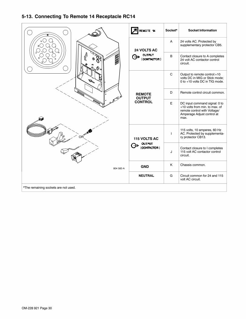
OM-228 921 Page 30
5-13. Connecting To Remote 14 Receptacle RC14
OR
804 582-A
Socket* Socket Information
24 VOLTS AC
A 24 volts AC. Protected bysupplementary protector CB5.
B Contact closure to A completes24 volt AC contactor controlcircuit.
REMOTEOUTPUT
CONTROL
C Output to remote control:+10volts DC in MIG or Stick mode;0 to +10 volts DC in TIG mode.
D Remote control circuit common.
E DC input command signal: 0 to+10 volts from min. to max. ofremote control with Voltage/Amperage Adjust control atmax.
115 VOLTS ACI
115 volts, 10 amperes, 60 HzAC. Protected by supplementa-ry protector CB13.
JContact closure to I completes115 volt AC contactor controlcircuit.
GND K Chassis common.
NEUTRAL G Circuit common for 24 and 115volt AC circuit.
*The remaining sockets are not used.

OM-228 921 Page 31
Notes
16 Gauge (.063 in)
22 Gauge (.031 in)
24 Gauge (.025 in)
20 Gauge (.037 in)
18 Gauge (.050 in)
14 Gauge (.078 in)
1/8 in (.125 in)
3/16 in (.188 in)
1/4 in (.25 in)
5/16 in (.313 in)
3/8 in (.375 in)
1/2 in (.5 in)
MATERIAL THICKNESS REFERENCE CHART

OM-228 921 Page 32
SECTION 6 − OPERATING WELDING GENERATOR
6-1. Front Panel Controls (See Section 6-2)
236 982-A / 804 582-A
7
10
2
1
8 12
9
5
6
4
3
11

OM-228 921 Page 33
6-2. Description Of Front Panel Controls (See Section 6-1)
Engine Starting Controls
1 Start/Preheat Switch
Use switch to start engine and operate glowplug for cold weather starting.
Engine runs at weld/power speedcontinuously.
Turn switch to Preheat position to operate theglow plug and heat the combustion chambersbefore cranking engine (see starting instruc-tions following).
2 Engine Shutdown Switch
Push switch down to stop engine.
To Start:
NOTICE − Do not use ether to start engine.
� If engine does not start, let engine come toa complete stop before attempting restart.
Above 41� F (5� C): turn Start/Preheat switchto Preheat position for 5 seconds and then turnswitch to Start position. Release Start/Preheatswitch when engine starts.
Below 41� F (5� C):Turn Start/Preheat switch to Preheat positionfor 15 seconds and then turn switch to Start.Release Start/Preheat switch when enginestarts.
To Stop:
Push Engine Shutdown switch down to stopengine.
Engine Gauges
� To read gauges with engine off, turn Start/Preheat switch to Preheat position.
3 Engine Fuel/Hour Gauge
Use meter to monitor engine running time for
scheduling maintenance.
Use gauge to check fuel level. Engine stops iffuel level is low.
To check fuel level when engine is not runningplace Engine Control switch in Preheat posi-tion then default back to neutral position.
See Section 6-5 for complete fuel/hour gaugeinformation.
4 Battery Ammeter
Use gauge to check amperage output to thebattery. The gauge reads near 0 (zero) whenthe engine is running. If gauge is at a negativenumber, the battery is discharging.
NOTICE − Stop engine, and do not run engineuntil problem is fixed.
5 Engine Temperature Gauge
Normal temperature is 170 - 205° F (77 - 96°C). Engine stops if temperature exceeds 221°F (105° C).
Weld Controls6 Process/Contactor Control SwitchSee Section 6-3 for Process/Contactor Con-trol switch information.
7 Amperage Range Switch
NOTICE − Do not switch under load.
Use switch to select weld amperage range.
Use the lowest four ranges for Stick and TIGwelding. Read the upper set of numbers ateach range for Stick welding and the lower setat each range for TIG welding.
Use the highest range for MIG welding and forcutting and gouging (CAC-A).
For most welding applications, use lowest am-perage range possible to help prevent arc out-ages.
8 Voltage/Amperage Adjust Control
With Process/Contactor Control switch in anyStick or TIG setting, use control to adjust am-perage within range selected by AmperageRange switch. With Process/Contactor Con-trol switch in any MIG position, use control toadjust voltage. With Voltage/Amperage AdjustControl switch (item 9) in Remote position,control limits the remote amperage in TIGmode, but has no effect in Stick and MIGmodes.
Weld output would be about 263 A DC withcontrols set as shown (50% of 125 to 400 A).
� The numbers around the control are forreference only and do not represent an ac-tual percentage value.
9 Voltage/Amperage Adjust Control SwitchAnd Remote 14 Receptacle
Use switch to select front panel or remote volt-age/amperage control. For remote control,place switch in Remote position and connectremote control to Remote 14 receptacle RC14(see Sections 5-13 and 6-4).
10 Polarity/AC Selector Switch (Optional)
NOTICE − Do not switch under load.
Use switch to change weld output. Select ei-ther DC Electrode Positive (DCEP) or DCElectrode Negative (DCEN).
Weld Meters
11 DC Voltmeter (Optional)
Voltmeter displays voltage at the weld outputterminals, but not necessarily the welding arcdue to resistance of cable and connections.
12 DC Ammeter (Optional)
Ammeter displays amperage output of the unit.

OM-228 921 Page 34
6-3. Process/Contactor Control Switch
1 Process/Contactor Control Switch(See Section 6-1 For Location)
! Weld output terminals are energizedwhen Process/Contactor Controlswitch is in a Weld Terminals AlwaysOn position and the engine isrunning.
Use switch to select weld process and weldoutput on/off control (see table below and
Section 6-4).
Place switch in Weld Terminals RemotelyControlled positions to turn weld output onand off with a device connected to the re-mote 14 receptacle.
Place switch in Weld Terminals Always Onpositions for weld output to be on wheneverthe engine is running.
Use Weld Terminals Always On − CC Stickposition for air carbon arc (CAC-A) cuttingand gouging.When switch is in a Weld Terminals AlwaysOn − CC Stick position, the arc drive (dig)circuit provides additional amperage duringlow voltage (short arc length conditions) toprevent “sticking” electrodes.The arc drive (dig) circuit is disabled whenswitch is in MIG, TIG, and CC stick (WithRemote On/Off Control) positions.
1
236 982-A
Process/Contactor Control Switch Settings
Switch Setting Process Output On/Off Control
Weld Terminals Remotely Controlled − CC TIG GTAW With HF Unit, Pulsing Device,
Or Remote Control At Remote 14 Receptacle
Weld Terminals Remotely Controlled − CC Stick Stick (SMAW) With Remote On/Off At Remote 14 Receptacle
Weld Terminals Remotely Controlled − CV MIG MIG (GMAW) At Remote 14 Receptacle
Weld Terminals Always On − CV MIG MIG (GMAW) Electrode Hot
Weld Terminals Always On − CC StickStick (SMAW),
Air Carbon Arc (CAC-A) Cutting And Gouging Electrode Hot
Weld Terminals Always On − CC Scratch Start TIG Scratch Start TIG (GTAW) Electrode Hot

OM-228 921 Page 35
6-4. Remote Voltage/Amperage Control
1 Remote 14 Receptacle RC14
Connect optional remote control toRC14 (see Section 5-13).
0774 / Ref. 192 895-A / 804 582-A / 236 982-A
Example: Combination Remote Amperage Control (Stick) With Remote On/Off Control In Example:Process = Stick (Using Remote On/Off)
Range = 125 to 400 A DCMin = 125 A DCMax = 400 A DC
Adjust Optional Remote ControlSet V/AAdjust Switch
Set Range Control NotUsed In Remote
Stick Mode
Max (400 A DC)
Min (125 A DC)
Set RemoteProcess
Example: Combination Remote Amperage Control (TIG) With Remote On/Off Control In Example:Process = TIG (Using Remote On/Off)
Range = 40 to 330 A DCPercentage Of Range = 50%
Min = 40 A DCMax = About 185 A DC (50% of 40 to 300)
Adjust Optional Remote ControlSet V/AAdjust Switch
Set Range Set Control
Max (185 A DC)
Min (40 A DC)
Set RemoteProcess
1
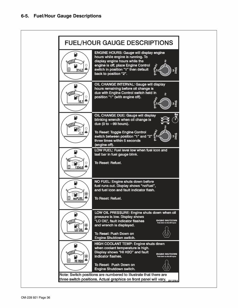
OM-228 921 Page 36
6-5. Fuel/Hour Gauge Descriptions

OM-228 921 Page 37
SECTION 7 − OPERATING AUXILIARY EQUIPMENT
7-1. 120 Volt And 240 Volt Receptacles
21
191 624
3
4
� Generator power is not af-fected by weld output.
1 120 V 20 A AC GFCI Receptacle GFCI1
2 240 V 30 A AC TwistlockReceptacle RC1
Receptacles supply 60 Hz single-phase power at weld/power speed.
If a ground fault is detected, GFCIReset button pops out andreceptacle does not work. Checkfor faulty tools plugged inreceptacle. Press button to resetGFCI1.
� At least once a month, run en-gine at weld/power speed andpress test button to verify GFCIis working properly.
3 Supplementary Protector CB1
4 Supplementary Protector CB2
CB1 protects RC1 and the genera-tor winding from overload. If CB1opens, RC1 and GFCI1 do notwork. Place switch in On position toreset.
CB2 protects GFCI1 from overload.If CB2 opens, GFCI1 does notwork. Press button to reset.
Maximum output is 2.4 kVA/kWfrom GFCI1 and 4 kVA/kW fromRC1. Maximum output from all re-ceptacles is 4 kVA/kW.
EXAMPLE: If 13 A is drawn fromRC1, only 7 A is available at GFCI1:
(240 V x 13 A) + (120 V x 7 A) = 4.0 kVA/kW
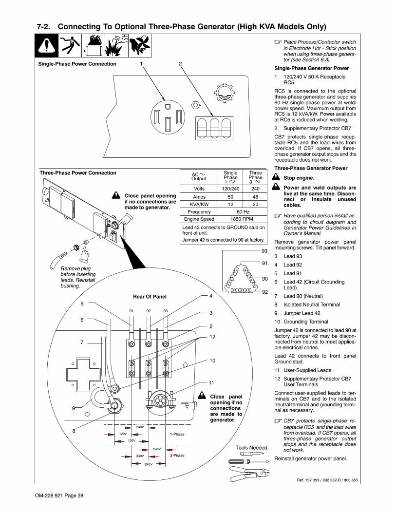
OM-228 921 Page 38
7-2. Connecting To Optional Three-Phase Generator (High KVA Models Only)
Ref. 197 399 / 802 332-B / 803 655
� Place Process/Contactor switchin Electrode Hot - Stick positionwhen using three-phase genera-tor (see Section 6-3).
Single-Phase Generator Power
1 120/240 V 50 A ReceptacleRC5
RC5 is connected to the optionalthree-phase generator and supplies60 Hz single-phase power at weld/power speed. Maximum output fromRC5 is 12 kVA/kW. Power availableat RC5 is reduced when welding.
2 Supplementary Protector CB7
CB7 protects single-phase recep-tacle RC5 and the load wires fromoverload. If CB7 opens, all three-phase generator output stops and thereceptacle does not work.
Three-Phase Generator Power
! Stop engine.
! Power and weld outputs arelive at the same time. Discon-nect or insulate unusedcables.
� Have qualified person install ac-cording to circuit diagram andGenerator Power Guidelines inOwner’s Manual.
Remove generator power panelmounting screws. Tilt panel forward.
3 Lead 93
4 Lead 92
5 Lead 91
6 Lead 42 (Circuit GroundingLead)
7 Lead 90 (Neutral)
8 Isolated Neutral Terminal
9 Jumper Lead 42
10 Grounding Terminal
Jumper 42 is connected to lead 90 atfactory. Jumper 42 may be discon-nected from neutral to meet applica-ble electrical codes.
Lead 42 connects to front panelGround stud.
11 User-Supplied Leads
12 Supplementary Protector CB7User Terminals
Connect user-supplied leads to ter-minals on CB7 and to the isolatedneutral terminal and grounding termi-nal as necessary.
� CB7 protects single-phase re-ceptacle RC5 and the load wiresfrom overload. If CB7 opens, allthree-phase generator outputstops and the receptacle doesnot work.
Reinstall generator power panel.
Tools Needed:
Volts
Amps
KVA/KW
Single
120/240
50
12
Three
240
48
20
60 HzFrequency
Engine Speed 1850 RPM
AC Phase1
Phase3
Output
Lead 42 connects to GROUND stud onfront of unit.Jumper 42 is connected to 90 at factory.
1 2
91 92 93
240V
120V
120V
240V
240V
1-Phase
3-Phase
3
4
5
6
7
8
9
10
11
12
Rear Of Panel
Three-Phase Power Connection
2
Single-Phase Power Connection
92
90
91
93
! Close panel openingif no connections aremade to generator.
! Close panelopening if noconnectionsare made togenerator.
240V
Remove plugbefore insertingleads. Reinstallbushing.

OM-228 921 Page 39
SECTION 8 − MAINTENANCE & TROUBLESHOOTING
8-1. Maintenance Label

OM-228 921 Page 40
8-2. Routine Maintenance
! Stop engine before maintaining.
� See Engine Manual and Maintenance Labelfor important start-up, service, and storageinformation. Service engine more often ifused in severe conditions.
Recycle enginefluids.
� = Check � = Change � = Clean � = Replace* To be done by Factory Authorized Service Agent. . . . . . . . . . . . . . . . . . . . . . . . . . . . . . . . . . . . . . . . . . . . . . . . . . . .
Reference
Every8Hours
Section 5-6
� Coolant Level � Fuel Level� Sedimenter Bowl
� Oil Level � Oil, Fuel Spills
Every50Hours
� Fuel Connections � Weld Terminals
Every100Hours
5/16 in.(8 mm)
Section 8-3,EngineManual
� Air Cleaner Element � Air Cleaner Hoses � Belt Tension � Battery Terminals
Every200Hours
Section 8-7
� Oil � Oil Filter � Radiator Hoses � Unreadable Labels
Every500Hours
EngineManual,Section 8-4,8-8
� Fan Belt � Radiator Exterior �� Weld Cables �� Optional SparkArrestor
Every800Hours
Section 8-7,EngineManual
� Valve Clearance* � Fuel Filter � Fuel Sedimenter Filter
Every1000Hours
ORFUEL
SLUDGE
EngineManual,Section 8-5,8-7
� Inside Unit � Drain Sludge �� Slip Rings*�� Brushes*
Every1500Hours
� Injectors
EveryYear
Section 8-3
�� Air Filter Elements
Every2Years
Section 8-8,EngineManual
�� Coolant And Hoses

OM-228 921 Page 41
8-3. Servicing Air Cleaner
aircleaner1 9/00 − ST-153 929-B / ST-153 585 / Ref. S-0698-B
! Stop engine.
NOTICE − Do not run engine without aircleaner or with dirty element. Enginedamage caused by using a damaged ele-ment is not covered by the warranty.
� The air cleaner primary element canbe cleaned but the dirt holding capac-ity of the filter is reduced with eachcleaning. The chance of dirt reachingthe clean side of the filter while clean-ing and the possibility of filter damagemakes cleaning a risk. Consider therisk of unwarrantable equipmentdamage when determining whetherto clean or replace the primary ele-ment.
If you decide to clean the primary ele-ment, we strongly recommend instal-ling an optional safety element to pro-vide additional engine protection.Never clean a safety element. Re-place the safety element after servic-ing the primary element three times.
Clean or replace primary element if dirty(see note above before cleaning). Re-place primary element if damaged. Re-place primary element yearly or after sixcleanings.
1 Housing
2 Safety Element (Optional)
3 Primary Element
4 Dust Cap
5 Dust Ejector
To clean air filter:
Wipe off cap and housing. Remove capand dump out dust. Remove element(s).Wipe dust from inside cap and housingwith damp cloth. Reinstall safety element(if present). Reinstall cap.
NOTICE − Do not clean housing with airhose.
Clean primary element with compressedair only.
Air pressure must not exceed 100 psi(690 kPa). Use 1/8 in. (3 mm) nozzle andkeep nozzle at least 2 in. (51 mm) frominside of element. Replace primary ele-ment if it has holes or damaged gaskets.
Reinstall primary element and cap (dustejector down).
Blow Inspect
41 3
5
Keep nozzle2 in. (51 mm)from element.
2
Optional

OM-228 921 Page 42
8-4. Inspecting/Cleaning Optional Spark Arrestor
Ref. 228 923-A / 804 582-A
! Stop engine and let cool.
1 Spark Arrestor Muffler
2 Cleanout Plug
Remove plug and remove any dirtcovering cleanout hole.
3 Exhaust Pipe With Rain Cap
Start engine and run at idle speed toblow out cleanout hole. If nothingblows out of hole, briefly cover endof exhaust pipe with fireproofmaterial.
! Stop engine and let cool.
Reinstall cleanout plug.
Tools Needed:
3
2
1
3/8 in.
8-5. Checking Generator Brushes
Ref. 228 923−A
! Stop engine and let cool.
1 Generator Brush
Remove brushes from brush holder.
Replace brushes if damaged or if brushmaterial is at or near minimum length.
1Damaged Brushes
New Length: 1-1/4 in. (32 mm)
Minimum Length:5/8 in. (16 mm)
Replace

OM-228 921 Page 43
8-6. Adjusting Engine Speed
804 583-A / Ref. 228 932-A
! Stop engine and let cool.
Engine speed is factory set andshould not require adjustment. Af-ter tuning engine, check engine noload speed with a tachometer or fre-quency meter (see table for no loadspeeds). If necessary, adjust speedas follows:
Start engine and run until warm.
Turn Process/Contactor Controlswitch to Stick − Electrode Hotposition.
1 Engine Speed AdjustmentScrew
2 Locking Nut
Loosen nut. Turn screw until engineruns at weld/power speed. Tightennut.
� Do not set engine speed higherthan specified.
3 Engine Shutdown Lever
Use lever to stop engine if EngineShutdown switch does not work.
! Stop engine.
Close door.
12
1850 rpm Max.(61.6 Hz)
Tools Needed:
3

OM-228 921 Page 44
8-7. Servicing Fuel And Lubrication Systems
Ref. 800 159-E / Ref. 802 170 / 804 583-B
! Stop engine and let cool.
! After servicing, start engine andcheck for fuel leaks. Stop engine,tighten connections as necessary,and wipe up spilled fuel.
1 Oil Filter2 Oil Drain Valve And Hose3 Oil Fill Cap4 Fuel Sedimenter
5 Secondary Fuel Filter
6 Fuel Tank Sludge Drain Valve
To change oil and filter:Route oil drain hose and valve through holein base. See engine manual and enginemaintenance label for oil/filter change in-formation.
To drain water from fuel sedimenter:
Close fuel valve on top of sedimenter. Re-move bowl and dump water that has col-lected in bowl. Clean sedimenter filter ac-cording to maintenance label.
To replace secondary fuel filter:
Turn filter counterclockwise. Remove filter.
Apply thin coat of fuel to gasket on new filter.Fill filter with fuel. Install filter and turn clock-wise. Bleed air from fuel system accordingto engine manual.
Inspect fuel line, and replace if cracked orworn.
Close doors.
To drain sludge from fuel tank:
! Beware of fire. Do not smoke andkeep sparks and flames away fromdrained fuel. Dispose of drained fuelin an environmentally-safe manner.Do not leave unit unattended whiledraining fuel tank.
! Properly lift unit and secure in a levelposition. Use adequate blocks orstands to support unit while drain-ing fuel tank.
Attach 1/2 ID hose to drain valve. Put metalcontainer under drain, and use screwdriverto open sludge drain valve. Close valvewhen sludge has drained. Remove hose.
Tools Needed:
26
4
Right Side
3
5
1

OM-228 921 Page 45
8-8. Servicing Engine Cooling System
Ref. 804 583-A / Ref. 803 136
! Stop engine and let cool.
1 Radiator Cap
2 RAdiator Air Bleed Screw
3 Radiator Drain Cock
Drain engine coolant according toprocedure in engine manual.
Add engine coolant according toprocedure in Section 5-10.
2
Tools Needed:
3
3/8 in.
1

OM-228 921 Page 46
8-9. Overload Protection
! Stop engine.
1 Fuse F1
2 Fuse F2
F1 and F2 protect the stator exciterwinding from overload. If F1 opens,weld and generator power is low orstops entirely. If F2 opens, weld out-put stops. 4 kVA/kW generator pow-er is still available.
3 Circuit Breaker CB4 (NotShown)
4 Supplementary Protector CB5
5 Circuit Breaker CB10 (NotShown)
6 Supplementary Protector CB11
7 Supplementary Protector CB12
8 Supplementary Protector CB13
CB4 protects the welding arc drive(dig) circuit. If CB4 opens, the elec-trode may stick to the workpiecemore frequently during low voltage(short arc length) conditions. CB4 au-tomatically resets when the fault iscorrected.
CB5 protects the 24 volt AC output toremote receptacle RC14, and 24 voltoutput to field current regulator boardPC1. If CB5 opens, weld output and24 volt output to RC14 stops.
CB10 protects the engine battery cir-cuit. If CB10 opens, the engine willnot crank. CB10 automatically resetswhen the fault is corrected.
CB11 protects the control box wiringharness. If CB11 opens, weld outputstops (generator power is still avail-able).
CB12 protects the field flashing cir-cuit. If CB12 opens, the generatormay not excite at start-up and weldand generator power output may notbe available.
CB13 protects the 115 volt AC outputto remote receptacle RC14. If CB13opens, 115 volt output to RC14stops.
Press button to reset supplementaryprotector.
2 1
76
4
Ref. 804 582-A / 802 170-D / Ref. 802 313
8

OM-228 921 Page 47
8-10. Troubleshooting Tables
A. Welding
Trouble Remedy
No weld output; generator power outputokay at AC receptacles.
Place Process/Contactor switch S6 in a Weld Terminals Always On position, or place switch in a WeldTerminals Remotely Controlled position and connect remote contactor to optional Remote 14 receptacleRC14 (see Sections 5-13, 6-3 and 6-4).
Check position of Amperage Range switch S3.
Check position of optional Polarity/AC Selector switch S13.
Reset supplementary protector CB11 (see Section 8-9).
Reset supplementary protector CB5 (see Section 8-9). Check for faulty remote device connected toRC14.
Check fuse F2, and replace if open (see Section 8-9).
Check and secure connections to Remote 14 receptacle RC14 (see Section 5-13).
Have Facotry Authorized Service Agent check connector board PC6 and connections; brushes and sliprings; field excitation circuit; field current regulator board PC1; and the rotor.
No weld output or generator power out-put at AC receptacles.
Disconnect equipment from generator power receptacles during start-up.
Reset supplementary protector CB12 (see Section 8-9).
Check fuses F1 and F2, and replace if open (see Section 8-9).
Have Factory Authorized Service Agent check integrated rectifier SR1, capacitor C9, field current regula-tor board PC1, and rotor.
Erratic weld output. Use dry, properly stored electrodes.
Be sure connection to work piece is clean and tight.
Remove excessive coils from weld cables.
Check and tighten connections inside and outside unit.
High weld output. Check position of Amperage Range switch S3 and Voltage/Amperage Adjust control R1.
Check engine speed, and adjust if necessary (see Section 8-6).
Have Factory Authorized Service Agent check field current regulator board PC1.
Electrode sticks to the workpiece morefrequently during low voltage (short arclength) conditions.
Circuit breaker CB4 may be open. CB4 automatically resets when the fault is corrected (see Section 8-9).Have Factory Authorized Service Agent check transformer T1 and integrated rectifiers SR4 and SR5.
Low weld output. Check engine speed, and adjust if necessary (see Section 8-6).
Check fuses F1 and F2, and replace if open (see Section 8-9). Have Factory Authorized Service Agentcheck integrated rectifier SR1, capacitor C9, field current regulator board PC1, and rotor.
Low open-circuit voltage. Check engine speed, and adjust if necessary (see Section 8-6).
No remote fine amperage or voltagecontrol.
Place Voltage/Amperage Adjust Control switch S5 in Weld Terminals Remotely Controlled position.
Check and secure connections to Remote 14 receptacle RC14 (see Section 5-13).
Repair or replace remote control device.
Wire feeder does not work with weldinggenerator.
Reset supplementary protector CB5 or CB6 (see Section 8-9).
Check and secure connections to Remote 14 receptacle RC14 (see Section 5-13).

OM-228 921 Page 48
Trouble Remedy
Repair or replace wire feeder.
Low CV weld output. Set Amperage Range switch S3 to highest range.
Min or max CV weld output only. Check position of Voltage/Amperage Adjust control R1 and Voltage/Amperage Adjust Control switch S5.
Repair or replace remote control device.
Have Factory Authorized Service Agent check field current regulator board PC1 and connections.
B. Standard Generator Power
Trouble Remedy
No generator power output at AC recept-acles; weld output okay.
Reset receptacle supplementary protectors.
No generator power output at AC recept-acles; no weld output.
Disconnect equipment from generator power AC receptacles during start-up.
Reset supplementary protector CB12 (see Section 8-9). Have Factory Authorized Service Agent checkfield current regulator board PC1.
Check fuses F1 and F2, and replace if open (see Section 8-9). Have Factory Authorized Service Agentcheck integrated rectifier SR1, capacitor C9, and rotor.
Have Factory Authorized Service Agent check slip rings, install new brushes if necessary, and checkfield excitation circuit.
High output at generator power AC re-ceptacles.
Check engine speed, and adjust if necessary (see Section 8-6).
Have Factory Authorized Service Agent adjust generator power field current resistor R3.
Low output at generator power AC re-ceptacles.
Check engine speed, and adjust if necessary (see Section 8-6).
Check fuse F1, and replace if open (see Section 8-9). Have Factory Authorized Service Agent check inte-grated rectifier SR1, resistor R3, and Capacitor C9.
C. Three-Phase Generator Power
Trouble Remedy
No or low output at optional three-phase generator/receptacle RC5.
Place Process/Contactor switch in Weld Terminals Always On - Stick position (see Section 6-3).
Reset supplementary protector CB7 (see Section 7-2).
Reset supplementary protector CB5 (see Section 8-9).
Check engine weld/power speed, and adjust if necessary (see Section 8-6).
Have Factory Authorized Service Agent check brushes and slip rings, and field current regulator boardPC1.
High output at optional three-phasegenerator/receptacle RC5.
Check engine weld/power speed, and adjust if necessary (see Section 8-6).
Have Factory Authorized Service Agent check field current regulator board PC1, and PC1 voltagefeedback circuit.
Erratic output at optional three-phasegenerator/receptacle RC5.
Have Factory Authorized Service Agent check brushes and slip rings, and field current regulator boardPC1.
D. Engine
Trouble Remedy
Engine will not crank. Check battery, and replace if necessary.
Check battery connections and tighten if necessary.
Circuit breaker CB10 may be open. CB10 automatically resets when fault is corrected (see Section 8-9).Check engine wiring harness and components.

OM-228 921 Page 49
Trouble Remedy
Check engine wiring harness plug connections.
Have Factory Authorized Service Agent check continuity of Engine Start/Preheat switch S1, and replaceif necessary.
Engine cranks but does not start. Check fuel level.
Check battery and replace if necessary. Check engine charging system according to engine manual.
Have Factory Authorized Service Agent check electric fuel pump, fuel solenoid FS1, control relays CR1and CR2, engine oil pressure switch S12, engine coolant temperature switch, fuel/hour gauge, and En-gine Shutdown switch S7.
Air in fuel system. See engine manual.
Engine starts, but stops when Start/Pre-heat switch S1 is released.
Check coolant level. Automatic shutdown system stops engine if engine temperature is too high (see Sec-tions 5-9).
Have Facotry Authorized Service Agent check fuel/hour gauge and control relay CR5.
Engine hard to start in cold weather. Turn Start/Preheat switch S1 to Preheat position before starting (see Section or 6-1).
Have Factory Authorized Service Agent check glow plug and related wiring.
Keep battery in good condition. Store battery in warm area off cold surface.
Use fuel formulated for cold weather (diesel fuel can gel in cold weather). Contact local fuel supplier forfuel information.
Use correct grade oil for cold weather (see Section 8-1).
Engine suddenly stops. Check fuel level.
Check oil level. Automatic shutdown system stops engine if oil pressure is too low (see Sections 5-9).
Check coolant level. Automatic shutdown system stops engine if engine temperature is too high (see Sec-tions 5-9).
Have Factory Authorized Service Agent check control relay CR2 and fuel solenoid FS1.
Engine slowly stopped and cannot berestarted.
Check fuel level.
Check engine air and fuel filters (see Sections 8-3 and 8-7).
See engine manual.
Battery discharges between uses. Clean top of battery with baking soda and water solution; rinse with clear water.
Recharge or replace battery if necessary.
Periodically recharge battery (approximately every 3 months).
Engine uses oil during run-in period;wetstacking occurs.
Dry engine (see Section 10).
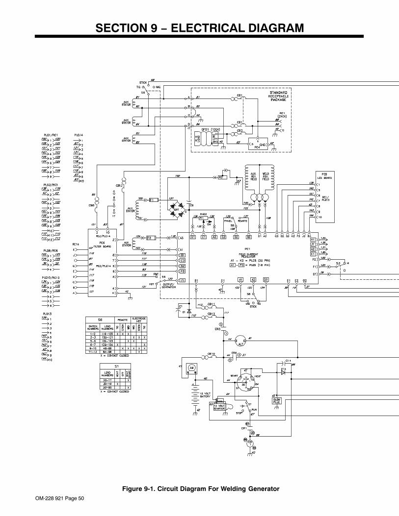
OM-228 921 Page 50
SECTION 9 − ELECTRICAL DIAGRAM
Figure 9-1. Circuit Diagram For Welding Generator

OM-228 921 Page 51
237 497-C

OM-228 921 Page 52
SECTION 10 − RUN-IN PROCEDURErun_in1 2007−04
10-1. Wetstacking
1 Welding Generator
Run diesel engines near rated volt-age and current during run-in periodto properly seat piston rings andprevent wetstacking. See name-plate, rating label, or specificationssection in this manual to find ratedvoltage and current.
NOTICE − Do not idle engine longerthan necessary. Piston rings seatfaster if engine runs at weld/powerrpm, and the welding generator iskept loaded during run-in.
2 Engine Exhaust Pipe
Wetstacking is unburned fuel andoil in the exhaust pipe and occursduring run-in if the engine is run toolong at light load or idle rpm.
If exhaust pipe is coated with a wet,black, tar-like substance, dry theengine using one of the followingrun-in procedures.
See the engine manual for addition-al engine run-in information.
2
1
NOTICE − Do not perform run-inprocedure at less than 20 voltsweld output and do not exceed dutycycle or equipment damage mayoccur.

OM-228 921 Page 53
10-2. Run-In Procedure Using Load Bank
S-0683
! Stop engine.
! Do not touch hot exhaustpipe, engine parts, or loadbank/grid.
! Keep exhaust and pipe awayfrom flammables.
NOTICE − Do not perform run-inprocedure at less than 20 volts weldoutput and do not exceed dutycycle or equipment damage mayoccur.
1 Load Bank
Turn all load bank switches Off. Ifneeded, connect load bank to 115volts ac wall receptacle or genera-tor auxiliary power receptacle.
2 Welding Generator
Place A/V range switch in maxi-mum position, A/V control in mini-mum position, and Output Selectorswitch (if present) in either DCposition.
3 Weld Cables
Connect load bank to generatorweld output terminals using propersize weld cables with correctconnectors. Observe correctpolarity.
Start engine and run for severalminutes.
Set load bank switches and thenadjust generator A/V control soload equals rated voltage andcurrent of generator (see name-plate, rating label, or the specifi-cations section in this manual).
Check generator and load bankmeters after first five minutes thenevery fifteen minutes to be suregenerator is loaded properly.
NOTICE − Check oil level frequent-ly during run-in; add oil if needed.
It is recommended to run the weld-ing generator for two hours mini-mum and up to four hours underload. Place A/V control in minimumposition, then turn off load bank toremove load. Run engine severalminutes at no load.
! Stop engine and let cool.
4 Engine Exhaust Pipe
Repeat procedure if wetstacking ispresent.
2
3
1
4

OM-228 921 Page 54
10-3. Run-In Procedure Using Resistance Grid
S-0684
! Stop engine.
! Do not touch hot exhaustpipe, engine parts, or loadbank/grid.
! Keep exhaust and pipe awayfrom flammables.
NOTICE − Do not perform run-inprocedure at less than 20 volts weldoutput and do not exceed dutycycle or equipment damage mayoccur.
1 Resistance Grid
Use grid sized for generator ratedoutput.
Turn Off grid.
2 Welding Generator
Place A/V range switch in maxi-mum position, A/V control in mini-mum position, and Output Selectorswitch (if present) in either DCposition.
3 Weld Cables
Connect grid to generator weldoutput terminals using proper sizeweld cables with correct connec-tors (polarity is not important).
4 Voltmeter
5 Clamp-On Ammeter
Connect voltmeter and ammeter asshown, if not provided on generator.
Start engine and run for severalminutes.
Set grid switches and then ad-just generator A/V control soload equals rated voltage andcurrent of the generator (seenameplate, rating label, or thespecifications section in thismanual).
Check generator and meters afterfirst five minutes then every fifteenminutes to be sure generator isloaded properly.
NOTICE − Check oil level frequent-ly during run-in; add oil if needed.
It is recommended to run the weld-ing generator for two hours mini-mum and up to four hours underload. Place A/V control in minimumposition, then shut down grid toremove load. Run engine severalminutes at no load.
! Stop engine and let cool.
6 Engine Exhaust Pipe
Repeat procedure if wetstacking ispresent.
1
3 5
+
4
2
6

OM-228 921 Page 55
SECTION 11 − GENERATOR POWER GUIDELINES� The views in this section are intended to be representative of all engine-driven welding generators. Your unit may differ from those shown.
11-1. Selecting Equipment
gen_pwr 2008−01 − ST-800 577
1 Generator Power Receptacles− Neutral Bonded To Frame
2 3-Prong Plug From CaseGrounded Equipment
3 2-Prong Plug From DoubleInsulated Equipment
� Be sure equipment has doubleinsulated symbol and/or word-ing on it.
! Do not use 2-prong plug un-less equipment is double in-sulated.
OR
2
3
1
! Always ground generatorframe to vehicle frame to pre-vent electric shock and staticelectricity hazards.
! Also see AWS Safety &Health Fact Sheet No. 29,Grounding of Portable AndVehicle Mounted WeldingGenerators.
1 Equipment GroundingTerminal (On Front Panel)
2 Grounding Cable (NotSupplied)
3 Metal Vehicle Frame
Connect cable from equipmentground terminal to metal vehicleframe. Use #10 AWG or largerinsulated copper wire.
� Electrically bond generatorframe to vehicle frame by met-al-to-metal contact.
! Bed liners, shipping skids,and some running gear insu-late the welding generatorfrom the vehicle frame. Al-ways connect a ground wirefrom the generator equip-ment grounding terminal tobare metal on the vehicleframe as shown.
! If unit does not have GFCI re-ceptacles, use GFCI-pro-tected extension cord.
11-2. Grounding Generator To Truck Or Trailer Frame
800 652-D
1
3
2
GND/PE

OM-228 921 Page 56
11-3. Grounding When Supplying Building Systems
ST-800 576-B
1 Equipment GroundingTerminal
2 Grounding Cable
Use #10 AWG or larger insulatedcopper wire.
3 Ground Device
� Use ground device as stated inelectrical codes.
! Ground generator to systemearth ground if supplyingpower to a premises (home,shop, farm) wiring system.
! Also see AWS Safety &Health Fact Sheet No. 29,Grounding of Portable AndVehicle Mounted WeldingGenerators.
GND/PE
1 2
2 3
11-4. How Much Power Does Equipment Require?
S-0623
1 Resistive Load
A light bulb is a resistive load andrequires a constant amount of power.
2 Non-Resistive Load
Equipment with a motor is a non-re-sistive load and requires approxi-mately six times more power whilestarting the motor than when running(see Section 11-8).
3 Rating Data
Rating shows volts and amperes, orwatts required to run equipment.
Amperes x Volts = Watts
Example 1: If a drill uses 4.5 am-peres at 115 volts, calculate its run-ning power requirement in watts.
4.5 A x 115 V = 520 W
The load applied by the drill is 520watts.
Example 2: If three 200 watt floodlamps are used with the drill from Ex-ample 1, add the individual loads tocalculate total load.
(3 x 200W) + 520 W = 1120 W
The total load applied by the threeflood lamps and drill is 1120 watts.
VOLTS 1154.560
AMPSHz1
2
3
3

OM-228 921 Page 57
11-5. Approximate Power Requirements For Industrial Motors
Industrial Motors Rating Starting Watts Running Watts
Split Phase 1/8 HP 800 300
1/6 HP 1225 500
1/4 HP 1600 600
1/3 HP 2100 700
1/2 HP 3175 875
Capacitor Start-Induction Run 1/3 HP 2020 720
1/2 HP 3075 975
3/4 HP 4500 1400
1 HP 6100 1600
1-1/2 HP 8200 2200
2 HP 10550 2850
3 HP 15900 3900
5 HP 23300 6800
Capacitor Start-Capacitor Run 1-1/2 HP 8100 2000
5 HP 23300 6000
7-1/2 HP 35000 8000
10 HP 46700 10700
Fan Duty 1/8 HP 1000 400
1/6 HP 1400 550
1/4 HP 1850 650
1/3 HP 2400 800
1/2 HP 3500 1100
11-6. Approximate Power Requirements For Farm/Home Equipment
Farm/Home Equipment Rating Starting Watts Running Watts
Stock Tank De-Icer 1000 1000
Grain Cleaner 1/4 HP 1650 650
Portable Conveyor 1/2 HP 3400 1000
Grain Elevator 3/4 HP 4400 1400
Milk Cooler 2900 1100
Milker (Vacuum Pump) 2 HP 10500 2800
FARM DUTY MOTORS 1/3 HP 1720 720
Std. (e.g. Conveyors, 1/2 HP 2575 975
Feed Augers, Air 3/4 HP 4500 1400
Compressors) 1 HP 6100 1600
1-1/2 HP 8200 2200
2 HP 10550 2850
3 HP 15900 3900
5 HP 23300 6800
High Torque (e.g. Barn 1-1/2 HP 8100 2000
Cleaners, Silo Unloaders, 5 HP 23300 6000
Silo Hoists, Bunk Feeders) 7-1/2 HP 35000 8000
10 HP 46700 10700
3-1/2 cu. ft. Mixer 1/2 HP 3300 1000
High Pressure 1.8 Gal/Min 500 PSI 3150 950
Washer 2 gal/min 550 PSI 4500 1400
2 gal/min 700 PSI 6100 1600
Refrigerator or Freezer 3100 800
Shallow Well Pump 1/3 HP 2150 750
1/2 HP 3100 1000
Sump Pump 1/3 HP 2100 800
1/2 HP 3200 1050

OM-228 921 Page 58
11-7. Approximate Power Requirements For Contractor EquipmentContractor Rating Starting Watts Running Watts
Hand Drill 1/4 in 350 350
3/8 in 400 400
1/2 in 600 600
Circular Saw 6-1/2 in 500 500
7-1/4 in 900 900
8-1/4 in 1400 1400
Table Saw 9 in 4500 1500
10 in 6300 1800
Band Saw 14 in 2500 1100
Bench Grinder 6 in 1720 720
8 in 3900 1400
10 in 5200 1600
Air Compressor 1/2 HP 3000 1000
1 HP 6000 1500
1-1/2 HP 8200 2200
2 HP 10500 2800
Electric Chain Saw 1-1/2 HP, 12 in 1100 1100
2 HP, 14 in 1100 1100
Electric Trimmer Standard 9 in 350 350
Heavy Duty 12 in 500 500
Electric Cultivator 1/3 HP 2100 700
Elec. Hedge Trimmer 18 in 400 400
Flood Lights HID 125 100
Metal Halide 313 250
Mercury 1000
Sodium 1400
Vapor 1250 1000
Submersible Pump 400 gph 600 200
Centrifugal Pump 900 gph 900 500
Floor Polisher 3/4 HP, 16 in 4500 1400
1 HP, 20 in 6100 1600
High Pressure Washer 1/2 HP 3150 950
3/4 HP 4500 1400
1 HP 6100 1600
55 gal Drum Mixer 1/4 HP 1900 700
Wet & Dry Vac 1.7 HP 900 900
2-1/2 HP 1300 1300

OM-228 921 Page 59
11-8. Power Required To Start Motor
Single-Phase Induction Motor Starting Requirements
Motor StartCode
G H J K L M N P
KVA/HP 6.3 7.1 8.0 9.0 10.0 11.2 12.5 14.0
S-0624
1 Motor Start Code
2 Running Amperage
3 Motor HP
4 Motor Voltage
To find starting amperage:
Step 1: Find code and use table tofind kVA/HP. If code is not listed,multiply running amperage by six tofind starting amperage.
Step 2: Find Motor HP and Volts.
Step 3: Determine starting amper-age (see example).
Welding generator amperage out-put must be at least twice themotor’s running amperage.
(kVA/HP x HP x 1000) / Volts =Starting Amperage
Example: Calculate starting amper-age required for a 230 V, 1/4 HP mo-tor with a motor start code of M.
Volts = 230, HP = 1/4, kVA/HP =11.2
(11.2 x 1/4 x 1000) / 230 = 12.2A
Starting the motor requires 12.2amperes.
VOLTS AMPS
HP
230 2.5
1/4HzPHASE
CODE 601
M
AC MOTOR1
2
3
4
11-9. How Much Power Can Generator Supply?
Ref. ST-800 396-A / S-0625
1 Limit Load To 90% OfGenerator Output
Always start non-resistive (motor)loads in order from largest to small-est, and add resistive loads last.
2 5 Second Rule
If motor does not start within 5seconds, turn off power to preventmotor damage. Motor requiresmore power than generator cansupply.
1
2

OM-228 921 Page 60
11-10. Typical Connections To Supply Standby Power
Transfer Switch
EssentialLoads
FusedDisconnect
Switch(If Required)
UtilityElectricalService
1 2 3 4
5
WeldingGenerator
Output
! Have only qualified personsperform these connectionsaccording to all applicablecodes and safety practices.
! Properly install and groundthis equipment according toits Owner’s Manual and na-tional, state, and local codes.
� Customer-supplied equipmentis required if generator will sup-ply standby power duringemergencies or power out-ages.
1 Utility Electrical Service
2 Transfer Switch (Double-Throw)
Switch transfers the electrical loadfrom electric utility service to thegenerator. Transfer load back toelectric utility when service is re-stored.
Install correct switch (customer-supplied). Switch rating must besame as or greater than the branchovercurrent protection.
3 Fused Disconnect Switch
Install correct switch (customer-supplied) if required by electricalcode.
4 Welding Generator Output
Generator output voltage and wir-ing must be consistent with regular(utility) system voltage and wiring.
Connect generator with temporaryor permanent wiring suitable for theinstallation.
Turn off or unplug all equipmentconnected to generator beforestarting or stopping engine. Whenstarting or stopping, the engine haslow speed which causes low volt-age and frequency.
5 Essential Loads
Generator output may not meet theelectrical requirements of the prem-ises. If generator does not produceenough output to meet all require-ments, connect only essentialloads (pumps, freezers, heaters,etc. − See Section 11-4).

OM-228 921 Page 61
11-11. Selecting Extension Cord (Use Shortest Cord Possible)
Cord Lengths for 120 Volt Loads
If unit does not have GFCI receptacles, use GFCI-protected extension cord.
Maximum Allowable Cord Length in ft (m) for Conductor Size (AWG)*
Current (Amperes) Load (Watts) 4 6 8 10 12 14
5 600 350 (106) 225 (68) 137 (42) 100 (30)
7 840 400 (122) 250 (76) 150 (46) 100 (30) 62 (19)
10 1200 400 (122) 275 (84) 175 (53) 112 (34) 62 (19) 50 (15)
15 1800 300 (91) 175 (53) 112 (34) 75 (23) 37 (11) 30 (9)
20 2400 225 (68) 137 (42) 87 (26) 50 (15) 30 (9)
25 3000 175 (53) 112 (34) 62 (19) 37 (11)
30 3600 150 (46) 87 (26) 50 (15) 37 (11)
35 4200 125 (38) 75 (23) 50 (15)
40 4800 112 (34) 62 (19) 37 (11)
45 5400 100 (30) 62 (19)
50 6000 87 (26) 50 (15)
*Conductor size is based on maximum 2% voltage drop
Cord Lengths for 240 Volt Loads
If unit does not have GFCI receptacles, use GFCI-protected extension cord.
Maximum Allowable Cord Length in ft (m) for Conductor Size (AWG)*
Current(Amperes) Load (Watts) 4 6 8 10 12 14
5 1200 700 (213) 450 (137) 225 (84) 200 (61)
7 1680 800 (244) 500 (152) 300 (91) 200 (61) 125 (38)
10 2400 800 (244) 550 (168) 350 (107) 225 (69) 125 (38) 100 (31)
15 3600 600 (183) 350 (107) 225 (69) 150 (46) 75 (23) 60 (18)
20 4800 450 (137) 275 (84) 175 (53) 100 (31) 60 (18)
25 6000 350 (107) 225 (69) 125 (38) 75 (23)
30 7000 300 (91) 175 (53) 100 (31) 75 (23)
35 8400 250 (76) 150 (46) 100 (31)
40 9600 225 (69) 125 (38) 75 (23)
45 10,800 200 (61) 125 (38)
50 12,000 175 (53) 100 (31)
*Conductor size is based on maximum 2% voltage drop

OM-228 921 Page 62
SECTION 12 − PARTS LIST
� Hardware is common andnot available unless listed.
1
3 54 6
911
13
14 15
16
17
18
19
8384
8687
88
9192
93
95
96
97
98
99
100
91101 (Fig.12−2)104
105
106107 (Fig.12−3)
108
109 (Fig.12−5)
110
111
87
82
85
9089
102
112
12
103
10
12
2
94
Figure 12-1. Main Assembly

OM-228 921 Page 63
804 572-D
20
21
22
23 24
25
26
27
31
3032
33
34
35
38
36 37
40
43
30
44
5646
47 49
50
51
52
53
696867
66
65
6463
5758
5960
80
797877
76
73
30
28
2981
39
42
41
45
48
54
55
7071
72 (Fig 12−4)
7475
6261
113
112

OM-228 921 Page 64
DescriptionPartNo.
Dia.Mkgs.
ItemNo.
Figure 12-1. Main Assembly
Quantity
1 +199294 Panel, Gen Lh Stainless 1. . . . . . . . . . . . . . . . . . . . . . . . . . . . . . . . . . . . . . . . . . . . . . . . . . . . . . . . . . . 2 +199301 Panel, Engine Side Stainless Stl 1. . . . . . . . . . . . . . . . . . . . . . . . . . . . . . . . . . . . . . . . . . . . . . . . . . . . 3 Z1 202647 Reactor, AC Environmental 1. . . . . . . . . . . . . . . . . . . . . . . . . . . . . . . . . . . . . . . . . . . . . . . . . . . . . 4 1T 038621 Block, Term 30 Amp 4 Pole Frict Term Str Both Side 1. . . . . . . . . . . . . . . . . . . . . . . . . . . . . . . 5 038620 Link, Jumper Term Blk 30 Amp 1. . . . . . . . . . . . . . . . . . . . . . . . . . . . . . . . . . . . . . . . . . . . . . . . . . . . . . 6 081499 Bracket, Mtg Terminal Strip 1. . . . . . . . . . . . . . . . . . . . . . . . . . . . . . . . . . . . . . . . . . . . . . . . . . . . . . . . . . 7 206352 Brace, Front To Center Upright 2. . . . . . . . . . . . . . . . . . . . . . . . . . . . . . . . . . . . . . . . . . . . . . . . . . . . . . 8 SR4, SR5 035704 Rectifier, Integ Bridge 40 Amp 800v 2. . . . . . . . . . . . . . . . . . . . . . . . . . . . . . . . . . . . . . . . 9 CB4 045061 Circuit Breaker, Auto Reset 24vdc 7 Amp 1. . . . . . . . . . . . . . . . . . . . . . . . . . . . . . . . . . . . . . .
10 201697 Pan, Reactor & rectifier 1. . . . . . . . . . . . . . . . . . . . . . . . . . . . . . . . . . . . . . . . . . . . . . . . . . . . . . . . . . . . . 11 T1 205636 Transformer, W/Brkt Environmental 1. . . . . . . . . . . . . . . . . . . . . . . . . . . . . . . . . . . . . . . . . . . . . . 12 173352 Extrusion, Rubber Clamp/Bulb 2.75 ft. . . . . . . . . . . . . . . . . . . . . . . . . . . . . . . . . . . . . . . . . . . . . . . . . . . . . 13 189708 Firewall, Top 1. . . . . . . . . . . . . . . . . . . . . . . . . . . . . . . . . . . . . . . . . . . . . . . . . . . . . . . . . . . . . . . . . . . . . . 14 206697 Hose, Elbow Air Cleaner 1. . . . . . . . . . . . . . . . . . . . . . . . . . . . . . . . . . . . . . . . . . . . . . . . . . . . . . . . . . . . 15 206393 Pipe, Air Cleaner Intake Kubota V3300 1. . . . . . . . . . . . . . . . . . . . . . . . . . . . . . . . . . . . . . . . . . . . . . . 16 189763 Bracket, Mtg Air Cleaner 1. . . . . . . . . . . . . . . . . . . . . . . . . . . . . . . . . . . . . . . . . . . . . . . . . . . . . . . . . . . . 17 189764 Air Cleaner, Intake (consisting of) 1. . . . . . . . . . . . . . . . . . . . . . . . . . . . . . . . . . . . . . . . . . . . . . . . . . . . .
192938 Filter, Air Element Primary 1. . . . . . . . . . . . . . . . . . . . . . . . . . . . . . . . . . . . . . . . . . . . . . . . . . . . . . . . . . . . . . ♦192939 Filter, Air Element Safety 1. . . . . . . . . . . . . . . . . . . . . . . . . . . . . . . . . . . . . . . . . . . . . . . . . . . . . . . . . . . . .
18 189464 Seal, Weather Lift Eye 1. . . . . . . . . . . . . . . . . . . . . . . . . . . . . . . . . . . . . . . . . . . . . . . . . . . . . . . . . . . . . . 19 206351 Upright, Center Assy 1. . . . . . . . . . . . . . . . . . . . . . . . . . . . . . . . . . . . . . . . . . . . . . . . . . . . . . . . . . . . . . . 20 +206541 Cover, Top Stainless Steel 1. . . . . . . . . . . . . . . . . . . . . . . . . . . . . . . . . . . . . . . . . . . . . . . . . . . . . . . . . 21 189052 Grommet, Plastic Neck Filler Fuel 1. . . . . . . . . . . . . . . . . . . . . . . . . . . . . . . . . . . . . . . . . . . . . . . . . . . . 22 190198 Cap, Tank Screw−on 3.500 In W/Vent W/Lanyard (included w/tank) 1. . . . . . . . . . . . . . . . . . . . . . . 23 192041 Label, Use Diesel Fuel Only 1. . . . . . . . . . . . . . . . . . . . . . . . . . . . . . . . . . . . . . . . . . . . . . . . . . . . . . . . . 24 222513 Label, Warning Falling Equipment Can Cause Serious 1. . . . . . . . . . . . . . . . . . . . . . . . . . . . . . . . . . . 25 224265 Label, Warning Hot Exhaust Parts Do Not Touch 1. . . . . . . . . . . . . . . . . . . . . . . . . . . . . . . . . . . . . . . 26 105734 Pipe, Muffler Extension Elbow 1.750 Od 1. . . . . . . . . . . . . . . . . . . . . . . . . . . . . . . . . . . . . . . . . . . . . . 27 202629 Cover, Radiator Access Stainless 1. . . . . . . . . . . . . . . . . . . . . . . . . . . . . . . . . . . . . . . . . . . . . . . . . . . . 28 202633 Support, Cover E-Coat 1. . . . . . . . . . . . . . . . . . . . . . . . . . . . . . . . . . . . . . . . . . . . . . . . . . . . . . . . . . . . . . 29 010875 Clamp, Muffler 2.000 Dia U Pld 1. . . . . . . . . . . . . . . . . . . . . . . . . . . . . . . . . . . . . . . . . . . . . . . . . . . . . . 30 225120 Label, Warning Moving Parts Can Cause Injury 6. . . . . . . . . . . . . . . . . . . . . . . . . . . . . . . . . . . . . . . . . 31 210725 Guard, Fan (Left) 1. . . . . . . . . . . . . . . . . . . . . . . . . . . . . . . . . . . . . . . . . . . . . . . . . . . . . . . . . . . . . . . . . . . 32 206517 Radiator, W/Shroud & 7# Cap 4row Core Assy Rda (consisting of) 1. . . . . . . . . . . . . . . . . . . . . . . .
206518 Radiator, Big Blue Air Pak 1. . . . . . . . . . . . . . . . . . . . . . . . . . . . . . . . . . . . . . . . . . . . . . . . . . . . . . . . . . . . . . 605982 Cap, Radiator Pressure 7 Lb 1. . . . . . . . . . . . . . . . . . . . . . . . . . . . . . . . . . . . . . . . . . . . . . . . . . . . . . . . . . . . 206384 Shroud, Radiator Kubota 1. . . . . . . . . . . . . . . . . . . . . . . . . . . . . . . . . . . . . . . . . . . . . . . . . . . . . . . . . . . . . . .
33 207192 Panel, Engine Extension L.h. Stainless 1. . . . . . . . . . . . . . . . . . . . . . . . . . . . . . . . . . . . . . . . . . . . . . . 34 207005 Grill, Rear Panel Stainless Kubota 1. . . . . . . . . . . . . . . . . . . . . . . . . . . . . . . . . . . . . . . . . . . . . . . . . . . 35 207188 Upright, Rear Radiator Stainless 1. . . . . . . . . . . . . . . . . . . . . . . . . . . . . . . . . . . . . . . . . . . . . . . . . . . . . 36 190206 Cable, Bat Neg 42 In Lg 2 Awg W/Clamp & .375 Rng 1. . . . . . . . . . . . . . . . . . . . . . . . . . . . . . . . . . . 37 190207 Cable, Bat Pos 45 In Lg No 1 Awg W/Clamp & .406 Rng 1. . . . . . . . . . . . . . . . . . . . . . . . . . . . . . . . 38 108081 Terminal Protector, Battery Post Mtg 2. . . . . . . . . . . . . . . . . . . . . . . . . . . . . . . . . . . . . . . . . . . . . . . . . 39 203430 Bracket, Battery Holddown 1. . . . . . . . . . . . . . . . . . . . . . . . . . . . . . . . . . . . . . . . . . . . . . . . . . . . . . . . . . 40 BATT 190896 Battery, Stor 12v 650 Crk 110 Rsv Gp 24 Low Mainte (Dry) 1. . . . . . . . . . . . . . . . . . . . . . . . 41 201006 Bolt, J Stl .312−18 X 7.750 Pld 2. . . . . . . . . . . . . . . . . . . . . . . . . . . . . . . . . . . . . . . . . . . . . . . . . . . . . . 42 +202639 Cover, Battery Access Stainless 1. . . . . . . . . . . . . . . . . . . . . . . . . . . . . . . . . . . . . . . . . . . . . . . . . . . . . 43 168385 Label, Warning Battery Explosion Can Blind 1. . . . . . . . . . . . . . . . . . . . . . . . . . . . . . . . . . . . . . . . . . . 44 207193 Panel, Engine Extension R.h. Stainless 1. . . . . . . . . . . . . . . . . . . . . . . . . . . . . . . . . . . . . . . . . . . . . . . . 45 206387 Guard, Fan (Right) 1. . . . . . . . . . . . . . . . . . . . . . . . . . . . . . . . . . . . . . . . . . . . . . . . . . . . . . . . . . . . . . . . . 46 190992 Keeper, Latch Engine Access Door 1. . . . . . . . . . . . . . . . . . . . . . . . . . . . . . . . . . . . . . . . . . . . . . . . . . . 47 206604 Channel, Stiffener Engine Access 1. . . . . . . . . . . . . . . . . . . . . . . . . . . . . . . . . . . . . . . . . . . . . . . . . . . . 48 190126 Latch, Paddle Series 20 Stainless 1. . . . . . . . . . . . . . . . . . . . . . . . . . . . . . . . . . . . . . . . . . . . . . . . . . . . 49 206999 Label, Maintenance D502K 5+4 Kubota 1. . . . . . . . . . . . . . . . . . . . . . . . . . . . . . . . . . . . . . . . . . . . . . 50 210736 Door, Engine Access Stainless 1. . . . . . . . . . . . . . . . . . . . . . . . . . . . . . . . . . . . . . . . . . . . . . . . . . . . . . .

OM-228 921 Page 65
DescriptionPartNo.
Dia.Mkgs.
ItemNo.
Figure 12-1. Main Assembly (Continued)
Quantity
51 189975 Hinge, Door Access 180 Deg. 2. . . . . . . . . . . . . . . . . . . . . . . . . . . . . . . . . . . . . . . . . . . . . . . . . . . . . . . 52 208141 Bumper, Door 4. . . . . . . . . . . . . . . . . . . . . . . . . . . . . . . . . . . . . . . . . . . . . . . . . . . . . . . . . . . . . . . . . . . . . 53 190190 Tank, Coolant Recovery 1. . . . . . . . . . . . . . . . . . . . . . . . . . . . . . . . . . . . . . . . . . . . . . . . . . . . . . . . . . . . 54 199298 Panel, Rocker Stainless 1. . . . . . . . . . . . . . . . . . . . . . . . . . . . . . . . . . . . . . . . . . . . . . . . . . . . . . . . . . . .
191626 Bumper, Door Engine Access 2. . . . . . . . . . . . . . . . . . . . . . . . . . . . . . . . . . . . . . . . . . . . . . . . . . . . . . . . . . 55 199300 Panel, Gen Rh Stainless 1. . . . . . . . . . . . . . . . . . . . . . . . . . . . . . . . . . . . . . . . . . . . . . . . . . . . . . . . . . . . 56 206391 Hose, Radiator Lower 1. . . . . . . . . . . . . . . . . . . . . . . . . . . . . . . . . . . . . . . . . . . . . . . . . . . . . . . . . . . . . .
199507 Hose Assy, Oil Drain 20”lg (consisting of) 1. . . . . . . . . . . . . . . . . . . . . . . . . . . . . . . . . . . . . . . . . . . . . . . . . 57 165271 Valve, Oil Drain 3/8−18 Nptf 1. . . . . . . . . . . . . . . . . . . . . . . . . . . . . . . . . . . . . . . . . . . . . . . . . . . . . . . . . 58 176529 Ftg, Hose Brs Barbed Fem 1/2 Tbg X 3/8 Npt 1. . . . . . . . . . . . . . . . . . . . . . . . . . . . . . . . . . . . . . . . . . 59 113854 Hose, Sae .500 Id X .780 Od Xcoil 1.666. . . . . . . . . . . . . . . . . . . . . . . . . . . . . . . . . . . . . . . . . . . . . . . . . 60 176528 Ftg, Hose Brs Barbed Elbow M 1/2 Tbg X 1/2 Npt 1. . . . . . . . . . . . . . . . . . . . . . . . . . . . . . . . . . . . . . 61 206906 Adapter, Oil Drain Fitting 1. . . . . . . . . . . . . . . . . . . . . . . . . . . . . . . . . . . . . . . . . . . . . . . . . . . . . . . . . . . . 62 Washer, Oil Drain (Available Through Engine Manufacturer) 1. . . . . . . . . . . . . . . . . . . . . . . . . . . . . . . . . . . . . . 63 199849 Screw, 625−11x4.00 Hex Hd−pln Gr5 Pld 4. . . . . . . . . . . . . . . . . . . . . . . . . . . . . . . . . . . . . . . . . . . . . 64 071731 Washer, Flat .656idx2.250odx.187t Stl Pld 4. . . . . . . . . . . . . . . . . . . . . . . . . . . . . . . . . . . . . . . . . . . . 65 206396 Bracket, Mtg Engine Kubota V3300 2. . . . . . . . . . . . . . . . . . . . . . . . . . . . . . . . . . . . . . . . . . . . . . . . . . 66 071890 Retainer, Mount Eng/Gen 4. . . . . . . . . . . . . . . . . . . . . . . . . . . . . . . . . . . . . . . . . . . . . . . . . . . . . . . . . . . 67 071730 Tubing, Stl .875 Od X12ga Wall X 2.500 4. . . . . . . . . . . . . . . . . . . . . . . . . . . . . . . . . . . . . . . . . . . . . . 68 083476 Mount, Eng/Gen Nprn .875id X 2.500od X 2.000 60 Dur 4. . . . . . . . . . . . . . . . . . . . . . . . . . . . . . . . . 69 135205 Nut, 625−11 .94hex .77h Stl Pld Elastic Stop Nut 4. . . . . . . . . . . . . . . . . . . . . . . . . . . . . . . . . . . . . . 70 *207717 Filter, Oil (Spin-On Cartridge Type) 1. . . . . . . . . . . . . . . . . . . . . . . . . . . . . . . . . . . . . . . . . . . . . . . . . . 71 *207715 Filter, Fuel Secondary (Spin−on, Cartrige Type) 1. . . . . . . . . . . . . . . . . . . . . . . . . . . . . . . . . . . . . . . 72 Figure 12-5 Generator 1. . . . . . . . . . . . . . . . . . . . . . . . . . . . . . . . . . . . . . . . . . . . . . . . . . . . . . . . . . . . . . . . . . . . . 73 239361 Engine, Kubota Dsl Elec V3300 (Consisting Of) 1. . . . . . . . . . . . . . . . . . . . . . . . . . . . . . . . . . . . . . . .
206380 Adapter, Engine Kubota V3300 (See Figure 12-5) 1. . . . . . . . . . . . . . . . . . . . . . . . . . . . . . . . . . . . . . . . . . 206907 Plug Assy, W/Leads Elec Kubota 1. . . . . . . . . . . . . . . . . . . . . . . . . . . . . . . . . . . . . . . . . . . . . . . . . . . . . . . .
*207713 Thermostat, 170f (76.5c) W/Gasket 1. . . . . . . . . . . . . . . . . . . . . . . . . . . . . . . . . . . . . . . . . . . . . . . . . . . . 206379 Flywheel, Kubota V3300 1. . . . . . . . . . . . . . . . . . . . . . . . . . . . . . . . . . . . . . . . . . . . . . . . . . . . . . . . . . . . . . .
74 198990 Adapter, Oil Pressure Sender 1. . . . . . . . . . . . . . . . . . . . . . . . . . . . . . . . . . . . . . . . . . . . . . . . . . . . . . . . 75 S12 187542 Switch, Pressure Oil 11psi No Cont Frict Term 1. . . . . . . . . . . . . . . . . . . . . . . . . . . . . . . . . . . . 76 TEMP SNDR 193231 Sender, Coolant Temp 300 Deg F 1/2−14 Npt 1. . . . . . . . . . . . . . . . . . . . . . . . . . . . . . . . 77 *207712 Belt, Fan 13 X 1200mm V−belt 1. . . . . . . . . . . . . . . . . . . . . . . . . . . . . . . . . . . . . . . . . . . . . . . . . . . . . 78 206390 Hose, Radiator Upper 1. . . . . . . . . . . . . . . . . . . . . . . . . . . . . . . . . . . . . . . . . . . . . . . . . . . . . . . . . . . . . . 79 206392 Hose, Air Cleaner Intake Kubota V3300 1. . . . . . . . . . . . . . . . . . . . . . . . . . . . . . . . . . . . . . . . . . . . . . . 80 207719 Fan, Engine Cooling 430mm, 6 Blade Pusher 1. . . . . . . . . . . . . . . . . . . . . . . . . . . . . . . . . . . . . . . . . . 81 206383 Manifold, Exhaust Muffler Kubota V3300 1. . . . . . . . . . . . . . . . . . . . . . . . . . . . . . . . . . . . . . . . . . . . . .
207722 Gasket, Exhaust Manifold Metal 1. . . . . . . . . . . . . . . . . . . . . . . . . . . . . . . . . . . . . . . . . . . . . . . . . . . . . . . . 82 218087 Tank, Fuel (includes fuel cap) (consisting of) 1. . . . . . . . . . . . . . . . . . . . . . . . . . . . . . . . . . . . . . . . . . . 83 124253 Bushing, Tank Fuel 4. . . . . . . . . . . . . . . . . . . . . . . . . . . . . . . . . . . . . . . . . . . . . . . . . . . . . . . . . . . . . . . . . 84 189912 Ftg, Stl Barbed Elbow W/.047in Orifice Zinc Pld 1. . . . . . . . . . . . . . . . . . . . . . . . . . . . . . . . . . . . . . . . 85 189909 Ftg, Stand Pipe Hose .250 X 9.265lg 90 Deg Zinc 1. . . . . . . . . . . . . . . . . . . . . . . . . . . . . . . . . . . . . . 86 189913 Ftg, Stl Barbed Elbow Zinc Pld 1. . . . . . . . . . . . . . . . . . . . . . . . . . . . . . . . . . . . . . . . . . . . . . . . . . . . . . . 87 190142 Sender, Fuel Gauge 9.750 Deep Tank 1. . . . . . . . . . . . . . . . . . . . . . . . . . . . . . . . . . . . . . . . . . . . . . . . 88 189910 Ftg, Stand Pipe Hose .3125 X 9.260lg 90 Deg Zinc 1. . . . . . . . . . . . . . . . . . . . . . . . . . . . . . . . . . . . . 89 189908 Valve, Drain Fuel 180 Deg Zinc Pld 1. . . . . . . . . . . . . . . . . . . . . . . . . . . . . . . . . . . . . . . . . . . . . . . . . . . 90 181572 Bushing, Tank Fuel 1. . . . . . . . . . . . . . . . . . . . . . . . . . . . . . . . . . . . . . . . . . . . . . . . . . . . . . . . . . . . . . . . .
107816 Hose, Sae .250 Id X .500 Od Xcoil 4.1 ft. . . . . . . . . . . . . . . . . . . . . . . . . . . . . . . . . . . . . . . . . . . . . . . . . . . . . 91 191446 Extrusion, Rubber W/Adhesive 1.000 X 1.000 ”d” 4.6 ft. . . . . . . . . . . . . . . . . . . . . . . . . . . . . . . . . . . . . 92 FUEL PUMP 207721 Pump, Fuel Electric 12vdc 1.5a 400 Cc/Min 5psi 1. . . . . . . . . . . . . . . . . . . . . . . . . . . . . 93 *233482 Kit, Fuel Sedimenter 1. . . . . . . . . . . . . . . . . . . . . . . . . . . . . . . . . . . . . . . . . . . . . . . . . . . . . . . . . . . . . . .
234714 Bracket, Sedimenter 1. . . . . . . . . . . . . . . . . . . . . . . . . . . . . . . . . . . . . . . . . . . . . . . . . . . . . . . . . . . . . . . . . . . 94 +206350 Base 1. . . . . . . . . . . . . . . . . . . . . . . . . . . . . . . . . . . . . . . . . . . . . . . . . . . . . . . . . . . . . . . . . . . . . . . . . . . 95 196220 Bracket, Holddown Fuel Tank Rear 1. . . . . . . . . . . . . . . . . . . . . . . . . . . . . . . . . . . . . . . . . . . . . . . . . . . 96 192362 Bracket, Mtg Nyl 1/2 Conduit 1. . . . . . . . . . . . . . . . . . . . . . . . . . . . . . . . . . . . . . . . . . . . . . . . . . . . . . . . 97 191897 Bracket, Mtg Unit 4. . . . . . . . . . . . . . . . . . . . . . . . . . . . . . . . . . . . . . . . . . . . . . . . . . . . . . . . . . . . . . . . . . 98 224266 Label, Warning Do Not Weld On Base 2. . . . . . . . . . . . . . . . . . . . . . . . . . . . . . . . . . . . . . . . . . . . . . .

OM-228 921 Page 66
DescriptionPartNo.
Dia.Mkgs.
ItemNo.
Figure 12-1. Main Assembly (Continued)
Quantity
99 228924 Label, Manufacturing Rating D502K 5+20 Kubota 1. . . . . . . . . . . . . . . . . . . . . . . . . . . . . . . . . . . . . . 100 R3 189699 Resistor, WW Tap 375 W 10 Ohm W/Mtg Bkt 1. . . . . . . . . . . . . . . . . . . . . . . . . . . . . . . . . . . . 101 Figure 12-2 Control Box 1. . . . . . . . . . . . . . . . . . . . . . . . . . . . . . . . . . . . . . . . . . . . . . . . . . . . . . . . . . . . . . . . . . 102 218086 Bracket, Holddown Fuel Tank 1. . . . . . . . . . . . . . . . . . . . . . . . . . . . . . . . . . . . . . . . . . . . . . . . . . . . . . 103 189731 Firewall, Bottom 1. . . . . . . . . . . . . . . . . . . . . . . . . . . . . . . . . . . . . . . . . . . . . . . . . . . . . . . . . . . . . . . . . 104 199305 Cover, Top Front Upright Stainless 1. . . . . . . . . . . . . . . . . . . . . . . . . . . . . . . . . . . . . . . . . . . . . . . . . 105 202637 Upright, Front Stainless 1. . . . . . . . . . . . . . . . . . . . . . . . . . . . . . . . . . . . . . . . . . . . . . . . . . . . . . . . . . . 106 223279 Label, Warning Electric Shock And Moving Parts 1. . . . . . . . . . . . . . . . . . . . . . . . . . . . . . . . . . . . 107 Figure 12-3 Panel, Front w/Components 1. . . . . . . . . . . . . . . . . . . . . . . . . . . . . . . . . . . . . . . . . . . . . . . . . . . 108 ♦ Transformer, Current 1. . . . . . . . . . . . . . . . . . . . . . . . . . . . . . . . . . . . . . . . . . . . . . . . . . . . . . . . . . . . . . . . . . . 109 SR3 Figure 12-6 Main Rectifier Assembly 1. . . . . . . . . . . . . . . . . . . . . . . . . . . . . . . . . . . . . . . . . . . . . . . . . 110 193453 Bracket, Mtg Box Fcr 1. . . . . . . . . . . . . . . . . . . . . . . . . . . . . . . . . . . . . . . . . . . . . . . . . . . . . . . . . . . . . 111 PC1 207397 Module, Field Current Regulator 1. . . . . . . . . . . . . . . . . . . . . . . . . . . . . . . . . . . . . . . . . . . . . 112 203260 Label, Caution Do Not Use Ether 1. . . . . . . . . . . . . . . . . . . . . . . . . . . . . . . . . . . . . . . . . . . . . . . . . . 113 210726 Stiffener, engine access door 2. . . . . . . . . . . . . . . . . . . . . . . . . . . . . . . . . . . . . . . . . . . . . . . . . . . . . . 114 233088 Label, Danger Using A Generator Indoors Can Kill You In Minutes (Unit) 1. . . . . . . . . . . . . . . . .
237278 Label, Hour/Fuel Meter Usage 1. . . . . . . . . . . . . . . . . . . . . . . . . . . . . . . . . . . . . . . . . . . . . . . . . . . . . . . . . . 191819 Hose, Sae .312 Id X .560 Od X 14.000 1. . . . . . . . . . . . . . . . . . . . . . . . . . . . . . . . . . . . . . . . . . . . . . . . . . 095636 Hose, Sae .187 Id X .410 Od X 30.000 1. . . . . . . . . . . . . . . . . . . . . . . . . . . . . . . . . . . . . . . . . . . . . . . . . . 198584 Hose, Sae .312 Id X .560 Od X 4.500 1. . . . . . . . . . . . . . . . . . . . . . . . . . . . . . . . . . . . . . . . . . . . . . . . . . . 049525 Nut, 312−18 U−nut Multi−thread 10. . . . . . . . . . . . . . . . . . . . . . . . . . . . . . . . . . . . . . . . . . . . . . . . . . . . . . . . 190058 Nut, 250−20 U−nut Multi−thread 2. . . . . . . . . . . . . . . . . . . . . . . . . . . . . . . . . . . . . . . . . . . . . . . . . . . . . . . . 210738 Kit, Label (Includes safety and informational labels) 1. . . . . . . . . . . . . . . . . . . . . . . . . . . . . . . . . . . . . . . .
+ When ordering a component originally displaying a precautionary label, the label should also be ordered. Orderlabel individually or as part of label kit 210 738.
*Recommended Spare Parts. ♦Optional
To maintain the factory original performance of your equipment, use only Manufacturer’s SuggestedReplacement Parts. Model and serial number required when ordering parts from your local distributor.

OM-228 921 Page 67
803 203-D
12
3
4
56
7
8
910
11
12
13
14
15
16
17
Figure 12-2. Control Box Assembly
DescriptionPartNo.
Dia.Mkgs.
ItemNo.
Figure 12-2. Control Box Assembly (Figure 12-1 Item 101)
Quantity
1 F1, F2 *085874 Fuse, Mintr Cer Slo−blo 10. Amp 250 Volt 2. . . . . . . . . . . . . . . . . . . . . . . . . . . . . . . . . . . . 2 046432 Holder, Fuse Mintr .250 X 1.250 Panel Mtg 2. . . . . . . . . . . . . . . . . . . . . . . . . . . . . . . . . . . . . . . . . . . . 3 201077 Control Box, Lh 1. . . . . . . . . . . . . . . . . . . . . . . . . . . . . . . . . . . . . . . . . . . . . . . . . . . . . . . . . . . . . . . . . . . . 4 201078 Control Box, Rh 1. . . . . . . . . . . . . . . . . . . . . . . . . . . . . . . . . . . . . . . . . . . . . . . . . . . . . . . . . . . . . . . . . . . 5 CR1 090104 Relay, Encl 12vdc Spst 30a/15vdc 5pin Flange Mtg 1. . . . . . . . . . . . . . . . . . . . . . . . . . . . . . . 6 CR2 173069 Relay, Encl 12vdc Spdt 30a/20a 5pin Flange Mtg 1. . . . . . . . . . . . . . . . . . . . . . . . . . . . . . . . 7 D14/C14 189701 Diode/Capacitor Board 1. . . . . . . . . . . . . . . . . . . . . . . . . . . . . . . . . . . . . . . . . . . . . . . . . . . . 8 201079 Cover, Control Box 1. . . . . . . . . . . . . . . . . . . . . . . . . . . . . . . . . . . . . . . . . . . . . . . . . . . . . . . . . . . . . . . . . 9 CB10 190374 Circuit Breaker, Auto Reset 12vdc 40 Amp 1. . . . . . . . . . . . . . . . . . . . . . . . . . . . . . . . . . . . . .
10 CR5 223710 Relay, Encl 12vdc Dpst−no 25a 6pin Flange 1. . . . . . . . . . . . . . . . . . . . . . . . . . . . . . . . . . . . 11 SR1, SR2 035704 Rectifier, Integ Bridge 40. Amp 800v 2. . . . . . . . . . . . . . . . . . . . . . . . . . . . . . . . . . . . . . . . 12 C9 087110 Capacitor, Elctlt 240 Uf 200 Vdc Can 1.39 Di 1. . . . . . . . . . . . . . . . . . . . . . . . . . . . . . . . . . . . . . 13 177136 Clamp, Capacitor 1.375 Dia 1. . . . . . . . . . . . . . . . . . . . . . . . . . . . . . . . . . . . . . . . . . . . . . . . . . . . . . . . . 14 D1/C1 189701 Diode/Capacitor Board 1. . . . . . . . . . . . . . . . . . . . . . . . . . . . . . . . . . . . . . . . . . . . . . . . . . . . . . 15 PC9 192224 Circuit Card Assy, Display 1. . . . . . . . . . . . . . . . . . . . . . . . . . . . . . . . . . . . . . . . . . . . . . . . . . . . . 16 134201 Stand−off Support, Pc Card .312/.375w/Post&lock .43 3. . . . . . . . . . . . . . . . . . . . . . . . . . . . . . . . . . 17 CB11, CB12 139266 Supplementary Protector, Man Reset 1p 15a 250vac 2. . . . . . . . . . . . . . . . . . . . . . . . .
219873 Harness, Control Box,Weld Control L.h. (consisting of) 1. . . . . . . . . . . . . . . . . . . . . . . . . . . . . . . . . . . . . RC3 158466 Conn, Rect Univ 084 12p/S 3row Rcpt Cable/Panel Lkg 1. . . . . . . . . . . . . . . . . . . . . . . . . . . . . . RC1 135133 Conn, Rect Univ 084 9p/S 3row Rcpt Cable/Panel Lkg 1. . . . . . . . . . . . . . . . . . . . . . . . . . . . . . .
221450 Harness, Engine Kubota V3300 (consisting of) 1. . . . . . . . . . . . . . . . . . . . . . . . . . . . . . . . . . . . . . . . . . . . S7 199691 Switch, Tgl Spdt 6a 125vac On−none−mc Spd Term (located on . . . . . . . . . . . . . . . . . . . .
front panel, see Figure 12-3) 1. . . . . . . . . . . . . . . . . . . . . . . . . . . . . . . . . . . . . . . . . . . . . . . . . . . . . . . . . . . . . . . . . . . . PLG10 150316 Conn, Rect Univ 039 6p/S 3row Plug Cable Lkg 2. . . . . . . . . . . . . . . . . . . . . . . . . . . . . . . . . . .
*Recommended Spare Parts.To maintain the factory original performance of your equipment, use only Manufacturer’s SuggestedReplacement Parts. Model and serial number required when ordering parts from your local distributor.
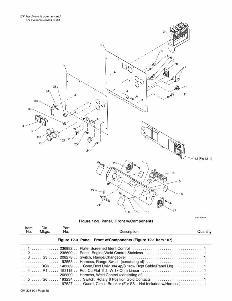
OM-228 921 Page 68
� Hardware is common andnot available unless listed.
804 700-B
31
29
28
30
27
22
21
23
24
25
26
20
32
34
33
35
1
2
13
19 18 17
16
15
14
56
8
11
12 (Fig 12−4)
79
10
4
3
Figure 12-3. Panel, Front w/Components
DescriptionPartNo.
Dia.Mkgs.
ItemNo.
Figure 12-3. Panel, Front w/Components (Figure 12-1 Item 107)
Quantity
1 236982 Plate, Screened Ident Control 1. . . . . . . . . . . . . . . . . . . . . . . . . . . . . . . . . . . . . . . . . . . . . . . . . . . . . . . 2 236609 Panel, Engine/Weld Control Stainless 1. . . . . . . . . . . . . . . . . . . . . . . . . . . . . . . . . . . . . . . . . . . . . . . . 3 S3 208278 Switch, Range/Changeover 1. . . . . . . . . . . . . . . . . . . . . . . . . . . . . . . . . . . . . . . . . . . . . . . . . . . . .
192558 Harness, Range Switch (consisting of) 1. . . . . . . . . . . . . . . . . . . . . . . . . . . . . . . . . . . . . . . . . . . . . . . . . . . RC6 148389 Conn,Rect Univ 084 4p/S 1row Rcpt Cable/Panel Lkg 1. . . . . . . . . . . . . . . . . . . . . . . . . . . . . . . .
4 R1 193118 Pot, Cp Flat 1t 2. W 1k Ohm Linear 1. . . . . . . . . . . . . . . . . . . . . . . . . . . . . . . . . . . . . . . . . . . . . . 206809 Harness, Weld Control (consisting of) 1. . . . . . . . . . . . . . . . . . . . . . . . . . . . . . . . . . . . . . . . . . . . . . . . . . . .
5 S6 193234 Switch, Rotary 6 Position Gold Contacts 1. . . . . . . . . . . . . . . . . . . . . . . . . . . . . . . . . . . . . . . . . . 197527 Guard, Circuit Breaker (For S6 − Not Included w/Harness) 1. . . . . . . . . . . . . . . . . . . . . . . . . . . . . . . . . .

OM-228 921 Page 69
DescriptionPartNo.
Dia.Mkgs.
ItemNo.
Figure 12-3. Panel, Front w/Components (Continued)
Quantity
6 S5 011609 Switch, Tgl Spdt 15a 125vac On−none−on Spd Term Chr 1. . . . . . . . . . . . . . . . . . . . . . . . . . . . PLG9 193183 Conn, Rect Cinch 18 Pin 1. . . . . . . . . . . . . . . . . . . . . . . . . . . . . . . . . . . . . . . . . . . . . . . . . . . . . . . . .
196603 Seal, Switch 6 Position Rotary .250 Shaft 1. . . . . . . . . . . . . . . . . . . . . . . . . . . . . . . . . . . . . . . . . . . . . . . . PLG14 141450 Conn, Rect Metrmate 10skt 1row Plug Cable Lkg 1. . . . . . . . . . . . . . . . . . . . . . . . . . . . . . . . . .
164617 Clip, Wiring Straight 2. . . . . . . . . . . . . . . . . . . . . . . . . . . . . . . . . . . . . . . . . . . . . . . . . . . . . . . . . . . . . . . . . . . RC10 150316 Conn, Rect Univ 039 6p/S 3row Plug Cable Lkg 1. . . . . . . . . . . . . . . . . . . . . . . . . . . . . . . . . . . . .
7 CB5 139266 Supplementary Protector, Man Reset 1p 15a 250vac 1. . . . . . . . . . . . . . . . . . . . . . . . . . . . . CB13 139266 Supplementary Protector, Man Reset 1p 15a 250vac 1. . . . . . . . . . . . . . . . . . . . . . . . . . . . . . . .
8 202209 Spacer, Nylon 2. . . . . . . . . . . . . . . . . . . . . . . . . . . . . . . . . . . . . . . . . . . . . . . . . . . . . . . . . . . . . . . . . . . . . . 9 PC6 192995 Circuit Card Assy, Connector/Receptacle 1. . . . . . . . . . . . . . . . . . . . . . . . . . . . . . . . . . . . . . .
10 S1 207720 Switch, Ignition 3 Position (Mom−off−mom) W/Handle 1. . . . . . . . . . . . . . . . . . . . . . . . . . . . . . 11 S7 199691 Switch, Tgl Spdt 6a 125vac On−none−mc Spd Term (included in . . . . . . . . . . . . . . .
engine harness, see Figure 12-2) 1. . . . . . . . . . . . . . . . . . . . . . . . . . . . . . . . . . . . . . . . . . . . . . . . . . . . . . . . . . . . . . . . 12 Figure 12-4 Auxiliary Power Panel, High KVA 1. . . . . . . . . . . . . . . . . . . . . . . . . . . . . . . . . . . . . . . . . . . . . . . . . 13 ♦196073 Label, Do Not Switch While Welding 1. . . . . . . . . . . . . . . . . . . . . . . . . . . . . . . . . . . . . . . . . . . . . . . . 14 ♦220491 Switch, Polarity/AC 1. . . . . . . . . . . . . . . . . . . . . . . . . . . . . . . . . . . . . . . . . . . . . . . . . . . . . . . . . . . . . . . 14 ♦195825 Switch, Polarity 1. . . . . . . . . . . . . . . . . . . . . . . . . . . . . . . . . . . . . . . . . . . . . . . . . . . . . . . . . . . . . . . . . . 15 199303 Panel, Mtg Terminal Power Output Stainless 1. . . . . . . . . . . . . . . . . . . . . . . . . . . . . . . . . . . . . . . . . . 16 PC4, PC5 189744 Circuit Card Assy, Filter Hf 2. . . . . . . . . . . . . . . . . . . . . . . . . . . . . . . . . . . . . . . . . . . . . . . . 17 NEGATIVE 039046 Terminal, Pwr Output Black 1. . . . . . . . . . . . . . . . . . . . . . . . . . . . . . . . . . . . . . . . . . . . . 18 134201 Stand−off Support, Pc Card .312/.375w/Post&lock .43 8. . . . . . . . . . . . . . . . . . . . . . . . . . . . . . . . . . 19 181169 Spacer, Output Stud 2. . . . . . . . . . . . . . . . . . . . . . . . . . . . . . . . . . . . . . . . . . . . . . . . . . . . . . . . . . . . . . . 20 186621 Boot, Generic Output Stud 2. . . . . . . . . . . . . . . . . . . . . . . . . . . . . . . . . . . . . . . . . . . . . . . . . . . . . . . . . . 21 ♦059777 Handle, Switch 1. . . . . . . . . . . . . . . . . . . . . . . . . . . . . . . . . . . . . . . . . . . . . . . . . . . . . . . . . . . . . . . . . . . 22 ♦010647 Pin, Spring cs .156 x 1.250 1. . . . . . . . . . . . . . . . . . . . . . . . . . . . . . . . . . . . . . . . . . . . . . . . . . . . . . . . 23 POSITIVE 039047 Terminal, Pwr Output Red 1. . . . . . . . . . . . . . . . . . . . . . . . . . . . . . . . . . . . . . . . . . . . . . . . 24 021385 Boot, Toggle Switch Lever 2. . . . . . . . . . . . . . . . . . . . . . . . . . . . . . . . . . . . . . . . . . . . . . . . . . . . . . . . . . 25 190323 Boot, Circuit Breaker Clear Hex Nut 3. . . . . . . . . . . . . . . . . . . . . . . . . . . . . . . . . . . . . . . . . . . . . . . . . . 26 170391 Conn, Circ Ms Protective Cap Size 20 Nylon 1. . . . . . . . . . . . . . . . . . . . . . . . . . . . . . . . . . . . . . . . . . 27 FUEL/HM 233095 Gauge, Fuel Elec/Hour Meter 1. . . . . . . . . . . . . . . . . . . . . . . . . . . . . . . . . . . . . . . . . . . . . . 28 AM 118060 Meter, Amp Dc 60−0−60 2.250 Dia High Profile Stainl 1. . . . . . . . . . . . . . . . . . . . . . . . . . . . . . . 29 TEMP 193229 Gauge, Coolant Temp 0− 300 Deg F Electric Switch 1. . . . . . . . . . . . . . . . . . . . . . . . . . . . . 30 ♦164873 Meter, Weld Amps 1. . . . . . . . . . . . . . . . . . . . . . . . . . . . . . . . . . . . . . . . . . . . . . . . . . . . . . . . . . . . . . . . 31 ♦164874 Meter, Weld Volts 1. . . . . . . . . . . . . . . . . . . . . . . . . . . . . . . . . . . . . . . . . . . . . . . . . . . . . . . . . . . . . . . . 32 097922 Knob, Pointer .875 Dia X .250 Id W/Set Screwsplstc 1. . . . . . . . . . . . . . . . . . . . . . . . . . . . . . . . . . . . 33 189161 Handle, Switch Range 1. . . . . . . . . . . . . . . . . . . . . . . . . . . . . . . . . . . . . . . . . . . . . . . . . . . . . . . . . . . . . . 34 010647 Pin, Spring Cs .156 X 1.250 1. . . . . . . . . . . . . . . . . . . . . . . . . . . . . . . . . . . . . . . . . . . . . . . . . . . . . . . . . 35 097924 Knob, Pointer 1.625 Dia X .250 Id W/Set Screwsplstc 1. . . . . . . . . . . . . . . . . . . . . . . . . . . . . . . . . . .
215207 Harness, Unit Weld Control − CV (consisting of) 1. . . . . . . . . . . . . . . . . . . . . . . . . . . . . . . . . . . . . . . . . . . PLG6 114063 Conn, Rect Univ 084 4p/S 1row Plug Cable Lkg 1. . . . . . . . . . . . . . . . . . . . . . . . . . . . . . . . . . . . . PLG8 193184 Conn, Rect Cinch 30 Pin 1. . . . . . . . . . . . . . . . . . . . . . . . . . . . . . . . . . . . . . . . . . . . . . . . . . . . . . . . .
PLG13 147992 Conn, Rect Univ 039 10p/S 2row Plug Cable Lkg 1. . . . . . . . . . . . . . . . . . . . . . . . . . . . . . . . . . PLG3 158465 Conn, Rect Univ 084 12p/S 3row Plug Cable Lkg 1. . . . . . . . . . . . . . . . . . . . . . . . . . . . . . . . . . . .
088731 Bushing, Snap−in Nyl .375 Id X .500 Mtg Hole 1. . . . . . . . . . . . . . . . . . . . . . . . . . . . . . . . . . . . . . . . . . . . 135873 Clip, Conduit Convoluted 1/2 In 6.35mm Mtg Hole 3. . . . . . . . . . . . . . . . . . . . . . . . . . . . . . . . . . . . . . . . . 187654 Seal, Wire Univ 12p/S 3row 1. . . . . . . . . . . . . . . . . . . . . . . . . . . . . . . . . . . . . . . . . . . . . . . . . . . . . . . . . . . . 196602 Plug, Cavity 18, 30 Position Cinch Connector 7. . . . . . . . . . . . . . . . . . . . . . . . . . . . . . . . . . . . . . . . . . . . . 024103 Blank, Snap−in Nyl .750 Mtg Hole Black 1. . . . . . . . . . . . . . . . . . . . . . . . . . . . . . . . . . . . . . . . . . . . . . . . . 120304 Blank, Snap−in Nyl .250 Mtg Hole Black 2. . . . . . . . . . . . . . . . . . . . . . . . . . . . . . . . . . . . . . . . . . . . . . . . .
♦Optional
+ When ordering a component originally displaying a precautionary label, the label should also be ordered. Orderlabel individually or as part of label kit 210 738.
To maintain the factory original performance of your equipment, use only Manufacturer’s SuggestedReplacement Parts. Model and serial number required when ordering parts from your local distributor.

OM-228 921 Page 70
� Hardware is common andnot available unless listed.
19
1
16
14
1715
20 6
11
7
1213
9
10
8
4
32
5
18
Figure 12-4. Auxiliary Power Panel, High KVA
DescriptionPartNo.
Dia.Mkgs.
ItemNo.
Figure 12-4. Auxiliary Power Panel, High KVA (Figure 12-3 Item 12)
Quantity
1 CB1 201083 Supplementary Protector, Man Reset 2p 20a 250vac 1. . . . . . . . . . . . . . . . . . . . . . . . . . . . . 201553 Clip, Retaining Circuit Breaker 1. . . . . . . . . . . . . . . . . . . . . . . . . . . . . . . . . . . . . . . . . . . . . . . . . . . . . . . . . . 201109 Harness, Receptacle Auxillary Power (consisting of) 1. . . . . . . . . . . . . . . . . . . . . . . . . . . . . . . . . . . . . . .
2 CB2 093996 Supplementary Pro, Man Reset 1p 20a 250vac Frict 1. . . . . . . . . . . . . . . . . . . . . . . . . . . . . 3 GFCI-1 151981 Rcpt, Str Dx Grd 2p3w 15/20a 125v *5−20r Gfi 1. . . . . . . . . . . . . . . . . . . . . . . . . . . . . . . . . 4 RC1 147632 Rcpt, Tw Lk Grd 2p3w 30a 250v *L6−30r 1. . . . . . . . . . . . . . . . . . . . . . . . . . . . . . . . . . . . . . . .
010146 Clamp, Nyl .625 Clamp Dia X.500 Wide .203 Mtg Hole 2. . . . . . . . . . . . . . . . . . . . . . . . . . . . . . . . . . . . . 5 RC5 182954 Rcpt,Str 3p4w 50a 125/250v Flush Mtg *14−50 1. . . . . . . . . . . . . . . . . . . . . . . . . . . . . . . . . . 6 025248 Stand−off,Insul .250−20 X 1.250 Lg X .437 Thd 1. . . . . . . . . . . . . . . . . . . . . . . . . . . . . . . . . . . . . . . . 7 604102 Conn,Clamp Cable 1.000 1. . . . . . . . . . . . . . . . . . . . . . . . . . . . . . . . . . . . . . . . . . . . . . . . . . . . . . . . . . . 8 197527 Guard,Circuit Breaker 1. . . . . . . . . . . . . . . . . . . . . . . . . . . . . . . . . . . . . . . . . . . . . . . . . . . . . . . . . . . . . . 9 197363 Terminal,Ring Tng Screw Clamp 14ga−6ga 3. . . . . . . . . . . . . . . . . . . . . . . . . . . . . . . . . . . . . . . . . . . .
10 CB7 214926 Supplementary Protector, Man Reset 3p 50a 250vac 1. . . . . . . . . . . . . . . . . . . . . . . . . . . . 11 +215363 Panel,Aux Power W/High Kva 1. . . . . . . . . . . . . . . . . . . . . . . . . . . . . . . . . . . . . . . . . . . . . . . . . . . . . . 12 214927 Boot,Circuit Breaker 1 Pole 1. . . . . . . . . . . . . . . . . . . . . . . . . . . . . . . . . . . . . . . . . . . . . . . . . . . . . . . . . 13 197508 Plug,Protective 1. . . . . . . . . . . . . . . . . . . . . . . . . . . . . . . . . . . . . . . . . . . . . . . . . . . . . . . . . . . . . . . . . . . . 14 077440 Bushing,Conduit 1 In 1. . . . . . . . . . . . . . . . . . . . . . . . . . . . . . . . . . . . . . . . . . . . . . . . . . . . . . . . . . . . . . . 15 601836 Nut, 250−20 .50hex .19h Brs 3. . . . . . . . . . . . . . . . . . . . . . . . . . . . . . . . . . . . . . . . . . . . . . . . . . . . . . . . 16 083030 Stud,Brs .250−20 X 1.750 W/Hex Collar 1. . . . . . . . . . . . . . . . . . . . . . . . . . . . . . . . . . . . . . . . . . . . . . 17 209056 Cover,Receptacle W/Gasket 3. . . . . . . . . . . . . . . . . . . . . . . . . . . . . . . . . . . . . . . . . . . . . . . . . . . . . . . . 18 127011 Rivet,Al .187 Dia X .251−.375 Grip Blind Domed Hd 12. . . . . . . . . . . . . . . . . . . . . . . . . . . . . . . . . . . . 19 197399 Label, Warning 3Ph Generator Power 1. . . . . . . . . . . . . . . . . . . . . . . . . . . . . . . . . . . . . . . . . . . . . . . . . 20 206795 Boot,Circuit Breaker Clear Hex Nut 1. . . . . . . . . . . . . . . . . . . . . . . . . . . . . . . . . . . . . . . . . . . . . . . . . . .
+ When ordering a component originally displaying a precautionary label, the label should also be ordered. Orderlabel individually or as part of label kit 210 738.
To maintain the factory original performance of your equipment, use only Manufacturer’s SuggestedReplacement Parts. Model and serial number required when ordering parts from your local distributor.
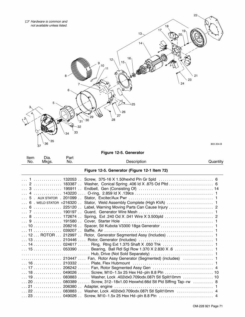
OM-228 921 Page 71
� Hardware is common andnot available unless listed.
803 204-B
5
6
8
9
25
3031
32
3334
7
2728
29
3736
35
1 2
4
3
26
1011
22
12
1920
1817
14
1615
13
2123
24
Figure 12-5. Generator
DescriptionPartNo.
Dia.Mkgs.
ItemNo.
Figure 12-5. Generator (Figure 12-1 Item 72)
Quantity
1 132053 Screw, 375-16 X 1.50hexhd Pln Gr 5pld 6. . . . . . . . . . . . . . . . . . . . . . . . . . . . . . . . . . . . . . . . . . . . . . 2 183387 Washer, Conical Spring .406 Id X .875 Od Pltd 6. . . . . . . . . . . . . . . . . . . . . . . . . . . . . . . . . . . . . . . . . 3 195911 Endbell, Gen (Consisting Of) 14. . . . . . . . . . . . . . . . . . . . . . . . . . . . . . . . . . . . . . . . . . . . . . . . . . . . . . . . 4 143220 O-ring, 2.859 Id X .139cs 1. . . . . . . . . . . . . . . . . . . . . . . . . . . . . . . . . . . . . . . . . . . . . . . . . . . . . . . . . . . . 5 AUX STATOR 201099 Stator, Exciter/Aux Pwr 1. . . . . . . . . . . . . . . . . . . . . . . . . . . . . . . . . . . . . . . . . . . . . . . . . 6 WELD STATOR +216320 Stator, Weld Assembly Complete (High KVA) 1. . . . . . . . . . . . . . . . . . . . . . . . . . . . . 6 225120 Label, Warning Moving Parts Can Cause Injury 2. . . . . . . . . . . . . . . . . . . . . . . . . . . . . . . . . . . . . . . . . 7 190197 Guard, Generator Wire Mesh 1. . . . . . . . . . . . . . . . . . . . . . . . . . . . . . . . . . . . . . . . . . . . . . . . . . . . . . . . 8 172674 Spring, Ext .240 Od X .041 Wire X 3.500pld 2. . . . . . . . . . . . . . . . . . . . . . . . . . . . . . . . . . . . . . . . . . . 9 191580 Cover, Starter Hole 1. . . . . . . . . . . . . . . . . . . . . . . . . . . . . . . . . . . . . . . . . . . . . . . . . . . . . . . . . . . . . . . .
10 208216 Spacer, Stl Kubota V3300 18ga Generator 1. . . . . . . . . . . . . . . . . . . . . . . . . . . . . . . . . . . . . . . . . . . . . 11 039207 Baffle, Air 1. . . . . . . . . . . . . . . . . . . . . . . . . . . . . . . . . . . . . . . . . . . . . . . . . . . . . . . . . . . . . . . . . . . . . . . . . 12 ROTOR 212997 Rotor, Generator Segmented Assy (Includes) 1. . . . . . . . . . . . . . . . . . . . . . . . . . . . . . . . . . 13 210446 Rotor, Generator (Includes) 1. . . . . . . . . . . . . . . . . . . . . . . . . . . . . . . . . . . . . . . . . . . . . . . . . . . . . . . . . . 14 024617 Ring, Rtng Ext 1.375 Shaft X .050 Thk 1. . . . . . . . . . . . . . . . . . . . . . . . . . . . . . . . . . . . . . . . . . . . . . . . 15 053390 Bearing, Ball Rdl Sgl Row 1.370 X 2.830 X .6 1. . . . . . . . . . . . . . . . . . . . . . . . . . . . . . . . . . . . . . . . . .
Hub, Drive (Not Sold Separately) 1. . . . . . . . . . . . . . . . . . . . . . . . . . . . . . . . . . . . . . . . . . . . . . . . . . . . . . . . . . . . . . . . . 210447 Fan, Rotor Assy Generator (Segmented) (includes) 1. . . . . . . . . . . . . . . . . . . . . . . . . . . . . . . . . . . . . . .
16 210332 Plate, Flex Hubmount 1. . . . . . . . . . . . . . . . . . . . . . . . . . . . . . . . . . . . . . . . . . . . . . . . . . . . . . . . . . . . . . . 17 206242 Fan, Rotor Segmented Assy Gen 4. . . . . . . . . . . . . . . . . . . . . . . . . . . . . . . . . . . . . . . . . . . . . . . . . . . . . 18 049026 Screw, M10−1.5x 25 Hex Hd−pln 8.8 Pln 10. . . . . . . . . . . . . . . . . . . . . . . . . . . . . . . . . . . . . . . . . . . . . . . 19 083883 Washer, Lock .402idx0.709odx.087t Stl Split10mm 10. . . . . . . . . . . . . . . . . . . . . . . . . . . . . . . . . . . . . . 20 080389 Screw, 312−18x1.00 Hexwhd.66d Stl Pld Slffmg Tap−rw 8. . . . . . . . . . . . . . . . . . . . . . . . . . . . . . . . . 21 206380 Adapter, engine 1. . . . . . . . . . . . . . . . . . . . . . . . . . . . . . . . . . . . . . . . . . . . . . . . . . . . . . . . . . . . . . . . . . . . 22 083883 Washer, Lock .402idx0.709odx.087t Stl Split10mm 4. . . . . . . . . . . . . . . . . . . . . . . . . . . . . . . . . . . . . 23 049026 Screw, M10−1.5x 25 Hex Hd−pln 8.8 Pln 4. . . . . . . . . . . . . . . . . . . . . . . . . . . . . . . . . . . . . . . . . . . . . .

OM-228 921 Page 72
DescriptionPartNo.
Dia.Mkgs.
ItemNo.
Figure 12-5. Generator (Continued)
Quantity
24 191579 Cover, Starter Hole 2. . . . . . . . . . . . . . . . . . . . . . . . . . . . . . . . . . . . . . . . . . . . . . . . . . . . . . . . . . . . . . . . 25 083883 Washer, Lock .402idx0.709odx.087t Stl Split10mm 6. . . . . . . . . . . . . . . . . . . . . . . . . . . . . . . . . . . . . 26 172555 Screw, M10-1.5 X 50hexhd Pln 8.8pld 6. . . . . . . . . . . . . . . . . . . . . . . . . . . . . . . . . . . . . . . . . . . . . . . . 27 602159 Screw, .312-18 X .75hexwhd 6. . . . . . . . . . . . . . . . . . . . . . . . . . . . . . . . . . . . . . . . . . . . . . . . . . . . . . . . 28 604950 Screw, .312-18 X 2.25hexhd Pln Gr 5pld 4. . . . . . . . . . . . . . . . . . . . . . . . . . . . . . . . . . . . . . . . . . . . . . 29 602211 Washer, Lock .318 Id X 0.586 4. . . . . . . . . . . . . . . . . . . . . . . . . . . . . . . . . . . . . . . . . . . . . . . . . . . . . . . 30 139341 Washer, Exciter 4. . . . . . . . . . . . . . . . . . . . . . . . . . . . . . . . . . . . . . . . . . . . . . . . . . . . . . . . . . . . . . . . . . . . 31 *190823 Brush, Contact 3. . . . . . . . . . . . . . . . . . . . . . . . . . . . . . . . . . . . . . . . . . . . . . . . . . . . . . . . . . . . . . . . . . . 32 208469 Clip, Spring 3. . . . . . . . . . . . . . . . . . . . . . . . . . . . . . . . . . . . . . . . . . . . . . . . . . . . . . . . . . . . . . . . . . . . . . . 33 189142 Brushholder Assembly, Gen 1. . . . . . . . . . . . . . . . . . . . . . . . . . . . . . . . . . . . . . . . . . . . . . . . . . . . . . . . . 34 602242 Washer, Flat .375idx0.875odx.083t Stl Pld 2. . . . . . . . . . . . . . . . . . . . . . . . . . . . . . . . . . . . . . . . . . . . 35 602211 Washer, Lock .318idx0.586odx.078t Stl Pld Split.312 2. . . . . . . . . . . . . . . . . . . . . . . . . . . . . . . . . . . . 36 604534 Screw, 312−18x1.25 Hex Hd−pln Gr5 Pld 2. . . . . . . . . . . . . . . . . . . . . . . . . . . . . . . . . . . . . . . . . . . . .
190259 Harness, Brush (Consisting Of) 1. . . . . . . . . . . . . . . . . . . . . . . . . . . . . . . . . . . . . . . . . . . . . . . . . . . . . . . . . PLG1 168071 Connector, (Kit) Rect Univ 084 9p/S 3 Row Plug Cable Lkg 1. . . . . . . . . . . . . . . . . . . . . . . . . . .
187651 Seal, Wire Univ 9p/S 3 Row 1. . . . . . . . . . . . . . . . . . . . . . . . . . . . . . . . . . . . . . . . . . . . . . . . . . . . . . . . . . . .
+ When ordering a component originally displaying a precautionary label, the label should also be ordered. Orderlabel individually or as part of label kit 210 738.
*Recommended Spare Parts.
♦Optional
To maintain the factory original performance of your equipment, use only Manufacturer’s SuggestedReplacement Parts. Model and serial number required when ordering parts from your local distributor.

OM-228 921 Page 73
� Hardware is common andnot available unless listed.
802 279-A
1
2
3
4
6
5
7
8
9
Figure 12-6. Main Rectifier Assembly
DescriptionPartNo.
Dia.Mkgs.
ItemNo.
Figure 12-6. Main Rectifier Assembly (Figure 12-1 Item 109)
Quantity
SR3 215910 Rectifier, Environmental (Consisting Of) 1. . . . . . . . . . . . . . . . . . . . . . . . . . . . . . . . . . . . . . . . . . . . 1 188137 Connection Board, Rectifier Ac 1. . . . . . . . . . . . . . . . . . . . . . . . . . . . . . . . . . . . . . . . . . . . . . . . . . . . . . . 2 188517 Bus Bar, Connection Board 3. . . . . . . . . . . . . . . . . . . . . . . . . . . . . . . . . . . . . . . . . . . . . . . . . . . . . . . . . . 3 188135 Enclosure, Rectifier 2. . . . . . . . . . . . . . . . . . . . . . . . . . . . . . . . . . . . . . . . . . . . . . . . . . . . . . . . . . . . . . . . 4 134201 Stand-off, Support 3. . . . . . . . . . . . . . . . . . . . . . . . . . . . . . . . . . . . . . . . . . . . . . . . . . . . . . . . . . . . . . . . . . 5 PC3 215755 Circuit Card Assembly, Protection 1. . . . . . . . . . . . . . . . . . . . . . . . . . . . . . . . . . . . . . . . . . . . . . 6 188136 Insulator, Heat Sink 8. . . . . . . . . . . . . . . . . . . . . . . . . . . . . . . . . . . . . . . . . . . . . . . . . . . . . . . . . . . . . . . . 7 188493 Heat Sink, Rectifier Al 2. . . . . . . . . . . . . . . . . . . . . . . . . . . . . . . . . . . . . . . . . . . . . . . . . . . . . . . . . . . . . . 8 D3, D5, D7 208334 Diode, rect 275A 300V SP 3. . . . . . . . . . . . . . . . . . . . . . . . . . . . . . . . . . . . . . . . . . . . . . 9 D2, D4, D6 208335 Diode, rect 275A 300V RP 3. . . . . . . . . . . . . . . . . . . . . . . . . . . . . . . . . . . . . . . . . . . . . .
To maintain the factory original performance of your equipment, use only Manufacturer’s SuggestedReplacement Parts. Model and serial number required when ordering parts from your local distributor.Base Group

OM-228 921 Page 74
Notes

Effective January 1, 2009(Equipment with a serial number preface of LK or newer)
This limited warranty supersedes all previous manufacturerswarranties and is exclusive with no other guarantees orwarranties expressed or implied.
LIMITED WARRANTY − Subject to the terms and conditionsbelow, warrants to its original retail purchaser that newequipment sold after the effective date of this limited warranty isfree of defects in material and workmanship at the time it isshipped from factory. THIS WARRANTY IS EXPRESSLY INLIEU OF ALL OTHER WARRANTIES, EXPRESS ORIMPLIED, INCLUDING THE WARRANTIES OFMERCHANTABILITY AND FITNESS.
Within the warranty periods listed below, manufacturer willrepair or replace any warranted parts or components that faildue to such defects in material or workmanship. Manufacturermust be notified in writing within thirty (30) days of such defect orfailure, at which time manufacturer will provide instructions onthe warranty claim procedures to be followed.
Manufacturer shall honor warranty claims on warrantedequipment listed below in the event of such a failure within thewarranty time periods. All warranty time periods start on thedelivery date of the equipment to the original end-userpurchaser, and not to exceed one year after the equipment isshipped to the distributor.
1. 5 Years Parts — 3 Years Labor
* Original main power rectifiers only to include SCRs,diodes, and discrete rectifier modules
2. 3 Years — Parts and Labor
* Transformer/Rectifier Power Sources* Plasma Arc Cutting Power Sources* Process Controllers* Semi-Automatic and Automatic Wire Feeders* Inverter Power Sources (Unless Otherwise Stated)* Water Coolant Systems (Integrated)* Engine Driven Welding Generators
(NOTE: Engines are warranted separately by theengine manufacturer.)
3. 1 Year — Parts and Labor Unless Specified
* Motor Driven Guns (w/exception of SpoolmateSpoolguns)
* Positioners and Controllers* Automatic Motion Devices* RFCS Foot Controls* Induction Heating Power Sources, Coolers, and
Electronic Controls/Recorders* Water Coolant Systems (Non-Integrated)* Flowgauge and Flowmeter Regulators (No Labor)* HF Units* Grids* Spot Welders* Load Banks* Fume Extractors* Arc Stud Power Sources & Arc Stud Guns* Racks* Running Gear/Trailers* Plasma Cutting Torches (except APT & SAF
models)* Field Options
(NOTE: Field options are covered for the remainingwarranty period of the product they are installed in,or for a minimum of one year — whichever isgreater.)
* Bernard-Branded Mig Guns (No Labor)* Weldcraft-Branded TIG Torches (No Labor)* Subarc Wire Drive Assemblies
4. 6 Months — Batteries
5. 90 Days — Parts and Labor
* MIG Guns and Subarc (SAW) Guns
* Induction Heating Coils and Blankets, Cables, andNon-Electronic Controls
* APT & SAF Plasma Cutting Torches* Remote Controls* Accessory Kits* Replacement Parts (No Labor)* Spoolmate Spoolguns* Canvas Covers
Limited Warranty shall not apply to:
1. Consumable components; such as contact tips,cutting nozzles, contactors, relays, brushes, sliprings, or parts that fail due to normal wear.
2. Items furnished by manufacturer, but manufactured byothers, such as engines or trade accessories. These itemsare covered by the manufacturer’s warranty, if any.
3. Equipment that has been modified by any party other thanmanufacturer, or equipment that has been improperlyinstalled, improperly operated or misused based uponindustry standards, or equipment which has not hadreasonable and necessary maintenance, or equipmentwhich has been used for operation outside of thespecifications for the equipment.
MANUFACTURER’S PRODUCTS ARE INTENDED FORPURCHASE AND USE BY COMMERCIAL/INDUSTRIALUSERS AND PERSONS TRAINED AND EXPERIENCED INTHE USE AND MAINTENANCE OF WELDING EQUIPMENT.
In the event of a warranty claim covered by this warranty, theexclusive remedies shall be, at manufacturer’s option: (1)repair; or (2) replacement; or, where authorized in writing bymanufacturer in appropriate cases, (3) the reasonable cost ofrepair or replacement at an authorized service station; or (4)payment of or credit for the purchase price (less reasonabledepreciation based upon actual use) upon return of the goods atcustomer’s risk and expense. Manufacturer’s option of repair orreplacement will be F.O.B., Factory at Appleton, Wisconsin, orF.O.B. at an authorized service facility as determined bymanufacturer. Therefore no compensation or reimbursementfor transportation costs of any kind will be allowed.
TO THE EXTENT PERMITTED BY LAW, THE REMEDIESPROVIDED HEREIN ARE THE SOLE AND EXCLUSIVEREMEDIES. IN NO EVENT SHALL MANUFACTURER BELIABLE FOR DIRECT, INDIRECT, SPECIAL, INCIDENTAL ORCONSEQUENTIAL DAMAGES (INCLUDING LOSS OFPROFIT), WHETHER BASED ON CONTRACT, TORT ORANY OTHER LEGAL THEORY.
ANY EXPRESS WARRANTY NOT PROVIDED HEREIN ANDANY IMPLIED WARRANTY, GUARANTY ORREPRESENTATION AS TO PERFORMANCE, AND ANYREMEDY FOR BREACH OF CONTRACT TORT OR ANYOTHER LEGAL THEORY WHICH, BUT FOR THISPROVISION, MIGHT ARISE BY IMPLICATION, OPERATIONOF LAW, CUSTOM OF TRADE OR COURSE OF DEALING,INCLUDING ANY IMPLIED WARRANTY OFMERCHANTABILITY OR FITNESS FOR PARTICULARPURPOSE, WITH RESPECT TO ANY AND ALL EQUIPMENTFURNISHED BY MANUFACTURER IS EXCLUDED ANDDISCLAIMED BY MANUFACTURER.
Some states in the U.S.A. do not allow limitations of how long animplied warranty lasts, or the exclusion of incidental, indirect,special or consequential damages, so the above limitation orexclusion may not apply to you. This warranty provides specificlegal rights, and other rights may be available, but may varyfrom state to state.
In Canada, legislation in some provinces provides for certainadditional warranties or remedies other than as stated herein,and to the extent that they may not be waived, the limitations andexclusions set out above may not apply. This Limited Warrantyprovides specific legal rights, and other rights may be available,but may vary from province to province.
brand_warr 2009−01
Warranty

ORIGINAL INSTRUCTIONS − PRINTED IN USA 2009−01
Model Name Serial/Style Number
Purchase Date (Date which equipment was delivered to original customer.)
Distributor
Address
City
State Zip
Please complete and retain with your personal records.
Contact the Delivering Carrier for:
For assistance in filing or settling claims,contact your distributor and/or equipmentmanufacturer’s Transportation Department.
Owner’s Record
File a claim for loss or damage duringshipment.