oled product specification
TRANSCRIPT

www.usmicroproducts.com CONFIDENTIAL (800) 741-7755
OLED PRODUCT SPECIFICATION
PART NUMBER: USMP-P23601
DESCRIPTION:
ISSUE DATE APPROVED BY (Customer Use Only)
CHECKED BY PREPARED BY
PROPRIETARY NOTE:
THIS SPECIFICATION IS THE PROPERTY OF US MICRO PRODUCTS AND SHALL NOT BE REPRODUCED OR COPIED WITHOUT THE WRITTEN PERMISSION OF US MICRO PRODUCTS AND MUST BE RETURNED TO
US MICRO PRODUCTS UPON ITS REQUEST.
1.0", 128 x 32, White,LD7032, TAB
Manufactured by:

- 1 - REV.: X01 2008/12/22This document contains confidential and proprietary information. Neither it nor the informationcontained herein shall be disclosed to others or duplicated or used for others without the expresswritten consent of RiTdisplay.
Preliminary SpecificationPRODUCT NAME: RGS10128032WR006PRODUCT NO.: 9923601000
CUSTOMER
APPROVED BY
DATE:
RITDISPLAY CORP. APPROVED
CO
NFID
EN
TIAL
www.usmicroproducts.com (800) 741-7755

- 2 - REV.: X01 2008/12/22This document contains confidential and proprietary information. Neither it nor the informationcontained herein shall be disclosed to others or duplicated or used for others without the expresswritten consent of RiTdisplay.
REVISION RECORDREV. REVISION DESCRIPTION REV. DATE REMARKX01 INITIAL RELEASE 2008. 12. 22
CO
NFID
EN
TIAL
www.usmicroproducts.com (800) 741-7755
- 3 - REV.: X01 2008/12/22This document contains confidential and proprietary information. Neither it nor the informationcontained herein shall be disclosed to others or duplicated or used for others without the expresswritten consent of RiTdisplay.
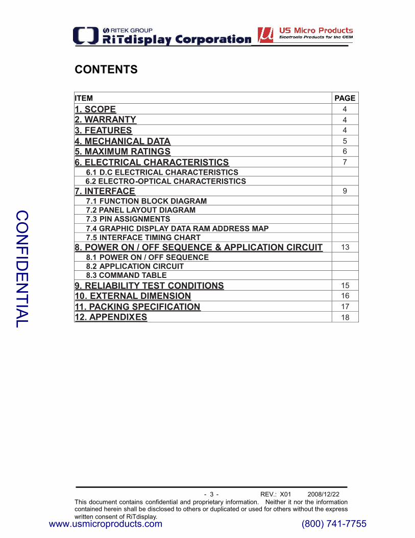
CONTENTS
ITEM PAGE1. SCOPE 42. WARRANTY 43. FEATURES 44. MECHANICAL DATA 55. MAXIMUM RATINGS 66. ELECTRICAL CHARACTERISTICS 7
6.1 D.C ELECTRICAL CHARACTERISTICS6.2 ELECTRO-OPTICAL CHARACTERISTICS
7. INTERFACE 97.1 FUNCTION BLOCK DIAGRAM7.2 PANEL LAYOUT DIAGRAM7.3 PIN ASSIGNMENTS7.4 GRAPHIC DISPLAY DATA RAM ADDRESS MAP7.5 INTERFACE TIMING CHART
8. POWER ON / OFF SEQUENCE & APPLICATION CIRCUIT 138.1 POWER ON / OFF SEQUENCE8.2 APPLICATION CIRCUIT8.3 COMMAND TABLE
9. RELIABILITY TEST CONDITIONS 1510. EXTERNAL DIMENSION 1611. PACKING SPECIFICATION 1712. APPENDIXES 18
CO
NFID
EN
TIAL
www.usmicroproducts.com (800) 741-7755

- 4 - REV.: X01 2008/12/22This document contains confidential and proprietary information. Neither it nor the informationcontained herein shall be disclosed to others or duplicated or used for others without the expresswritten consent of RiTdisplay.
1. SCOPEThe purpose of this specification is to define the general provisions and qualityrequirements that apply to the supply of display cells manufactured byRiTdisplay. This document, together with the Module Assembly Drawing, is thehighest-level specification for this product. It describes the product, identifiessupporting documents and contains specifications.
2. WARRANTYRiTdisplay warrants that the products delivered pursuant to this specification (ororder) will conform to the agreed specifications for twelve (12) months from theshipping date ("Warranty Period"). RiTdisplay is obligated to repair or replacethe products which are found to be defective or inconsistent with thespecifications during the Warranty Period without charge, on condition that theproducts are stored or used as the conditions specified in the specifications.Nevertheless, RiTdisplay is not obligated to repair or replace the productswithout charge if the defects or inconsistency are caused by the force majeureor the reckless behaviors of the customer.After the Warranty Period, all repairs or replacements of the products aresubject to charge.
3. FEATURESSmall molecular organic light emitting diode.Color : WhitePanel matrix : 128*32Driver IC : LD7032Excellent quick response time.Extremely thin thickness for best mechanism design : 1.21mmHigh contrast : 2000:1Wide viewing angle : 160�8080 or 6800 series parallel interface, Serial Peripheral Interface, I2CSerial Interface.Wide range of operating temperature : -40 to 70 °CAnti-glare polarizer.
CO
NFID
EN
TIAL
www.usmicroproducts.com (800) 741-7755
- 5 - REV.: X01 2008/12/22This document contains confidential and proprietary information. Neither it nor the informationcontained herein shall be disclosed to others or duplicated or used for others without the expresswritten consent of RiTdisplay.
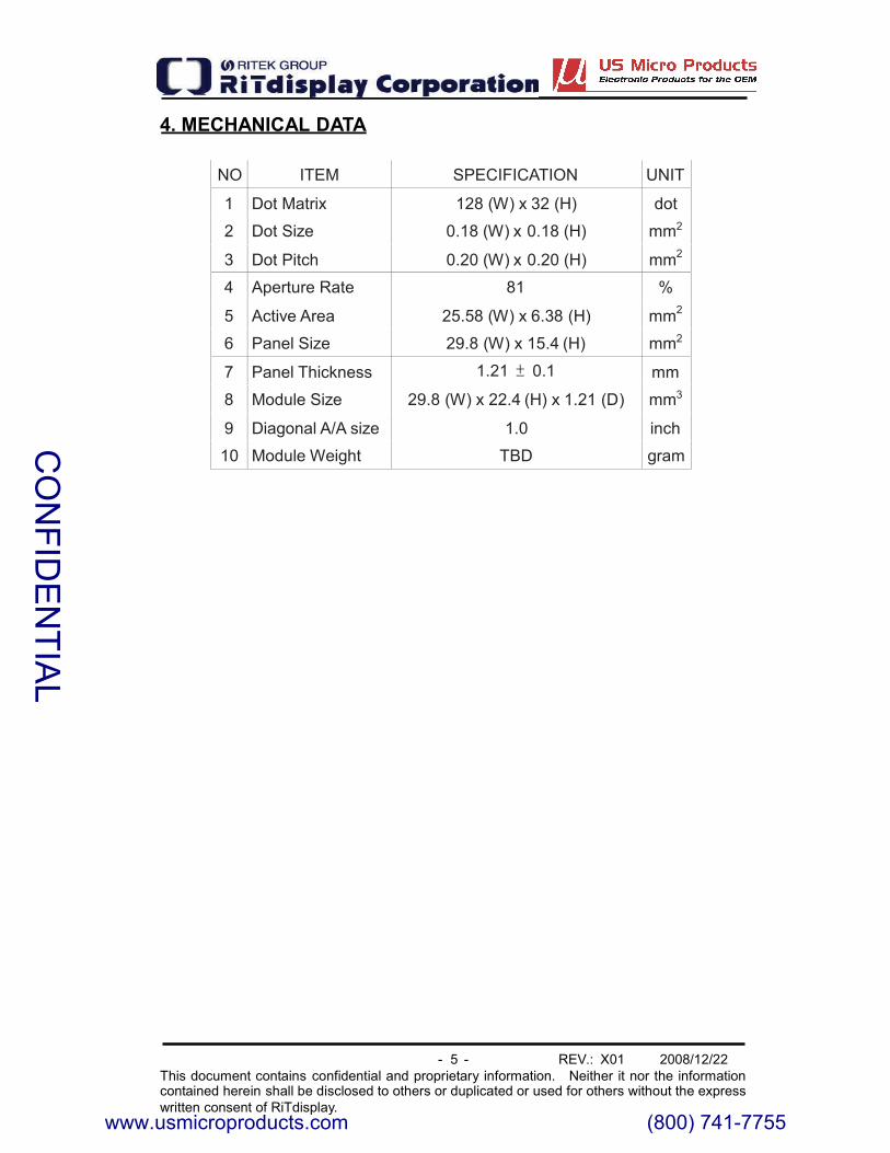
4. MECHANICAL DATA
NO ITEM SPECIFICATION UNIT
1 Dot Matrix 128 (W) x 32 (H) dot
2 Dot Size 0.18 (W) x 0.18 (H) mm2
3 Dot Pitch 0.20 (W) x 0.20 (H) mm2
4 Aperture Rate 81 %
5 Active Area 25.58 (W) x 6.38 (H) mm2
6 Panel Size 29.8 (W) x 15.4 (H) mm2
7 Panel Thickness 1.21 0.1 mm
8 Module Size 29.8 (W) x 22.4 (H) x 1.21 (D) mm3
9 Diagonal A/A size 1.0 inch
10 Module Weight TBD gram
CO
NFID
EN
TIAL
www.usmicroproducts.com (800) 741-7755
- 6 - REV.: X01 2008/12/22This document contains confidential and proprietary information. Neither it nor the informationcontained herein shall be disclosed to others or duplicated or used for others without the expresswritten consent of RiTdisplay.
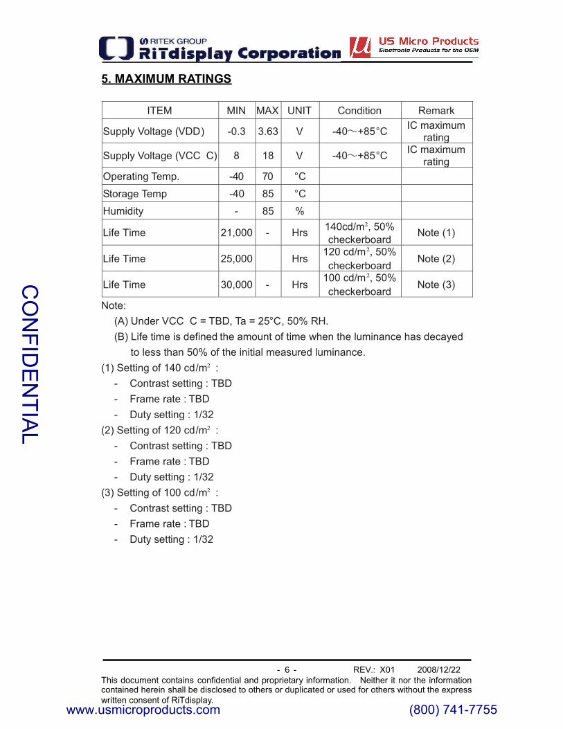
5. MAXIMUM RATINGS
ITEM MIN MAX UNIT Condition Remark
Supply Voltage (VDD) -0.3 3.63 V -40 +85°C IC maximumrating
Supply Voltage (VCC C) 8 18 V -40 +85°C IC maximumrating
Operating Temp. -40 70 °C
Storage Temp -40 85 °C
Humidity - 85 %
Life Time 21,000 - Hrs 140cd/m , 50%checkerboard
Note (1)
Life Time 25,000 Hrs120 cd/m , 50%checkerboard
Note (2)
Life Time 30,000 - Hrs100 cd/m , 50%checkerboard
Note (3)
Note:(A) Under VCC C = TBD, Ta = 25°C, 50% RH.(B) Life time is defined the amount of time when the luminance has decayed
to less than 50% of the initial measured luminance.(1) Setting of 140 cd/m :- Contrast setting : TBD- Frame rate : TBD- Duty setting : 1/32
(2) Setting of 120 cd/m :- Contrast setting : TBD- Frame rate : TBD- Duty setting : 1/32
(3) Setting of 100 cd/m :- Contrast setting : TBD- Frame rate : TBD- Duty setting : 1/32
CO
NFID
EN
TIAL
www.usmicroproducts.com (800) 741-7755

- 7 - REV.: X01 2008/12/22This document contains confidential and proprietary information. Neither it nor the informationcontained herein shall be disclosed to others or duplicated or used for others without the expresswritten consent of RiTdisplay.
6. ELECTRICAL CHARACTERISTICS
6.1 D.C ELECTRICAL CHARACTERISTICSSYMBOL PARAMETER CONDITIONS MIN TYP MAX UNIT
VDD Logic Power 1 1.65 2.8 3.5 V
VCC C OLED operatingvoltage TBD TBD TBD V
VIHHigh Logic InputLevel 0.8*VDD - VDD V
VILLow Logic InputLevel 0 - 0.2*VDD V
VOHHigh LogicOutput Level Iout -100uA 0.9*VDD - VDD V
VOLLow LogicOutput Level Iout 100uA 0 - 0.1*VDD V
IIL Input LeakageCurrent 1.0 +1.0 µA
Cptp1Output CurrentPin to PinEvenness *1)
Iout = 50uA -2.0 - +2.0
Calp1 Output CurrentEvenness *2) Iout = 50uA -4.0 - +4.0
Calp2 Output CurrentEvenness *4) Iout = 50uA TBD - TBD
Cchip1Output CurrentAbsoluteCorrectness *3)
Iout = 50uA 6.0 - +6.0
NOTICE:
*1) (Ik I k+1)/ Iavg : (k = 0 to 127 ), Iavg = ( Ik ) / 127 : (k = 0 to 127)
*2) (Imax Iavg / Iavg , (Imin Iavg ) / Iavg , Iavg = ( Ik ) / 127 : ( k = 0 to 127 )
*3) (Iavg Iref(SPEC)) / Iref(SPEC)
*4) Area Current Deviation at 1chip.
CO
NFID
EN
TIAL
www.usmicroproducts.com (800) 741-7755
- 8 - REV.: X01 2008/12/22This document contains confidential and proprietary information. Neither it nor the informationcontained herein shall be disclosed to others or duplicated or used for others without the expresswritten consent of RiTdisplay.
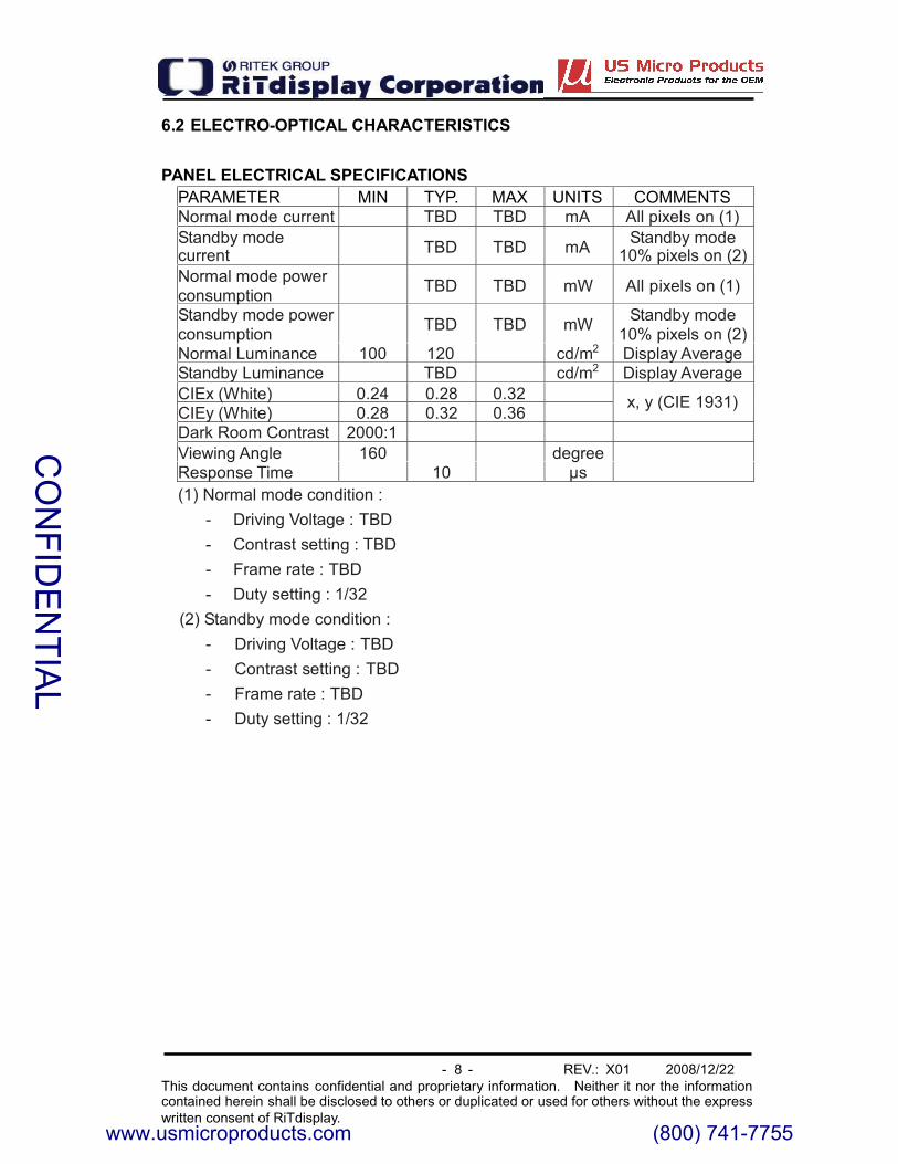
6.2 ELECTRO-OPTICAL CHARACTERISTICS
PANEL ELECTRICAL SPECIFICATIONSPARAMETER MIN TYP. MAX UNITS COMMENTSNormal mode current TBD TBD mA All pixels on (1)Standby modecurrent TBD TBD mA Standby mode
10% pixels on (2)Normal mode powerconsumption TBD TBD mW All pixels on (1)
Standby mode powerconsumption TBD TBD mW Standby mode
10% pixels on (2)Normal Luminance 100 120 cd/m2 Display AverageStandby Luminance TBD cd/m2 Display AverageCIEx (White) 0.24 0.28 0.32CIEy (White) 0.28 0.32 0.36
x, y (CIE 1931)
Dark Room Contrast 2000:1Viewing Angle 160 degreeResponse Time 10 �s(1) Normal mode condition :
- Driving Voltage : TBD- Contrast setting : TBD- Frame rate : TBD- Duty setting : 1/32
(2) Standby mode condition :- Driving Voltage : TBD- Contrast setting : TBD- Frame rate : TBD- Duty setting : 1/32
CO
NFID
EN
TIAL
www.usmicroproducts.com (800) 741-7755
- 9 - REV.: X01 2008/12/22This document contains confidential and proprietary information. Neither it nor the informationcontained herein shall be disclosed to others or duplicated or used for others without the expresswritten consent of RiTdisplay.
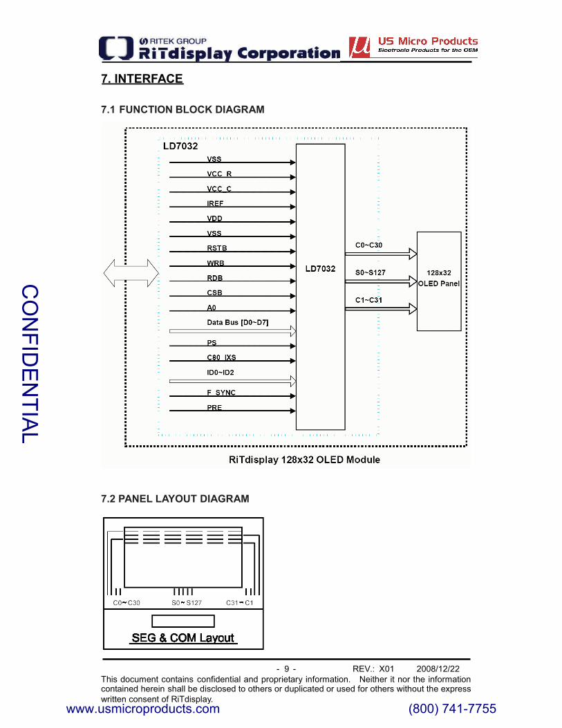
7. INTERFACE
7.1 FUNCTION BLOCK DIAGRAM
7.2 PANEL LAYOUT DIAGRAM
CO
NFID
EN
TIAL
www.usmicroproducts.com (800) 741-7755
- 10 - REV.: X01 2008/12/22This document contains confidential and proprietary information. Neither it nor the informationcontained herein shall be disclosed to others or duplicated or used for others without the expresswritten consent of RiTdisplay.
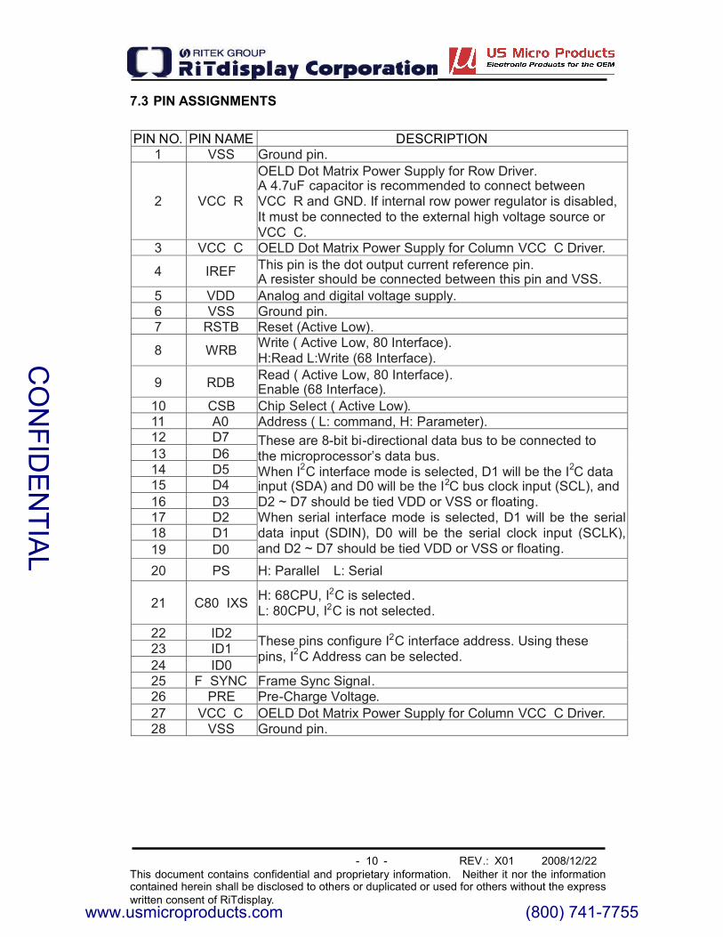
7.3 PIN ASSIGNMENTS
PIN NO. PIN NAME DESCRIPTION1 VSS Ground pin.
2 VCC R
OELD Dot Matrix Power Supply for Row Driver.A 4.7uF capacitor is recommended to connect betweenVCC R and GND. If internal row power regulator is disabled,It must be connected to the external high voltage source orVCC C.
3 VCC C OELD Dot Matrix Power Supply for Column VCC C Driver.
4 IREF This pin is the dot output current reference pin.A resister should be connected between this pin and VSS.
5 VDD Analog and digital voltage supply.6 VSS Ground pin.7 RSTB Reset (Active Low).
8 WRB Write ( Active Low, 80 Interface).H:Read L:Write (68 Interface).
9 RDB Read ( Active Low, 80 Interface).Enable (68 Interface).
10 CSB Chip Select ( Active Low).11 A0 Address ( L: command, H: Parameter).12 D713 D614 D515 D416 D317 D218 D119 D0
These are 8-bit bi-directional data bus to be connected tothe microprocessor’s data bus.When I2C interface mode is selected, D1 will be the I2C datainput (SDA) and D0 will be the I2C bus clock input (SCL), andD2 ~ D7 should be tied VDD or VSS or floating.When serial interface mode is selected, D1 will be the serialdata input (SDIN), D0 will be the serial clock input (SCLK),and D2 ~ D7 should be tied VDD or VSS or floating.
20 PS H: Parallel L: Serial
21 C80 IXS H: 68CPU, I2C is selected.L: 80CPU, I2C is not selected.
22 ID223 ID124 ID0
These pins configure I2C interface address. Using thesepins, I2C Address can be selected.
25 F SYNC Frame Sync Signal.26 PRE Pre-Charge Voltage.27 VCC C OELD Dot Matrix Power Supply for Column VCC C Driver.28 VSS Ground pin.
CO
NFID
EN
TIAL
www.usmicroproducts.com (800) 741-7755

- 11 - REV.: X01 2008/12/22This document contains confidential and proprietary information. Neither it nor the informationcontained herein shall be disclosed to others or duplicated or used for others without the expresswritten consent of RiTdisplay.
7.4 GRAPHIC DISPLAY DATA RAM ADDRESS MAP
CO
NFID
EN
TIAL
www.usmicroproducts.com (800) 741-7755
- 12 - REV.: X01 2008/12/22This document contains confidential and proprietary information. Neither it nor the informationcontained herein shall be disclosed to others or duplicated or used for others without the expresswritten consent of RiTdisplay.
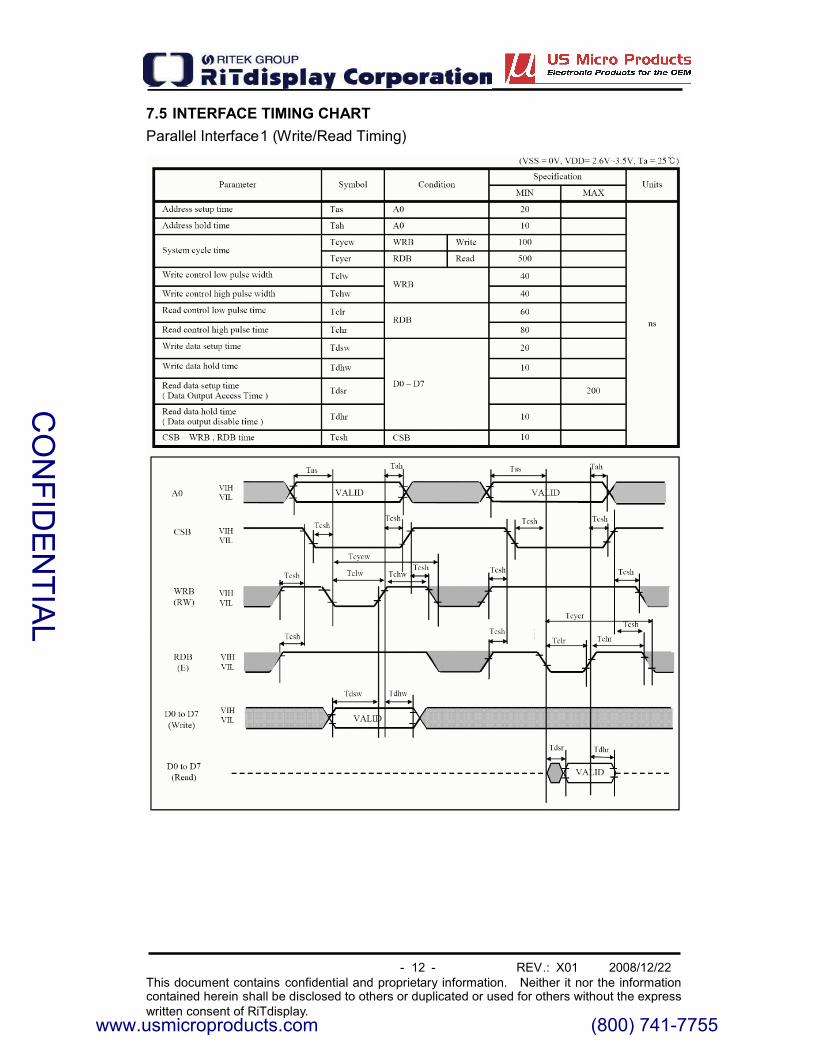
7.5 INTERFACE TIMING CHARTParallel Interface1 (Write/Read Timing)
CO
NFID
EN
TIAL
www.usmicroproducts.com (800) 741-7755

- 13 - REV.: X01 2008/12/22This document contains confidential and proprietary information. Neither it nor the informationcontained herein shall be disclosed to others or duplicated or used for others without the expresswritten consent of RiTdisplay.
Parallel Interface2 (Write/Read Timing)
CO
NFID
EN
TIAL
www.usmicroproducts.com (800) 741-7755

- 14 - REV.: X01 2008/12/22This document contains confidential and proprietary information. Neither it nor the informationcontained herein shall be disclosed to others or duplicated or used for others without the expresswritten consent of RiTdisplay.
8. POWER ON / OFF SEQUENCE & APPLICATION CIRCUIT8.1 POWER ON / OFF SEQUENCE
CO
NFID
EN
TIAL
www.usmicroproducts.com (800) 741-7755

- 15 - REV.: X01 2008/12/22This document contains confidential and proprietary information. Neither it nor the informationcontained herein shall be disclosed to others or duplicated or used for others without the expresswritten consent of RiTdisplay.
8.2 APPLICATION CIRCUIT
TBD
8.3 COMMAND TABLE
Refer to LD7032 IC Spec.
CO
NFID
EN
TIAL
www.usmicroproducts.com (800) 741-7755

- 16 - REV.: X01 2008/12/22This document contains confidential and proprietary information. Neither it nor the informationcontained herein shall be disclosed to others or duplicated or used for others without the expresswritten consent of RiTdisplay.
9. RELIABILITY TEST CONDITIONS
No. Items Specification Quantity
1 High temp.(Non-operation) 85°C, 240hrs 5
2 High temp. (Operation) 70°C, 120hrs 53 Low temp. (Operation) -40°C, 120hrs 5
4 High temp. / Highhumidity (Operation) 65°C, 90%RH, 120hrs 5
5 Thermal shock(Non-operation)
-40°C ~85°C (-40°C /30min;transit /3min; 85°C /30min; transit/3min) 1cycle: 66min, 100 cycles
5
6 Vibration
Frequency : 5~50HZ, 0.5GScan rate : 1 oct/minTime : 2 hrs/axisTest axis : X, Y, Z
1 Carton
7 Drop
Height: 120cmSequence : 1 angle 3 edges and6 facesCycles: 1
1 Carton
8 ESD (Non-operation) Air discharge model, ±8kV, 10times 5
Test and measurement conditions1. All measurements shall not be started until the specimens attain totemperature stability.
2. All-pixels-on is used as operation test pattern.3. The degradation of Polarize are ignored for item 1, 4 & 5.
Evaluation criteria1. The function test is OK.2. No observable defects.3. Luminance: > 50% of initial value.4. Current consumption: within 50% of initial value.
CO
NFID
EN
TIAL
www.usmicroproducts.com (800) 741-7755

- 17 - REV.: X01 2008/12/22This document contains confidential and proprietary information. Neither it nor the informationcontained herein shall be disclosed to others or duplicated or used for others without the expresswritten consent of RiTdisplay.
10. EXTERNAL DIMENSION
CO
NFID
EN
TIAL
www.usmicroproducts.com (800) 741-7755

- 18 - REV.: X01 2008/12/22This document contains confidential and proprietary information. Neither it nor the informationcontained herein shall be disclosed to others or duplicated or used for others without the expresswritten consent of RiTdisplay.
11. PACKING SPECIFICATION
TBD
CO
NFID
EN
TIAL
www.usmicroproducts.com (800) 741-7755

- 19 - REV.: X01 2008/12/22This document contains confidential and proprietary information. Neither it nor the informationcontained herein shall be disclosed to others or duplicated or used for others without the expresswritten consent of RiTdisplay.
12. APPENDIXES
APPENDIX 1: DEFINITIONS
A. DEFINITION OF CHROMATICITY COORDINATE
The chromaticity coordinate is defined as the coordinate value on the CIE1931 color chart for R, G, B, W.
B. DEFINITION OF CONTRAST RATIO
The contrast ratio is defined as the following formula:
Luminance of all pixels on measurementContrast Ratio =
Luminance of all pixels off measurement
C. DEFINITION OF RESPONSE TIME
The definition of turn-on response time Tr is the time interval between a pixelreaching 10% of steady state luminance and 90% of steady state luminance.The definition of turn-off response time Tf is the time interval between a pixelreaching 90% of steady state luminance and 10% of steady state luminance.It is shown in Figure 2.
Figure 2: Response time
1 0%
T r T f
9 0%1 0 0%
Brightness
CO
NFID
EN
TIAL
www.usmicroproducts.com (800) 741-7755

- 20 - REV.: X01 2008/12/22This document contains confidential and proprietary information. Neither it nor the informationcontained herein shall be disclosed to others or duplicated or used for others without the expresswritten consent of RiTdisplay.
D. DEFINITION OF VIEWING ANGLE
The viewing angle is defined as Figure 3. Horizontal and vertical (H & V)angles are determined for viewing directions where luminance varies by 50%of the perpendicular value.
Figure 3: Viewing Angle
��
� = 0�
� direction)
��
� = 0�
� direction)CO
NFID
EN
TIAL
www.usmicroproducts.com (800) 741-7755

- 21 - REV.: X01 2008/12/22This document contains confidential and proprietary information. Neither it nor the informationcontained herein shall be disclosed to others or duplicated or used for others without the expresswritten consent of RiTdisplay.
PR-705 /MINOLTA CS-100Color Analyzer
Westar FPM-510Display Contrast /Response time /View angle Analyzer
APPENDIX 2: MEASUREMENT APPARATUS
A. LUMINANCE/COLOR COORDINATE
PHOTO RESEARCH PR-705, MINOLTA CS-100
MeasurementHeader
Panel
Plate Form
B. CONTRAST / RESPONSE TIME / VIEW ANGLE
WESTAR CORPORATION FPM-510
MeasurementHeader
Panel
Plate Form
CO
NFID
EN
TIAL
www.usmicroproducts.com (800) 741-7755

- 22 - REV.: X01 2008/12/22This document contains confidential and proprietary information. Neither it nor the informationcontained herein shall be disclosed to others or duplicated or used for others without the expresswritten consent of RiTdisplay.
C. ESD ON AIR DISCHARGE MODE
EUT
R 330 ohms
DISCHARGETIP
RETURN
C150pF
ESD
GROUND PLANE
V
CO
NFID
EN
TIAL
www.usmicroproducts.com (800) 741-7755
- 23 - REV.: X01 2008/12/22This document contains confidential and proprietary information. Neither it nor the informationcontained herein shall be disclosed to others or duplicated or used for others without the expresswritten consent of RiTdisplay.
APPENDIX 3: PRECAUTIONS
A. RESIDUE IMAGEBecause the pixels are lighted in different time, the luminance of active pixelsmay reduce or differ from inactive pixels. Therefore, the residue image willoccur. To avoid the residue image, every pixel needs to be lighted upuniformly.
CO
NFID
EN
TIAL
www.usmicroproducts.com (800) 741-7755
Los Angeles Austin New York Orlando Shenzhen ♦ ♦ ♦ ♦
PrintersKeyboards JoysticksTrackballs Aerospace Trackballs
Los Angeles Austin New York Orlando Shenzhen Tel: (800) 741-7755 Fax: (512) 385-9002
OLEDs TFT Displays Open Frame Monitors
Passive LCDs Multitouch
(800) 741-7755 www.usmicroproducts.com
Displays
Peripheral Devices
US Micro Products is an industrial distributor specializing in engineered display solutions. We dedicate ourselves toproviding the best in displays for the medical, industrial, gaming, automotive, aerospace, military, and consumer markets.
Our full line of peripheral devices includes keyboards, trackballs, and printers. These rugged industrial products aredesigned to meet your demanding requirements and are available as both standard and custom solutions.
As a customer, you benefit from our expert knowledge, support and service which allow quick selection and design-inof the best display for your application. On hand stock and demo boards facilitate quick access and evaluation to getyou going fast. Our technical sales staff and experienced design engineers provide answers to your questions as wellas engineered solutions to solve your display needs.