okyc terminalokyc.co.kr/file/okyc_terminal_information_and_regulation.pdf · 1. procedure and...
TRANSCRIPT

( A-TQI-3006-01-01 [Rev. 0] )
Oilhub Korea Yeosu Co., Ltd.
OKYC Terminal
Information and Regulations
(A-TQI-3007-01 [Rev. 1])
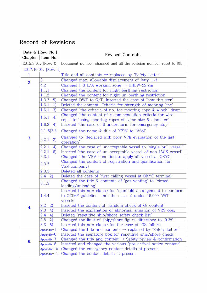
Record of RevisionsDate & [Rev. No.] Revised ContentsChapter Item No.2015.8.01. [Rev. 0] Document number changed and all the revision number reset to [0]. 2017.10.01. [Rev. 1]
1. Title and all contents → replaced by ‘Safety Letter’
2. 3. Changed max. allowable displacement of Jetty-1~34.2 Changed J–3 L/A working zone → HHLW+22.2m
3.
1.1.1 Changed the content for night berthing restriction1.1.2 Changed the content for night un-berthing restriction1.3.2 5) Changed DWT to G/T, Inserted the case of ‘bow thruster’1.6.1 1) Deleted the content ‘Criteria for strength of mooring line’1.6.1 3) Changed ‘the criteria of no. for mooring rope & winch’ drum
1.6.1 4) Changed ‘the content of recommendation criteria for wire rope’ to ‘using mooring ropes of same size & diameter’
1.6.3 4) Inserted ‘the case of thunderstorm for emergency stop’2.1 5)2.3 Changed the name & title of ‘CSS’ to ‘VSM’
2.2.1 2) Changed to ‘declared with poor VPR evaluation of the last operation’
2.2.1 4) Changed the case of unacceptable vessel to ‘single hull vessel’2.2.1 6) Inserted ‘the case of un-acceptable vessel of non-IACS vessel’2.3.1 Changed ‘the VSM condition to apply all vessel at OKYC’
2.3.2 Changed the content of registration and qualification for VSM(company)
2.3.3 Deleted all contents2.4 2) Deleted the case of ‘first calling vessel at OKYC terminal’
3.1.3 Changed the title & contents of ‘gas venting’ to ‘closed loading/unloading’
4.
1.4.4Inserted this new clause for ‘manifold arrangement to conform to OCIMF guideline’ and ‘the case of under 16,000 DWT vessels’
2.2 2) Inserted the content of ‘random check of O2 content’2.3 4) Inserted the explanation of abnormal situation of VRS ops.2.4 4) Deleted ‘repetitive ship/shore safety check-list’2.8 2) Changed the limit of ship/shore figure difference to ‘0.3%’3.3 5) Inserted this new clause for the case of IGS failure
6.
Appendix-1 Changed the title and contents → replaced by ‘Safety Letter’Appendix-6 Inserted the signature box for repetitive ship/shore checkAppendix-7 Changed the title and content → Safety review & confirmationAppendix-8 Inserted and changed the various ‘pre-arrival notice content’Appendix-10 Changed the emergency contact details at presentAppendix-11 Changed the contact details at present
OKYC Terminal Information
& Regulations (Content)
Doc. No.
Rev. No.
: A-TQI-3007-01
: 1
- Contents -
Chapter 1. Safety Letter (Condition for Use of Terminal Facilities)
Chapter 2. Berth Information
1. Location
2. Jetty Direction and Tidal Information
3. Jetty Specification and the Target Vessel
4. Jetty Layout and Loading Arm Arrangement
Chapter 3. Terminal Safety Regulations
1. Berthing/Un-berthing Safety Regulation
2. Cargo Safety Regulation
3. General Safety Regulation
Chapter 4. Cargo Operation Procedure
1. Procedure and Preparations before Cargo Operation for Vessel
2. Loading Operation
3. Discharging Operation
Chapter 5. Emergency Plan
1. Emergency Procedure
2. Emergency System of Terminal
3. Emergency Plan of Vessel
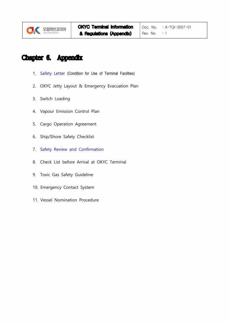
Chapter 6. Appendix
1. Safety Letter to Master (Condition for Use of Terminal Facilities)2. OKYC Jetty Layout & Emergency Evacuation Plan3. Switch Loading4. Vapour Emission Control Plan5. Cargo Operation Agreement6. Ship/Shore Safety Checklist7. Ship/Shore Repetitive Safety Check List8. Check List prior to Arrival at OKYC Terminal9. Toxic Gas Safety Guideline
10. Emergency Contact System11. Vessel Nomination Procedure
OKYC Terminal Information
& Regulations (Chapter 1.)
Doc. No.
Rev. No.
:
: 0
Chapter 1. Condition for Use of Terminal Facilities
Safety Letter (Appendix-1.)
Dear the Master,
Responsibility for the safe conduct of operations while your ship is at this terminal
rests jointly with you, as Master of the ship, and with the responsible Terminal
Representative. We wish, therefore, before operation start, to seek your full
co-operation and understanding on the safety requirements set out in the
Ship/Shore Safety Check-List, which are based on safe practices that are widely
accepted by the oil and tanker industries.
We expect you, and all under your command, to adhere strictly to these
requirements throughout your ship’s stay alongside this terminal and we, for our
part, will endure that our personnel do likewise, and co-operate fully with you in
the mutual interest of safe and efficient operations.
Before the start of operations, and from time to time thereafter, for our mutual
safety, a member of the terminal staff, where appropriate together with a
Responsible Officer, will make a routine inspection of your ship to ensure that
elements addressed within the scope of the Ship/Shore Safety Check-List are being
managed in an acceptable manner. Where corrective action is needed, we will not
agree to operations commencing or, should they have been started, we will require
them to be stopped.
Similarly, if you consider that safety is being endangered by any action on the part
of our staff or by any equipment under our control, you should demand
immediate cessation of operations.
There can be no compromise with safety.
OKYC Terminal Information
& Regulations (Chapter 2)
Doc. No.
Rev. No.
: A-TQI-3007-01
: 1
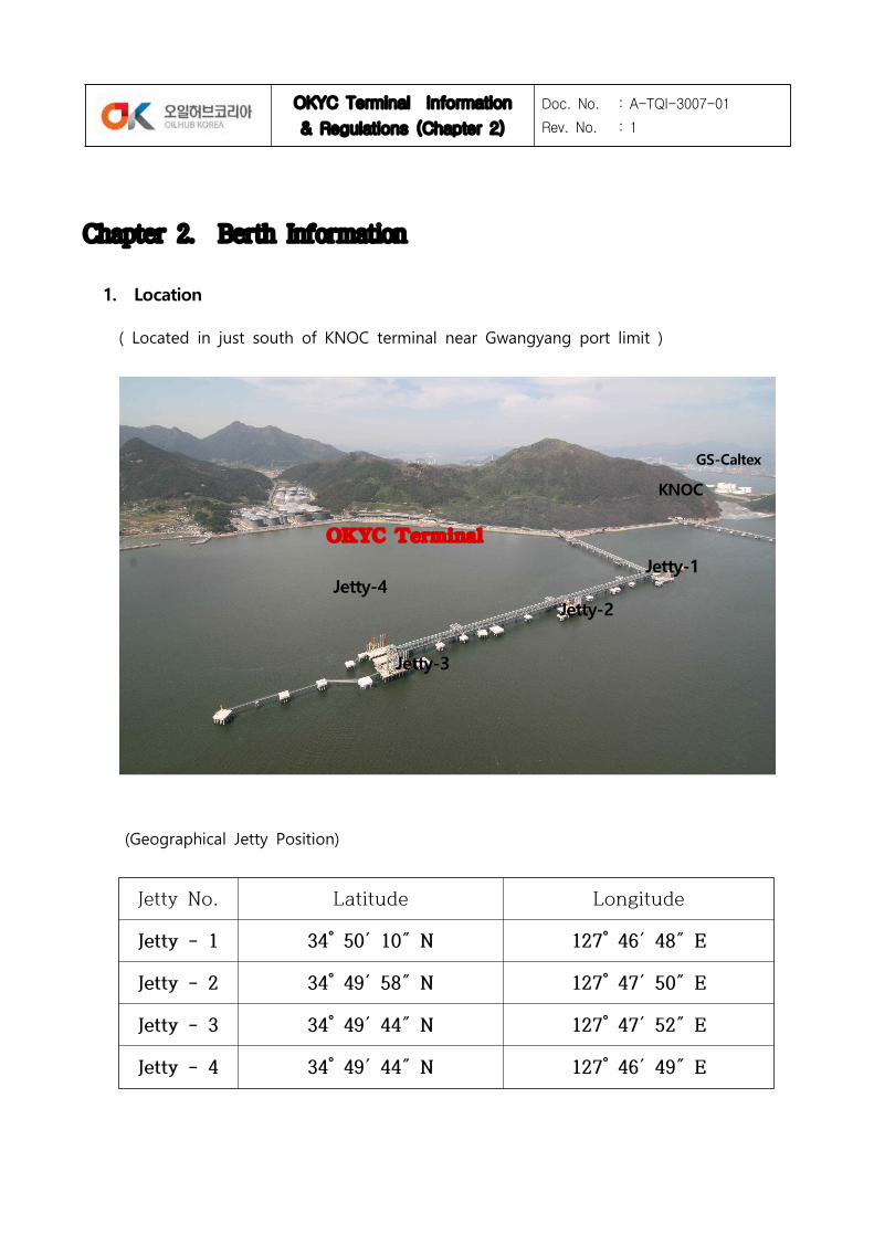
Chapter 2. Berth Information
1. Location
( Located in just south of KNOC terminal near Gwangyang port limit )
(Geographical Jetty Position)
Jetty No. Latitude Longitude
Jetty - 1 34° 50′ 10″ N 127° 46′ 48″ E
Jetty - 2 34° 49′ 58″ N 127° 47′ 50″ E
Jetty - 3 34° 49′ 44″ N 127° 47′ 52″ E
Jetty - 4 34° 49′ 44″ N 127° 46′ 49″ E
Jetty-1
Jetty-2
Jetty-3
Jetty-4
KNOC
OKYC Terminal
GS-Caltex

OKYC Terminal Information
& Regulations (Chapter 2)
Doc. No.
Rev. No.
: A-TQI-3007-01
: 1
2. Jetty Direction and Environmental Information
2.1 Direction : Lying on NNNE~ SSSW (174°~354°) direction
2.2 Environmental Information
Water Height (m) Tide Designed CriteriaDL(+) 4.240 (Obs. H.H.W)DL(+) 3.780 (H. W. L)DL(+) 3.616 (App. H.H.W)DL(+) 3.294 (H.W.O.S.T)DL(+) 2.820 (H.W.O.M.T)DL(+) 2.346 (H.W.O.N.T)DL(+) 1.808 (M.S.L)DL(+) 1.270 (L.W.O.N.T)DL(+) 0.796 (L.W.O.M.T)DL(+) 0.322 (L.W.O.S.T)DL(±) 0.000 (App. L.L.W)
3. Jetty Specification and the Target Vessel
Jetty length Depth Max. DraftMax. Disp.
(m/ton)Cargo
LOA (m)
Min.~ Max.
J-1 340 m 17.0 m 14.7 m 104,000 F.O. /
Clean Product150 ~ 295
J-2 380 m 18.0 m 15.5 m 154,000C.O.&F.O. /
Clean Product25 ~ 321
J-3 440 m 19.5 m *1) 17.7 m *2) 393,000C.O.&F.O. /
Clean Product220 ~ 382
J-4 200 m 12.0 m 10.4 m 40,000F.O. /
Clean Product25 ~ 169
*1) For vessel of draft over 16.0m can berth/unberth with consideration of depth allowance by tidal flood and appropriate UKC.
*2) J-3 is approved for 200,000 dwt by the port regulation, so VLCC can load within 200,000 ton of cargo under appropriate safety consideration
* Max. Tidal Current : 2.5 knot
* Allowable Wave Height : J-1 & J-2 : 4.17 m J-3 & J-4 : 6.58 m * Allowable Wind Speed : Jetty with Ship : 30 m/sec. Jetty only : 60 m/sec.

OKYC Terminal Information
& Regulations (Chapter 2)
Doc. No.
Rev. No.
: A-TQI-3007-01
: 1
4. Jetty Layout and Loading Arm arrangement
4.1 Jetty Layout : Refer to the attached Appendix-2.
4.2 Loading Arm Arrangement
Jetty MLA No. FluidDia Cppacity Working Area Size
(inch) (m3/h) Vertical Horizon Hight Out-Arm
J-1
LA-J101 F.O 12 2,000 HHWL +15,685
~LLWL +2,505
±2,365 18,700 10,000LA-J102 F.O 12 2.000LA-J103 VOC 10 3,750Nm3/hLA-J111 Product 10 1,500LA-J112 Prod/Comp 10 1,500
J-2
LA-J211 Product 10 1,500 HHWL +17,395
~LLWL +2,505
±2,115 22,500 11,500LA-J212 Prod/Comp 10 1,500LA-J203 VOC 16 3,750Nm3/hLA-J202 Crude/F.O 16 4,000LA-J201 Crude/F.O 16 4,000
J-3
LA-J305 Product 16 4,000HHWL
+22,200~
LLWL +6,105
±2,115 21,500 9,000
LA-J304 Product 16 4,000LA-J306 VOC 16 3,750Nm3/hLA-J303 Crude/F.O 16 4,000LA-J302 Crude/F.O 16 4,000LA-J301 Crude/F.O 16 4,000
J-4
LA-J401 F.O 10 1,200 HHWL +10,195
~LLWL +1,503
±1,503 17,200 11,000LA-J405 VOC 6 3,750Nm3/hLA-J402 Gasoil 8 1,200LA-J403 Mogas/Comp 8 1,200LA-J404 Mogas/Comp 8 1,200
* L/A arrangement order : North ---->South
* Horizontal Warning Zone : left/right each 1 meter wider than Working Zone
* Atlantic 774 L/A : ERC attached
OKYC Terminal Information
& Regulations (Chapter 3)
Doc. No.
Rev. No.
: A-TQI-3007-01
: 1
Chapter 3. Terminal Safety Regulation
1. Berthing/Un-berthing Safety Regulation
1.1 Criteria for Berthing and Un-berthing
All Vessels berthing or un-berthing must meet the following operational criteria.
1.1.1 Vessels criteria restricted by daylight berthing only
1) All vessels more than 50,000 G/T
2) Vessels more than 30,000 G/T with dangerous cargo
3) Vessels with draft 8.5 m or more at Jetty-4
4) For vessels of 10,000~30,000 G/T : restricted during 23:00~05:00 only
1.1.2 Vessels criteria restricted by daylight un-berthing only
1) Vessels over than 13 m of draft
2) Vessels with draft 8.5 m or more at Jetty-4
1.1.3 Allowable maximum tidal current speed : 0.5 knot or less
* In case of un-berthing with draft of under 15m, un-berthing is permissible within
1.0 knot of the tidal current by berth master’s decision in considering of other
circumstances alright.
1.1.4 Allowable height of wave and swell (in case of 10 sec. or less of cycle period)
1) Vessels more than 30,000 DWT : 1.0 meter or less
2) Vessels 10,000 ~ 30,000 DWT : 0.7 meter or less
3) Vessels 10,000 DWT or less : 0.5 meter or less
1.1.5 When berth master considers the berthing operation is dangerous in his
judgement on weather and tidal condition at that time, the berthing operation
shall not be allowed.
1.2 Criteria on Wind Velocity
1) 14 m/sec. (27 knot) or more : Restrict berthing
2) 16 m/sec. (31 knot) or more : Stop cargo operation
3) 18 m/sec. (35 knot) or more : Disconnect loading arms

OKYC Terminal Information
& Regulations (Chapter 3)
Doc. No.
Rev. No.
: A-TQI-3007-01
: 1
4) 20 m/sec. (39 knot) or more : Un-berth
5) 26 m/sec. (50 knot) or more : Close terminal
* In case of typhoon approach, the maximum instantaneous wind speed should be
the basis, and the Authority instruction should be followed.
* When electrical storm stays nearby or approach in the vicinity of terminal and/or
considering any possibility of danger on berthing operation, the berthing
operation shall not be allowed.
1.3 Criteria for Pilotage and Use of Tugboats when berthing/un-berthing
1.3.1 According to the Pilotage Laws of Korea, Oil tankers more than 500 G/T
should arrange pilot for berthing/un-berthing operation.
1.3.2 Use of Tugboats :
The master shall comply with the following criteria for use of tugboat additional
to the Reg. of Tug Operation for Yeosu and Gwangyang Port requirements;
1) All Vessels of 500 G/T or more should use tugboat
2) For vessels of berthing/un-berthing at J-4 with her draft 8.5m or more, one(1)
more tugboat of 2,500H.P. than the above regulation should be used.
3) Vessels laden dangerous cargo over 10,000 G/T should use one more tugboat
with 2,000H.P.
4) Numbers of tugboats required shall be increased depending upon weather, sea
conditions, or terminal request as safety reason.
5) At least two(2) tugboats should be used for vessels of 1,500G/T or more.
* when master of vessels which available bow-thruster inform to terminal, only
one tugboat can be used for un-berthing.
6) Whenever following conditions exist or are expected, the master should arrange
additional tugboats to maintain ship’s condition;
* Significant increase in wind speed or change in wind direction, particularly if
the vessel have high freeboard
* Expecting her bottom touch by significant swell, or period of maximum tidal
flow, or her limited UKC, or close passing of big ship.
1.4 Regulation for Vessel Approaching to Jetty Fender
1.4.1 Lateral approaching angle
OKYC Terminal Information
& Regulations (Chapter 3)
Doc. No.
Rev. No.
: A-TQI-3007-01
: 1
This is an angle formed by jetty fenders line and ship’s lateral side. Vessel
should be berthed parallel to jetty fenders face as far as possible.
1) Angle of approach : 6° or less (within 30 m range from jetty)
2) Approach impact angle : 3° or less (when touch jetty fender)
1.4.2 Approaching speed (within 30 m range from fender)
Vessel’s lateral approaching speed to jetty fender is defined as follows;
1) 5 cm/sec or less ; allowable speed
2) 6~10 cm/sec : warning speed
3) over 11~15 cm/sec : critical (the master & pilot will be black-listed and
held accountable if in case of fender damage)
1.5 General Regulation for Berthing/Un-berthing
1.5.1 In Dense Fog
The instruction of VTS(Vessel Traffic Service) should be followed.
1.5.2 Additional Regulation for Berthing/Un-berthing
1) In case where a vessel comes alongside without any help of tugboats, both
anchors should be ready to use (to prevent damaging jetty structure with
excessive approaching speed; or for emergency anchoring due to main engine
failure).
2) When vessel has berthing problems with her main engine failure or bad
weather conditions, the master should anchored promptly near the anchoring
basin with reporting the situation to VTS.
3) All the cargo tank hatch should be closed during berthing and un-berthing
operations.
4) Flame arrester of the engine room funnel should be kept closed during the
berthing/un-berthing and cargo operation.
5) Berthing/un-berthing operations basically should be carried out around slack
water time.
6) For un-berthing, all the vessels should check removal of oil-boom around her
before her main engine test (Ahead/Astern).
1.6 Moorings management Regulation
OKYC Terminal Information
& Regulations (Chapter 3)
Doc. No.
Rev. No.
: A-TQI-3007-01
: 1
1.6.1 Numbers and the Thickness of Mooring Ropes
1) Vessels berthing at OKYC terminal should have appropriate numbers and size of
mooring ropes as OCIMF ‘Mooring Equipment Guideline 3rd Edition’.
2) Minimum requirements for small vessels:
* Head Line / Stern Line: 2 lines each
* Breast Line / Spring Line: 1 line each on fwd and aft
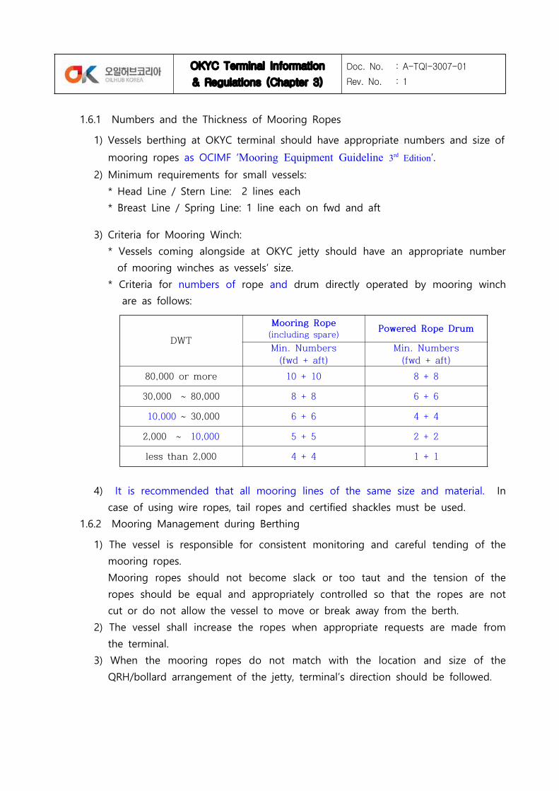
3) Criteria for Mooring Winch:
* Vessels coming alongside at OKYC jetty should have an appropriate number
of mooring winches as vessels’ size.
* Criteria for numbers of rope and drum directly operated by mooring winch
are as follows:
4) It is recommended that all mooring lines of the same size and material. In
case of using wire ropes, tail ropes and certified shackles must be used.
1.6.2 Mooring Management during Berthing
1) The vessel is responsible for consistent monitoring and careful tending of the
mooring ropes.
Mooring ropes should not become slack or too taut and the tension of the
ropes should be equal and appropriately controlled so that the ropes are not
cut or do not allow the vessel to move or break away from the berth.
2) The vessel shall increase the ropes when appropriate requests are made from
the terminal.
3) When the mooring ropes do not match with the location and size of the
QRH/bollard arrangement of the jetty, terminal’s direction should be followed.
DWT
Mooring Rope(including spare) Powered Rope Drum
Min. Numbers (fwd + aft)
Min. Numbers (fwd + aft)
80,000 or more 10 + 10 8 + 8
30,000 ~ 80,000 8 + 8 6 + 6
10,000 ~ 30,000 6 + 6 4 + 4
2,000 ~ 10,000 5 + 5 2 + 2
less than 2,000 4 + 4 1 + 1
OKYC Terminal Information
& Regulations (Chapter 3)
Doc. No.
Rev. No.
: A-TQI-3007-01
: 1
4) The vessel should be ready to un-berth with her main engine start whenever
necessary, even during the cargo operation.
5) Should the vessel move unduly in the berth, the terminal may call for the
assistance of tugs to secure the vessel.
1.6.3 Cargo operation should be stopped immediately and un-berthing should be
prepared in cases as follows:
1) When safety risks of fire and/or explosion have been found.
2) When oil leakage is found around the vessel or when vessel/equipment defects
or damages which could cause oil leakage are found.
3) When the separation distance between the vessel and jetty fender is over 0.5
meter of allowable separation distance.
4) When wind velocity (max. average) is over 16 m/sec. or found thunderstorm
nearby in the vicinity of terminal.
5) When there are possibility of storms and waves that could break loading arms
and hoses.
1.6.4 In the following emergency cases, necessary measures should be taken and
vessels should be un-berthed promptly:
1) When safety accidents such as fire and explosion are highly expected or already
have happened.
2) When the separation distance between the vessel and jetty fender is over
1meter of maximum allowable separation distance.
3) When wind velocity is over 20 m/sec. or wave height is over 1 meter.
2. Cargo Safety Regulation
2.1 Definition
1) Age of Vessel
Age of vessel means present date (mm/yy) minus vessel delivery date (mm/yy)
(month should be converted to a decimal)
2) VPR (Vessel Performance Report)
The report made by the Loading Master and evaluated as one of five ratings like
OKYC Terminal Information
& Regulations (Chapter 3)
Doc. No.
Rev. No.
: A-TQI-3007-01
: 1
Excellent(5), Good(4) Fair(3) Poor(2) Bad(1) after checking the vessel operation
management condition, the maintenance of cargo-handling equipments, and cargo
operation ability of crew and officers including chief officer.
3) Oil Major Inspection
Oil Major Inspection is a kind of SIRE(Ship Inspection Report Programme)
inspection as standard of oil majors (BP, Shell, ExxonMobil, ChevronTexaco, Total,
etc.)
4) TSI (Terminal Safety Inspection)
TSI means a safety inspection performed by the berth master or the loading
master or an inspector(approved and notified by OKYC terminal) before berthing
to prove and ensure ship’s safe cargo operation capability according to the
terminal regulations
5) VSM (Vessel Safety Manager)
VSM is hired by the ship-owner in order to supervise and support the vessel’s
safe cargo operation in cooperation with terminal according to the terminal
regulations.
VSM should attend on board all the time of cargo operation (from L/A on to L/A
off) to enhance efficiency of cargo operation and handle complicated problems
may arise during staying at terminal.
OKYC terminal sets standards of qualification for VSM to ensure VSM’s eligibility
according to regular familiarization and training course for them.
2.2 Criteria of Berthing depending on Vessel Condition
2.2.1 Vessels of following cases are prohibited berthing at OKYC terminal.
1) All oil tankers whose age is more than 23 years
2) Vessel declared with poor VPR evaluation of the last operation
3) Vessel listed on OKYC Terminal’s or Yeosu Port’s black-list
4) Vessel with single-hull structure
5) Vessel having a critical history like fire, explosion and oil pollution within recent
3 years
6) Vessel have no classification certificate from one of IACS (International Association of
OKYC Terminal Information
& Regulations (Chapter 3)
Doc. No.
Rev. No.
: A-TQI-3007-01
: 1
Classification Societies)
2.2.2 Vessels carring on board toxic cargo which continuously emits toxic fumes of
more than 50 ppm of H2S content and/or more than 10 ppm of Benzene
content are not acceptable for berthing at OKYC terminal unless the cargo
specifications and the cargo operation procedures have been approved by
OKYC terminal when vessel acceptability clearance.
2.3 VSM (Vessel Safety Manager)
2.3.1 All oil tankers loading/un-loading at OKYC terminal should employ VSM to
work on board to secure safe cargo operation during the whole cargo
operation hours under owner’s or charterer’s expense.
2.3.2 Qualifications for VSM
1) The VSM or VSM company for working on board at OKYC terminal should
contract with OKYC for registration and accomplish the OKYC on-job training
program every years.
2) The qualification of VSM should be in accordance with OKYC terminal guideline
and the Maritime Law of Korea.
2.4 TSI (Terminal Safety Inspection)
Terminal requires safety inspection before berthing for the following vessels under
owner's time/expense.
The safety inspector(company) should be approved by OKYC.
1) All vessels of age 16 year or more
2) Following vessels below 16 year age
* Maiden voyage
* In case of first voyage just after change of owner/technical operator
* Lay-up more than 3 month during recent one year.
* Vessel on OKYC black-list and Vessels operated by the owners/operators on
OKYC black-list
* Poor performance vessel reported through the past operation at OKYC
terminal.
* First calling vessel at OKYC terminal or Re-calling vessel over 3 years from last

OKYC Terminal Information
& Regulations (Chapter 3)
Doc. No.
Rev. No.
: A-TQI-3007-01
: 1
calling
3. General Safety Regulation
3.1 Fire/Explosion Prevention
3.1.1 Naked light (Open Flame)
On vessels at the berth, any operations using machines that could set off sparks
or any use of flammable machines such as steel process operations including
grinding, servicing and repairs including welding, incineration and chipping &
scraping are prohibited.
In addition, handling materials such as the combustion of magnesium –composed
alloy, which could set off sparks even if people cannot catch it with the naked
eye.
The use of galley stoves and other cooking appliances must be non-flammable
such as electric hot plates.
3.1.2 Smoking
No smoking is allowed on board and at jetty while the ship is at the berth
except in places which have been jointly approved by the Master and the Loading
Master and named as ‘Smoking Room’.
When such violations are found, sanctions including suspension of cargo operation
and/or un-berthing can be imposed until Master’s statement is submitted or other
related effective measures are taken.
3.1.3 Closed loading/unloading and IGS (Inert Gas System)
1) On vessels without inert gas system, the precautions highlighted in ISGOTT
section 11.8.2 (Measuring and Sampling Non-Inerted Tanks) should be complied.
2) Vessels operating with inert gas should be equipped with proper venting
system and the following two independent systems should be fully operational.
i) Closed gauging system that allows the tank contents to be monitored
without opening tank apertures.
ii) Overfill alarm arrangement that providing audible and visual indication.
3) Gas freeing or tank cleaning shall not be permitted at berth.
3.1.4 Handling of Electric Equipment including Hand Torch, Transceiver

OKYC Terminal Information
& Regulations (Chapter 3)
Doc. No.
Rev. No.
: A-TQI-3007-01
: 1
The use of electric appliances near or in the area where there is a danger of gas
leakage or gas residue such as on deck, ballast tanks, pump room and cargo
tanks is strictly prohibited.
Only hand torches or transceivers of intrinsically safe approved types for use in
flammable atmosphere can be used.
3.1.5 Radio Transmitting Aerials and Radar
The vessel’s main radio transmitting aerials and radar must be switched off when
the vessel is in the process of cargo operation at the berth.
3.1.6 Boiler (Sparks from Funnel)
Boiler tubes must not be blown while the vessel is at the berth.
Every precaution must be taken so that sparks and soot are not emitted from the
stack.
3.1.7 Use of Mobile phone
While oil tanker alongside with VOC cargo on board, the use of mobile phone at
the jetty is strictly prohibited.
3.1.8 Toxic gas Precautions including H2S & Benzene gas
To prevent exposure phase of high toxic gas (including H2S & Benzene)
concentrations more than 5 ppm by volume, special precautions should be
arranged through the cargo operation.
Personnel should always carry personal gas monitor when working in enclosed
spaces, gauging, sampling, entering a pump room, connecting and disconnecting
loading arms, cleaning filters, draining to open containments and mopping up
spills if toxic gas concentrations could exceed the TLV-TWA.
Refer to the attached Appendix-9. for the details of safety guideline
3.2 Oil Pollution Prevention
3.2.1 Prohibit Dumping Oil and Garbage into the Sea
It is strictly prohibited to discharge all kind of waste including oily waste into the
sea.
3.2.2 Sea and Overboard Discharge Valves
Before entering port, overboard valve/line connected to cargo lines should be
OKYC Terminal Information
& Regulations (Chapter 3)
Doc. No.
Rev. No.
: A-TQI-3007-01
: 1
shut and lashed and must be closed with blind plates inside.
Spool pieces of ballast lines connected to cargo lines should be separated and
then shut down with blind plates.
3.2.3 Scuppers
Before cargo operation commences, all deck scuppers must be plugged and be
checked for leakage with pouring water when necessary.
When there is necessity of draining through scuppers due to rain and so on,
firstly make sure there is no oil on the surface with reporting it to terminal and
drain it. Duty crew must watch closely the whole process.
3.2.4 Blind Plate for Manifolds
All unused cargo line manifolds and ballast line manifolds must be fully closed
and fitted with blank flanges with full bolt tightening.
3.2.5 Oil Pollution Prevention from Engine Room
The bilge separator in engine room must be shut and lashed, and should post a
warning notice by chief engineer.
3.2.6 Ballasting/De-ballasting
Before ballasting or de-ballasting, the vessel should notify the terminal for
checking if it is necessary to adjust the time of ballasting/de-ballasting due to
expecting bad weather or any change of cargo operation procedure
Before de-ballasting, the vessel should check any oil film in the ballast tank.
If any oil film is found on the surface at the beginning or during the
de-ballasting, the operation must be immediately stopped and notify the terminal.
The de-ballasting operation can only be resumed after it is investigated that there
is no problem after the cause identification.
3.2.7 Shipboard Oil Pollution Emergency Plan (SOPEP)
In accordance with item 26 of International Convention for the Prevention of
Marine Pollution from Ships (Marpol) 73/78 Annex I, Oil tankers of G/T 150 or
more should have SOPEP on board approved by classification society or the
authorized agency, and utilize it when needed.
3.3 Other Safety Regulations

OKYC Terminal Information
& Regulations (Chapter 3)
Doc. No.
Rev. No.
: A-TQI-3007-01
: 1
3.3.1 Main Engine Stand-by
Vessels at the berth should prepare her main engine all the times for emergency
un-berthing with short notice.
3.3.2 Repairs and Inspection
1) When a vessel needs repairs, maintenance services or inspection at the berth, it
should be permitted by Berth Master prior to ship arrival through agent.
2) The following operations are not allowed basically at the berth.
* Work or inspection carried out inside of the tank of vessel
* Work carried out outside of the gunwale (=gutter bar) of vessel
* All kind of work that could hinder vessel’s sailing ability including main
engine maintenance
* All kind of work that can be a source of ignition to explosive gas
* Gas removal operations from tank and tank cleaning operations
* De-ballasting of oily ballast water
3) All inspections should be carried out during the time before cargo operation or
after maintaining normal steady cargo operation.
3.3.3 Lashing Ropes
Lashing ropes are to be ready and fitted with every manually operated valves on
cargo line.
3.3.4 Supply
1) While cargo operation, any type of supply or discharge materials is prohibited.
2) When loading and unloading of essential materials for the vessel is needed,
vessel should request the berth master’s permission through agent in advance.
This operation can be carried out before or after the cargo operation
3.3.5 Main Engine Test before Un-berthing
Vessels should carry out the main engine test before un-berthing, but only after
checking if loading arms, gangway and oil boom are in a safe condition.
3.3.6 Safety Regulations according to the International laws and conventions.
Almost safety regulations and customs commonly applied to other marine
terminals, such as ISGOTT(International Safety Guide for Oil Tanker/Terminal) of
OKYC Terminal Information
& Regulations (Chapter 4)
Doc. No.
Rev. No.
: A-TQI-3007-01
: 1
OCIMF(Oil Companies International Marine Forum), Mooring Equipment Guideline
and etc. are also applied to OKYC terminal safety regulation.
Chapter 4. Cargo Operation
1. Procedure and Preparations before Cargo Operation for Vessels
1.1 Berthing Acceptability Clearance;
Vessels want to visit OKYC terminal have to request her berthing acceptability from
terminal with the following informations at least 2 weeks before her calling OKYC.
(Refer to the Appendix-11. Vessel Nomination Procedure)
1) Q88
2) Cargo details to load/unload
3) DDR(Due Date Range) of cargo operation at OKYC
4) Mooring equipments diagram on deck (ex, General Arrangement)
1.2 Additional informations and submittance of documents from the Contracted Vessel;
Vessels proceeding to OKYC terminal for cargo operation shall inform and/or submit
the following items;
1) ‘The master’s declaration’ (Appendix-1.)
2) ‘Check list before arrival OKYC terminal’ (Appendix-8.)
3) Cargo documents, crew List, port of call, and other documents if requested
4) International Tonnage Certificate, Ship Security Information
5) Stowage plan or discharging plan
6) Arrival draft and estimated sailing draft
OKYC Terminal Information
& Regulations (Chapter 4)
Doc. No.
Rev. No.
: A-TQI-3007-01
: 1
7) Agent name in Korea, and other informations if requested
1.3 Notice of ETA;
Vessels shall confirm her ETA at OKYC terminal as the following time and
occasions:
1) 14/7/4 days before its ETA at the terminal as the case may be.
2) 48/24/12 hours before such ETA
3) In the event of any variation of more than one(1) hour after 48 hours ETA,
vessels shall advise immediately the terminal of its ETA.
1.4 All vessels proceeding to OKYC terminal have to take following actions prior to
arrival at OKYC terminal
1.4.1 For loading VOC cargo oil
1) Vessel have to take appropriate action to observe ‘OKYC Vapour Emission
Control Plan’ (Appendix-4) and inform the result to OKYC through ‘Check List
Before Arrival at OKYC Terminal’ (Appendix-8) to prevent clog from terminal
VRS(Vapour Return System) by ship’s rusty dust and condensate water.
2) In case of inadequate condition by inspection, terminal can reject loading
operation and vessel is responsible for all consequences arising from this
result.
1.4.2 Before approaching pilot station, vessel should carry out sufficient preparations
to prevent emission of black soot from funnel exhaust and/or scrubber/deck-seal
water discharge outlet.
1.4.3 During approaching, vessel should have all cargo handling system on standby
for immediate loading/unloading operation upon completion of cargo safety
meeting.
1.4.4 Manifold Arrangement should conform to OCIMF ‘Recommendations for Oil
Tanker Manifolds and Associate Equipment’ and vessel should prepare proper
reducers to fit with shore loading arm arrangement (described in Chapter 2, 4.2)
and the Mooring Plan (to be presented before berthing).
1) Manifold flanges to connect shore loading arms should have proper thickness

OKYC Terminal Information
& Regulations (Chapter 4)
Doc. No.
Rev. No.
: A-TQI-3007-01
: 1
conforming to ANSI 150 Lbs flange.
2) For small tankers under 16,000 dwt : the manifolds should have sufficient space
that required on ‘Check List Before Arrival at OKYC Terminal’ (Appendix-8)
2. Loading Operation
2.1 Switch Loading and Static Electricity
“Switch loading” means that a previous loaded cargo was much high vapourable
liquid and a present cargo to load into same tank is relatively low vapourable liquid.
In this case (switch loading), there are much possible generated ‘static electricity/
electrostatic field’ throughout the tank both in the liquid surface and in the ullage
space at initial/during loading.
Static electricity presents fire and explosion hazards during handling of petroleum,
and tanker operations are no exception. Certain operation can give rise to
accumulations of electric charge which may be released suddenly in electrostatic
discharge with sufficient energy to ignite flammable hydrocarbon gas/air mixtures.
To avoid any possible ignition of static electricity, vessels in case of switch loading
are strongly requested to fully inerted condition if fitted with IGS and/or gas free
means previous flammable gas content shall be less than 15%LEL before
commencement of present cargo loading, and others than above, requested linear
velocity in the branch line to each individual cargo tank shall not exceed 1m/sec.
until loading bell mouth levels are sufficiently filled and immersed with oil.
And also to release smoothly human static electricity, crew must be earthed
properly with physical hand-touch using metals/discharge plates located onboard
before turn to their cargo work on deck. Refer to the Appendix-3.
.
2.2 Tank Inspection
1) Only as the approval by cargo surveyor and/or loading master after tank
inspection, cargo loading operation can be started to carry out.
2) Random checks of oxygen contents should be carried out for IGS tanker, and
the switch Loading clause (defined 2.1) should be observed for non-inerted
tanker.
OKYC Terminal Information
& Regulations (Chapter 4)
Doc. No.
Rev. No.
: A-TQI-3007-01
: 1
3) All the gauging and sampling operation should be carried out by closed system
like using vapour-lock gauging point to prevent exposure of toxic gas.
To prevent high H2S or Benzene concentrations, personal gas detector and
special precautions should be arranged.
2.3 Vapour Return Line
1) When loading VOC cargo, ship/shore VRS(vapour return system) should be
operated to prevent VOC emission to air.
2) Terminal loading master should inspect the inside condition of ship’s vapour
return line by visual and/or blowing method before L/Arm connection.
3) In case of inadequate condition by loading master’s inspection, terminal can
reject loading operation and vessel is responsible for all consequences arising
from this result.
4) During normal loading operation, vessel should check the condition of VRS
regularly and report to terminal immediately when tank pressure reaches
beyond of parameter which ship/shore discussed and agreed.
2.4 Cargo Safety Meeting
1) Before having cargo safety meeting, terminal loading master can inspect her
mooring condition, cargo equipments on deck & CCR, safety managing
condition, and etc.
2) Unless loading master’s comment otherwise, cargo safety meeting basically
should be held together with the master, chief officer, and chief engineer.
3) Vessel and terminal have to confirm the following items and declare ‘Cargo
Operation Agreement’ (Appendix-5.) with both signature.
* Explanation and correct action for non-conformity items during safety
inspection and/or safety round on deck
* Major items of Terminal Informations and Regulations
* Cargo name, cargo quantity, cargo specification, ship’s stowage plan
* MSDS hand over and explanation of the important content (ex.: H2S, Benzene)
* Method of ship/shore communication during cargo operation (cargo operation
to be stopped when communication failure)
* Initial/Max./Topping-off loading rate
* Emergency Shut-down Procedure to prevent possible danger of pressure surge
OKYC Terminal Information
& Regulations (Chapter 4)
Doc. No.
Rev. No.
: A-TQI-3007-01
: 1
which exceed the agreed pressure limit including explanation of loading arm
envelope and ERC(Emergency release Coupling) operating condition
* Tank condition for loading(previous cargo, oxy./gas contents etc.)
* Arrival draft, de-ballasting hours, expected sailing draft
* Special ship’s condition that terminal have to be acknowledged.
4) Following documents have to be declared with signature.
* ‘Ship/Shore Safety Check List’ (Appendix-6)
* Notice of Readiness
5) In case small tankers that have no CCR installed should prepare Cargo
Operation Display Board at ship’s manifold area, and this board display the
important contents of cargo operation agreement.
2.5 De-ballasting
1) Vessel officer have to confirm ship’s ballast tank condition not contaminated
with any oily contents and record it accordingly.
2) On start de-ballasting, vessel report this to terminal and arrange deck crew to
watch around overboard sea area.
3) Terminal can request vessel to suspend de-ballasting because such situation of
un-berthing would be expecting due to bad weather & etc.
2.6 Comparing Loading Rate & Loaded Q’ty
1) Loading rate and loaded quantity should be checked and recorded every hour
and reported to terminal when requested.
2) In case the hourly loaded quantity is too different from previous one, vessel
should report to terminal and confirm again its reason by re-check and/or
calculation.
2.7 Topping-Off and Completion of Loading
1) Before topping-off ship’s cargo tanks, vessel should request to reduce loading
rate for safe topping-off operation with sufficient pre-notice like 30 minutes as
agreed on Cargo Operation Agreement .
2) Even though shore-stop, vessel should request to stop loading when expecting
dangerous situation like over-flow.
OKYC Terminal Information
& Regulations (Chapter 4)
Doc. No.
Rev. No.
: A-TQI-3007-01
: 1
3) On completion of loading, vessel should close manifold valves after that confirm
the loading arm valves have been closed.
2.8 Cargo Gauging, Calculation and Documentation
1) Cargo gauging and calculation should be carried out by the appointed surveyor,
and loading master should attend unless any special reason.
2) In case that ship’s figure differs from terminal figure 0.50.3% or more,
ship/shore staff and surveyor should carry out re-gauging and report to
terminal.
3) Shipping Documents are basically as follows unless additional D/I(document
instruction) requested.
* B/L --- Issued by Vessel(Master/Agent)
* Certificate of Quantity --- Issued by Terminal(Surveyor)
* Certificate of Quality --- Issued by Terminal(Surveyor)
* Certificate of Origin --- Issued by Terminal(Surveyor)
* Cargo Manifest --- Issued by Vessel(Master/Agent)
* NOR --- Issued by Vessel(Master/Agent)
* Time Statement of Fact --- Issued by Vessel(Master/Agent)
* Protest (if any) --- Issued by Vessel(Master) and/or Terminal
3. Discharging Operation
3.1 Gauging and Sampling
1) Before discharging operation, the appointed cargo surveyor should carry out
exact gauging and calculation.
This gauging hours are not included in contract cargo operation time.
2) In case that ship’s figure differs from B/L figure 0.3% or more, the result should
be reported to terminal and wait for instruction to start discharging commence.
3) Vessel should hand over the loading port cargo documents and samples.
4) Vessel have to help sampling work as per terminal and/or surveyor’s request.
5) All the gauging and sampling operation should be carried out by closed system
like using vapour-lock gauging point to prevent exposure of toxic gas.
To prevent high H2S concentrations more than 5 ppm, personal gas detector
and special precautions should be arranged.
OKYC Terminal Information
& Regulations (Chapter 4)
Doc. No.
Rev. No.
: A-TQI-3007-01
: 1
3.2 Cargo Safety Meeting
1) Vessel should present following documents to terminal loading master and/or
surveyor.
* Discharging Plan
* Ship’s Particulars
* Bill Of Lading
* Quantity/Quality Certificate
* Cargo documents of loading port
* MSDS
* Etc.
2) The same items as cargo safety meeting of loading operation (defined 2.4) are
almost applicable.
3.3 Commencement of Discharge
1) In almost case that gas & vapour are filled in cargo pipe line on deck and pump
room, the gas and vapour should be extracted by close-circulation of cargo.
Loading master may advise the appropriate method.
2) When start centrifugal pump, vessel should prevent pressure surge caused by
excessive start RPM. The pump delivery valve should be closed position until the
pump stabilized with minimum RPM.
3) If there are severe vibration on loading arm and/or pipeline at the start of
discharging, vessel should stop or reduce the discharge flow until confirming the
reason and remedy it completely.
4) The start and control discharge operation by pump delivery valve should be
carried out very carefully with loading master’s direction to prevent damage on
terminal equipments by pressure surge or back-flow from shore.
5) In the cases of IGS failures, the discharging operation should be suspended
immediately to prevent air coming into the tanks.
3.4 Report Discharge Rate & Q’ty and Change of Pump Operation
1) Vessel should check and calculate the discharging quantity periodically(hourly) and
report to terminal when requested.
OKYC Terminal Information
& Regulations (Chapter 4)
Doc. No.
Rev. No.
: A-TQI-3007-01
: 1
2) Except emergency case and stripping stage, the considerable change of pump
operation should be notified to terminal in advance.
3) For stop cargo pump operation, notification should be given step-by-step like 30
minutes, 10minutes, 5 minutes, 1 minute to stop, or otherwise 2,000 ㎘, 1,000 ㎘,
500 ㎘, 100 ㎘, 50 ㎘, 10 ㎘ to stop.
3.5 Caring for Mooring Line & Gangway
1) In discharging tanker docked at the jetty, Mooring takes excessive tension easily
caused by tide and changing of draft. In this case sometimes Vessel has lose the
position due to damaged mooring, so duty sailors often adjust the entire mooring
to maintain proper tension.
2) Vessel have responsibility to maintain mooring management ‘Not Too Tight, Not
Too Loose’ within mooring rope permissible tension and never away from the berth.
3) Vessel crew have to watch shore gangway not to face dangerous situation by
ship’s height change and notify to terminal to adjust it if in need.
3.6 Crude Oil Washing (COW)
1) COW operation strictly restricted in performing only within 25% volume of tank
capacity of laden tank. This is to be declared when cargo safety meeting and
recorded on ‘Cargo Operation Agreement’ (Appendix-5.)
2) Vessel should check as the related safety check-list before COW operation, and for
the oxygen content of tank, notify terminal for grant. Never carry out COW
operation in case of over 8% of oxygen content.
3) COW operation should be carried out as ‘Closed Cycle’ and the washed oil should
be discharged at final stage of discharging unless otherwise decided by terminal.
3.7 Stripping
When stripping stage, the pump RPM and delivery valve opening should be
carefully controlled to prevent severe vibration and/or pressure surge from sucking
vapour.
3.8 Final Discharging and Tank Dry Inspection
1) Vessel should notify her ETC(Estimated Time of Completion) to terminal at least
OKYC Terminal Information
& Regulations (Chapter 5)
Doc. No.
Rev. No.
: A-TQI-3007-01
: 1
1 hour before completion.
2) At the end of discharging stage, all the cargo pipe line including loading arm(s)
should be fully drained and accomplished stripping except the small diameter
discharging line (Marpol line) and one loading arm to use at final discharging.
3) Only one loading arm should be used at the final discharging stage.
4) Before tank dry inspection, cargo surveyor and loading master should check the
following items.
* All the ship’s cargo pipe line were drained and stripped.
* Whole cargo discharging operation have been completed and pumps been
finished.
* All the important cargo valves were closed.
* Vessels is afloat with up-right condition without any list.
5) Tank dry inspection is basically carried out with dipping method using
vapour-lock inspection hole to prevent VOC emission.
Chapter 5. Emergency Plan
1. Emergency Procedure
1.1 Emergency Signal
In the event of fire or other emergency, series of long blast should be sounded
by whistle or siren.
1.2 Emergency Shutdown(Stop)
In case the following circumstances, ship and terminal should take emergency
shutdown(stop) cargo operation. Due regard should be given to the possible
dangers of pressure surge associated with any emergency shutdown procedure.

OKYC Terminal Information
& Regulations (Chapter 5)
Doc. No.
Rev. No.
: A-TQI-3007-01
: 1
1) When weather forecast typhoon approaching or wind velocity increase more than
16m/sec.(10 min. average) or wave (including swell) is higher than 1m.
2) When a fire breaks out or found oil spill around vessel(s).
3) When terminal representative has determined that it is too dangerous to continue
cargo operation due to breach of safety regulation or other matters.
4) When an accident is occurred on board.
1.3 Emergency Loading Arm Disconnection
ERC(Emergency release coupling) is equipped on crude/F.O. loading arms of Jetty-2
and all loading arms of Jetty-3.
ERC makes possible to disconnect loading arms from the vessel in a short period
on emergency case such as vessel over-drifting from berth, earthquake, fire, and etc.
1.4 Emergency Un-berthing Operation
In case the following circumstances, the master and terminal representative take
emergency action to un-berth after discuss the situation.
1) When weather forecast typhoon approaching or wind velocity increase up to
20m/sec. or wave (including swell) is higher than 1m.
(When the master and terminal representative conclude the situation dangerous
even though the wind speed is less than 20m/sec., emergency un-berthing should
be taken.)
2) When a fire breaks out vessel(s) around.
3) If loading work delay under the bad weather condition, the master should be
agree to un-berthing.
4) When terminal representative has determined that it is too dangerous to have
vessel alongside berth due to weather condition or other matters.
5) When an accident is occurred on board.
6) When VTS and/or related authority declares special direction.
.
1.5 Emergency Evacuation
When a emergency case of big fire or explosion of vessel/terminal have been
occurred or foreseen, all the people on jetty/vessel must escape from the danger
place through appropriate route as ‘OKYC Jetty Layout & Emergency Evacuation Plan’

OKYC Terminal Information
& Regulations (Chapter 5)
Doc. No.
Rev. No.
: A-TQI-3007-01
: 1
(Appendix-2) with consideration of following measures.
1) To request help like rescue boat from out-jetty using portable radio and
emergency contact list.
2) Use appropriate PPE like as life-jacket, life-ring, EEBD, breathing apparatus, etc.
3) In case of presence of toxic gas at the scene, refer to ‘Toxic Gas Safety
Guideline’ (Appendix-9.)
1.6 Emergency Measures and Notifications
When a fire of oil spill accident have been occurred on board, the master must
take appropriate initial emergency measure to control the emergency and inform the
situation to terminal representative without delay.
All the cargo, ballasting and bunkering operation must be stopped immediately
and oil in the loading arms should be drained out to prepare disconnection. Main
engine, steering gear, and all mooring equipments also should be ready to use.
1.7 Assistance of the Boats by the Terminal
In case that terminal representative has found an emergency situation and/or
judges that situation is imminent, he may request help directly from the assist boats
without prior agreement of the master.
In these cases, all mobilization cost of the boats must be charged on the vessel
or the owner.
1.8 Notification for Emergency and Summoning of Assistance
An emergency situation must be reported to the competent authority and the
concerned organizations using ‘Emergency Contact System’ (Appendix-10).
If either the master or terminal representative judges that the resources of the
vessel and terminal are not enough to overcome the emergency situation, assistance
from assisting organizations will be requested by terminal representative.
In this case, Emergency Contact System’ (Appendix-10) shall also be referred to.
1.9 Indemnification
The master of any vessel and its owner shall remain solely responsible for, and
OKYC Terminal Information
& Regulations (Chapter 5)
Doc. No.
Rev. No.
: A-TQI-3007-01
: 1
shall hold the terminal indemnified against, damage of terminal and expenses for
third party from whatever cause arising in consequence of all act and/or omissions of
the vessel’s personnel.
2. Emergency Plan of Vessel
2.1 Preparation
The master must have emergency procedures ready for immediate implementation
in the event of various type of emergencies such as a fire in cargo tanks/engine
room/living quarter, personnel injury, and oil spillage. All shipboard personnel must
be familiar with the procedures, be adequately trained and clearly understand the
action they would be required to take when responding to an emergency.
2.2 Fire-Fighting Equipment
Before commencement of cargo operation, fire-fighting equipment on the vessel
must be made ready for immediate use. A least two fire hoses (fwd and aft of
manifold) should be uncoiled and laid out and fire monitor should be aimed to the
manifold of jetty-side.
2.3 Emergency Towing Wire
Emergency Towing Wire should be made fast to bollard and prepared on deck or
maintained above water line on the opposite side hull of jetty.
2.4 Readiness to Move under Own Power
While the vessel is alongside at berth, her boiler, main engine, steering gear, and
other equipments essential for maneuvering must be maintained in a state of
readiness. With short notice, the vessel can move away from berth.
2.5 Materials for Oil Disposal
While the vessel is alongside at berth, materials for oil disposal must be ready for
immediate use. The use of chemicals requires permission of the authority.
OKYC Terminal Information
& Regulations (Appendix)
Doc. No.
Rev. No.
: A-TQI-3007-01
: 1
Chapter 6. Appendix
1. Safety Letter (Condition for Use of Terminal Facilities)
2. OKYC Jetty Layout & Emergency Evacuation Plan
3. Switch Loading
4. Vapour Emission Control Plan
5. Cargo Operation Agreement
6. Ship/Shore Safety Checklist
7. Safety Review and Confirmation
8. Check List before Arrival at OKYC Terminal
9. Toxic Gas Safety Guideline
10. Emergency Contact System
11. Vessel Nomination Procedure

A-TQI-3007-01-01 [Rev. 1]
Appendix-1. Safety Letter (for Use of Terminal Facilities)
Dear the Master,
Responsibility for the safe conduct of operations while your ship is at this terminal rests
jointly with you, as Master of the ship, and with the responsible Terminal Representative.
We wish, therefore, before operation start, to seek your full co-operation and
understanding on the safety requirements set out in the Ship/Shore Safety Check-List,
which are based on safe practices that are widely accepted by the oil and tanker industries.
We expect you, and all under your command, to adhere strictly to these requirements
throughout your ship’s stay alongside this terminal and we, for our part, will endure that
our personnel do likewise, and co-operate fully with you in the mutual interest of safe and
efficient operations.
Before the start of operations, and from time to time thereafter, for our mutual safety, a
member of the terminal staff, where appropriate together with a Responsible Officer, will
make a routine inspection of your ship to ensure that elements addressed within the scope
of the Ship/Shore Safety Check-List are being managed in an acceptable manner. Where
corrective action is needed, we will not agree to operations commencing or, should they
have been started, we will require them to be stopped.
Similarly, if you consider that safety is being endangered by any action on the part of our
staff or by any equipment under our control, you should demand immediate cessation of
operations.
There can be no compromise with safety.
Please acknowledge receipt of this letter by countersigning and returning the attached
copy.
the Representative of OKYC Terminal
Date : ______________________________________
M/T ___________________________________ Signed : ____________________________________
Master
A-TQI-3007-01-02 [Rev. 0]
1 / 4
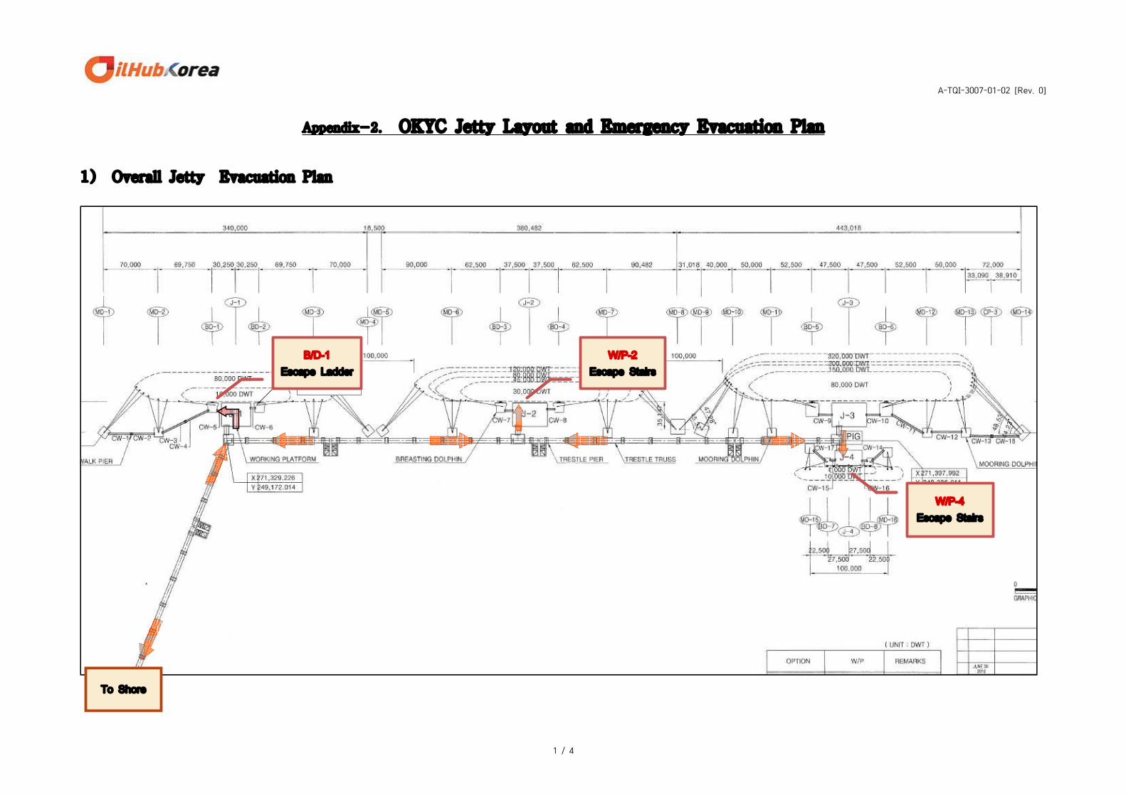
Appendix-2. OKYC Jetty Layout and Emergency Evacuation Plan
1) Overall Jetty Evacuation Plan
W/P-4Escape Stairs
B/D-1Escape Ladder
W/P-2Escape Stairs
To Shore
A-TQI-3007-01-02 [Rev. 0]
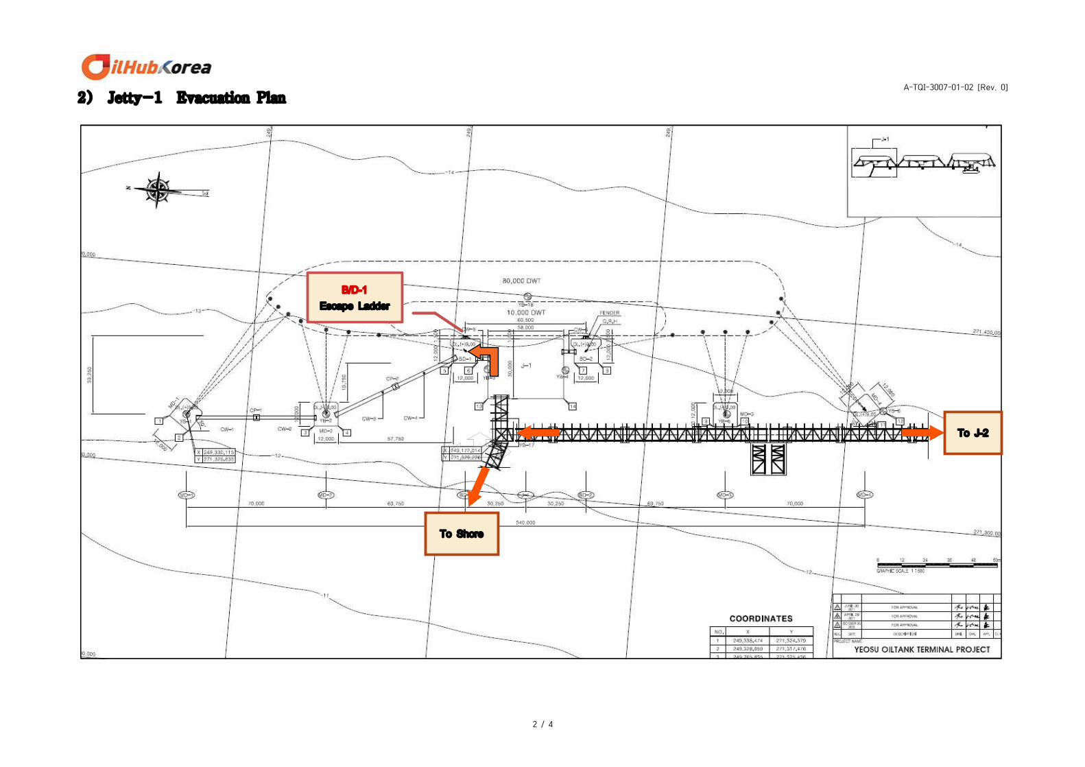
2 / 4
2) Jetty-1 Evacuation Plan
To Shore
B/D-1Escape Ladder
To J-2
A-TQI-3007-01-02 [Rev. 0]
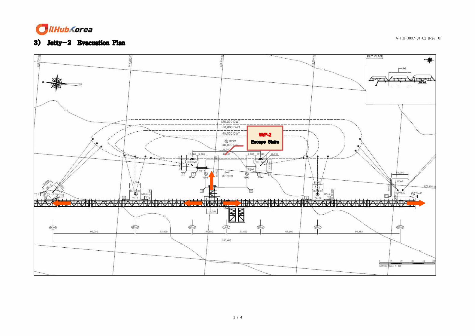
3 / 4
3) Jetty-2 Evacuation Plan
W/P-2Escape Stairs
A-TQI-3007-01-02 [Rev. 0]
4 / 4
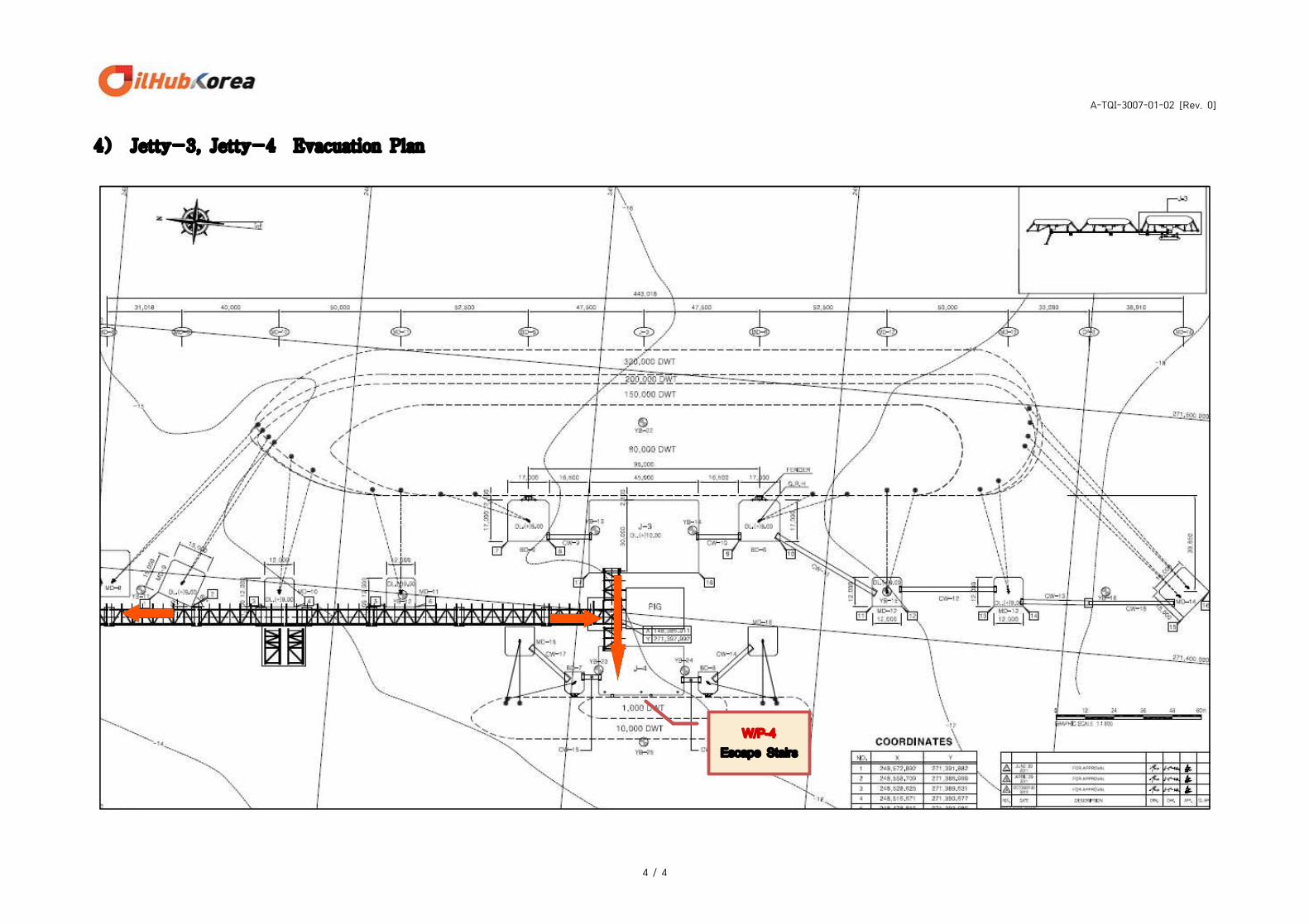
4) Jetty-3, Jetty-4 Evacuation Plan
W/P-4Escape Stairs
A-TQI-3007-01-03 [Rev. 0]
Appendix-3. Switch Loading Guideline
page 1 / 2
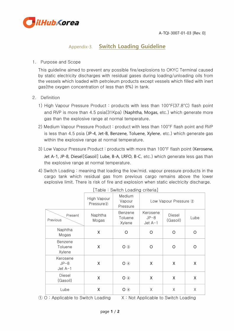
1. Purpose and Scope
This guideline aimed to prevent any possible fire/explosions to OKYC Terminal caused
by static electricity discharges with residual gases during loading/unloading oils from
the vessels which loaded with petroleum products except vessels which filled with inert
gas(the oxygen concentration of less than 8%) in tank.
2. Definition
1) High Vapour Pressure Product : products with less than 100°F(37.8°C) flash point
and RVP is more than 4.5 psia(31Kpa) (Naphtha, Mogas, etc.) which generate more
gas than the explosive range at normal temperature.
2) Medium Vapour Pressure Product : product with less than 100°F flash point and RVP
is less than 4.5 psia (JP-4, Jet-B, Benzene, Toluene, Xylene, etc.) which generate gas
within the explosive range at normal temperature.
3) Low Vapour Pressure Product : products with more than 100°F flash point (Kerosene,
Jet A-1, JP-8, Diesel[Gasoil] Lube, B-A, LRFO, B-C, etc.) which generate less gas than
the explosive range at normal temperature.
4) Switch Loading : meaning that loading the low/mid. vapour pressure products in the
cargo tank which residual gas from previous cargo remains above the lower
explosive limit. There is risk of fire and explosion when static electricity discharge.
[Table : Switch Loading criteria]
High Vapour
Pressure②
Medium
Vapour
Pressure
Low Vapour Pressure ②
Present Previous
Naphtha
Mogas
Benzene
Toluene
Xylene
Kerosene
JP-8
Jet A-1
Diesel
(Gasoil) Lube
Naphtha
Mogas X O O O O
Benzene
Toluene
Xylene
X O ③ O O O
Kerosene
JP-8
Jet A-1
X O ④ X X X
Diesel
(Gasoil) X O ④ X X X
Lube X O ④ X X X
① O : Applicable to Switch Loading X : Not Applicable to Switch Loading

A-TQI-3007-01-03 [Rev. 0]
Appendix-3. Switch Loading Guideline
page 2 / 2
② If loading the Low Vapor Pressure Products at the condition of higher than the flash
point temperature or loading the High Vapour Pressure Products at the condition of
low temperature (-15℃ or less), it should be considered as the Medium Vapour
Pressure Products because of its possibility to generate the gas within the explosive
range.
③ If in case of loading BTX cargo same as previous voyage, the 1) item of “Drying/Gas
Freeing“ at Section 3.2.3 do not need to be carried out.
④ In case that residual gas from the previous voyage remains less than the explosive
range at normal temperature, the Medium Vapour Pressure Products generates the
gas within the explosive range during loading, so it should be considered as the
Switch Loading.
⑤ Reference
- Chevron Field manual – Guide to Fire Protection
- API RP 2003 – Protection against Arising out of Static, Lightning, and Stray
Currents
GS-Caltex Product Wharf Standard Safety Manual – Switch Loading
3. Procedure
1) Any vessels which applicable to the Switch Loading shall carry out the Drying/Gas
Freeing prior to loading cargos and any crews are prohibited to enter the cargo tanks
until confirmation of safety by measuring gas/oxygen content (Gas content: less
than 15% of LEL, Oxygen content: more than 20%).
2) Vessels must establish loading plan for each cargo/tank and carry out appropriate
safety measures prior to berthing, and shall notify them to OKYC terminal. Terminal
staff shall confirm the loading plan along with the safety measures.
3) Shall check/record whether the product is Switch Loading or not as well as
notification about compliance with safety rules and regulations during ship/shore
safety meeting.
4) Shall check the content of flammable gas (at least less than 15% of the LEL) in the
cargo tanks which applicable Switch Loading prior to loading operation (cross-
check between ship/shore).
5) Shall carry out initial rate loading (initial loading rate : below than 1m/sec) for all
cargo tanks which applicable Switch Loading until Bell Mouth is submerged
completely.
6) Metal equipment is not allowed to use for dipping, gauging and sampling cargo for
30 minutes after completion of loading, and material of rope, which is used for the
above, should be made of natural fibers and prohibited to use synthetic fibers (nylon,
polypropylene, etc.).
7) Vessels shall record the above No.1) ~ 5) items.

A-TQI-3007-01-04 [Rev. 0]
Appendix-4. Vapour Emission Control Plan To the Master
Please duly arrange ship’s vapour return system as following;
1. Vessel's Preparation
1) Prior to berthing
① Keeping proper positive pressure(+500mmH2O) and fully inerted condition
(Oxygen content : Less than 8% by volume) ② Following devices are to be in good order and operational condition
- Vapor monitoring systems including vapor pressure gauges - Pressure safety devices such as P/V, breather valves, P/V breaker - Vent valves such as IG branch valves and associated valves ③ Ready for use of vapor return line - Free up port & starboard-side VOC manifold flanges - Clean up scales or any articles inside of vapor return pipeline - Remove the condensate water inside of pipes by draining appropriately
2) After Berthing
① Blowing out at ship's VOC manifold to check any foreign body inside of IG deck pipeline in presence of the loading master before connecting terminal VOC loading Arm
② Reduce tank pressure to about 100mmH2O to remove any foreign body inside IG deck pipeline via ship’s mast riser
3) Items to be discussed while Ship/Shore Safety Meeting
① Make sure of max. loading/flow rate per an hour ⇒
② Normal working vapor pressure on board ⇒
(In consideration of present vessel's setting limits) ③ Shore setting pressure based on above ②
④ To keep closed loading overall (If vessel can maintain closed loading even in gauging and sampling) ⑤ Open/Check manifold drain every 2 hr and gathering drainage. ⑥ Check hydro-carbon gas concentration every 2 hr at vapour manifold
(if requested by Loading Master)
2. Notice to Vessel's Master
1) Vessel should render full cooperation to protect Terminal DSU(Dock Safety Unit) through above Item 1. “Vessel's Preparation 1)~3)”.
2) In case of any delays, costs, expenses and consequential loss that we and/or
any third party may suffer by ship's foreign body, such as moisture, scales, and/or soot, among ship's gas inside of IG Deck Pipeline, We will issue our protest holding you responsible for all consequent problems.
Thanks for your kind cooperation
A-TQI-3007-01-05 [Rev. 0]
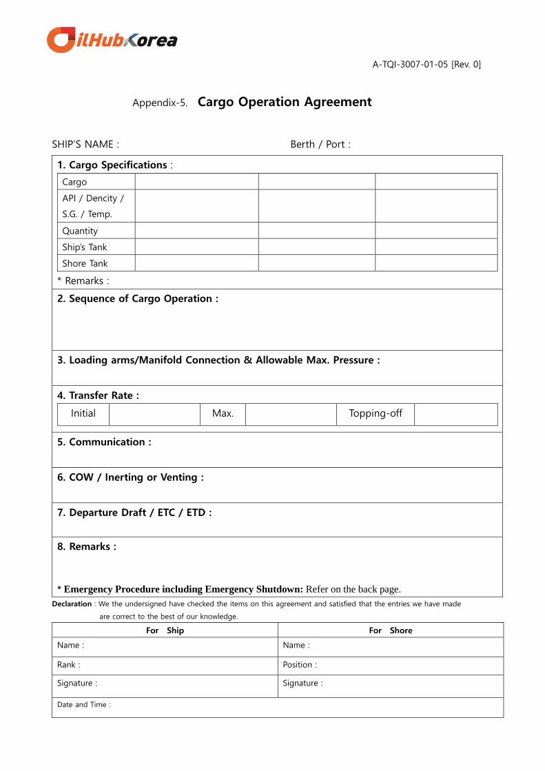
Appendix-5. Cargo Operation Agreement
SHIP’S NAME : Berth / Port :
1. Cargo Specifications :
Cargo
API / Dencity /
S.G. / Temp.
Quantity
Ship’s Tank
Shore Tank
* Remarks :
2. Sequence of Cargo Operation :
3. Loading arms/Manifold Connection & Allowable Max. Pressure :
4. Transfer Rate :
Initial Max. Topping-off
5. Communication :
6. COW / Inerting or Venting :
7. Departure Draft / ETC / ETD :
8. Remarks :
* Emergency Procedure including Emergency Shutdown: Refer on the back page. Declaration : We the undersigned have checked the items on this agreement and satisfied that the entries we have made
are correct to the best of our knowledge.
For Ship For Shore
Name : Name :
Rank : Position :
Signature : Signature :
Date and Time :

A-TQI-3007-01-05 [Rev. 0]
* Emergency Procedure
1. Emergency Signal
In the event of fire or other emergency, series of long blast (not less than 10 sec.) should be sounded by whistle or
siren.
2. Emergency Shutdown
In case the following circumstances, ship and terminal should take emergency shutdown cargo operation. Due regard
should be given to the possible dangers of pressure surge associated with any emergency shutdown procedure.
1) When weather forecast typhoon approaching or wind velocity increase more than 16m/sec.(10 min. average) or wave
(including swell) is higher than 1m.
2) When a fire breaks out or found oil spill around vessel(s).
3) When terminal representative has determined that it is too dangerous to continue cargo operation due to breach of
safety regulation or other matters.
4) When an accident is occurred on board.
3. Emergency Loading Arm Disconnection
ERC(Emergency release coupling) is equipped on crude/F.O. loading arms of Jetty-2 and all loading arms of Jetty-3.
ERC makes possible to disconnect loading arms from the vessel in a short period on emergency case such as vessel
over-drifting from berth, earthquake, fire, and etc.
4. Emergency Evacuation
When a emergency case of big fire or explosion of vessel/terminal have been occurred or foreseen, all the people on
jetty/vessel must escape from the danger place through appropriate route as ‘OKYC Jetty Layout & Emergency
Evacuation Plan’ (Appendix-2. in Terminal Information & Reg.) with consideration of following measures.
1) To request help like rescue boat from out-jetty using portable radio and emergency contact list.
2) Use appropriate PPE like as life-jacket, life-ring, EEBD, breathing apparatus, etc.
3) In case of presence of toxic gas at the scene, refer to ‘Toxic Gas Safety Guideline’ (Appendix-9. In Terminal
Information & Reg.)
5. Emergency Measures and Notifications
When a fire of oil spill accident have been occurred on board, the master must take appropriate initial emergency
measure to control the emergency and inform the situation to terminal representative without delay. All the cargo,
ballasting and bunkering operation must be stopped immediately and oil in the loading arms should be drained out
to prepare disconnection. Main engine, steering gear, and all mooring equipments also should be ready to use.
F-TQI- 3007-01-06 [Rev. 1]
Page 1 / 6
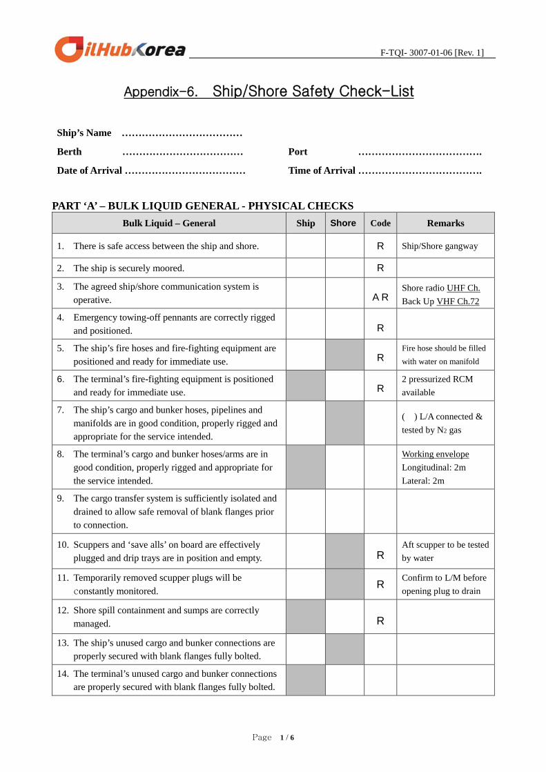
Appendix-6. Ship/Shore Safety Check-List
Ship’s Name ………………………………
Berth ……………………………… Port ……………………………….
Date of Arrival ……………………………… Time of Arrival ……………………………….
PART ‘A’ – BULK LIQUID GENERAL - PHYSICAL CHECKS Bulk Liquid – General Ship Shore Code Remarks
1. There is safe access between the ship and shore. R Ship/Shore gangway
2. The ship is securely moored. R
3. The agreed ship/shore communication system is operative. A R
Shore radio UHF Ch. Back Up VHF Ch.72
4. Emergency towing-off pennants are correctly rigged and positioned. R
5. The ship’s fire hoses and fire-fighting equipment are positioned and ready for immediate use. R
Fire hose should be filled with water on manifold
6. The terminal’s fire-fighting equipment is positioned and ready for immediate use. R
2 pressurized RCM available
7. The ship’s cargo and bunker hoses, pipelines and manifolds are in good condition, properly rigged and appropriate for the service intended.
( ) L/A connected & tested by N2 gas
8. The terminal’s cargo and bunker hoses/arms are in good condition, properly rigged and appropriate for the service intended.
Working envelope Longitudinal: 2m Lateral: 2m
9. The cargo transfer system is sufficiently isolated and drained to allow safe removal of blank flanges prior to connection.
10. Scuppers and ‘save alls’ on board are effectively plugged and drip trays are in position and empty. R
Aft scupper to be tested by water
11. Temporarily removed scupper plugs will be constantly monitored. R
Confirm to L/M before opening plug to drain
12. Shore spill containment and sumps are correctly managed. R
13. The ship’s unused cargo and bunker connections are properly secured with blank flanges fully bolted.
14. The terminal’s unused cargo and bunker connections are properly secured with blank flanges fully bolted.

F-TQI- 3007-01-06 [Rev. 1]
Page 2 / 6
15. All cargo, ballast and bunker tank lids are closed.
16. Sea and overboard discharge valves, when not in use, are closed and visibly secured. To be blanked
17. All external doors, ports and windows in the accommodation, stores and machinery spaces are closed. Engine room vents may be open.
R
Using external door; ________side ________deck
18. The ship’s emergency fire control plans are located externally. Location;.……………
If the ship is fitted, or is required to be fitted, with an Inert Gas System (IGS) the following points should be physically checked:
Inert Gas System Ship Shore Code Remarks
19. Fixed IGS pressure and oxygen content recorders are working.
R
20. All cargo tank atmospheres are at positive pressure with oxygen content of 8% or less by volume.
P R
PART ‘B’ – BULK LIQUID GENERAL – VERBAL VERIFICATION
Bulk Liquid – General Ship Shore Code Remarks
21. The ship is ready to move under its own power. P R with short notice
22. There is an effective deck watch in attendance on board and adequate supervision of operations on the ship and in the terminal.
R CCR: Manifold: Mooring tender:
23. There are sufficient personnel on board and ashore to deal with an emergency.
R More than 2/3 of crew on board at all times
24. The procedures for cargo, bunker and ballast handling have been agreed
A R Confirm to L/Master before operation start
25. The emergency signal and shutdown procedure to be used by ship and shore have been explained and understood
A Emergency Cargo Stop : 3 times Stop by Radio (General : Series of Long Blast)
26. Material Safety Data Sheets (MSDS) for the cargo transfer have been exchanged where requested. P R
27. The hazards associated with toxic substances in the cargo being handled have been identified and understood.
H2S: Benzene:
28. An International Shore Fire Connection has been provided.
29. The agreed tank venting system will be used. A R Method .............
30. The requirements for closed operations have been agreed. R
Ullaging: Sampling:
F-TQI- 3007-01-06 [Rev. 1]
Page 3 / 6
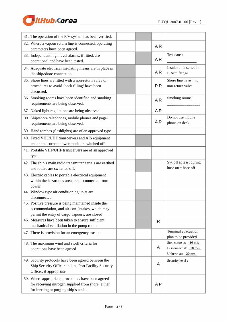
31. The operation of the P/V system has been verified.
32. Where a vapour return line is connected, operating parameters have been agreed.
A R
33. Independent high level alarms, if fitted, are operational and have been tested.
A R
Test date :
34. Adequate electrical insulating means are in place in the ship/shore connection.
A R
Insulation inserted in L/Arm flange
35. Shore lines are fitted with a non-return valve or procedures to avoid ‘back filling’ have been discussed.
P R
Shore line have no non-return valve
36. Smoking rooms have been identified and smoking requirements are being observed.
A R Smoking rooms:
................................. 37. Naked light regulations are being observed. A R
38. Ship/shore telephones, mobile phones and pager requirements are being observed.
A R
Do not use mobile phone on deck
39. Hand torches (flashlights) are of an approved type.
40. Fixed VHF/UHF transceivers and AIS equipment are on the correct power mode or switched off.
41. Portable VHF/UHF transceivers are of an approved type.
42. The ship’s main radio transmitter aerials are earthed and radars are switched off.
Sw. off at least during hose on ~ hose off
43. Electric cables to portable electrical equipment within the hazardous area are disconnected from power.
44. Window type air conditioning units are disconnected.
45. Positive pressure is being maintained inside the accommodation, and air-con. intakes, which may permit the entry of cargo vapours, are closed
46. Measures have been taken to ensure sufficient mechanical ventilation in the pump room
R
47. There is provision for an emergency escape. Terminal evacuation plan to be provided
48. The maximum wind and swell criteria for operations have been agreed.
A
Stop cargo at: 16 m/s Disconnect at: 18 m/s Unberth at: 20 m/s
49. Security protocols have been agreed between the Ship Security Officer and the Port Facility Security Officer, if appropriate.
A
Security level :
50. Where appropriate, procedures have been agreed for receiving nitrogen supplied from shore, either for inerting or purging ship’s tanks.
A P

F-TQI- 3007-01-06 [Rev. 1]
Page 4 / 6
If the ship is fitted, or is required to be fitted, with an Inert Gas System (IGS) the following statements should be addressed.
Inert Gas System Ship Shore Code Remarks
51. The IGS is fully operational and in good working order. P
52. Deck seals, or equivalent, are in good working order. R
53. Liquid levels in pressure/vacuum breakers are correct. R 54. The fixed and portable oxygen analysers have been
calibrated and are working properly. R
55. All the individual tank IGS valves (if fitted) are correctly set and locked.
R
56. All personnel in charge of cargo operations are aware that in the case of failure of the Inert Gas Plant, discharge operations should cease, and the terminal be advised.
If the ship is fitted with a Crude Oil Washing (COW) system, and intends to crude oil washing, the following statements should be addressed.
Crude Oil Washing Ship Shore Code Remarks 57. The Pre-Arrival COW check list, as contained in the
approved COW manual, has been satisfactorily completed.
58. The COW check lists for use before, during and after COW, as contained in the approved COW manual, are available and being used.
R
If the ship is planning to tank clean alongside, the following statements should be addressed.
Tank Cleaning Ship Shore Code Remarks 59. Tank cleaning operations are planned during the ship’s
stay alongside the shore installation. Yes/No* Yes/No* No allowed at the
berth 60. If ‘yes’ the procedures and approvals for tank cleaning have
been agreed.
61. Permission has been granted for gas freeing operations. Yes/No* Yes/No*
• Delete Yes or No as appropriate PART ‘C’ – BULK LIQUID CHEMICALS - VERBAL VERIFICATION
Bulk Liquid – Chemicals Ship Shore Code Remarks 1. Material Safety Data Sheets are available giving the
necessary data for the safe handling of the cargo.
2. A manufacturer’s inhibition certificate, where applicable, has been provided.
P
3. Sufficient protective clothing and equipment is ready for immediate use and is suitable for the product being handled.

F-TQI- 3007-01-06 [Rev. 1]
Page 5 / 6
4. Counter measures against accidental personal contact with the cargo have been agreed.
5. The cargo handling rate is compatible with the automatic shut down system, if in use.
A
6. Cargo system gauges and alarms are correctly set and in good order.
7. Portable vapour detection instruments are readily available for the products being handled.
8. Information on fire-fighting media and procedures has been exchanged.
9. Transfer hoses are of suitable material, resistant to the action of the products being handled.
10. Cargo handling is being performed with the permanent installed pipeline system.
P
11. Where appropriate, procedures have been agreed for receiving nitrogen supplied from shore, either for inerting or purging ship’s tanks, or for line clearing into the ship.
A P
DECLARATION
We, the undersigned, have checked the above items in Parts A and B, and where appropriate, Part C or D, in accordance with the instructions and have satisfied ourselves that the entries we have made are correct to the best of our knowledge.
We have also made arrangements to carry out repetitive checks as necessary and agreed that those items coded ‘R’ in the Check List should be re-checked at intervals not exceeding _______ hours.
If to our knowledge the status of any item changes, we will immediately inform the other party.
For Ship
Name ______________________________
Rank ______________________________
Signature ______________________________
Date ______________________________
Time _______________________________
For Shore
Name ______________________________
Position ______________________________
Signature ______________________________
Date ______________________________
Time ___________________________
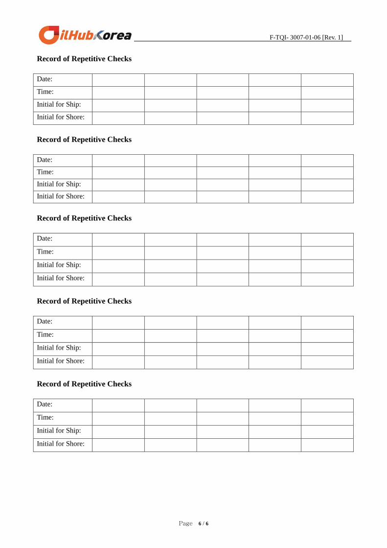
Record of Repetitive Checks
Date:
Time:
Initial for Ship:
Initial for Shore:
F-TQI- 3007-01-06 [Rev. 1]
Page 6 / 6
Record of Repetitive Checks
Date:
Time:
Initial for Ship:
Initial for Shore:
Record of Repetitive Checks
Date:
Time:
Initial for Ship:
Initial for Shore:
Record of Repetitive Checks
Date:
Time:
Initial for Ship:
Initial for Shore:
Record of Repetitive Checks
Date:
Time:
Initial for Ship:
Initial for Shore:
Record of Repetitive Checks
Date:
Time:
Initial for Ship:
Initial for Shore:
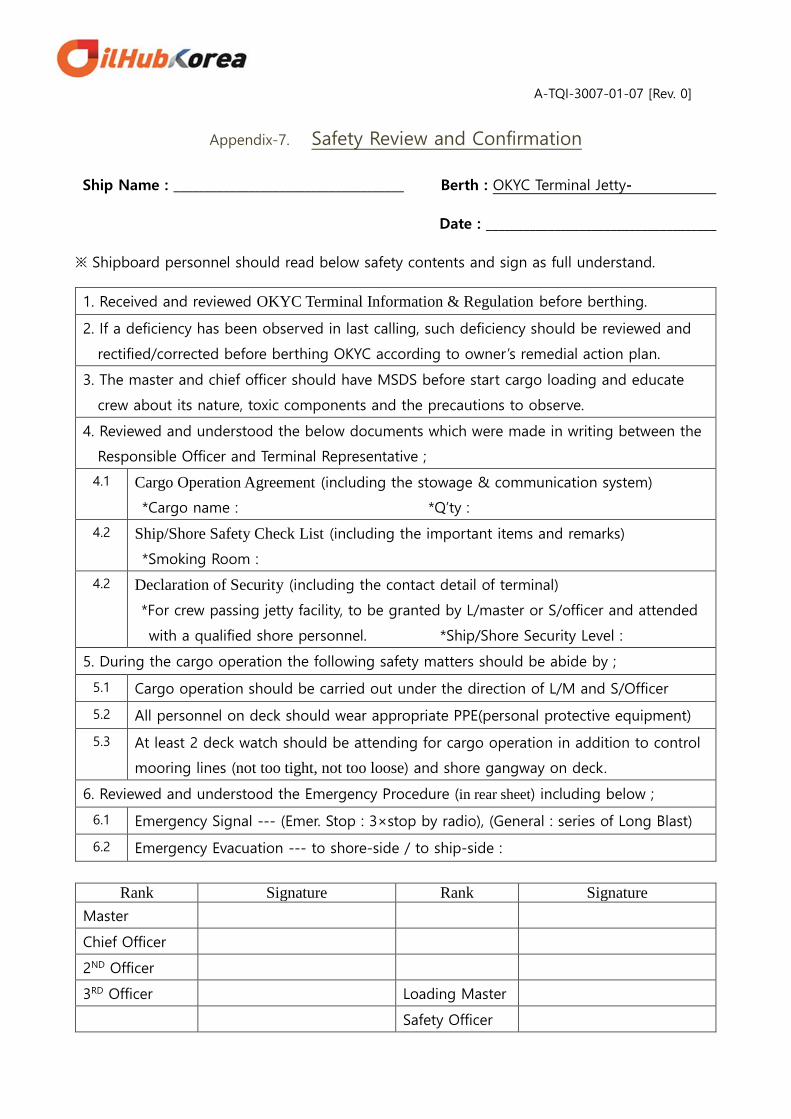
A-TQI-3007-01-07 [Rev. 0]
Appendix-7. Safety Review and Confirmation
Ship Name : _____________________________________ Berth : OKYC Terminal Jetty-
Date : _____________________________________
※ Shipboard personnel should read below safety contents and sign as full understand.
1. Received and reviewed OKYC Terminal Information & Regulation before berthing.
2. If a deficiency has been observed in last calling, such deficiency should be reviewed and
rectified/corrected before berthing OKYC according to owner’s remedial action plan.
3. The master and chief officer should have MSDS before start cargo loading and educate
crew about its nature, toxic components and the precautions to observe.
4. Reviewed and understood the below documents which were made in writing between the
Responsible Officer and Terminal Representative ;
4.1 Cargo Operation Agreement (including the stowage & communication system)
*Cargo name : *Q’ty :
4.2 Ship/Shore Safety Check List (including the important items and remarks)
*Smoking Room :
4.2 Declaration of Security (including the contact detail of terminal)
*For crew passing jetty facility, to be granted by L/master or S/officer and attended
with a qualified shore personnel. *Ship/Shore Security Level :
5. During the cargo operation the following safety matters should be abide by ;
5.1 Cargo operation should be carried out under the direction of L/M and S/Officer
5.2 All personnel on deck should wear appropriate PPE(personal protective equipment)
5.3 At least 2 deck watch should be attending for cargo operation in addition to control
mooring lines (not too tight, not too loose) and shore gangway on deck.
6. Reviewed and understood the Emergency Procedure (in rear sheet) including below ;
6.1 Emergency Signal --- (Emer. Stop : 3×stop by radio), (General : series of Long Blast)
6.2 Emergency Evacuation --- to shore-side / to ship-side :
Rank Signature Rank Signature Master
Chief Officer
2ND Officer
3RD Officer Loading Master
Safety Officer
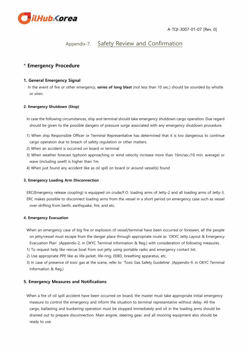
A-TQI-3007-01-07 [Rev. 0]
Appendix-7. Safety Review and Confirmation
* Emergency Procedure
1. General Emergency Signal
In the event of fire or other emergency, series of long blast (not less than 10 sec.) should be sounded by whistle
or siren.
2. Emergency Shutdown (Stop)
In case the following circumstances, ship and terminal should take emergency shutdown cargo operation. Due regard
should be given to the possible dangers of pressure surge associated with any emergency shutdown procedure.
1) When ship Responsible Officer or Terminal Representative has determined that it is too dangerous to continue
cargo operation due to breach of safety regulation or other matters.
2) When an accident is occurred on board or terminal
3) When weather forecast typhoon approaching or wind velocity increase more than 16m/sec.(10 min. average) or
wave (including swell) is higher than 1m.
4) When just found any accident like as oil spill on board or around vessel(s) found
3. Emergency Loading Arm Disconnection
ERC(Emergency release coupling) is equipped on crude/F.O. loading arms of Jetty-2 and all loading arms of Jetty-3.
ERC makes possible to disconnect loading arms from the vessel in a short period on emergency case such as vessel
over-drifting from berth, earthquake, fire, and etc.
4. Emergency Evacuation
When an emergency case of big fire or explosion of vessel/terminal have been occurred or foreseen, all the people
on jetty/vessel must escape from the danger place through appropriate route as ‘OKYC Jetty Layout & Emergency
Evacuation Plan’ (Appendix-2. in OKYC Terminal Information & Reg.) with consideration of following measures.
1) To request help like rescue boat from out-jetty using portable radio and emergency contact list.
2) Use appropriate PPE like as life-jacket, life-ring, EEBD, breathing apparatus, etc.
3) In case of presence of toxic gas at the scene, refer to ‘Toxic Gas Safety Guideline’ (Appendix-9. in OKYC Terminal
Information & Reg.)
5. Emergency Measures and Notifications
When a fire of oil spill accident have been occurred on board, the master must take appropriate initial emergency
measure to control the emergency and inform the situation to terminal representative without delay. All the
cargo, ballasting and bunkering operation must be stopped immediately and oil in the loading arms should be
drained out to prepare disconnection. Main engine, steering gear, and all mooring equipment also should be
ready to use.

Appendix-8 F-TQI-3007-01-08 [Rev. 1]
페이지 1 / 2
`Please check, test and/or carry out following items and report the results at least 3 day prior to
arrival (in case of short voyage, soonest) at OKYC terminal via your agent in Korea.
--------------------------------------------------------------------------------------------------------------
To : Berth master of OKYC Terminal
From : Master of Date :
CHECK LIST BEFORE ARRIVAL AT OKYC TERMINAL
No. Items Result
1. GENERAL
1.1 OKYC Terminal Information & Reg. to be fully understand :
1.2 Ship’s Displacement on arrival at OKYC Terminal : (ton)
1.3 The deepest draft during berthing and sailing (fwd/aft) :
2. ANTI POLLUTION
2.1 All sea water pumps & associated lines including scrubber and bilge
overboard discharge lines to be flushed and/or cleaned :
2.2 All bilge/slop valves in E/R and P/R to be closed and lashed :
2.3 Cargo sea-chest and/or ODME overboard line to be blanked :
2.4 On deck to be clean without any oil stains especially on winch beds :
2.5 Rudder post stuffing box and stern tube sealing to be good in order
without any oil leaks:
2.6 Main/aux. engine and boiler to be tested and prepared in good
condition to prevent emitting black smoke from funnel :
2.7 All scuppers to be plugged completely and proven water tight :
2.8 If VOC cargo loading, the preparation for vapor return line to be
carried out as per Appendix-4. Vapor Emission Control Plan :
3. MOORING LINE and MOORING WINCH
3.1 Mooring winches to be in good condition without any malfunction :
3.2 Winch brake holding condition to be in good working :
3.3 Mooring ropes to be in good condition :
3.4 If in case of mooring wires, fiber tails and links to be in good
condition with sufficient strength :
3.5 Distance between the center of manifolds to connect and fwd/aft
closed chock for spring line : (mtr.)
fwd:
aft :
3.6 Please attach ship’s Mooring Diagram or General Arrangement
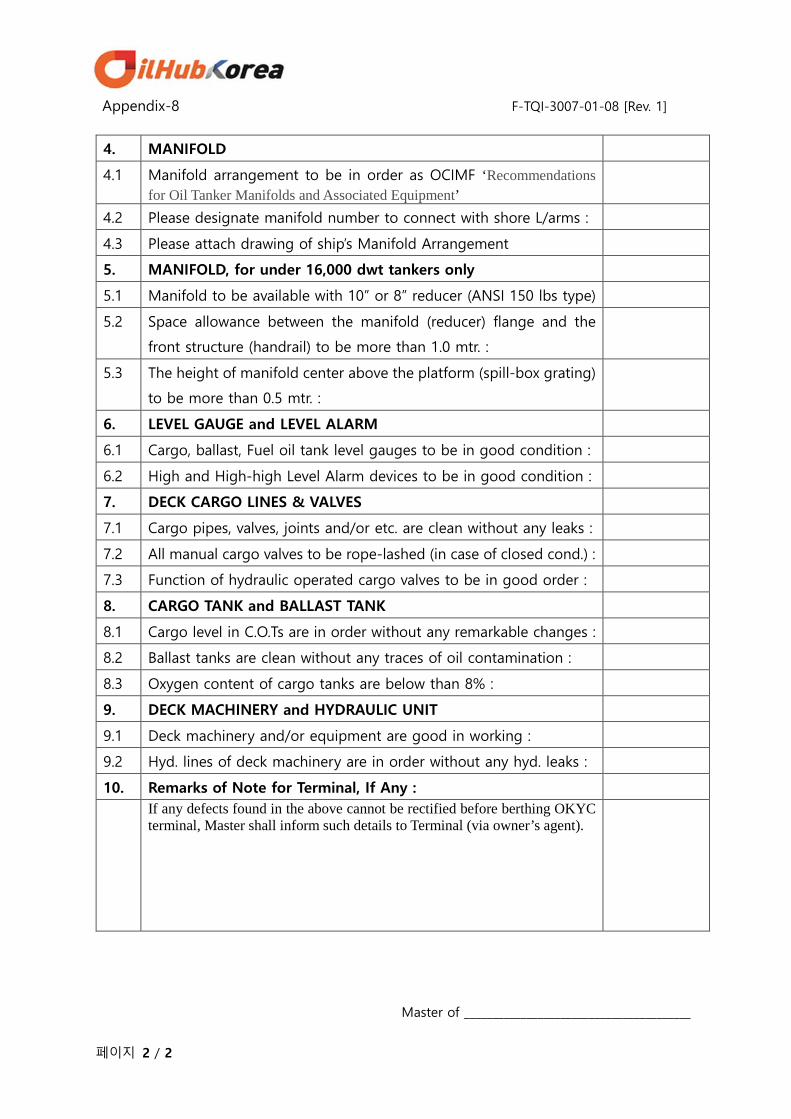
Appendix-8 F-TQI-3007-01-08 [Rev. 1]
페이지 2 / 2
4. MANIFOLD
4.1 Manifold arrangement to be in order as OCIMF ‘Recommendations for Oil Tanker Manifolds and Associated Equipment’
4.2 Please designate manifold number to connect with shore L/arms :
4.3 Please attach drawing of ship’s Manifold Arrangement
5. MANIFOLD, for under 16,000 dwt tankers only
5.1 Manifold to be available with 10” or 8” reducer (ANSI 150 lbs type)
5.2 Space allowance between the manifold (reducer) flange and the
front structure (handrail) to be more than 1.0 mtr. :
5.3 The height of manifold center above the platform (spill-box grating)
to be more than 0.5 mtr. :
6. LEVEL GAUGE and LEVEL ALARM
6.1 Cargo, ballast, Fuel oil tank level gauges to be in good condition :
6.2 High and High-high Level Alarm devices to be in good condition :
7. DECK CARGO LINES & VALVES
7.1 Cargo pipes, valves, joints and/or etc. are clean without any leaks :
7.2 All manual cargo valves to be rope-lashed (in case of closed cond.) :
7.3 Function of hydraulic operated cargo valves to be in good order :
8. CARGO TANK and BALLAST TANK
8.1 Cargo level in C.O.Ts are in order without any remarkable changes :
8.2 Ballast tanks are clean without any traces of oil contamination :
8.3 Oxygen content of cargo tanks are below than 8% :
9. DECK MACHINERY and HYDRAULIC UNIT
9.1 Deck machinery and/or equipment are good in working :
9.2 Hyd. lines of deck machinery are in order without any hyd. leaks :
10. Remarks of Note for Terminal, If Any :
If any defects found in the above cannot be rectified before berthing OKYC terminal, Master shall inform such details to Terminal (via owner’s agent).
Master of ________________________________________

A-TQI-3007-01-09 [Rev. 0]
Appendix-9. Toxic Gas Safety Guideline
1 / 3
H2S Gas 1. General
H2S is a very toxic, corrosive, colorless, heavier than air (density 1.189) flammable gas with
distinctive odor of rotten eggs
2. Sources
Many crude oils, Naphtha, Fuel Oil, Bunker fuels, Gas Oils
3. Concentration and Exposure Limits
3.1 Exposure Limits --- 5 ppm over 8 hours (TLV-TWA)
3.2 Short Term Exposure Limit --- 10 ppm (15 min.)
3.3Typical effects of exposure to H2S
H2S Concentration
(ppm by vol. in air) Physiological Effects
0.1 ~ 0.5 ppm First detectable by smell.
10 ppm May cause some nausea, minimal eye irritation.
25 ppm Eye and respiratory tract irritation. Strong odor.
50 ~ 100 ppm
Sense of smell starts to break down.
Prolonged exposure to concentrations at 100 ppm induces a gradual
increase in the severity of these symptoms and death may occur after 4~48
hours exposure.
150 ppm Loss of sense of smell in 2~5 minutes.
350 ppm Could be fatal after 30 minutes’ inhalation.
700 ppm
Rapidly induces unconsciousness (few minutes) and death. Causes seizures,
loss of control of bowel and bladder. Breathing will stop and death will
result if not rescued promptly.
over 700 ppm Immediately fatal.
* Concentration in liquid expressed in ppm by weight
4. Safety Procedure
4.1 Vapor Monitoring
➀ Places of monitoring : Adjacent of gauging point, sampling point, leaking point, and
venting point of storing tanks which containing sulfur content.
② Personal H2S gas monitor to be used : when working in enclosed spaces, gauging,

A-TQI-3007-01-09 [Rev. 0]
Appendix-9. Toxic Gas Safety Guideline
2 / 3
sampling, entering a pump room, connecting & disconnecting loading arms, draining to
open containments if H2S concentrations could exceed the TLV-TWA.
③ Before work, suitable measure including smell, instrumentation, and detector tubes to be
used for detecting and measuring the concentration of gas in all work locations.
4.2 Use proper PPE
➀ To quickly use EEBD when expected to H2S exceed the TLV-TWA.
② To wear respiratory equipment when H2S vapor in excess of the TLV-TWA.
4.3 Precautions when loading cargoes containing H2S
➀ Preparing :
- Ensure that all cargo system including VCU is free of leaks and working well.
- Attach a warning tag to places where H2S gas is likely to generate.
- When a cargo safety meeting, notify the danger of H2S gas and caution and make
ship/shore agreement of safety plan including venting procedure.
② When loading :
- Closed loading procedures (using VCU in case of VOC cargo) should be used.
When VCU is not in use, if no wind or it blows towards accommodation, the loading
operation should be stopped .
- All doors and windows of vessel/terminal should be closed to avoid H2S gas.
- Visitors should be briefed the hazards of cargo and emergency procedures and
escorted to/from the safe place.
4.4 When handling cargoes with very high concentrations of H2S
[ This is applied in case of over 100 ppm of H2S in vapor space ]
① Whenever very high concentrations of H2S are likely to be present, all working personnel
should have a personal H2S gas monitor/alarm and also EEBD should be available (When
alarm activates, wear EEBD and leave the area to an upwind location – refer to OKYC
Emergency Plan)
② When H2S is known to be present with following activities, self-contained breathing
apparatus should be worn.
Open gauging and sampling
When removal blind plate to connect/disconnect hose or loading arm before and
after loading/discharging cargo oil
Cleaning Filters
When draining with an open container
When wiping the spilled oil
Benzene 1. General
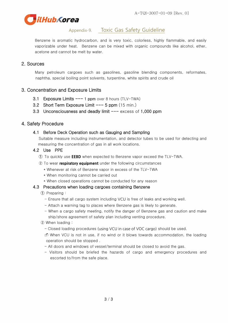
A-TQI-3007-01-09 [Rev. 0]
Appendix-9. Toxic Gas Safety Guideline
3 / 3
Benzene is aromatic hydrocarbon, and is very toxic, colorless, highly flammable, and easily
vaporizable under heat. Benzene can be mixed with organic compounds like alcohol, ether,
acetone and cannot be melt by water.
2. Sources
Many petroleum cargoes such as gasolines, gasoline blending components, reformates,
naphtha, special boiling point solvents, turpentine, white spirits and crude oil
3. Concentration and Exposure Limits
3.1 Exposure Limits --- 1 ppm over 8 hours (TLV-TWA)
3.2 Short Term Exposure Limit --- 5 ppm (15 min.)
3.3 Unconsciousness and deadly limit --- excess of 1,000 ppm
4. Safety Procedure
4.1 Before Deck Operation such as Gauging and Sampling
Suitable measure including instrumentation, and detector tubes to be used for detecting and
measuring the concentration of gas in all work locations.
4.2 Use PPE
➀ To quickly use EEBD when expected to Benzene vapor exceed the TLV-TWA.
② To wear respiratory equipment under the following circumstances
* Whenever at risk of Benzene vapor in excess of the TLV-TWA
* When monitoring cannot be carried out
* When closed operations cannot be conducted for any reason
4.3 Precautions when loading cargoes containing Benzene
➀ Preparing :
- Ensure that all cargo system including VCU is free of leaks and working well.
- Attach a warning tag to places where Benzene gas is likely to generate.
- When a cargo safety meeting, notify the danger of Benzene gas and caution and make
ship/shore agreement of safety plan including venting procedure.
② When loading :
- Closed loading procedures (using VCU in case of VOC cargo) should be used.
When VCU is not in use, if no wind or it blows towards accommodation, the loading
operation should be stopped .
- All doors and windows of vessel/terminal should be closed to avoid the gas.
- Visitors should be briefed the hazards of cargo and emergency procedures and
escorted to/from the safe place.

A-TQI-3007-01-10 [Rev. 1]
Appendix-10. OKYC Emergency Contact Detail
Yeosu Maritime Govern. Vessel Yeosu Marine Police
Office : 650-6000
Port Security : 650-6056
Terminal UHF ch.1
VHF ch.72
Mobile phone
24hr. office : 840-2000
VTS Center : 840-2552
Y. G. Port Authority Port Fire/Rescue Boat
Office : 797-4300
Yeosu branch : 692-4340
OKYC Terminal
Call sign : OK Terminal
Yeosu : 662-0119
Yeocheon : 684-0119
Main Control Room :
Yeosu City Hall 688-9166, 9119 City Emer. Response
Disaster : 690-2076
Environment : 690-2310
Jetty-1 : 688-9231
Jetty-2 : 688-9232
Jetty-3 : 688-9233
Jetty-4 : 688-9234
Disaster : 680-0800
Chemical Rescue : 680-0911
Emer. Towing Support Emergency Call KOEM (Oil-Spill Response)
Association : 665-1800
119
654-6431
KNOC Terminal Marine Casualty GS-Caltex Terminal
Operation : 688-8757
MCR : 688-8760
122
Environment : 680-2383
Crude Wharf : 680-2558
OKYC Terminal PFSO Terminal Berth Master : 688-9230
* In case of domestic call : Press 061 + Phone No.
* In case of oversea call : Press 82 + 61 + Phone No.
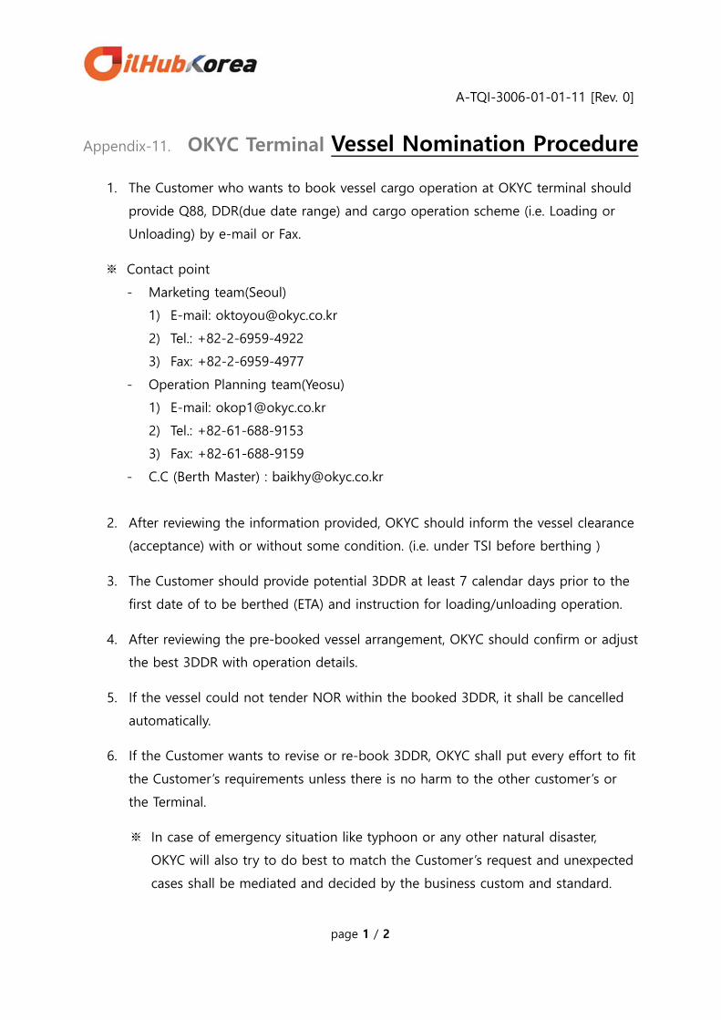
A-TQI-3006-01-01-11 [Rev. 0]
page 1 / 2
Appendix-11. OKYC Terminal Vessel Nomination Procedure
1. The Customer who wants to book vessel cargo operation at OKYC terminal should
provide Q88, DDR(due date range) and cargo operation scheme (i.e. Loading or
Unloading) by e-mail or Fax.
※ Contact point
- Marketing team(Seoul)
1) E-mail: [email protected]
2) Tel.: +82-2-6959-4922
3) Fax: +82-2-6959-4977
- Operation Planning team(Yeosu)
1) E-mail: [email protected]
2) Tel.: +82-61-688-9153
3) Fax: +82-61-688-9159
- C.C (Berth Master) : [email protected]
2. After reviewing the information provided, OKYC should inform the vessel clearance
(acceptance) with or without some condition. (i.e. under TSI before berthing )
3. The Customer should provide potential 3DDR at least 7 calendar days prior to the
first date of to be berthed (ETA) and instruction for loading/unloading operation.
4. After reviewing the pre-booked vessel arrangement, OKYC should confirm or adjust
the best 3DDR with operation details.
5. If the vessel could not tender NOR within the booked 3DDR, it shall be cancelled
automatically.
6. If the Customer wants to revise or re-book 3DDR, OKYC shall put every effort to fit
the Customer’s requirements unless there is no harm to the other customer’s or
the Terminal.
※ In case of emergency situation like typhoon or any other natural disaster,
OKYC will also try to do best to match the Customer’s request and unexpected
cases shall be mediated and decided by the business custom and standard.
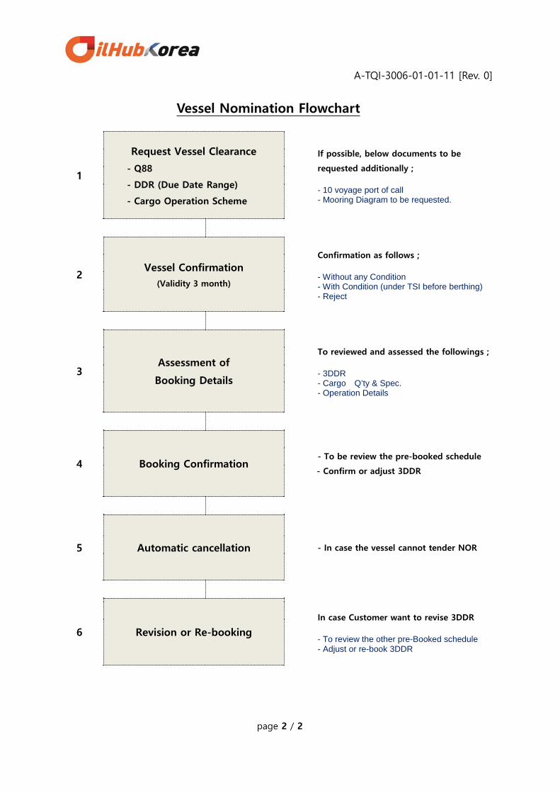
A-TQI-3006-01-01-11 [Rev. 0]
page 2 / 2
Vessel Nomination Flowchart
1
Request Vessel Clearance
- Q88
- DDR (Due Date Range)
- Cargo Operation Scheme
If possible, below documents to be
requested additionally ; - 10 voyage port of call - Mooring Diagram to be requested.
2 Vessel Confirmation
(Validity 3 month)
Confirmation as follows ; - Without any Condition - With Condition (under TSI before berthing) - Reject
3 Assessment of
Booking Details
To reviewed and assessed the followings ; - 3DDR - Cargo Q’ty & Spec. - Operation Details
4 Booking Confirmation
- To be review the pre-booked schedule
- Confirm or adjust 3DDR
5 Automatic cancellation
- In case the vessel cannot tender NOR
6 Revision or Re-booking
In case Customer want to revise 3DDR - To review the other pre-Booked schedule - Adjust or re-book 3DDR