o.k. karl dungs, nc. dmv-dle) 7../622 edition 216.8 p/n 26127 ul recognized component: file no....
TRANSCRIPT

1 … 8
MC
• Ka
rl D
ungs
, Inc
. • D
MV-
D(L
E) 7
../62
2 • E
ditio
n 20
16.0
8 • P
/N 2
6142
7
UL Recognized Component: File No. MH16727
CSA: CertifiedFileNo.157406
FM Approved: ReportJ.1.1Z6A0.AF
CommonwealthofMassachusettsApprovedProductApprovalcodeG1-1107-35
DMV-D(LE) 7../622Dual Safety Shutoff Valves with Proof of ClosureInstallation Instructions
Table of Contents
USA CDN
Table of Contents . . . . . . . . . . . . . . . . . . . . . . . . Page 1Approvals . . . . . . . . . . . . . . . . . . . . . . . . . . . . . . . Page 1Attention . . . . . . . . . . . . . . . . . . . . . . . . . . . . . . . . Page 1Specification . . . . . . . . . . . . . . . . . . . . . . . . . . . . Page 2Mounting. . . . . . . . . . . . . . . . . . . . . . . . . . . . . . . . Page3Painting Valve . . . . . . . . . . . . . . . . . . . . . . . . . . . Page3Protection from Radiant Heat . . . . . . . . . . . . . . Page4Wiring . . . . . . . . . . . . . . . . . . . . . . . . . . . . . . . . . . Page4Valve Adjustment. . . . . . . . . . . . . . . . . . . . . . . . . Page4Proof of Closure Switch . . . . . . . . . . . . . . . . . . . Page5Test Ports . . . . . . . . . . . . . . . . . . . . . . . . . . . . . . . Page5Valve Leakage Test . . . . . . . . . . . . . . . . . . . . . . . Page 6Flow Curve . . . . . . . . . . . . . . . . . . . . . . . . . . . . . . Page 7Pressure Drop for other Gases . . . . . . . . . . . . . Page 7Accessories & Replacement . . . . . . . . . . . . . . . Page 8
Approvals
1,2,3... =Action • =Instruction
Explanation of symbols
On completion of work on the safety valve, perform a leakage and function test.
Please read the instruction be-fore installing or operating. Keep the instruction in a safe place. You findtheinstructionalsoatwww.dungs.comIftheseinstructionsare not heeded, the result may be personal injury or damage to property.Any adjustment and application-specificadjustmentvaluesmustbe made in accordance with the appliance-/boiler manufacturers instructions.
Attention
Check the ratings in the speci-ficationstomakesurethattheyare suitable for your application.
IFGCCSAUL
ANSINFPA
This product is intended for installations covered by, but not limited to, the following fuel gas codes and standards: NFPA 54,IFGC(InternationalFuelGasCode),orCSAB149.1(forCana-da) or the following equipment codes and standards: CSD-1, UL795,NFPA86,NFPA37,ANSIZ83.4/CSA3.7,ANSIZ83.18,ANSIZ21.13/CSA4.9, orCSAB149.3(forCanada).
[V] [A] [Hz] [VA]
Safetyfirst
O.K.
The installation and maintenance of this product must be done under the supervision of an ex-perienced and trained specialist. Never perform work if gas pres-sure or power is applied, or in thepresenceofanopenflame.

2 … 8
MC
• Ka
rl D
ungs
, Inc
. • D
MV-
D(L
E) 7
../62
2 • E
ditio
n 20
16.0
8 • P
/N 2
6142
7
Specification
Max. Operating PressureMOP = 7 PSI (500 mbar)
Ambient Temperature-40 °F ... +150 °F(-40 °C … +65 °C)
Materials in contact with GasHousing: Aluminium, Steel, free of nonferrous metals. Sealings on valve seats: NBR-based rubber. max. 0.1 vol.% H2S, dry.
[PSI]
°F
0-40
+150
Gas
Electrical Ratings110 - 120 VAC / 50 - 60 Hz; 220 - 240 VAC / 50 - 60 Hz24 VAC / 50 - 60 Hz; 24 VDCOperating time100 % duty cycle
Strainer23 Mesh, installed in the housing upstream V1
Classification of Valve V1 and V2 Safety Shutoff Valve: UL 429, FM 7400ANSI Z21.21 • CSA 6.5 C/I ValvesClosingTime(Valve1&Valve2)< 1 sOpening Time DMV-D/622: V1 & V2 < 1 sDMV-DLE/622: V1< 1 s; V2 10 to 20 s at 70 °FMain Flow Setting (DMV-D/622&DMV-DLE/622)Adjustable on V2: <10 to 100 % of total flowInitialLiftAdjustment(DMV-DLE/622)Adjustable on V2: 0 to 70 % of total flowPosition Indication (optional forvalve 2 onlyVisual Indicator
DMV-D/622 Two normally closed safety shutoff valves in one housing. Fast opening, fast closing. Valve 2 features adjustable max. flow and proof of closure.
DMV-DLE/622 Two normally closed safety shutoff valves in one housing. Valve 1 fast opening, fast closing. Valve 2 slow opening, fast closing. Valve 2 features adjustable max. flow, adjustable initial lift and proof of closure.
[V] [A] [Hz] [VA]
NEMA
Enclosure RatingIP 65/NEMA Type 12
Electrical ConnectionDIN-connector (Order No. 210319) required. M20 - 1/2 NPT Adapter (Order No. 240671) required for a conduit connection. Order parts separately.
Additionally Required Electrical PartsDescription Order No.DIN Connector 210319Conduit Adapter 240671
3…8
MC
• Ka
rl D
ungs
, Inc
. • D
MV-
D(L
E) 7
../62
2 • E
ditio
n 20
16.0
8 • P
/N 2
6142
7
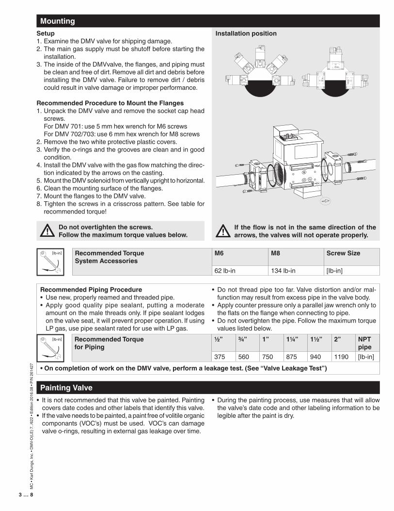
Mounting
Painting Valve
Setup1. Examine the DMV valve for shipping damage.2. The main gas supply must be shutoff before starting the
installation.3. The inside of the DMVvalve, the flanges, and piping must
be clean and free of dirt. Remove all dirt and debris before installing the DMV valve. Failure to remove dirt / debris could result in valve damage or improper performance.
Recommended Procedure to Mount the Flanges1. Unpack the DMV valve and remove the socket cap head
screws. For DMV 701: use 5 mm hex wrench for M6 screws For DMV 702/703: use 6 mm hex wrench for M8 screws 2. Remove the two white protective plastic covers.3. Verify the o-rings and the grooves are clean and in good
condition.4. Install the DMV valve with the gas flow matching the direc-
tion indicated by the arrows on the casting.5. Mount the DMV solenoid from vertically upright to horizontal.6. Clean the mounting surface of the flanges. 7. Mount the flanges to the DMV valve. 8. Tighten the screws in a crisscross pattern. See table for
recommended torque!
18
19
Chrome S
teel �
Mad
e in G
erman
y
[Ib-in]
Recommended Piping Procedure• Use new, properly reamed and threaded pipe.• Apply good quality pipe sealant, putting a moderate
amount on the male threads only. If pipe sealant lodges on the valve seat, it will prevent proper operation. If using LP gas, use pipe sealant rated for use with LP gas.
• OncompletionofworkontheDMVvalve,performaleakagetest.(See“ValveLeakageTest”)
• Do not thread pipe too far. Valve distortion and/or mal-function may result from excess pipe in the valve body.
• Apply counter pressure only a parallel jaw wrench only to the flats on the flange when connecting to pipe.
• Do not overtighten the pipe. Follow the maximum torque values listed below.
• It is not recommended that this valve be painted. Painting covers date codes and other labels that identify this valve.
• If the valve needs to be painted, a paint free of volitile organic componants (VOC’s) must be used. VOC’s can damage valve o-rings, resulting in external gas leakage over time.
• During the painting process, use measures that will allow the valve’s date code and other labeling information to be legible after the paint is dry.
Do not overtighten the screws. Follow the maximum torque values below.
Installationposition
Recommended Torque for Piping
1/2” 3/4” 1” 11/4” 11/2” 2” NPT pipe
375 560 750 875 940 1190 [Ib-in]
If theflowisnot in thesamedirectionof thearrows, the valves will not operate properly.
Recommended TorqueSystem Accessories
M6 M8 Screw Size
62 lb-in 134 lb-in [Ib-in]
18
19
Chrome S
teel �
Mad
e in G
erman
y
[Ib-in]

4…8
MC
• Ka
rl D
ungs
, Inc
. • D
MV-
D(L
E) 7
../62
2 • E
ditio
n 20
16.0
8 • P
/N 2
6142
7
Protection from Radiant Heat
Wiring
Valve Adjustment
Wiring the DMV/622• Disconnect all power to the valves before wiring to prevent
electrical shock and equipment damage.• Attach flexible 1/2” NPT conduit to the DIN connector.• Route 14 or 16 guage wire rated for at least 75 ˚C (167 ˚F)
through the conduit and the DIN connnector.• Connect the wiring to the appropriate screw terminals in
the DIN connector.• Plug the DIN connector onto the terminals. Fasten the DIN
connector with the screw supplied.
• Radiant heat must be considered as a heat source that could result in an ambient temperature higher than the rat-ing of this valve.
DINConnectorscrew terminal connections
Flow Setting• The valves are factory set with the flow adjustment fully
open.• CAUTION: Make sure the flow of gas does not create a
hazard.1. Locate the flow adjustment on top of valve 2 on the DMV-
D/622 (� black knob) DMV-DLE/622 (base of the hydraulic brake). There are two screws �, � the holding screw is recessed and has a blue sealing compound on it, while the pan head screw � protrudes from the cap.
2. Loosen the pan head screw � until you can freely rotate the flow adjustment �.
3. Turn clockwise for less gas or counterclockwise for more gas.
4. Check the flow at the burner with an orifice or flow meter.5. Tighten the pan head screw � on the adjustment cap �.
InitialLiftAdjustment(DMV-DLE/622only)The initial lift adjustment varies the initial gas flow through the valve as the valve seat begins to open. This adjustment can vary the initial flow between 0 % and 70 % of the total gas flow; 0 to 25 % of stroke. All DMV-DLE/6 valves are factory set with no initial lift. To adjust the lift proceed as follows:1. Unscrew the small black cap � on top of the flow adjust-
ment cap to expose the initial lift adjustment knob.2. The black cap � also serves as tool; turn the cap over and
insert it on the slot on the adjustment knob.3. Turn the knob � clockwise for a min. initial lift or counter-
clockwise for a max. initial lift.4. Once the desired initial fast lift has been achieved, reinstall
the black cap �.
� Mainflowadjustment knob
Initial lift adjustment
Hydraulic brake assembly (turn for main flow adjustment)
� �
�
�
��
• Provide proper shielding to protect against radiant heat.
All wiring must comply with local electrical codes, ordinances and regulations.
Do not adjust or remove any screws or bolts which are sealed with a Red or Blue colored
compound. Doing so will void all approvals and war-ranties.
- L2Neutral
Ground
+ L1HotValve 1
+ L1HotValve 2

5…8
MC
• Ka
rl D
ungs
, Inc
. • D
MV-
D(L
E) 7
../62
2 • E
ditio
n 20
16.0
8 • P
/N 2
6142
7
pmax.=7PSI
Test Ports
Proof of Closure Switch
L2 (N)
LocationThe proof of closure switch is factory installed on valve 2 of the DMV, it visually and electrically indicates valve position. When the valve is closed (NO position) an orange light is visible, when the valve is open (NC position) a green light is visible.Conduit Connection1. Before connecting conduit to the proof of closure switch,
position the proof of closure switch so that there is no torque from the wiring or conduit. If the switch needs to be rotated, loosen the slotted set screw on the side. The switch may be removed from the brass adapter for wiring, however, DO NOT turn the proof of closure switch after tightening the slotted set screw.
2. Tighten the slotted set screw so that the proof of closure switch housing is secure. (16 lb-in torque)
Wiring• Do not exceed the electrical ratings given in the proof of
closure switch specifications.• Use 14 or 16 guage wire for at least 167 °F (75 °C).• Connect wire to the appropriate terminal of the proof of
closure switch (see the wiring diagram). COM to the L1, Ground to ground, NO to the Proof of Clo-
sure terminal of the Flame Safeguard and N to L2. 3. The ORANGE light shall be on when the valve is closed, 4. The GREEN light shall be on when the valve is open (FM
requirement).
Annual Testing• Perform a switch continuity test at least annually to verify
that the proof of closure switch is working properly.1. Make sure that there is no power to the proof of closure
switch.2. Shut the upstream ball valve to stop the flow of gas into the
valve train.3. With the valve de-energized, use a multimeter and verify
that there is continuity between the switch contacts 3 (COM) and 2 (NO). Then verify that there is no continuity between the switch contacts 3 (COM) and 1 (NC).
4. Energize the valve that the proof of closure switch is mounted to. Use a multimeter and verify that there is con-tinuity between the switch contacts 3 (COM) and 1 (NC). Then verify that there is no continuity between the switch contacts 3 (COM) and 2 (NO).
Ifyouexperienceaproblem,contactDUNGS.5. De-energize the valve and replace the cover on the proof
of closure switch.6. Open the upstream ball valve.
Test PortsThe G 1/8 ISO 228 taps are available on both sides upstream V1, between V1 and V2, downstream V2, and on both flanges. The G 1/8 test nipple (P/N 219008) can be screwed in any of these pressure tap ports.
SwitchSPDTSwitch ActionValve open: Switch in NC position, Green light on. Valve closed: Switch in NO position, Orange light on.Contact Rating10 A res, 8 FLA, 48 LRA @120 VAC EnclosureNEMA Type 4Ambient/Fluid Temperature -40 °F to 150 °F
Proof of Closure Switch Specifications
Do not wire the valve switch to close a circuit thatwilldirectlypoweranothersafetyshutoff
valve. Doing so could result in a safety valve being en-ergized and opened rather than remaining closed.
1
2 Proof Terminal
3L1; COM
L2N
Ground
1 Increment
Green
Orange
Red Wire
Yellow Wire
CPI 400
Made in GermanyClosed Position
Indicator

6 … 8
MC
• Ka
rl D
ungs
, Inc
. • D
MV-
D(L
E) 7
../62
2 • E
ditio
n 20
16.0
8 • P
/N 2
6142
7
Valve Leakage TestThis leak test procedure tests the external sealing and valve seat sealing capabilities of the DMV automatic safety shutoff valve. Only qualified personnel should perform this test.
It is required that this test be done on the initial system startup, and then repeated at least annually. Possibly more often de-pending on the application, environmental parameters, and the requirements of the authority having jurisdiction.
SetupThis test requires the following:A) Test nipples installed in the downstream pressure tap port
of each automatic safety shutoff valve to make the required 1/4” hose connection in step 4.
B) A transparent glass of water filled at least 1 inch from the bottom.
C) A proper leak test tube. An aluminum or copper 1/4” rigid tube with a 45˚ cut at the end that is then connected to a 1/4” flexible hose of some convenient length provides for a more accurate leakage measurement.
However, a 45˚ cut at the end of the 1/4” flexible hose will suf-fice, but it will not likely be as accurate as the rigid tube.
D) For detecting external leakages, an all purpose liquid leak detector solution is required.
Leak Test ProcedureUse the illustration below as a reference. 1. With the upstream ball valve open, the downstream ball
valve closed and both valves energized, apply an all pur-pose liquid leak detector solution to the “External Leak-age Test Areas” indicated in the illustration below, to any accessories mounted to the safety valve, and to all gas piping and gas components downstream the equipment isolation valve, and the inlet and outlet gas piping of the automatic safety shutoff valve. The presence of bubbles
indicates a leak, which needs to be rectified before pro-ceeding.
2. Then, de-energize the burner system and verify that both automatic safety shutoff valves are closed.
3. Close the upstream and downstream manual ball valve. 4. Using a screwdriver, slowly open the V1 test nipple (port 2)
by turning it counter clockwise to depressurize the volume between the two valves, and connect the 1/4” flexible hose to the test nipple.
5. Slowly open the upstream manual ball valve, and then pro-vide for some time to allow potential leakage to charge the test chamber before measuring the valve seat leakage.
6. Immerse the 1/4 in. tube vertically 1/2 in. (12.7 mm) below the water surface. If bubbles emerge from the 1/4” tube and after the leakage rate has stabilized, count the number of bubbles appearing during a 10 second period. (See chart below for allowable leakage rates.)
7. Repeat the same procedure for valve V2 (port 3). (Energize terminal 2 on the DIN connector to open valve 1)
After completing the above tests proceed as follows: 8. Verify that the downstream manual ball valve is closed,
and both automatic safety shutoff valves are de-ener-gized.
9. Remove the flexible hose, and close all test nipples. 10. With the upstream manual ball valve open, energize both
automatic safety shutoff valves.11. Use soapy water to leak test all test nipples to ensure that
there are no leaks.12. If no leakage is detected, de-energize all automatic safety
shutoff valves, and open the downstream manual ball valve.
que
65 in
. Lbs
M.
(see step 1)Leak Test Here
Type Allowable Valve Seat #ofBubblesin10sLeakage*upto7PSIinlet Air Natural Gas LP
DMV D(LE) 701/622 239 cc/hr 5 6 4DMV-D(LE) 702/622 464 cc/hr 9 11 7DMV-D(LE) 703/622 464 cc/hr 9 11 7*Based on air and test conditions per UL 429 Section 29. (Air or inert gas at a pressure of 1/4 psig and also at a pressure of one and one-half times maximum operating pressure differential, but not less than 1/2 psig. This test shall be applied with the valve installed in its intended position.)Volume of bubble defined in Table 2 of FCI 70-2-1998.
G 1/8“ Test Nipple # 219008
Port 2 Leak Test for V1Port 3 Leak Test for V2
1/4“ Flex Hose
1/4“ Rigid Tube
1/2“1“
Ifleakagevaluesareexceeded,replacevalveimmediately.

7 … 8
MC
• Ka
rl D
ungs
, Inc
. • D
MV-
D(L
E) 7
../62
2 • E
ditio
n 20
16.0
8 • P
/N 2
6142
7
Pressure Drop for other Gases
Flow Curve
To determine the pressure drop when using a gas other than natural gas, use the flow formula below and f value located in the table below to determine the “corrected” flow rate in CFH through the valve for the other gas used. For example,
when using propane, divide the volume (CFH) of propane required for the application by the calculated value f (f = 0.66 for propane). Use this “corrected” flow rate and the flow curve on the next page to determine pressure drop for propane.
Density of Natural gas
Density of gas usedf=
Type of gas Density[kg/m3] s.g. f
Natural gas 0.81 0.65 1.00Butane 2.39 1.95 0.58Propane 1.86 1.50 0.66Air 1.24 1.00 0.80
Determiningequivalentflowthroughvalvesusinganothergas
Vgas used = V Natural gas x f° °
Basedon60°F14.65psia,dry
Flow(CFH)ofnaturalgas;s.g.0.65at60°F
Pressuredrop(in.W.C.)

8 … 8
MC
• Ka
rl D
ungs
, Inc
. • D
MV-
D(L
E) 7
../62
2 • E
ditio
n 20
16.0
8 • P
/N 2
6142
7
Karl Dungs GmbH & Co. KGP.O.Box1229D-73602Schorndorf,GermanyPhone+49(0)7181-804-0Fax +49(0)7181-804-166e-mail [email protected]://www.dungs.com
KarlDungs,Inc.3890PheasantRidgeDriveNESuite150Blaine,MN55449,U.S.A.Phone763582-1700Fax 763582-1799e-mail [email protected]://www.dungs.com/usa/
Accessories & ReplacementCoil for Magnet
TypeOrder No. for 120VAC
Order No. for 24VAC
Order No. for 24VDC
DMV-D(LE) 701/602 1111 232401 238554 238829DMV-D(LE) 702/602 1211 232402 238825 238826DMV-D(LE) 703/602 1212 232403 238822 238823Printed Wiring Board Magnet
TypeDMV-D(LE) 701/602 1111 238803 238803 238804DMV-D(LE) 702/602 1211 238806 238806 238807DMV-D(LE) 703/602 1212 238806 238806 238807Accessories/Adapter Order No. DescriptionElectricalDINConnector(DUNGS)
210319
M20-1/2NPTAdapter 240671VisualIndicator 266949 The indicator mounts to the bottom of the valve and visually displays when
the valve is open or closed.ValveSwitchCPI400 266968 Valve switch with visual indication.1/4”NPTport1orport2adapter(reducedport)
225047
1/2”NPTport2pilot/ventadapter(reducedport)
225043
G1/8”Testnipplewithgasket 219008Port3pressureswitchmounting adapter
273777
Hydraulic Brake 240458Max. Flow Adj. Knob 240457
Valve Description Flange NPT P/N
RpP/N
O-ring and bolt kit P/N*
FRImountingKit P/N**
Integralstrainerand Filter replacement
DMV-701 1/2” 222371 222341 224093 219967 230440DMV-701 3/4” 222368 222342 224093 219967 230440DMV-701 1” 221999 222001 224093 219967 230440DMV-702 & 703 1” 222369 222343 224094 219968 230441DMV-702 & 703 1 1/4” 222370 222344 224094 219968 230441DMV-702 & 703 1 1/2” 222003 221884 224094 219968 230441DMV-702 & 703 2” 221997 221926 224094 219968 230441*Includes two o-rings and two sets of bolts (one set of four bolts for each flange).
**Includes four bolts and one o-ring.