oisd 149 draft iii
TRANSCRIPT

1
` OISD-RP-149 Draft-III FOR RESTRICTED CIRCULATION ONLY
DESIGN ASPECTS FOR SAFETY IN
ELECTRICAL SYSTEM
OISD - RECOMMENDED PRACTICES - 149 First Edition, February, 1996
Amended Edition, September 2001 Completely Revised Edition ------ 2011
Oil Industry Safety Directorate
Government of India Ministry of Petroleum & Natural Gas
Website: www.oisd.gov.in
2
OISD - RP - 149 First Edition, February, 1996
Amended Edition, September 2001 Second Edition,----------, 2011
FOR RESTRICTED
CIRCULATION ONLY
DESIGN ASPECTS FOR SAFETY IN
ELECTRICAL SYSTEM
Prepared by:
COMMITTEE ON “DESIGN ASPECTS FOR ELECTRICAL SAFETY”
OIL INDUSTRY SAFETY DIRECTORATE
7TH
FLOOR, NEW DELHI HOUSE
27, BARAKHAMBA ROAD
NEW DELHI – 110 001

3
NOTE OISD publications are prepared for use in the oil and gas industry
under Ministry of Petroleum and Natural Gas. These are the property of Ministry of Petroleum and Natural Gas and shall not be reproduced or copied and loaned or exhibited to others without written consent from OISD.
Though every effort has been made to assure the accuracy and
reliability of the data contained in these documents, OISD hereby expressly disclaims any liability or responsibility for loss or damage resulting from their use.
These documents are intended to supplement rather than
replace the prevailing statutory requirements.
Note 3 in the superscript indicates the modification/changes/addition based on the amendments approved in the 19
th Safety Council meeting
held in September, 2001July, 1999

4
FOREWORD
Oil Industry in India is nearly 100 years old. Due to various collaboration agreements a variety of international codes, standards and practices are in vogue, Standardisation in design philosophies, operating and maintenance practices at a national level was hardly in existence. This lack of uniformity coupled with feedback from some serious accidents that occurred in the recent past in India and abroad, emphasised the need for the industry to review the existing state of art in designing, operating and maintaining oil and gas installations.
With this in view, the Ministry of Petroleum and Natural Gas in 1986 constituted a
Safety Council assisted by the Oil Industry Safety Directorate (OISD) staffed from within the industry in formulating and implementing a series of self-regulatory measures aimed at removing obsolescence, standardising and upgrading the existing standards to ensure safer operations. Accordingly OISD constituted a number of functional committees comprising of experts nominated from the industry to draw up standards and guidelines on various subjects.
The present document on “Design Aspects for Safety in Electrical System” was
prepared by the Functional committee on “Design Aspects for Electrical Safety”. This document is based on the accumulated knowledge and experience of industry members and the various national and international codes and practices.
It is hoped that provisions of this document if implemented objectively, may go a
long way to improve the safety to reduce accidents in Oil and Gas Industry. Users are cautioned that no document can be a substitute for the judgement of responsible and experienced engineer.
Suggestions are invited from the users after it is put into practice to improve the
document further. Suggestions for amendments, if any, to this standard should be addressed to :
The Co-ordinator
Committee on “Design Aspects for Electrical Safety” OIL INDUSTRY SAFETY DIRECTORATE
7th
Floor, ‘New Delhi House’ 27, Barakhamba Road New Delhi – 110 001
This document in no way supersedes the statutory regulations of Chief Controller of Explosives (CCE), Factory Inspectorate or any other statutory body which must be followed as applicable.

5
COMMITTEE ON
DESIGN ASPECTS FOR ELECTRICAL SAFETY (First Edition – 1996)
---------------------------------------------------------------------------------------------------------------------------------
NAME ORGANISATION --------------------------------------------------------------------------------------------------------------------------------- LEADER Shri V. P. Sharma Engineers India Limited MEMBERS Shri R. Sankaran Madras Refineries Limited Shri U. P. Singh Indian Oil Corporation Limited Shri Narendra Kumar Gas Authority of India Limited Shri R. Raghupathy Engineers India Limited MEMBER CO-ORDINATORS Shri N. V. Mani Oil Industry Safety Directorate Shri J. K. Jha Oil Industry Safety Directorate ---------------------------------------------------------------------------------------------------------------------------------
In addition to the above, several other experts from Industry contributed in the preparation, review and finalisation of this document.
6
COMMITTEE ON
DESIGN ASPECTS FOR ELECTRICAL SAFETY (Second Edition – ------,2011)
---------------------------------------------------------------------------------------------------------------------------------
NAME ORGANISATION --------------------------------------------------------------------------------------------------------------------------------- LEADER Shri Niraj Sethi Engineers India Limited MEMBERS Shri Rampal Singh Bharat Petroleum Corporation Limited. Shri A K Khurana Indian Oil Corporation Limited (Pipelines Division) Shri D Kumar GAIL(India) Limited Shri A Sezhian Oil & Natural Gas Corporation Limited Shri A K Acharya Oil India Limited Shri V A Katne Hindustan Petroleum Corporation Limited Shri B B Brahma Indian Oil Corporation Limited (IOCL-BGR) Shri G R Dhingra Indian Oil Corporation Limited (RHQ) Shri P K Talukdar Numaligarh Refineries Limited Shri K G Prakash Mangalore Refinery & Petrochemicals Limited Shri R K Narula Centre for High Technology Shri C Jayaraman Bharat Petroleum Corporation Limited (Kochi Refinery) Shri P Mondal Bharat Petroleum Corporation Limited (Pipelines) Shri S K Sadhu Indian Oil Corporation Limited MEMBER CO-ORDINATORS Shri Y P Gulati Oil Industry Safety Directorate --------------------------------------------------------------------------------------------------------------------------------- In addition to the above, several other experts from Industry contributed in the preparation, review and finalisation of this document.

7
DESIGN ASPECTS FOR SAFETY IN ELECTRICAL SYSTEM
CONTENTS
------------------------------------------------------------------------------ SECTION DESCRIPTION ------------------------------------------------------------------------------- 1.0 INTRODUCTION 2.0 SCOPE 3.0 DEFINITIONS 4.0 POWER SYSTEM DESIGN 4.1 Capacity of Electrical Plant 4.2 Neutral Earthing 4.3 Short Circuit Capacities 4.4 Insulation Coordination 4.5 Protection and Metering 4.6 Emergency Power Supply 4.7 Critical Power Supply Systems 5.0 ELECTRICAL EQUIPMENT FOR CLASSIFIED AREA 6.0 SUB-STATION LOCATION/LAYOUT 7.0 ELECTRICAL EQUIPMENT 7.1 Characteristics 7.2 Equipment Features 7.2.1 Transformers 7.2.2 H.V/M.V Switchboards 7.2.3 Motors (H.V & M.V) 7.2.4 Battery Charger and Distribution Board 7.2.5 Batteries and Battery Accessories 7.2.6 Equipment for Uninterrupted Power Supply System 7.2.7 Capacitor Banks 7.2.8 Emergency Generator

8
------------------------------------------------------------------------------ SECTION DESCRIPTION ------------------------------------------------------------------------------- 7.2.9 Cables 7.2.10 Control Station 7.2.11 Convenience Receptacles 7.2.12 Actuators for Motor Operated Valves 8.0 PLANT CABLING 9.0 PLANT LIGHTING 10.0 PLANT EARTHING 11.0 PLANT SAFETY AND SECURITY SYSTEMS 11.1 Plant Fire Detection and Alarm System 11.2 Communication System 11.2.1 Telephone System 11.2.2 Public Address System 11.2.3 Emergency Communication System (Hot Line System) 11.2.4 Radio Communication System a) Portable Walkie-Talkie System b) VHF System 11.2.5 Fax System 12.0 MOBILE EQUIPMENT FOR HAZARDOUS AREAS 12.1 Portable Hand Lamps 12.2 Diesel Engines 12.3 Storage Batteries 12.4 Testing Equipment 12.5 Miscellaneous Requirements 12.6 Vehicles 13.0 REFERENCES =====================================================================

9
DESIGN ASPECTS FOR SAFETY IN ELECTRICAL SYSTEM
1.0 INTRODUCTION
Safety in electrical system draws maximum attention especially in the hydrocarbon industry, where classified hazardous atmosphere is encountered and electricity can constitute one of the sources of ignition for fire accidents and explosions. Besides equipment damage and property loss, electrical hazards can lead to injuries and fatalities to personnel due to electric shock and burns. The electrical system designer, hence, faces a challenge to provide a safe and reliable electrical system.
It is therefore imperative that safety aspects are built into the electrical system right from the design and engineering stage with the main objective of minimising equipment/system failure to prevent injury to personnel and damage to system components.
Following the guidelines and adhering to the safe practices given in this standard, would ensure adequate levels of safety in the electrical facilities of Oil Industry.
2.0 SCOPE
This document recommends minimum requirements in the design and engineering of electrical installations in Refineries, Gas Processing Plants and Cross country Pipeline Installations with or without storages.
This standard does not cover offshore installations and also the provisions of this standard do not apply to the following:
i. Petroleum Depots, Terminals, Central Tank Farms (CTF),Lube Oil Installations, Grease Manufacturing and Filling facilities.
ii. Onshore Drilling and Work over rigs which are covered in OISD-STD-216.
iii. E&P onshore Production installations (GGS/OCS, GCP/GCS, EPS, QPS/WH etc).
This standard is not intended for use as a comprehensive design
manual for electrical power system design. The standard in no way supersedes the statutory regulations of the Chief Electrical Inspectorate, Factory inspectorate, Chief Controller of Explosives, Director General Mines Safety, Central Electricity Authority or other Government bodies, which shall be followed as applicable.
3.0 DEFINITIONS
i) Earth Connection
A connection to the general mass of earth by means of an earth electrode. An object is said to be ‘earthed’ when it is electrically connected to an earth electrode; and a conductor is said to be ‘solidly earthed’ when it is electrically connected to earth electrode without a fuse, switch, circuit-breaker, resistance or impedance in the earth connection.
ii) Earth Continuity Conductor
The conductor, including any clamp, connecting to the earthing lead or to each other of those parts of an installation which are required to be earthed.
iii) Earth Electrode
A metal plate, pipe or other conductor embedded in the soil that makes a direct contact to the general mass of the earth.
iv) Earthing Lead
The final conductor by which the connection to the earth electrode is made.
v) Equipotential Bond Electrical connection maintaining various exposed conductive-parts and extraneous-conductive-parts at substantially the same potential.
vi) Voltage, Low - (LV)
The voltage which does not normally exceed 250 volts.
10
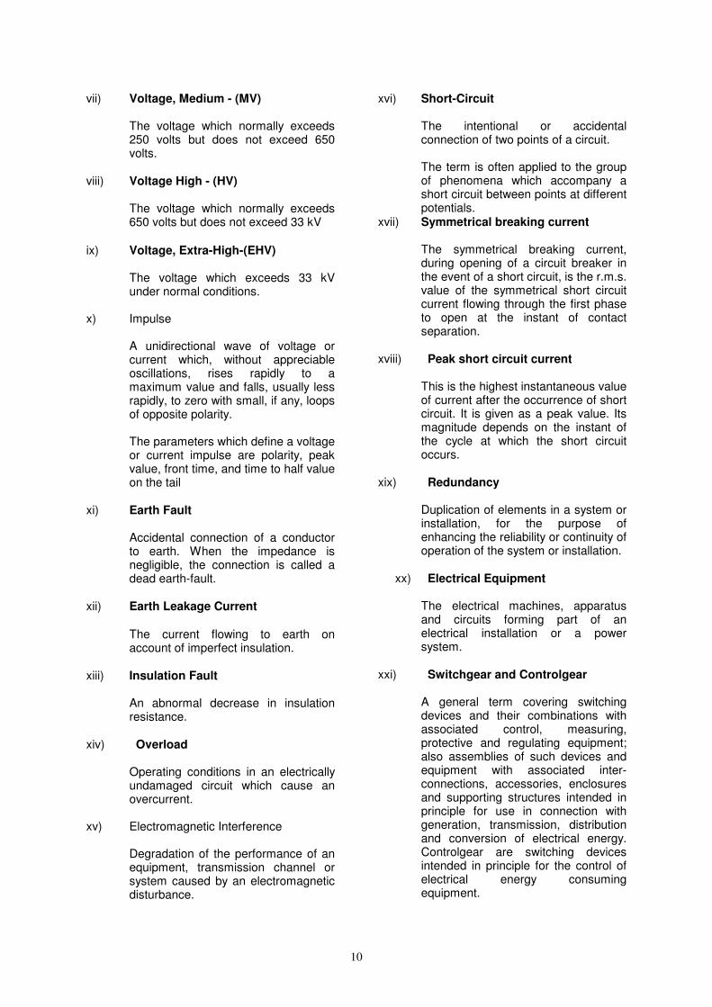
vii) Voltage, Medium - (MV)
The voltage which normally exceeds 250 volts but does not exceed 650 volts.
viii) Voltage High - (HV)
The voltage which normally exceeds 650 volts but does not exceed 33 kV
ix) Voltage, Extra-High-(EHV)
The voltage which exceeds 33 kV under normal conditions.
x) Impulse
A unidirectional wave of voltage or current which, without appreciable oscillations, rises rapidly to a maximum value and falls, usually less rapidly, to zero with small, if any, loops of opposite polarity. The parameters which define a voltage or current impulse are polarity, peak value, front time, and time to half value on the tail
xi) Earth Fault
Accidental connection of a conductor to earth. When the impedance is negligible, the connection is called a dead earth-fault.
xii) Earth Leakage Current
The current flowing to earth on account of imperfect insulation.
xiii) Insulation Fault
An abnormal decrease in insulation resistance.
xiv) Overload
Operating conditions in an electrically undamaged circuit which cause an overcurrent.
xv) Electromagnetic Interference
Degradation of the performance of an equipment, transmission channel or system caused by an electromagnetic disturbance.
xvi) Short-Circuit
The intentional or accidental connection of two points of a circuit. The term is often applied to the group of phenomena which accompany a short circuit between points at different potentials.
xvii) Symmetrical breaking current
The symmetrical breaking current, during opening of a circuit breaker in the event of a short circuit, is the r.m.s. value of the symmetrical short circuit current flowing through the first phase to open at the instant of contact separation.
xviii) Peak short circuit current
This is the highest instantaneous value of current after the occurrence of short circuit. It is given as a peak value. Its magnitude depends on the instant of the cycle at which the short circuit occurs.
xix) Redundancy
Duplication of elements in a system or installation, for the purpose of enhancing the reliability or continuity of operation of the system or installation.
xx) Electrical Equipment
The electrical machines, apparatus and circuits forming part of an electrical installation or a power system.
xxi) Switchgear and Controlgear
A general term covering switching devices and their combinations with associated control, measuring, protective and regulating equipment; also assemblies of such devices and equipment with associated inter-connections, accessories, enclosures and supporting structures intended in principle for use in connection with generation, transmission, distribution and conversion of electrical energy. Controlgear are switching devices intended in principle for the control of electrical energy consuming equipment.

11
xxii) Nominal Voltage (of an Installation)
Voltage for which an installation or part of an installation is designated.
xxiii) Highest System Voltage
The highest R.M.S. phase to phase voltage, which occurs under normal operating conditions at any time and at any point in the system. It excludes voltage transients (such as those due to system switching) and temporary voltage variation due to abnormal system conditions (such as those due to fault conditions on sudden disconnection of large loads).
xxiv) Lightning Protective System
The whole system of interconnected conductors used to protect a structure from the effects of lightning.
xxv) Portable Equipment
Equipment which can be moved even while in operation or which can easily be moved from one place to another while connected to the electric supply.
xxvi) Hand-Held Equipment
Portable equipment intended to be held in the hand during normal use in which the motor, if any, forms an integral part of the equipment.
xxvii) Stationary Equipment
Either fixed equipment or equipment not provided with a carrying handle and having such a mass that it cannot easily be moved.
xxviii) Fixed Equipment Equipment fastened to a support or
otherwise secured in a specific location.
xxix) Self Powered Vehicle
A vehicle used for the conveyance of stationary equipment (e.g. compressors), personnel or goods in which petroleum or storage battery is used to generate the motive power.
xxx) Flammable Material
A flammable material is a gas, vapour, liquid, and/or mist which can react continuously with atmospheric oxygen and which may therefore, sustain a fire or explosion when such reaction is initiated by a suitable spark, flame or hot surface.
xxxi) Flammable Mixture
A mixture of flammable gas, vapour, or mist with air under atmospheric conditions, in which after ignition, combustion spreads throughout the unconsumed mixture.
xxxii) Hazard
The presence or the risk of presence, of a flammable mixture.
xxxiii) Hazardous (Flammable) Atmosphere
In accordance with the Petroleum Rules, an atmosphere containing any flammable gas or vapour in a concentration capable of ignition.
xxxiv) Non-hazardous (Safe) Area
An area, no part of which is within a hazardous area.
xxxiv) Hazardous Area
In accordance with the petroleum rules, an area shall be deemed to be a hazardous area, where:
a) Petroleum having flash point
below 65°C or any flammable gas or vapour in a concentration capable of ignition is likely to be present;
b) Petroleum or any flammable
liquid having flash point above 65°C is likely to be refined, blended, handled or stored at or above its flash point.
Zone 0 An area in which an explosive atmosphere is present continuously, or is present for long periods or frequently.
Zone 1 An area in which an explosive atmosphere is likely to occur in normal operation occasionally.

12
Zone 2 An area in which an explosive atmosphere is not likely to occur in normal operation but, if it does occur, will persist for a short period only.
xxxv) Non-hazardous (Safe) Area
An area, no part of which is within a hazardous area.
xxxvi) Electrical Apparatus for Hazardous
Areas Electrical apparatus which will not
ignite the surrounding flammable atmosphere in which it is used.
xxxvii) Intrinsic safety “i”
Type of protection based on the restriction of electrical energy within apparatus and of interconnecting wiring exposed to the potentially explosive atmosphere to a level below that which can cause ignition by either sparking or heating effects. An intrinsically safe apparatus is one in which all electrical circuits are intrinsically safe. It is placed in one of the following categories: Level of protection "ia" With Um (maximum voltage that can be applied to the non energy-limited connection facilities of associated apparatus without invalidating the type of protection) and Ui (Maximum input voltage) applied, the intrinsically safe circuits in electrical apparatus of level of protection "ia" shall not be capable of causing ignition in each of the following circumstances:
a. in normal operation and with the application of those non-countable faults which give the most onerous condition;
b. in normal operation and with the application of one countable fault plus those non-countable faults which give the most onerous condition;
c. in normal operation and with the application of two countable faults plus
those non-countable faults which give the most onerous condition.
xxxviii) Flameproof Enclosure “d” Enclosure in which the parts which can
ignite an explosive gas atmosphere are placed and which can withstand the pressure developed during an internal explosion of an explosive mixture, and which prevents the transmission of the explosion to the explosive gas atmosphere surrounding the enclosure.
xxxix) Pressurised Enclosure Enclosure in which a protective gas is
maintained at a pressure greater than that of the external atmosphere.
xl) Protective gas
Air or inert gas used for purging and maintaining an overpressure and, if required, dilution
NOTE For the purposes of this standard, inert gas means nitrogen, carbon dioxide, argon or any gas which, when mixed with oxygen in the ratio 4 parts inert to 1 part oxygen as found in air, does not make the ignition and flammability properties, such as explosive limits, more onerous.
xli) Powder filling “q” Type of protection in which the parts
capable of igniting an explosive gas atmosphere are fixed in position and completely surrounded by filling material to prevent the ignition of an external explosive gas atmosphere.
NOTE The type of protection may not prevent the surrounding explosive gas atmosphere from penetrating into the equipment and components and being ignited by the circuits. However, due to the small free volumes in the filling material and due to the quenching of a flame which may propagate through the paths in the filling material, an external explosion is prevented.
xlii) Oil Immersion “o” Type of protection in which the
electrical equipment or parts of the electrical equipment are immersed in a protective liquid in such a way that an explosive gas atmosphere which may be above the liquid or outside the enclosure cannot be ignited.

13
xliii) Type of protection “n” Type of protection applied to electrical
equipment such that, in normal operation and in certain specified regular expected occurrences, it is not capable of igniting a surrounding explosive gas atmosphere
NOTE 1 Additionally, it is intended to ensure that a malfunction capable of causing ignition is not likely to occur.
NOTE 2 An example of a specified regular expected occurrence is a luminaire with failed lamp.
xliv) Increased Safety “e” Type of protection applied to electrical
apparatus in which additional measures are applied so as to give increased security against the possibility of excessive temperatures and of the occurrence of arcs and sparks in normal service or under specified abnormal conditions.
NOTE 1 This type of protection is denoted by "e".
NOTE 2 Apparatus producing arcs or sparks in normal service is excluded by this definition of increased safety.
xv) Encapsulation “m”
Type of protection whereby parts that are capable of igniting an explosive atmosphere by either sparking or heating are enclosed in a compound in such a way as to avoid ignition of a dust layer or explosive atmosphere under operating or installation conditions
xlv) Special Protection ‘S’ A kind of protection which does not fall
into any of the recognised techniques, but which may be demonstrated to afford equivalent levels of protection to equipment intended for use in classified hazardous areas. This is to develop new ideas before standard specifications are available.
The certificate will normally describe the techniques and conditions of use.
4.0 Power System Design
i) The design of electrical installation shall ensure provision of a safe and reliable supply of electricity at all times. Safe conditions shall be ensured under all operating conditions including those associated with start-up and shut down of plant, as well as those arising out of failure of electrical equipment. The isolation of a part of system of electrical equipment due to either maintenance or shutdown shall not compromise safety. Power distribution system shall constitute sub-stations located near load centres as far as practical.
ii) The design shall be broadly based upon the following factors:
- Safety to personnel and equipment during operation and maintenance,
- Reliability of service,
- Ease of maintenance, - Convenience of operation, - Maximum interchangeability of
equipment, - Elimination of fire risk, - Facility for ready addition of future
loads. - Suitability for applicable
environmental factors.
iii) Special attention is drawn to Chapter X of IE rules which include requirements for design of electrical system as applicable to oil mines.
4.1 Capacity of Electrical Plant
i) All the components of the electrical system shall be sized to suit the maximum load, under the most severe operating conditions. The amount of electrical power consumed by each process unit shall be calculated for its operation at the design capacity. Accordingly, the maximum simultaneous consumption of power, required by continuously operating loads shall be considered and additional margin shall be taken into account for intermittent service loads, if any.

14
ii) While carrying out load analysis,
loads shall be characterised under different heads as under:
- Normal loads
(continuous/ intermittent loads)
- Essential loads
(Emergency loads)
- Critical loads (e.g. computer, fire water pumps, communication, instrumentation controls etc.)
iii) Required redundancy (based on
specific process/operating needs) shall be built in the substation which feeds power supply to the process units/important facilities so that in case of tripping of one feeder, the unit/facility does not get adversely affected.
iv) The power system design shall
ensure system reliability. This assumes particular significance where in-plant generation supplements the external power supply. For this, quick isolation of in-plant system from faulty grid, in-plant load shedding etc. requires detailed consideration.
v) Before carrying out system
design, it is recommended that the following minimum information/data be obtained, from the power supply authorities:
i) Incoming grid voltage and
frequency, actual variation limits, guaranteed power availability.
ii) Existing fault level of feeding
bus and system expansion factor for fault level.
iii) Location of feeding substation
and routing of supply lines/feeder and the reliability of power supply.
iv) Size of conductor and current
carrying capacity.
v) Supply system neutral earthing.
vi) Details of protection relays
and their settings at sending end breaker side.
vii) Required metering
arrangements at receiving end.
vi) When capacitors are added to the system for power factor improvement, necessary system study should be carried out to decide measures for avoiding problems due to harmonics, system resonance, oscillatory torques in rotating equipment, in rush current, increase in voltage across capacitors due to use of series reactor, harmonic loading of capacitor, etc. The above assumes particular significance where there is captive generation.
4.2 Neutral Earthing 4.2.1 Earthed System
Note-1
i) Power system neutral shall be
earthed:
a) To limit the difference of electric potential between all uninsulated conducting objects in a local area.
b) To provide for isolation of
faulty equipment and circuits when a fault occurs.
c) To limit over voltages
appearing on the system under various conditions.
Note-1: In oil mines, fault currents shall be limited to not more than 750 mA in MV systems and 50 Amps in 3.3 kV / 6.6 kV by employing suitably designed restricted neutral system of power supply.
ii) The neutral earthing system
employs one of the following methods:
a) Solid earthing for low,
medium voltage system (upto 650V) and for high voltage above 11 kV.

15
b) Resistance / Impedance earthing for 3.3 kV to 11 kV system.
iii) The values of neutral earthing
resistors normally applied in industrial power system are selected to meet the governing criteria for limiting transient over-voltages, i.e. earth fault current should not be less than the system charging current. Besides, the value of neutral earthing resistor selected shall limit the earth fault current to a value, which shall be sufficient for selective and reliable operation of earth fault protection system.
However, where an earthing transformer is used for obtaining the system neutral, the zero sequence reactance limit (i.e. RO > 2 X0) should also be considered. (RO - zero sequence resistance of the circuit including neutral resistor and X0 zero sequence inductive reactance of the circuit).
iv) The neutral earthing resistor
shall be able to carry at least 10% of its rated current continuously, unless otherwise required, and full rated current (100%) for a minimum duration of 10 seconds.
4.2.2 Unearthed System
i) Use of unearthed system should be avoided since arcing ground faults can result in severe over voltages.
ii) Where unavoidable (such as
expansion projects where existing systems have unearthed system) unearthed system shall have provision for detecting earth fault and for isolation of faulty section through the use of core balance current transformers. The current transformers (CTs) shall be sized in relation to the system capacitive currents arising due to distributed capacitance of the entire network. The system shall also include alarm/tripping provision using unbalance voltage sensing through open
delta potential transformers (PTs) under earth fault conditions. Besides it is recommended that provision of ‘on line insulation monitoring facilities’ may be considered.
4.3 Short Circuit Capacities
i) Each short-circuit interrupting device shall have fault duty higher than the maximum value of short circuit current calculated at its location. The related switchgear and bus ducts shall withstand the above maximum fault current (mechanical and thermal stresses) for a minimum duration of one second.)
ii) The sizing of high voltage cables
shall be based on the short circuit withstand capacity for a minimum time period as dictated by the protection system in addition to the maximum anticipated load current carrying capacity.
iii) It is to be noted that in the case
of generators, whose excitation power is terminal dependent, short circuit in the system will result in drop of the terminal voltage and consequently the over-current protective devices may not get adequate current for operation. To avoid such a situation, necessary excitation support shall be provided unless & otherwise required.
iv) While sizing, the system
necessary consideration shall be given to restrict the system voltage drop within permissible limits during starting of large rated motor or group of motors. At the same time, the short circuit current shall be kept within limits keeping in view of the market availability of switchgears. Reduced voltage starting (soft start feature) for motors may be considered as per system requirements.
4.4 Insulation coordination
i) The insulation of electrical facilities shall be designed considering the system voltage,

16
the system neutral earthing, and the over-voltages resulting due to system fault, switching or lightning surges. The insulation co-ordination between the electrical equipment and the protective devices shall be done in line with IS: 3716 and IS: 2165.
ii) Insulation coordination is a
correlation of insulation of equipment and circuit with the characteristic of protective devices such that the insulation is protected from over voltages.
iii) The rated insulation level of
Switchgears shall refer to the power frequency withstand voltage and impulse voltage withstand values which characterise the insulation. In respect of systems with nominal voltage of 132 kV and above, full insulation values shall be considered for non-effectively earthed system, and reduced insulation values should be used for effectively earthed system.
4.5 Protection and Metering
i) The protective system shall be selected and coordinated to ensure the following:
a) Protection of equipment
against damage which can occur due to internal or external short circuits, overloading, abnormal operating conditions, switching, lightning surges, etc.
b) The continuity of
operation of those parts of the system not affected by the fault, is maintained.
and c) Personnel and plant
safety.
ii) Accordingly, relays and protective devices shall be suitably selected and coordinated. As a minimum, differential protection shall be provided for the following:
a. Transformers rated 5 MVA and above,
b. Induction and synchronous motors rated 1500 kW above,
c. Generators rated 2 MVA and above.
d. Bus differential shall be provided for all HV switchgear having direct connection with the inplant generators and other vital HV switchgear.
iii) Longitudinal differential
protection shall be provided for important plant feeders in general, and plant feeders connected to a captive power plant bus in particular. Wherever the system is resistance earthed, restricted earth fault protection should be provided for transformer secondary.
iv) Particular care should be taken
in the selection of protective devices for machines and equipment operating in hazardous areas, so as to isolate the faulty section in the shortest time possible. For high voltage system, protective relays shall be used. For medium voltage systems, direct acting releases and/or protective relays may be employed.
In general, quick acting relays (with time delays if necessary) shall be used and all fault tripping shall be done through high speed tripping relays.
v) The supply of Energy to every
electrical installation other than low voltage installations below 5 kW and those low voltage installations which do not attract provisions of Section 30 of the Indian Electricity Act, 2003 shall be controlled by an earth leakage protective device so as to disconnect the supply instantly on the occurrence of earth fault or leakage of current (IE Rule 61A).

17
Provided that the above shall not apply to overhead supply lines having protective devices which are effectively bonded to the neutral of supply transformers and conforming to Rule 91 of I.E. Rules, 1956.
vi) Metering instruments shall be
provided on plant Main Switch Board to monitor the power consumption and supervision of all concerned parameters like current, voltage, power, frequency, power factor etc. Ammeters in the field for monitoring motor current shall be provided as per process requirements. Metering and protection current transformers shall be preferably kept separate. However, numerical relays may be fed from a single set of CTs for both metering and protection. In the case of contactor controlled feeders
having long length of control cables (more than 800 m or so) due consideration shall be given to the effect of capacitance on ON/OFF operations of contactor.
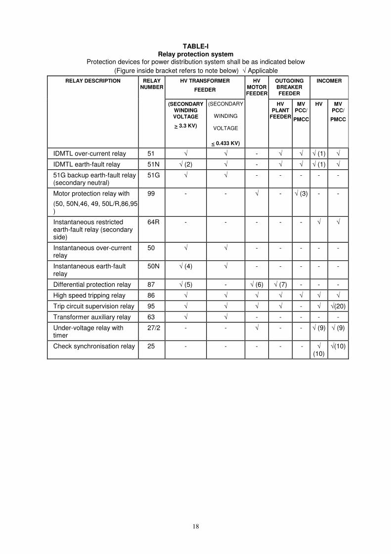
vii) Recommended relay protections
for Transformers, motors and feeders which are generally encountered in distributing network are given below :
18
TABLE-I Relay protection system
Protection devices for power distribution system shall be as indicated below
(Figure inside bracket refers to note below) √ Applicable
RELAY DESCRIPTION RELAY NUMBER
HV TRANSFORMER
FEEDER
OUTGOING BREAKER FEEDER
INCOMER
(SECONDARY WINDING VOLTAGE
> 3.3 KV)
(SECONDARY
WINDING
VOLTAGE
< 0.433 KV)
HV MOTOR FEEDER
HV PLANT
FEEDER
MV PCC/
PMCC
HV MV PCC/
PMCC
IDMTL over-current relay 51 √ √ - √ √ √ (1) √
IDMTL earth-fault relay 51N √ (2) √ - √ √ √ (1) √
51G backup earth-fault relay (secondary neutral)
51G √ √ - - - - -
Motor protection relay with
(50, 50N,46, 49, 50L/R,86,95 )
99 - - √ - √ (3) - -
Instantaneous restricted earth-fault relay (secondary side)
64R - - - - - √ √
Instantaneous over-current relay
50 √ √ - - - - -
Instantaneous earth-fault relay
50N √ (4) √ - - - - -
Differential protection relay 87 √ (5) - √ (6) √ (7) - - -
High speed tripping relay 86 √ √ √ √ √ √ √
Trip circuit supervision relay 95 √ √ √ √ - √ √(20)
Transformer auxiliary relay 63 √ √ - - - - -
Under-voltage relay with timer
27/2 - - √ - - √ (9) √ (9)
Check synchronisation relay 25 - - - - - √ (10)
√(10)
19
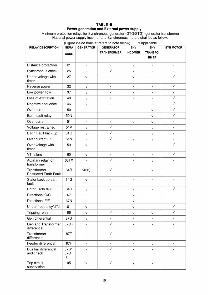
TABLE -II Power generation and External power supply
Minimum protection relays for Synchronous generator (GTG/STG), generator transformer National power supply incomer and Synchronous motors shall be as follows
(Figure inside bracket refers to note below) √ Applicable
RELAY DESCRIPTION NEMA
CODE
GENERATOR GENERATOR
TRANSFORMER
EHV
INCOMER
EHV
TRANSFO-
RMER
SYN MOTOR
Distance protection 21 - - √ - -
Synchronous check 25 - √ √ - -
Under voltage with timer
27 √ - √ - √
Reverse power 32 √ - - - √
Low power flow 37 √ - - - -
Loss of excitation 40 √ - - - √
Negative sequence 46 √ - - - √
Over current 50 - - - √ √
Earth fault relay 50N - - - √ √
Over current 51 - - √ √ -
Voltage restrained 51V √ √ √ -
Earth Fault back up 51G √ √ √ -
Over current E/F 51N - √ √ √ -
Over voltage with timer
59 √ - - - √
VT failure 60 √ - - - √
Auxiliary relay for transformer
63TX - √ - √ -
Transformer Restricted Earth Fault
64R √(26) √ - √ -
Stator back up earth fault
64G √ - - - -
Rotor Earth fault 64R √ - - - √
Directional O/C 67 - - √ - -
Directional E/F 67N - - √ - -
Under frequency/df/dt 81 √ - √ - √
Tripping relay 86 √ √ √ √ √
Gen differential 87G √ - - - -
Gen and Transformer differential
87GT - √ - - -
Transformer différentiel
87T - √ - - -
Feeder differential 87F - - - √ -
Bus bar differential and check
87B/87CH
- √ - - -
Trip circuit supervision
95 √ √ √ √ -

20
RELAY DESCRIPTION NEMA
CODE
GENERATOR GENERATOR
TRANSFORMER
EHV
INCOMER
EHV
TRANSFO-
RMER
SYN MOTOR
Dead bus charging relay
98 √ - - - -
Over fluxing 99 √ - - - -
Notes:
1. In case of HV switchboards with continuous parallel operation of incomers, following additional relays shall be provided:
a. One set of 87B (Bus differential) and 95 B (Bus wire supervision) for each bus section.
b. 67 and 67N (Directional IDMTL over current and earth fault) relays for the incomers.
2. Instantaneous earth fault (50N) shall be provided only for transformer with delta primary.
3. For breaker fed motor feeders. Relay 50 shall not be provided for contactor controlled feeders.
4. Directional IDMTL earth fault (67N) shall be provided for transformer with star primary.
5. For transformers rated 5 MVA and above.
6. For motors rated 1500 kW and above.
7. For critical/long feeders and plant feeders connected to main power generation and distribution bus. A plant feeder implies outgoing feeders from one switchboard to another switchboard of same voltage level.
8. Intentionally left blank.
9. Wherever auto-transfer feature is provided
10. For switchgears where continuous or momentary paralleling of Incomers is envisaged, check synchronising relay shall be provided
11. 51G and 64R relays shall not be provided for input transformer of VFD system.
12. The bus tie feeders in HV switchboards shall be provided with 51, 51N, 86 and 95 relays.
13. HV capacitor bank feeders shall be provided with 51, 51N, 59 (over voltage), 60 (Neutral displacement), 86 and 95 relays.
14. The following feeders shall be provided with timers for delayed tripping on bus under voltage while the under voltage relay shall be common for the bus
a. HV and MV capacitor feeders
b. HV and MV breaker controlled motor feeders
c. Contactor controlled motor feeders with DC control supply.
Numerical relays where ever provided for motor and capacitor feeders shall use in built under voltage relay and timer for delayed tripping on bus under voltage.
15. One no. DC supply supervision relay (80) shall be provided for each incoming DC supply to the switchboard.
16. One set of bus differential relays (87B) and bus wire supervision relay (95 B) for each bus section shall be provided for HV switchboards connected directly to generation buses
17. In case of numerical relays, all relays shall be comprehensive units including protection and metering.
18. Wherever numerical relays are used, under voltage and over voltage functions along with associated timer shall be part of the numerical relays.
19. Wherever numerical relays are used, Auto changeover logic between Incomers and bus coupler(s) shall be built in the numerical relay.
20. Wherever numerical relays are used, Tripping relays (86) & Trip Circuit supervision relay (95) shall be part of the numerical relay.
21. 2Nos of 86 relays shall be considered for HV and MV breaker fed motors, for ease of differentiating between Process and Electrical trips.

21
22. Breaker control switch shall be hardwired type.
23. Stand by earth fault relay 51G shall be provided in the incomer of switchboard fed from transformers and transformer and switchboard located remotely from HV substation.
24. Restricted earth fault relay 64R shall be provided in the incomer of switchboard fed from transformers having secondary voltage greater than 3.3KV and secondary winding is star connected.
25. Relay 51V voltage controlled over current relay shall be provided on specific requirement considering the rating of the outgoing feeders with respect to the Incomer rating. Generally this relay shall be provided wherever CT primary current of outgoing feeders is exceeding 40% of the CT primary current of the Incomer.
26. 415V DG set rated above 500kVA shall be additionally provided with Restricted Earth Fault protection, 64R.

22
viii) Medium Voltage Motor Protection:
- The minimum protection
requirement shall include fuses and thermal overload relay suitably co-ordinated with contactor characteristics as per applicable Indian Standards (BIS). However MV Motors controlled by circuit breakers should have either releases or relays for Motor Protection.
- Large rating motors which
are contactor fed (55 KW and Above) should have core balance earth fault protection in addition to bimetal and fuse coordination or composite motor protection relay.
- Bimetal relays shall be
preferably with inherent protection against single phasing.
4.6 Emergency Power Supply
i) This is an independent back-up source of electric energy that upon failure or outage of normal source, automatically provides reliable electric power within specified time to critical devices and equipment whose failure to operate satisfactorily may jeopardise the health and safety of personnel or result in damage to property.
ii) The emergency power supply system shall feed the following loads to enable continuity of supply in the event of failure of MAIN SUPPLY.
- Electrical loads essential for the
safe shutdown of the plant. - Emergency lighting, security
lighting, obstruction lights. - Process plant instruments as
required - Communication equipment, Fire
Alarm control panels. - D.C. Supply system, UPS system
- Auxiliaries of emergency set as applicable
- Fire fighting equipment excluding
main fire water pumps - Essential ventilation loads, and - Loads critical for process, plant and
personnel safety.
iii) Emergency power supply shall be available as per process/equipment requirements, but within a period not exceeding 30 seconds from the instant of failure of normal supply. Emergency Power shall be supplied from suitably rated diesel generator set conforming to CPCB/ MOEF guidelines.
iv) Unless otherwise required, the
emergency generator in general should not run continuously in parallel with the normal power supply system. However, to facilitate periodic testing and maintenance it is preferable to include synchronising facilities for short time parallel operation of D.G. set unless objected to by electrical supply authorities.
v) Upon restoration of normal power
supply, it is preferable to synchronize the DG supply with the normal supply and only then switch-off the DG set. This will avoid unnecessary tripping of the emergency loads upon restoration of normal power supply.
4.7 Critical Power Supply Systems
i) These systems shall have inherent independent battery backup to maintain continuity of supply to critical loads (e.g. process control, communication, fire alarm systems etc.) in the event of normal/emergency supply failure.
4.7.1 Un-interrupted Power Supply
(UPS)
i) An un-interrupted power supply shall be provided, as required for meeting critical loads that cannot withstand a momentary interruption/other A.C. mains disturbance in supply voltage. A separate battery shall be provided for UPS system.

23
ii) UPS supply should be provided for
control circuit of all the critical variable speed drives.
iii) It is desirable that a 2 x 50% battery bank configuration be provided.
iv) Following loads shall be connected to
the UPS system: - Critical instrumentation and process
control,
- Critical communication equipment,
- Microprocessor based Digital Control System.
Incoming power to the UPS system shall be fed from the emergency system, wherever provided.
v) In case of total power failure, un-interrupted power supply shall be available for at least 30 minutes or as determined by the process considerations.
vi) Each branch circuit of the UPS
distribution system shall have a fused disconnect switch. The fuse shall be fast clearing type and the fuse rating shall be coordinated with the rating of the UPS system.
4.7.2 DC Power Supply
i) Unless otherwise specified, independent DC power supply systems shall be provided for the following:
- Plant shut-down system and DC
instrumentation. - Electrical switchgear controls and
critical (escape) lighting, critical D.C. drives viz. Lube Oil pumps etc.
ii) Each DC power supply system shall include charger-cum-rectifier, battery and DC distribution board. DC link in the UPS system shall generally not be tapped for DC instrumentation power supply except in rare circumstances.
iii) It is desirable that a 2 x 50% battery
bank configuration be provided.
iv) Fire alarm system shall have a dedicated DC battery backup system.
v) DC supply for electrical controls,
instrumentation, UPS etc. shall have separate independent battery banks. The DC bus for electrical controls and DC lighting should preferably be distinct to avoid switchgear control supply being affected by faults in DC lighting circuits.
4.7.3 Battery Sizing for DC systems
i) Electrical Switchgear and Controls
Battery shall normally be sized for a load cycle having a minimum duration of one hour. While deciding the load cycle, consideration shall be given to the specific operating/safety requirements of plant & equipment e.g. lube oil pump of STG for bearing oil flushing. The duration for battery sizing hence shall vary accordingly as per specific operational requirements.
ii) DC Instrumentation Shutdown System This shall in general be sized for 30
minutes, unless otherwise required. iii) Fire Alarm System The battery shall be sized for the
duration and load in line with the guidelines given in IS 2189.
iv) EPABX (Telephone System) This will have an independent battery back
up system.
4.7.4 Annunciation
For plant DC systems Sensitive earth fault detectors along with Earth leakage current ammeter having centre zero shall be provided in DC system to annunciate earth faults.
5.0 Electrical Equipment for Classified
Areas
i) All the areas within the Battery limits shall be classified for degree and extent of hazard from flammable materials. The basis for hazardous area classification recognises the differing degrees of probability with which flammable atmosphere may arise in the installation, in terms of the frequency of occurrence and the probable duration of existence on each occasion.

24
ii) Following factors shall be considered for proper selection of electrical apparatus and equipment for areas where flammable gas or vapour risks may arise:
a) Area classification, i.e. Zone 0,
1 or 2
b) Gas group classification, i.e. gas groups IIA, IIB or IIC.
c) Temperature classification i.e.
T-Rating.
d) Environmental conditions in which apparatus is to be installed.
Wherever practicable, electrical
apparatus in general and switch and control apparatus in particular shall be installed in safe area. Substation and control room shall be located in safe area. While deciding the route of overhead power lines, necessary considerations shall be given to avoid overhead lines passing through hazardous areas.
Electrical equipment intended for service
in hazardous area shall be selected in accordance with IS : 5571 and these shall be certified by recognised testing/ certifying authorities of country of origin (e.g. CIMFR, LCIE, UL, FM, PTB, Baseefa etc.) and approving authorities i.e. CCE or DGMS or DGFASLI as applicable.
For details on hazardous area
classification, enclosure protection etc. OISD standard 113, National Electric Code IS 5571, 5572, IS 13408 Petroleum Rules and Oil Mines Regulations shall be referred.
iii) General guidelines for type of protection
for electrical equipment in hazardous areas are enumerated in Table-III.
TABLE-III TYPES OF PROTECTION
Area Classification
Description
Symbol
Intrinsic safety category ‘ia’
‘ia’
Encapsulation ‘ma’
Zone 0
Other electrical apparatus, specifically
designed for Zone 0. (See
Note 1)
‘s’
Any type of protection
adequate for Zone 0.
Intrinsic safety category ‘ib’
‘ib’
Flame proof enclosure
(See Note 6)
‘d’
Intrinsic safety category ‘ib’
‘ib’
Pressurisation (See Table IV)
‘p’, ‘px, py’
Sand filling ‘q’ Encapsulation ‘m’, ‘ma’,
‘mb’
Zone 1
Other electrical apparatus specifically
designed for Zone 1
‘s’
Any type of protection
adequate for Zone 0 or Zone
1
Intrinsic safety category ‘ic’
‘ic’
Increased safety (See
Note 2)
‘e’
Non-sparking apparatus
(See Note 2)
‘n’
Pressurisation (See table IV)
‘pz’
Encapsulation ‘m’, ‘ma’, ‘mb’
Zone 2
Oil Immersion (see note 4)
‘o’
Note 1 It may be noted that as per petroleum
rules the use of intrinsically safe electricity apparatus in zone ‘0’ area is
25
permitted only when the use of such apparatus cannot be completely excluded, whereas the Oil Mines regulations prohibit use of any electrical equipment in zone ‘0’ areas.
Note 2 The apparatus with type of protection
‘e’ and type of protection ‘n’ when installed outdoors shall have enclosures having the ingress protection as recommended in IS 469/2147.
a. IP 55 where there are uninsulated
conducting parts internally, and b. IP 44 for insulated parts. Note 3 Name plate details of equipment
intended for use in hazardous area shall include relevant marking of hazardous protection as per applicable codes.
Note 4 Oil-immersed apparatus may be used
only in case its security will not be impaired by tilting or vibration of the apparatus.
Note 5 Flameproof enclosures are covered
under compulsory certification. Note 6 : In Zone ‘1’ areas, Ex d/e equipment
i.e. Ex ‘d’ equipment with Ex ‘e’ terminal boxes is also permissible.
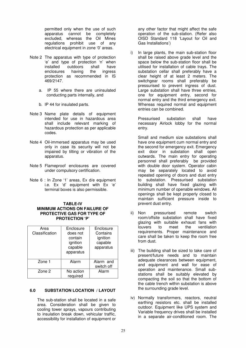
TABLE-IV MINIMUM ACTIONS ON FAILURE OF
PROTECTIVE GAS FOR TYPE OF PROTECTION ‘P’
Area
Classification Enclosure does not contain ignition capable
apparatus
Enclosure Contains ignition capable
apparatus
Zone 1 Alarm Alarm and switch off
Zone 2 No action required
Alarm
6.0 SUBSTATION LOCATION / LAYOUT
The sub-station shall be located in a safe area. Consideration shall be given to cooling tower sprays, vapours contributing to insulation break down, vehicular traffic, accessibility for installation of equipment or
any other factor that might affect the safe operation of the sub-station. (Refer also OISD Standard 118 ‘Layout for Oil and Gas Installations’)
i) In large plants, the main sub-station floor
shall be raised above grade level and the space below the sub-station floor shall be utilised for installation of cable trays. The substation cellar shall preferably have a clear height of at least 2 meters. The switchgear rooms shall preferably be pressurised to prevent ingress of dust. Large substation shall have three entries, one for equipment entry, second for normal entry and the third emergency exit. Whereas required normal and equipment entries can be combined.
Pressurised substation shall have
necessary Airlock lobby for the normal entry.
Small and medium size substations shall
have one equipment cum normal entry and the second for emergency exit. Emergency exit door in substation shall open outwards. The main entry for operating personnel shall preferably be provided with double door system. Operator cabin may be separately located to avoid repeated opening of doors and dust entry to substation. Pressurised substation building shall have fixed glazing with minimum number of openable windows. All openings shall be kept properly closed to maintain sufficient pressure inside to prevent dust entry.
ii) Non pressurised remote switch
room/offsite substation shall have fixed glazing with suitable exhaust fans with louvers to meet the ventilation requirements. Proper maintenance and care shall be taken to keep the room free from dust.
iii) The building shall be sized to take care of
present/future needs and to maintain adequate clearances between equipment, and equipment and wall for ease of operation and maintenance. Small sub-stations shall be suitably elevated by compacting the soil so that the bottom of the cable trench within substation is above the surrounding grade level.
iv) Normally transformers, reactors, neutral
earthing resistors etc. shall be installed outdoor. Equipment like UPS system and Variable frequency drives shall be installed in a separate air-conditioned room. The

26
battery banks shall be located in a separate, freely ventilated room in the substation building along with the necessary fresh air inlet and exhaust system and water connection. Battery room door shall be provided with louvers at the bottom to aid cross-ventilation. Floor of the battery room and the walls up to height of one metre shall have acid resisting material/coating/be painted with acid/alkali resistive paint or otherwise protected.
v) Necessary space to keep equipment under
repair such as breakers, switch control gear items, spares/consumables like fuses etc. shall also be identified in building layout.
vi) It is recommended to locate DG sets in a
separate house/shed away from Substation in a safe area to reduce noise level in substation. If required DG set of smaller rating can be located in substation building provided the substation is located in a safe area. However in such cases, the foundation of such D.G. sets shall be structurally delinked from the slab or floor of the rest of the substation building. Exhaust of Diesel Engine shall be kept away from Process/Hydrocarbon area.
vii) Transformer yard/bay shall be provided
with fencing and gate and shall have fire isolation walls for individual transformers. Oil immersed equipment involving use of large quantity of oil shall have oil soak pit and drain arrangement as per Indian Electricity Rules and regulations. Fire fighting equipment, first-aid boxes, etc. shall also be provided as required. (Further guidelines on this can be had from OISD standard 116 - ‘Fire Protection facilities for Petroleum Refineries and Oil/Gas Processing Plants’ and OISD standard 117 ‘Fire Protection Facilities for Petroleum Depots and Terminals.)
viii) The substation equipment layout and the
clearances between different equipment shall be planned to ensure ease of operation and maintenance and meet all requirements from the point of view of safety of the operating personnel.
ix) Clearance between various equipments
shall also satisfy respective equipment manufacturer’s requirements and Indian Electricity Rules. Where these are not specified the following minimum clearances are recommended as general guidelines.
Description Distance a) At the rear of HV
Switchboard
1500mm
b) At the front HV Switchboard
2000mm
c) At the side of various Switch boards and from wall
1000mm
d) At the front of various Switchboards
1500mm
e) Between front to front of two Switchboards.
(Say DRAWOUT MCCS) facing each other.
2000 mm
f) At the rear of MV Switchboards requiring rear access
1000mm
g) Rear clearance in other cases
More than 750mm otherwise less than 200mm.
h) Transformers with wall on one side
As per IS 10028
i) Transformers with walls on three sides
As per IS 10028
j) Clear height of bus-duct from finished floor level
2000mm
k) Clear space between Switchboard top and beam soffit
1000mm
Note: The maximum length of switchgear line-
up may preferably be limited to 15-20 metres considering operation and maintenance requirements.
x) It is recommended that battery room, UPS room, process shut-down DC system room, operator’s room of large sub stations, located close to process units should have blast resistant walls. This is to protect vital control power sources from any external damage, thus ensuring availability of control power for safe shutdown in disastrous conditions suitable for indoor use.

27
7.0 ELECTRICAL EQUIPMENT Electrical equipment shall be selected,
sized and installed so as to ensure adequacy of performance, safety and reliability. The equipment in general shall conform to relevant Indian Standards and shall be suitable for installation and satisfactory operation in the service conditions envisaged. Specific attention is drawn to IS:9676 for deciding the design ambient temperature of electrical equipment.
7.1 CHARACTERISTICS Every item of electrical equipment
selected shall have suitable characteristics appropriate to the values and conditions on which the design of the electrical installation is based and shall in particular, fulfil the requirements given in Clause i) to vii) below.
i) Voltage
Electrical equipment shall be suitable with
respect to the maximum steady voltage (rms value for AC) likely to be applied, as well as over voltages likely to occur.
Note: For certain equipment, it may be
necessary to take account of the lowest voltage likely to occur.
Considerations shall also be given to the
protective measures inherent in the systems and the method of neutral earthing viz. earthed or unearthed system.
ii) Current
All electrical equipment shall be selected
with respect to the maximum steady state current (rms value for AC) which it has to carry in normal service, and with respect to the currents (prospective, short circuit currents) likely to be carried under abnormal conditions and the period (for example, operating time of protective devices, if any) during which it may be expected to flow.
iii) Frequency
Electrical equipment shall be suitable for
continuous operation with respect to the system rated frequency with variation limits likely to occur.
iv) Power All electrical equipment to be selected on
the basis of their power characteristics shall be suitable for the duty demanded from the equipment, taking into account the load factor and the service conditions. Each equipment shall be able to deliver its rated power for specified supply and site conditions with temperature rise remaining well within the design limits as per applicable IS codes.
v) System earthing All electrical equipment shall be selected
considering the system neutral earthing particularly in high voltage systems where resistance earthing is commonly employed.
vi) Conditions of Installation
a) All the electrical equipment selected
shall have proper protection against corrosive and solvent agents, water ingress, thermal and mechanical stresses as determined by the environmental factors. If, however, an item of equipment does not have by design, the properties corresponding to its location, it should be used on condition that adequate additional protection is provided as part of the completed electrical installation. In addition to the above, noise level and cooling/ventilation shall also be considered. PAINTING
a) Rotating Machinery Internal and external parts of the
casing and all metal parts likely to come in contact with the surrounding air should be protected with epoxy paint that will resist corrosion under the particular atmospheric conditions.
b) Switchgear panels and
service boards Painting of the switch gear panels
should be as per manufacturer’s standard.
All unpainted steel parts should be zinc passivated or suitably treated to prevent corrosion. If these parts are moving elements, then these should be greased.
28
c) Outdoor electrical equipment Painting of the outdoor equipment
should be as per manufacturer’s standard. All metal parts likely to come in contact with the surrounding air should be protected with epoxy paint that will resist corrosion under the particular atmospheric conditions.
vii) Prevention of Harmful effects a) All electrical equipment shall be
selected so that it will not cause harmful effects on other equipment or impair the supply during normal service including switchgear operations. In this context, the factors which may have an influence include:
* Power factor * Inrush current * Asymmetrical load * Harmonics * Transient voltage
dips/overshoots. b) Energised parts shall be sufficiently
enclosed or isolated so as not to expose personnel to explosion, fire, arcing, or shock hazards. Adequate safety features shall be incorporated in equipment design for the safety of operating personnel.
7.2 EQUIPMENT FEATURES Certain essential safety features in
design to be considered in specifying and sizing of commonly encountered equipment such as Transformer, Switchgear, Motors, Cables, Battery charger, Battery, and UPS etc. are enumerated below.
7.2.1 Transformers
i) The kVA rating shall depend upon the maximum simultaneous continuous load and probable system expansion loads. In general, the rating and the percentage impedance of each transformer shall be selected to limit the continuous current rating and short circuit current to values within the ratings of available switchgear. The transformer impedances shall
generally be as per Indian standards unless otherwise required. The rating and the percentage impedance of transformer shall be compatible to permit start of highest rated motor while the transformer is preloaded with maximum operating base load.
ii) Transformers connected to Grid
supply / Generator transformer may have ON LOAD TAP CHANGERS for in-plant control of secondary voltage. Plant distribution transformers may have OFF CIRCUIT TAP changers.
iii) In addition to standard accessories,
the transformer shall be provided with auxiliary devices/ protective devices such as Buchholz relay, oil level and oil temperature indicator with alarm/ trip output contacts and current transformers for the secondary side neutral for Protection. Transformers of rating above 2000 kVA should have winding temperature indicators with Alarm/ Trip provisions.
7.2.2 High Voltage (HV)/ Medium Voltage
(MV) Switchboards
i) These shall be designed to ensure maximum safety during operation, inspection, connection of cables and maintenance with Switchboards energised.
ii) The switchboard shall be totally
enclosed, dust and vermin proof.
iii) Each unit of the switchgear shall have necessary internal sheet metal barrier to form separate compartments for buses instruments/ relays/ cable connections etc. Compartment for cable connection shall allow cable pulling, termination and connection work with switchgear energised. Suitable arc propagation barriers shall also be provided. Independent pressure release flaps shall preferably be provided for each different compartment of HV Switchboards. Terminal strip for outgoing control cable connections should be accessible to facilitate working and testing with breaker in test/service condition and while the switchboard is energised.
iv) Barriers shall be provided to permit
personnel to work safely within an empty compartment with the bus bars

29
energised. The minimum clearances between live parts and between live parts to earth and neutral and creepage distance of bus bars shall conform to IS 4237.
v) The drawout carriage on the switchboard shall have three positions viz., ‘Service’, ‘Test’ and ‘drawn out’. Automatic safety shutters shall be provided to ensure the inaccessibility of all live parts after the breaker is drawn out. It shall not be possible to drawout the carriage or rack it in with circuit breaker closed. The breaker/ contactor feeder trolley shall remain inside the cubicle even in the test position. There shall be distinct overall door for the breaker compartment and it should be lockable. All circuit breaker truck/trolley of the same rating shall be interchangeable.
vi) Suitable interlocks shall be provided to prevent faulty operation such as:
- ‘Plugging in’ or ‘drawing out’ of a closed breaker.
- ‘Plugging in’ a breaker with earthing isolator closed.
- ‘Closing’ of earthing isolator with the
breaker ‘Plugged in’. - Pulling out of auxiliary circuit plug with
breaker in service position. - Pushing in breaker to service position
with auxiliary circuit plug not in position.
- Opening of compartment door with isolating switch in ON position and vice-versa for Motor Control Centres.
The maximum height of operating
handle/switches shall not exceed 1900 mm and the minimum height not below 300 mm.
- It shall not be possible to operate the circuit-breaker unless it is fully in service or Test or isolated position.
vii) Suitable eye bolts for lifting of panels shall be provided. On removing the eye bolts, no holes offering access to panel shall be permitted.
viii) Busbars and supports shall withstand specified short circuit level without permanent deformation. Busbars shall
be preferably sleeved and joints shall be taped/shrouded. Minimum clearances between live parts, between live parts to Earth and Neutral shall conform to applicable IS code (IS 4237) Switchboards shall have additional safety features such as falling tool shrouds for trapping of free fall of maintenance tools on live parts. Busbar supports shall be of synthetic material with high tracking index. The switchboard shall have earth busbar of adequate size. The switchgear drawout trolley (in case of drawout design) shall have suitable scraping earth connection. Feeder tag plates shall be provided at both front and rear side of panels. Where required, busbar routing shall be clearly marked on the back side of the H.V. Switch board panels for easy identification during maintenance.
ix) All non-current carrying metallic parts of
mounted equipment/components shall be bonded to the earth bus.
x) Surge absorbers to limit the switching surges shall be provided as dictated by the type of arc quenching media and switching device.
xi) Starting of motors from substation shall not be allowed and switch boards shall not have close push button at switchboard for motor starting.
xii) In specific cases, motors requiring frequent start/stop, (e.g. product, loading pumps etc.) shall be controlled by contactor feeder appropriate to its rating.
xiii) Switch Boards shall have anti condensation heaters.
xiv) All HV switch gears should have provision of view glasses to take thermo graphic readings for predictive/ preventive maintenance. It must be ensured that all such switch gears with view glasses windows have been duly type tested and certified for internal arc faults as per the provisions envisaged in IEC:62271 or other equivalent international standards.
7.2.3 MOTORS HIGH VOLTAGE (HV) & MEDIUM VOLTAGE (MV)
7.2.3.1 General
i) Motors shall be totally enclosed, fan cooled type as far as practicable. As a minimum, all HV motors shall have anti condensation heaters. The

30
minimum degree of enclosure protection for motor shall preferably be IP 44 for indoor use and IP 55 for outdoor duty motors.
ii) Generally Motors upto and including
160 kW shall be rated for medium voltage and motors of rating above 160 kW shall be rated for high voltage. If required, the rating of medium voltage motors may be extended up to and including 200 kW. Sleeve or anti friction type bearings shall be used. Vertical motors shall have thrust bearings suitable for the load imposed by the driven machinery. Unless otherwise specified, all motors shall be designed for ‘Direct ON line’ starting.
iii) High voltage DOL starting motors shall
be suitable for starting under specified load conditions with 80% of the rated voltage at the terminals and medium voltage DOL starting motors shall be suitable for starting under specified load conditions with 75% of the rated voltage at the terminals.
iv) The permissible noise level shall not
exceed the stipulations laid down in IEC 60034-9.
v) Motor vibrations shall be within the
limits of IS-4729 unless otherwise specified for the driven equipment. Motors with sleeve bearings may require proximity probes to measure shaft vibration adjacent & relative to the bearings.
vi) Motors shall be required for
continuous, satisfactory operation at rated output under the following conditions :
a) The terminal voltage
differing from its rated value by not more than ± 6%.
b) The frequency differing from
its rated value by not more than ± 3%
c) Any combination of (a) and
(b).
vii) Motor ratings and torque characteristics shall be adequate to accelerate the load from zero to rated speed under starting requirements as stipulated by process operating conditions. Normally, the starting time
shall be less than the hot withstand time of the motor.
viii) MV Motors in general and HV Motors
where required shall be suitable for restarting under full load after a momentary loss of voltage with the possibility of application of 100 percent of the rated voltage, when the residual voltage has dropped down to 50 percent and is in phase opposition to the applied voltage.
ix) Medium voltage motors above 55 kW
rating and not requiring frequent starts; should be provided with suitable type of circuit breakers and composite motor protection relays.
x) Motor bearings shall be selected to
give a minimum L-10 life rating of 5 years (40,000 hours) at rated operating condition (the L-10 rating life is the number of hours at constant speed that 90% of a group of identical bearings will complete or exceed before the first evidence of failure). The bearings shall be adequate to absorb axial thrust in either direction produced by the motor itself or due to shaft expansion. On line greasing facility should be provided on motor for all grease lubricated bearings (anti friction bearings). Wherever space heaters are provided for motors, a separate terminal box should be provided for termination of space heater cables, as far as practicable.
xi) Considerations should be made at the
design stage for the torque values of all the Pumps / Fans requiring auto re-acceleration with discharge valve open.
7.2.3.2 H V Motors
i) Winding insulation shall be class F and temperature rise limited to that specified in the applicable IS for class B insulation.
ii) Motors shall be designed to allow
minimum number of consecutive hot starts as dictated by process operating requirements. Number of uniformly spaced start-ups in an hour shall be a minimum of three.
iii) The main power Terminal Box shall be
phase segregated and suitable to

31
withstand the specified fault level for a minimum duration of 0.2 sec. (Commensurate with instantaneous short circuit protection). Winding ends shall be preferably brought out and star point made in a separate terminal box. Neutral terminal box shall have necessary space provision to mount differential CTs for motors of rating 1500 kW & above.
iv) Motors of rating above 1000 kW shall
be provided with RTDs, BTDs and scanners. Separate terminal boxes shall be provided for space heater and RTDs, BTDs.
v) Induced voltage at the shaft of the motor having uninsulated bearing system shall not exceed 250 mV r.m.s. for roller and ball bearings and 400 mV r.m.s. for sleeve bearings with the motor running at no load. Alternatively, the non driving end bearing shall be insulated from the motor frame to avoid circulating current.
vi) The insulated bearing end shield or
pedestal shall bear a prominent warning and manufacturer shall provide detailed drawing showing insulation arrangement.
vii) Motors shall be designed to withstand
impulse voltage of at least (4Un+5) kV with a wave front raise rise time of 1.2 microsecond and decay time of 50 microsecond to half the peak voltage.
viii) The inter-turn insulation of HV motors
shall be able to withstand a peak voltage of at least 0.5 (4Un+5) kV with a wave front rise time between 0.5 & 1.5 µs and a decay time to half the peak voltage of between 3 & 10 µs.
Un = rated line to line voltage. ix) Polarisation index
Polarisation index of HV stator winding shall have a value of at least 2. If the insulation value of the motor exceeds a value of 120 (Un+1) (where Un is rated line - line voltage (kV) MΩ, a minimum polarisation index of 1.5 is acceptable.
7.2.3.3 M V Motors
i) Motors shall be designed to allow three consecutive starts from cold condition, two consecutive starts from
hot condition and four uniformly distributed starts in one hour.
ii) Winding insulation shall be class F and
temperature rise limited to that specified in the applicable IS for class B insulation. The windings shall be tropicalised and adequately braced. The ends of the windings shall be brought out in a terminal box with six terminals with suitable links to connect them in Delta. However, motors rated up to 2.2 kW may be connected in star with three terminals.
iii) The terminal box of motor controlled
by air circuit breaker shall be capable of withstanding the full internal short circuit conditions, with the specified system fault level for a minimum duration of 0.2 second (Commensurate with instantaneous short circuit protection). Where motor control is through contactor and MCCB, or back up fuse, the terminal box shall be able to withstand the let-through energy of protective devices corresponding to maximum system fault level.
iv) The terminal box shall be of sturdy
construction and large enough to facilitate easy connection of required number of cable runs and size. (Specifically Aluminium Conductor Cables). Additional trifurcating boxes may be considered for motors requiring termination of two or more parallel runs of power cables.
7.2.4 Battery Charger and DC
Distribution Board
Charger and distribution board shall be floor mounted, free standing, metal enclosed and vermin proof type having front access hinged door and suitable for indoor use.
This shall consist of battery charger/rectifier, which shall feed the load and keep the batteries under fully charged condition. Provision shall also be made for necessary boost charging/ initial charging of battery.
7.2.5 Batteries and Battery Accessories
i) Batteries shall be indoor stationary type with adequate capacity to meet the backup requirements as envisaged

32
in the duty cycle. Accessories shall generally be as follows:
- Battery stand made of solid polymer or epoxy/ powder coated mild steel (MS).
- Inter-cell, inter row and inter bank
connectors and end take offs. - Porcelain cell insulators, stand
insulators. (As applicable) - Hydrometers suitable for specific
gravity readings. (As applicable) - Cell number plates as required. - Thermometer with specific gravity
correction scale. (As applicable) - Cell testing voltmeter (3V-0-3V)
complete with 1 m long leads. - Rubber gloves - Rubber aprons - Spanner Set.
ii) While sizing the battery following factors shall be taken into consideration, in addition to envisaged duty cycle:
- Temperature correction factor. - Ageing factor as applicable. 7.2.6 Equipment for Uninterrupted
Power Supply System
i) This shall be of free-standing, floor mounted, metal enclosed and vermin proof type having hinged door for front access and suitable for indoor use.
ii) Under normal conditions, the rectifier-
cum-charger shall feed the inverter and charge the battery set. In case of mains failure, the battery shall supply the necessary power to the inverter. The inverter in turn feeds the load through the static switch. If the inverter malfunctions or is overloaded, the load shall be instantaneously transferred to the by-pass line through the static switch. Normally the inverter shall be operated in synchronised mode with the by-pass line, and manual forward transfer or manual reverse transfer shall be effected without any break.
Automatic forward transfer, in case of inverter malfunction, shall be effected with a break not exceeding 5 ms.
7.2.7 Capacitor Banks
i) The capacitor shall conform to IS 2834 - specifications for shunt capacitor for power system.
ii) H V capacitor shall comprise
appropriate numbers of basic single phase units (minimum 4Nos. basic units in parallel per phase) which shall be connected in star formation.
iii) Capacitor banks shall be with necessary
discharge resistors to reduce the terminal voltage of each unit to a value equal to or less than 50V in 5 minutes.
iv) Steel rack assembly suitable for outdoor
installations (where outdoor location is required) to accommodate the basic capacitor units with necessary post insulators. Panel assembly (where indoor location is required) to accommodate the basic capacitor units, interconnecting busbars, insulators etc. The panel shall have minimum IP-51 protection and shall be constructed with sheet steel of minimum thickness 2.0 mm.
v) Necessary series reactor to limit inrush
current and suppress harmonics (where required)
vi) The impregnant in the capacitors shall
be non-toxic.
7.2.8 Emergency Generator
i) The emergency generating sets shall
form a complete package and shall be designed to start automatically on power failure and feed the selected loads. It shall be capable of taking care of the load variations (e.g. the starting of largest rated motors on a preloaded system). The unit shall be complete with necessary starting equipment, associated control panel and shall be suitable for remote starting.
ii) The regulation of generator voltage shall be automatic and necessary instruments for metering viz. Ammeter, Voltmeter, Frequency meter, kWh meter, pf meter, Hour run counter etc. shall be included in the control panel.

33
iii) Warning of abnormal conditions shall be incorporated prior to automatic trip to prevent unnecessary shutdown.
iv) All the six stator winding ends shall be brought out to an externally mounted terminal box and shall be connected in star. Necessary temperature detectors shall be provided for the stator winding. The terminal box shall have sufficient space to receive the cables of specified size.
v) Emergency DG set shall have Auto starting arrangement but only with manual switching off features. The rating (Ampere Hours) of battery, for cranking the engine shall be adequate to make three attempts with an interval of 5 to 10 seconds, if required. In case the engine fails to start ‘FAIL TO START’ annunciation shall be provided in substation or in control room.
vi) The generator set shall be provided with complete protection against overloads, short circuits, ground faults, excitation failure, prime-mover failure and shall include other connected instrumentation interlocks.
vii) The load shall be switched on to the
generator only after the requisite voltage build-up.
viii) Diesel Engine installation, does not call for Area Classification, provided the DG room is properly ventilated. Normally the ventilation provided to remove heat from the radiator is adequate to take care of the hazard aspect. DG sets shall comply with the latest guidelines of environment ministry with regard to noise levels.
7.2.9 Cables
i) In order to avoid spread of fire due to cables, it is recommended that the outer PVC sheath of all cables used in industry shall be flame retardant type conforming to category AF as per IS: 10810. The cables shall have a low smoke property. The minimum Oxygen Index shall be 29
Note 3.
ii) High voltage cables may be
Aluminium/Copper Conductor XLPE insulated PVC sheathed, armoured type.
iii) The conductor screen, XLPE insulation screen shall all be extruded in one operation by ‘Triple Extrusion’ process.
iv) 1.1 kV grade cables may be Aluminium/Copper Conductor PVC/ XLPE insulated, PVC sheathed, armoured type.
v) All power and control cables shall preferably have extruded inner and outer sheaths.
vi) Where single core cables are armoured and are meant for use on AC circuits, armouring with non-magnetic material (e.g. Aluminium) shall be employed.
The communication cables shall conform to DOT (Department of Telecom) specification. For fire alarm systems, PVC insulated, armoured and overall PVC sheathed cable with 1.5 mm
2 copper conductors may be
used.
vii) The power and control cables shall have the following minimum cross sectional areas:
Description Size a) Medium voltage
power cable
4mm2 Aluminium
or 2.5 mm 2
Copper b) Control cables
2.5 mm 2(Copper)
(See Note 1 below)
c) Lighting 2.5 mm2 (Copper)/
4mm2 (Aluminium)
(See Note 2 below) Note 1 In case of difficulty in connecting the
cables to instrument relay terminals, the minimum cross section may be reduced to 1.5 mm
2 copper.
Note 2 For lighting inside the building copper conductor cables shall be used. Where conduit wiring is adopted, minimum 1.5 mm
2 copper conductor
PVC insulated wire may be used. Note 3 Conductor size for wiring inside the
panel for electronic circuits/components shall be as per manufacturer’s standard.
viii) Cables shall be properly sized to carry
without undue temperature rise the load current under site derated conditions. The derating shall take into
34
account ambient air temperature, ground/ duct temperature, grouping and proximity of cables with each other, thermal resistivity of soil etc. Cables protected by fuses shall be able to withstand the maximum I
2 t let
through energy of fuse.
In other cases, cables shall be able to withstand the fault current for a duration as dictated by protective disconnecting device.
viii) The type of cable selected and the
insulation shall be compatible with various chemicals encountered in the plant and other environmental conditions such as dampness highly corrosive atmosphere, high/ low temperature, radiation etc., bearing in mind that certain chemicals (e.g. Benzene, Ethylene Chloride) are known to be detrimental to PVC.
ix) The selection of voltage rating of HV
cables shall take into account the system voltage, system earthing arrangements and type of earth fault protection schemes. (Guidelines on this can be had from IEC 60183).
x) When feeders comprising of parallel
runs of cables are envisaged, the size, length and type of individual cable shall be identical.
7.2.10 Control Station
i) Each Motor shall be provided with a control station in the field. Motors installed at elevated platforms (such as cooling tower fan, air fin cooler etc.) shall be provided with one stop push button at ground level in addition to the one provided near the motor
ii) The control station enclosure shall
have suitable protection for site conditions such as flameproof, weather-proof, dust-proof, corrosion resistant, etc..
iii) The control station shall include the
following equipment as per individual requirements :
- Start/stop push button/ close,
neutral, Trip Switch
- Ammeter,
- Local/ Remote Selector Switch
- Auto/ Manual selector switch
and
- Cable glands.
iv) Stop push button shall generally have stay put feature except in the case of critical drives such as lube oil pump etc.
v) Control station shall have suitable
locking facility. 7.2.11 Convenience Receptacles
i) These shall have the necessary mechanical interlocks and earthing facilities. The enclosure shall have suitable protection for site conditions specified such as flameproof, weather-proof, dust-proof, corrosion resistant, etc.
ii) Welding receptacles shall be provided
at suitable locations to ensure accessibility with a 50 meters length of trailing cable to any point in the process area. These shall be rated for 63 A suitable for 415 V, 3-phase system with a scraping earth connection.
Adequate number of sockets for lamps and portable tools shall be provided at suitable locations to ensure accessibility with a 15 meters length of cable to any point in the process area. These shall be rated for 15 A single phase supplied at 240 V. Hand lamps and portable tools shall be earthed through flexible cords. The flexible cable shall have 3 cores of multistrand copper conductor of minimum size equivalent to 1.5 Sq mm, with PVC insulation and metal braiding. In hazardous areas, hand lamps shall be rated for 24 Volts. Accordingly 240/24 V transformers shall be provided either in the plug or in separate flameproof enclosure.
7.2.12 Actuators for Motor Operated
Valves
i) Valves with electrical actuators shall generally be provided with integral starters.
ii) The necessary local/ remote selector switch, start/ stop control switches or push button, torque limit switches etc. shall be provided on actuator for local/ remote control depending on

35
mode of selection. In case of failure of torque limit switches, the mechanical design shall be adequate to stall and trip the motor without damage.
iii) The control circuits shall be AC
operated for short distance or DC operated for extended distance. The actuator shall be provided with an anti condensation heater.
8.0 Plant Cabling
i) Cables below ground shall be laid in concrete trench/ tunnel or directly buried. Cables above ground shall be laid in cable trays/ cable racks.
However, cabling for fire water system shall, as far as possible, be taken in exclusive route through underground trench.
ii) While designing layout with single
core cable installations following factors shall be considered :
a) Cables are laid as a general
practice in trefoil formation touching each other.
or
b) Flat formation with spacing as per requirement.
- When cables are laid in a flat
formation, the individual cable fixing clamps and spacers shall be of non magnetic material.
- As a general practice, the sheath of single core cables shall earthed to keep sheath at earth potential. However depending on the current the cable has to carry, the feeder length and permissible sheath potential, various methods of sheath bonding are employed, viz. single point bonding, bonding at middle, bonding at two ends, cross bonding, sectionalised bonding etc., for which cable manufacturers recommendations shall be followed.
- It should be noted here that the
current rating of cables will vary depending upon laying formation, method of sheath bonding etc., apart from other derating factors normally
considered e.g. ambient temperature, depth of laying etc.
iii) All trenches shall be sized
depending upon the number of cables, and their voltage grade. High voltage, medium voltage and other control cables shall be separated from each other by required spacing or running through independent pipes, trenches or cable trays as applicable. Cable trenches inside substations shall be filled with sand, pebbles or similar non-flammable, materials or covered with incombustible slabs. If a significant number of cables are taken on racks, adequate supports should be provided on the side wall of trench.
iv) RCC covers of trenches shall be
effectively sealed to avoid ingress of chemicals and oils.
v) In unpaved areas, cables should be
directly buried in ground. Where underground cables cross roadways or pipe sleepers at grade etc., they shall be protected by being drawn through sleeves/ ducts to provide a permanent crossing. Sleeve/ duct ends shall be effectively sealed thereafter.
vi) Concrete lined trenches shall have
suitable drainage arrangement to avoid water collection. Concrete lined cable trenches shall be sealed against ingress of liquid and gases wherever the trenches leave a hazardous area or enter control room or substation. Pipes laid for mechanical protection shall be sealed at both ends.
vii) Above ground cable trays shall be
well supported suitably at every 2 to 2.5 metres interval and protected against mechanical damage. Routing shall be decided to avoid proximity to high temperature sources (steam drains, furnaces etc.), places subject to undue fire risk. Cable trays, racks and trenches shall be sized to allow for 10 to 20% future cables reserve. Each cable tray tier shall accommodate the cables preferably in single layer.
Instrument and communication cables shall not be laid in the same trench/ tray along with electrical
36
cables. The overall cable layouts shall be designed for minimum interference between signal and power cables.
Where ever there is a possibility of electromagnetic interference, shielded twisted pair and/ or screened and overall shielded cables should be used for control cables/ signal cables.
viii) Cable cellars and important cable
tunnels shall be provided with fire detection and monitoring devices.
ix) Trailing cables for equipment such
as cranes and excavators shall have one additional core for earthing and the cable shall be well protected against mechanical damage.
x) Cable straight through joints in
power and control cables shall be avoided as far as possible.
xi) Only type tested termination kits
shall be used. While selecting the type of cable kit, necessary consideration should be given to the additional safety measures needed for carrying out termination with kits of type such as heat shrinkable type (particularly in hazardous areas).
xii) Cable route markers shall be
installed at every 30 metres intervals all along the cable routes and also at cable joints and locations where the direction of cable trench changes. Cable route markers shall extend 600 mm above ground.
xiii) Cable installations shall provide for
minimum cable bending radii as recommended by manufacturer.
xiv) Cable trenches in hazardous area
shall be filled with sand and covered with RCC slabs to prevent accumulation of flammable gas/vapour inside the trench.
xv) Cables shall be identified close to
their termination point by cable tag numbers as per cable schedule. Cable tag numbers shall be punched on aluminium strap 2mm thick flat or circular, securely fastened to the cable.
xvi) Besides each underground cable shall be provided with tags of aluminium securely fastened at every 30 metres of underground length with at least one tag at each end before the cable enters the ground.
For further details, on installation practices and requirements refer OISD-RP-147 on ‘Inspection and Safe Practices during Electrical Installations’.
9.0 Plant Lighting
This can be broadly classified as under:
i) Normal lighting
ii) Emergency lighting
iii) Critical lighting
i) Normal and emergency lighting system shall be on 415/240V AC supply, whereas critical lighting will be either on 220V or 110V DC. In case of oil mines the maximum voltage of the lighting system should be 250 volts phase to phase with midpoint grounded.
ii) Sufficient lighting shall be provided so as to enable plant operators to move safely within the accessible areas of plant and to perform routine operations. In the event of normal power failure, emergency lighting should be provided. Desired lux level shall be achieved considering that both the lighting fixtures, normal as well as emergency one are energised. In the event of normal power failure, emergency lighting shall remain energised through emergency power source.
iii) Lighting requirements provided
during the failure of power supply for Normal lighting are intended broadly,
a) To facilitate carrying out of
specified operations, for safe shutdown of the plant.
b) To gain access and permit
ready identification of fire fighting facilities such as fire

37
water pumps, fire alarm stations etc.
c) Escape route for safe
evacuation of operating personnel.
iv) The recommended areas for critical lighting (DC) include :
Control rooms (Process & utility)
Main substations DG Shed Central Fire Station Fire water pump house (for start-up of Diesel driven F.W. pump) First Aid Centre
Emergency escape route
v) The recommended areas for AC
emergency lighting include :
Control rooms (Process & utility)
Fire water pump house, Fire stations
Main sub stations
Foot of stairs and ladder
Platforms with ladders changing direction
Other changes of floor level that may
constitute a hazard.
Strategic locations in Process, utility areas where specific safety operations are to be carried out such as:
- Areas near heat exchangers, condensers
- Barring gears of steam turbine
- Some portions of roads interconnecting substations and process plants.
vi) As a good engineering practice the AC emergency load is generally considered as 20-25% of Normal Lighting load. However for small plants, where AC emergency load is not substantial/ where there is no separate standby DG set, DC
critical lighting system should take care of entire emergency lighting.
vii) The following operational
philosophy is recommended. Under normal operation, both emergency and normal lighting shall be fed by Normal power source. On failure of normal supply, emergency lighting load will be transferred to emergency source after the start of DG set within 15 seconds. Critical lighting (DC supply based) will be normally kept ‘ON’ and during Normal/emergency power failure, battery will provide power.
viii) Besides, adequate number of self
contained portable hand lamps and Battery emergency lighting units shall be provided for immediate use in emergency at remote stations and at other strategic places (safe areas), wherever required, for personnel safety.
ix) HPMV/ MLL / CFL / lamps shall
generally be used for outdoor plant lighting. Keeping in view the re-strike time lag and to avoid complete darkness in case of a voltage dip/ brown out conditions, necessary incandescent / CFL lamps should be judiciously distributed throughout the plant area. Incandescent / CFL lamps can be considered for emergency lighting to achieve this objective. Fluorescent lamps may be used for indoor lighting in non-process buildings and control rooms. Safe area street lighting and yard lighting may employ sodium vapour lamps. Low pressure sodium vapour lamps shall not be installed in hazardous areas.
x) The illumination levels in different areas shall be as per good engineering practice. Depending on the nature of job activities to be carried out the suggested minimum illumination levels for various areas are as under:

38
TABLE-V
Areas Illumination in Lux
Main roads (along process units, power houses, Workshops, etc.)
7 - 10
Secondary roads (along storage tanks settling basins etc.)
3 - 5
Tank farm 10 Pump houses, sheds 100 Main operation platforms & access stairs
60
Ordinary platforms 20 Process areas, pipe racks, heat exchanger, heater, separators, cooling tower, columns, pig launching/ receiving loading area, flare etc.
60
Switchgear building 150-200 Transformer bay 100 Battery room 150 Control room bldg./laboratory
400
Boiler house 150 Charger/UPS rooms 150-200 Cooling tower 60 Switchyard (i) operating area 100 (ii) other areas 50 Warehouse 100 Office 300 Compressor operating area
200
Watch room 100 Stairs 50 Corridors/ lifts 70 Tube well, gate &
watchman booth 100
Fire house, garage 100-150
However, lighting levels in all areas shall take into consideration the requirements from point of view of safety, ease of operation and maintenance.
xi) The illumination level requirements
(during normal lighting source failure) depend on the nature of activities to be carried out. The suggested minimum illumination levels are as below :
TABLE-VI
S. No.
Area Illumination in Lux
1 Near to areas where specific safety operations (visual tasks are to be carried out (e.g. control room)
Spot lighting to be
provided
2 Escape Lighting Escape way (interior) Areas at exit door and at points where it is necessary to emphasise the position of potential hazard if any.
5
30
3 Other notified general outdoor areas
1
xii) The lighting fixtures on various circuits shall be suitably interlaced so that failure of any one circuit does not result in complete darkness.
xiii) Taller structures shall have aviation
obstruction lighting as per statutory regulations (DGCA).
xiv) Battery room shall have fixtures
mounted on wall in order to facilitate easy replacement of fused lamps. Switches controlling the lighting fixtures and exhaust fan shall be installed outside the battery room.
xv) Switches of lighting panels installed
in hazardous area, shall have a pole to break the neutral in addition to the poles for phases.
When the means of isolation is located in a non-hazardous area, the switch shall break all poles including neutral or alternatively may break only live poles, the neutral being isolated by a removable link.
xvi) For details on installation practices
refer OISD standard 147.

39
10.0 Plant Earthing
i) Earthing system in general, shall cover the following
Equipment earthing for
personnel safety,
System neutral earthing, and
Static and lightning protection.
ii) The earthing system envisages an earthing network with designed number of earth electrodes attached to it. The following shall be earthed :
- System Neutral
- Current and potential
transformer secondary neutral
- Metallic non-current carrying parts of all electrical apparatus such as transformers, switchgears, motors, lighting/ power panels, terminal boxes, control stations, lighting fixtures, receptacles etc.
- Steel structures, loading platform
etc.
- Cable trays and racks, lighting mast and poles.
- Storage tanks, spheres, vessels,
columns and all other process equipments.
- Electrical equipment fencing
(e.g. transformer, yard etc.)
- Cable shields and armour
- Flexible earth provision for Wagon, Truck
iii) Plant earthing design shall
generally be carried out in accordance with the requirements of Indian Electricity Rules and code of practice for earthing IS 3043.
- As far as possible, all earth
connections shall be visible for inspection.
iv) All connections shall be carefully made and adequately locked against loosening. Normally earthing system shall comprise of GI strip as main earth grid along with suitably located GI disconnecting plates to provide multiple earth connections between earth grid and equipment and for connections between main earth grid and electrodes. Alternatively, mild steel strip can also be used for earth grid after providing corrosion allowance.
v) Connections between GI earth
electrode and the disconnecting plates shall be done by GI strip. For highly corrosive areas, PVC insulated Aluminium Conductor cable (un-armoured) can be used. Connections between the disconnecting plate and various equipments shall be made by GI strip, GI wire or GI wire rope, size as recommended in Table VII.
vi) In corrosive areas, aluminium
disconnecting plates along with suitably sized PVC insulated aluminium conductor cables can be used for earthing grid/ connections.
vii) All utility, process pipelines and
flanges shall be earthed on entering or leaving the hazardous areas, except where conflicting with the requirements of cathodic protection. In addition, steel pipe racks in the process units and offsite area shall be earthed at every 25 meters.
viii) Equipment located remote from
main earth network should be earthed by means of individual earth conductors and earth electrodes.
ix) Lighting protection shall be
provided for the equipment, structures and buildings which are higher than 20 metres or as per the risk index analysis worked out as per IS 2309. Inherently self protecting structures
(Note:1) do not require
lightning protection with aerial rod and down conductors. They shall be connected to the earthing
40
system at a minimum of two points of the base. An independent earthing network shall be provided for lightning protection and this shall be bonded with the main earthing network below ground, minimum at two points.
Note:1 Metallic tanks with steel roofs of riveted, bolted, or welded construction, with or without supporting members that are used for the storage of liquids that give off flammable vapors at atmospheric pressure shall be considered to be protected against lightning (inherently self-protecting) if the following requirements are met:
a. All joints between metallic plates shall be riveted, bolted, or welded.
b. All pipes entering the tank shall be metallically connected to the tank at the point of entrance.
c. All vapour or gas openings shall be closed or provided with flame protection in locations where the stored stock might produce a flammable air-vapor mixture under storage conditions.
d. The roof shall have a minimum thickness of 3/16 in. (4.8 mm).
x) The resistance value of an
earthing system to the general mass of earth shall be as follows :
For the electrical system and
equipment, a value that ensures the operation of the protective device in the electrical circuit but not in excess of 5 ohms. However, for generating stations and large sub-stations this value shall not be more than 1 ohm.
For lightning protection, the value
of 5 ohms as earth resistance shall be desirable, but in no case it shall be more than 10 ohms.
xi) The main earthing network shall
be used for earthing of equipment to protect against static electricity.
For further details on earthing installation practices refer OISD standard 147.

41
TABLE – VII
S. No. Type of equipment Earth conductor size 1 Motors upto 3.7 KW No. 8 SWG Solid GI Wire 2 Motors 5.5 KW to 30 KW & welding receptacles 10 mm (3/8") dia. GI Wire Rope 3 Motors 37 KW and above including HV Motors
16 mm (5/8") GI Wire Rope/ 40 mm X 5 mm GI Strip
4 Building Columns 40 mm X 5 mm GI Strip 5 Storage Tank (Vertical & Horizontal) 40 mm X 5 mm GI Strip 6 Loading Racks 40 mm X 5 mm GI Strip 7 Pipe racks, Vessels & Heat Exchangers 40 mm X 5 mm GI Strip 8 Small Equipment &
Instruments No. 8 SWG Solid GI Wire Rope
9 Lighting, Power & Instrument Panels 10 mm (3/8") dia. GI Wire Rope 10 Main Earth Bus/MV & HV Switch Gear Interconnections/
Power Transformer As Calculated
11 EHV & HV Sub-Stations As Calculated
12 Push Button Stations No. 8 SWG Solid GI Wire 13 Street Light Poles 10 mm (3/8") dia. GI Wire Rope 14 Lighting Transformer 16 mm (5/8") dia. GI Wire Rope 15 Bonding of Pipe 25 mm
2 insulated flexible
copper cable
1. Earth connections to individual equipment from nearest earth plate/ grid may also be done
alternatively using Aluminium/ Copper conductor PVC insulated core of size not less than half
the cross-section of respective power cable to the equipment (Motor, Panel etc.). Connections
shall be made using crimped type of lugs.
2. Earth rods and conductors shall be designed to cope with the conditions imposed. The earth
conductor shall be adequately sized to carry the applicable maximum earth fault current
without undue temperature rise. All joints shall be protected against corrosion.
3. All the electrical equipment operating above 250 volts shall have two separate and distinct
connections to earth grid.
4. Lighting Fixtures shall be earthed through the extra core provided in the lighting cable.
11.0 Plant Safety and Security systems This shall include the following systems: 11.1 Plant Fire Detection and Alarm System i) The purpose of a fire detection and alarm
system is to detect fire at the earliest and to give an alarm so that appropriate action can be taken (e.g. evacuation of personnel summoning the fire fighting organisation, triggering of extinguishing process etc.). An alarm system can be activated by automatic detection devices viz. smoke detectors, heat detectors etc. and/or by manual operation of manual call points i.e. break glass units.
ii) Manned locations prone to fire hazard shall have manual call points which on operation shall give audio-visual indication at the control rooms and actuate the sirens. If there are many manual call points, these should be conveniently grouped together to form various zones and zone panels to be installed in convenient places other than unit control rooms. Operation of each zone panel should be indicated by audio-visual indication in the main control panel in the unit control room as well as in the other zone panels with distinct colour indicating the zone number.
iii) Analogue addressable fire detection and
alarm systems may be considered for large oil & gas installations due to their versatility.

42
iv) A fire detection and alarm system shall:
a) Operate quickly enough to fulfil its intended functions;
b) Reliably transmit the detection
signal;
c) Translate this signal into a clear alarm indication that will attract the attention of the user in an immediate and unmistakable way and indicate the location of fire and initiate operation of ancillary service such as fire extinguishing system, etc;
d) Remain insensitive to
phenomena other than those which its function is to detect; and
e) Signal immediately and clearly
any supervised fault that might jeopardise the correct performance of the system. The system shall also include a FIRE SIREN with a distinct tone having a radial range of about 8 kms. Audio/ visual fire alarm may be required at the following locations in a large plant:
- Control room - Fire station - First aid centre - Security office - Fire water pump
house v) Detailed design, selection and installation of
fire detection and alarm system shall be as per IS-2189.
11.2 Communication system The plant communication system shall
include some or all of the following facilities as per individual plant requirements:
• Telephone
• Public address system
• Emergency communication system
• Radio communication system
• Fax
• Internet
• Intrinsically safe mobile phones
• CCTV
Certain requirements for each facility are given below as general recommendation.
11.2.1 Telephone System
i) A private automatic branch exchange (PABX) system shall be provided. Trunk lines connecting with the external telephone network shall be provided and the number of trunk lines shall be decided based on plant size and requirement.
ii) Selective telephone service control shall
be arranged for all the extensions of the PABX to have one or more of the following service functions:
iii) All phones shall have direct inter-
communication between all the extensions of this exchange and all the extensions shall be able to accept any external calls handled by the exchange operators.
iv) Non executive phones shall operate with
operator assistance for connection to external lines for both local and long distance telephone service.
v) Executive phone service shall include
direct unassisted (operator bypass) communication to external lines for both local and long distance telephone service.
vi) In areas with high ambient noise levels,
intensified bell signals can be provided to produce an effective recognition sound level of 6db above anticipated ambient noise levels.
11.2.2 Public Address System
i) A public address system shall be provided for communication within the plant area and it shall comprise master stations, central cabinet/ exchange equipment (field station modules, amplifiers etc.), field stations, paging loudspeakers etc. The public address system shall provide, as a minimum, the following facilities:
a) Paging within the plant area over
loudspeaker from the master control station located in process control room.
b) Call back from any of the field
stations to the master control station.
43
c) Communication or call from
master control station to any of the field stations and communication between field stations at the discretion of master station.
d) Communication between pre-designated field stations as per process operating requirements without interference of the operator manning the master station.
e) Operating an alarm call from master control station over all the loud speakers during an emergency.
ii) Paging speakers provided in areas having high ambient noise levels shall produce a 6 dB paging sound level above anticipated ambient level for effective recognition of speaker’s voice signals.
Also the field stations shall be capable of operating in areas of high noise levels without any interference.
11.2.3 Emergency Communication System
i) The ‘Hot line system’ shall be designed to provide a dependable communication link between pre-designated points of operation. This system shall be completely isolated from the telephone system.
ii) The emergency communication system shall include a ‘Direct phone to phone hot line (H.L.) system’ and a ‘Dedicated hot line (D.H.L.) system’.
H. L. System
iii) By removing phone from cradle switch, the corresponding phone at opposite end will ring till answered or until the phone is returned back to cradle disengaging the circuit switch.
D.H.L. System
iv) A simplified selective dial scheme shall be provided to give selective contact between all the extensions of this system. All the telephones used for the emergency communication system shall be red
in colour and shall have ringing indication lights.
11.2.4 Radio Communication System Portable Walkie-Talkie system.
i) A walkie-talkie system shall be provided for radio communication within the plant area. The system shall operate in the simplex mode on U.H.F. and the exact frequency shall be decided in consultation with P & T DOT authorities.
ii) The system shall consist of base station, monitoring receivers, portable stations, antennas and associated accessories. Adequate number of hand stations shall be provided.
iii) The system shall enable communication between portable station and the base station or between any of the two portable stations. The system shall have a range of approximately 6 km.
iv) The system shall provide excellent penetration in all operating areas of the plant with no marginal locations and extend beyond the boundaries of the plant. The system shall operate above the man-made noise spectrum to provide clear noise free communication in all areas of high electrical noise.
11.2.4.1 VHF System
Radio communication (VHF band) may be provided for communication between the plant and pre-designated points outside the plant. The system shall include necessary transmitter/ receivers and associated antenna. The frequency of operation shall be decided in consultation with statutory authorities (DOT).
11.2.5 Fax System
One fax machine shall be installed in the administration building of the plant.
12.0 MOBILE EQUIPMENT FOR
HAZARDOUS AREAS 12.1 PORTABLE HAND LAMPS

44
i) Hand lamps for use in hazardous area shall be flameproof with an operating voltage of 24 V. The hand lamp shall be connected to the source of supply by a flexible 3x1.5 mm
2
copper conductor PVC insulated metal braided cable. Glanding of these cables shall be specially addressed to ensure proper integrity of flameproof enclosure.
This cable should be protected by PVC/ tough rubber sheath or similar covering. The metallic body or any other exposed metal part of the hand lamp shall be connected to earthing system.
ii) The source of supply shall be located as near as possible to the points to be illuminated. Automatic protection employing earth leakage detection scheme (e.g. using ELCB with current sensitivity of 30 mA) shall be provided to disconnect supply on occurrence of an earth fault. Hand lamps with self contained batteries shall have type of protection appropriate to the applicable hazardous zone.
12.2 DIESEL ENGINES
i) The use of permanently installed diesel engines in Zone-0 and zone-1 areas is unacceptable and the use of permanently installed diesel engines in Zone-2 area should be avoided wherever possible.
ii) In the event of use of a permanently installed diesel engine, being necessary in Zone-2 it is recommended that it should have the following minimum protections to ensure safety :
a) The starter shall be either of a flameproof electrical type (usually operated from the mains supply or battery) or of the following non-electric types :
i) Pneumatic ii) Hydraulic iii) Spring recoil iv) Inertia, or v) Hand start
b) Any other electrical equipment associated with the engine shall be flameproof. Electrical equipment shall be effectively earthed and bonded.
c) Cooling fan blades shall be made from non-metallic materials which do not accumulate electro-static charge.
d) All belts shall be of anti-static, fire-resistant type.
e) In order to contain discharge of sparks or flames from the exhaust system, a gas conditioner box and a flame trap shall be installed. Alternatively, the exhaust should be designed to discharge to a location within a safe area.
f) To prevent flashback through induction system, wherever possible, air intakes for engines shall be located in safe area. Alternatively a flame trap should be installed.
g) The surface temperature of the engine and exhaust system shall not exceed 250°C when tested under full load conditions. In some situations cooling of the exhaust manifold and piping may be necessary; using water jacketing or finned coolers and/ or high temperature cut-outs or alarms should be provided.
h) However when either the free movement of air is restricted by thermal or acoustic shielding or the ignition temperature of the surrounding flammable atmosphere is below 200°C, no engine exposed surface temperature shall exceed the minimum ignition temperature of the gases involved.
i) To prevent over-speeding of the engine due to induction of flammable gases or vapours, means shall be provided to stop the engine. It can be either :
A valve to close the air intake, Or
A system to inject carbon dioxide into the air intake.

45
j) Audio visual alarm for automatic shutdown of the engine in the event of excessive cooling water temperature and/ or low lube oil pressure shall be provided.
k) A system using an alarm or trip
device to protect the engine from excessive vibration should be considered.
l) An engine having a crank case
volume of over 0.5 m3 shall be
provided with relief devices. Relief valves or breathers on engines shall be fitted with flame traps or discharge into the induction system downstream of the flame trap, if fitted and upstream of the shut-off valve, if fitted. Dipsticks and/ or filler caps should be screwed or effectively secured by other means.
m) Intake and exhaust system
design shall meet the following minimum requirements:
• The length of the flame path through or across any joint shall be not less than 13 mm.
• Suitable metal-clad or other acceptable jointing material shall be interposed between all joint faces to ensure that leakage does not occur.
• Where valve spindles pass through the walls of any component of the induction system, the diametrical clearance shall not exceed 0.13 mm, unless end caps are fitted.
• No screw, stud or bolt-hole shall pass through the wall of any component of the system.
n) Decompression systems should
not normally be provided. However, if they are essential, then the decompression parts should be provided with flame traps and ducted away to safe area.
o) The fuel injection pump and governor where fitted should be so designed that reverse running of the engine is not possible.
12.3 STORAGE BATTERIES
i) Storage batteries shall not be installed in Zone 1 locations, except those used in portable lamps where the enclosure housing bulb, switch and battery shall be flameproof type.
ii) As far as practicable use of
storage batteries in Zone 2 areas shall be avoided. However where unavoidable, storage batteries for use in Zone 2 areas shall be “Increased Safety” type. These shall meet the following requirements :
a) Celluloid and similar
combustibles shall not be used as constructional materials.
b) Battery containers as well as
fittings and insulating parts outside the enclosed cells shall not consist of porous materials e.g. wood or other flammable materials and shall be resistant to flame and the action of electrolytes.
c) Openings of cells necessary
for the escape of the gases given off shall be so constructed as to prevent splashing of the electrolyte.
d) The exterior of the cells shall
be so constructed as to resist impact, and the cell cases shall be firmly fixed.
e) The cells shall be so built into
the containers that connection of the cells getting loose in operation is improbable and normally, the discharge voltage exceeding 24 volts should not appear between adjacent rows of cells.
f) The creepage distance
between two poles of adjacent cells shall not be less than 35 mm. Where the discharge

46
voltage exceeds 24 volts, the creepage distance shall be correspondingly increased by 1mm per 2 volts.
g) Where voltage of batteries is
not less than 50 volts, either the battery case shall be subdivided by partitions or the batteries shall be grouped into containers; such that in no grouping does a voltage exceeding 50 volts occur. In these cases, the partitions or the containers shall have heights of at least half that of the battery case.
h) The battery case shall be so
constructed as to ensure sufficient ventilation in order to prevent accumulation of gases given off from the battery, and the free space within the case shall be as small as possible.
i) The metallic cover of the
battery case shall be lined with materials resistant to electrolyte.
j) The cover of the battery case
shall have special fastenings.
k) Exposed live parts of battery contained in a case shall be protected with rubber or equivalent insulated materials. However, the openings for checking voltage may be provided.
Note: Charging of storage batteries shall be conducted in non-hazardous locations, while the cover of the battery enclosure is kept open.
12.4 TESTING EQUIPMENT
a. All testing equipment such as Insulation testers, continuity testers etc. shall be intrinsically safe.
b. Terminal connections shall be
made by crimp type lugs.
c. Terminals shall be provided with rubber covers.
d. Enclosure and other
constructional features shall be suitable as per the area requirement.
12.5 MISCELLANEOUS REQUIREMENTS
a. The electrical equipment and the system as a part of mobile equipment shall be of intrinsically safe/ flame proof design, if required to be taken in classified hazardous areas.
b. The mobile apparatus shall be
used for temporary purpose only under competent supervision.
c. No uninsulated current carrying
part shall be exposed.
d. All components shall be accessible for maintenance/ repairs.
e. All remote control or interlock
circuits associated with restrained plug and socket coupling should be intrinsically safe.
f. All electrical circuits shall be cut
off automatically in the event of :
• The current in any circuit exceeding more than the rated value in any circuit.
• A leakage current to earth/ earth fault.
g. Cell phones used shall be
intrinsically safe type suitable to the area classification.
12.6 VEHICLES
Commercial vehicles such as jeeps, trucks, cars etc. shall not be allowed inside hazardous area unless these are specifically authorized by competent authority for use inside the hazardous areas.
47
13.0 REFERENCES
The following codes, standards and publications have either been referred to or used in the preparation of this document and the same shall be read in conjunction with this document:
i) BIS (Bureau of Indian Standards) Publications
IS 732 Code of practice for electrical wiring installations.
IS 1646 Code of practice for fire safety of buildings (General) Electrical Installations. IS 1944 Code of practice for lighting of public thoroughfares
IS 2165 Part (1 & 2) Insulation Coordination.
IS 2189 Code of practice for selection, installation and maintenance of Automatic Fire
Detection and Alarm System.
IS 2309 Protection of buildings and allied structures against lightning.
IS 3034 Code practice for fire safety of industrial buildings, electrical generating and distributing stations.
IS 3043 Code of Practice for Earthing.
IS 3646 Interior illumination : Part 1, Part 2 & Part 3.
IS 3716 Insulation coordination application guide.
IS 5571 Guide for selection of electrical equipment for hazardous areas.
IS 5572 Classification of hazardous areas (other than mines) for electrical installations.
Areas having flammable gases and vapour.
IS 6665 Code of practice for industrial lighting.
IS 7689 Guide for control of undesirable static electricity.
IS 8239 Classification of maximum surface temperature of electrical equipment for use in explosive atmospheres.
IS 10028 (Part 1, 2 & 3) code of practice for selection, installation and maintenance
of transformers.
IS 13408 Code of Practice for the selection, installation and maintenance of Electrical Apparatus for use in potentially explosive atmospheres (other than mining applications or explosives processing and manufacture)
IS 13346/ IEC 60079-0 General requirements for electrical apparatus for explosive gas
atmosphere.
IS/IEC 60079-1) Explosive atmospheres – Part 1: Equipment protection by flameproof enclosures “d”
IS/IEC 60079-2) Explosive atmospheres – Part 2: Equipment protection by pressurized enclosure «p»
IS/IEC 60079-5) Explosive atmospheres – Part 5: Equipment protection by powder filling «q»
IS/IEC 60079-6) Explosive atmospheres – Part 6: Equipment protection by oil immersion «o»

48
IS/IEC 60079-7) Explosive atmospheres – Part 7: Equipment protection by increased safety "e"
IS/IEC 60079-11) Explosive atmospheres – Part 11: Equipment protection by intrinsic safety "i"
IEC 60947-1(1988), Low-voltage switchgear and controlgear: Part 1 General rules IS 8289 IS/IEC 60079-15) Explosive atmospheres – Part 15: Equipment protection by type
of protection "n"
ii) C.B.I.P. (Central Board of Irrigation & Power) Technical Report No. 3 ‘Manual on Layout of Substations’.
iii) IEC 60034-9 Rotating Electrical Machines - Part 9 (Noise Limit) IEC 60183 Guide to the selection of high voltage cables IEC 60364 Low-voltage electrical installations IEC:62271 High-voltage switchgear and controlgear ANSI C84.1 Standard Electrical Power System IEEE Device Standard Function Numbers C37.2 iv) Indian Electricity Act & Rules 1956 (Ministry of Irrigation & Power, Govt. of India) v) National Electrical Code of Bureau of Indian Standards. (SP-30 : 1984) vi) NFPA 780 Standard for the Installation of Lightning Protection Systems vii) Oil Mines Regulations viii) OISD Standards / Recommended Practices such as :
a) OISD – STD- 113 Electrical Area Classification b) OISD STD - 116 – Fire Protection Facilities for Petroleum Refineries & Oil/Gas Processing
Plants c) OISD –STD- 117 – Fire Protection Facilities for Petroleum Depots, Terminals, Pipeline
Installations & Lube Oil Installations. d) OISD –STD- 118 – Layout for Oil and Gas Installations e) OISD –STD- 137 - Inspection of Electrical Equipment f) OISD –RP- 147 – Inspection, and safe practices during Electrical Installation
g) OISD-RP-173 Fire Protection Systems for Electrical Installations
ix) The Petroleum Rules 1976 (Ministry of Industry, Government of India)