oil hydraulic circuits - pimpri chinchwad polytechnic · · 2017-11-23reciprocating, actuates...
TRANSCRIPT

Oil Hydraulic Circuits

1a) Operating SAC using 3/2 DCV:
• For operating SAC, we use 3/2 DCV.
• 3/2 DCV has three ports namely inlet port “P”, exhaust port “T” and cylinder port “A”.
• It has two positions of its spool.• In first position of spool of 3/2
DCV, fluid flows from P – A and T is closed. Hence the piston of SAC extends.
• In second position of spool of 3/2 DVC, fluid flows from A – T and P is closed. Hence the piston of SAC retracts

Video 1
1b) Operating uni-directional motor using 3/2 DCV:
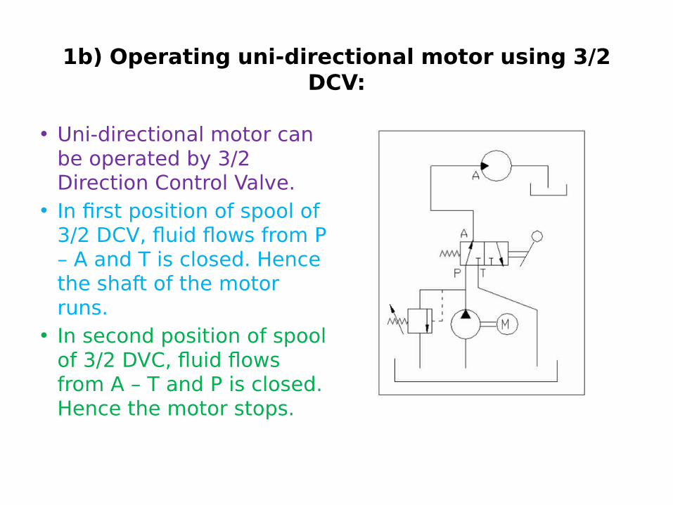
• Uni-directional motor can be operated by 3/2 Direction Control Valve.
• In first position of spool of 3/2 DCV, fluid flows from P – A and T is closed. Hence the shaft of the motor runs.
• In second position of spool of 3/2 DVC, fluid flows from A – T and P is closed. Hence the motor stops.

2a) Operating DAC using 4/2 DCV:
• 4/2 DCV has four ports namely inlet port “P”, exhaust port “T”, cylinder port “A” and cylinder port“B”.
• It has two positions of its spool.In first position of spool of 4/2 DCV, air flows from P – A and B – T. Hence the piston of DAC extends.
• In second position spool of 4/2 DVC, air flows from P – B and A – T. Hence the piston of DAC retracts.

Video 2

2b) Operating two SAC using one 4/2 DCV:
• 4/2 DCV has two cylinder ports namely, cylinder port “A” and cylinder port “B”.
• If there are two single acting cylinders we can connect each port to each SAC, so that, while one is extending the other will be retracting.
• 4/2 DCV has two positions of its spool.
• In first position of spool of 4/2 DCV, air flows from P – A and B – T. Hence the cylinder-1 extends and cylinder-2 retracts.
• In second position spool of 4/2 DVC, air flows from P – B and A – T. Hence the cylinder-2 extends and cylinder-1 retracts.
2c) Operating only one SAC using a 4/2 DCV
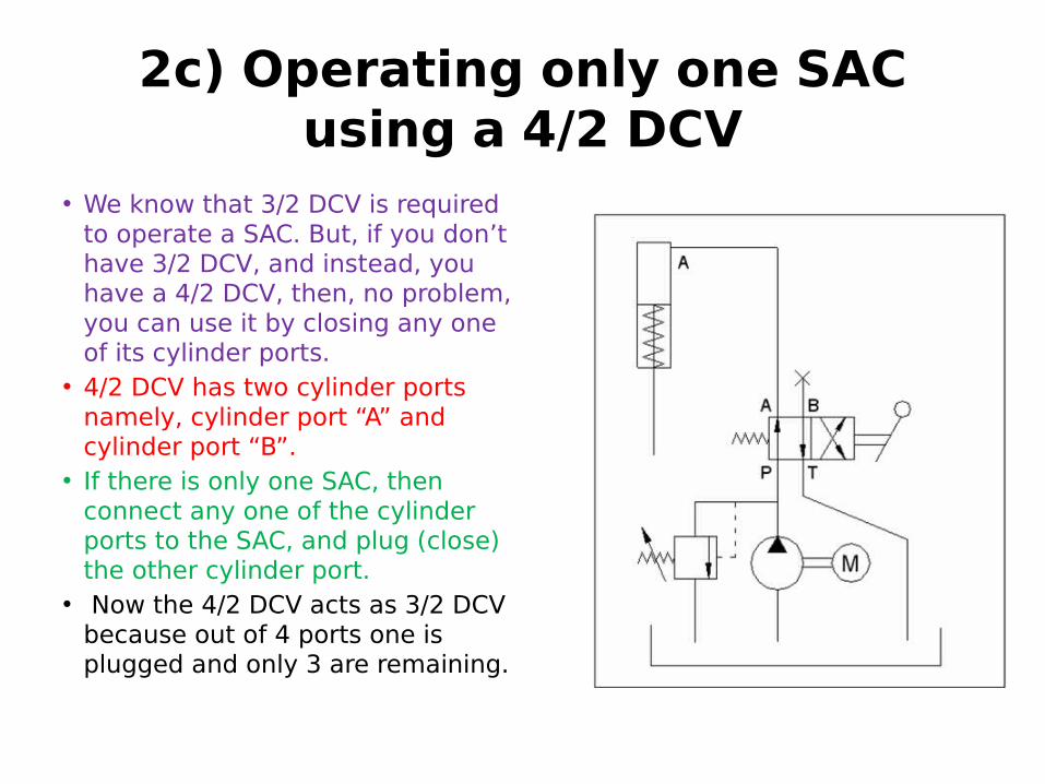
• We know that 3/2 DCV is required to operate a SAC. But, if you don’t have 3/2 DCV, and instead, you have a 4/2 DCV, then, no problem, you can use it by closing any one of its cylinder ports.
• 4/2 DCV has two cylinder ports namely, cylinder port “A” and cylinder port “B”.
• If there is only one SAC, then connect any one of the cylinder ports to the SAC, and plug (close) the other cylinder port.
• Now the 4/2 DCV acts as 3/2 DCV because out of 4 ports one is plugged and only 3 are remaining.

2c) Operating only one SAC using a 4/2 DCV
• 4/2 DCV has two positions of its spool.
• In first position of spool of 4/2 DCV, air flows from P – A and B & T are closed. Hence the SAC extends.
• In second position spool of 4/2 DVC, air flows from A – T and B & P are closed. Hence the SAC retracts.
3a) Operating DAC using 4/3 DCV:
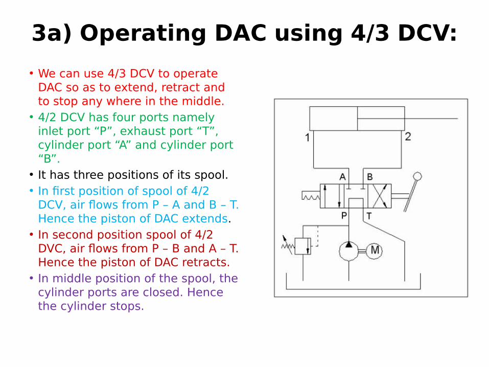
• We can use 4/3 DCV to operate DAC so as to extend, retract and to stop any where in the middle.
• 4/2 DCV has four ports namely inlet port “P”, exhaust port “T”, cylinder port “A” and cylinder port “B”.
• It has three positions of its spool.• In first position of spool of 4/2
DCV, air flows from P – A and B – T. Hence the piston of DAC extends.
• In second position spool of 4/2 DVC, air flows from P – B and A – T. Hence the piston of DAC retracts.
• In middle position of the spool, the cylinder ports are closed. Hence the cylinder stops.

3a) Operating DAC using 4/3 DCV:• In this example, the 4/3
DCV has closed type mid position.
• There are many different types of mid positions of 4/3 DCV, closed center, open center, tandem center, and others.
• All are having specific applications. Functioning of system should be studied and accordingly one should choose appropriate type of mid position.
3b) Operating bi-directional motor using 4/3 DCV:
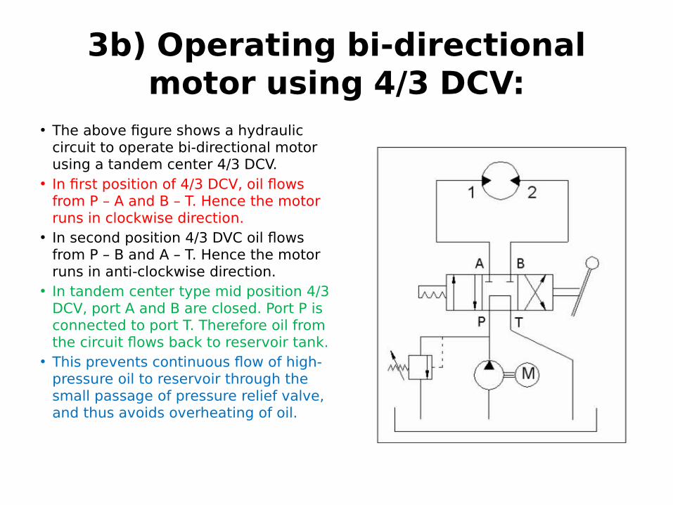
• The above figure shows a hydraulic circuit to operate bi-directional motor using a tandem center 4/3 DCV.
• In first position of 4/3 DCV, oil flows from P – A and B – T. Hence the motor runs in clockwise direction.
• In second position 4/3 DVC oil flows from P – B and A – T. Hence the motor runs in anti-clockwise direction.
• In tandem center type mid position 4/3 DCV, port A and B are closed. Port P is connected to port T. Therefore oil from the circuit flows back to reservoir tank.
• This prevents continuous flow of high-pressure oil to reservoir through the small passage of pressure relief valve, and thus avoids overheating of oil.

4) DUAL CONTROL (TWO HAND OPERATION) CIRCUIT:
• This is a safety circuit named as “two hand operation” or “dual control” of cylinder.
• Here, the operator has to engage both of his hands in operating the valves for making the DAC to extend.
• This prevents the chance of accident or injury to the hands of the operator.
• It is “AND” logic circuit. Definition of this logic is “output is present only when both input-A as well as input-B are present ”.
• Here, output means extension of DAC. Input-A means actuation of valve-1.
• input-B means actuation of valve-2.

4a) Two hand operation of SAC using two 3/2 valves:
• Actually, one 3/2 DCV is sufficient just to operate a SAC. But for safety of operator’s hands, the safety circuit consists of two 3/2 valves.
• Operator has to operate both of these valves together, then only the DAC extends.
• The circuit contains two NC 3/2 valves. NC means, “normally closed”.
• In normal position, the inlet port “P” is closed and cylinder port “A” is connected to exhaust port “T”.
• These two valves are connected in series, that is, the outlet port of first valve is connected to inlet port of second valve.
• When both of these valves are pressed together, fluid flows to SAC and the SAC extends.

4b) Two hand operation of SAC using twin pressure valve:
• Shuttle valve has AND logic function. If fluid under pressure is supplied through both of the two inlet ports, inlet port A or inlet port B, then only there will be supply from the outlet port C.
• Circuit consists of two NC 3/2 valves, valve-1 and valve-2. The outlet of valve-1 is connected to inlet-A and that of valve-2 is connected to inlet-B.
• The outlet-C of twin pressure valve is connected to SAC.
• When both of these valves are pressed together, fluid flows to SAC and the SAC extends.

4c) Two hand operation of DAC using two 3/2 valves:
• As we know, a 3/2 DCV has one cylinder port, where the DAC has two ports. Hence for operating DAC using 3/2 DCV, we need two 3/2 valves.
• Connect one valve to one port of cylinder and the other valve to other port. In figure, valve-1 is connected to head end port “H” and valve-2 is to rod end port “R”.
• Valve-1 is NC valve, that is, it is normally closed type valve. In normal position, the inlet port “P” is closed and cylinder port “A” is connected to exhaust port “T”.
• Valve-2 is NO valve, that is, it is normally open type valve. In normal position, the inlet port “P” is connected to cylinder port “B”, exhaust port “T” is closed.

4c) Two hand operation of DAC using two 3/2 valves:
• In normal position of these two valves,
• Fluid flows into DAC at rod end port “R” through valve-2 and it comes out at head end port “H” and exhausted through valve-1
• Hence, DAC retracts in normal position.
• For extending the cylinder, operator has to operate both of these valves together.
• When both valves are pressed together, then only the DAC extends.

5) OPERATING DAC USING 5/2 DCV:
• 5/2 DCV has five ports namely inlet port “P”, cylinder port “A” and cylinder port “B” exhaust port “T1”, exhaust port “T2”.
• 5/2 DCV has two positions of its spool.
• In first position of spool of 5/2 DCV, air flows from P – A and B – T2. Hence the piston of DAC extends.
• In second position spool of 5/2 DVC, air flows from P – B and A – T1. Hence the piston of DAC retracts.

6) AUTOMATIC CONTINUOUS OPERATION OF DAC:
• We can use either of the following two types of circuits for obtaining continuous reciprocation of piston of double acting cylinder
• By using limit switches and double solenoid 4/2 DCV:
• By using limit valves and double pilot 4/2 DCV:• By adjusting the position of limit switches or
limit valves, we can adjust the length and position of stroke of the cylinder. Hence these circuits are also called stroke control circuits.
6a) By using limit switches and double solenoid 4/2 DCV:
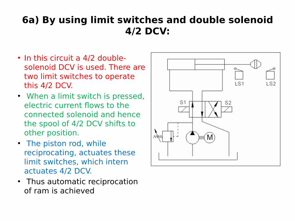
• In this circuit a 4/2 double-solenoid DCV is used. There are two limit switches to operate this 4/2 DCV.
• When a limit switch is pressed, electric current flows to the connected solenoid and hence the spool of 4/2 DCV shifts to other position.
• The piston rod, while reciprocating, actuates these limit switches, which intern actuates 4/2 DCV.
• Thus automatic reciprocation of ram is achieved

6a) By using limit switches and double solenoid 4/2 DCV:
• In first position of 4/2 DCV, fluid flows from P – A and B – T. hence the cylinder extends.
• By the end of extension, the cam fitted to piston rod presses the limit switch “LS2”.
• Hence, electric current flows to solenoid “S2” and due to this, the spool of 4/2 DCV shifts to second position.
• In second position 4/2 DVC fluid flows from P – B and A – T.
• hence the cylinder retracts. By the end of retraction, the cam presses the limit switch “LS1”.
• Hence, electric current flows to solenoid “S1” and due to this, the spool of 4/2 DCV shifts to first position. And the cycle continues.

Video 3

6b) By using limit valves and double pilot 4/2 DCV:
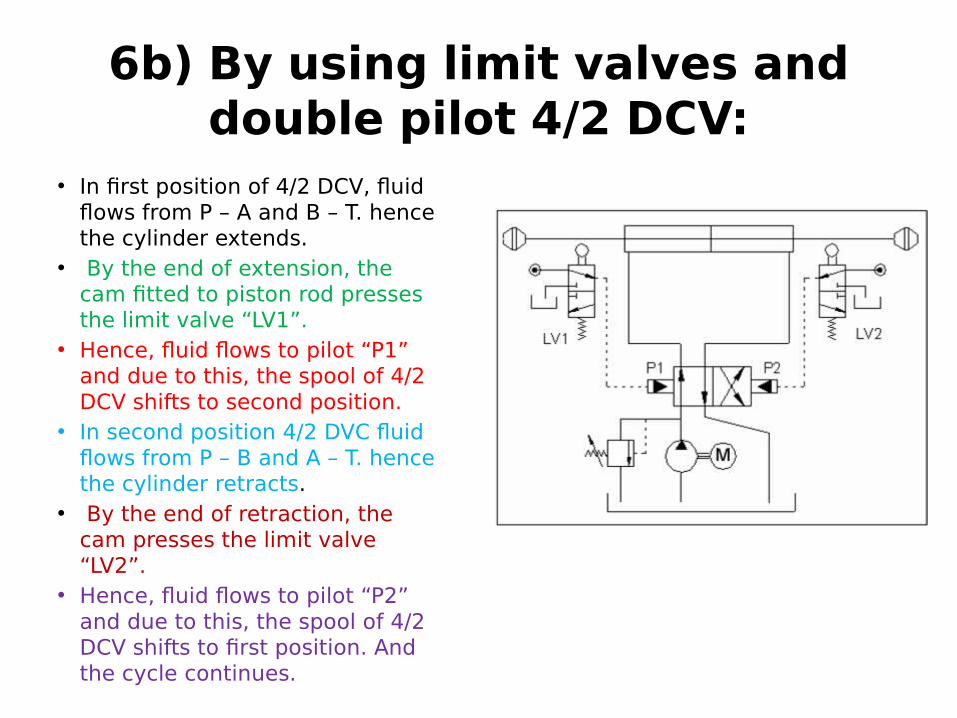
• In this circuit a 4/2 double-pilot DCV is used. There are two cam operated 3/2 DCV which are called “limit valves” to operate this 4/2 DCV.
• When a limit valve is pressed, fluid flows to the connected pilot and hence the spool of 4/2 DCV shifts to other position.
• The piston rod, while reciprocating, actuates these limit valves, which intern actuates 4/2 DCV.
• Thus automatic reciprocation of DAC is achieved.
6b) By using limit valves and double pilot 4/2 DCV:
• In first position of 4/2 DCV, fluid flows from P – A and B – T. hence the cylinder extends.
• By the end of extension, the cam fitted to piston rod presses the limit valve “LV1”.
• Hence, fluid flows to pilot “P1” and due to this, the spool of 4/2 DCV shifts to second position.
• In second position 4/2 DVC fluid flows from P – B and A – T. hence the cylinder retracts.
• By the end of retraction, the cam presses the limit valve “LV2”.
• Hence, fluid flows to pilot “P2” and due to this, the spool of 4/2 DCV shifts to first position. And the cycle continues.

7) SPEED CONTROL CIRCUITS:
• Speed of hydraulic or pneumatic actuators can be controlled using flow control valves. Varying the rate of flow of fluid in the circuit will vary the time taken to fill the cylinder and thus vary the time of completion of the stroke.
• In meter-in (throttling-in) control, the rate of flow of fluid is controlled at entrance of the actuator.
• In meter-out (throttling-out) control, the rate of flow is controlled at exit.
• In bleed of control, the rate of floe of fluid is controlled in by-pass line, which is leading towards oil reservoir.
• Bleed-off control is not preferred for pneumatic systems because compressed air is not to be wasted like that by releasing simply to atmosphere.

7a) Meter-in circuit or throttling-in circuit: (for extension of DAC)
• In meter-in circuits, the rate of flow of fluid into the cylinder is controlled by flow control valve. FCV is placed at inlet of the cylinder. Head end port “H” is inlet for extension and rod end port “R” is inlet for retraction.
• The above circuit is meter-in control circuit for extension of DAC.
• In first position of 4/2 DCV, fluid flows from P to A. But this flow is through flow control valve. Hence the piston extends slowly. Fluid, which is there in the cylinder, flows out from B to T.
• In second position 4/2 DVC fluid flows from P – B and A – T. this flow is through check valve. I.e. it is free flow. Hence the piston retracts at high speed, which is not controlled.

7a) Meter-in circuit or throttling-in circuit: (for extension of DAC)
• Meter-in control is used for opposing loads only.
• It can’t prevent running away loads.
• This is because the head end port has free path towards reservoir.
• Running away load will pull the piston and piston can’t resist that.

7b) Meter-out circuit or throttling-out circuit: (for extension of DAC)
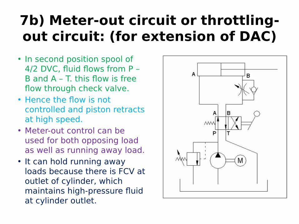
• In meter-out circuits, the rate of flow of fluid coming out of the cylinder is controlled by flow control valve. FCV is placed at outlet of the cylinder.
• Rod end port “R” is outlet for extension and head end port “H” is outlet for retraction.
• The above circuit is meter-out control circuit for extension of DAC.
• In first position of spool of 4/2 DCV, fluid flows from P – A and B – T.
• this flow is through flow control valve, the flow is controlled and hence piston extends slowly,

Video 4
7b) Meter-out circuit or throttling-out circuit: (for extension of DAC)
• In second position spool of 4/2 DVC, fluid flows from P – B and A – T. this flow is free flow through check valve.
• Hence the flow is not controlled and piston retracts at high speed.
• Meter-out control can be used for both opposing load as well as running away load.
• It can hold running away loads because there is FCV at outlet of cylinder, which maintains high-pressure fluid at cylinder outlet.

Video 5
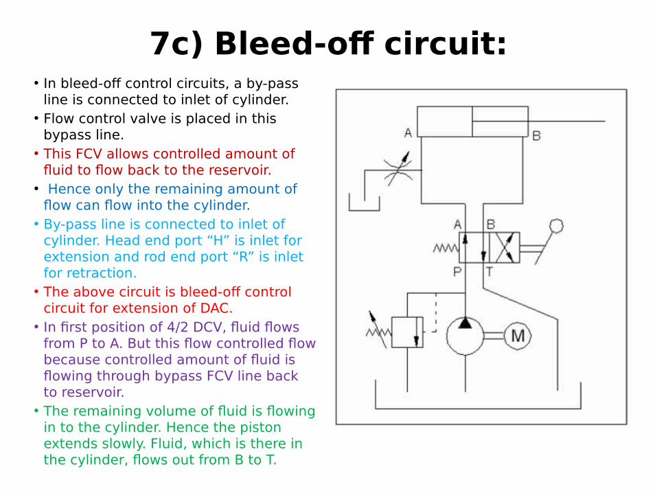
7c) Bleed-of circuit:• In bleed-off control circuits, a by-pass
line is connected to inlet of cylinder. • Flow control valve is placed in this
bypass line. • This FCV allows controlled amount of
fluid to flow back to the reservoir.• Hence only the remaining amount of
flow can flow into the cylinder.• By-pass line is connected to inlet of
cylinder. Head end port “H” is inlet for extension and rod end port “R” is inlet for retraction.
• The above circuit is bleed-off control circuit for extension of DAC.
• In first position of 4/2 DCV, fluid flows from P to A. But this flow controlled flow because controlled amount of fluid is flowing through bypass FCV line back to reservoir.
• The remaining volume of fluid is flowing in to the cylinder. Hence the piston extends slowly. Fluid, which is there in the cylinder, flows out from B to T.
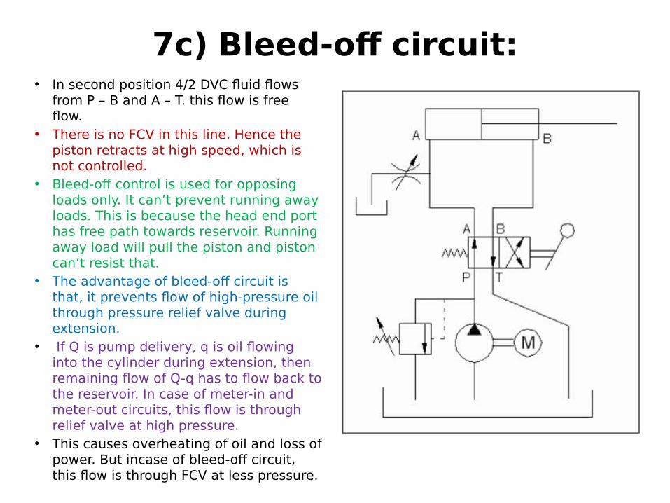
7c) Bleed-of circuit:• In second position 4/2 DVC fluid flows
from P – B and A – T. this flow is free flow.
• There is no FCV in this line. Hence the piston retracts at high speed, which is not controlled.
• Bleed-off control is used for opposing loads only. It can’t prevent running away loads. This is because the head end port has free path towards reservoir. Running away load will pull the piston and piston can’t resist that.
• The advantage of bleed-off circuit is that, it prevents flow of high-pressure oil through pressure relief valve during extension.
• If Q is pump delivery, q is oil flowing into the cylinder during extension, then remaining flow of Q-q has to flow back to the reservoir. In case of meter-in and meter-out circuits, this flow is through relief valve at high pressure.
• This causes overheating of oil and loss of power. But incase of bleed-off circuit, this flow is through FCV at less pressure.

Video 6

8) SEQUENCING CIRCUITS USING SEQUENCE VALVES:
• In hydraulic circuits, sequence valve is used to perform two operations in sequence one after the other.
• For example first cylinder-1 will extend and after that cylinder-2 will extend.
• It has an adjusting screw, a spring and a conical poppet, which are, mounted in side the valve body as shown in figure.
• The valve has one inlet port and two outlets, outlet port “1” and outlet port “2”.

8a) Circuit to operate two SAC in sequence
• When lever of 3/2 DCV is in first position, fluid under pressure (oil or air) is supplied to inlet port of sequence valve.
• It flows directly to outlet port1. • Hence cylinder1 extends first.
By the end of extension of cylinder1, pressure in the line increases and hence the poppet of sequence valve lifts off from its seat to allow fluid to flow to port2, hence cylinder2 extends.
• When the lever of 3/2 DCV is shifted to second position, both cylinders retract simultaneously.

Video 7

Example OF DRILLING MACHINE• The above figure shows the hydraulic circuit using two sequence
valves to control two operations performed in a proper sequence in both directions. The circuit uses manually operated 4/2 DCV.
• In the example shown in the above figure, first the work piece should be held firmly, and then drilling should be done. After this the drill bit should be removed from work piece and then the work piece should be released by the vice.
• In first position of 4/2 DCV, oil flows to cylinder C1, hence C1 extends, the movable jaw of the vice holds the work piece. By the completion of extension of C1, pressure in the line increases hence the sequence valve V1 opens to allow oil to flow to cylinder C2. Hence C2 extends to move the drill bit down wards.
• In second position of 4/2 DCV, oil flows to cylinder C2, hence C2 retract, the drill bit is removed from the work piece. By the completion of retraction of C2, pressure in the line increases hence the sequence valve V2 opens to allow oil to flow to cylinder C1. Hence C1 retracts to move the movable jaw back wards to release the work piece.

Example OF DRILLING MACHINE

Video 8

9) SEQUENCING CIRCUITS USING LIMIT VALVES:
• In the above examples, sequencing is executed due to the pressure increase at the end of operations. These are pressure-controlled sequencing circuits.
• But now what we study is position-controlled sequencing circuits, here the sequencing is achieved due to the position of piston.
• Limit valve is a cam operated spring return 3/2 direction control valve.
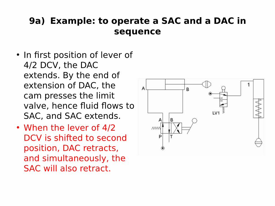
9a) Example: to operate a SAC and a DAC in sequence
• In first position of lever of 4/2 DCV, the DAC extends. By the end of extension of DAC, the cam presses the limit valve, hence fluid flows to SAC, and SAC extends.
• When the lever of 4/2 DCV is shifted to second position, DAC retracts, and simultaneously, the SAC will also retract.

9b) Example: to operate two DAC in sequence:
• By the end of extension of first DAC, the cam press limit valve, hence fluid flows to second DAC, and second DAC extends.
• By the end of retraction of first DAC, the cam press limit valve, hence fluid flows to second DAC, and second DAC retracts.

10) SEQUENCING CIRCUITS USING LIMIT SWITCHES:
• Limit switch is an electrical switch which when pressed by any moving element, it makes the electrical connection, and thus electric current flows to the electric device such as motor, solenoid coil, etc.
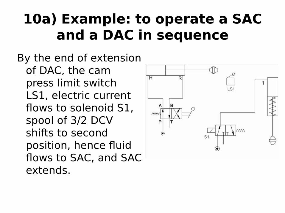
10a) Example: to operate a SAC and a DAC in sequence
By the end of extension of DAC, the cam press limit switch LS1, electric current flows to solenoid S1, spool of 3/2 DCV shifts to second position, hence fluid flows to SAC, and SAC extends.

10a) Example: to operate a SAC and a DAC in sequence
• By the end of extension of first DAC, the cam press limit switch, hence fluid flows to port-1 of second DAC, and second DAC extends.
• By the end of retraction of first DAC, the cam press limit switch, hence fluid flows to port-2 of second DAC, and second DAC retracts

11) SYNCHRONIZING CIRCUIT
• Synchronization means making two or more number of cylinders to move simultaneously, together.

example-1
• In example-1, two cylinders are connected in parallel to a 4/2 DCV. It looks like a synchronous circuit, but it is not so.
• The two cylinders move together only if the opposing loads on them are equal.
• If opposing forces are unequal, then the cylinder with less opposing force will extend first.

example-2
• In example-2 the two cylinders are hooked in series, the outlet of one is connected to inlet of other.
• Now, even if the opposing forces on them are unequal, they move (extend) together

UNLOADING CIRCUIT• Unloading the pump: Unloading valve is used to unload a pump
or accumulator. • In many operations, the cylinder has to extend fast at no load and
it should extend slowly when there is high load.• For example consider punching operation. The actual punching
starts only when the punch touches the work-piece. • The length of stroke for actual punching operation is very less,
equal to the thickness of the work-piece. Remaining major portion of stroke is for advancement of punch towards work-piece.
• Advancement of punch should be fast; otherwise the work piece does not shear properly.
• That says, we require “less force-high speed” at no load for advancement of punch, and “high force-less speed” during actual punching.

• In the circuit given below, two pumps are used for obtaining high speed, one is large volume pump and the other is small volume pump, we shall name them as big pump and small pump.
• Big pump takes care of the large quantity of low-pressure oil required during fast extension of cylinder (i.e. for advancement of punch).
• Small pump delivery at high pressure is necessary for performing actual punching operation.

• So, we use two pumps, of which, one is large volume pump. During idle period of punch, i.e. at the ends of its extension or retraction strokes, oil is not required by the cylinder, but pumps are continuously delivering oil.
• Large volume pump should be unloaded at low pressure, other wise oil becomes hot and its properties will be spoiled.
• The pilot operated unloading valve is set for low pressure, and its pilot is connected to the system. It opens if the system pressure rises beyond this preset pressure and releases the delivery of large pump to reservoir.
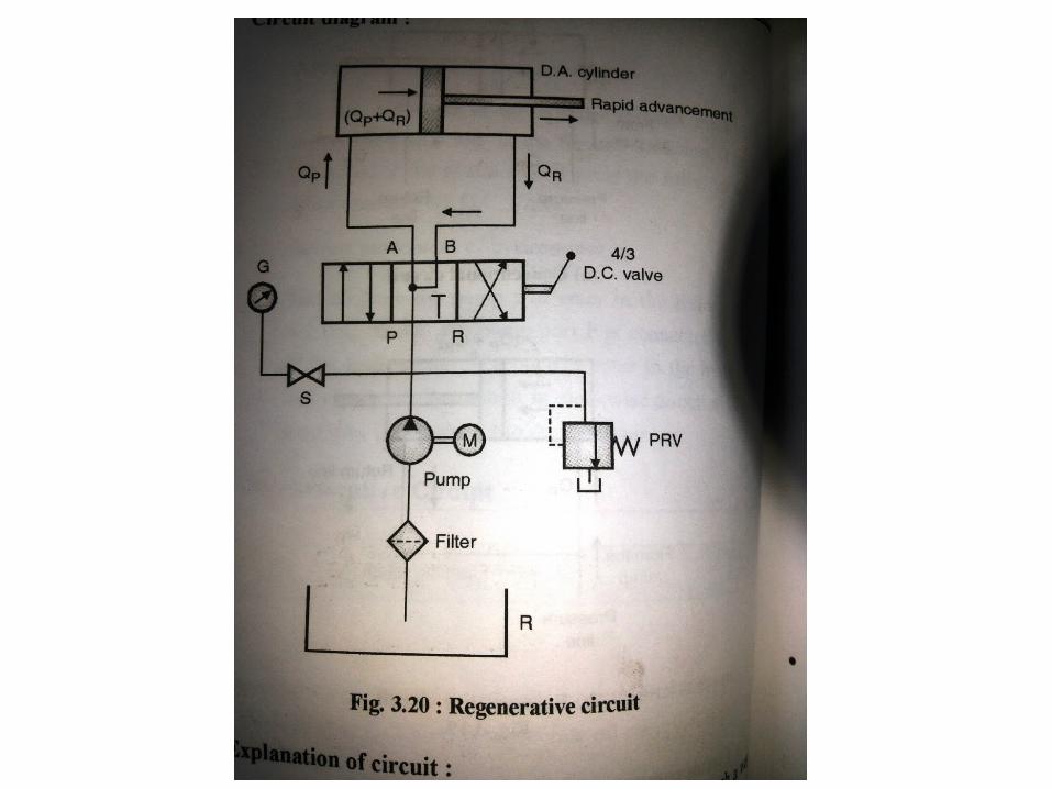
REGENERATIVE CIRCUIT
When the return line of the actuator is connected to the pressure line with the help of D.C. valve to generate oil energy, it is called as regenerative circuit.
In the conventional circuits, the oil from the return line will be drain out to the reservoir.
It is low pressure oil and again recirculated with the help of pump.
Instead of drain out the low pressure oil, it is connected to the pressure line to add more energy in the pressure line from the pump.
It increases the speed of cylinder in its forward motion (rapid advancement.)

14) HYDRAULIC SHAPER (GEAR SHAPING):
• Shaping is a machining process, in which, a cutting tool reciprocating on the stationary work-piece.
• The cutting tool cuts the metal by shearing action.
• The cutting tool is fitted in the tool-post, tool-post to clapper box, clapper box to cross slide, and cross slide to ram.
• Reciprocation of ram causes the tool to cut the metal.

14) HYDRAULIC SHAPER (GEAR SHAPING):

• The hydraulic shaping machine is shown in figure. Its ram is mounted on a double rod end DAC.
• The cutting stroke of the ram should be slow and the return stroke should be fast. For this, we can choose meter out circuit.
• Continuous reciprocation of ram can be obtained either by using solenoid DCV or by using pilot-operated DCV.
• You need limit switches if solenoid DCV is chosen and limit valves if pilot-operated DCV is chosen.
• In the above example, solenoid DCV and limit switches are used. • 4/2 double-solenoid DCV is used with two limit switches on either end of the
piston rod. • The piston rod, while reciprocating, actuates these limit switches, which
intern actuates 4/2 DCV. • Thus automatic reciprocation of ram is achieved.• In first position of 4/2 DCV, oil flows from P – A. this flow is through check
valve. Hence the piston moves fast. Oil, which is present in right side of piston in the cylinder, flows from B – T.
• In second position 4/2 DVC oil flows from P – B and A – T. this flow is through flow control valve. I.e. it is controlled flow. Hence the piston moves slowly.
• The stroke length and position of stroke can be easily adjusted by adjusting the position of limit switches. Speed of cutting stroke can be adjusted by adjusting the FCV opening.

Video 9

15) HYDRAULIC MILLING MACHINE OR HYDRAULIC SURFACE GRINDING MACHINE:

• In milling machine or surface grinder machine, the work-piece is clamped on the machine table. The machine table is made to reciprocate using a double rod end type DAC. That is the work-piece is made to reciprocate against a rotating multi-point cutting tool (milling cutter or grinding wheel). Thus the cutting tool cuts the metal.
• Continuous reciprocation of ram can be obtained either by using solenoid DCV or by using pilot-operated DCV. You need limit switches if solenoid DCV is chosen and limit valves if pilot-operated DCV is chosen.
• In this example, pilot operated DCV and limit valves are used.• 4/2 double-pilot DCV is used with two limit valves on either end of the
piston rod. The piston rod, while reciprocating, actuates these limit valves, which intern actuates 4/2 DCV. Thus automatic reciprocation of ram is achieved.
• In first position of 4/2 DCV, oil flows from P – A and B – T. Hence the piston extends.
• In second position 4/2 DVC, oil flows from P – B and A – T. Hence the piston retracts.
• Flow control valve is placed in return line to the reservoir, hence it is meter out circuit with same speed in both strokes.