oil coolers - experts in hydraulic & pneumatic … industrial...industrial air-cooled oil...
TRANSCRIPT

130 Copyright © 2004 American Industrial Heat Transfer, Inc. tel: 1 (847) 731-10003905 Route 173 Zion, IL 60099 www.aihti.comfax: 1 (847) 731-1010
note: AIHTI reserves the right to make reasonable design changes without notice.
131Copyright © 2004 American Industrial Heat Transfer, Inc. tel: 1 (847) 731-10003905 Route 173 Zion, IL 60099 www.aihti.comfax: 1 (847) 731-1010
note: AIHTI reserves the right to make reasonable design changes without notice.
• Thermal capacity to 100 hp (75 Kw).
• Computerized selection program.
• Standard ports NPT, optional SAE straight
thread or flange connections.
• Optional: built-in bypass relief valve.
• Operating temperature of 400° F and pressure
of 300PSI.
Air Cooled
OIL COOLERS
AC - ACF - ACHM SERIES
• Custom designs to fit your needs.
• Cools: Fluid Power Systems, Lubrication
Systems, Hydraulic Presses, Gear Drives,
Torque Convertors, Machine Tools, Etc...
ACF SERIES
AC SERIES
ACHM SERIES
®

132 Copyright © 2004 American Industrial Heat Transfer, Inc. tel: 1 (847) 731-10003905 Route 173 Zion, IL 60099 www.aihti.comfax: 1 (847) 731-1010
note: AIHTI reserves the right to make reasonable design changes without notice.
133Copyright © 2004 American Industrial Heat Transfer, Inc. tel: 1 (847) 731-10003905 Route 173 Zion, IL 60099 www.aihti.comfax: 1 (847) 731-1010
note: AIHTI reserves the right to make reasonable design changes without notice.
AC, ACF & ACHM Series overview
AC SERIES with electric drive Industrial air-cooled oil coolers, standard duty three row brazed tube industrial series heat exchangers with direct electric drive cool-ing fan, OSHA guard, and air directing louvers.Rated operating tem-perature of 400oF at 300 PSIG. Services standard flow rates from 2 to 120 GPM. Thermal capacity up to 100 hp (75Kw). NPT, flange, or SAE straight thread port connections. Optional built-in bypass relief valve 30 PSI or 65 PSI. Can be modified to meet your requirements. Suitable for most hydraulic oils, lubrications oils, synthetic compres-sor oils, phosphate ester, ethylene glycol, and many other fluids compatible with listed material.
ACHM SERIES with hydraulic drive Industrial air-cooled oil coolers, standard duty three row brazed tube industrial series heat exchangers with hydraulic drive cooling fan, OSHA guard, and air directing louvers. Rated operating temperature of 400oF at 300 PSIG. Services standard flow rates from 2 to 120 GPM. Thermal capacity up to 100 hp (75Kw). NPT, flange, or SAE straight thread port connections. Optional built-in bypass relief valve 30 PSI or 65 PSI. Can be modified to meet your requirements. Suitable for most hydraulic oils, lubrications oils, synthetic compressor oils, phosphate ester, ethylene glycol, and many other fluids compatible with listed material.
ACF SERIES with electric drive Industrial air-cooled oil coolers, standard duty three row brazed tube industrial series heat exchangers with washable internal filter located between the fan and core, direct electric drive cooling fan, OSHA guard, and air directing louvers. Washable filter helps prevent airborne dust and debris from collecting on the core fins for continued optimum performance. Filter can be easily removed within minutes from the filter track, cleaned, and replaced for continued service. Rated operating temperature of 400oF at 300 PSIG. Thermal capac-ity up to 100 hp (75Kw). Optional built-in bypass relief valve 30 PSI or 65 PSI. Can be modified to meet your requirements. The ACF series can be used in environments such as Sawmills or foundries, etc...where excessive airborne dust or debris may be present.
AOCH SERIES Industrial air-cooled oil coolers, dimensionally similar to AC & ACHM Series with higher performance. High performance six row rolled or brazed tube industrial series heat exchangers with direct electric drive cooling fan, OSHA guard, air directing louvers and Servicable Core ®. Rated operating temperature of 400oF at 300 PSIG. Can be modified to meet your requirements. Suitable for most hydraulic oils, lubrications oils, synthetic compressor oils, phosphate ester, ethylene glycol, and many other fluids compatible with listed material.
(See Page 145)

132 Copyright © 2004 American Industrial Heat Transfer, Inc. tel: 1 (847) 731-10003905 Route 173 Zion, IL 60099 www.aihti.comfax: 1 (847) 731-1010
note: AIHTI reserves the right to make reasonable design changes without notice.
133Copyright © 2004 American Industrial Heat Transfer, Inc. tel: 1 (847) 731-10003905 Route 173 Zion, IL 60099 www.aihti.comfax: 1 (847) 731-1010
note: AIHTI reserves the right to make reasonable design changes without notice.
AC, ACF & ACHM Series construction
HIGH PERFORMANCE TURBULATOR Exclusive American Industrial Turbulators (installed in ev-
ery flow tube) increase heat transfer by more than 100%.
American Industrial Turbulators eliminate the laminar flow
condition normally associated with other smooth tube heat
exchangers. High viscosity hydraulic and lubricating oils are
easily cooled by this new state-of-the-art turbulator.
SUPERIOR COOLING FINS
Seamless copper tubes are mechanically bonded
to highly efficient aluminum cooling fins. Die-formed fin
collars provide a durable precision fit for maximum heat
transfer.
Custom fin design forces air to become turbulent and
carry heat away more efficiently than old flat fin designs.
TANKS
State-of-the-art 21st century high temperature brazing
method insures permanent bond and positive contact of
tube to manifold, eliminating leaks and providing maximum
service life.
CONSTRUCTION MATERIALS & RATINGS
Copper
Aluminum
Steel
Steel
Steel
Steel
Aluminum with steel hub
Zinc plated steel
Operating Pressure
Operating Temperature
Max. Flow Internal Relief
Max. Fan Over-speed
Max. Ambient Conditions
Altitude
Carbon Steel
Copper
Brass
Brass
Brass
316L Stainless Steel, Galvanized Steel
Plastic, Non-sparking
Standard Construction Materials Optional Construction Materials Standard Unit Ratings
Tubes
Fins
Turbulators
Manifold
Connection pipes
Cabinet & frame
Fan Blade
Fan Guard
300 psig
400 oF
38 gpm
10 %
104 oF
0-3300 ft.

134 Copyright © 2004 American Industrial Heat Transfer, Inc. tel: 1 (847) 731-10003905 Route 173 Zion, IL 60099 www.aihti.comfax: 1 (847) 731-1010
note: AIHTI reserves the right to make reasonable design changes without notice.
135Copyright © 2004 American Industrial Heat Transfer, Inc. tel: 1 (847) 731-10003905 Route 173 Zion, IL 60099 www.aihti.comfax: 1 (847) 731-1010
note: AIHTI reserves the right to make reasonable design changes without notice.
AC, ACF & ACHM Series performance
Horsepower to be removed (HP) x 2545 x Cv °F (Oil Leaving] - Ambient Air Entering) Fs =
OIL PRESSURE DROP (PSI) CODE
BTUhr °F
=
Note: When a model selection has been made, record whether the selection was from the one pass curve or the two pass curve so that the unit can be properly plumbed. Incorrect installation can seriously affect the performance.
PERFORMANCE CALCULATION
]Represents desired fluid leaving the cooler.
5
10
15
20
25
30
35
40
3000
2000
800
600500
400
300
100
200
80
2 3 4 5 6 7 8 9 10 20 30 40 50 60 70 80 90 100 200
1000
ONE PASS
GPM
Fs
B
B
A
A
C
C
D
D
E
E
F
F
G
G
H
H
I
I
I
J
BA
C D E F G H I J
J
BA
C D E F G H
BA
C D E F G H I
BA
C D E F G H
I
BA
C D E F G H
I
BA
C D E F G H
D = 4 PSIE = 5 PSIF = 10 PSI
G = 15 PSIH = 20 PSI I = 25 PSI
J = 30 PSIK = 35 PSIL = 40 PSI
A = 1 PSIB = 2 PSIC = 3 PSI
5
10 15
20
25
30
35
403000
50004000
2000
800
600500400
300
200
2 3 4 5 6 7 8 9 10 20 30 40 50 60 70
1000
80100
TWO PASS
GPM
Fs
B
B
A
A
C
C
D
D
E
E
F
F
G
G
H
H
I
I
I J K
J K
BAC D E F G H I J
J K
K
L
I J K L
BA
C D E F G H
BA
C D E F G H I
BA
C D E F G H
I
BAC D E F G H
IB
AC D E F G H

134 Copyright © 2004 American Industrial Heat Transfer, Inc. tel: 1 (847) 731-10003905 Route 173 Zion, IL 60099 www.aihti.comfax: 1 (847) 731-1010
note: AIHTI reserves the right to make reasonable design changes without notice.
135Copyright © 2004 American Industrial Heat Transfer, Inc. tel: 1 (847) 731-10003905 Route 173 Zion, IL 60099 www.aihti.comfax: 1 (847) 731-1010
note: AIHTI reserves the right to make reasonable design changes without notice.
AC, ACF & ACHM Series selection
SizingThe performance curves provided are for petroleum oil at 50 ssu viscosity. However, fluids with characteristics other than the above mentioned may be used by applying a correction factor.
Heat LoadIf the heat load is unknown, a horsepower value can be calculated by first determining the systems total potential. For a basic hydraulic system, it is helpful to know whether the system is open loop (with a large res-ervoir) or closed loop (normally on mobile equipment, with a very small reservoir). System potentials may be calculated quickly by using one of the two methods below.
There are some system parameters that will be required to properly accomplish the sizing calculations. Without system parameters, it is difficult to determine the optimal heat exchanger size. Normally many of the system parameters can be found on hydraulic schematics or on tags located on the actual equipment. Following are some basic parameters that you should try to acquire before attempting the sizing calculations. However, it is not necessary to have every parameter listed below.
• Main system flow rate (gpm) & operating pressure (psi). • Electric motor HP driving hydraulic pump (if more than one add up
the Hp for all). • Desired temperature (°F). • Fluid type (SAE 10, 20, 30, etc....). • Ambient air temperature (warmest day). • Desired fan drive (hydraulic, electric, 12-24V DC, etc...). • BTU's or HP to be cooled (normally given for lubrication systems). • Maximum pressure drop allowed through the heat exchanger. • Space available for heat exchanger (LxWxH). • External air condition (dirty, papers,etc…).
Method 1Normally used for open loop circuits. Multiply the main hydraulic sys-tems Electric Motor Name plate Horsepower by a heat removal factor (normally 30-50%).
Example: 50 HP motor x 0.3 = 15 HP heat load
Method 2Normally used when the HP input potential is unknown or for mobile ap-plications where diesel engines operate the entire system.
Multiply system pressure by the flow rate of the main system divided by 1714 equals system potential (HP). Multiply the system HP by a heat removal factor (Normally 25-35%). Note: In some closed loop systems only a portion of the total system flow is directed through the heat ex-changer. This may affect the cooler selection process substantially. You may contact our factory for additional technical assistance.
Example:
Determining Fs valueTo determine the proper size heat exchanger for your application, use the following equation to first determine the (Fs) factor:
Fs =
Example: Heat load = 8.75 HP Cv = 1.14 (SAE 20) determined from chart. [Located on page 5.] Desired operating temperature = 120 ºFAmbient air temp. = 100 ºF
Fs = = 1269
SelectionTo select a model, locate the flow rate (GPM) at the bottom of the flow vs Fs graph (on page 4). Proceed upward until the GPM flow rate intersects with the calculated Fs. The curve closest above the intersection point will meet these conditions.
Example: Fs = 1269 = Model = AC,ACHM,ACF - 35 GPM = 40 PASSES = 1
Pressure differentialsDetermine the oil pressure drop from the curves as indicated. For vis-cosities other than 50 ssu, multiply the actual indicated pressure drop for your GPM flow by the value shown in the pressure differential curve for your viscosity value.
Example: Model 35 @ 40 gpm & 50 ssu -1 pass curve- Indicated pressure drop 4.2 psi (Approx) { 4.2 psi x 2.8Cp (for SAE-20 oil) } = 11.76 corrected psi
(2000 psi x 30 gpm) = [35 HP x .25] = 8.75 HP heat load _______________ 1714
{ heat load (HP) x 2545 x Cv } ______________________{ °F (oil leaving - air entering) }
{ 8.75 x 2545 x 1.14 } ________________{ 120 °F - 100 °F }
Cv VISCOSITY CORRECTION FACTORS
ISO
22
SA
E 3
0
SA
E 1
0
SA
E 5
1.381.321.271.241.191.161.040.98
1.251.201.171.131.111.091.010.97
1.151.121.101.081.051.040.990.96
1.451.401.351.291.251.221.070.99
1.111.091.061.041.031.010.980.95
50%
ETH
YLE
NE
GLY
CO
L&
WA
TER
PO
LYG
LYC
OL
0.920.890.880.850.840.830.790.76
PHO
SPH
ATE
ES
TER
0.830.800.790.770.760.740.710.69
0.850.840.840.830.820.820.800.79
Average
Liquid
Temperature
100110120130140150200250
ISO
32
1.081.061.041.031.021.020.980.95
ISO
46
1.141.131.111.091.081.060.990.96
ISO
68
1.181.161.141.131.101.091.000.96
ISO
100
1.261.251.201.171.161.131.010.96
ISO
150
1.371.311.271.241.201.171.020.97
ISO
220
1.431.391.351.301.261.221.080.99
ISO
320
1.561.481.401.341.301.271.091.01
SA
E 4
0
MIL
-L-7
808
1.191.141.091.051.031.010.980.97
SA
E 2
0
1.841.671.531.441.391.331.141.02
Cp PRESSURE DROP CORRECTION FACTORS
ISO
22
SA
E 3
0
SA
E 1
0
SA
E 5
6.405.104.203.402.902.501.400.97
4.403.603.002.602.231.901.200.92
2.402.101.801.601.501.300.960.82
8.806.705.604.503.703.101.601.05
2.001.701.501.401.301.200.930.81
50%
ETH
YLE
NE
GLY
CO
L&
WA
TER
PO
LYG
LYC
OL
3.002.402.101.901.901.701.201.00
PHO
SPH
ATE
ESTE
R
3.502.902.502.202.001.901.301.05
0.7300.7200.7090.6980.6860.6760.6350.556
Average
Liquid
Temperature
100110120130140150200250
ISO
32
1.071.041.020.990.970.950.890.85
ISO
46
1.531.451.381.301.231.170.990.93
ISO
68
1.821.721.601.491.381.301.080.96
ISO
100
2.542.352.151.941.751.611.181.03
ISO
150
4.193.733.262.802.382.041.331.11
ISO
220
6.445.704.914.143.472.901.591.21
ISO
320
9.388.337.236.195.204.351.741.22
SA
E 4
0
MIL
-L-7
808
1.261.201.141.081.030.980.900.83
SA
E 2
0
13.5611.63 9.73 7.80 6.11 4.77 1.95 1.23

136 Copyright © 2004 American Industrial Heat Transfer, Inc. tel: 1 (847) 731-10003905 Route 173 Zion, IL 60099 www.aihti.comfax: 1 (847) 731-1010
note: AIHTI reserves the right to make reasonable design changes without notice.
137Copyright © 2004 American Industrial Heat Transfer, Inc. tel: 1 (847) 731-10003905 Route 173 Zion, IL 60099 www.aihti.comfax: 1 (847) 731-1010
note: AIHTI reserves the right to make reasonable design changes without notice.
AG
KN
J
D1.25
ApproximateE
1.75 1.6210.36 0.38
0.56"Dia. Mounting Hole (6x)M *
2
B
F
HC
10.50
9.88
5.25 6.31
2.31
0.62
0.75
L
Fan
rota
tion
1
3
Air Flow
NAMEPL
AC Series dimensions
Notes:1) Removable base mounting brackets are supplied with unit at no
additional charge.2) 1/2-12 UNC-2B Tabs, 4 points, 8 points on models AC - 30,35 & 40
(top & bottom) for optional mounting purposes.3) Motor mounting bracket is rotated 90 degrees on AC - 5 & 10
units.
Model MNPT
LKJHFDCBA G
DIMENSIONS (inches)M
SAE7.69
8.88
11.50
14.00
19.25
23.19
25.81
32.38
8.31
12.50
13.88
17.19
20.19
25.13
27.31
35.13
11.81
13.13
15.75
18.38
23.63
27.56
30.19
36.75
14.81
19.00
20.38
23.81
26.68
31.63
33.81
41.63
9.19
10.50
13.12
15.75
21.00
24.94
27.56
34.12
11.69
15.88
17.25
20.56
23.56
28.50
30.69
38.50
17.56
17.13
17.44
17.56
17.56
17.63
20.75
19.63
5.90
6.56
7.88
9.19
11.81
13.78
15.09
18.38
16.81
21.00
22.38
25.81
28.68
33.63
35.81
43.63
12.94
17.13
18.50
21.81
24.81
29.75
31.94
39.75
____
____
____
____
____
11.00
11.00
13.25
1.00
1.00
1.00
1.25
1.25
1.25
1.25
1.25
AC - 5 -
AC - 10 -
AC - 15 -
AC - 20 -
AC - 25 -
AC - 30 -
AC - 35 -
AC - 40 -
16 SAE1 5/16 -
12UN-2B Thread
20 SAE1 5/8 -
12UN-2B Thread
E
4) Louvers are manually adjustable. However, all units are available with a screen front as an option (specify when ordering).
5) All units are available with an optional preset 30 or 65-psi pressure bypass valve. (see note "i" in maintenance on page 143)
6) All units can be connected in one or two pass configuration. Refer to piping instructions for detailed operating and maintenance informa-tion.
AC - 35 - 3 - S - R65 - 2P -____ - ____Model
Size
Drive Type
Numberof Passes
N = no motor 1 = single phase 3 = three phase1EXP = single phase3EXP = three phase 5 = 575 Volt
Connections
Bypass
R30 = 30psiR65 = 65psi
CoatingBlank = Enamel (standard)G = Galvanize (cabinet)T = Heresite (core)X = Epoxy (cabinet)
TubingBlank = CopperC = Carbon Steel
1P = 1 pass2P = 2 pass
Blank = NPTS = SAE O-RingF = 4 Bolt Flange A = ANSI 150#RF Flange
Example of a model:
Ý Represents options.
Ý
Ý
Ý
Ý
Ý
Ý
Ý
Ý

136 Copyright © 2004 American Industrial Heat Transfer, Inc. tel: 1 (847) 731-10003905 Route 173 Zion, IL 60099 www.aihti.comfax: 1 (847) 731-1010
note: AIHTI reserves the right to make reasonable design changes without notice.
137Copyright © 2004 American Industrial Heat Transfer, Inc. tel: 1 (847) 731-10003905 Route 173 Zion, IL 60099 www.aihti.comfax: 1 (847) 731-1010
note: AIHTI reserves the right to make reasonable design changes without notice. 70
AC Series motor data
1) TEFC motors are available for all models upon request.2) Motor electrical ratings are an approximate guide and may vary
between motor manufacturers. Consult ratings on motor data plate prior to installation and operation.
3) Explosion proof, high temperature, severe duty, chemical, IEC, Canadian Standards Association, and Underwriters Laboratory recognized motors are available upon request.
4) American Industrial reserves the right to enact changes to motor brand, type and ratings regarding horsepower, RPM,FLA,and
service factor for standard products without notice. All specific requirements will be honored without change.
5) Fan rotation is clockwise when facing the motor shaft.6) The above motors contain factory lubricated shielded ball bear-
ings (no additional lubrication is required).7) Abbreviation Index TEFC ..................... Totally Enclosed, Fan Cooled TENV..................... Totally Enclosed, Non-Ventilated X-PROOF .............. Explosion Proof
ELECTRIC MOTOR NOTES:
CLASS I,DIV.1, GROUP D or CLASS II,DIV.2, GROUP F & G EXPLOSION PROOF MOTOR DATA
115 / 230
208-230 / 460
115 / 230
208-230 / 460
115 / 230
208-230 / 460
230 / 460
AC - 5,10,15 - 1 - EXP
AC - 5,10,15 - 3 - EXP
AC - 20 - 1 - EXP
AC - 20 - 3 - EXP
AC - 25,30 - 1 - EXP
AC - 25,30 - 3 - EXP
AC - 35,40 - 3 - EXP
48
48
48
48
56
56
56
5.8/2.9
1.4-1.3/.65
9.4/4.8
2.1-2.0/1.0
9.4/4.8
2.5-2.4/1.2
3.8/1.9
1
3
1
3
1
3
3
YES
YES
YES
YES
YES
YES
NO
1 / 4
1 / 4
1 / 4
1 / 4
1 / 2
1 / 2
1 . 0
60
60
60
60
60
60
60
1725
1725
1725
1725
1140
1140
1140
X-PROOF
X-PROOF
X-PROOF
X-PROOF
X-PROOF
X-PROOF
X-PROOF
1 . 0
1 . 0
1 . 0
1 . 0
1 . 0
1 . 0
1 . 0
ThermalOverload
Service Factor
EnclosureTypeRPMHzPhase Volts Full Load
AmperesHorsePowerModel NEMA
Frame
AC ELECTRIC MOTOR DATAThermalOverload
115/230 - 115/230
230/460 - 190/380
575
115/230 - 115/230
230/460 - 190/380
575
115/230 - 115/230
230/460 - 190/380
575
115/230 - 115/230
230/460 - 190/380
575
115/230 - 115/230
230/460 - 190/380
575
115/230 - 115/230
230/460 - 190/380
575
115/208 - 230 - 110/220
208-230 / 460 -190 / 380
575
115/208 - 230 - 110/220
208-230 / 460 - 190 / 380
575
AC - 5 - 1
AC - 5 - 3
AC - 5 - 5
AC - 10 - 1
AC - 10 - 3
AC - 10 - 5
AC - 15 - 1
AC - 15 - 3
AC - 15 - 5
AC - 20 - 1
AC - 20 - 3
AC - 20 - 5
AC - 25 - 1
AC - 25 - 3
AC - 25 - 5
AC - 30 - 1
AC - 30 - 3
AC - 30 - 5
AC - 35 - 1
AC - 35 - 3
AC - 35 - 5
AC - 40 - 1
AC - 40 - 3
AC - 40 - 5
1
3
3
1
3
3
1
3
3
1
3
3
1
3
3
1
3
3
1
3
3
1
3
3
1 / 12
1 / 4
1 / 3
1 / 12
1 / 4
1 / 3
1 / 12
1 / 4
1 / 3
1 / 6
1 / 4
1 / 3
1 / 6
1 / 6
1 / 2
1 / 6
1 / 6
1 / 2
1 / 2
1 / 2
1 / 2
1 / 2
1 / 2
1 / 2
60 / 50
60 / 50
60 / 50
60 / 50
60 / 50
60 / 50
60 / 50
60 / 50
60 / 50
60 / 50
60 / 50
60 / 50
60 / 50
60 / 50
60
60 / 50
60 / 50
60
60 / 50
60 / 50
60
60 / 50
60 / 50
60
1625 - 1425
1725 - 1425
1725
1625 - 1425
1725 - 1425
1725
1625 - 1425
1725 - 1425
1725
1725 - 1425
1725 - 1425
1725
1140 - 950
1140 - 950
1140
1140 - 950
1140 - 950
1140
1140 - 950
1140 - 950
1140
1140 - 950
1140 - 950
1140
TENV
TENV
TEFC
TENV
TENV
TEFC
TEFC
TENV
TEFC
TEFC
TEFC
TEFC
TEFC
TEFC
TEFC
TEFC
TEFC
TEFC
TEFC
TEFC
TEFC
TEFC
TEFC
TEFC
1.15
1.15
1.15
1.15
1.15
1.15
1.15
1.15
1.15
1.15
1.15
1.15
1.15
1.15
1.15
1.15
1.15
1.15
1.15
1.15
1.15
1.15
1.15
1.15
Service FactorTypeRPMHzPhase Volts Full Load
AmperesHorsePowerModel NEMA
Frame1.5/.75-2/1
1.3/.65-1.4/.7
.52 - .56
1.5/.75-2/1
1.3/.65-1.4/.7
.52 - .56
1.5/.75-2/1
1.3/.65-1.4/.7
.52 - .56
2.6/1.3-2.8/1.4
1.3/.65-1.4/.7
.52 - .56
1.9/.95-2.2/1.1
1.1/.55-1.1/.55
1.08
1.9/.95-2.2/1.1
1.1/.55-1.1/.55
1.08
9.6/4.7-4.8/10.4/5.2
2.4-2.7/1.35-2.5/1.25
1.08
9.6/4.7-4.8/10.4/5.2
2.4-2.7/1.35-2.5/1.25
1.08
48
48
48
48
48
48
48
48
48
48
48
48
48
48
56
48
48
56
56
56
56
56
56
56
NO
NO
NO
NO
NO
NO
NO
NO
NO
NO
NO
NO
NO
NO
NO
NO
NO
NO
NO
NO
NO
NO
NO
NO

138 Copyright © 2004 American Industrial Heat Transfer, Inc. tel: 1 (847) 731-10003905 Route 173 Zion, IL 60099 www.aihti.comfax: 1 (847) 731-1010
note: AIHTI reserves the right to make reasonable design changes without notice.
139Copyright © 2004 American Industrial Heat Transfer, Inc. tel: 1 (847) 731-10003905 Route 173 Zion, IL 60099 www.aihti.comfax: 1 (847) 731-1010
note: AIHTI reserves the right to make reasonable design changes without notice.
G
KN
J
D1.25
ApproximateE
1.75 1.6210.36 0.38
0.56"Dia. Mounting Hole (6x)M *
2
B
F
HC
10.50
9.88
5.25 6.31
2.31
0.62
0.75
1.00L
Fan
rota
tion
1
3
Washable Filter(removes from top)
A
Air Flow
NAMEPL
ACF Series dimensions
Notes:1) Removable base mounting brackets are supplied with unit at no
additional charge.2) 1/2-12 UNC-2B Tabs, 4 points, 8 points on models ACF - 30,35
& 40 (top & bottom) for optional mounting purposes.3) Motor mounting bracket is rotated 90 degrees on ACF - 5 & 10
units.4) Louvers are manually adjustable. However, all units are available
with a screen front as an option (specify when ordering).
Model MNPT
LKJHFDCBA G
DIMENSIONS (inches)M
SAE7.69
8.88
11.50
14.00
19.25
23.19
25.81
32.38
8.31
12.50
13.88
17.19
20.19
25.13
27.31
35.13
11.81
13.13
15.75
18.38
23.63
27.56
30.19
36.75
14.81
19.00
20.38
23.81
26.68
31.63
33.81
41.63
9.19
10.50
13.12
15.75
21.00
24.94
27.56
34.12
11.69
15.88
17.25
20.56
23.56
28.50
30.69
38.50
17.56
17.13
17.44
17.56
17.56
17.63
20.75
19.63
5.90
6.56
7.88
9.19
11.81
13.78
15.09
18.38
16.81
21.00
22.38
25.81
28.68
33.63
35.81
43.63
12.94
17.13
18.50
21.81
24.81
29.75
31.94
39.75
____
____
____
____
____
11.00
11.00
13.25
1.00
1.00
1.00
1.25
1.25
1.25
1.25
1.25
16 SAE1 5/16 -
12UN-2B Thread
20 SAE1 5/8 -
12UN-2B Thread
E
5) All units are available with an optional preset 30 or 65-psi pressure bypass valve. (see note "i" in maintenance on page 143)
6) All units can be connected in one or two pass configuration. Refer to piping instructions for detailed operating and maintenance infor-mation.
7) Filters are flame retardant, washable, and reusable woven synthetic with polyglass.
ACF - 35 - 3 - S - R65 - 2P -____ - ____Model
Size
Drive Type
Numberof Passes
N = no motor 1 = single phase 3 = three phase1EXP = single phase3EXP = three phase 5 = 575 Volt
Connections
Bypass
R30 = 30psiR65 = 65psi
CoatingBlank = Enamel (standard)G = Galvanize (cabinet)T = Heresite (core)X = Epoxy (cabinet)
TubingBlank = CopperC = Carbon Steel
1P = 1 pass2P = 2 pass
Blank = NPTS = SAE O-RingF = 4 Bolt Flange A = ANSI 150#RF Flange
Example of a model:
Ý Represents options.
ACF - 5 -
ACF - 10 -
ACF - 15 -
ACF - 20 -
ACF - 25 -
ACF - 30 -
ACF - 35 -
ACF - 40 -
Ý
Ý
Ý
Ý
Ý
Ý
Ý
Ý

138 Copyright © 2004 American Industrial Heat Transfer, Inc. tel: 1 (847) 731-10003905 Route 173 Zion, IL 60099 www.aihti.comfax: 1 (847) 731-1010
note: AIHTI reserves the right to make reasonable design changes without notice.
139Copyright © 2004 American Industrial Heat Transfer, Inc. tel: 1 (847) 731-10003905 Route 173 Zion, IL 60099 www.aihti.comfax: 1 (847) 731-1010
note: AIHTI reserves the right to make reasonable design changes without notice.
ACF ELECTRIC MOTOR DATA
ACF Series motor data
CLASS I,DIV.1, GROUP D or CLASS II,DIV.2, GROUP F & G EXPLOSION PROOF MOTOR DATA
115 / 230
208-230 / 460
115 / 230
208-230 / 460
115 / 230
208-230 / 460
230 / 460
ACF - 5,10,15 - 1 - EXP
ACF - 5,10,15 - 3 - EXP
ACF - 20 - 1 - EXP
ACF - 20 - 3 - EXP
ACF - 25,30 - 1 - EXP
ACF - 25,30 - 3 - EXP
ACF - 35,40 - 3 - EXP
48
48
48
48
56
56
56
5.8/2.9
1.4-1.3/.65
9.4/4.8
2.1-2.0/1.0
9.4/4.8
2.5-2.4/1.2
3.8/1.9
1
3
1
3
1
3
3
YES
YES
YES
YES
YES
YES
NO
1 / 4
1 / 4
1 / 2
1 / 2
1 / 2
1 / 2
1 . 0
60
60
60
60
60
60
60
1725
1725
1725
1725
1140
1140
1140
X-PROOF
X-PROOF
X-PROOF
X-PROOF
X-PROOF
X-PROOF
X-PROOF
1 . 0
1 . 0
1 . 0
1 . 0
1 . 0
1 . 0
1 . 0
ThermalOverload
Service Factor
EnclosureTypeRPMHzPhase Volts Full Load
AmperesHorsePowerModel NEMA
Frame
ThermalOverload
115/230 - 90/190
230/460 - 190/380
575
115/230 - 90/190
230/460 - 190/380
575
115 - 208/230
230/460 - 190/380
575
115 - 208/230
208/230 - 460
575
115/208/230- 90/190
208/230 - 460/190 - 380
575
115/208/230- 90/190
208/230 - 460/190 - 380
575
CONSULT FACTORY
208/230 - 460/190 - 380
575
CONSULT FACTORY
208/230 - 460/190 - 380
575
ACF - 5 - 1
ACF - 5 - 3
ACF - 5 - 5
ACF - 10 - 1
ACF - 10 - 3
ACF - 10 - 5
ACF - 15 - 1
ACF - 15 - 3
ACF - 15 - 5
ACF - 20 - 1
ACF - 20 - 3
ACF - 20 - 5
ACF - 25 - 1
ACF - 25 - 3
ACF - 25 - 5
ACF - 30 - 1
ACF - 30 - 3
ACF - 30 - 5
ACF - 35 - 1
ACF - 35 - 3
ACF - 35 - 5
ACF - 40 - 1
ACF - 40 - 3
ACF - 40 - 5
48
48
48
48
48
48
48
48
48
48
48
48
56
56
56
56
56
56
56
56
56
56
1
3
3
1
3
3
1
3
3
1
3
3
1
3
3
1
3
3
3
3
3
3
NO
NO
NO
NO
NO
NO
NO
NO
NO
NO
NO
NO
NO
NO
NO
NO
NO
NO
NO
NO
NO
NO
1 / 6
1 / 4
1 / 3
1 / 6
1 / 4
1 / 3
1 / 4
1 / 4
1 / 3
1 / 2
1 / 2
1 / 3
1 / 2
1 / 2
1 / 2
1 / 2
1 / 2
1 / 2
1
1 / 2
1
1 / 2
60 / 50
60 / 50
60 / 50
60 / 50
60 / 50
60 / 50
60
60 / 50
60
60
60
60
60 / 50
60 / 50
60
60 / 50
60 / 50
60
60 / 50
60
60 / 50
60
1725 - 1425
1725 - 1425
1725
1725 - 1425
1725 - 1425
1725
1725
1725 - 1425
1725
1725
1725
1725
1140 - 950
1140 - 950
1140
1140 - 950
1140 - 950
1140
1140 - 950
1140
1140 - 950
1140
TENV
TENV
TEFC
TENV
TENV
TEFC
TEFC
TENV
TEFC
TEFC
TEFC
TEFC
TEFC
TEFC
TEFC
TEFC
TEFC
TEFC
TEFC
TEFC
TEFC
TEFC
1.15
1.15
1.15
1.15
1.15
1.15
1.15
1.15
1.15
1.15
1.15
1.15
1.15
1.15
1.15
1.15
1.15
1.15
1.15
1.15
1.15
1.15
Service FactorTypeRPMHzPhase Volts Full Load
AmperesHorsePowerModel NEMA
Frame2.6/1.3-2.8/1.4
1.3/.65-1.4/.7
.52 - .56
2.6/1.3-2.8/1.4
1.3/.65-1.4/.7
.52 - .56
5.8
1.3/.65-1.4/.7
.52 - .56
5.8
2.1-2/1
.52 - .56
9.6/4.7-4.8/10.4/5.2
2.4-2.7/1.35-2.5/1.25
1.08
9.6/4.7-4.8/10.4/5.2
2.4-2.7/1.35-2.5/1.25
1.08
4/2-3.7/1.85
1.08
4/2-3.7/1.85
1.08
1) TEFC motors are available for all models upon request.2) Motor electrical ratings are an approximate guide and may vary
between motor manufacturers. Consult ratings on motor data plate prior to installation and operation.
3) Explosion proof, high temperature, severe duty, chemical, IEC, Canadian Standards Association, and Underwriters Laboratory recognized motors are available upon request.
4) American Industrial reserves the right to enact changes to motor brand, type and ratings regarding horsepower, RPM,FLA,and
service factor for standard products without notice. All specific requirements will be honored without change.
5) Fan rotation is clockwise when facing the motor shaft.6) The above motors contain factory lubricated shielded ball bear-
ings (no additional lubrication is required).7) Abbreviation Index TEFC ..................... Totally Enclosed, Fan Cooled TENV..................... Totally Enclosed, Non-Ventilated X-PROOF .............. Explosion Proof
ELECTRIC MOTOR NOTES:

140 Copyright © 2004 American Industrial Heat Transfer, Inc. tel: 1 (847) 731-10003905 Route 173 Zion, IL 60099 www.aihti.comfax: 1 (847) 731-1010
note: AIHTI reserves the right to make reasonable design changes without notice.
141Copyright © 2004 American Industrial Heat Transfer, Inc. tel: 1 (847) 731-10003905 Route 173 Zion, IL 60099 www.aihti.comfax: 1 (847) 731-1010
note: AIHTI reserves the right to make reasonable design changes without notice.
ACHM Series dimensions
Model MNPT
LKJHFDCBA G
DIMENSIONS (inches)M
SAE7.69
8.88
11.50
14.00
19.25
23.19
25.81
32.38
8.31
12.50
13.88
17.19
20.19
25.13
27.31
35.13
11.81
13.13
15.75
18.38
23.63
27.56
30.19
36.75
14.81
19.00
20.38
23.81
26.68
31.63
33.81
41.63
9.19
10.50
13.12
15.75
21.00
24.94
27.56
34.12
11.69
15.88
17.25
20.56
23.56
28.50
30.69
38.50
15.21
15.21
15.21
15.21
15.21
15.21
15.21
15.21
5.90
6.56
7.88
9.19
11.81
13.78
15.09
18.38
16.81
21.00
22.38
25.81
28.68
33.63
35.81
43.63
12.94
17.13
18.50
21.81
24.81
29.75
31.94
39.75
____
____
____
____
____
11.00
11.00
13.25
1.00
1.00
1.00
1.25
1.25
1.25
1.25
1.25
ACHM - 5 -
ACHM - 10 -
ACHM - 15 -
ACHM - 20 -
ACHM - 25 -
ACHM - 30 -
ACHM - 35 -
ACHM - 40 -
16 SAE1 5/16 -
12UN-2B Thread
20 SAE1 5/8 -
12UN-2B Thread
AG
K
INLETPORT
OUTLETPORT
J
D1.25
ApproximateE
1.75 1.6210.36
0.56"Dia. Mounting Hole (6x)M *
2
B
F
HC
10.50
9.88
5.25 6.31
2.31
0.62
0.75
L
Fan
rota
tion
1
3
Air Flow
E
Notes:1) Removable base mounting brackets are supplied with unit at no
additional charge.2) 1/2-12 UNC-2B Tabs, 4 points, 8 points on models ACHM - 30,35 & 40 (top & bottom) for optional mounting purposes.3) Motor mounting bracket is rotated 90 degrees on ACHM - 5 & 10 units.
4) Louvers are manually adjustable. However, all units are available with a screen front as an option (specify when ordering).
5) All units are available with a preset 30 or 65-psi pressure bypass valve. (see note "i" in maintenance page 143)
6) All units can be connected in one or two pass configuration. Re-fer to piping instructions for detailed operating and maintenance information.
ACHM - 35 - 9 - S - R65 - 2P -____ - ____Model
Size
Drive Type
Numberof Passes
N = no motor 9 = hydraulic
motor
ACHM = std. unit with hydraulic motor
Connections
Bypass
R30 = 30psiR65 = 65psi
CoatingBlank = Enamel (standard)G = Galvanize (cabinet)T = Heresite (core)X = Epoxy (cabinet)
TubingBlank = CopperC = Carbon Steel
1P = 1 pass2P = 2 pass
Blank = NPTS = SAE O-RingF = 4 Bolt Flange A = ANSI 150#RF Flange
Example of a model:
Ý Represents options.
HYDRAULIC MOTOR SCHEMATIC
Ý
Ý
Ý
Ý
Ý
Ý
Ý
Ý

140 Copyright © 2004 American Industrial Heat Transfer, Inc. tel: 1 (847) 731-10003905 Route 173 Zion, IL 60099 www.aihti.comfax: 1 (847) 731-1010
note: AIHTI reserves the right to make reasonable design changes without notice.
141Copyright © 2004 American Industrial Heat Transfer, Inc. tel: 1 (847) 731-10003905 Route 173 Zion, IL 60099 www.aihti.comfax: 1 (847) 731-1010
note: AIHTI reserves the right to make reasonable design changes without notice.
ACHM Series motor data
HYDRAULIC MOTOR DATA
3.75
3.75
3.75
3.75
2.50
2.50
2.50
2.50
ACHM - 5 -
ACHM - 10 -
ACHM - 15 -
ACHM - 20 -
ACHM - 25 -
ACHM - 30 -
ACHM - 35 -
ACHM - 40 -
#6 9/16 -18
#6 9/16 -18
#6 9/16 -18
#6 9/16 -18
#6 9/16 -18
#6 9/16 -18
#6 9/16 -18
#6 9/16 -18
#12 1-1/16-12
#12 1-1/16-12
#12 1-1/16-12
#12 1-1/16-12
#12 1-1/16-12
#12 1-1/16-12
#12 1-1/16-12
#12 1-1/16-12
0.43
0.43
0.43
0.43
0.43
0.43
0.43
0.43
3000
3000
3000
3000
3000
3000
3000
3000
1725
1725
1725
1725
1140
1140
1140
1140
500 / 300
500 / 300
500 / 300
500 / 300
500 / 300
500 / 300
600 / 400
600 / 400
A
A
A
A
A
A
A
A
Max. ContinuousPressure PSIG
SAESize
Min. pressurestart / run PSIG
Displacement in3/rev ccm/rev
Required FlowGPM LPM
Side PortSAE O-Ring
MotorRPM
Model Case Drain SAE O-Ring
14.2
14.2
14.2
14.2
9.5
9.5
9.5
9.5
COMMON DATA
68
70
70
71
72
75
76
78
Model - 5 -
Model - 10 -
Model - 15 -
Model - 20 -
Model - 25 -
Model - 30 -
Model - 35 -
Model - 40 -
.233
.335
.479
.733
1.05
1.46
2.06
2.51
Sound LeveldB(A) @ 7ft
Air FlowCFM m3/s
Model
494
710
1015
1555
2240
3100
4370
5450
2233
2725
3218
4352
5753
7116
8554
11166
Liquid Volumegal. cm3
.59
.72
.85
1.15
1.52
1.88
2.26
2.95
30
39
43
59
75
86
107
125
Approx. Weight Electric
lb kg65
85
95
130
165
190
235
275
25
34
39
50
68
79
100
118
Approx. Weight Hydraulic
lb kg55
75
85
110
150
175
220
260
No
No
No
No
No
No
No
No
ServiceableCore
NOTES: a) Ý Represents the options for motor drive. b) To estimate the sound level at distances other than 13 feet (4 meters) from the cooler, add 6 db for each halving of distance, or substract
6 db for each doubling of the distance.
1) Standard ACHM units are supplied with a hydraulic gear motor for the fan drive. The gear motor requires an external case drain be used during operation. The external case drain should be connected directly to hydraulic reservoir or a return line with not greater than 10PSIG back pressure. (NOTE: Failure to properly connect and use the external case drain during motor operation could result in motor failure and external leakage of hydraulic fluid.
2) Hydraulic motor flow requirements are provided with an efficiency rating of approximately 85%. Pressure requirements are calculated theoretical minimum operating requirements.
3) Shaft adapters are used to bridge the differences in length between the fan and hydraulic motor.
4) Maximum degree of fluid contamination, class 18/15 according to ISO 4406. Therefore, it is recommended to use a filter with retention rating of B20>. For longer life, it is recommeded to use class 17/14 achiev-able with filter B10>-100.
5) Fan rotation is clockwise when facing the motor shaft.6) Optional displacement motors available upon request.7) American industrial reserves the right to enact changes to hydraulic
motor, brand, type, ratings, port sizes, or any additional non-specified attribute for standard products without notice.
HYDRAULIC MOTOR NOTES:
7.0
7.0
7.0
7.0
7.0
7.0
7.0
7.0
Ý
Ý
Ý
Ý
Ý
Ý
Ý
Ý
Ý
Ý
Ý
Ý
Ý
Ý
Ý
Ý
PIPING HOOK UP shown with relief valve
ONE PASS TWO PASS
Fan
rota
tio
n
FLUIDOUT
FLUID IN
Fan
rota
tion
FLUIDOUT
FLUIDIN
CAPPED

142 Copyright © 2004 American Industrial Heat Transfer, Inc. tel: 1 (847) 731-10003905 Route 173 Zion, IL 60099 www.aihti.comfax: 1 (847) 731-1010
note: AIHTI reserves the right to make reasonable design changes without notice.
143Copyright © 2004 American Industrial Heat Transfer, Inc. tel: 1 (847) 731-10003905 Route 173 Zion, IL 60099 www.aihti.comfax: 1 (847) 731-1010
note: AIHTI reserves the right to make reasonable design changes without notice.
AC, ACF & ACHM Series installation & maintenance
PIPING HOOK UP
Receiving / Installationa) Inspect unit for any shipping damage before uncrating. Indicate all damages to the trucking firms' delivery per-son and mark it on the receiving bill before accepting the freight. Make sure that the core and fan are not damaged. Rotate the fan blade to make sure that it moves freely. The published weight information located in this brochure is approximate. True shipment weights are determined at the time of shipping and may vary. Approximate weight information published herein is for engineering approxi-mation purposes and should not be used for exact shipping weight. Since the warranty is based upon the unit date code located on the model identification tag, removal or manipulation of the identification tag will void the manufac-turers warranty.
b) When handling the heat exchanger, special care should be taken to avoid damage to the core and fan. All units are shipped with wood skids for easy forklift handling
c) Standard Enamel Coating: American Industrial provides its standard products with a normal base coat of oil base air cure enamel paint. The enamel paint is applied as a temporary protective and esthetic coating prior to shipment. While the standard enamel coating is durable, American Industrial does not warranty it as a long-term finish coating. It is strongly suggested that a more durable final coating be applied after installation or prior to long-term storage in a corrosive environment to cover any accidental scratches, enhance esthetics, and further prevent corrosion. It is the responsibility of the customer to provide regular mainte-nance against chips, scratches, etc... and regular touch up maintenance must be provided for long-term benefits and corrosion prevention.
d) Special Coatings: American Industrial offers as customer options, Air-Dry Epoxy, and Heresite (Air-Dry Phenolic) coatings at additional cost. American Industrial offers spe-cial coatings upon request, however American Industrial
does not warrantee coatings to be a permanent solution for any equipment against corrosion. It is the responsibility of the customer to provide regular maintenance against chips, scratches, etc... and regular touch up maintenance must be provided for long-term benefits and corrosion prevention.
e) American Industrial recommends that the equipment supplied should be installed by qualified personnel who have solid understanding of system design, pressure and temperature ratings, and piping assembly. Verify the service conditions of the system prior to applying any air cooled heat exchanger series cooler. If the system pres-sure or temperature does not fall within the parameters on model rating tag located on the heat exchanger, contact our factory prior to installation or operation.
g) Heat exchanger should be securely fastened using the mounting foot brackets (included). All mounting holes should be used to secure unit into place. Optional horizontal mounting with vertical airflow is allowable by removing the foot brackets and using the (4 or 8) 1/2"-13 screw hard points located on the top and bottom panel for fastening. Heat exchanger unit must be set into a fabricated channel type frame with provision for additional motor support for heavy motors in conjunction with 1/2" frame fastening bolt points. Since the units are normally operated in the verti-cal position (horizontal airflow) reinforced motor support is suggested.
h) Connections should be made in "one pass" or "two pass" configurations exactly as indicated in the "piping hook up" illustration above. The process flow entering the "Fluid IN" port and exiting the "Fluid OUT" port eliminates air pockets and assures that the unit will stay completely flooded. Flexible hose can be applied to reduce the risk of core failure due to thermal expansion or system vibration. Piping alignment and support is required for hoses longer than four feet in length and for piping exerting more than 20 lbs of dynamic force. It is recommended that filtration be
Fan
rota
tio
n
FLUIDOUT
FLUID IN
Fan
rota
tion
FLUIDOUT
FLUIDIN
CAPPEDONE PASS TWO PASS

142 Copyright © 2004 American Industrial Heat Transfer, Inc. tel: 1 (847) 731-10003905 Route 173 Zion, IL 60099 www.aihti.comfax: 1 (847) 731-1010
note: AIHTI reserves the right to make reasonable design changes without notice.
143Copyright © 2004 American Industrial Heat Transfer, Inc. tel: 1 (847) 731-10003905 Route 173 Zion, IL 60099 www.aihti.comfax: 1 (847) 731-1010
note: AIHTI reserves the right to make reasonable design changes without notice.
AC, ACF & ACHM Series installation & maintenancelocated ahead of the heat exchanger to prevent excessive backpressure and clogging.
i) With respect to the heat exchangers nozzle size, flow line sizes should be sized to handle the appropriate flow rate and system pressure drop requirements, normally flow line rates of about 8-12 feet per second and inlet pressure less than 100psig are experienced. If the flow line size is larger than the heat exchanger nozzle size, additional pressure loss beyond the published pressure loss data may occur.
j) Electric motors should be connected only to supply source of the same characteristics as indicated on the electric motor information plate. Prior to starting, verify that the motor and fan spin freely without obstruction. Check carefully that the fan turns in the correct rotation direction (normally counter clockwise) from the motor side (fan direction arrow). Failure to operate the fan in the proper direction could reduce performance or cause serious damage to the heat exchanger or other components. Fan blades should be rechecked for tightness after the first 100 hours of operation.
k) It is important to apply the catalog recommended flow rate for the hydraulic motor that corresponds with the spe-cific model being used. A case drain is required for hy-draulic motor installation. Failure to connect case drain can result in motor failure. The proper flow rate and direction to the hydraulic motor are critical to ensure fan direction and RPM. Exceeding the recommended RPM could result in fan failure and cause severe damage to the heat exchanger. See fan rotation on installation diagram
MaintenanceRegular maintenance intervals based upon the surround-ing and operational conditions should be maintained to verify equipment performance and to prevent premature component failure. Since some of the components such as, motors, fans, load adapters, etc... are not manufactured by American Industrial, maintenance requirements provided by the manufacture must be followed.
a) Inspect the entire heat exchanger and motor/fan as-sembly for loosened bolts, loose connections, broken components, rust spots, corrosion, fin/coil clogging, or external leakage. Make immediate repairs to all affected areas prior to restarting and operating the heat exchanger or its components.
b) Heat exchangers operating in oily or dusty environments will often need to have the coil cooling fins cleaned. Oily or clogged fins should be cleaned by carefully brushing the fins and tubes with water or a non-aggressive degreasing agent mixture (Note: Cleaning agents that are not compat-ible with copper, brass, aluminum, steel or stainless steel should not be used). A compressed air or a water stream can be used to dislodge dirt and clean the coil further. Any external dirt or oil on the electric motor and fan assembly should be removed. Caution: Be sure to disconnect the electric motor from its power source prior to doing any maintenance.
c) In most cases it is not necessary to internally flush the coil. In circumstances where the coil has become plugged
or has a substantial buildup of material, flushing the coil with water or a solvent may be done. Flushing solvents should be non-aggressive suitable for the materials of con-struction. Serviceable Core® models can be disassembled and inspected or cleaned if required.
d) Most low horsepower electric motors do not require any additional lubrication. However, larger motors must be lubricated with good quality grease as specified by the manufacture at least once every 6-9 months or as directed by the manufacture. T.E.F.C. air ventilation slots should be inspected and cleaned regularly to prevent clogging and starving the motor of cooling air. To maintain the electric motor properly see the manufactures requirements and specifications.
e) Fan blades should be cleaned and inspected for tight-ness during the regular maintenance schedule when han-dling a fan blade care must be given to avoid bending or striking any of the blades. Fan blades are factory balanced and will not operate properly if damaged or unbalanced. Damaged fan blades can cause excessive vibration and severe damage to the heat exchanger or drive motor. Replace any damaged fan with an American industrial suggested replacement.
f) Air cooled exchanger cabinets are constructed using 7ga. through 18ga. steel that may be bent back into position if damaged. Parts that are not repairable can be purchased through American Industrial.
g) Coil fins that become flattened can be combed back into position. This process may require removal of the coil from the cabinet.
h) It is not advisable to attempt repairs to brazed joints of a brazed construction coil unless it will be done by an expert in silver solder brazing. Brazed coils are heated uniformly during the original manufacturing process to prevent weak zones from occurring. Uncontrolled reheating of the coil may result in weakening of the tube joints surrounding the repair area. In many instances brazed units that are repaired will not hold up as well to the rigors of the system as will a new coil. American Industrial will not warranty or be responsible for any repairs done by unauthorized sources. Manipulation in any way other than normal application will void the manufactures warranty.
i) Solely at the request of customers, American Industrial provides direct acting internal inlet port to outlet port bypass relief valves as an additional safe guard against excessive flow and over pressurization of the heat exchanger. Ameri-can Industrial purchases and applies high quality hydraulic system cartridge valves and components made available for hydraulic system use. However, American Industrial does not specify, recommend, suggest, guarantee, or warrantee the internal relief valve or its performance to safe guard the heat exchanger from damage or prevent failure due to excessive flow or over pressurization. It is the ultimately the sole responsibility of the customer/user to verify with the original equipment manufacture all conditions associated with applying an additional system relief valve prior to application.

208 Copyright © 2004 American Industrial Heat Transfer, Inc. tel: 1 (847) 731-10003905 Route 173 Zion, IL 60099 www.aihti.comfax: 1 (847) 731-1010
note: AIHTI reserves the right to make reasonable design changes without notice.
209Copyright © 2004 American Industrial Heat Transfer, Inc. tel: 1 (847) 731-10003905 Route 173 Zion, IL 60099 www.aihti.comfax: 1 (847) 731-1010
note: AIHTI reserves the right to make reasonable design changes without notice.
• Computer Selection.
• Low pressure drop available.
• Standard ports NPT, optional ANSI flange.
• Operating temperature of 400° F & pressure
of 150PSI.
For Compressed Gas or Vapor
AFTERCOOLERS
ACA SERIES
• Custom designs to fit your needs.
• Cools: Air, Compressors, Blowers, Steam
vapors, Pneumatic systems, Vapor recovery
systems etc...
AIR COOLED
®

210 Copyright © 2004 American Industrial Heat Transfer, Inc. tel: 1 (847) 731-10003905 Route 173 Zion, IL 60099 www.aihti.comfax: 1 (847) 731-1010
note: AIHTI reserves the right to make reasonable design changes without notice.
211Copyright © 2004 American Industrial Heat Transfer, Inc. tel: 1 (847) 731-10003905 Route 173 Zion, IL 60099 www.aihti.comfax: 1 (847) 731-1010
note: AIHTI reserves the right to make reasonable design changes without notice.
ACA - 3181 through ACA - 4362
TANKS
State-of-the-art high temperature brazing method insures permanent bond and positive contact of tube to manifold, eliminating leaks and providing maximum service life.
Air coolers are an essential part of any compressed air system, by cooling the air, and condensing water vapor into a liquid state for removal. When air is compressed, the compression induces heat into both the air and the water entrained in the air. The American Industrial ACA series heat exchanger cools air with air, making it a simple inexpensive way to cool when compared to other water-cooled or refrigerant cooled systems. The unique compact brazed fin/tube design provides efficient cooling and low maintenance under the warmest environmental conditions. By using an ACA series air-cooled after cooler, machine tools will recieve cooler dryer air, provide longer trouble free life, experience less down time, and be cost effective to operate on a continuous basis.
Tubes
Fins
Cabinet & Pipes
Fan Guard
Manifolds
Standard Construction Materials Standard Unit Ratings
Operating Pressure
Operating Temperature
150 psig
400 oF
Consult factory for optional materials and ratings.
SUPERIOR COOLING FINS
Copper tubes are mechanically bonded to highly efficient aluminum cooling fins. Die-formed fin collars provide a durable precision fit for maximum heat transfer. Custom fin design forces air to become turbulent and carry heat away more efficiently than old flat fin designs.
Brazed Core Construction
Copper
Aluminum
Steel
Zinc Plated Steel
Steel
ACA Series construction
CONSTRUCTION MATERIALS & RATINGS
210 Copyright © 2004 American Industrial Heat Transfer, Inc. tel: 1 (847) 731-10003905 Route 173 Zion, IL 60099 www.aihti.comfax: 1 (847) 731-1010
note: AIHTI reserves the right to make reasonable design changes without notice.
211Copyright © 2004 American Industrial Heat Transfer, Inc. tel: 1 (847) 731-10003905 Route 173 Zion, IL 60099 www.aihti.comfax: 1 (847) 731-1010
note: AIHTI reserves the right to make reasonable design changes without notice.
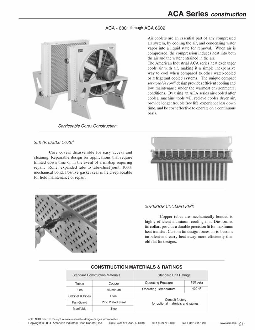
ACA - 6301 through ACA 6602
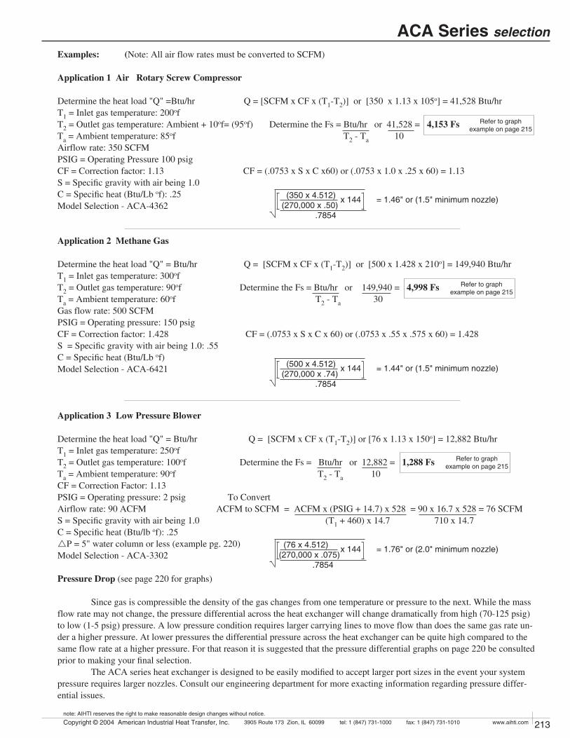
SERVICEABLE CORE®
Core covers disassemble for easy access and cleaning. Repairable design for applications that require limited down time or in the event of a mishap requiring repair. Roller expanded tube to tube-sheet joint. 100% mechanical bond. Positive gasket seal is field replaceable for field maintenance or repair.
SUPERIOR COOLING FINS
Copper tubes are mechanically bonded to highly efficient aluminum cooling fins. Die-formed fin collars provide a durable precision fit for maximum heat transfer. Custom fin design forces air to become turbulent and carry heat away more efficiently than old flat fin designs.
Air coolers are an essential part of any compressed air system, by cooling the air, and condensing water vapor into a liquid state for removal. When air is compressed, the compression induces heat into both the air and the water entrained in the air. The American Industrial ACA series heat exchanger cools air with air, making it a simple inexpensive way to cool when compared to other water-cooled or refrigerant cooled systems. The unique compact serviceable core® design provides efficient cooling and low maintenance under the warmest environmental conditions. By using an ACA series air-cooled after cooler, machine tools will recieve cooler dryer air, provide longer trouble free life, experience less down time, and be cost effective to operate on a continuous basis.
Serviceable Core® Construction
Standard Construction Materials Standard Unit Ratings
Operating Pressure
Operating Temperature
150 psig
400 oF
Consult factory for optional materials and ratings.
Tubes
Fins
Cabinet & Pipes
Fan Guard
Manifolds
Copper
Aluminum
Steel
Zinc Plated Steel
Steel
ACA Series construction
CONSTRUCTION MATERIALS & RATINGS

212 Copyright © 2004 American Industrial Heat Transfer, Inc. tel: 1 (847) 731-10003905 Route 173 Zion, IL 60099 www.aihti.comfax: 1 (847) 731-1010
note: AIHTI reserves the right to make reasonable design changes without notice.
213Copyright © 2004 American Industrial Heat Transfer, Inc. tel: 1 (847) 731-10003905 Route 173 Zion, IL 60099 www.aihti.comfax: 1 (847) 731-1010
note: AIHTI reserves the right to make reasonable design changes without notice.
Compressed Air Normally air compressors have airflow rates based upon the horsepower. Rotary Screw compressors normally discharge air at 180 of - 200 of, prior to after-cooling. Recipro-cating compressors normally discharge air at 250 of - 275 of, prior to after-cooling. Compressors are rated in CFM or cubic feet per minute of free air at inlet conditions. For practical pur-pose we will use sea level at 68 of and 36% relative humidity as a norm. Altitude, differing ambient conditions with respect to temperature and humidity will all affect heat exchanger performance to a degree. Moisture content in air actually increases the Btu/hr load requirement for cooling air by adding an additional condensing load to the gas load requirement. As air rapidly cools, moisture in the compressed air stream will condense and separate into droplets, the more humidity pres-ent the more condensation will occur.
Sizing The performance curves provided are for air. How-ever, gases other than air may be applied to this cooler with respect to compatibility by applying a correction factor. Please take time to check the operating specifications thoroughly for material compatibility, pressure, and size before applying an American Industrial heat exchanger into your system.
TermsApproach Temperature is the desired outlet temperature of the compressed gas minus the inlet ambient air temperature of the external air flowing over the coil. SCFM (Standard Cubic Feet per Minute)A cubic foot of air at 68 of, 14.696 psia, & 36% relative hu-midity, per minute.CFM (Cubic Feet per Minute)Air at inlet atmospheric conditions.ACFM (Actual Cubic Feet per Minute)Air at current pressure, temperature, & humidity conditions without reference to a standard.
To Determine the Heat Load If the heat load (Btu/hr) is unknown a value can be calculated based upon system operational requirements. To properly calculate the heat load (Btu/hr) to be rejected, several items must be known with certainty (see below).• Flow rate SCFM (standard cubic feet pr minute)• Type of gas and its makeup. • System inlet pressure to the heat exchanger.• Ambient temperature where the heat exchanger will be located (hotest condition).• Temperature of the gas at the heat exchanger inlet.• Temperature of the gas desired at heat exchanger outlet.• Maximum acceptable pressure loss or cooled gas.
Using The Chart American Industrial has created a quick reference chart for selecting ACA heat exchangers for Rotary Screw compressors (see page 214) [This chart offers basic infor-mation based upon compressor horsepower and average airflow rates. To properly use the chart, select the compressor horsepower at the left or the air flow rate. Next select the approach to ambient that is desired. Where the two columns intersect is shown the proper ACA model number.]
ACA Series selection
Compressed Air Density @ 140F
0.1
1
0.3 1 10 100Inlet Pressure PSIG
(lbs/
cu.ft
.)
.05200
0.2
0.4
0.6
3 30
x 144 = 2.09" or (2" Nozzle)
x 144
Using The Graphs American Industrial provides performance graphs for ease of model selection. The following calculation examples (page 213), illustrate formulas to determine model selection sizes. It should be noted that there are some assumptions made when applying the basic principles for calculation in the formula. Altitude, humidity, materials, pressures, etc... all contribute to the final selection. Contact American Industrial for more detailed calculation.
Selection The selection process is important, many consider-ations should be made when selecting a heat exchanger. Once the proper Fs requirement is calculated, it is time to apply the data to the graph and make a selection. 1) Find the Flow rate in SCFM located at the bottom of the graph. Follow the graph line up until it matches the calculated Fs from your calculations. If the point falls just above one of the model graphed lines, select the next larger size. If the point is on a line select it as your choice. 2) Check carefully the pressure differential. Units with operat-ing pressures from 70+ psig will have no greater than 2.0 psid within the published flow range. For lower inlet pressure see the pressure drop curves for more detail. 3) Calculate a Nozzle size using the nozzle size calculation to verify your selection has the proper port sizes for your required inlet pressure.
Formula: Nozzle Calculation
Nozzle Size = (SCFM x 4.512) (270,000 x d) .7854
Example:Flow rate = 200 SCFMPressure = 15 psigDensity = (d) from Compressed Air Density Graph
(200 x 4.512) (270,000 x .14) .7854
All numbers in equation are constants except for SCFM and (d) "density".
212 Copyright © 2004 American Industrial Heat Transfer, Inc. tel: 1 (847) 731-10003905 Route 173 Zion, IL 60099 www.aihti.comfax: 1 (847) 731-1010
note: AIHTI reserves the right to make reasonable design changes without notice.
213Copyright © 2004 American Industrial Heat Transfer, Inc. tel: 1 (847) 731-10003905 Route 173 Zion, IL 60099 www.aihti.comfax: 1 (847) 731-1010
note: AIHTI reserves the right to make reasonable design changes without notice.
Examples: (Note: All air flow rates must be converted to SCFM)
Application 1 Air Rotary Screw Compressor
Determine the heat load "Q" =Btu/hr Q = [SCFM x CF x (T1-T2)] or [350 x 1.13 x 105o] = 41,528 Btu/hr T1 = Inlet gas temperature: 200of T2 = Outlet gas temperature: Ambient + 10of= (95of) Determine the Fs = Btu/hr or 41,528 = 4,153 FsTa = Ambient temperature: 85of T2 - Ta 10Airflow rate: 350 SCFMPSIG = Operating Pressure 100 psigCF = Correction factor: 1.13 CF = (.0753 x S x C x60) or (.0753 x 1.0 x .25 x 60) = 1.13 S = Specific gravity with air being 1.0C = Specific heat (Btu/Lb of): .25Model Selection - ACA-4362
Application 2 Methane Gas
Determine the heat load "Q" = Btu/hr Q = [SCFM x CF x (T1-T2)] or [500 x 1.428 x 210o] = 149,940 Btu/hrT1 = Inlet gas temperature: 300ofT2 = Outlet gas temperature: 90of Determine the Fs = Btu/hr or 149,940 = 4,998 FsTa = Ambient temperature: 60of T2 - Ta 30Gas flow rate: 500 SCFMPSIG = Operating pressure: 150 psigCF = Correction factor: 1.428 CF = (.0753 x S x C x 60) or (.0753 x .55 x .575 x 60) = 1.428S = Specific gravity with air being 1.0: .55C = Specific heat (Btu/Lb of)Model Selection - ACA-6421
Application 3 Low Pressure Blower
Determine the heat load "Q" = Btu/hr Q = [SCFM x CF x (T1-T2)] or [76 x 1.13 x 150o] = 12,882 Btu/hrT1 = Inlet gas temperature: 250ofT2 = Outlet gas temperature: 100of Determine the Fs = Btu/hr or 12,882 = 1,288 FsTa = Ambient temperature: 90of T2 - Ta 10CF = Correction Factor: 1.13PSIG = Operating pressure: 2 psig To ConvertAirflow rate: 90 ACFM ACFM to SCFM = ACFM x (PSIG + 14.7) x 528 = 90 x 16.7 x 528 = 76 SCFMS = Specific gravity with air being 1.0 (T1 + 460) x 14.7 710 x 14.7C = Specific heat (Btu/lb of): .25 rP = 5" water column or less (example pg. 220)Model Selection - ACA-3302
Pressure Drop (see page 220 for graphs) Since gas is compressible the density of the gas changes from one temperature or pressure to the next. While the mass flow rate may not change, the pressure differential across the heat exchanger will change dramatically from high (70-125 psig) to low (1-5 psig) pressure. A low pressure condition requires larger carrying lines to move flow than does the same gas rate un-der a higher pressure. At lower pressures the differential pressure across the heat exchanger can be quite high compared to the same flow rate at a higher pressure. For that reason it is suggested that the pressure differential graphs on page 220 be consulted prior to making your final selection. The ACA series heat exchanger is designed to be easily modified to accept larger port sizes in the event your system pressure requires larger nozzles. Consult our engineering department for more exacting information regarding pressure differ-ential issues.
ACA Series selection
x 144 = 1.76" or (2.0" minimum nozzle) (76 x 4.512) (270,000 x .075) .7854
x 144 = 1.44" or (1.5" minimum nozzle) (500 x 4.512) (270,000 x .74) .7854
x 144 = 1.46" or (1.5" minimum nozzle) (350 x 4.512) (270,000 x .50) .7854
Refer to graph example on page 215
Refer to graph example on page 215
Refer to graph example on page 215

214 Copyright © 2004 American Industrial Heat Transfer, Inc. tel: 1 (847) 731-10003905 Route 173 Zion, IL 60099 www.aihti.comfax: 1 (847) 731-1010
note: AIHTI reserves the right to make reasonable design changes without notice.
215Copyright © 2004 American Industrial Heat Transfer, Inc. tel: 1 (847) 731-10003905 Route 173 Zion, IL 60099 www.aihti.comfax: 1 (847) 731-1010
note: AIHTI reserves the right to make reasonable design changes without notice.
ACA Series selection
ROTARY SCREW COMPRESSORS(200OF @125 PSI & 36% relative humidity)
*Approach Temperature the desired outlet temperature of the compressed gas minus the inlet ambient air temperature of the external air flowing over the coil.
T2 - Outlet gas temperature
Ta - Ambient temperature
Example of a model:ACA - 3242 - 3 - __ -____ - ____
Model
Size
Drive TypeNumberof Passes
ACA
ConnectionsBlank = NPTA = ANSI 150#RF Flange
Tubing
1P = 1 pass2P = 2 pass
Coating
N = no motor 1 = single phase 3 = three phase1EXP = single phase3EXP = three phase 5 = 575 Volt
Blank = Enamel (standard)G = Galvanize (cabinet)T = Heresite (core)X = Epoxy (core & cabinet)
Blank = CopperU = 90/10 Cu NiC = Carbon Steel
Using the performance graphs (page 215)
The Flow vs. Fs graph is calculated based upon SCFM units.
To convert volumetric Actual Cubic Feet per Minute (ACFM) into Standard Cubic Feet per Minute (SCFM) see page 213 application 3.
To select a model, locate the flow rate in SCFM located at the bottom of the graph. Proceed upward on the graph until the SCFM flow rate intersects with the calculated
Fs. The curve closest, on or above the intersection point is the proper selection.
Using the one pass graph or two-pass graph depends upon pressure differential, flow, and performance re-quirements. The actual surface area for one or two pass units is the same. However, the airflow velocity in the tubes increases with the number of passes giving slightly higher pressure differentials and better cooling perfor-mance.
CompressorHorse Power
(HP)
Average Air DischargeCubic feet per minute
(SCFM)
Model Size Selection
*Approach Temperature oF (T2 - Ta)
5oF 10oF 15oF 20oF
15 60 ACA - 3302 ACA - 3242 ACA - 3242 ACA - 3182
20 80 ACA - 3302 ACA - 3242 ACA - 3242 ACA - 3182
30 130 ACA - 3362 ACA - 3302 ACA - 3242 ACA - 3242
40 165 ACA - 3362 ACA - 3302 ACA - 3302 ACA - 3242
60 250 ACA - 4362 ACA - 3362 ACA - 3302 ACA - 3302
75 350 ACA - 6362 ACA - 4362 ACA - 3362 ACA - 3302
100 470 ACA - 6362 ACA - 6362 ACA - 3362 ACA - 3362
125 590 ACA - 6422 ACA - 6362 ACA - 4362 ACA - 3362
150 710 ACA - 6422 ACA - 6362 ACA - 6362 ACA - 4362
200 945 ACA - 6482 ACA - 6422 ACA - 6362 ACA - 6362
250 1160 ACA - 6482 ACA - 6422 ACA - 6362 ACA - 6362
300 1450 ACA - 6542 ACA - 6482 ACA - 6422 ACA - 6362
350 1630 ACA - 6542 ACA - 6482 ACA - 6422 ACA - 6362
400 1830 ACA - 6602 ACA - 6482 ACA - 6422 ACA - 6422
500 2150 ACA - 6602 ACA - 6542 ACA - 6482 ACA - 6422

214 Copyright © 2004 American Industrial Heat Transfer, Inc. tel: 1 (847) 731-10003905 Route 173 Zion, IL 60099 www.aihti.comfax: 1 (847) 731-1010
note: AIHTI reserves the right to make reasonable design changes without notice.
215Copyright © 2004 American Industrial Heat Transfer, Inc. tel: 1 (847) 731-10003905 Route 173 Zion, IL 60099 www.aihti.comfax: 1 (847) 731-1010
note: AIHTI reserves the right to make reasonable design changes without notice.
ONE PASS
10
100
1000
10000
1 10 100 1000 8000Flow Rate SCFM
3181
3241
33014301
6481
3361
43616361
6421
6541
6601
Fs
(Btu
/hr
f)
Example App. 2 (pg. 213)
TWO PASS
100
1000
10000
100000
1 10 100 1000 8000Flow Rate SCFM
Fs
(Btu
/hr
f)
3182
3242
3302
4302
6482
33624362
6362
6422
65426602
Example App. 1 (pg. 213)
Example App. 3 (pg. 213)
ACA Series performance
Example
Application #3 (p.5)
SCFM = 76ÐPSI required = 5" H2OModel selection = ACA-6421-3Fs = 1,288 Nozzle check (p.4) = 3.10 or 3"NPT
Fs = Heat Load (Btu/hr)Process exiting temperature (T2) Ambient air entering the cooler (Ta) from cooler

216 Copyright © 2004 American Industrial Heat Transfer, Inc. tel: 1 (847) 731-10003905 Route 173 Zion, IL 60099 www.aihti.comfax: 1 (847) 731-1010
note: AIHTI reserves the right to make reasonable design changes without notice.
217Copyright © 2004 American Industrial Heat Transfer, Inc. tel: 1 (847) 731-10003905 Route 173 Zion, IL 60099 www.aihti.comfax: 1 (847) 731-1010
note: AIHTI reserves the right to make reasonable design changes without notice.
ACA Series dimensions
ACA - 3181 through ACA - 4361
ACA - 6301 through ACA - 6601
MLKJGFNPT
EDCBA
DIMENSIONS (inches)NModel
A
KC
D
AIR FLOW
LL
Fan
ro
tation
F
E
NFan Dia.
GB
M
J
1/2" NPTDRAIN
G
Fan
ro
tation
B
F
NFan Dia.
E
1/2" NPTDRAIN
J
M
D
CK
AIR FLOW
A
L L L
ACA - 3181
ACA - 3241
ACA - 3301
ACA - 4301
ACA - 6301
ACA - 3361
ACA - 4361
ACA - 6361
ACA - 6421
ACA - 6481
ACA - 6541
ACA - 6601
30.6
36.6
42.6
42.6
42.6
48.6
48.6
48.5
54.5
60.6
66.6
72.4
23.0
29.0
35.0
36.0
38.8
41.0
42.0
43.9
50.8
56.8
62.8
67.9
19.8
19.8
19.8
19.8
19.8
19.8
19.8
19.8
27.36
27.36
28.83
30.6
20.25
23.25
26.25
26.25
26.25
29.25
29.25
29.25
32.25
35.25
38.25
41.25
2.5
2.5
2.5
2.5
2.5
2.5
2.5
2.5
2.5
2.5
2.5
2.5
1.5
1.5
2.0
2.5
3.0
2.0
2.5
3.0
4.0
4.0
4.0
4.0
16.3
22.3
28.3
28.3
28.3
34.3
34.4
34.3
40.3
46.3
52.3
58.3
12.98
17.48
21.75
21.55
21.07
26.25
26.05
26.0
29.4
34.1
38.6
43.05
1.5
1.5
1.5
1.5
1.5
1.5
1.5
1.5
2.0
2.0
2.0
2.0
8.38
8.38
8.38
8.38
8.38
8.38
8.38
8.38
6.75
6.75
6.75
6.75
11.93
11.93
12.15
12.35
12.98
12.15
12.35
12.7
13.3
13.3
13.3
13.3
14.0
22.0
28.0
28.0
28.0
32.0
32.0
32.0
36.0
42.0
48.0
48.0

216 Copyright © 2004 American Industrial Heat Transfer, Inc. tel: 1 (847) 731-10003905 Route 173 Zion, IL 60099 www.aihti.comfax: 1 (847) 731-1010
note: AIHTI reserves the right to make reasonable design changes without notice.
217Copyright © 2004 American Industrial Heat Transfer, Inc. tel: 1 (847) 731-10003905 Route 173 Zion, IL 60099 www.aihti.comfax: 1 (847) 731-1010
note: AIHTI reserves the right to make reasonable design changes without notice.
ACA Series dimensions
ACA - 3182 through ACA - 4362
ACA - 6302 through ACA - 6602
Model MLKJGFNPT
EDCBA
DIMENSIONS (inches)
ACA - 3182
ACA - 3242
ACA - 3302
ACA - 4302
ACA - 6302
ACA - 3362
ACA - 4362
ACA - 6362
ACA - 6422
ACA - 6482
ACA - 6542
ACA - 6602
N
A
CLK L
AIR FLOW
D
NFan Dia.
GB
E
J
M
F
Fan
ro
tation
1/2" NPTDRAIN
K
A
L L LC
D
AIR FLOW Fa
nro
tation
B
F
NFan Dia.
E
J
M
G
1/2" NPTDRAIN
30.6
36.6
42.6
42.6
42.6
48.6
48.6
48.5
54.5
60.6
66.6
72.4
23.0
29.0
35.0
36.0
38.8
41.0
42.0
43.9
50.8
56.8
62.8
67.9
19.8
19.8
19.8
19.8
19.8
19.8
19.8
19.8
27.36
27.36
28.83
30.6
20.25
23.25
26.25
26.25
26.25
29.25
29.25
29.25
32.25
35.25
38.25
41.25
2.5
2.5
2.5
2.5
2.5
2.5
2.5
2.5
2.5
2.5
2.5
2.5
1.5
1.5
2.0
2.5
3.0
2.0
2.5
3.0
4.0
4.0
4.0
4.0
16.3
22.3
28.3
28.3
28.3
34.3
34.4
34.3
40.3
46.3
52.3
58.3
12.98
17.48
21.75
21.55
21.07
26.25
26.05
26.0
29.4
34.1
38.6
43.05
1.5
1.5
1.5
1.5
1.5
1.5
1.5
1.5
2.0
2.0
2.0
2.0
8.38
8.38
8.38
8.38
8.38
8.38
8.38
8.38
6.75
6.75
6.75
6.75
11.93
11.93
12.15
12.35
12.98
12.15
12.35
12.7
13.3
13.3
13.3
13.3
14.0
22.0
28.0
28.0
28.0
32.0
32.0
32.0
36.0
42.0
48.0
48.0

1
3
1
3
1
3
1
3
3
3
3
3
3
3
3
3
.25
.25
.25
.25
.5
.5
.5
.5
1.0
1.0
1.0
3.0
5.0
5.0
7.5
10
60-50
60-50
60-50
60-50
60-50
60-50
60-50
60-50
60-50
60-50
60-50
60-50
60-50
60-50
60-50
60-50
115/230 - 90/190
208 - 230/460 - 190/380
115/230 - 90/190
208 - 230/460 - 190/380
115/230 - 90/190
208 - 230/460 - 190/380
115/230 - 90/190
208 - 230/460 - 190/380
208 - 230/460 - 190/380
208 - 230/460 - 190/380
208 - 230/460 - 190/380
208 - 230/460 - 190/380
208 - 230/460 - 190/380
208 - 230/460 - 190/380
208 - 230/460 - 190/380
208 - 230/460 - 190/380
ACA- 3181/2- 1
ACA- 3181/2 -3
ACA- 3241/2 -1
ACA- 3241/2 -3
ACA- 3301/2 -1
ACA- 3301/2 -3
ACA- 4301/2 -1
ACA- 4301/2 -3
ACA- 6301/2 -3
ACA- 3361/2 -3
ACA- 4361/2- 3
ACA- 6361/2 -3
ACA- 6421/2 -3
ACA- 6481/2 -3
ACA- 6541/2 -3
ACA- 6601/2 -3
3.2/1.6/2.8-1.4
1.3/.65/1.1-.55
6.8/3.1-3.4
1.7/2.0/1.0
9.6/4.7-4.8/10.4/5.2
2.4-2.7/1.35-2.5/1.25
9.6/4.7-4.8/10.4/5.2
2.4-2.7/1.35-2.5/1.25
4/2-3.7/1.85
4/2-3.7/1.85
4/2-3.7/1.85
8.4-6.8/3.4
8.2-7.6/3.8
14.0/7.0
20.4/10.2
28.0/14.0
TEFC
TEFC
TEFC
TEFC
TEFC
TEFC
TEFC
TEFC
TEFC
TEFC
TEFC
TEFC
TEFC
TEFC
TEFC
TEFC
48
48
56
56
56
56
56
56
56
56
56
182T
213T
213T
254T
256T
1725-1440
1725-1440
1140-950
1140-950
1140-950
1140-950
1140-950
1140-950
1140-950
1140-950
1140-950
1725-1440
1140-950
1140-950
1140-950
1140-950
1.15
1.15
1.15
1.15
1.15
1.15
1.15
1.15
1.15
1.15
1.15
1.15
1.15
1.15
1.15
1.15
NO
NO
NO
NO
NO
NO
NO
NO
NO
NO
NO
NO
NO
NO
NO
NO
.25
.25
.33
.33
.75
.75
.75
.75
1.0
1.0
1.0
3
5
5
7.5
10
1
3
1
3
1
3
1
3
3
3
3
3
3
3
3
3
60
60
60
60
60
60
60
60
60
60
60
60
60
60
60
60
1725
1725
1140
1140
1140
1140
1140
1140
1140
1140
1140
1725
1160
1160
1160
1160
115/230
208-230/460
115/230
208-230/460
115/230
208-230/460
115/230
208-230/460
230/460
230/460
230/460
230/460
230/460
230/460
230/460
230/460
48
48
56
56
56
56
56
56
56
56
56
182
215
215
256
256
EXP
EXP
EXP
EXP
EXP
EXP
EXP
EXP
EXP
EXP
EXP
EXP
EXP
EXP
EXP
EXP
5.8/2.8
1.4-1.3/.65
7.8/3.5
1.18-1.6/8
9.4/4.8
2.5-2.4/1.2
9.4/4.8
2.5-2.4/1.2
3.8/1.9
3.8/1.9
3.8/1.9
8.8/4.4
15.0-13.8/6.9
15.0-13.8/6.9
21.6-20.4/10.2
29-26/13
YES
YES
YES
YES
YES
YES
YES
YES
YES
YES
YES
YES
YES
YES
YES
YES
1.0
1.0
1.0
1.0
1.0
1.0
1.0
1.0
1.0
1.0
1.15
1.15
1.15
1.15
1.15
1.15
ACA- 3181/2 -1
ACA- 3181/2 -3
ACA- 3241/2 -3
ACA- 3241/2 -1
ACA- 3301/2 -3
ACA- 3301/2 -1
ACA- 4301/2 -3
ACA- 4301/2 -1
ACA- 6301/2 -1
ACA- 3361/2 -3
ACA- 4361/2 -3
ACA- 6361/2 -3
ACA- 6421/2 -3
ACA- 6481/2 -3
ACA- 6541/2 -3
ACA- 6601/2 -3
218 Copyright © 2004 American Industrial Heat Transfer, Inc. tel: 1 (847) 731-10003905 Route 173 Zion, IL 60099 www.aihti.comfax: 1 (847) 731-1010
note: AIHTI reserves the right to make reasonable design changes without notice.
219Copyright © 2004 American Industrial Heat Transfer, Inc. tel: 1 (847) 731-10003905 Route 173 Zion, IL 60099 www.aihti.comfax: 1 (847) 731-1010
note: AIHTI reserves the right to make reasonable design changes without notice.
ACA Series motor data
NOTE: Basic electric drive units are supplied with one of the corresponding above listed motors.
1) Motor electrical ratings are an approximate guide and may vary between motor manufacturers. Consult ratings on motor data plate prior to installation and operation.
2) Explosion proof, high temperature, severe duty, chemical, IEC, Canadian Standards Association, and Underwriters Laboratory recognized motors are available upon request.
3) American Industrial reserves the right to enact changes to motor brand, type and ratings regarding horsepower, RPM,FLA,and service factor for standard products without no-tice. All specific requirements will be honored without change.
4) Fan rotation is clockwise when facing the motor shaft.
5) The above motors contain factory lubricated shielded ball bearings (no additional lubrication is required).
6) Abbreviation Index TEFC...........................Totally Enclosed, Fan Cooled EXP.............................Explosion Proof
ELECTRIC MOTOR NOTES:
CLASS I,DIV.1, GROUP D or CLASS II,DIV.2, GROUP F & G EXPLOSION PROOF MOTOR DATAThermalOverload
Service FactorRPMHzPhase Volts Full Load
AmperesHorsePowerModel NEMA
FrameEnclosure
Type
ELECTRIC MOTOR DATAThermalOverload
Service FactorRPMHzPhase Volts Full Load
AmperesHorsePowerModel NEMA
FrameEnclosure
Type
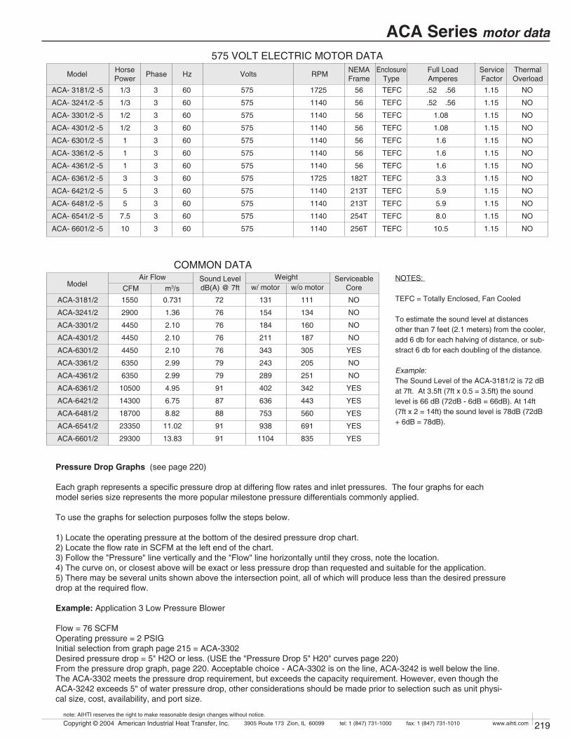
1550
2900
4450
4450
4450
6350
6350
10500
14300
18700
23350
29300
0.731
1.36
2.10
2.10
2.10
2.99
2.99
4.95
6.75
8.82
11.02
13.83
NO
NO
NO
NO
YES
NO
NO
YES
YES
YES
YES
YES
72
76
76
76
76
79
79
91
87
88
91
91
111
134
160
187
305
205
251
342
443
560
691
835
131
154
184
211
343
243
289
402
636
753
938
1104
218 Copyright © 2004 American Industrial Heat Transfer, Inc. tel: 1 (847) 731-10003905 Route 173 Zion, IL 60099 www.aihti.comfax: 1 (847) 731-1010
note: AIHTI reserves the right to make reasonable design changes without notice.
219Copyright © 2004 American Industrial Heat Transfer, Inc. tel: 1 (847) 731-10003905 Route 173 Zion, IL 60099 www.aihti.comfax: 1 (847) 731-1010
note: AIHTI reserves the right to make reasonable design changes without notice.
ACA Series motor data
COMMON DATASound LeveldB(A) @ 7ft
Air FlowCFM m3/sModel
ServiceableCore
NOTES:
TEFC = Totally Enclosed, Fan Cooled
To estimate the sound level at distances other than 7 feet (2.1 meters) from the cooler, add 6 db for each halving of distance, or sub-stract 6 db for each doubling of the distance.
Example:The Sound Level of the ACA-3181/2 is 72 dB at 7ft. At 3.5ft (7ft x 0.5 = 3.5ft) the sound level is 66 dB (72dB - 6dB = 66dB). At 14ft (7ft x 2 = 14ft) the sound level is 78dB (72dB + 6dB = 78dB).
ACA-3181/2
ACA-3241/2
ACA-3301/2
ACA-4301/2
ACA-6301/2
ACA-3361/2
ACA-4361/2
ACA-6361/2
ACA-6421/2
ACA-6481/2
ACA-6541/2
ACA-6601/2
Weight
575 VOLT ELECTRIC MOTOR DATAThermalOverload
Service FactorRPMHzPhase Volts Full Load
AmperesHorsePowerModel NEMA
FrameEnclosure
TypeACA- 3181/2 -5
ACA- 3241/2 -5
ACA- 3301/2 -5
ACA- 4301/2 -5
ACA- 6301/2 -5
ACA- 3361/2 -5
ACA- 4361/2 -5
ACA- 6361/2 -5
ACA- 6421/2 -5
ACA- 6481/2 -5
ACA- 6541/2 -5
ACA- 6601/2 -5
1/3
1/3
1/2
1/2
1
1
1
3
5
5
7.5
10
3
3
3
3
3
3
3
3
3
3
3
3
60
60
60
60
60
60
60
60
60
60
60
60
575
575
575
575
575
575
575
575
575
575
575
575
1725
1140
1140
1140
1140
1140
1140
1725
1140
1140
1140
1140
56
56
56
56
56
56
56
182T
213T
213T
254T
256T
.52 .56
.52 .56
1.08
1.08
1.6
1.6
1.6
3.3
5.9
5.9
8.0
10.5
1.15
1.15
1.15
1.15
1.15
1.15
1.15
1.15
1.15
1.15
1.15
1.15
TEFC
TEFC
TEFC
TEFC
TEFC
TEFC
TEFC
TEFC
TEFC
TEFC
TEFC
TEFC
w/ motor w/o motor
Pressure Drop Graphs (see page 220)
Each graph represents a specific pressure drop at differing flow rates and inlet pressures. The four graphs for each model series size represents the more popular milestone pressure differentials commonly applied.
To use the graphs for selection purposes follw the steps below.
1) Locate the operating pressure at the bottom of the desired pressure drop chart.2) Locate the flow rate in SCFM at the left end of the chart.3) Follow the "Pressure" line vertically and the "Flow" line horizontally until they cross, note the location.4) The curve on, or closest above will be exact or less pressure drop than requested and suitable for the application.5) There may be several units shown above the intersection point, all of which will produce less than the desired pressure drop at the required flow.
Example: Application 3 Low Pressure Blower
Flow = 76 SCFMOperating pressure = 2 PSIGInitial selection from graph page 215 = ACA-3302Desired pressure drop = 5" H2O or less. (USE the "Pressure Drop 5" H20" curves page 220)From the pressure drop graph, page 220. Acceptable choice - ACA-3302 is on the line, ACA-3242 is well below the line. The ACA-3302 meets the pressure drop requirement, but exceeds the capacity requirement. However, even though the ACA-3242 exceeds 5" of water pressure drop, other considerations should be made prior to selection such as unit physi-cal size, cost, availability, and port size.
NO
NO
NO
NO
NO
NO
NO
NO
NO
NO
NO
NO

220 Copyright © 2004 American Industrial Heat Transfer, Inc. tel: 1 (847) 731-10003905 Route 173 Zion, IL 60099 www.aihti.comfax: 1 (847) 731-1010
note: AIHTI reserves the right to make reasonable design changes without notice.
221Copyright © 2004 American Industrial Heat Transfer, Inc. tel: 1 (847) 731-10003905 Route 173 Zion, IL 60099 www.aihti.comfax: 1 (847) 731-1010
note: AIHTI reserves the right to make reasonable design changes without notice.
ACA Series pressure drop graphs
0 25 50 75 100 125 1500
100
200
300
400
500
600
700
800
900
1000
1100
1200
1300
1400
1500
a
b
c
d
e
a - 6421, 6481, 6541, 6601b - 6361c - 4301, 4361d - 3301, 3361e - 3181, 3241
Pressure Drop 0.5 PSI
0
100
200
300
400
0 1 2 3 4 5 6 7 8 9 10 11
a
b
c
d
e
a - 6421, 6481, 6541, 6601b - 6361c - 4301, 4361d - 3301, 3361e - 3181, 3241
Pressure Drop 5" H20
0
100
200
300
0 1 2 3 4 5 6 7 8 9 10 11
abc
d
e
f
g
a - 6602b - 6482, 6542c - 6422d - 6362
g - 3182, 3242f - 3302, 3362e - 4302, 4362
Application 3 example pg. 213
Pressure Drop 5" H20
0
100
200
300
400
500
600
700
800
900
1000
1100
0 25 50 75 100 125 150
abc
d
a - 6602b - 6482, 6542c - 6422d - 6362e - 4302, 4362f - 3302, 3362g - 3182, 3242
e
f
g
Pressure Drop 0.5 PSI
0 25 50 75 100 125 1500
200
400
600
800
1000
1200
1400
1600
1800
2000
2200
a
b
c
d
e
a - 6421, 6481, 6541, 6601b - 6361c - 4301, 4361d - 3301, 3361e - 3181, 3241
0
200
400
600
800
1000
1200
1400
1600
0 25 50 75 100 125 150
a
c
d
e
f
g
b
a - 6602b - 6482, 6542c - 6422d - 6362e - 4302, 4362f - 3302, 3362g - 3182, 3242
Pressure Drop 1.0 PSI Pressure Drop 1.0 PSI
0
500
1000
1500
2000
2500
3000
0 25 50 75 100 125 150
a
b
c
d
e
a - 6421, 6481, 6541, 6601b - 6361c - 4301, 4361d - 3301, 3361e - 3181, 3241
0
500
1000
1500
2000
2500
0 25 50 75 100 125 150
abc
d
e
f
g
a - 6602b - 6482, 6542c - 6422d - 6362e - 4302, 4362f - 3302, 3362g - 3182, 3242
Pressure Drop 2.0 PSI Pressure Drop 2.0 PSI
Flow
Rat
e (S
CFM
)
Inlet Pressure (PSIG)
Flow
Rat
e (S
CFM
)Fl
ow R
ate
(SC
FM)
Flow
Rat
e (S
CFM
)Fl
ow R
ate
(SC
FM)
Inlet Pressure (PSIG)
Inlet Pressure (PSIG)
Inlet Pressure (PSIG)
Inlet Pressure (PSIG)
Inlet Pressure (PSIG)
Flow
Rat
e (S
CFM
)Fl
ow R
ate
(SC
FM)
Inlet Pressure (PSIG)
Inlet Pressure (PSIG)
Flow
Rat
e (S
CFM
)

220 Copyright © 2004 American Industrial Heat Transfer, Inc. tel: 1 (847) 731-10003905 Route 173 Zion, IL 60099 www.aihti.comfax: 1 (847) 731-1010
note: AIHTI reserves the right to make reasonable design changes without notice.
221Copyright © 2004 American Industrial Heat Transfer, Inc. tel: 1 (847) 731-10003905 Route 173 Zion, IL 60099 www.aihti.comfax: 1 (847) 731-1010
note: AIHTI reserves the right to make reasonable design changes without notice.
ACA Series installation & maintenance
Receiving:a) Inspect unit for any shipping damage before uncrating. Indicate all damages to the trucking firms' delivery person and mark it on the receiving bill before accepting the freight. Make sure that the core and fan are not damaged. Rotate the fan blade to make sure that it moves freely. The published weight information located in this brochure is approximate. True shipment weights are deter-mined at the time of shipping and may vary. Approximate weight information published herein is for engineering approximation purposes and should not be used for exact shipping weight. Since the warranty is based upon the unit date code located on the model identification tag, removal or manipulation of the identi-fication tag will void the manufacturers warranty.
b) When handling the ACA heat exchanger, special care should be taken to avoid damage to the core and fan. All units are shipped with wood skids for easy forklift handling
c) Standard Enamel Coating: American Industrial provides its standard products with a normal base coat of oil base air cure enamel paint. The enamel paint is applied as a temporary protec-tive and esthetic coating prior to shipment. While the standard enamel coating is durable, American Industrial does not war-rantee it as a long-term finish coating. It is strongly suggested that a more durable final coating be applied after installation or prior to long-term storage in a corrosive environment to cover any accidental scratches, enhance esthetics, and further prevent corrosion. It is the responsibility of the customer to provide regular maintenance against chips, scratches, etc... and regular touch up maintenance must be provided for long-term benefits and corrosion prevention.
Installation:a) American Industrial recommends that the equipment supplied should be installed by qualified personal who have solid under-standing of system design, pressure and temperature ratings, and piping assembly. Verify the service conditions of the system prior to applying any ACA series cooler. If the system pressure or temperature does not fall within the parameters on ACA rat-
ing tag located on the heat exchanger, contact our factory prior to installation or operation.
b) In order for the heat exchanger to properly function, installa-tion should be made with minimum airflow obstruction distance of not less than twenty (20) inches on both fan intake and exiting side of the heat exchanger.
c) Process piping should be as indicated above with the process flow entering into the upper port and exiting out the lower port (see illustration). This configuration will allow for condensate moisture to drain completely from the equipment. It is recom-mended that an air separator or automatic drip leg be applied to the outlet side of the heat exchanger to trap any moisture that develops.
d) Flow line sizes should be sized to handle the appropriate flow to meet the system pressure drop requirements. If the nozzle size of the heat exchanger is smaller than the process line size an in-creased pressure differential at the heat exchanger may occur.
e) ACA series coolers are produced with both brazed ACA-3181 through ACA-4362, and serviceable core® ACA-6301 through ACA-6602 style coils. A brazed construction coil does not allow internal tube access. A serviceable core® will allow full accessi-bility to the internal tubes for cleaning and maintenance. ACA series coolers are rated for 150 PSIG working pressure, and a 400of working temperature.
f) Special Coatings: American Industrial offers as customer op-tions, Air-Dry Epoxy, and Heresite (Air-Dry Phenolic) coatings at additional cost. American Industrial offers special coatings upon request, however American Industrial does not warrantee coatings to be a permanent solution for any equipment against corrosion. It is the responsibility of the customer to provide regular maintenance against chips, scratches, etc... and regular touch up maintenance must be provided for long-term benefits and corrosion prevention.
PIPING HOOK UP
TWO PASS
Fan
rotationINLET
OUTLET
ONE PASS
Fan
ro
tationINLET
OUTLET
Condensate Drain
Condensate Drain
222 Copyright © 2004 American Industrial Heat Transfer, Inc. tel: 1 (847) 731-10003905 Route 173 Zion, IL 60099 www.aihti.comfax: 1 (847) 731-1010
note: AIHTI reserves the right to make reasonable design changes without notice.
223Copyright © 2004 American Industrial Heat Transfer, Inc. tel: 1 (847) 731-10003905 Route 173 Zion, IL 60099 www.aihti.comfax: 1 (847) 731-1010
note: AIHTI reserves the right to make reasonable design changes without notice.
g) Electric motors should be connected only to supply source of the same characteristics as indicated on the electric motor information plate. Prior to starting, verify that the motor and fan spin freely without obstruction. Check carefully that the fan turns in the correct rotation direction normally counter clockwise from the motor side (fan direction arrow). Failure to operate the fan in the proper direction could reduce performance or cause serious damage to the heat exchanger or other components. Fan blades should be rechecked for tightness after the first 100 hours of operation.
MaintenanceRegular maintenance intervals based upon the surrounding and operational conditions should be maintained to verify equipment performance and to prevent premature component failure. Since some of the components such as, motors, fans, load adapters, etc... are not manufactured by American Industrial maintenance requirements provided by the manufacture must be followed.
a) Inspect the entire heat exchanger and motor/fan assembly for loosened bolts, loose connections, broken components, rust spots, corrosion, fin/coil clogging, or external leakage. Make immediate repairs to all affected areas prior to restarting and operating the heat exchanger or its components.
b) Heat exchangers operating in oily or dusty environments will often need to have the coil cooling fins cleaned. Oily or clogged fins should be cleaned by carefully brushing the fins and tubes with water or a non-aggressive degreasing agent mixture (Note: Cleaning agents that are not compatible with copper, brass, aluminum, steel or stainless steel should not be used). A compressed air or a water stream can be used to dislodge dirt and clean the coil further. Any external dirt or oil on the electric motor and fan assembly should be removed. Caution: Be sure to disconnect the electric motor from its power source prior to doing any maintenance.
c) In most cases it is not necessary to internally flush the coil. In circumstances where the coil has become plugged or has a substantial buildup of material, flushing the coil with water or a solvent may be done. Flushing solvents should be non-ag-gressive suitable for the materials of construction. Serviceable Core® models can be disassembled and inspected or cleaned if required.
d) Most low horsepower electric motors do not require any ad-ditional lubrication. However, larger motors must be lubricated with good quality grease as specified by the manufacture at least once every 6-9 months or as directed by the manufacture. T.E.F.C. air ventilation slots should be inspected and cleaned regularly to prevent clogging and starving the motor of cooling air. To maintain the electric motor properly see the manufactures requirements and specifications.
e) Fan blades should be cleaned and inspected for tightness dur-ing the regular maintenance schedule when handling a fan blade care must be given to avoid bending or striking any of the blades. Fan blades are factory balanced and will not operate properly if damaged or unbalanced. Damaged fan blades can cause exces-sive vibration and severe damage to the heat exchanger or drive motor.
Replace any damaged fan with an American industrial suggested replacement.
f) ACA heat exchanger cabinets are constructed using 7ga. through 18ga. steel that may be bent back into position if dam-aged. Parts that are not repairable can be purchased through American Industrial.
g) Coil fins that become flattened can be combed back into position. This process may require removal of the coil from the cabinet.
h) It is not advisable to attempt repairs to brazed joints of a brazed construction coil unless it will be done by an expert in silver sol-der brazing. Brazed coils are heated uniformly during the original manufacturing process to prevent weak zones from occurring. Uncontrolled reheating of the coil may result in weakening of the tube joints surrounding the repair area. In many instances brazed units that are repaired will not hold up as well to the rigors of the system as will a new coil. American Industrial will not warranty or be responsible for any repairs done by unauthorized sources. Manipulation in any way other than normal application will void the manufactures warranty.
i) Units containing a Serviceable Core® have bolted manifold covers that can be removed for cleaning or repair purposes.
Servicing SequenceAmerican Industrial has gone to great lengths to provide com-ponents that are repairable. If the ACA unit requires internal cleaning or attention the following steps will explain what must be done to access the internal tubes. Be sure to order gasket kits or repair parts prior to removal and disassembly to minimize down time.
a) To clean the internal tubes first remove all connection pipes from the unit.
b) Be sure the unit is drained of all water etc...
c) Place the ACA unit in an area that it can be accessed from all sides.
d) Remove the manifold cover bolts and hardware and place them into a secure place.
e) The manifold covers are tightly compressed and may need some prying to separate them from the gasket, physically remove the cover assemblies from both sides.
f) The tubes are now accessible for cleaning. We suggest a mild water-soluble degreaser be used with a brush. Tubing I.D. is .325 a plastic bristle brush on a rod will work best for cleaning the tubes. Steel brushes should be avoided since the steel is harder than the copper tubing and may heavily score the tubes if used.
g) If there are any leaking tubes you may plug them be forcing a soft metal plug into the hole and tapping it tight. You may in some cases weld the leaking tube shut however, care should be taken since excessive heat may cause surrounding tube joints to loosen and leak.
ACA Series installation & maintenance

144 Copyright © 2004 American Industrial Heat Transfer, Inc. tel: 1 (847) 731-10003905 Route 173 Zion, IL 60099 www.aihti.comfax: 1 (847) 731-1010
note: AIHTI reserves the right to make reasonable design changes without notice.
145Copyright © 2004 American Industrial Heat Transfer, Inc. tel: 1 (847) 731-10003905 Route 173 Zion, IL 60099 www.aihti.comfax: 1 (847) 731-1010
note: AIHTI reserves the right to make reasonable design changes without notice.
AIR COOLED
OIL COOLERS
AOCH - AOCHM SERIES
• Thermal capacity to 210hp (157Kw).
• Severe duty construction with OSHA
guard.
• Serviceable Core®.
• Operating temperature of 300°F at 300 PSI.
• Electric or hydraulic drive.
• Optional: internal built-in bypass relief valve.
• Can be customized to fit your needs.
• Cools: Fluid power systems, rock crushers,
presses, shears, lubrication equipment for
paper machinery, gear drives, marine transmis-
sions, etc.
AOCHM SERIES with hydraulic motor
AOCH SERIES with electric motor
®

146 Copyright © 2004 American Industrial Heat Transfer, Inc. tel: 1 (847) 731-10003905 Route 173 Zion, IL 60099 www.aihti.comfax: 1 (847) 731-1010
note: AIHTI reserves the right to make reasonable design changes without notice.
147Copyright © 2004 American Industrial Heat Transfer, Inc. tel: 1 (847) 731-10003905 Route 173 Zion, IL 60099 www.aihti.comfax: 1 (847) 731-1010
note: AIHTI reserves the right to make reasonable design changes without notice.
AOCH & AOCHM Series overview
AOCH SERIES with electric drive Industrial air-cooled oil coolers, high performance six row rolled or brazed tube industrial series heat exchangers with direct electric drive cooling fan, OSHA guard, and air directing louvers. Rated operating temperature of 400oF at 300 PSIG. Services standard flow rates from 4 to 250 GPM. Thermal capacity up to 210 hp (157Kw). NPT, flange, or SAE straight thread port connections. Optional built-in bypass relief valve 30 PSI or 65 PSI. Can be modified to meet your requirements. Suitable for most hydraulic oils, lubrications oils, synthetic com-pressor oils, ethylene glycol, and many other fluids compatible with listed material.
AOCHM SERIES with hydraulic drive Industrial air-cooled oil coolers with hydraulic fan drive, high performance six row rolled or brazed tube industrial series heat exchangers with direct electric drive cooling fan, OSHA guard, and air directing louvers. Rated operating temperature of 400oF at 300 PSIG. Services standard flow rates from 4 to 250 GPM. Thermal capacity up to 210 hp (157Kw). NPT, flange, or SAE straight thread port connections. Optional built-in bypass relief valve 30 PSI or 65 PSI. Can be modified to meet your requirements. Suitable for most hydraulic oils, lubrications oils, synthetic compressor oils, ethylene glycol, and many other fluids compatible with listed material.
AOCH & AOCHM SERIES with optional screen Same rugged features as standard AOCH & AOCHM
Series with fabricated steel front screen in place of lou-
vers.
AOCS Series WITH ELECTRIC DRIVE
Severe duty air-cooled oil coolers, super capacity, rolled tube industrial series heat exchangers with direct electric drive cooling fan, OSHA guard, and heavy duty front screen. Rated operating temperature of 300oF at 200 PSIG. Standard flow rates from 10 to 600 GPM. NPT, ANSI flange, or SAE code 61 four bolt flange port connections. Optional built-in bypass relief valve 30 PSI or 65 PSI. Can be modified to meet your requirements. Suitable for most hydraulic oils, lubrications oils, synthetic compressor oils, ethylene glycol, and many other fluids compatible with listed material.
For larger cooling capacity (see page 157)
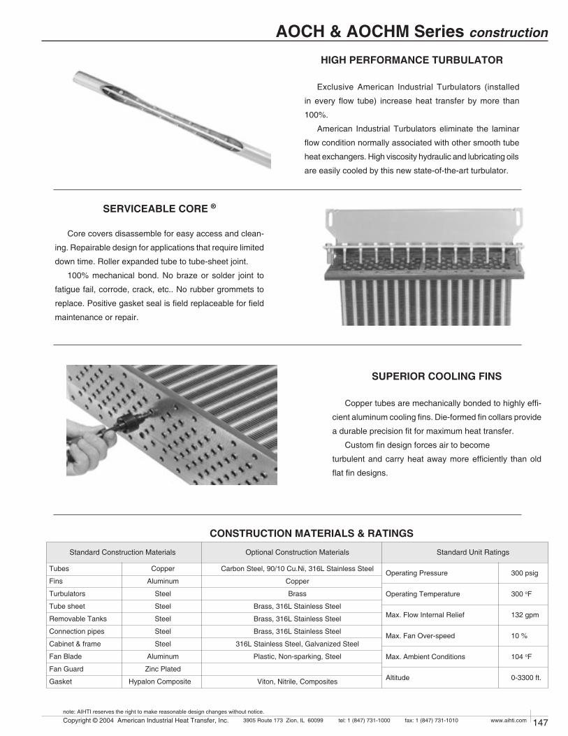
146 Copyright © 2004 American Industrial Heat Transfer, Inc. tel: 1 (847) 731-10003905 Route 173 Zion, IL 60099 www.aihti.comfax: 1 (847) 731-1010
note: AIHTI reserves the right to make reasonable design changes without notice.
147Copyright © 2004 American Industrial Heat Transfer, Inc. tel: 1 (847) 731-10003905 Route 173 Zion, IL 60099 www.aihti.comfax: 1 (847) 731-1010
note: AIHTI reserves the right to make reasonable design changes without notice.
AOCH & AOCHM Series construction
SERVICEABLE CORE ®
Core covers disassemble for easy access and clean-
ing. Repairable design for applications that require limited
down time. Roller expanded tube to tube-sheet joint.
100% mechanical bond. No braze or solder joint to
fatigue fail, corrode, crack, etc.. No rubber grommets to
replace. Positive gasket seal is field replaceable for field
maintenance or repair.
SUPERIOR COOLING FINS
Copper tubes are mechanically bonded to highly effi-
cient aluminum cooling fins. Die-formed fin collars provide
a durable precision fit for maximum heat transfer.
Custom fin design forces air to become
turbulent and carry heat away more efficiently than old
flat fin designs.
CONSTRUCTION MATERIALS & RATINGS
Tubes Copper
Fins Aluminum
Turbulators Steel
Tube sheet Steel
Removable Tanks Steel
Connection pipes Steel
Cabinet & frame Steel
Fan Blade Aluminum
Fan Guard Zinc Plated
Gasket Hypalon Composite
Operating Pressure 300 psig
Operating Temperature 300 oF
Max. Flow Internal Relief 132 gpm
Max. Fan Over-speed 10 %
Max. Ambient Conditions 104 oF
Altitude 0-3300 ft.
Carbon Steel, 90/10 Cu.Ni, 316L Stainless Steel
Copper
Brass
Brass, 316L Stainless Steel
Brass, 316L Stainless Steel
Brass, 316L Stainless Steel
316L Stainless Steel, Galvanized Steel
Plastic, Non-sparking, Steel
Viton, Nitrile, Composites
Standard Construction Materials Optional Construction Materials Standard Unit Ratings
HIGH PERFORMANCE TURBULATOR Exclusive American Industrial Turbulators (installed
in every flow tube) increase heat transfer by more than
100%.
American Industrial Turbulators eliminate the laminar
flow condition normally associated with other smooth tube
heat exchangers. High viscosity hydraulic and lubricating oils
are easily cooled by this new state-of-the-art turbulator.
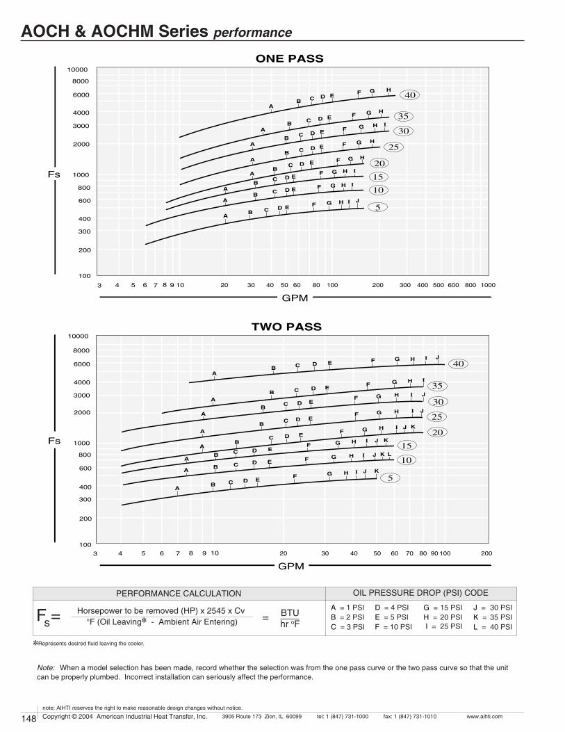
148 Copyright © 2004 American Industrial Heat Transfer, Inc. tel: 1 (847) 731-10003905 Route 173 Zion, IL 60099 www.aihti.comfax: 1 (847) 731-1010
note: AIHTI reserves the right to make reasonable design changes without notice.
149Copyright © 2004 American Industrial Heat Transfer, Inc. tel: 1 (847) 731-10003905 Route 173 Zion, IL 60099 www.aihti.comfax: 1 (847) 731-1010
note: AIHTI reserves the right to make reasonable design changes without notice.
AOCH & AOCHM Series performance
Horsepower to be removed (HP) x 2545 x Cv °F (Oil Leaving] - Ambient Air Entering) Fs =
OIL PRESSURE DROP (PSI) CODE
BTUhr oF
=
PERFORMANCE CALCULATION
]Represents desired fluid leaving the cooler.
D = 4 PSIE = 5 PSIF = 10 PSI
G = 15 PSIH = 20 PSI I = 25 PSI
J = 30 PSIK = 35 PSIL = 40 PSI
A = 1 PSIB = 2 PSIC = 3 PSI
5
10
15
20
25
30
35
40
800
600
400
300
100
200
3 4 5 6 7 8 9 10 20 30 40 50 60 80 100 200 300 400 500 600 800 1000
1000
8000
6000
4000
3000
2000
10000
ONE PASS
GPM
Fs
B
B
A
A
C
C
D
D
E
E
F
F
G
G
H
H
I
I
J
BA
C D EF G H IB
A
C D E F G H
BA
C D EF G H
BA
C D E F G H
I
BA
C D E F G HBA
C D E F G H
5
10
15
20
25
30
35
40
800
600
400
300
100
200
3 4 5 6 7 8 9 10 20 30 40 50 60 80 9070 100 200
1000
8000
6000
4000
3000
2000
10000TWO PASS
GPM
Fs
B
B
A
A
C
C
D
D
E
E
F
F
G
G
H
H J K L
I
I
J K
BA
C D EF G H J KI
J KI
JI
BA
C D EF G H
BA
C D E F G H
BA
C D EF G H
I
I
BA
C D EF G H J
I J
BA
C D EF G H
Note: When a model selection has been made, record whether the selection was from the one pass curve or the two pass curve so that the unit can be properly plumbed. Incorrect installation can seriously affect the performance.
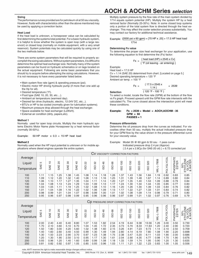
148 Copyright © 2004 American Industrial Heat Transfer, Inc. tel: 1 (847) 731-10003905 Route 173 Zion, IL 60099 www.aihti.comfax: 1 (847) 731-1010
note: AIHTI reserves the right to make reasonable design changes without notice.
149Copyright © 2004 American Industrial Heat Transfer, Inc. tel: 1 (847) 731-10003905 Route 173 Zion, IL 60099 www.aihti.comfax: 1 (847) 731-1010
note: AIHTI reserves the right to make reasonable design changes without notice.
AOCH & AOCHM Series selection
SizingThe performance curves provided are for petroleum oil at 50 ssu viscosity. However, fluids with characteristics other than the above mentioned may be used by applying a correction factor.
Heat LoadIf the heat load is unknown, a horsepower value can be calculated by first determining the systems total potential. For a basic hydraulic system, it is helpful to know whether the system is open loop (with a large res-ervoir) or closed loop (normally on mobile equipment, with a very small reservoir). System potentials may be calculated quickly by using one of the two methods below.
There are some system parameters that will be required to properly ac-complish the sizing calculations. Without system parameters, it is difficult to determine the optimal heat exchanger size. Normally many of the system parameters can be found on hydraulic schematics or on tags located on the actual equipment. Following are some basic parameters that you should try to acquire before attempting the sizing calculations. However, it is not necessary to have every parameter listed below.
• Main system flow rate (gpm) & operating pressure (psi). • Electric motor HP driving hydraulic pump (if more than one add up
the Hp for all). • Desired temperature (°F). • Fluid type (SAE 10, 20, 30, etc....). • Ambient air temperature (warmest day). • Desired fan drive (hydraulic, electric, 12-24V DC, etc...). • BTU's or HP to be cooled (normally given for lubrication systems). • Maximum pressure drop allowed through the heat exchanger. • Space available for heat exchanger (LxWxH). • External air condition (dirty, papers,etc).
Method 1Normally used for open loop circuits. Multiply the main hydraulic sys-tems Electric Motor Name plate Horsepower by a heat removal factor (normally 30-50%).
Example: 50 HP motor x 0.3 = 15 HP heat load
Method 2Normally used when the HP input potential is unknown or for mobile ap-plications where diesel engines operate the entire system.
Multiply system pressure by the flow rate of the main system divided by 1714 equals system potential (HP). Multiply the system HP by a heat removal factor (Normally 25-35%). Note: In some closed loop systems only a portion of the total system flow is directed through the heat ex-changer. This may affect the cooler selection process substantially. You may contact our factory for additional technical assistance.
Example:
Determining Fs valueTo determine the proper size heat exchanger for your application, use the following equation to first determine the (Fs) factor:
Fs =
Example: Heat load = 17.5 HP Cv = 1.14 (SAE 20) determined from chart. [Located on page 5.] Desired operating temperature = 120 °FAmbient air temp. = 100 °F
Fs = = 2539
SelectionTo select a model, locate the flow rate (GPM) at the bottom of the flow vs Fs graph. Proceed upward until the GPM flow rate intersects with the calculated Fs. The curve closest above the intersection point will meet these conditions.
Example: Fs = 2539 = Model = AOCH,AOCHM - 35 GPM = 60 PASSES = 1
Pressure differentialsDetermine the oil pressure drop from the curves as indicated. For vis-cosities other than 50 ssu, multiply the actual indicated pressure drop for your GPM flow by the value shown in the pressure differential curve for your viscosity value.
Example: Model 35 @ 60 gpm & 50 ssu -1 pass curve- Indicated pressure drop 2.4 psi (Approx) { 2.4 psi x 2.8Cp (for SAE-20 oil) } = 6.72 corrected psi
(2000 psi x 60 gpm) = [70 HP x .25] = 17.5 HP heat load _______________ 1714
{ heat load (HP) x 2545 x Cv}
________________________{ °F (oil leaving - air entering) }
{ 17.5 x 2545 x 1.14 } ________________
{ 120 °F - 100 °F }
Cv VISCOSITY CORRECTION FACTORS
ISO
22
SA
E 3
0
SA
E 1
0
SA
E 5
1.381.321.271.241.191.161.040.98
1.251.201.171.131.111.091.010.97
1.151.121.101.081.051.040.990.96
1.451.401.351.291.251.221.070.99
1.111.091.061.041.031.010.980.95
50%
ETH
YLE
NE
GLY
CO
L&
WA
TER
PO
LYG
LYC
OL
0.920.890.880.850.840.830.790.76
PH
OS
PH
ATE
ES
TER
0.830.800.790.770.760.740.710.69
0.850.840.840.830.820.820.800.79
Average
Liquid
Temperature
100110120130140150200250
ISO
32
1.081.061.041.031.021.020.980.95
ISO
46
1.141.131.111.091.081.060.990.96
ISO
68
1.181.161.141.131.101.091.000.96
ISO
100
1.261.251.201.171.161.131.010.96
ISO
150
1.371.311.271.241.201.171.020.97
ISO
220
1.431.391.351.301.261.221.080.99
ISO
320
1.561.481.401.341.301.271.091.01
SA
E 4
0
MIL
-L-7
808
1.191.141.091.051.031.010.980.97
SA
E 2
0
1.841.671.531.441.391.331.141.02
Cp PRESSURE DROP CORRECTION FACTORS
ISO
22
SA
E 3
0
SA
E 1
0
SA
E 5
6.405.104.203.402.902.501.400.97
4.403.603.002.602.231.901.200.92
2.402.101.801.601.501.300.960.82
8.806.705.604.503.703.101.601.05
2.001.701.501.401.301.200.930.81
50%
ETH
YLE
NE
GLY
CO
L&
WA
TER
PO
LYG
LYC
OL
3.002.402.101.901.901.701.201.00
PH
OS
PH
ATE
ES
TER
3.502.902.502.202.001.901.301.05
0.7300.7200.7090.6980.6860.6760.6350.556
Average
Liquid
Temperature
100110120130140150200250
ISO
32
1.071.041.020.990.970.950.890.85
ISO
46
1.531.451.381.301.231.170.990.93
ISO
68
1.821.721.601.491.381.301.080.96
ISO
100
2.542.352.151.941.751.611.181.03
ISO
150
4.193.733.262.802.382.041.331.11
ISO
220
6.445.704.914.143.472.901.591.21
ISO
320
9.388.337.236.195.204.351.741.22
SA
E 4
0
MIL
-L-7
808
1.261.201.141.081.030.980.900.83
SA
E 2
0
13.5611.63 9.73 7.80 6.11 4.77 1.95 1.23
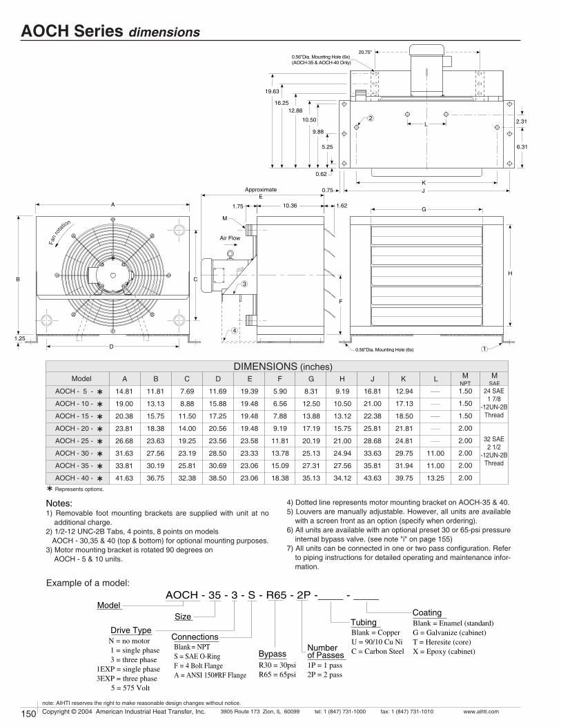
150 Copyright © 2004 American Industrial Heat Transfer, Inc. tel: 1 (847) 731-10003905 Route 173 Zion, IL 60099 www.aihti.comfax: 1 (847) 731-1010
note: AIHTI reserves the right to make reasonable design changes without notice.
151Copyright © 2004 American Industrial Heat Transfer, Inc. tel: 1 (847) 731-10003905 Route 173 Zion, IL 60099 www.aihti.comfax: 1 (847) 731-1010
note: AIHTI reserves the right to make reasonable design changes without notice.
AOCH Series dimensions
Model MNPT
LKJHFDCBA G
DIMENSIONS (inches)M
SAE7.69
8.88
11.50
14.00
19.25
23.19
25.81
32.38
8.31
12.50
13.88
17.19
20.19
25.13
27.31
35.13
11.81
13.13
15.75
18.38
23.63
27.56
30.19
36.75
14.81
19.00
20.38
23.81
26.68
31.63
33.81
41.63
9.19
10.50
13.12
15.75
21.00
24.94
27.56
34.12
11.69
15.88
17.25
20.56
23.56
28.50
30.69
38.50
19.39
19.48
19.48
19.48
23.58
23.33
23.06
23.06
5.90
6.56
7.88
9.19
11.81
13.78
15.09
18.38
16.81
21.00
22.38
25.81
28.68
33.63
35.81
43.63
12.94
17.13
18.50
21.81
24.81
29.75
31.94
39.75
____
____
____
____
____
11.00
11.00
13.25
1.50
1.50
1.50
2.00
2.00
2.00
2.00
2.00
AOCH - 5 -
AOCH - 10 -
AOCH - 15 -
AOCH - 20 -
AOCH - 25 -
AOCH - 30 -
AOCH - 35 -
AOCH - 40 -
24 SAE1 7/8
-12UN-2B Thread
32 SAE2 1/2
-12UN-2B Thread
AG
KJ
D1.25
ApproximateE
1.75 1.6210.36
0.56"Dia. Mounting Hole (6x)
M
2
B
F
HC
10.50
0.56"Dia. Mounting Hole (6x)(AOCH-35 & AOCH-40 Only)
9.88
5.25 6.31
2.31
0.62
0.75
12.8816.25
19.63
L
Fan
rota
tion
1
3
4
20.75"
Air Flow
NAMEPL
E
Notes:1) Removable foot mounting brackets are supplied with unit at no
additional charge.2) 1/2-12 UNC-2B Tabs, 4 points, 8 points on models AOCH - 30,35 & 40 (top & bottom) for optional mounting purposes.3) Motor mounting bracket is rotated 90 degrees on AOCH - 5 & 10 units.
4) Dotted line represents motor mounting bracket on AOCH-35 & 40.5) Louvers are manually adjustable. However, all units are available
with a screen front as an option (specify when ordering).6) All units are available with an optional preset 30 or 65-psi pressure
internal bypass valve. (see note "i" on page 155)7) All units can be connected in one or two pass configuration. Refer
to piping instructions for detailed operating and maintenance infor-mation.
AOCH - 35 - 3 - S - R65 - 2P -____ - ____Model
Size
Drive Type
Numberof Passes
Connections
BypassR30 = 30psiR65 = 65psi
CoatingBlank = Enamel (standard)G = Galvanize (cabinet)T = Heresite (core)X = Epoxy (cabinet)
TubingBlank = CopperU = 90/10 Cu NiC = Carbon Steel
1P = 1 pass2P = 2 pass
N = no motor 1 = single phase 3 = three phase1EXP = single phase3EXP = three phase 5 = 575 Volt
Blank = NPTS = SAE O-RingF = 4 Bolt Flange A = ANSI 150#RF Flange
Example of a model:
Ý Represents options.
Ý
Ý
Ý
Ý
Ý
Ý
Ý
Ý

150 Copyright © 2004 American Industrial Heat Transfer, Inc. tel: 1 (847) 731-10003905 Route 173 Zion, IL 60099 www.aihti.comfax: 1 (847) 731-1010
note: AIHTI reserves the right to make reasonable design changes without notice.
151Copyright © 2004 American Industrial Heat Transfer, Inc. tel: 1 (847) 731-10003905 Route 173 Zion, IL 60099 www.aihti.comfax: 1 (847) 731-1010
note: AIHTI reserves the right to make reasonable design changes without notice.
AOCH Series motor data
CLASS I,DIV.1, GROUP D or CLASS II,DIV.2, GROUP F & G EXPLOSION PROOF MOTOR DATA
115 / 230
230 / 460
115 / 230
230 / 460
115 / 230
230 / 460
115 / 230
230 / 460
115 / 230
230 / 460
115 / 230
230 / 460
230 / 460
230 / 460
AOCH - 5 - 1
AOCH - 5 - 3
AOCH - 10 - 1
AOCH - 10 - 3
AOCH - 15 - 1
AOCH - 15 - 3
AOCH - 20 - 1
AOCH - 20 - 3
AOCH - 25 - 1
AOCH - 25 - 3
AOCH - 30 - 1
AOCH - 30 - 3
AOCH - 35 - 3
AOCH - 40 - 3
56
56
56
56
56
56
56
56
56
56
56
56
182
182
6.8 / 3.4
1.6 / .8
6.8 / 3.4
1.6 / .8
8.8 / 4.4
2.4 / 1.2
8.8 / 4.4
2.4 / 1.2
13.4 / 6.7
3.6 / 1.8
13.4 / 6.7
3.6 / 1.8
8.8 / 4.4
8.8 / 4.4
1
3
1
3
1
3
1
3
1
3
1
3
3
3
YES
YES
YES
YES
YES
YES
YES
YES
YES
YES
YES
YES
YES
YES
1 / 2
1 / 2
1 / 2
1 / 2
1 / 2
1 / 2
1 / 2
1 / 2
1
1
1
1
3
3
60
60
60
60
60
60
60
60
60
60
60
60
60
60
3450
3450
3450
3450
1725
1725
1725
1725
1725
1725
1725
1725
1725
1725
X-PROOF
X-PROOF
X-PROOF
X-PROOF
X-PROOF
X-PROOF
X-PROOF
X-PROOF
X-PROOF
X-PROOF
X-PROOF
X-PROOF
X-PROOF
X-PROOF
1.0
1.0
1.0
1.0
1.0
1.0
1.0
1.0
1.0
1.0
1.0
1.0
1.0
1.0
ThermalOverload
Service FactorRPMHzPhase Volts Full Load
AmperesHorsePowerModel NEMA
Frame
NOTE: Basic electric drive units are supplied with one of the corresponding above listed motors.
1) TEFC motors are available for all models.2) Motor electrical ratings are an approximate guide and may vary between
motor manufacturers. Consult ratings on motor data plate prior to instal-lation and operation.
3) Explosion proof, high temperature, severe duty, chemical, IEC, Canadian Standards Association, and Underwriters Laboratory recognized motors are available upon request.
4) American Industrial reserves the right to enact changes to motor brand, type and ratings regarding horsepower, RPM,FLA,and service factor
for standard products without notice. All specific requirements will be honored without change.
5) Fan rotation is clockwise when facing the motor shaft.6) The above motors contain factory lubricated shielded ball bearings; no
additional lubrication is required.7) Abbreviation Index TEFC ...................Totally Enclosed, Fan Cooled X-PROOF ............Explosion Proof
ELECTRIC MOTOR NOTES:
EnclosureType
AOCH ELECTRIC MOTOR DATA
115 / 208-230
208-230 / 460-190 / 380
575
115 / 208-230
208-230 / 460-190 / 380
575
115 / 208 / 230
230 / 460-190 / 380
575
115 / 208 / 230
230 / 460-190 / 380
575
115 / 208-230
208-230 / 460-190 / 380
575
115 / 208-230
208-230 / 460-190 / 380
575
CONSULT FACTORY
208-230 / 460-190 / 380
575
CONSULT FACTORY
208-230 / 460-190 / 380
575
AOCH - 5 - 1
AOCH - 5 - 3
AOCH - 5 - 5
AOCH - 10 - 1
AOCH - 10 - 3
AOCH - 10 - 5
AOCH - 15 - 1
AOCH - 15 - 3
AOCH - 15 - 5
AOCH - 20 - 1
AOCH - 20 - 3
AOCH - 20 - 5
AOCH - 25 - 1
AOCH - 25 - 3
AOCH - 25 - 5
AOCH - 30 - 1
AOCH - 30 - 3
AOCH - 30 - 5
AOCH - 35 - 1
AOCH - 35 - 3
AOCH - 35 - 5
AOCH - 40 - 1
AOCH - 40 - 3
AOCH - 40 - 5
56
56
56
56
56
56
56
56
56
56
56
56
56
56
56
56
56
56
182T
182T
182T
182T
8.4 / 4-4.2
2.1-2.2 / 1.1-2.0 /1.0
.9
8.4 / 4-4.2
2.1-2.2 / 1.1-2.0 /1.0
.9
8.8 / 4.2-4.4
2.4 / 1.2
.9
8.8 / 4.2-4.4
2.4 / 1.2
.9
13.4 / 6.8-6.7
3.5-3.6 / 1.8-3.4 / 1.7
1.45
13.4 / 6.8-6.7
3.5-3.6 / 1.8-3.4
1.45
8 / 4-6.8 / 3.4
3.2
8 / 4-6.8 / 3.4
3.2
1
3
3
1
3
3
1
3
3
1
3
3
1
3
3
1
3
3
3
3
3
3
NO
NO
NO
NO
NO
NO
NO
NO
NO
NO
NO
NO
NO
NO
NO
NO
NO
NO
NO
NO
NO
NO
1 / 2
1 / 2
1 / 2
1 / 2
1 / 2
1 / 2
1 / 2
1 / 2
1 / 2
1 / 2
1 / 2
1 / 2
1
1
1
1
1
1
3
3
3
3
60
60 / 50
60
60
60 / 50
60
60
60 / 50
60
60
60 / 50
60
60
60 / 50
60
60
60 / 50
60
60 / 50
60
60 / 50
60
3450
3450
3450
3450
3450
3450
1725
1725
1725
1725
1725
1725
1725
1725
1725
1725
1725
1725
1725
1725
N / A
1725
1725
TEFC
TEFC
TEFC
TEFC
TEFC
TEFC
TEFC
TEFC
TEFC
TEFC
TEFC
TEFC
TEFC
TEFC
TEFC
TEFC
TEFC
TEFC
TEFC
TEFC
TEFC
TEFC
1.15
1.15
1.15
1.15
1.15
1.15
1.15
1.15
1.15
1.15
1.15
1.15
1.15
1.15
1.15
1.15
1.15
1.15
1.15
1.15
1.15
1.15
ThermalOverload
Service FactorRPMHzPhase Volts Full Load
AmperesHorsePowerModel NEMA
Frame
NOTE: Basic electric drive units are supplied with one of the corresponding above listed motors.
EnclosureType

152 Copyright © 2004 American Industrial Heat Transfer, Inc. tel: 1 (847) 731-10003905 Route 173 Zion, IL 60099 www.aihti.comfax: 1 (847) 731-1010
note: AIHTI reserves the right to make reasonable design changes without notice.
153Copyright © 2004 American Industrial Heat Transfer, Inc. tel: 1 (847) 731-10003905 Route 173 Zion, IL 60099 www.aihti.comfax: 1 (847) 731-1010
note: AIHTI reserves the right to make reasonable design changes without notice.
AOCHM Series dimensions
Model MNPT
LKJHFDCBA G
DIMENSIONS (inches)M
SAE7.69
8.88
11.50
14.00
19.25
23.19
25.81
32.38
8.31
12.50
13.88
17.19
20.19
25.13
27.31
35.13
11.81
13.13
15.75
18.38
23.63
27.56
30.19
36.75
14.81
19.00
20.38
23.81
26.68
31.63
33.81
41.63
9.19
10.50
13.12
15.75
21.00
24.94
27.56
34.12
11.69
15.88
17.25
20.56
23.56
28.50
30.69
38.50
15.21
15.21
15.21
15.21
15.21
15.21
15.21
15.21
5.90
6.56
7.88
9.19
11.81
13.78
15.09
18.38
16.81
21.00
22.38
25.81
28.68
33.63
35.81
43.63
12.94
17.13
18.50
21.81
24.81
29.75
31.94
39.75
____
____
____
____
____
11.00
11.00
13.25
1.50
1.50
1.50
2.00
2.00
2.00
2.00
2.00
AOCHM - 5 -
AOCHM - 10 -
AOCHM - 15 -
AOCHM - 20 -
AOCHM - 25 -
AOCHM - 30 -
AOCHM - 35 -
AOCHM - 40 -
24 SAE1 7/8
-12UN-2B Thread
32 SAE2 1/2
-12UN-2B Thread
AG
K
INLETPORT
OUTLETPORT
J
D1.25
ApproximateE
1.75 1.6210.36
0.56"Dia. Mounting Hole (6x)M *
2
B
F
HC
10.50
9.88
5.25 6.31
2.31
0.62
0.75
L
Fan
rota
tion
1
3
Air Flow
E
Notes :1) Removable foot mounting brackets are supplied with unit at no
additional charge.2) 1/2-12 UNC-2B Tabs, 4 points, 8 points on models AOCHM - 30,35
& 40 (top & bottom) for optional mounting purposes.3) Motor mounting bracket is rotated 90 degrees on AOCHM - 5 &
10 units.
4) Louvers are manually adjustable. However, all units are available with a screen front as an option (specify when ordering).
5) All units are available with an optional preset 30 or 65-psi pressure bypass valve. (see note "i" on page 155)
6) All units can be connected in one or two pass configuration. Re-fer to piping instructions for detailed operating and maintenance information.
AOCHM - 40 - 9 - S - R65 - 2P -____ - ____Model
Size
Drive Type
Numberof Passes
N = No motor 9 = Hydraulic
motor
Connections
Bypass
R30 = 30psiR65 = 65psi
CoatingBlank = Enamel (standard)G = Galvanize (cabinet)T = Heresite (core)X = Epoxy (cabinet)
TubingBlank = CopperU = 90/10 Cu NiC = Carbon Steel
1P = 1 pass2P = 2 pass
Blank = NPTS = SAE O-RingF = 4 Bolt Flange A = ANSI 150#RF Flange
Example of a model:
Ý Represents options.
HYDRAULIC MOTOR SCHEMATIC
Ý
Ý
Ý
Ý
Ý
Ý
Ý
Ý

152 Copyright © 2004 American Industrial Heat Transfer, Inc. tel: 1 (847) 731-10003905 Route 173 Zion, IL 60099 www.aihti.comfax: 1 (847) 731-1010
note: AIHTI reserves the right to make reasonable design changes without notice.
153Copyright © 2004 American Industrial Heat Transfer, Inc. tel: 1 (847) 731-10003905 Route 173 Zion, IL 60099 www.aihti.comfax: 1 (847) 731-1010
note: AIHTI reserves the right to make reasonable design changes without notice.
AOCHM Series motor dataHYDRAULIC MOTOR DATA
6.5
6.5
6.0
6.0
6.0
6.0
6.0
6.0
AOCHM - 5 -
AOCHM - 10 -
AOCHM - 15 -
AOCHM - 20 -
AOCHM - 25 -
AOCHM - 30 -
AOCHM - 35 -
AOCHM - 40 -
INT
INT
INT
INT
INT
INT
INT
INT
#12 1-1/16-12
#12 1-1/16-12
#12 1-1/16-12
#12 1-1/16-12
#12 1-1/16-12
#12 1-1/16-12
#12 1-1/16-12
#12 1-1/16-12
0.43
0.43
0.68
0.68
0.68
0.68
0.68
0.68
3000
3000
3000
3000
3000
3000
3000
3000
3000
3000
1725
1725
1725
1725
1725
1725
300
300
400
400
400
400
1000
1000
A
A
A
A
A
A
A
A
Max. ContinuousPressure PSIG
SAESize
Min. pressurestart / run PSIG
Displacementin3/Rev
Required FlowGPM LPM
Side PortSAE O-Ring
MotorRPM
Model CaseDrain
24.6
24.6
22.7
22.7
22.7
22.7
22.7
22.7
NOTES: Ý Represents options.
1) Standard units are supplied with a bi-directional hydraulic gear motor for the fan drive. The gear motor requires an external case drain be used during operation. The external case drain should be connected directly to hydraulic reservoir or a return line with not greater than 10PSIG back pressure. (NOTE: Failure to properly connect and use the external case drain during motor operation could result in motor failure and external leakage of hydraulic fluid.
2) Hydraulic motor flow requirements are provided with an efficiency rating of approximately 85%. Pressure requirements are calculated theoretical minimum operating requirements.
3) Shaft adapters are used to bridge the differences in length between the fan and hydraulic motor.
4) Maximum degree of fluid contamination, class 18/15 according to ISO 4406. Therefore, it is recommended to use a filter with retention rating of B20>. For longer life, it is recommended to use class 17/14 achiev-able with filter B10>-100.
5) Fan rotation is clockwise when facing the motor shaft.6) Optional displacement motors available upon request.7) American industrial reserves the right to enact changes to hydraulic
motor, brand, type, ratings, port sizes, or any additional non-specified attribute for standard products without notice. All specific requirements will be honored without change pending availability.
HYDRAULIC MOTOR NOTES:
COMMON DATA
85
85
80
80
81
84
89
91
Model - 5 -
Model - 10 -
Model - 15 -
Model - 20 -
Model - 25 -
Model - 30 -
Model - 35 -
Model - 40 -
.368
.523
.750
1.023
1.42
1.93
2.79
4.54
Sound LeveldB(A) @ 7ft
Air FlowCFM m3/s
Model
780
1110
1590
2168
3000
4095
5921
9609
3331
4126
4883
6735
8592
10826
13097
17865
Liquid Volumegal. cm3
.88
1.09
1.29
1.70
2.27
2.86
3.46
4.72
37
41
47
69
79
99
159
196
Weight Electriclb kg82
91
103
152
175
218
351
432
29
34
39
61
71
91
106
142
Weight Hydrauliclb kg64
73
85
134
157
200
233
314
NO
NO
NO
Yes
Yes
Yes
Yes
Yes
ServiceableCore
NOTES: a) Ý Represents the options for motor drive. b) To estimate the sound level at distances other than 13 feet (4 meters) from the cooler, add 6 db for each halving of distance, or substract
6 db for each doubling of the distance.
Ý
Ý
Ý
Ý
Ý
Ý
Ý
Ý
Ý
Ý
Ý
Ý
Ý
Ý
Ý
Ý
PIPING HOOK UP shown with relief valve
ONE PASS TWO PASS
Fan
rota
tion
FLUIDOUT
FLUIDIN
CAPPED
Fan
rota
tio
n
FLUIDOUT
FLUID IN

154 Copyright © 2004 American Industrial Heat Transfer, Inc. tel: 1 (847) 731-10003905 Route 173 Zion, IL 60099 www.aihti.comfax: 1 (847) 731-1010
note: AIHTI reserves the right to make reasonable design changes without notice.
155Copyright © 2004 American Industrial Heat Transfer, Inc. tel: 1 (847) 731-10003905 Route 173 Zion, IL 60099 www.aihti.comfax: 1 (847) 731-1010
note: AIHTI reserves the right to make reasonable design changes without notice.
Fan
rota
tion
FLUIDOUT
FLUIDIN
CAPPED
AOCH & AOCHM Series installation & maintenancePIPING HOOK UP
ONE PASS TWO PASS
Receiving / Installationa) Inspect unit for any shipping damage before uncrating. Indicate all damages to the trucking firms' delivery per-son and mark it on the receiving bill before accepting the freight. Make sure that the core and fan are not damaged. Rotate the fan blade to make sure that it moves freely. The published weight information located in this brochure is approximate. True shipment weights are determined at the time of shipping and may vary. Approximate weight information published herein is for engineering approxi-mation purposes and should not be used for exact shipping weight. Since the warranty is based upon the unit date code located on the model identification tag, removal or manipulation of the identification tag will void the manu-facturers warranty.
b) When handling the heat exchanger, special care should be taken to avoid damage to the core and fan. All units are shipped with wood skids for easy forklift handling
c) Standard Enamel Coating: American Industrial provides its standard products with a normal base coat of oil base air cure enamel paint. The enamel paint is applied as a temporary protective and esthetic coating prior to shipment. While the standard enamel coating is durable, American Industrial does not warranty it as a long-term finish coating. It is strongly suggested that a more durable final coating be applied after installation or prior to long-term storage in a corrosive environment to cover any accidental scratches, enhance esthetics, and further prevent corrosion. It is the responsibility of the customer to provide regular mainte-nance against chips, scratches, etc... and regular touch up maintenance must be provided for long-term benefits and corrosion prevention.
d) Special Coatings: American Industrial offers as customer options, Air-Dry Epoxy, and Heresite (Air-Dry Phenolic) coatings at additional cost. American Industrial offers spe-cial coatings upon request, however American Industrial does not warrantee coatings to be a permanent solution for any equipment against corrosion. It is the responsibility of
the customer to provide regular maintenance against chips, scratches, etc... and regular touch up maintenance must be provided for long-term benefits and corrosion prevention.
e) American Industrial recommends that the equipment supplied should be installed by qualified personnel who have solid understanding of system design, pressure and temperature ratings, and piping assembly. Verify the service conditions of the system prior to applying any air cooled heat exchanger series cooler. If the system pres-sure or temperature does not fall within the parameters on model rating tag located on the heat exchanger, contact our factory prior to installation or operation.
g) Heat exchanger should be securely fastened using the mounting foot brackets (included). All mounting holes should be used to secure unit into place. Optional horizontal mounting with vertical airflow is allowable by removing the foot brackets and using the (4 or 8) 1/2"-13 screw hard points located on the top and bottom panel for fastening. Heat exchanger unit must be set into a fabricated channel type frame with provision for additional motor support for heavy motors in conjunction with 1/2" frame fastening bolt points. Since the units are normally operated in the verti-cal position (horizontal airflow) reinforced motor support is suggested.
h) Connections should be made in "one pass" or "two pass" configurations exactly as indicated in the "piping hook up" illustration above. The process flow entering the "Fluid IN" port and exiting the "Fluid OUT" port eliminates air pockets and assures that the unit will stay completely flooded. Flexible hose can be applied to reduce the risk of core failure due to thermal expansion or system vibration. Piping alignment and support is required for hoses longer than four feet in length and for piping exerting more than 20 lbs of dynamic force. It is recommended that filtration be located ahead of the heat exchanger to prevent excessive backpressure and clogging.
Fan
rota
tio
n
FLUIDOUT
FLUID IN

154 Copyright © 2004 American Industrial Heat Transfer, Inc. tel: 1 (847) 731-10003905 Route 173 Zion, IL 60099 www.aihti.comfax: 1 (847) 731-1010
note: AIHTI reserves the right to make reasonable design changes without notice.
155Copyright © 2004 American Industrial Heat Transfer, Inc. tel: 1 (847) 731-10003905 Route 173 Zion, IL 60099 www.aihti.comfax: 1 (847) 731-1010
note: AIHTI reserves the right to make reasonable design changes without notice.
AOCH & AOCHM Series installation & maintenancei) With respect to the heat exchangers nozzle size, flow line sizes should be sized to handle the appropriate flow rate and system pressure drop requirements, normally flow line rates of about 8-12 feet per second and inlet pressure less than 100psig are experienced. If the flow line size is larger than the heat exchanger nozzle size, additional pressure loss beyond the published pressure loss data may occur.
j) Electric motors should be connected only to supply source of the same characteristics as indicated on the electric motor information plate. Prior to starting, verify that the motor and fan spin freely without obstruction. Check carefully that the fan turns in the correct rotation direction (normally counter clockwise) from the motor side (fan direction arrow). Failure to operate the fan in the proper direction could reduce performance or cause serious damage to the heat exchanger or other components. Fan blades should be rechecked for tightness after the first 100 hours of operation.
k) It is important to apply the catalog recommended flow rate for the hydraulic motor that corresponds with the spe-cific model being used. A case drain is required for hy-draulic motor installation. Failure to connect case drain can result in motor failure. The proper flow rate and direction to the hydraulic motor are critical to ensure fan direction and RPM. Exceeding the recommended RPM could result in fan failure and cause severe damage to the heat exchanger. See fan rotation on installation diagram.
MaintenanceRegular maintenance intervals based upon the surround-ing and operational conditions should be maintained to verify equipment performance and to prevent premature component failure. Since some of the components such as, motors, fans, load adapters, etc... are not manufactured by American Industrial, maintenance requirements provided by the manufacture must be followed.
a) Inspect the entire heat exchanger and motor/fan as-sembly for loosened bolts, loose connections, broken components, rust spots, corrosion, fin/coil clogging, or external leakage. Make immediate repairs to all affected areas prior to restarting and operating the heat exchanger or its components.
b) Heat exchangers operating in oily or dusty environments will often need to have the coil cooling fins cleaned. Oily or clogged fins should be cleaned by carefully brushing the fins and tubes with water or a non-aggressive degreasing agent mixture (Note: Cleaning agents that are not compat-ible with copper, brass, aluminum, steel or stainless steel should not be used). A compressed air or a water stream can be used to dislodge dirt and clean the coil further. Any external dirt or oil on the electric motor and fan assembly should be removed. Caution: Be sure to disconnect the electric motor from its power source prior to doing any maintenance.
c) In most cases it is not necessary to internally flush the coil. In circumstances where the coil has become plugged
or has a substantial buildup of material, flushing the coil with water or a solvent may be done. Flushing solvents should be non-aggressive suitable for the materials of con-struction. Serviceable Core® models can be disassembled and inspected or cleaned if required. d) Most low horsepower electric motors do not require any additional lubrication. However, larger motors must be lubricated with good quality grease as specified by the manufacture at least once every 6-9 months or as directed by the manufacture. T.E.F.C. air ventilation slots should be inspected and cleaned regularly to prevent clogging and starving the motor of cooling air. To maintain the electric motor properly see the manufactures requirements and specifications.
e) Fan blades should be cleaned and inspected for tight-ness during the regular maintenance schedule when han-dling a fan blade care must be given to avoid bending or striking any of the blades. Fan blades are factory balanced and will not operate properly if damaged or unbalanced. Damaged fan blades can cause excessive vibration and severe damage to the heat exchanger or drive motor. Replace any damaged fan with an American industrial suggested replacement.
f) Air cooled exchanger cabinets are constructed using 7ga. through 18ga. steel that may be bent back into position if damaged. Parts that are not repairable can be purchased through American Industrial.
g) Coil fins that become flattened can be combed back into position. This process may require removal of the coil from the cabinet.
h) It is not advisable to attempt repairs to brazed joints of a brazed construction coil unless it will be done by an expert in silver solder brazing. Brazed coils are heated uniformly during the original manufacturing process to prevent weak zones from occurring. Uncontrolled reheating of the coil may result in weakening of the tube joints surrounding the repair area. In many instances brazed units that are repaired will not hold up as well to the rigors of the system as will a new coil. American Industrial will not warranty or be responsible for any repairs done by unauthorized sources. Manipulation in any way other than normal application will void the manufactures warranty.
i) Solely at the request of customers, American Industrial provides direct acting internal inlet port to outlet port bypass relief valves as an additional safe guard against excessive flow and over pressurization of the heat exchanger. Ameri-can Industrial purchases and applies high quality hydraulic system cartridge valves and components made available for hydraulic system use. However, American Industrial does not specify, recommend, suggest, guarantee, or warrantee the internal relief valve or its performance to safe guard the heat exchanger from damage or prevent failure due to excessive flow or over pressurization. It is the ultimately the sole responsibility of the customer/user to verify with the original equipment manufacture all conditions associated with applying an additional system relief valve prior to application.

156 Copyright © 2004 American Industrial Heat Transfer, Inc. tel: 1 (847) 731-10003905 Route 173 Zion, IL 60099 www.aihti.comfax: 1 (847) 731-1010
note: AIHTI reserves the right to make reasonable design changes without notice.
157Copyright © 2004 American Industrial Heat Transfer, Inc. tel: 1 (847) 731-10003905 Route 173 Zion, IL 60099 www.aihti.comfax: 1 (847) 731-1010
note: AIHTI reserves the right to make reasonable design changes without notice.
AOCH & AOCHM Series installation & maintenance
1
2
3
4
6
5
Serviceable Core® MaintenanceUnits containing a Serviceable Core® have bolted mani-fold covers that can be removed for cleaning or repair purposes.
Servicing SequenceAmerican Industrial has gone to great lengths to provide components that are repairable. If the heat exchanger core requires internal cleaning or attention the following steps will explain what must be done to access the internal tubes. Be sure to order gasket kits or repair parts prior to removal and disassembly to minimize down time.
a) To clean the internal tubes first remove all connection plumbing from the unit.
b) Be sure the unit is drained of all water etc...
c) Place the heat exchanger in an area that it can be ac-cessed from all sides. Remove the core from the cabinet if required (AOCH, AOCS).
d) Mark the cover À and tube-sheet  for both covers so that they can be replaced into the same position when finished. Remove the manifold cover bolts Á and hardware and place them into a secure place.
e) The manifold covers are tightly compressed and may need some prying to separate them from the gasket Å, physically remove the cover assemblies À from both sides.
f) The tubes à and turbulators Ä are now accessible for cleaning. Note: turbulators are installed on AOCH & AOCS cores only. If you need to remove the turbulator that runs through the tubing, it will be necessary to first squeeze the flattened end of the protruding turbulator Ä, so that on end will fit through the tube. From the opposite end pull the turbulator Ä out. You may need to use pliers to grip and pull the turbulators Ä out, especially if there is debris lodged inside. As the turbulators Ä come out, most of the dirt will too, so be prepared. It is suggested that gloves be worn when handling the turbulators Ä as they may be sharp.
We suggest a mild water-soluble degreaser be used with a brush. Tubing I.D. is aproximatley .325 a plastic bristle brush on a rod will work best for cleaning the tubes Ã. Steel brushes should be avoided since the steel is harder than the copper tubing and may heavily score the tubes à if used.
g) If there are any leaking tubes à you may plug them by carefully forcing a soft metal plug into the hole and tapping it tight. You may in some cases weld the leaking tube shut however, care should be taken since excessive heat may cause surrounding tube joints to loosen and leak.
h) When finished cleaning or repairing, be sure to re-place ALL of the turbulators Ä back into any open tubes Ã. When the turbulators Ä protrude from the opposite end flatten them again so they are tight and cannot be removed.
i) When finished reattach the manifold covers À in the same position they were removed, using new gaskets Å, bolts Á, and hardware. We suggest using a torque wrench to final tighten the bolts Á.
j) Torque Specifications: For 5/16" bolts 22-23 ft-lbs, for 3/8" bolts to 38-42 ft-lbs. Since bolts and hardware can physically fatigue during application we suggest new bolt kits be used when reassembling.
American Industrial's state-of-the-art manufacturing facility.

156 Copyright © 2004 American Industrial Heat Transfer, Inc. tel: 1 (847) 731-10003905 Route 173 Zion, IL 60099 www.aihti.comfax: 1 (847) 731-1010
note: AIHTI reserves the right to make reasonable design changes without notice.
157Copyright © 2004 American Industrial Heat Transfer, Inc. tel: 1 (847) 731-10003905 Route 173 Zion, IL 60099 www.aihti.comfax: 1 (847) 731-1010
note: AIHTI reserves the right to make reasonable design changes without notice.
AIR COOLED
OIL COOLERS• Severe duty construction with OSHA guard.
• Serviceable Core®.
• Thermal capacity to 1,400 hp (1,043 Kw).
• Operating temperature of 300°F at 200 PSI.
• Electric, hydraulic, or external drive.
• Optional: built-in bypass valve.
• Can be customized to fit your needs.
AOCS SERIES
• Field changeable drive from electric to hy-
draulic.
• Cools: Fluid power systems, rock crushers,
conveyors, shredders, lubrication equipment
for paper machinery, gear drives, offshore
drilling equipment, etc.
®

158 Copyright © 2004 American Industrial Heat Transfer, Inc. tel: 1 (847) 731-10003905 Route 173 Zion, IL 60099 www.aihti.comfax: 1 (847) 731-1010
note: AIHTI reserves the right to make reasonable design changes without notice.
159Copyright © 2004 American Industrial Heat Transfer, Inc. tel: 1 (847) 731-10003905 Route 173 Zion, IL 60099 www.aihti.comfax: 1 (847) 731-1010
note: AIHTI reserves the right to make reasonable design changes without notice.
AOCS Series overview
AOCS Series WITH ELECTRIC DRIVE
Severe duty air-cooled oil coolers, super capacity, rolled tube industrial series heat exchangers with direct electric drive cooling fan, OSHA guard, and heavy duty front screen. Rated operating temperature of 300oF at 200 PSIG. Standard flow rates from 10 to 600 GPM. NPT, ANSI flange, or SAE code 61 four bolt flange port connections. Optional built-in bypass relief valve 30 PSI or 65 PSI. Can be modified to meet your requirements. Suitable for most hydraulic oils, lubrications oils, synthetic compressor oils, ethylene glycol, and many other fluids compatible with listed material.
AOCS Series Durable design offered in eleven sizes available from stock for fast delivery.
AOCS Series WITH HYDRAULIC DRIVE
Severe duty air-cooled oil coolers, super capacity, rolled tube industrial series heat exchangers with direct hydraulic drive cooling fan, OSHA guard, and heavy duty front screen. Rated operating temperature of 300oF at 200 PSIG. Standard flow rates from 10 to 600 GPM. NPT, ANSI flange, or SAE code 61 four bolt flange port connections. Optional built-in bypass relief valve 30 PSI or 65 PSI. Can be modified to meet your requirements. Suitable for most hydraulic oils, lubrications oils, synthetic compressor oils, ethylene glycol, and many other fluids compatible with listed material.

158 Copyright © 2004 American Industrial Heat Transfer, Inc. tel: 1 (847) 731-10003905 Route 173 Zion, IL 60099 www.aihti.comfax: 1 (847) 731-1010
note: AIHTI reserves the right to make reasonable design changes without notice.
159Copyright © 2004 American Industrial Heat Transfer, Inc. tel: 1 (847) 731-10003905 Route 173 Zion, IL 60099 www.aihti.comfax: 1 (847) 731-1010
note: AIHTI reserves the right to make reasonable design changes without notice.
AOCS Series construction
HIGH PERFORMANCE TURBULATOR Exclusive American Industrial Turbulators installed
in every flow tube, increase heat transfer by more than
100%.
American Industrial Turbulators eliminate the laminar
flow condition normally associated with other smooth
tube heat exchangers. High viscosity hydraulic and lubri-
cating oils are easily cooled by this new state of the art
turbulator.
SERVICEABLE CORE ®
Core covers disassemble for easy access and cleaning.
Repairable design for applications that required limited
down time. Roller expanded tube to tube-sheet joint.
100% mechanical bond, no braze or solder joint to
fatigue fail, corrode, crack, etc.. No rubber grommets to
replace. Positive gasket seal is field replaceable for field
maintenance or repair.
SUPERIOR COOLING FINS
Copper tubes are mechanically bonded to highly effi-
cient aluminum cooling fins. Die-formed fin collars provide
a durable precision fit for maximum heat transfer.
Custom fin design forces air to become
turbulent and carry heat away more efficiently than old
flat fin designs.
Tubes Copper
Fins Aluminum
Turbulators Steel
Tube sheet Steel
Manifold cover Steel
Connection pipes Steel
Cabinet & frame Steel
Fan Blade Steel/Aluminum
Fan Guard Zinc Plated Steel
Gasket Hypalon Composite
316L Stainless Steel, 90/10 Cu.Ni, Carbon Steel
Copper
Brass
316L Stainless Steel, Brass
316L Stainless Steel, Brass
316L Stainless Steel, Brass
316L Stainless Steel, Galvanized Steel
Non-sparking, Nylon Composite
–
Viton, Nitrile, Composites
CONSTRUCTION MATERIALS & RATINGS
Operating Pressure 200 psig
Operating Temperature 300 oF
Max. Flow Internal Relief 132 gpm
(see note "i" on page 168 for relief valve)
Max. Fan Over-speed 10 %
Max. Ambient Conditions 124 oF
Altitude 0-3000 ft.
Standard Construction Materials Optional Construction Materials Standard Unit Ratings
Consult factory for optional materials and ratings

160 Copyright © 2004 American Industrial Heat Transfer, Inc. tel: 1 (847) 731-10003905 Route 173 Zion, IL 60099 www.aihti.comfax: 1 (847) 731-1010
note: AIHTI reserves the right to make reasonable design changes without notice.
161Copyright © 2004 American Industrial Heat Transfer, Inc. tel: 1 (847) 731-10003905 Route 173 Zion, IL 60099 www.aihti.comfax: 1 (847) 731-1010
note: AIHTI reserves the right to make reasonable design changes without notice.
AOCS Series selection
SizingThe performance curves provided are for petroleum oil at 63 ssu viscosity. However, fluids with characteristics other than the above mentioned may be used by applying a correction factor.
Heat LoadIf the heat load is unknown, a horsepower value can be calculated by first determining the systems total potential. For a basic hydraulic system, it is helpful to know whether the system is open loop (with a large res-ervoir) or closed loop (normally on mobile equipment, with a very small reservoir). System potentials may be calculated quickly by using one of the two methods below.
There are some system parameters that will be required to properly accomplish the sizing calculations. Without system parameters it is difficult to determine the optimal heat exchanger size. Normally many of the system parameters can be found on hydraulic schematics or on tags located on the actual equipment. Following are some basic parameters that you should try to acquire before attempting the sizing calculations. However, it is not necessary to have every parameter listed below.
• Main system flow rate (gpm) & operating pressure (psi). • Electric motor HP driving hydraulic pump (if more than one add up
the Hp for all). • Desired temperature (°F). • Fluid type (SAE 10, 20, 30, etc....). • Ambient air temperature (warmest day). • Desired fan drive (hydraulic, electric, 12-24V DC, etc...). • BTU's or HP to be cooled (normally given for lubrication systems). • Maximum pressure drop allowed through the heat exchanger. • Space available for heat exchanger (LxWxH).
Method 1Normally used for open loop circuits. Multiply the main hydraulic sys-tems Electric Motor Name plate Horsepower by a heat removal factor (normally 30-50%).
Example: 50 HP motor x 0.3 = 15 HP heat load
Method 2Normally used when the HP input potential is unknown or for mobile appli-cations where diesel engines operate the entire system. Multiply system
pressure by the flow rate of the main system divided by 1714 equals system potential (HP). Multiply the system HP by a heat removal factor (Normally 25-35%). Note: In some closed loop systems only a portion of the total system flow is directed through the heat exchanger, this may affect the cooler selection process substantially. You may contact our factory for additional technical assistance.
Example:
Determining Fs valueTo determine the proper size heat exchanger for your application, use the following equation to first determine the (Fs) factor.
Fs =
Example: Heat load = 50 HP Cv = 1.14 (SAE 20) determined from chart. [Located on page 4.] Desired operating temperature = 120 ºFAmbient air temp. = 100 ºF
Fs = = 7254
SelectionTo select a model, locate the flow rate (GPM) at the bottom of the flow vs Fs graph. Proceed upward until the GPM flow rate intersects with the calculated Fs. The curve closest above the intersection point will meet these conditions.
Example: Fs = 7254 = Model = AOCS - 1505 - * GPM = 40 PASSES = 2
Pressure differentialsDetermine the oil pressure drop from the curves as indicated. For vis-cosities other than 63 ssu, multiply the actual indicated pressure drop for your GPM flow by the value shown in the pressure differential curve for your viscosity value.
Example: AOCS-1505 @ 40 gpm & 63 ssu -2 pass curve- Indicated pressure drop 5 psi (Approx) { 5 psi x 2.8Cp (for SAE-20 oil) } = 14.0 corrected psi
(2000 psi x 30 gpm) = [35 HP x .25] = 8.75 HP heat load _______________ 1714
{ heat load (HP) x 2545 x Cv } __________________________{ °F (oil leaving - air entering) }
{ 50 x 2545 x 1.14 } ________________{ 120 °F - 100 °F }
Cv VISCOSITY CORRECTION FACTORS
ISO
22
SA
E 3
0
SA
E 1
0
SA
E 5
1.381.321.271.241.191.161.040.98
1.251.201.171.131.111.091.010.97
1.151.121.101.081.051.040.990.96
1.451.401.351.291.251.221.070.99
1.111.091.061.041.031.010.980.95
50%
ETH
YLE
NE
GLY
CO
L&
WA
TER
POLY
GLY
CO
L
0.920.890.880.850.840.830.790.76
PHO
SPH
ATE
ES
TER
0.830.800.790.770.760.740.710.69
0.850.840.840.830.820.820.800.79
Average
Liquid
Temperature
100110120130140150200250
ISO
32
1.081.061.041.031.021.020.980.95
ISO
46
1.141.131.111.091.081.060.990.96
ISO
68
1.181.161.141.131.101.091.000.96
ISO
100
1.261.251.201.171.161.131.010.96
ISO
150
1.371.311.271.241.201.171.020.97
ISO
220
1.431.391.351.301.261.221.080.99
ISO
320
1.561.481.401.341.301.271.091.01
SA
E 4
0
MIL
-L-7
808
1.191.141.091.051.031.010.980.97
SA
E 2
0
1.841.671.531.441.391.331.141.02
Cp PRESSURE DROP CORRECTION FACTORS
ISO
22
SA
E 3
0
SA
E 1
0
SA
E 5
6.405.104.203.402.902.501.400.97
4.403.603.002.602.231.901.200.92
2.402.101.801.601.501.300.960.82
8.806.705.604.503.703.101.601.05
2.001.701.501.401.301.200.930.81
50%
ETH
YLE
NE
GLY
CO
L&
WA
TER
POLY
GLY
CO
L
3.002.402.101.901.901.701.201.00
PHO
SPH
ATE
ESTE
R
3.502.902.502.202.001.901.301.05
0.7300.7200.7090.6980.6860.6760.6350.556
Average
Liquid
Temperature
100110120130140150200250
ISO
32
1.071.041.020.990.970.950.890.85
ISO
46
1.531.451.381.301.231.170.990.93
ISO
68
1.821.721.601.491.381.301.080.96
ISO
100
2.542.352.151.941.751.611.181.03
ISO
150
4.193.733.262.802.382.041.331.11
ISO
220
6.445.704.914.143.472.901.591.21
ISO
320
9.388.337.236.195.204.351.741.22
SA
E 4
0
MIL
-L-7
808
1.261.201.141.081.030.980.900.83
SA
E 2
0
13.5611.63 9.73 7.80 6.11 4.77 1.95 1.23

160 Copyright © 2004 American Industrial Heat Transfer, Inc. tel: 1 (847) 731-10003905 Route 173 Zion, IL 60099 www.aihti.comfax: 1 (847) 731-1010
note: AIHTI reserves the right to make reasonable design changes without notice.
161Copyright © 2004 American Industrial Heat Transfer, Inc. tel: 1 (847) 731-10003905 Route 173 Zion, IL 60099 www.aihti.comfax: 1 (847) 731-1010
note: AIHTI reserves the right to make reasonable design changes without notice.
Horsepower to be removed (HP) x 2545 x Cv °F (Oil Leaving* - Ambient Air Entering) Fs =
OIL PRESSURE DROP (PSI) CODE
BTUhr oF
=
Note: When a model selection has been made, record whether the selection was from the one pass curve or the two pass curve so that the unit can be properly plumbed. Incorrect installation can seriously affect the performance.
PERFORMANCE CALCULATION
*Represents desired fluid leaving the cooler.
AOCS Series performance
E = 5 PSIF = 10 PSIG = 15 PSI
H = 20 PSI I = 25 PSIJ = 30 PSI
K = 35 PSIB = 2 PSIC = 3 PSID = 4 PSI
10 100 1000
Fs
GPM
1000
10000
700
70000ONE PASS
2000
4000
6000
8000
20000
40000
60000
20 30 40 50 60 70 80 200 300 400 500 600 800
AOCS-201
AOCS-303
AOCS-453
AOCS-603
AOCS-1005
AOCS-1505AOCS-2010
AOCS-2515AOCS-3120
AOCS-3525
AOCS-4030
BA
C DAB C D E
E
E
F
FAB C D
F G
AB C D E
F G H I
AB C D E
F G H I J
AB C D E
F G H I
I
J K
F G H J K
B C D E
F G H I J K
B C D E
F G H I J K
B C D E
F G H I J KB C D E
B C D E
1000
10000
100000
10 100 500
200000
20 40 6050 8070 90 30030 200 400
TWO PASS
GPM
Fs
2000
4000
6000
8000
20000
40000
60000
80000
AOCS-201
AOCS-303
AOCS-453
AOCS-603
AOCS-1005
AOCS-1505
AOCS-2010
AOCS-2515
AOCS-3120
AOCS-3525
AOCS-4030
E
E
E
F
F
F
F G
G
G
G
E
F G H
H
H
H
H
I
I
I
I
E
J
J
J
J
F G H I J
K
K
K
K
K
K
K
K
F G H IEJ K
E
F G H I JE
F G H I JE
F G H I JE
F G H I JE

162 Copyright © 2004 American Industrial Heat Transfer, Inc. tel: 1 (847) 731-10003905 Route 173 Zion, IL 60099 www.aihti.comfax: 1 (847) 731-1010
note: AIHTI reserves the right to make reasonable design changes without notice.
163Copyright © 2004 American Industrial Heat Transfer, Inc. tel: 1 (847) 731-10003905 Route 173 Zion, IL 60099 www.aihti.comfax: 1 (847) 731-1010
note: AIHTI reserves the right to make reasonable design changes without notice.
AOCS Series dimensions with electric drive
AIR FLOW
M 8.0
TFan Dia.
N
J A
D
H
K.62"X1.50"Thru Slot (6x)
.50"Drain Plug (2x)
1.25" NPTFiller Tube
L
C B
E E
G GFL
Fan
ro
tation
AIR FLOW
M
7.0
TFan Dia.
F
JA
D
H
K.62"X1.50"Thru Slot (6x)
.50"Drain Plug
1.25" NPT Filler Tube
L
C B
E E
G GNL
Fan
ro
tation
AOCS - 201 through AOCS - 603
ÝRepresents the options for motor drive.
AOCS - 1005 through AOCS - 4030
20.56
21.94
23.06
23.06
24.88
24.88
32.13
34.78
34.78
40.00
40.00
1.38
1.88
1.88
2.13
3.50
3.50
4.50
4.50
4.50
4.50
4.50
23.50
27.50
33.00
38.00
45.00
53.00
59.50
67.25
69.50
74.00
80.00
27.13
32.38
36.38
42.38
49.00
56.00
65.00
73.25
79.25
85.25
91.25
24.50
29.00
33.00
38.75
43.50
50.50
58.00
66.00
72.00
78.00
84.00
13.63
16.38
18.50
21.62
25.00
28.50
33.00
37.00
40.00
43.00
46.00
6.00
7.00
8.00
10.00
10.50
12.50
15.00
16.00
17.00
18.00
20.00
1.25
1.25
1.50
1.50
2.00
2.00
3.00
3.00
3.00
3.00
3.00
11.00
13.00
15.75
18.25
21.75
25.75
29.00
32.87
34.00
36.25
39.25
7.38
7.38
8.81
8.81
7.81
7.69
11.06
11.06
11.06
13.00
13.00
5.00
5.00
5.00
5.00
7.50
7.00
7.50
7.50
7.50
7.50
7.50
9.00
9.00
9.00
9.00
13.50
13.50
15.50
15.50
15.50
18.00
18.00
1.50
2.00
2.00
2.50
3.00
3.00
4.00
4.00
4.00
4.00
4.00
18.00
22.00
28.00
32.00
36.00
42.00
48.00
54.00
60.00
60.00
60.00
Model NNPTMLKJGF
NPTEDCBA H
DIMENSIONS (inches)T
AOCS-201 -
AOCS-303 -
AOCS-453 -
AOCS-603 -
AOCS-1005-
AOCS-1505-
AOCS-2010-
AOCS-2515-
AOCS-3120-
AOCS-3525-
AOCS-4030-
1.50
2.00
2.00
2.50
3.00
3.00
4.00
4.00
4.00
4.00
4.00
1.25
1.25
1.50
1.50
2.00
2.00
3.00
3.00
3.00
3.00
3.00
F*SAE
N*SAE
(F* and N*) are SAE code 61 four bolt flanges
Ý
Ý
Ý
Ý
Ý
Ý
Ý
Ý
Ý
Ý
Ý

162 Copyright © 2004 American Industrial Heat Transfer, Inc. tel: 1 (847) 731-10003905 Route 173 Zion, IL 60099 www.aihti.comfax: 1 (847) 731-1010
note: AIHTI reserves the right to make reasonable design changes without notice.
163Copyright © 2004 American Industrial Heat Transfer, Inc. tel: 1 (847) 731-10003905 Route 173 Zion, IL 60099 www.aihti.comfax: 1 (847) 731-1010
note: AIHTI reserves the right to make reasonable design changes without notice.
AOCS Series motor dataELECTRIC MOTOR DATA
230/460 - 190/380
575
230/460 - 190/380
575
230/460 - 190/380
575
230/460 - 190/380
575
230/460 - 190/380
575
230/460 - 190/380
575
230/460 - 190/380
575
230/460 - 190/380
575
230/460 - 190/380
575
230/460 - 190/380
575
230/460 - 190/380
575
AOCS-201 - 3
AOCS-201 - 5
AOCS-303 - 3
AOCS-303 - 5
AOCS-453 - 3
AOCS-453 - 5
AOCS-603 - 3
AOCS-603 - 5
AOCS-1005- 3
AOCS-1005- 5
AOCS-1505- 3
AOCS-1505- 5
AOCS-2010- 3
AOCS-2010- 5
AOCS-2515- 3
AOCS-2515- 5
AOCS-3120- 3
AOCS-3120- 5
AOCS-3525- 3
AOCS-3525- 5
AOCS-4030- 3
AOCS-4030- 5
143T
143T
182T
182T
213T
213T
213T
213T
215T
215T
215T
215T
256T
256T
284T
284T
286T
286T
324T
324T
326T
326T
3.2/1.6 - 3/1.5
1.2
8/4-6.8/3.4
3.2
9.2/4.6 - 8/4
4.1
9.2/4.6 - 8/4
4.1
14/7 - 11.2/5.6
6.0
14/7 - 11.2/5.6
6.0
28/14 25.4/12.7
10.5
40/20 - 33/16.5
16.3
54/27 - 50/25
21.4
67/33.5 - 65/32.5
25.6
76/38 - 76/38
30.8
3
3
3
3
3
3
3
3
3
3
3
3
3
3
3
3
3
3
3
3
3
3
NO
NO
NO
NO
NO
NO
NO
NO
NO
NO
NO
NO
NO
NO
NO
NO
NO
NO
NO
NO
NO
NO
1 / .75
1
3 / 2
3
3 / 2
3
3 / 2
3
5 / 3
5
5 / 3
5
10 / 7.5
10
15 / 10
15
20 / 15
20
25 / 20
25
30 / 25
30
60 / 50
60
60 / 50
60
60 / 50
60
60 / 50
60
60 / 50
60
60 / 50
60
60 / 50
60
60 / 50
60
60 / 50
60
60 / 50
60
60 / 50
60
1745/1450
1725
1760/1475
1725
1160/980
1160
1160/980
1160
1160/980
1160
1160/980
1160
1160/980
1160
1160/980
1160
1160/980
1160
1160/980
1160
1160/980
1160
TEFC
TEFC
TEFC
TEFC
TEFC
TEFC
TEFC
TEFC
TEFC
TEFC
TEFC
TEFC
TEFC
TEFC
TEFC
TEFC
TEFC
TEFC
TEFC
TEFC
TEFC
TEFC
1.15
1.15
1.15
1.15
1.15
1.15
1.15
1.15
1.15
1.15
1.15
1.15
1.15
1.15
1.15
1.15
1.15
1.15
1.15
1.15
1.15
1.15
ThermalOverload
Service FactorTypeRPMHzPhase Volts Full Load
AmperesHorsePowerModel NEMA
Frame
NOTE: Basic electric drive units are supplied with one of the corresponding above listed motors.
1) All standard direct drive models are supplied with TEFC electric motor for continuous duty at 104oF (40oC).
2) The above motor electrical ratings are an approximate guide and may vary slightly between motor manufactures. Consult motor ratings listed directly on motor data plate prior to instal-lation and operation
3) High altitude, high temperature, severe duty, crusher duty, chemical, IEC, Canadian Standards Association, and Un-derwriters Laboratory recognized motors are available upon
request.4) American industrial Heat Transfer, Inc. reserves the right to
enact changes to motor brand, type, and ratings regarding horsepower, RPM, FLA, and Service factor for standard prod-ucts without notice. All specified customer requirements will be honored without change or as directed.
5) Fan rotation is clockwise facing the motor shaft.6) For lubrication information refer to manufactures maintenance
instructions.
ELECTRIC MOTOR NOTES:
CLASS I,DIV.1, GROUP D or CLASS II,DIV.2, GROUP F & G EXPLOSION PROOF MOTOR DATA
230 / 460
230 / 460
230 / 460
230 / 460
230 / 460
230 / 460
230 / 460
230 / 460
230 / 460
230 / 460
230 / 460
AOCS-201 - 3EXP
AOCS-303 - 3EXP
AOCS-453 - 3EXP
AOCS-603 - 3EXP
AOCS-1005- 3EXP
AOCS-1505- 3EXP
AOCS-2010- 3EXP
AOCS-2515- 3EXP
AOCS-3120- 3EXP
AOCS-3525- 3EXP
AOCS-4030- 3EXP
143T
182T
213T
213T
215T
215T
256T
284T
286T
324T
326T
3.0 / 1.5
8.4 / 4.2
8.8 / 4.4
8.8 / 4.4
13.8 / 6.9
13.8 / 6.9
26 / 13
40 / 20
54 / 27
67 / 33.5
76 / 38
3
3
3
3
3
3
3
3
3
3
3
YES
YES
YES
YES
YES
YES
YES
YES
YES
YES
YES
1
3
3
3
5
5
10
15
20
25
30
60
60
60
60
60
60
60
60
60
60
60
1725
1725
1160
1160
1160
1160
1160
1160
1160
1160
1160
EPFC
EPFC
EPFC
EPFC
EPFC
EPFC
EPFC
EPFC
EPFC
EPFC
EPFC
1.15
1.15
1.15
1.15
1.15
1.15
1.15
1.15
1.15
1.15
1.15
ThermalOverload
Service FactorRPMHzPhase Volts Full Load
AmperesHorsePowerModel NEMA
Frame
NOTE: Basic electric drive units are supplied with one of the corresponding above listed motors.
EnclosureType

164 Copyright © 2004 American Industrial Heat Transfer, Inc. tel: 1 (847) 731-10003905 Route 173 Zion, IL 60099 www.aihti.comfax: 1 (847) 731-1010
note: AIHTI reserves the right to make reasonable design changes without notice.
165Copyright © 2004 American Industrial Heat Transfer, Inc. tel: 1 (847) 731-10003905 Route 173 Zion, IL 60099 www.aihti.comfax: 1 (847) 731-1010
note: AIHTI reserves the right to make reasonable design changes without notice.
AIR FLOW
M
7.0
TFan Dia.
F
JA
D
H
K.62"X1.50"Thru Slot (6x)
.50"Drain Plug
1.25" NPT Filler Tube
L
C B
E E
G GNL
Fan
ro
tation
AOCS Series dimensions with hydraulic drive
AIR FLOW
M 8.0
TFan Dia.
N
J A
D
H
K.62"X1.50"Thru Slot (6x)
.50"Drain Plug (2x)
1.25" NPTFiller Tube
L
C B
E E
G GFL
Fan
ro
tation
AOCS - 201 through AOCS - 603
AOCS - 1005 through AOCS - 4030
20.56
21.94
23.06
23.06
24.88
24.88
32.13
34.78
34.78
40.00
40.00
1.38
1.88
1.88
2.13
3.50
3.50
4.50
4.50
4.50
4.50
4.50
23.50
27.50
33.00
38.00
45.00
53.00
59.50
67.25
69.50
74.00
80.00
27.13
32.38
36.38
42.38
49.00
56.00
65.00
73.25
79.25
85.50
91.50
24.50
29.00
33.00
38.75
43.50
50.50
58.00
66.00
72.00
78.00
84.00
13.63
16.38
18.50
21.62
25.00
28.50
33.00
37.00
40.00
43.00
46.00
6.00
7.00
8.00
10.00
10.50
12.50
15.00
16.00
17.00
18.00
20.00
1.25
1.25
1.50
1.50
2.00
2.00
3.00
3.00
3.00
3.00
3.00
11.00
13.00
15.75
18.25
21.75
25.75
29.00
32.87
33.25
37.00
40.00
7.38
7.38
8.81
8.81
7.81
7.69
11.06
11.06
11.06
13.00
13.00
5.00
5.00
5.00
5.00
7.50
7.00
7.50
7.50
9.00
9.00
9.00
9.00
9.00
9.00
9.00
13.50
13.50
15.50
15.50
15.50
18.00
18.00
1.50
2.00
2.00
2.50
3.00
3.00
4.00
4.00
4.00
4.00
4.00
18.00
22.00
28.00
32.00
36.00
42.00
48.00
54.00
60.00
60.00
60.00
Model N NPT
MLKJGFNPTEDCBA H
DIMENSIONS (inches)T
AOCS-201 - 9
AOCS-303 - 9
AOCS-453 - 9
AOCS-603 - 9
AOCS-1005- 9
AOCS-1505- 9
AOCS-2010- 9
AOCS-2515- 9
AOCS-3120- 9
AOCS-3525- 9
AOCS-4030- 9
1.50
2.00
2.00
2.50
3.00
3.00
4.00
4.00
4.00
4.00
4.00
1.25
1.25
1.50
1.50
2.00
2.00
3.00
3.00
3.00
3.00
3.00
F*SAE
N*SAE
(F* and N*) are SAE code 61 four bolt flanges

164 Copyright © 2004 American Industrial Heat Transfer, Inc. tel: 1 (847) 731-10003905 Route 173 Zion, IL 60099 www.aihti.comfax: 1 (847) 731-1010
note: AIHTI reserves the right to make reasonable design changes without notice.
165Copyright © 2004 American Industrial Heat Transfer, Inc. tel: 1 (847) 731-10003905 Route 173 Zion, IL 60099 www.aihti.comfax: 1 (847) 731-1010
note: AIHTI reserves the right to make reasonable design changes without notice.
AOCS Series motor data
Note: Maximum degree of fluid contamination; Class 18/15 according to ISO 4406. Therefore, we recommend a filter with a retention rate of B 20 >. For longer life, we recommend class 17/14, achievable with a filter B10 > -100.
HYDRAULIC MOTOR DATA
6.0
6.0
5.9
5.9
8.5
8.5
13.7
19.5
19.5
22.5
26.6
AOCS-201- 9
AOCS-303- 9
AOCS-453- 9
AOCS-603- 9
AOCS-1005- 9
AOCS-1505- 9
AOCS-2010- 9
AOCS-2515- 9
AOCS-3120- 9
AOCS-3525- 9
AOCS-4030- 9
Ext.
Ext.
Ext.
Ext.
Ext.
Ext.
Ext.
Ext.
Ext.
Ext.
Ext.
#12; 1-1/16-12
#12; 1-1/16-12
#12; 1-1/16-12
#12; 1-1/16-12
#12; 1-1/16-12
#12; 1-1/16-12
#16; 1-5/16-12
#16; 1-5/16-12
#16; 1-5/16-12
#16; 1-5/16-12
#16; 1-5/16-12
0.68
0.68
1.00
1.00
1.45
1.45
2.32
3.30
3.30
3.80
5.30
3000
3000
3000
3000
3000
3000
3000
3000
3000
3000
3000
1725
1725
1160
1160
1160
1160
1160
1160
1160
1160
1160
400 / 290
1400 / 860
1300 / 870
1300 / 870
1500 / 1000
1500 / 1000
1750 / 1250
2000 / 1350
2500 / 1800
2500 / 1900
3000 / 2200
A
A
A
A
A
A
B
B
B
B
B
Max. ContinuousPressure PSIG
SAESize
Oper. pressurestart / run PSIG
Displacementin3/Rev
Required FlowGPM LPM
Side PortSAE O-Ring
MotorRPM
Model CaseDrain
22.7
22.7
22.3
22.3
32.2
32.2
51.9
73.8
73.8
85.0
100.7
1) Standard units are supplied with a bi-directional hydraulic gear motor for the fan drive. The gear motor requires an external case drain be used during operation. The external case drain should be connected directly to hydraulic reservoir or a return line with not greater than 10PSIG back pressure. (NOTE: Failure to properly connect and use the external case drain during motor operation could result in motor failure and external leakage of hydraulic fluid.
2) Hydraulic motor flow requirements are provided with an efficiency rating of approximately 85%. Pressure requirements are calculated theoretical minimum operating requirements.
3) Hydraulic motor load adapters are provided to bridge and align the space between the hydraulic motor and the fan. Load adapters require periodic maintenance lubrication (see accompanying information).
4) Maximum degree of fluid contamination, class 18/15 according to ISO 4406. Therefore, it is recommended to use a filter with retention rating of B20>. For longer life, it is recommended to use class 17/14 achiev-able with filter B10>-100.
5) A shaft coupling bushing is used on some models to join the fan drive shaft to the fan. All fans, either hub style or bushing connection, should be checked and retightened after the first 100 hours of operation.
6) Fan rotation is clockwise when facing the motor shaft.7) Optional displacement motors available upon request.8) American industrial reserves the right to enact changes to hydraulic
motor, brand, type, ratings, port sizes, or any additional non-specified attribute for standard products without notice. All specific requirements will be honored without change pending availability.
HYDRAULIC MOTOR NOTES:
COMMON DATA
77
82
78
80
84
87
92
95
99
99
99
AOCS-201 -
AOCS-303 -
AOCS-453 -
AOCS-603 -
AOCS-1005-
AOCS-1505-
AOCS-2010-
AOCS-2515-
AOCS-3120-
AOCS-3525-
AOCS-4030-
1.41
2.07
2.79
4.13
5.97
7.65
11.73
15.00
18.40
21.71
25.48
Sound LeveldB(A) @ 13ft
Air FlowCFM m3/s
Model
3000
4380
5920
8750
12650
16150
23350
32000
39000
46000
54000
6435
14383
18168
23089
29145
39364
86298
104088
120742
177895
185466
Liquid Volumegal. cm3
1.7
3.8
4.8
6.1
7.7
10.4
22.8
27.5
31.9
47.0
47.0
91
141
222
263
313
413
580
730
821
898
975
Weight Electriclb kg200
310
490
580
690
910
1280
1610
1810
1980
2150
84
118
186
222
261
465
482
598
673
736
799
Weight Hydrauliclb kg185
260
410
490
575
1025
1062
1320
1483
1622
1762
Yes
Yes
Yes
Yes
Yes
Yes
Yes
Yes
Yes
Yes
Yes
Serviceable Core™
NOTES: a) Ý Represents the options for motor drive. b) To estimate the sound level at distances other than 13 feet (4 meters) from the cooler, add 6 db for each halving of distance, or substract 6 db for each doubling of the distance.
Ý
Ý
Ý
Ý
Ý
Ý
Ý
Ý
Ý
Ý
Ý
ModelSize
Drive Type
Numberof Passes
N = no motor3 = 3/60/230-460
3EXP = Explosion Proof3/60/230-460
5 = 3/60/5759 = Hydraulic Mtr.
Connections blank = NPT S = SAE 4 Bolt Flange
A = ANSI 150#RF Flange
BypassR30 = 30psiR65 = 65psi
CoatingG = Galvanize (cabinet)T = Heresite (core)X = Epoxy (cabinet)Blank = Enamel (standard)
TubingBlank = CopperU = 90/10 Cu NiC = Carbon Steel
1P = 1 pass2P = 2 pass
AOCS - 1505 - 3 - S - R65 - 2P -____ - ____Example of a model:

166 Copyright © 2004 American Industrial Heat Transfer, Inc. tel: 1 (847) 731-10003905 Route 173 Zion, IL 60099 www.aihti.comfax: 1 (847) 731-1010
note: AIHTI reserves the right to make reasonable design changes without notice.
167Copyright © 2004 American Industrial Heat Transfer, Inc. tel: 1 (847) 731-10003905 Route 173 Zion, IL 60099 www.aihti.comfax: 1 (847) 731-1010
note: AIHTI reserves the right to make reasonable design changes without notice.
UNION
FILTERUNION
Fan
rota
tion
UNION
FILTER
CAPPED
Fan
rota
tion
AOCS Series installation and maintenanceAOCS - 201 through AOCS - 603
ONE PASS TWO PASS
Receiving / Installationa) Inspect unit for any shipping damage before uncrating. Indicate all damages to the trucking firms' delivery person and mark it on the receiving bill before accepting the freight. Make sure that the core and fan are not damaged. Rotate the fan blade to make sure that it moves freely. The published weight information located in this brochure is approximate. True shipment weights are determined at the time of shipping and may vary. Approximate weight information published herein is for engineering approximation purposes and should not be used for exact shipping weight. Since the warranty is based upon the unit date code located on the model iden-tification tag, removal or manipulation of the identification tag will void the manufacturers warranty.
b) When handling the heat exchanger, special care should be taken to avoid damage to the core and fan. All units are shipped with wood skids for easy forklift handling
c) Standard Enamel Coating: American Industrial provides its standard products with a normal base coat of oil base air cure enamel paint. The enamel paint is applied as a temporary protective and esthetic coating prior to shipment. While the standard enamel coating is durable, American Industrial does not warranty it as a long-term finish coating. It is strongly suggested that a more durable final coating be applied after installation or prior to long-term storage in a corrosive environment to cover any accidental scratches, enhance esthetics, and further prevent corrosion. It is the responsibility of the customer to provide regular mainte-nance against chips, scratches, etc... and regular touch up maintenance must be provided for long-term benefits and corrosion prevention.
d) Special Coatings: American Industrial offers as customer options, Air-Dry Epoxy, and Heresite (Air-Dry Phenolic) coat-ings at additional cost. American Industrial offers special coatings upon request, however American Industrial does
not warrantee coatings to be a permanent solution for any equipment against corrosion. It is the responsibility of the customer to provide regular maintenance against chips, scratches, etc... and regular touch up maintenance must be provided for long-term benefits and corrosion prevention.
e) American Industrial recommends that the equipment supplied should be installed by qualified personnel who have solid understanding of system design, pressure and temperature ratings, and piping assembly. Verify the service conditions of the system prior to applying any air cooled heat exchanger series cooler. If the system pressure or temperature does not fall within the parameters on model rating tag located on the heat exchanger, contact our factory prior to installation or operation.
g) Heat exchanger should be securely fastened using the mounting foot brackets (included). All mounting holes should be used to secure unit into place. Optional horizontal mount-ing with vertical air flow is possible with specially designed mounting legs available through American Industrial. The special mounting legs incorporate motor mount and are rec-ommended for horizontal operation. Customer modifications are not recommended to convert vertical mount units into horizontal units.
h) Connections should be made in "one pass" or "two pass" configurations exactly as indicated in the "piping hook up" illustration above and page opposite. The process flow en-tering the "Fluid IN" port and exiting the "Fluid OUT" port eliminates air pockets and assures that the unit will stay completely flooded. Flexible hose can be applied to reduce the risk of core failure due to thermal expansion or system vibration. Piping alignment and support is required for hoses longer than four feet in length and for piping exerting more than 20 lbs of dynamic force. It is recommended that filtration be located ahead of the heat exchanger to prevent excessive backpressure and clogging.
FLUID IN
FLUID OUT
FLUID IN
FLUID OUT

166 Copyright © 2004 American Industrial Heat Transfer, Inc. tel: 1 (847) 731-10003905 Route 173 Zion, IL 60099 www.aihti.comfax: 1 (847) 731-1010
note: AIHTI reserves the right to make reasonable design changes without notice.
167Copyright © 2004 American Industrial Heat Transfer, Inc. tel: 1 (847) 731-10003905 Route 173 Zion, IL 60099 www.aihti.comfax: 1 (847) 731-1010
note: AIHTI reserves the right to make reasonable design changes without notice.
UNION
FILTER
UNION
Fan
ro
tation
UNION
CAPPED
FILTER
Fan
ro
tation
AOCS - 1005 through AOCS - 4030
AOCS Series installation and maintenance
ONE PASS TWO PASS
i) With respect to the heat exchangers nozzle size, flow line sizes should be sized to handle the appropriate flow rate and system pressure drop requirements, normally flow line rates of about 8-12 feet per second and inlet pressure less than 100psig are experienced. If the flow line size is larger than the heat exchanger nozzle size, additional pressure loss beyond the published pressure loss data may occur.
j) Electric motors should be connected only to supply source of the same characteristics as indicated on the electric motor information plate. Prior to starting, verify that the motor and fan spin freely without obstruction. Check carefully that the fan turns in the correct rotation direction (normally counter clockwise) from the motor side (fan direction arrow). Failure to operate the fan in the proper direction could reduce per-formance or cause serious damage to the heat exchanger or other components. Fan blades should be rechecked for tightness after the first 100 hours of operation.
k) It is important to apply the catalog recommended flow rate for the hydraulic motor that corresponds with the specific model being used. A case drain is required for hydraulic motor installation. Failure to connect case drain can result in motor failure. The proper flow rate and direction to the hydraulic motor are critical to ensure fan direction and RPM. Exceeding the recommended RPM could result in fan failure and cause severe damage to the heat exchanger. See fan rotation on installation diagram.
MaintenanceRegular maintenance intervals based upon the surround-ing and operational conditions should be maintained to verify equipment performance and to prevent premature component failure. Since some of the components such as, motors, fans, load adapters, etc... are not manufactured by American Industrial, maintenance requirements provided by the manufacture must be followed.
a) Inspect the entire heat exchanger and motor/fan as-sembly for loosened bolts, loose connections, broken components, rust spots, corrosion, fin/coil clogging, or external leakage. Make immediate repairs to all affected areas prior to restarting and operating the heat exchanger or its components.
b) Heat exchangers operating in oily or dusty environments will often need to have the coil cooling fins cleaned. Oily or clogged fins should be cleaned by carefully brushing the fins and tubes with water or a non-aggressive degreasing agent mixture (Note: Cleaning agents that are not compatible with copper, brass, aluminum, steel or stainless steel should not be used). A compressed air or a water stream can be used to dislodge dirt and clean the coil further. Any external dirt or oil on the electric motor and fan assembly should be removed. Caution: Be sure to disconnect the electric motor from its power source prior to doing any maintenance.
c) In most cases it is not necessary to internally flush the coil. In circumstances where the coil has become plugged or has a substantial buildup of material, flushing the coil with water or a solvent may be done. Flushing solvents should be non-aggressive suitable for the materials of construction. Serviceable Core® models can be disassembled and in-spected or cleaned if required.
d) Most low horsepower electric motors do not require any additional lubrication. However, larger motors must be lubricated with good quality grease as specified by the manufacture at least once every 6-9 months or as directed by the manufacture. T.E.F.C. air ventilation slots should be inspected and cleaned regularly to prevent clogging and starving the motor of cooling air. To maintain the electric motor properly see the manufactures requirements and specifications. The hydraulic motor uses an over hung load adapter for motor alignment and to extend the shaft to accept the fan.
FLUID OUT
FLUID IN FLUID
IN
FLUID OUT
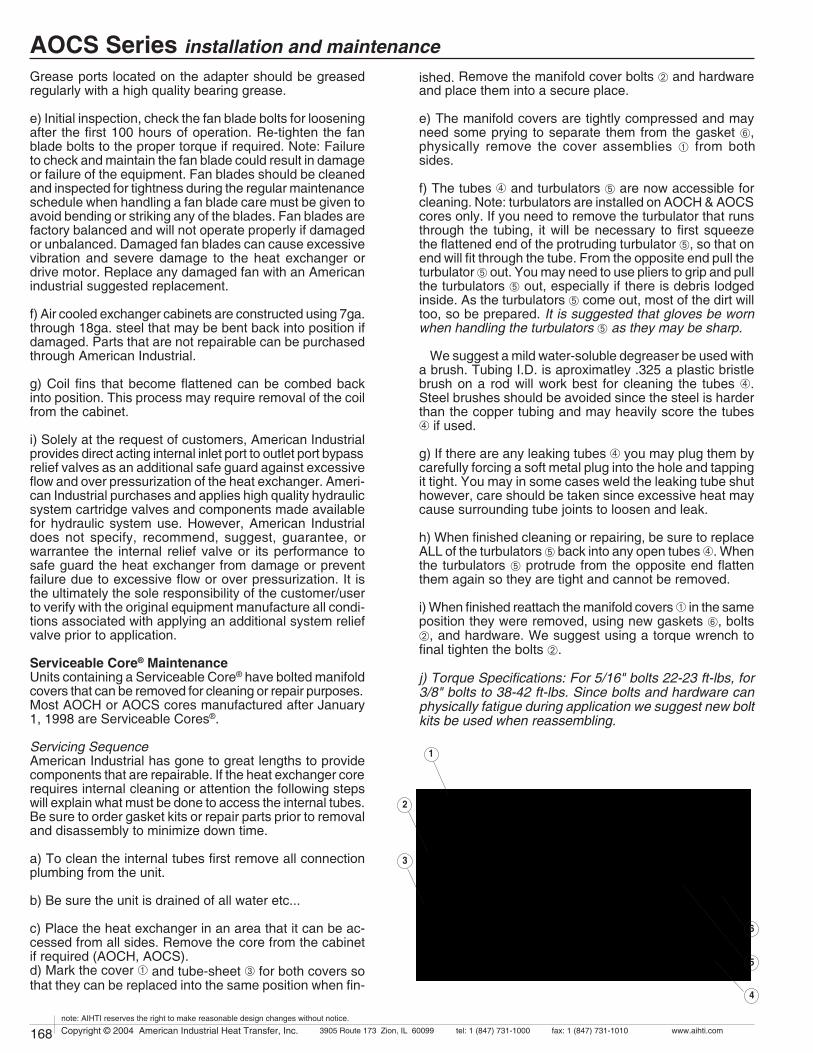
168 Copyright © 2004 American Industrial Heat Transfer, Inc. tel: 1 (847) 731-10003905 Route 173 Zion, IL 60099 www.aihti.comfax: 1 (847) 731-1010
note: AIHTI reserves the right to make reasonable design changes without notice.
169Copyright © 2004 American Industrial Heat Transfer, Inc. tel: 1 (847) 731-10003905 Route 173 Zion, IL 60099 www.aihti.comfax: 1 (847) 731-1010
note: AIHTI reserves the right to make reasonable design changes without notice.
AOCS Series installation and maintenanceGrease ports located on the adapter should be greased regularly with a high quality bearing grease.
e) Initial inspection, check the fan blade bolts for loosening after the first 100 hours of operation. Re-tighten the fan blade bolts to the proper torque if required. Note: Failure to check and maintain the fan blade could result in damage or failure of the equipment. Fan blades should be cleaned and inspected for tightness during the regular maintenance schedule when handling a fan blade care must be given to avoid bending or striking any of the blades. Fan blades are factory balanced and will not operate properly if damaged or unbalanced. Damaged fan blades can cause excessive vibration and severe damage to the heat exchanger or drive motor. Replace any damaged fan with an American industrial suggested replacement.
f) Air cooled exchanger cabinets are constructed using 7ga. through 18ga. steel that may be bent back into position if damaged. Parts that are not repairable can be purchased through American Industrial.
g) Coil fins that become flattened can be combed back into position. This process may require removal of the coil from the cabinet.
i) Solely at the request of customers, American Industrial provides direct acting internal inlet port to outlet port bypass relief valves as an additional safe guard against excessive flow and over pressurization of the heat exchanger. Ameri-can Industrial purchases and applies high quality hydraulic system cartridge valves and components made available for hydraulic system use. However, American Industrial does not specify, recommend, suggest, guarantee, or warrantee the internal relief valve or its performance to safe guard the heat exchanger from damage or prevent failure due to excessive flow or over pressurization. It is the ultimately the sole responsibility of the customer/user to verify with the original equipment manufacture all condi-tions associated with applying an additional system relief valve prior to application.
Serviceable Core® MaintenanceUnits containing a Serviceable Core® have bolted manifold covers that can be removed for cleaning or repair purposes. Most AOCH or AOCS cores manufactured after January 1, 1998 are Serviceable Cores®.
Servicing SequenceAmerican Industrial has gone to great lengths to provide components that are repairable. If the heat exchanger core requires internal cleaning or attention the following steps will explain what must be done to access the internal tubes. Be sure to order gasket kits or repair parts prior to removal and disassembly to minimize down time.
a) To clean the internal tubes first remove all connection plumbing from the unit.
b) Be sure the unit is drained of all water etc...
c) Place the heat exchanger in an area that it can be ac-cessed from all sides. Remove the core from the cabinet if required (AOCH, AOCS).d) Mark the cover À and tube-sheet  for both covers so that they can be replaced into the same position when fin-
ished. Remove the manifold cover bolts Á and hardware and place them into a secure place.
e) The manifold covers are tightly compressed and may need some prying to separate them from the gasket Å, physically remove the cover assemblies À from both sides.
f) The tubes à and turbulators Ä are now accessible for cleaning. Note: turbulators are installed on AOCH & AOCS cores only. If you need to remove the turbulator that runs through the tubing, it will be necessary to first squeeze the flattened end of the protruding turbulator Ä, so that on end will fit through the tube. From the opposite end pull the turbulator Ä out. You may need to use pliers to grip and pull the turbulators Ä out, especially if there is debris lodged inside. As the turbulators Ä come out, most of the dirt will too, so be prepared. It is suggested that gloves be worn when handling the turbulators Ä as they may be sharp.
We suggest a mild water-soluble degreaser be used with a brush. Tubing I.D. is aproximatley .325 a plastic bristle brush on a rod will work best for cleaning the tubes Ã. Steel brushes should be avoided since the steel is harder than the copper tubing and may heavily score the tubes à if used.
g) If there are any leaking tubes à you may plug them by carefully forcing a soft metal plug into the hole and tapping it tight. You may in some cases weld the leaking tube shut however, care should be taken since excessive heat may cause surrounding tube joints to loosen and leak.
h) When finished cleaning or repairing, be sure to replace ALL of the turbulators Ä back into any open tubes Ã. When the turbulators Ä protrude from the opposite end flatten them again so they are tight and cannot be removed.
i) When finished reattach the manifold covers À in the same position they were removed, using new gaskets Å, bolts Á, and hardware. We suggest using a torque wrench to final tighten the bolts Á.
j) Torque Specifications: For 5/16" bolts 22-23 ft-lbs, for 3/8" bolts to 38-42 ft-lbs. Since bolts and hardware can physically fatigue during application we suggest new bolt kits be used when reassembling.
1
2
3
4
6
5
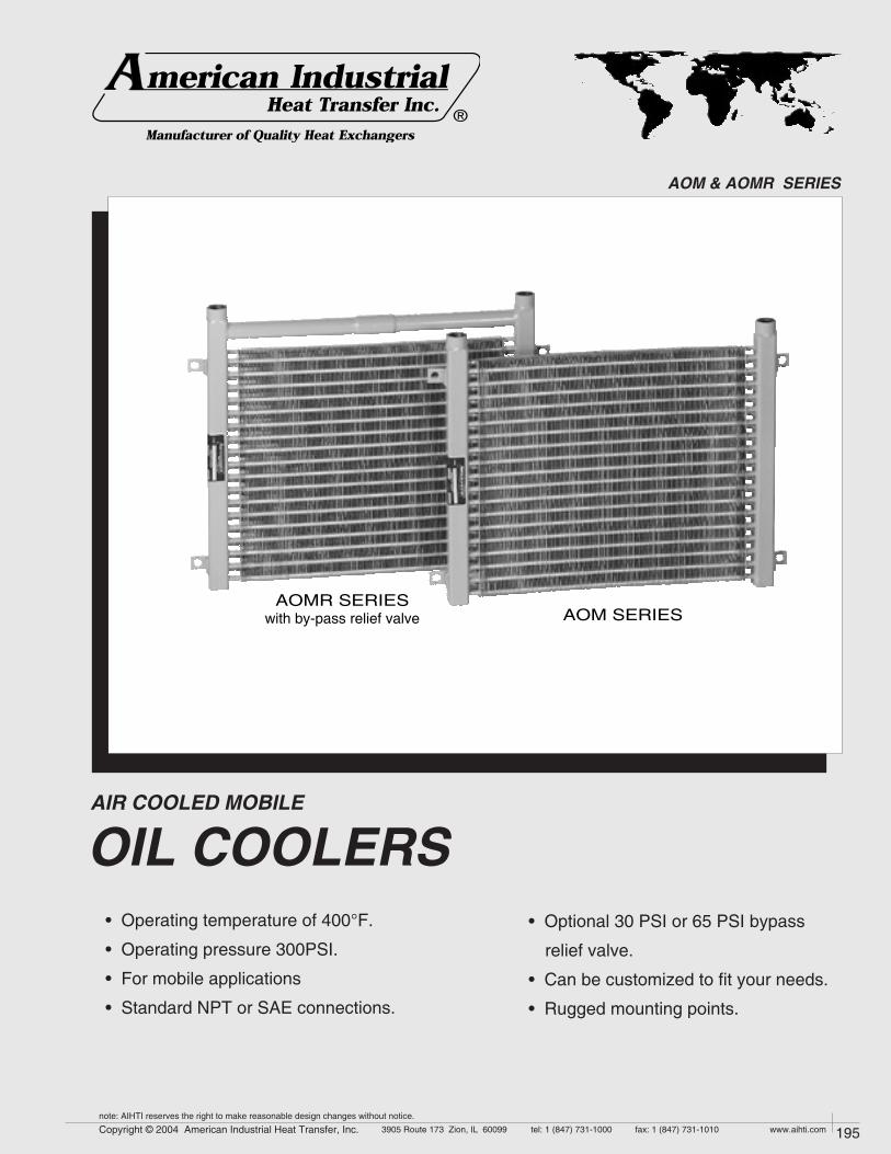
194 Copyright © 2004 American Industrial Heat Transfer, Inc. tel: 1 (847) 731-10003905 Route 173 Zion, IL 60099 www.aihti.comfax: 1 (847) 731-1010
note: AIHTI reserves the right to make reasonable design changes without notice.
195Copyright © 2004 American Industrial Heat Transfer, Inc. tel: 1 (847) 731-10003905 Route 173 Zion, IL 60099 www.aihti.comfax: 1 (847) 731-1010
note: AIHTI reserves the right to make reasonable design changes without notice.
AIR COOLED MOBILE
OIL COOLERS
AOM & AOMR SERIES
AOMR SERIESwith by-pass relief valve AOM SERIES
• Operating temperature of 400°F.
• Operating pressure 300PSI.
• For mobile applications
• Standard NPT or SAE connections.
®
• Optional 30 PSI or 65 PSI bypass
relief valve.
• Can be customized to fit your needs.
• Rugged mounting points.
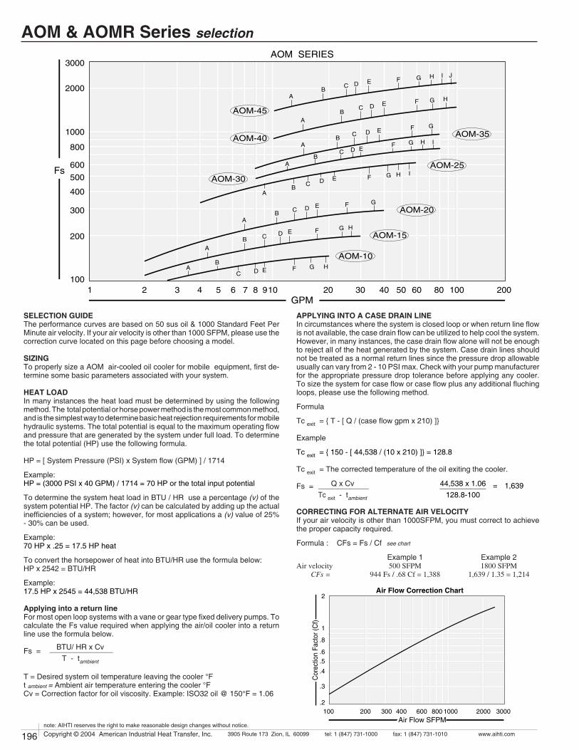
196 Copyright © 2004 American Industrial Heat Transfer, Inc. tel: 1 (847) 731-10003905 Route 173 Zion, IL 60099 www.aihti.comfax: 1 (847) 731-1010
note: AIHTI reserves the right to make reasonable design changes without notice.
197Copyright © 2004 American Industrial Heat Transfer, Inc. tel: 1 (847) 731-10003905 Route 173 Zion, IL 60099 www.aihti.comfax: 1 (847) 731-1010
note: AIHTI reserves the right to make reasonable design changes without notice.
Q x Cv ____________Tc exit - tambient
44,538 x 1.06 ___________ = 1,639 128.8-100
2
1
.8
.6
.4
.5
.3
200100 300 400 600 800 1000 2000 3000.2
Air Flow Correction Chart
Air Flow SFPM
Cor
ectio
n Fa
ctor
(Cf)
AOM-30
AOM-35AOM-40
AOM-45
AOM-10
AOM-15
AOM-20
AOM-25
3000
100
2000
1000
800
500
600
400
300
200
91 2 3 4 5 6 7 8 10 20 4030 50 60 80 200100
AOM SERIES
GPM
Fs
B
B
BC D E
A
A
AB
A
C
C
D
D
E
E
F
F
G
BA
C D E F G
BA
C D E F G H
BA
C D E F G H I J
G H
F G HEDC
F G H IEDC
BA
F G H I
SELECTION GUIDEThe performance curves are based on 50 sus oil & 1000 Standard Feet Per Minute air velocity. If your air velocity is other than 1000 SFPM, please use the correction curve located on this page before choosing a model.
SIZINGTo properly size a AOM air-cooled oil cooler for mobile equipment, first de-termine some basic parameters associated with your system.
HEAT LOADIn many instances the heat load must be determined by using the following method. The total potential or horse power method is the most common method, and is the simplest way to determine basic heat rejection requirements for mobile hydraulic systems. The total potential is equal to the maximum operating flow and pressure that are generated by the system under full load. To determine the total potential (HP) use the following formula.
HP = [ System Pressure (PSI) x System flow (GPM) ] / 1714
Example:HP = (3000 PSI x 40 GPM) / 1714 = 70 HP or the total input potential
To determine the system heat load in BTU / HR use a percentage (v) of the system potential HP. The factor (v) can be calculated by adding up the actual inefficiencies of a system; however, for most applications a (v) value of 25% - 30% can be used.
Example:70 HP x .25 = 17.5 HP heat
To convert the horsepower of heat into BTU/HR use the formula below:HP x 2542 = BTU/HR
Example:17.5 HP x 2545 = 44,538 BTU/HR
Applying into a return lineFor most open loop systems with a vane or gear type fixed delivery pumps. To calculate the Fs value required when applying the air/oil cooler into a return line use the formula below.
Fs =
T = Desired system oil temperature leaving the cooler °Ft ambient = Ambient air temperature entering the cooler °FCv = Correction factor for oil viscosity. Example: ISO32 oil @ 150°F = 1.06
APPLYING INTO A CASE DRAIN LINEIn circumstances where the system is closed loop or when return line flow is not available, the case drain flow can be utilized to help cool the system. However, in many instances, the case drain flow alone will not be enough to reject all of the heat generated by the system. Case drain lines should not be treated as a normal return lines since the pressure drop allowable usually can vary from 2 - 10 PSI max. Check with your pump manufacturer for the appropriate pressure drop tolerance before applying any cooler. To size the system for case flow or case flow plus any additional fluching loops, please use the following method.
Formula
Tc exit = { T - [ Q / (case flow gpm x 210) ]} Example
Tc exit = { 150 - [ 44,538 / (10 x 210) ]} = 128.8
Tc exit = The corrected temperature of the oil exiting the cooler.
Fs =
CORRECTING FOR ALTERNATE AIR VELOCITYIf your air velocity is other than 1000SFPM, you must correct to achieve the proper capacity required.
Formula : CFs = Fs / Cf
Example 1 Example 2Air velocity 500 SFPM 1800 SFPM CFs = 944 Fs / .68 Cf = 1,388 1,639 / 1.35 = 1,214
BTU/ HR x Cv _______________T - tambient
AOM & AOMR Series selection
see chart

196 Copyright © 2004 American Industrial Heat Transfer, Inc. tel: 1 (847) 731-10003905 Route 173 Zion, IL 60099 www.aihti.comfax: 1 (847) 731-1010
note: AIHTI reserves the right to make reasonable design changes without notice.
197Copyright © 2004 American Industrial Heat Transfer, Inc. tel: 1 (847) 731-10003905 Route 173 Zion, IL 60099 www.aihti.comfax: 1 (847) 731-1010
note: AIHTI reserves the right to make reasonable design changes without notice.
EXAMPLE OF A MODEL
AOM & AOMR DIMENSIONS & WEIGHTS
C
D
E
F
G*
1.50.5 MountingHoles 4 Places
BA H
By-Pass Check Valve
Return LineFs = 1,388
GPM = 40 "return line flow"Model = AOM - 45
Case LineFs = 1,214GPM = 10
Model = AOM - 45
SELECTIONTo select a model, locate the flow rate (GPM) through the cooler at the bot-tom of the flow vs Fs graph. Proceed upward until the GPM intersects with the calculated Fs. The curve closest above the intersection point will meet these conditions.
Examples:
PRESSURE DROPDetermine the oil pressure drop from the curves as indicated. For viscosi-ties other than 50 sus at operating, multiply the actual indicated pressure drop (psi) for your GPM by the value in the pressure differential chart for your viscosity.
Examples: GPM = 40 GPM = 10
Indicated pressure drop 5 PSI 1 PSICp correction factor forISO 32 oil @ 150°F 1.17 1.17
AOM - 25 - N
ModelSize
Connections
N = NPTS = SAE
Model Face AreaF HSAE
HNPT
DCBA E
STANDARD DIMENSIONS (inches)
AOM & AOMR-10-#
AOM & AOMR-15-#
AOM & AOMR-20-#
AOM & AOMR-25-#
AOM & AOMR-30-#
AOM & AOMR-35-#
AOM & AOMR-40-#
AOM & AOMR-45-#
18.22
18.22
18.22
24.22
23.22
23.22
28.72
39.22
16.72
16.72
16.72
22.72
21.72
21.72
27.22
37.72
19.72
19.72
19.72
25.72
24.72
24.72
30.22
40.72
3.50
5.50
9.50
15.50
21.50
27.50
33.50
33.50
13.72
13.72
13.72
19.72
18.72
18.72
24.22
34.72
1.00
1.00
1.00
1.00
1.25
1.25
1.25
1.25
16 SAE1-5/16-12
UN-2B
20 SAE1-5/8-12 UN-2B
6.00
8.00
12.00
18.00
24.00
30.00
36.00
36.00
.60
.81
1.21
2.56
3.25
1.06
6.25
8.88
WeightLBS
20
25
35
40
45
55
65
75
GAOM
8.62
10.62
14.62
20.62
26.56
32.56
38.31
38.31
10.06
12.06
16.06
22.06
28.06
34.06
40.38
40.38
GAOMR
AOMR - 25 - S - R - 65
ModelSize Connections Relief
ValveN = NPTS = SAE
PSI Relief
30 = 30psi65 = 65psi
AOM & AOMR Series dimensions
]Represents desired fluid leaving the cooler.
Horsepower to be removed (HP) x 2545 x Cv °F (Oil Leaving] - Ambient Air Entering) Fs =
OIL PRESSURE DROP (PSI) CODE
BTUhr °F
=
PERFORMANCE CALCULATIOND = 4 PSIE = 5 PSIF = 10 PSI
G = 15 PSIH = 20 PSI I = 25 PSI
J = 30 PSIA = 1 PSIB = 2 PSIC = 3 PSI
OUT
IN
AOMIN or OUT
AOMRINLET ONLY
AOMIN or OUT

198 Copyright © 2004 American Industrial Heat Transfer, Inc. tel: 1 (847) 731-10003905 Route 173 Zion, IL 60099 www.aihti.comfax: 1 (847) 731-1010
note: AIHTI reserves the right to make reasonable design changes without notice.
199Copyright © 2004 American Industrial Heat Transfer, Inc. tel: 1 (847) 731-10003905 Route 173 Zion, IL 60099 www.aihti.comfax: 1 (847) 731-1010
note: AIHTI reserves the right to make reasonable design changes without notice.
AOM & AOMR Series installation & maintenanceReceiving / Installationa) Inspect unit for any shipping damage before uncrating. Indicate all damages to the trucking firms' delivery person and mark it on the receiving bill before accepting the freight. Make sure that the core and fan are not damaged. Rotate the fan blade to make sure that it moves freely. Since the warranty is based upon the unit date code located on the model identification tag, removal or manipulation of the identification tag will void the manufacturers warranty.
c) Standard Enamel Coating: American Industrial provides its standard products with a normal base coat of oil base air cure enamel paint. The enamel paint is applied as a temporary protective and esthetic coating prior to shipment. While the standard enamel coating is durable, American Industrial does not warranty it as a long-term finish coating. It is strongly suggested that a more durable final coating be applied after installation or prior to long-term storage in a corrosive environment to cover any accidental scratches, enhance esthetics, and further prevent corrosion. It is the responsibility of the customer to provide regular maintenance against chips, scratches, etc... and regular touch up maintenance must be provided for long-term benefits and corrosion prevention.
d) Special Coatings: American Industrial offers as customer options, Air-Dry Epoxy, and Heresite (Air-Dry Phenolic) coatings at additional cost. American Industrial offers special coatings upon request, however American Industrial does not warrantee coatings to be a permanent solution for any equipment against corrosion. It is the responsibility of the customer to provide regular maintenance against chips, scratches, etc... and regular touch up maintenance must be provided for long-term benefits and corrosion prevention.
e) American Industrial recommends that the equipment supplied should be installed by qualified personnel who have solid understanding of system design, pressure and temperature ratings, and piping assembly. Verify the service conditions of the system prior to applying any air cooled heat exchanger series cooler. If the system pressure or temperature does not fall within the parameters on model rating tag located on the heat exchanger, contact our factory prior to installation or operation.
g) Heat exchanger should be securely fastened using the mounting foot brackets (included). All mounting holes should be used to secure unit into place.
h) Connections should be made in "one pass" or "two pass" configurations exactly as indicated in the "piping hook up" illustration. The process flow entering the "Fluid IN" port and exiting the "Fluid OUT" port eliminates air pockets and assures that the unit will stay completely flooded. Flexible hose can be applied to reduce the risk of core failure due to thermal ex-pansion or system vibration. Piping alignment and support is required for hoses longer than four feet in length and for piping exerting more than 10 lbs of dynamic force. It is recommended that filtration be located ahead of the heat exchanger to prevent excessive backpressure and clogging.
i) With respect to the heat exchangers nozzle size, flow line sizes should be sized to handle the appropriate flow rate and system pressure drop requirements, normally flow line rates of about 8-12 feet per second and inlet pressure less than 100psig are experienced. If the flow line size is larger than the heat exchanger nozzle size, additional pressure loss beyond the published pressure loss data may occur.
j) Electric motors should be connected only to supply source of the same characteristics as indicated on the electric motor information plate. Prior to starting, verify that the motor and fan spin freely without obstruction. Check carefully that the fan turns in the correct rotation direction (normally counter clockwise) from the motor side (fan direction arrow). Failure to operate the fan in the proper direction could reduce performance or cause serious damage to the heat exchanger or other components.
k) Solely at the request of customers, American Industrial provides direct acting internal inlet port to outlet port bypass relief valves as an addi-tional safe guard against excessive flow and over pressurization of the heat exchanger. American Industrial purchases and applies high quality hydraulic system cartridge valves and components made available for hydraulic system use. However, American Industrial does not specify, recommend, suggest, guarantee, or warrantee the internal relief valve or its performance to safe guard the heat exchanger from damage or prevent failure due to excessive flow or over pressurization. It is the ultimately the sole responsibility of the customer/user to verify with the original equipment manufacture all conditions associated with applying an additional system relief valve prior to application.
MaintenanceRegular maintenance intervals based upon the surrounding and opera-tional conditions should be maintained to verify equipment performance and to prevent premature component failure. Since some of the compo-nents such as, motors, fans, etc... are not manufactured by American Industrial, maintenance requirements provided by the manufacture must be followed.
a) Inspect the entire heat exchanger and motor/fan assembly for loosened bolts, loose connections, broken components, rust spots, corrosion, fin/coil clogging, or external leakage. Make immediate repairs to all affected areas prior to restarting and operating the heat exchanger or its components.
b) Heat exchangers operating in oily or dusty environments will often need to have the coil cooling fins cleaned. Oily or clogged fins should be cleaned by carefully brushing the fins and tubes with water or a non-ag-gressive degreasing agent mixture (Note: Cleaning agents that are not compatible with copper, brass, aluminum, steel or stainless steel should not be used). A compressed air or a water stream can be used to dislodge dirt and clean the coil further. Any external dirt or oil on the electric motor and fan assembly should be removed. Caution: Be sure to disconnect the electric motor from its power source prior to doing any maintenance.
c) In most cases it is not necessary to internally flush the coil. In circum-stances where the coil has become plugged or has a substantial buildup of material, flushing the coil with water or a solvent may be done. Flush-ing solvents should be non-aggressive suitable for the materials of con-struction. Serviceable Core® models can be disassembled and inspected or cleaned if required.
e) Fan blades should be cleaned and inspected for tightness during the regular maintenance schedule when handling a fan blade care must be given to avoid bending or striking any of the blades. Fan blades are fac-tory balanced and will not operate properly if damaged or unbalanced. Damaged fan blades can cause excessive vibration and severe damage to the heat exchanger or drive motor. Replace any damaged fan with an American industrial suggested replacement.
f) Air cooled exchanger cabinets are constructed using 7ga. through 18ga. steel that may be bent back into position if damaged. Parts that are not repairable can be purchased through American Industrial.
g) Coil fins that become flattened can be combed back into position. This process may require removal of the coil from the cabinet.
h) It is not advisable to attempt repairs to brazed joints of a brazed construction coil unless it will be done by an expert in silver solder braz-ing. Brazed coils are heated uniformly during the original manufacturing process to prevent weak zones from occurring. Uncontrolled reheating of the coil may result in weakening of the tube joints surrounding the repair area. In many instances brazed units that are repaired will not hold up as well to the rigors of the system as will a new coil. American Industrial will not warranty or be responsible for any repairs done by unauthorized sources. Manipulation in any way other than normal application will void the manufactures warranty.

168 Copyright © 2004 American Industrial Heat Transfer, Inc. tel: 1 (847) 731-10003905 Route 173 Zion, IL 60099 www.aihti.comfax: 1 (847) 731-1010
note: AIHTI reserves the right to make reasonable design changes without notice.
169Copyright © 2004 American Industrial Heat Transfer, Inc. tel: 1 (847) 731-10003905 Route 173 Zion, IL 60099 www.aihti.comfax: 1 (847) 731-1010
note: AIHTI reserves the right to make reasonable design changes without notice.
EOC SERIES
• Standard NPT or SAE models in stock.
• AC - DC or hydraulic fan drives.
• High quality serviceable air filter.
• Operating temperature of 300oF & pres-
sure of 300 PSI.
• Can be customized to fit your needs.
OIL COOLERS
INDUSTRIAL & MOBILE AIR COOLED
®
• Adjustable mounting brackets included for
easy installation.
• Cools: fluid power systems, injection
molding machines, hydraulic presses,
gear drives, torque convertors, machine
tools, etc...

170 Copyright © 2004 American Industrial Heat Transfer, Inc. tel: 1 (847) 731-10003905 Route 173 Zion, IL 60099 www.aihti.comfax: 1 (847) 731-1010
note: AIHTI reserves the right to make reasonable design changes without notice.
171Copyright © 2004 American Industrial Heat Transfer, Inc. tel: 1 (847) 731-10003905 Route 173 Zion, IL 60099 www.aihti.comfax: 1 (847) 731-1010
note: AIHTI reserves the right to make reasonable design changes without notice.
EOC Series overview
EOC & EOCF with hydraulic drive Mobile & industrial air-cooled oil coolers. Brazed or
serviceable core ®, mobile and industrial series heat exchang-
ers available with optional washable filter and integral relief
valve, 30 PSI or 65 PSI. Standard hydraulic drive motor(s)
with single or dual cooling fans. Rated operating temperature
of 400oF at 300 PSIG. Standard flow rates to 180 GPM.
Thermal capacity up to 225 hp (168 Kw). N PT or SAE strait
thread O-ring port connections. Can be modified to meet your
requirements. Suitable for most hydraulic oils, lubrication oils,
synthetic compressor oils, ethylene glycol, and many other
fluids compatible with listed materials.
EOC & EOCF with electric drive Mobile & industrial air-cooled oil coolers. Brazed
or serviceable core ®, mobile and industrial series heat ex-
changers available with optional washable filter and integral
relief valve, 30 PSI or 65 PSI. Standard single phase, three
phase, 12 volt DC (21amp) or 24 volt DC (10.5 amp) motors
with single or dual cooling fans. Rated operating temperature
of 400oF at 300 PSIG. Standard flow rates to 180 GPM.
Thermal capacity up to 225 hp (168 Kw). N PT or SAE strait
thread O-ring port connections. Can be modified to meet your
requirements. Suitable for most hydraulic oils, lubrication oils,
synthetic compressor oils, ethylene glycol, and many other
fluids compatible with listed materials.
EOC 190 thru EOC 337EOC 375 thru EOC 700
washablefilter

170 Copyright © 2004 American Industrial Heat Transfer, Inc. tel: 1 (847) 731-10003905 Route 173 Zion, IL 60099 www.aihti.comfax: 1 (847) 731-1010
note: AIHTI reserves the right to make reasonable design changes without notice.
171Copyright © 2004 American Industrial Heat Transfer, Inc. tel: 1 (847) 731-10003905 Route 173 Zion, IL 60099 www.aihti.comfax: 1 (847) 731-1010
note: AIHTI reserves the right to make reasonable design changes without notice.
EOC Series construction
HIGH PERFORMANCE TURBULATOR Exclusive American Industrial Turbulators (installed in
every flow tube) increase heat transfer by more than 100%.
American Industrial Turbulators eliminate the laminar flow
condition normally associated with other smooth tube heat
exchangers. High viscosity hydraulic and lubricating oils are
easily cooled by this new state-of-the-art turbulator.
TANKS EOC-190 - EOC-575
State-of-the-art 21st century high temperature brazing
method insures permanent bond and positive contact of
tube to manifold, eliminating leaks and providing maximum
service life.
CONSTRUCTION MATERIALS & RATINGS
Tubes Copper
Fins Aluminum
Turbulators Steel
Tank Steel
Connection pipes Steel
Cabinet & frame Steel
Fan Blade Aluminum with steel hub
Fan Guard Zinc plated steel
Operating Pressure 300 psig
Operating Temperature 300 oF
Max. Flow Internal Relief 38 gpm
Max. Fan Over-speed 10 %
Max. Ambient Conditions 104 oF
Altitude 0-3300 ft.
Carbon Steel
Copper
Brass
Brass
Brass
316L Stainless Steel, Galvanized Steel
Plastic, Non-sparking
Zinc plated steel
Standard Construction Materials Optional Construction Materials Standard Unit Ratings
SERVICEABLE CORE ® EOC-700 only
Core covers disassemble for easy access and clean-
ing. Repairable design for applications that require limited
down time. Roller expanded tube to tube-sheet joint.
100% mechanical bond. Positive gasket seal is field
replaceable for field maintenance or repair.

172 Copyright © 2004 American Industrial Heat Transfer, Inc. tel: 1 (847) 731-10003905 Route 173 Zion, IL 60099 www.aihti.comfax: 1 (847) 731-1010
note: AIHTI reserves the right to make reasonable design changes without notice.
173Copyright © 2004 American Industrial Heat Transfer, Inc. tel: 1 (847) 731-10003905 Route 173 Zion, IL 60099 www.aihti.comfax: 1 (847) 731-1010
note: AIHTI reserves the right to make reasonable design changes without notice.
100
1000
10000
1 10 100 3002 3 4 5 6 7 8 9 20 30 40 50 60 80 200
200
300400500600
800
2000
30004000500060008000
EOC-190
EOC-220
EOC-249
EOC-337EOC-375
EOC-505
EOC-545EOC-575
EOC-700
ACB D E F IHG J
ACB D E F HG
B D E F G H I J
AB C D
C
E F G H J
ACB
D E F G
ACB
D E F
ACB
D E F
AB C D E
GPM
Fs
EOC - 1PASS SERIES
A
CBD E F HG
Example Line
200
100
1000
10000
300400500
600800
2000
3000
4000
6000
8000
1 10 1002 3 4 5 6 7 8 9 20 30 40 50 60 80
CB D E F IHG J
CB D E F IHG J
B D E F G H I JC
AB C D E F G H J
ACB D E F IHG J
A
CB
D E F IHG
ACB
D E F IHG
AB C D E F EOC-190
EOC-220
EOC-249
EOC-337
EOC-375EOC-505
EOC-545EOC-575
EOC-700
GPM
Fs
EOC - 2PASS SERIES
ACB D E F IHG J K
Horsepower to be removed (HP) x 2545 x Cv °F (Oil Leaving] - Ambient Air Entering) Fs =
OIL PRESSURE DROP (PSI) CODE
BTUhr °F
=
Note: When a model selection has been made, record whether the selection was from the one pass curve or the two pass curve so that the unit can be properly plumbed. Incorrect installation can seriously affect the performance.
PERFORMANCE CALCULATION
]Represents desired fluid leaving the cooler.
D = 4 PSIE = 5 PSIF = 10 PSI
G = 15 PSIH = 20 PSI I = 25 PSI
J = 30 PSIK = 35 PSI
A = 1 PSIB = 2 PSIC = 3 PSI
EOC Series performance
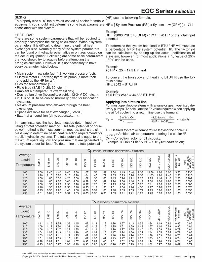
172 Copyright © 2004 American Industrial Heat Transfer, Inc. tel: 1 (847) 731-10003905 Route 173 Zion, IL 60099 www.aihti.comfax: 1 (847) 731-1010
note: AIHTI reserves the right to make reasonable design changes without notice.
173Copyright © 2004 American Industrial Heat Transfer, Inc. tel: 1 (847) 731-10003905 Route 173 Zion, IL 60099 www.aihti.comfax: 1 (847) 731-1010
note: AIHTI reserves the right to make reasonable design changes without notice.
EOC Series selection
Cp PRESSURE DROP CORRECTION FACTORS
ISO
22
SA
E 3
0
SA
E 1
0
SA
E 5
6.405.104.203.402.902.501.400.97
4.403.603.002.602.231.901.200.92
2.402.101.801.601.501.300.960.82
8.806.705.604.503.703.101.601.05
2.001.701.501.401.301.200.930.81
50%
ETH
YLE
NE
GLY
CO
L&
WA
TER
POLY
GLY
CO
L3.002.402.101.901.901.701.201.00
PHO
SPH
ATE
ESTE
R
3.502.902.502.202.001.901.301.05
0.7300.7200.7090.6980.6860.6760.6350.556
AverageLiquid
Temperature
100110120130140150200250
ISO
32
1.071.041.020.990.970.950.890.85
ISO
46
1.531.451.381.301.231.170.990.93
ISO
68
1.821.721.601.491.381.301.080.96
ISO
100
2.542.352.151.941.751.611.181.03
ISO
150
4.193.733.262.802.382.041.331.11
ISO
220
6.445.704.914.143.472.901.591.21
ISO
320
9.388.337.236.195.204.351.741.22
SA
E 4
0
MIL
-L-7
808
1.261.201.141.081.030.980.900.83
SA
E 2
0
13.5611.63 9.73 7.80 6.11 4.77 1.95 1.23
Cv VISCOSITY CORRECTION FACTORS
ISO
22
SA
E 3
0
SA
E 1
0
SA
E 5
1.381.321.271.241.191.161.040.98
1.251.201.171.131.111.091.010.97
1.151.121.101.081.051.040.990.96
1.451.401.351.291.251.221.070.99
1.111.091.061.041.031.010.980.95
50%
ETH
YLE
NE
GLY
CO
L&
WA
TER
POLY
GLY
CO
L
0.920.890.880.850.840.830.790.76
PHO
SPH
ATE
ES
TER
0.830.800.790.770.760.740.710.69
0.850.840.840.830.820.820.800.79
AverageLiquid
Temperature
100110120130140150200250
ISO
32
1.081.061.041.031.021.020.980.95
ISO
46
1.141.131.111.091.081.060.990.96
ISO
68
1.181.161.141.131.101.091.000.96
ISO
100
1.261.251.201.171.161.131.010.96
ISO
150
1.371.311.271.241.201.171.020.97
ISO
220
1.431.391.351.301.261.221.080.99
ISO
320
1.561.481.401.341.301.271.091.01
SA
E 4
0
MIL
-L-7
808
1.191.141.091.051.031.010.980.97
SA
E 2
0
1.841.671.531.441.391.331.141.02
SIZINGTo properly size a DC fan drive air-cooled oil cooler for mobile equipment, you should first determine some basic parameters associated with the system.
HEAT LOADThere are some system parameters that will be required toproperly accomplish the sizing calculations. Without systemparameters, it is difficult to determine the optimal heatexchanger size. Normally many of the system parameterscan be found on hydraulic schematics or on tags located onthe actual equipment. Following are some basic param-etersthat you should try to acquire before attempting thesizing calculations. However, it is not necessary to haveevery parameter listed below.
• Main system flow rate (gpm) & working pressure (psi).• Electric motor HP driving hydraulic pump (if more than one add up the HP for all).• Desired temperature (°F).• Fluid type (SAE 10, 20, 30, etc....).• Ambient air temperature (warmest day).• Desired fan drive (hydraulic, electric, 12-24V DC, etc...).• BTU’s or HP to be cooled (normally given for lubrication systems).• Maximum pressure drop allowed through the heat exchanger.• Space available for heat exchanger (LxWxH).• External air condition (dirty, papers,etc…).
In many instances the heat load must be determined by using a “total potential” method. This total potential or horse power method is the most common method, and is the sim-plest way to determine basic heat rejection requirements for mobile hydraulic systems. The total potential is equal to the maximum operating flow and pressure that are generated by the system under full load. To determine the total potential
Btu/ hr x Cv ____________T - tambient
44,538Btu/hr x 1.13Cv ________________140oF - 100oFambient
= 1258 Fs
(HP) use the following formula.
HP = [ System Pressure (PSI) x System flow (GPM) ] / 1714
Example:HP = (3000 PSI x 40 GPM) / 1714 = 70 HP or the total input potential
To determine the system heat load in BTU / HR we must use a percentage (v) of the system potential HP. The factor (v) can be calculated by adding up the actual inefficiencies of a system; however, for most applications a (v) value of 25% - 30% can be used.
Example:70 HP x .25 = 17.5 HP heat
To convert the horsepower of heat into BTU/HR use the for-mula below:HP x 2542 = BTU/HR
Example:17.5 HP x 2545 = 44,538 BTU/HR
Applying into a return lineFor most open loop systems with a vane or gear type fixed de-livery pumps. To calculate the Fs value required when applying the air/oil cooler into a return line use the formula.
Fs =
T = Desired system oil temperature leaving the cooler °Ftambient = Ambient air temperature entering the cooler °FCv = Correction factor for oil viscosity. Example: ISO68 oil @ 150°F = 1.13 (see chart below)

174 Copyright © 2004 American Industrial Heat Transfer, Inc. tel: 1 (847) 731-10003905 Route 173 Zion, IL 60099 www.aihti.comfax: 1 (847) 731-1010
note: AIHTI reserves the right to make reasonable design changes without notice.
175Copyright © 2004 American Industrial Heat Transfer, Inc. tel: 1 (847) 731-10003905 Route 173 Zion, IL 60099 www.aihti.comfax: 1 (847) 731-1010
note: AIHTI reserves the right to make reasonable design changes without notice.
EOC Series selection
= 2,869.9 FsFs =
Fs =
Return LineFs = 1,258GPM = 40 "return flow"Model = EOC-375-4
Case LineFs = 2,142GPM = 8 "case flow"Model = EOC-575-4-2P
Recirculation LoopFs = 2,869.9GPM = 15 "loop flow"Model = EOC-575-3-2P
APPLYING INTO A CASE DRAIN LINEIn circumstances where the system is a closed loop or when return line flow is not available, the case drain flow can be utilized to help cool the system However, in many instances, the case drain flow alone will not be enough to reject all of the heat generated by the system. Case drain lines should not be treated as a normal return lines since the pressure drop allowable usually can vary from 2-10 PSI max. Check with your pump manufacturer for the appropriate pressure drop tolerance before applying any cooler. To size the sys-tem for case flow or case flow plus any additional flushing loops, please use the following method.
Formula:Tc exit = The corrected temperature of the oil exiting the cooler.
Tc exit = { T - [ Q / (case flow gpm x 210) ]} Example:Tc exit = { 150 - [ 44,538 / (8 x 210) ]} = 123.5
Fs =
Re-circulation Cooling Application (Kidney Loop)When applying any American Industrial air-cooled heat exchanger into a re-circulation (filtration loop) some important differences should be noted. The standard air-cooled heat transfer calculation can be used however some preliminary calculations must be done prior to using the formula. Before applying the standard air-cooled heat transfer formula, the air oil cooler exiting temperature must be derived from.
Example Re-circulation Loop Application Fluid - Oil SAE 5wFlow - 15 GPM re-circulatingDesired Reservoir Temp - 125oFAmbient Temp - 90oFInput potential 60 HPHeat to be removed 1/3 x 60HP = 20HPFan drive requirements 3/60/230-460 motor.
= 16.6oFrT =
rT =
Q x Cv ____________Tc exit - tambient
44,538Btu/hr x 1.13Cv ________________ = 2,142 123.5oF-100oF
Step 1Formula 1
Example 20HP x 2545 15gpm x 210 Step 2Formula 2 HP(to be removed) x 2545 x CV (T1-rT) - Ambient oF
Example 220HP x 2545 x 1.06 (125-16.2) - 90oF
Step 3Selection from the heat energy dissipation chart (page 172.) EOC-575-3-2PSee example line 2pass curve.
SELECTIONTo select a model, locate the flow rate (GPM) at the bot-tom of the flow vs Fs graph. Proceed upward until the GPM intersects with the calculated Fs. The curve closest above the intersection point will meet these conditions. Examples:
PRESSURE DROPDetermine the oil pressure drop from the curves as indicated. For viscosities other than 50 ssu, multiply the actual indicated pressure drop (psi) for your GPM by the Cp value in the pressure differential curve for your viscosity value.
Examples: EOC-375 EOC-575-2P @GPM = 40 @GPM = 8
Indicated pressure drop 7.8 PSI 4 PSICp correction factor (pg.173) 1.61 1.45Corrected Pressure drop 12.56 PSI 5.8 PSI
EOC - 337 - 1 - __ - S - R65 - ____ - ____
EOC = standardEOCF = with washable filter Size
Connection Typeblank = NPT
S = SAE
blank = no motor1 = single phase1EXP = explosion proof3 = three phase3EXP = explosion proof5 = 575 volt4 = 12v DC6 = 24v DC9 = hydraulic
R65 = 65psiR30 = 30psi
Model
Motor
Coatingblank = Enamel (standard)G = Galvanize (cabinet)T = Heresite (core)X = Epoxy (cabinet)
Tubingblank = CopperC = Carbon Steel
Bypass*blank = one pass2P = two pass
Passes
*EOC-190 thru EOC-575 series releif valve available only on one pass unit. EOC-700 series relief valve available only on two pass unit.
EXAMPLE OF A MODEL
HP (to be removed) x 2545 Loop Flow (GPM)

174 Copyright © 2004 American Industrial Heat Transfer, Inc. tel: 1 (847) 731-10003905 Route 173 Zion, IL 60099 www.aihti.comfax: 1 (847) 731-1010
note: AIHTI reserves the right to make reasonable design changes without notice.
175Copyright © 2004 American Industrial Heat Transfer, Inc. tel: 1 (847) 731-10003905 Route 173 Zion, IL 60099 www.aihti.comfax: 1 (847) 731-1010
note: AIHTI reserves the right to make reasonable design changes without notice.
MODEL EOC - 190 Through EOC - 337
* Dimension used only with two pass units
EOC & EOCF Series dimensions with electric drive
M
A
Q
R.41 x 1.19
slot
2 Pass Only
S*
D
GH
Optional Filter Screen
E
B
Drain3/8" NPT
L
J
C
Port1/2" NPT
Note: opposite
side on two pass.
Fan
ro
tation
Air Flow
(TOP VIEW)
M
A
Q
C (APPROX)
R
Adjustment.41 x 1.57
S*
D
GH
Optional Filter Screen
E
B
P
.56 x .75 slot
G
H
Drain3/8" NPT
L
J
Port1/2" NPT
Note: opposite
side on two pass.
Fan
ro
tation
Fan
ro
tation
Air Flow
Male NPT portEOC-700 Only
MODEL EOC - 375 Through EOC - 700
COMMON DIMENSIONSModel A B C D
NPTD
SAE E G H J1/2-13 tab L M P Q R S*
EOC - 190 - Ý 13.62 16.50 14.21 .75 #12 14.75 5.00 2.61
(4)
8.00 15.00 10.31 11.38 10.38 7.65
EOC - 220 - Ý 15.62 22.00 16.32 .75 #12 18.69 5.00 2.61 14.00 20.50 12.31 16.88 12.25 10.25
EOC - 249 - Ý 19.62 24.75 16.32 .75 #12 21.44 5.00 2.61 14.00 23.25 16.31 20.00 16.25 15.00
EOC - 337 - Ý 25.62 30.25 16.32 1.00 #16 26.97 5.00 2.61 21.25 28.75 22.31 25.00 22.38 19.38
EOC - 375 - Ý 18.50 39.00 17.75 1.25 #20 40.50 6.50 1.06 30.00 36.50 15.25 33.00 15.13 12.50
EOC - 505 - Ý 22.50 41.0 17.13 1.25 #20 42.50 6.50 1.12 30.00 38.50 19.25 34.75 19.63 16.50
EOC - 545 - Ý 30.50 42.00 17.32 1.50 #24 43.75 9.00 1.71 30.00 39.50 27.25 35.75 27.50 24.63
EOC - 575 - Ý 36.50 48.00 17.32 2.00 #32 49.75 9.00 1.71 36.00 45.50 32.75 41.75 33.50 29.25
EOC - 700 - Ý 38.38 51.00 21.23 2.00† #32 52.75 9.00 1.62 (8) – 48.50 34.00 43.50 34.50 32.50
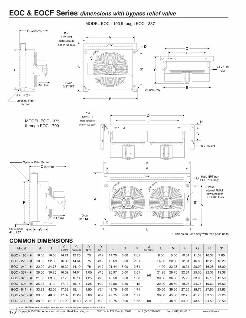
176 Copyright © 2004 American Industrial Heat Transfer, Inc. tel: 1 (847) 731-10003905 Route 173 Zion, IL 60099 www.aihti.comfax: 1 (847) 731-1010
note: AIHTI reserves the right to make reasonable design changes without notice.
177Copyright © 2004 American Industrial Heat Transfer, Inc. tel: 1 (847) 731-10003905 Route 173 Zion, IL 60099 www.aihti.comfax: 1 (847) 731-1010
note: AIHTI reserves the right to make reasonable design changes without notice.
EOC & EOCF Series dimensions with bypass relief valve
Air Flow
M
AC
C (APPROX)
R
D
GHB
Drain3/8" NPT
S*
2 Pass Only
QL
J
.41 x 1.19 slot
E
Optional Filter Screen
Port1/2" NPT
Note: opposite
side on two pass.
Fan
ro
tation
M
A
C (APPROX)
R
Adjustment.41 x 1.57
S*
D
Drain3/8" NPT
GH
Optional Filter Screen
E
B
P
.56 x .75 slot
G
H
2 PassInternal ReliefFlow DirectionEOC-700 Only
Port1/2" NPT
Note: opposite
side on two pass.
Fan
ro
tation
Fan
ro
tation
Male NPT portEOC-700 Only
Air Flow
Q
L
J
MODEL EOC - 375 through EOC - 700
MODEL EOC - 190 through EOC - 337
COMMON DIMENSIONS* Dimension used only with two pass units
Model A B Celectric
Chydraulic
DNPT
DSAE E G H J
1/2-13 tabL M P Q R S*
EOC - 190 - Ý 16.00 16.50 14.21 12.20 .75 #12 14.75 5.00 2.61
(4)
8.00 15.00 10.31 11.38 10.38 7.65
EOC - 220 - Ý 18.00 22.00 16.32 14.64 .75 #12 18.69 5.00 2.61 14.00 20.50 12.31 16.88 12.25 10.25
EOC - 249 - Ý 22.00 24.75 16.32 14.19 .75 #12 21.44 5.00 2.61 14.00 23.25 16.31 20.00 16.25 15.00
EOC - 337 - Ý 28.00 30.25 16.32 14.64 1.00 #16 26.97 5.00 2.61 21.25 28.75 22.31 25.00 22.38 19.38
EOC - 375 - Ý 21.38 39.00 17.75 15.14 1.25 #20 40.50 6.50 1.06 30.00 36.50 15.25 33.00 15.13 12.50
EOC - 505 - Ý 25.38 41.0 17.13 15.14 1.25 #20 42.50 6.50 1.12 30.00 38.50 19.25 34.75 19.63 16.50
EOC - 545 - Ý 33.28 42.00 17.32 15.14 1.50 #24 43.75 9.00 1.71 30.00 39.50 27.25 35.75 27.50 24.63
EOC - 575 - Ý 39.38 48.00 17.32 15.29 2.00 #32 49.75 9.00 1.71 36.00 45.50 32.75 41.75 33.50 29.25
EOC - 700 - Ý 38.39 51.00 21.23 15.40 2.00† #32 52.75 9.00 1.62 (8) – 48.50 34.00 43.50 34.50 32.50

176 Copyright © 2004 American Industrial Heat Transfer, Inc. tel: 1 (847) 731-10003905 Route 173 Zion, IL 60099 www.aihti.comfax: 1 (847) 731-1010
note: AIHTI reserves the right to make reasonable design changes without notice.
177Copyright © 2004 American Industrial Heat Transfer, Inc. tel: 1 (847) 731-10003905 Route 173 Zion, IL 60099 www.aihti.comfax: 1 (847) 731-1010
note: AIHTI reserves the right to make reasonable design changes without notice.
EOC & EOCF Series motor data
1) TEFC motors are available for all models.2) Motor electrical ratings are an approximate guide and may vary
between motor manufacturers. Consult ratings on motor data plate prior to installation and operation.
3) Explosion proof, high temperature, severe duty, chemical, IEC, Canadian Standards Association, and Underwriters Laboratory recognized motors are available upon request.
4) American Industrial reserves the right to enact changes to motor brand, type and ratings regarding horsepower, RPM,FLA,and
service factor for standard products without notice. All specific requirements will be honored without change.
5) Fan rotation is clockwise when facing the motor shaft.6) The above motors contain factory lubricated shielded ball bear-
ings.7) Abbreviation Index TEFC ............... Totally Enclosed, Fan Cooled TEAO............... Totally Enclosed, Air Over
ELECTRIC MOTOR NOTES:
EOC & EOCF ELECTRIC MOTOR DATAThermalOverload
115/230 - 90/190
230/460 - 190/380
575
115/230 - 90/190
230/460 - 190/380
575
115/230 - 90/190
230/460 - 190/380
575
115/230 - 90/190
230/460 - 190/380
575
115/230 - 90/190
230/460 - 190/380
575
115/230 - 90/190
230/460 - 190/380
575
115/230 - 90/190
230/460 - 190/380
575
115/230 - 90/190
230/460 - 190/380
575
115 - 208/230
230/460 - 190/380
575
EOC - 190 - 1
EOC - 190 - 3
EOC - 190 - 5
EOC - 220 - 1
EOC - 220 - 3
EOC - 220 - 5
EOC - 249 - 1
EOC - 249 - 3
EOC - 249 - 5
EOC - 337 - 1
EOC - 337 - 3
EOC - 337 - 5
EOC - 375 - 1
EOC - 375 - 3
EOC - 375 - 5
EOC - 505 - 1
EOC - 505 - 3
EOC - 505 - 5
EOC - 545 - 1
EOC - 545 - 3
EOC - 545 - 5
EOC - 575 - 1
EOC - 575 - 3
EOC - 575 - 5
EOC - 700 - 1
EOC - 700 - 3
EOC - 700 - 5
48
48
48
48
48
48
48
48
48
48
48
48
48
48
48
48
48
48
48
48
48
48
48
48
56
56
56
1
3
3
1
3
3
1
3
3
1
3
3
1
3
3
1
3
3
1
3
3
1
3
3
1
3
3
NO
YES
NO
NO
YES
NO
NO
YES
NO
NO
YES
NO
NO
YES
NO
NO
YES
NO
NO
YES
NO
NO
YES
NO
NO
YES
NO
1 / 4
1 / 4
1 / 4
1 / 4
1 / 4
1 / 4
1 / 4
1 / 4
1 / 4
1 / 4
1 / 4
1 / 4
1 / 4
1 / 4
1 / 4
1 / 4
1 / 4
1 / 4
1 / 4
1 / 4
1 / 4
1 / 4
1 / 4
1 / 4
1
1
1
60 / 50
60 / 50
60 / 50
60 / 50
60 / 50
60 / 50
60 / 50
60 / 50
60 / 50
60 / 50
60 / 50
60 / 50
60 / 50
60 / 50
60 / 50
60 / 50
60 / 50
60 / 50
60 / 50
60 / 50
60 / 50
60 / 50
60 / 50
60 / 50
60
60 / 50
60 / 50
1725 - 1425
1725 - 1425
1725 - 1425
1725 - 1425
1725 - 1425
1725 - 1425
1725 - 1425
1725 - 1425
1725 - 1425
1725 - 1425
1725 - 1425
1725 - 1425
1725 - 1425
1725 - 1425
1725 - 1425
1725 - 1425
1725 - 1425
1725 - 1425
1725 - 1425
1725 - 1425
1725 - 1425
1725 - 1425
1725 - 1425
1725 - 1425
1725
1725 - 1425
1725 - 1425
TEFC
TENV
TEFC
TEFC
TENV
TEFC
TEFC
TENV
TEFC
TEFC
TENV
TEFC
TEFC
TENV
TEFC
TEFC
TENV
TEFC
TEFC
TENV
TEFC
TEFC
TENV
TEFC
TEFC
TEFC
TEFC
1.15
1.15
1.15
1.15
1.15
1.15
1.15
1.15
1.15
1.15
1.15
1.15
1.15
1.15
1.15
1.15
1.15
1.15
1.15
1.15
1.15
1.15
1.15
1.15
1.15
1.15
1.15
Service FactorTypeRPMHzPhase Volts Full Load
AmperesHorsePowerModel
NEMAFrame
3.2/1.6 - 2.8/1.4
1.3/.65 - 1.1/.55
.65 - .60
3.2/1.6 - 2.8/1.4
1.3/.65 - 1.1/.55
.65 - .60
3.2/1.6 - 2.8/1.4
1.3/.65 - 1.1/.55
.65 - .60
3.2/1.6 - 2.8/1.4
1.3/.65 - 1.1/.55
.65 - .60
3.2/1.6 - 2.8/1.4
1.3/.65 - 1.1/.55
.65 - .60
3.2/1.6 - 2.8/1.4
1.3/.65 - 1.1/.55
.65 - .60
3.2/1.6 - 2.8/1.4
1.3/.65 - 1.1/.55
.65 - .60
3.2/1.6 - 2.8/1.4
1.3/.65 - 1.1/.55
.65 - .60
13.4/6.8 - 6.7
3.5/3.6 - 1.8/3.4
1.45
No. of Motors
1
1
1
1
1
1
1
1
1
1
1
1
2
2
2
2
2
2
2
2
2
2
2
2
2
2
2
CLASS I,DIV.1, GROUP D or CLASS II,DIV.2, GROUP F & G EXPLOSION PROOF MOTOR DATA
115 / 230
208-230 / 460
115 / 230
208-230 / 460
EOC - 190 thru 575 - 1EXP
EOC - 190 thru 575 - 3EXP
EOC - 700 - 1EXP
EOC - 700 - 3EXP
48
48
56
56
5.8 / 2.9
1.4-1.3 / .65
13.4 / 6.7
3.6 / 1.8
1
3
1
3
YES
YES
YES
YES
1 / 4
1 / 4
1
1
60
60
60
60
1725
1725
1725
1725
X-PROOF
X-PROOF
X-PROOF
X-PROOF
1 . 0
1 . 0
1 . 0
1 . 0
ThermalOverload
Service Factor
EnclosureTypeRPMHzPhase Volts Full Load
AmperesHorsePowerModel NEMA
Frame
DC ELECTRIC MOTOR DATA
12
24
EOC - 190 thru 575 - 1EXP
EOC - 190 thru 575 - 3EXP
48
48
21
10.5
DC
DC
NO
NO
1 / 4
1 / 4
1750
1750TENV
TENV
1.0
1.0
ThermalOverload
Service Factor
EnclosureTypeRPMCurrent Volts Full Load
AmperesHorsePowerModel NEMA
Frame

178 Copyright © 2004 American Industrial Heat Transfer, Inc. tel: 1 (847) 731-10003905 Route 173 Zion, IL 60099 www.aihti.comfax: 1 (847) 731-1010
note: AIHTI reserves the right to make reasonable design changes without notice.
179Copyright © 2004 American Industrial Heat Transfer, Inc. tel: 1 (847) 731-10003905 Route 173 Zion, IL 60099 www.aihti.comfax: 1 (847) 731-1010
note: AIHTI reserves the right to make reasonable design changes without notice.
EOC & EOCF Series dimensions with hydraulic drive
* Dimension used only with two pass units
MODEL EOC - 190 Through EOC - 337
M
A
Q
R
2 Pass Only
S*
D
GHB
Drain3/8" NPT
L
J
Air Flow
C
Optional Filter Screen
.41 x 1.19 slot
E
Port1/2" NPT
Note: opposite
side on two pass.
Fan
ro
tation
(TOP VIEW)
M
A
Q
C (APPROX)
R
Adjustment.41 x 1.57
S*
D
GH
Optional Filter Screen
E
B
P
.56 x .75 slot
G
H
Drain3/8" NPT
L
J
Air Flow
Port1/2" NPT
Note: opposite
side on two pass.
Fan
ro
tation
Fan
ro
tation
MODEL EOC - 375 through EOC - 700
COMMON DIMENSIONS
†male NPT port used
Model A B C DNPT
DSAE E G H J
1/2-13 tab L M P Q R S*
EOC - 190 - Ý 13.62 16.50 12.20 .75 #12 14.75 5.00 2.61
(4)
8.00 15.00 10.31 11.38 10.38 7.65
EOC - 220 - Ý 15.62 22.00 14.64 .75 #12 18.69 5.00 2.61 14.00 20.50 12.31 16.88 12.25 10.25
EOC - 249 - Ý 19.62 24.75 14.19 .75 #12 21.44 5.00 2.61 14.00 23.25 16.31 20.00 16.25 13.67
EOC - 337 - Ý 25.62 30.25 14.64 1.00 #16 26.97 5.00 2.61 21.25 28.75 22.31 25.00 22.38 19.38
EOC - 375 - Ý 18.50 39.00 15.14 1.25 #20 40.50 6.50 1.06 30.00 36.50 15.25 33.00 15.13 12.50
EOC - 505 - Ý 22.50 41.0 15.14 1.25 #20 42.50 6.50 1.12 30.00 38.50 19.25 34.75 19.63 16.50
EOC - 545 - Ý 30.50 42.00 15.14 1.50 #24 43.75 9.00 1.71 30.00 39.50 27.25 35.75 27.50 24.63
EOC - 575 - Ý 36.50 48.00 15.29 2.00 #32 49.75 9.00 1.71 36.00 45.50 32.75 41.75 33.50 29.25
EOC - 700 - Ý 38.38 51.00 15.40 2.00† #32 52.75 9.00 1.62 (8) – 48.50 34.00 43.50 34.50 29.81

178 Copyright © 2004 American Industrial Heat Transfer, Inc. tel: 1 (847) 731-10003905 Route 173 Zion, IL 60099 www.aihti.comfax: 1 (847) 731-1010
note: AIHTI reserves the right to make reasonable design changes without notice.
179Copyright © 2004 American Industrial Heat Transfer, Inc. tel: 1 (847) 731-10003905 Route 173 Zion, IL 60099 www.aihti.comfax: 1 (847) 731-1010
note: AIHTI reserves the right to make reasonable design changes without notice.
EOC & EOCF Series motor dataHYDRAULIC MOTOR DATA
Model
EOC-190
EOC-220
EOC-249
EOC-337
EOC-375
EOC-505
EOC-545
EOC-575
EOC-700
RPM
1725
Min.Oil Flow Required
(GPM)
DisplacementIN3/Rev
.43
.68
3.75
6.00
Min.Operation Pressure
(PSI)
200
400
Maximum Pressure
(PSI)
3000
No. of Motors
1
2
Motor Con-nections
SAE-121 - 1/16 -12
Size Shaft
.625KeyedShort
SAEA
2 Bolt
1) Standard units are supplied with a bi-directional hydraulic gear motor for the fan drive. The gear motor requires an external case drain be used during operation. The external case drain should be connected directly to hydraulic reservoir or a return line with not greater than 10PSIG back pressure. (NOTE: Failure to properly connect and use the external case drain during motor operation could result in motor failure and external leakage of hydraulic fluid.
2) Hydraulic motor flow requirements are provided with an effi-ciency rating of approximately 85%. Pressure requirements are calculated theoretical minimum operating requirements.
3) Shaft adapters are used to bridge the differences in length between the fan and hydraulic motor.
4) Maximum degree of fluid contamination, class 18/15 according to ISO 4406. Therefore, it is recommended to use a filter with retention rating of B20>. For longer life, it iscommended to use class 17/14 achievable with filter B10>-100.
5) Fan rotation is clockwise when facing the motor shaft.6) Optional displacement motors available upon request.7) American industrial reserves the right to enact changes to
hydraulic motor, brand, type, ratings, port sizes, or any ad-ditional non-specified attribute for standard products without notice. All specific requirements will be honored without change pending availability.
HYDRAULIC MOTOR NOTES:
COMMON DATA
68
68
71
81
73
73
73
83
87
EOC-190
EOC-220
EOC-249
EOC-337
EOC-375
EOC-505
EOC-545
EOC-575
EOC-700
.376
.376
.942
1.177
1.884
1.884
1.884
2.355
4.475
Sound LeveldB(A) @ 7ft
Total Air FlowCFM m3/s
Model
800
800
2000
2500
4000
4000
4000
5000
9500
2877
3217
4845
7003
7343
9464
13287
16428
28504
Liquid Volumegal. cm3
.76
.85
1.28
1.85
1.94
2.50
3.51
4.34
7.53
Weight Electriclb kg
Weight Hydrauliclb kg
NO
NO
NO
NO
NO
NO
NO
NO
YES
ServiceableCore
NOTES: To estimate the sound level at distances other than 7 feet (2.1 meters) from the cooler, add 6 db for each halving of distance, or substract 6 db for each doubling of the distance.
Bypass ValveAdder (lbs)
49
64
87
102
142
151
163
241
428
22
29
39
46
64
68
74
109
194
44
59
82
97
130
139
151
227
414
20
27
37
44
59
63
68
103
188
5
5
5
6
6
7
7
8
8

180 Copyright © 2004 American Industrial Heat Transfer, Inc. tel: 1 (847) 731-10003905 Route 173 Zion, IL 60099 www.aihti.comfax: 1 (847) 731-1010
note: AIHTI reserves the right to make reasonable design changes without notice.
181Copyright © 2004 American Industrial Heat Transfer, Inc. tel: 1 (847) 731-10003905 Route 173 Zion, IL 60099 www.aihti.comfax: 1 (847) 731-1010
note: AIHTI reserves the right to make reasonable design changes without notice.
EOC & EOCF Series installation & maintenance
PIPING HOOK UP
ONE PASS TWO PASS
Receiving / Installationa) Inspect unit for any shipping damage before uncrating. Indicate all damages to the trucking firms' delivery per-son and mark it on the receiving bill before accepting the freight. Make sure that the core and fan are not damaged. Rotate the fan blade to make sure that it moves freely. The published weight information located in this brochure is approximate. True shipment weights are determined at the time of shipping and may vary. Approximate weight information published herein is for engineering approxima-tion purposes and should not be used for exact shipping weight. Since the warranty is based upon the unit date code located on the model identification tag, removal or manipulation of the identification tag will void the manu-facturers warranty.
b) When handling the heat exchanger, special care should be taken to avoid damage to the core and fan. All units are shipped with wood skids for easy forklift handling
c) Standard Enamel Coating: American Industrial provides its standard products with a normal base coat of oil base air cure enamel paint. The enamel paint is applied as a tem-porary protective and esthetic coating prior to shipment. While the standard enamel coating is durable, American Industrial does not warranty it as a long-term finish coating. It is strongly suggested that a more durable final coating be applied after installation or prior to long-term storage in a corrosive environment to cover any accidental scratches, enhance esthetics, and further prevent corrosion. It is the responsibility of the customer to provide regular mainte-nance against chips, scratches, etc... and regular touch up maintenance must be provided for long-term benefits and corrosion prevention.
d) Special Coatings: American Industrial offers as cus-tomer options, Air-Dry Epoxy, and Heresite (Air-Dry Phenolic) coatings at additional cost. American Industrial offers special coatings upon request, however American Industrial does not warrantee coatings to be a permanent solution for any equipment against corrosion. It is the
responsibility of the customer to provide regular mainte-nance against chips, scratches, etc... and regular touch up maintenance must be provided for long-term benefits and corrosion prevention.
e) American Industrial recommends that the equipment supplied should be installed by qualified personnel who have solid understanding of system design, pressure and temperature ratings, and piping assembly. Verify the service conditions of the system prior to applying any air cooled heat exchanger series cooler. If the system pres-sure or temperature does not fall within the parameters on model rating tag located on the heat exchanger, contact our factory prior to installation or operation.
g) Heat exchanger should be securely fastened using the mounting foot brackets (included). All mounting holes should be used to secure unit into place. Optional hor-izontal mounting with vertical airflow is allowable. Heat exchanger unit must be set into a fabricated channel type frame with provision for additional motor support for heavy motors. Since the units are normally operated in the verti-cal position (horizontal airflow) reinforced motor support is suggested.
h) Connections should be made in "one pass" or "two pass" configurations exactly as indicated in the "piping hook up" illustration above. The process flow entering the "Fluid IN" port and exiting the "Fluid OUT" port eliminates air pockets and assures that the unit will stay completely flooded. Flexible hose can be applied to reduce the risk of core failure due to thermal expansion or system vibration. Piping alignment and support is required for hoses longer than four feet in length and for piping exerting more than 20 lbs of dynamic force. It is recommended that filtration be located ahead of the heat exchanger to prevent excessive backpressure and clogging.
i) With respect to the heat exchangers nozzle size, flow line sizes should be sized to handle the appropriate flow rate and system pressure drop requirements, normally
INLET
DRAIN
GAUGE PORT
OUTLET
Fan Rotation Fan Rotation
GAUGE PORT
OUTLET
Fan Rotation Fan Rotation
INLET
DRAIN

180 Copyright © 2004 American Industrial Heat Transfer, Inc. tel: 1 (847) 731-10003905 Route 173 Zion, IL 60099 www.aihti.comfax: 1 (847) 731-1010
note: AIHTI reserves the right to make reasonable design changes without notice.
181Copyright © 2004 American Industrial Heat Transfer, Inc. tel: 1 (847) 731-10003905 Route 173 Zion, IL 60099 www.aihti.comfax: 1 (847) 731-1010
note: AIHTI reserves the right to make reasonable design changes without notice.
EOC & EOCF Series installation & maintenance
flow line rates of about 8-12 feet per second and inlet pressure less than 100psig are experienced. If the flow line size is larger than the heat exchanger nozzle size, additional pressure loss beyond the published pressure loss data may occur.
j) Electric motors should be connected only to supply source of the same characteristics as indicated on the electric motor information plate. Prior to starting, verify that the motor and fan spin freely without obstruction. Check carefully that the fan turns in the correct rotation direction (normally counter clockwise) from the motor side (fan direction arrow). Failure to operate the fan in the proper direction could reduce performance or cause serious dam-age to the heat exchanger or other components.
k) It is important to apply the catalog recommended flow rate for the hydraulic motor that corresponds with the specific model being used. A case drain is required for hydraulic motor installation. Failure to connect case drain can result in motor failure. The proper flow rate and direction to the hydraulic motor are critical to ensure fan direction and RPM. Exceeding the recommended RPM could result in fan failure and cause severe damage to the heat exchanger. See fan rotation (page 180)
MaintenanceRegular maintenance intervals based upon the sur-rounding and operational conditions should be maintained to verify equipment performance and to prevent premature component failure. Since some of the components such as, motors, fans, fan guards, etc... are not manufactured by American Industrial, maintenance requirements provided by the manufacture must be followed.
a) Inspect the entire heat exchanger and motor/fan as-sembly for loosened bolts, loose connections, broken components, rust spots, corrosion, fin/coil clogging, or external leakage. Make immediate repairs to all affected areas prior to restarting and operating the heat exchanger or its components.
b) Heat exchangers operating in oily or dusty environments will often need to have the coil cooling fins cleaned. Oily or clogged fins should be cleaned by carefully brushing the fins and tubes with water or a non-aggressive degreasing agent mixture (Note: Cleaning agents that are not com-patible with copper, brass, aluminum, steel or stainless steel should not be used). A compressed air or a water stream can be used to dislodge dirt and clean the coil further. Any external dirt or oil on the electric motor and fan assembly should be removed. Caution: Be sure to disconnect the electric motor from its power source prior to doing any maintenance.
c) In most cases it is not necessary to internally flush the coil. In circumstances where the coil has become plugged or has a substantial buildup of material, flushing the coil with water or a solvent may be done. Flushing solvents
should be non-aggressive suitable for the materials of con-struction. Serviceable Core® models can be disassembled and inspected or cleaned if required.
d) Most low horsepower electric motors do not require any additional lubrication. T.E.F.C. air ventilation slots should be inspected and cleaned regularly to prevent clogging and starving the motor of cooling air. To maintain the electric motor properly see the manufactures requirements and specifications.
e) Fan blades should be cleaned and inspected for tight-ness during the regular maintenance schedule when han-dling a fan blade care must be given to avoid bending or striking any of the blades. Fan blades are factory balanced and will not operate properly if damaged or unbalanced. Damaged fan blades can cause excessive vibration and severe damage to the heat exchanger or drive motor. Replace any damaged fan with an American industrial suggested replacement.
f) Air cooled exchanger cabinets are constructed using 7ga. through 18ga. steel that may be bent back into po-sition if damaged. Parts that are not repairable can be purchased through American Industrial.
g) Coil fins that become flattened can be combed back into position. This process may require removal of the coil from the cabinet.
h) It is not advisable to attempt repairs to brazed joints of a brazed construction coil unless it will be done by an expert in silver solder brazing. Brazed coils are heated uniformly during the original manufacturing process to prevent weak zones from occurring. Uncontrolled reheating of the coil may result in weakening of the tube joints surrounding the repair area. In many instances brazed units that are repaired will not hold up as well to the rigors of the system as will a new coil. American Industrial will not warranty or be responsible for any repairs done by unauthorized sources. Manipulation in any way other than normal ap-plication will void the manufactures warranty.
i) Solely at the request of customers, American Industrial provides direct acting internal inlet port to outlet port bypass relief valves as an additional safe guard against excessive flow and over pressurization of the heat exchanger. Amer-ican Industrial purchases and applies high quality hydraulic system cartridge valves and components made available for hydraulic system use. However, American Industrial does not specify, recommend, suggest, guarantee, or warrantee the internal relief valve or its performance to safe guard the heat exchanger from damage or prevent failure due to excessive flow or over pressurization. It is the ultimately the sole responsibility of the customer/user to verify with the original equipment manufacture all con-ditions associated with applying an additional system relief valve prior to application.

182 Copyright © 2004 American Industrial Heat Transfer, Inc. tel: 1 (847) 731-10003905 Route 173 Zion, IL 60099 www.aihti.comfax: 1 (847) 731-1010
note: AIHTI reserves the right to make reasonable design changes without notice.
183Copyright © 2004 American Industrial Heat Transfer, Inc. tel: 1 (847) 731-10003905 Route 173 Zion, IL 60099 www.aihti.comfax: 1 (847) 731-1010
note: AIHTI reserves the right to make reasonable design changes without notice.
American Industrial's state-of-the-art manufacturing facility.
EOC & EOCF Series installation & maintenanceServiceable Core® MaintenanceUnits containing a Serviceable Core® have bolted mani-fold covers that can be removed for cleaning or repair purposes.
Servicing SequenceAmerican Industrial has gone to great lengths to provide components that are repairable. If the heat exchanger core requires internal cleaning or attention the following steps will explain what must be done to access the internal tubes. Be sure to order gasket kits or repair parts prior to removal and disassembly to minimize down time.
a) To clean the internal tubes first remove all connection plumbing from the unit.
b) Be sure the unit is drained of all water etc...
c) Place the heat exchanger in an area that it can be ac-cessed from all sides. Remove the core from the cabinet if required. (EOC, AOCH, AOCS).d) Mark the cover À and tube-sheet  for both covers so that they can be replaced into the same position when finished. Remove the manifold cover bolts Á and hardware and place them into a secure place.
e) The manifold covers are tightly compressed and may need some prying to separate them from the gasket Å, physically remove the cover assemblies À from both sides.
f) The tubes à and turbulators Ä are now accessible for cleaning. Note: turbulators are installed on EOC, AOCH & AOCS cores only. If you need to remove the turbulator that runs through the tubing, it will be necessary to first squeeze the flattened end of the protruding turbulator Ä, so that on end will fit through the tube. From the opposite end pull the turbulator Ä out. You may need to use pliers to grip and pull the turbulators Ä out, especially if there is debris lodged inside. As the turbulators Ä come out, most of the dirt will too, so be prepared. It is suggested that gloves be worn when handling the turbulators Ä as they may be sharp.
We suggest a mild water-soluble degreaser be used with a brush. Tubing I.D. is aproximatley .325 a plastic bristle brush on a rod will work best for cleaning the tubes Ã. Steel brushes should be avoided since the steel is harder than the copper tubing and may heavily score the tubes à if used.
g) If there are any leaking tubes à you may plug them by carefully forcing a soft metal plug into the hole and tapping it tight. You may in some cases weld the leaking tube shut however, care should be taken since excessive heat may cause surrounding tube joints to loosen and leak.
h) When finished cleaning or repairing, be sure to re-place ALL of the turbulators Ä back into any open tubes Ã. When the turbulators Ä protrude from the opposite end flatten them again so they are tight and cannot be removed.
i) When finished reattach the manifold covers À in the same position they were removed, using new gaskets Å, bolts Á, and hardware. We suggest using a torque wrench to final tighten the bolts Á.
j) Torque Specifications: For 5/16" bolts 22-23 ft-lbs, for 3/8" bolts to 38-42 ft-lbs. Since bolts and hardware can physically fatigue during application we suggest new bolt kits be used when reassembling.
1
2
3
4
6
5

188 Copyright © 2004 American Industrial Heat Transfer, Inc. tel: 1 (847) 731-10003905 Route 173 Zion, IL 60099 www.aihti.comfax: 1 (847) 731-1010
note: AIHTI reserves the right to make reasonable design changes without notice.
189Copyright © 2004 American Industrial Heat Transfer, Inc. tel: 1 (847) 731-10003905 Route 173 Zion, IL 60099 www.aihti.comfax: 1 (847) 731-1010
note: AIHTI reserves the right to make reasonable design changes without notice.
• Mobile design.
• Custom designs to fit your needs.
• Operating temperature of 400° F and pressure of
300PSI.
MOBILE AIR COOLED
OIL COOLERS
LP & LPR SERIES
• Standard NPT or SAE connections.
• Cools: Fluid power systems, lubrication
systems, hydraulic presses,gear drives,
torque convertors, machine tools, etc...
®
12 volt & 24 volt DC motor
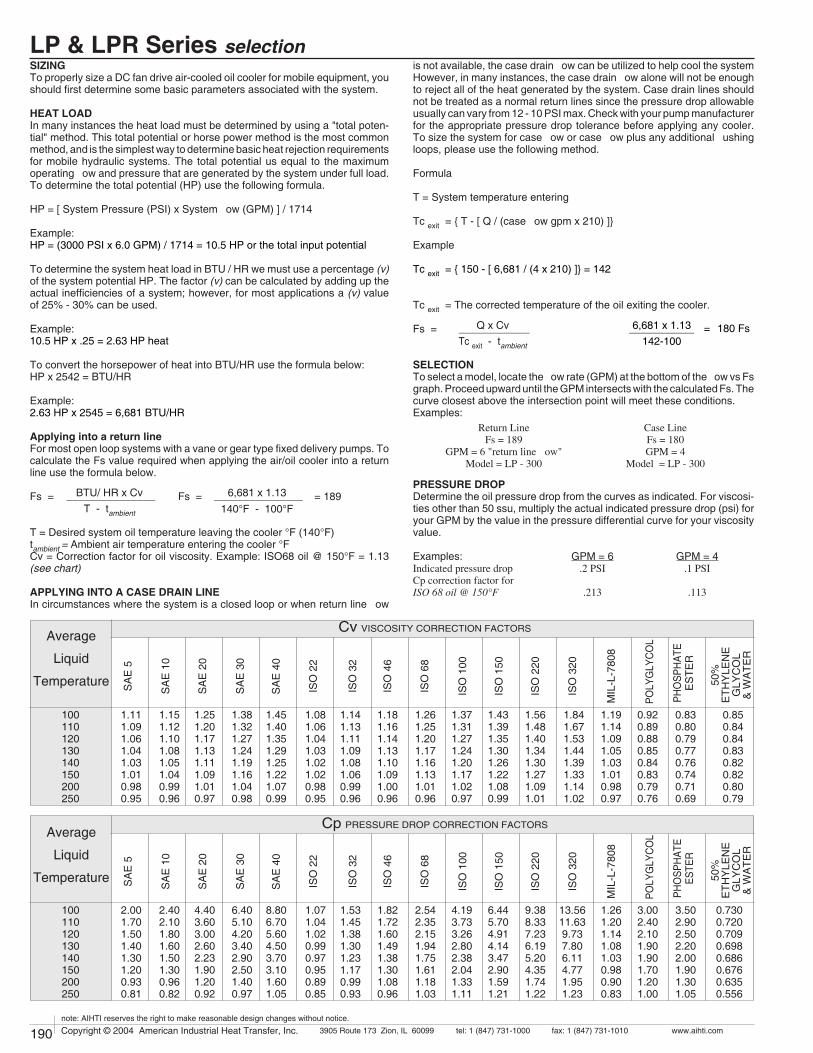
190 Copyright © 2004 American Industrial Heat Transfer, Inc. tel: 1 (847) 731-10003905 Route 173 Zion, IL 60099 www.aihti.comfax: 1 (847) 731-1010
note: AIHTI reserves the right to make reasonable design changes without notice.
191Copyright © 2004 American Industrial Heat Transfer, Inc. tel: 1 (847) 731-10003905 Route 173 Zion, IL 60099 www.aihti.comfax: 1 (847) 731-1010
note: AIHTI reserves the right to make reasonable design changes without notice.
Cv VISCOSITY CORRECTION FACTORS
ISO
22
SA
E 3
0
SA
E 1
0
SA
E 5
1.381.321.271.241.191.161.040.98
1.251.201.171.131.111.091.010.97
1.151.121.101.081.051.040.990.96
1.451.401.351.291.251.221.070.99
1.111.091.061.041.031.010.980.95
50%
ETH
YLE
NE
GLY
CO
L&
WA
TER
POLY
GLY
CO
L
0.920.890.880.850.840.830.790.76
PHO
SPH
ATE
ES
TER
0.830.800.790.770.760.740.710.69
0.850.840.840.830.820.820.800.79
Average
Liquid
Temperature
100110120130140150200250
ISO
32
1.081.061.041.031.021.020.980.95
ISO
46
1.141.131.111.091.081.060.990.96
ISO
68
1.181.161.141.131.101.091.000.96
ISO
100
1.261.251.201.171.161.131.010.96
ISO
150
1.371.311.271.241.201.171.020.97
ISO
220
1.431.391.351.301.261.221.080.99
ISO
320
1.561.481.401.341.301.271.091.01
SA
E 4
0
MIL
-L-7
808
1.191.141.091.051.031.010.980.97
SA
E 2
0
1.841.671.531.441.391.331.141.02
Cp PRESSURE DROP CORRECTION FACTORS
ISO
22
SA
E 3
0
SA
E 1
0
SA
E 5
6.405.104.203.402.902.501.400.97
4.403.603.002.602.231.901.200.92
2.402.101.801.601.501.300.960.82
8.806.705.604.503.703.101.601.05
2.001.701.501.401.301.200.930.81
50%
ETH
YLE
NE
GLY
CO
L&
WA
TER
POLY
GLY
CO
L
3.002.402.101.901.901.701.201.00
PHO
SPH
ATE
ESTE
R
3.502.902.502.202.001.901.301.05
0.7300.7200.7090.6980.6860.6760.6350.556
Average
Liquid
Temperature
100110120130140150200250
ISO
32
1.071.041.020.990.970.950.890.85
ISO
46
1.531.451.381.301.231.170.990.93
ISO
68
1.821.721.601.491.381.301.080.96
ISO
100
2.542.352.151.941.751.611.181.03
ISO
150
4.193.733.262.802.382.041.331.11
ISO
220
6.445.704.914.143.472.901.591.21
ISO
320
9.388.337.236.195.204.351.741.22
SA
E 4
0
MIL
-L-7
808
1.261.201.141.081.030.980.900.83
SA
E 2
0
13.5611.63 9.73 7.80 6.11 4.77 1.95 1.23
LP & LPR Series selection
SIZINGTo properly size a DC fan drive air-cooled oil cooler for mobile equipment, you should first determine some basic parameters associated with the system.
HEAT LOADIn many instances the heat load must be determined by using a "total poten-tial" method. This total potential or horse power method is the most common method, and is the simplest way to determine basic heat rejection requirements for mobile hydraulic systems. The total potential us equal to the maximum operating flow and pressure that are generated by the system under full load. To determine the total potential (HP) use the following formula.
HP = [ System Pressure (PSI) x System flow (GPM) ] / 1714
Example:HP = (3000 PSI x 6.0 GPM) / 1714 = 10.5 HP or the total input potential
To determine the system heat load in BTU / HR we must use a percentage (v) of the system potential HP. The factor (v) can be calculated by adding up the actual inefficiencies of a system; however, for most applications a (v) value of 25% - 30% can be used.
Example:10.5 HP x .25 = 2.63 HP heat
To convert the horsepower of heat into BTU/HR use the formula below:HP x 2542 = BTU/HR
Example:2.63 HP x 2545 = 6,681 BTU/HR
Applying into a return lineFor most open loop systems with a vane or gear type fixed delivery pumps. To calculate the Fs value required when applying the air/oil cooler into a return line use the formula below.
Fs = Fs = = 189
T = Desired system oil temperature leaving the cooler °F (140°F)tambient = Ambient air temperature entering the cooler °FCv = Correction factor for oil viscosity. Example: ISO68 oil @ 150°F = 1.13 (see chart)
APPLYING INTO A CASE DRAIN LINEIn circumstances where the system is a closed loop or when return line flow
is not available, the case drain flow can be utilized to help cool the system However, in many instances, the case drain flow alone will not be enough to reject all of the heat generated by the system. Case drain lines should not be treated as a normal return lines since the pressure drop allowable usually can vary from 12 - 10 PSI max. Check with your pump manufacturer for the appropriate pressure drop tolerance before applying any cooler. To size the system for case flow or case flow plus any additional flushing loops, please use the following method.
Formula
T = System temperature entering
Tc exit = { T - [ Q / (case flow gpm x 210) ]} Example
Tc exit = { 150 - [ 6,681 / (4 x 210) ]} = 142
Tc exit = The corrected temperature of the oil exiting the cooler.
Fs =
SELECTIONTo select a model, locate the flow rate (GPM) at the bottom of the flow vs Fs graph. Proceed upward until the GPM intersects with the calculated Fs. The curve closest above the intersection point will meet these conditions. Examples:
PRESSURE DROPDetermine the oil pressure drop from the curves as indicated. For viscosi-ties other than 50 ssu, multiply the actual indicated pressure drop (psi) for your GPM by the value in the pressure differential curve for your viscosity value.
Examples: GPM = 6 GPM = 4Indicated pressure drop .2 PSI .1 PSICp correction factor forISO 68 oil @ 150°F .213 .113
BTU/ HR x Cv _______________T - tambient
Q x Cv ____________Tc exit - tambient
6,681 x 1.13 ___________ = 180 Fs 142-100
Return LineFs = 189
GPM = 6 "return line flow"Model = LP - 300
Case LineFs = 180GPM = 4
Model = LP - 300
6,681 x 1.13 _______________140°F - 100°F

190 Copyright © 2004 American Industrial Heat Transfer, Inc. tel: 1 (847) 731-10003905 Route 173 Zion, IL 60099 www.aihti.comfax: 1 (847) 731-1010
note: AIHTI reserves the right to make reasonable design changes without notice.
191Copyright © 2004 American Industrial Heat Transfer, Inc. tel: 1 (847) 731-10003905 Route 173 Zion, IL 60099 www.aihti.comfax: 1 (847) 731-1010
note: AIHTI reserves the right to make reasonable design changes without notice.
600
300
150
1000
800
600500
400
300
200
80
6021 3 4 5 6 7 8 9 10 20 30 40 50 60 80 100 200 300
100
GPM
Fs
BA
C D E F G H
BA
C D E F G
BA
C D E F G H I J
LP MOTOR DATA
12 / 24
12 / 24
12 / 24
12 / 24
12 / 24
12 / 24
LP - 150
LPR - 150
LP - 300
LPR - 300
LP - 600
LPR - 600
950
950
950
950
1900
1900
9.0 / 4.5
9.0 / 4.5
9.0 / 4.5
9.0 / 4.5
9.0 / 4.5
9.0 / 4.5
2000
2000
2000
2000
2000
2000
RPMFLA Per Motor Volts Total CFMModel
STANDARD CONSTRUCTION MATERIALS
PIPING HOOK-UP
OUT
IN
IN or OUT IN or OUTLP LP
LPR
Inlet Only
Tubes Copper
Fins Aluminum
Turbulators Steel
Manifold Steel
Mount. bracket Steel
Cabinet Steel
Fan Blade Aluminum
Standard Construction Materials
Operating Pressure 300 psig
Operating Temp. 400 oF
Standard Unit Ratings
LP & LPR Series motor data
]Represents desired fluid leaving the cooler.
Horsepower to be removed (HP) x 2545 x Cv °F (Oil Leaving] - Ambient Air Entering) Fs =
OIL PRESSURE DROP (PSI) CODE
BTUhr °F
=
PERFORMANCE CALCULATIOND = 4 PSIE = 5 PSIF = 10 PSI
G = 15 PSIH = 20 PSI I = 25 PSI
J = 30 PSIA = 1 PSIB = 2 PSIC = 3 PSI
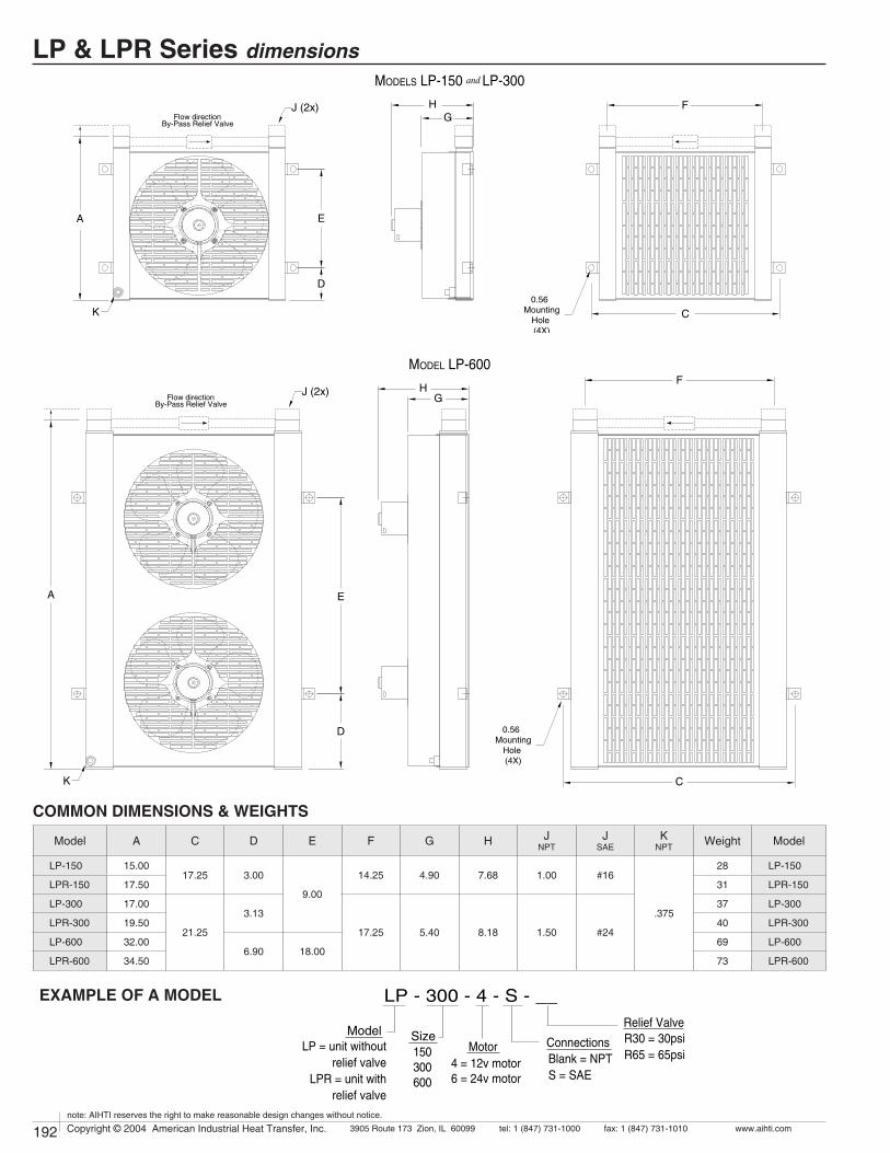
192 Copyright © 2004 American Industrial Heat Transfer, Inc. tel: 1 (847) 731-10003905 Route 173 Zion, IL 60099 www.aihti.comfax: 1 (847) 731-1010
note: AIHTI reserves the right to make reasonable design changes without notice.
193Copyright © 2004 American Industrial Heat Transfer, Inc. tel: 1 (847) 731-10003905 Route 173 Zion, IL 60099 www.aihti.comfax: 1 (847) 731-1010
note: AIHTI reserves the right to make reasonable design changes without notice.
EXAMPLE OF A MODEL LP - 300 - 4 - S - __
Model Size ConnectionsMotorBlank = NPTS = SAE
LP = unit withoutrelief valve
LPR = unit withrelief valve
4 = 12v motor6 = 24v motor
Relief ValveR30 = 30psiR65 = 65psi150
300600
LP & LPR Series dimensions
Model A C D E F G H JNPT
JSAE
KNPT Weight Model
LP-150 15.0017.25 3.00
9.00
14.25 4.90 7.68 1.00 #16
.375
28 LP-150
LPR-150 17.50 31 LPR-150
LP-300 17.00
21.25
3.13
17.25 5.40 8.18 1.50 #24
37 LP-300
LPR-300 19.50 40 LPR-300
LP-600 32.006.90 18.00
69 LP-600
LPR-600 34.50 73 LPR-600
COMMON DIMENSIONS & WEIGHTS
By-Pass Relief ValveFlow direction
D
E
HG
C0.56
MountingHole (4X)
F
A
K
J (2x)
D
E
H
C
0.56 Mounting
Hole (4X)
F
A
K
By-Pass Relief ValveFlow direction G
J (2x)
MODEL LP-600
MODELS LP-150 and LP-300

192 Copyright © 2004 American Industrial Heat Transfer, Inc. tel: 1 (847) 731-10003905 Route 173 Zion, IL 60099 www.aihti.comfax: 1 (847) 731-1010
note: AIHTI reserves the right to make reasonable design changes without notice.
193Copyright © 2004 American Industrial Heat Transfer, Inc. tel: 1 (847) 731-10003905 Route 173 Zion, IL 60099 www.aihti.comfax: 1 (847) 731-1010
note: AIHTI reserves the right to make reasonable design changes without notice.
LP & LPR Series installation & maintenanceReceiving / Installationa) Inspect unit for any shipping damage before uncrating. Indicate all damages to the trucking firms' delivery person and mark it on the receiving bill before accepting the freight. Make sure that the core and fan are not damaged. Rotate the fan blade to make sure that it moves freely. Since the warranty is based upon the unit date code located on the model identification tag, removal or manipulation of the identification tag will void the manufacturers warranty.
c) Standard Enamel Coating: American Industrial provides its standard products with a normal base coat of oil base air cure enamel paint. The enamel paint is applied as a temporary protective and esthetic coating prior to shipment. While the standard enamel coating is durable, American Industrial does not warranty it as a long-term finish coating. It is strongly suggested that a more durable final coating be applied after installation or prior to long-term storage in a corrosive environment to cover any accidental scratches, enhance esthetics, and further prevent corrosion. It is the responsibility of the customer to provide regular maintenance against chips, scratches, etc... and regular touch up maintenance must be provided for long-term benefits and corrosion prevention.
d) Special Coatings: American Industrial offers as customer options, Air-Dry Epoxy, and Heresite (Air-Dry Phenolic) coatings at additional cost. American Industrial offers special coatings upon request, however American Industrial does not warrantee coatings to be a permanent solution for any equipment against corrosion. It is the responsibility of the customer to provide regular maintenance against chips, scratches, etc... and regular touch up maintenance must be provided for long-term benefits and corrosion prevention.
e) American Industrial recommends that the equipment supplied should be installed by qualified personnel who have solid understanding of system design, pressure and temperature ratings, and piping assembly. Verify the service conditions of the system prior to applying any air cooled heat exchanger series cooler. If the system pressure or temperature does not fall within the parameters on model rating tag located on the heat exchanger, contact our factory prior to installation or operation.
g) Heat exchanger should be securely fastened using the mounting foot brackets (included). All mounting holes should be used to secure unit into place.
h) Connections should be made in configurations exactly as indicated in the "piping hook up" illustration. The process flow entering the "Fluid IN" port and exiting the "Fluid OUT" port eliminates air pockets and assures that the unit will stay completely flooded. Flexible hose can be applied to reduce the risk of core failure due to thermal expansion or system vibra-tion. Piping alignment and support is required for hoses longer than four feet in length and for piping exerting more than 10 lbs of dynamic force. It is recommended that filtration be located ahead of the heat exchanger to prevent excessive backpressure and clogging.
i) With respect to the heat exchangers nozzle size, flow line sizes should be sized to handle the appropriate flow rate and system pressure drop requirements, normally flow line rates of about 8-12 feet per second and inlet pressure less than 100psig are experienced. If the flow line size is larger than the heat exchanger nozzle size, additional pressure loss beyond the published pressure loss data may occur.
j) Electric motors should be connected only to supply source of the same characteristics as indicated on the electric motor information plate. Prior to starting, verify that the motor and fan spin freely without obstruction. Check carefully that the fan turns in the correct rotation direction (normally counter clockwise) from the motor side (fan direction arrow). Failure to operate the fan in the proper direction could reduce performance or cause serious damage to the heat exchanger or other components.
k) Solely at the request of customers, American Industrial provides direct acting internal inlet port to outlet port bypass relief valves as an addi-tional safe guard against excessive flow and over pressurization of the heat exchanger. American Industrial purchases and applies high quality hydraulic system cartridge valves and components made available for hydraulic system use. However, American Industrial does not specify, recommend, suggest, guarantee, or warrantee the internal relief valve or its performance to safe guard the heat exchanger from damage or prevent failure due to excessive flow or over pressurization. It is the ultimately the sole responsibility of the customer/user to verify with the original equipment manufacture all conditions associated with applying an additional system relief valve prior to application.
MaintenanceRegular maintenance intervals based upon the surrounding and opera-tional conditions should be maintained to verify equipment performance and to prevent premature component failure. Since some of the compo-nents such as, motors, fans, etc... are not manufactured by American Industrial, maintenance requirements provided by the manufacture must be followed.
a) Inspect the entire heat exchanger and motor/fan assembly for loosened bolts, loose connections, broken components, rust spots, corrosion, fin/coil clogging, or external leakage. Make immediate repairs to all affected areas prior to restarting and operating the heat exchanger or its components.
b) Heat exchangers operating in oily or dusty environments will often need to have the coil cooling fins cleaned. Oily or clogged fins should be cleaned by carefully brushing the fins and tubes with water or a non-ag-gressive degreasing agent mixture (Note: Cleaning agents that are not compatible with copper, brass, aluminum, steel or stainless steel should not be used). A compressed air or a water stream can be used to dislodge dirt and clean the coil further. Any external dirt or oil on the electric motor and fan assembly should be removed. Caution: Be sure to disconnect the electric motor from its power source prior to doing any maintenance.
c) In most cases it is not necessary to internally flush the coil. In circum-stances where the coil has become plugged or has a substantial buildup of material, flushing the coil with water or a solvent may be done. Flush-ing solvents should be non-aggressive suitable for the materials of con-struction. Serviceable Core® models can be disassembled and inspected or cleaned if required.
e) Fan blades should be cleaned and inspected for tightness during the regular maintenance schedule when handling a fan blade care must be given to avoid bending or striking any of the blades. Fan blades are fac-tory balanced and will not operate properly if damaged or unbalanced. Damaged fan blades can cause excessive vibration and severe damage to the heat exchanger or drive motor. Replace any damaged fan with an American industrial suggested replacement.
f) Air cooled exchanger cabinets are constructed using 7ga. through 18ga. steel that may be bent back into position if damaged. Parts that are not repairable can be purchased through American Industrial.
g) Coil fins that become flattened can be combed back into position. This process may require removal of the coil from the cabinet.
h) It is not advisable to attempt repairs to brazed joints of a brazed construction coil unless it will be done by an expert in silver solder braz-ing. Brazed coils are heated uniformly during the original manufacturing process to prevent weak zones from occurring. Uncontrolled reheating of the coil may result in weakening of the tube joints surrounding the repair area. In many instances brazed units that are repaired will not hold up as well to the rigors of the system as will a new coil. American Industrial will not warranty or be responsible for any repairs done by unauthorized sources. Manipulation in any way other than normal application will void the manufactures warranty.

182 Copyright © 2004 American Industrial Heat Transfer, Inc. tel: 1 (847) 731-10003905 Route 173 Zion, IL 60099 www.aihti.comfax: 1 (847) 731-1010
note: AIHTI reserves the right to make reasonable design changes without notice.
183Copyright © 2004 American Industrial Heat Transfer, Inc. tel: 1 (847) 731-10003905 Route 173 Zion, IL 60099 www.aihti.comfax: 1 (847) 731-1010
note: AIHTI reserves the right to make reasonable design changes without notice.
• Reliable, tested, rugged.
• Computerized selection available.
• Custom designs to fit your needs.
• Operating temperature of 400° F and pressure
of 300PSI.
MOBILE AIR COOLED
OIL COOLERS
AOMF SERIES
• Standard NPT or SAE connections.
• Cools: Fluid power systems, lubrication
systems, hydraulic presses,gear drives,
torque convertors, machine tools, etc...
AOMF-2
®
12 volt & 24 volt DC motor
AOMF-1
AOMF-4

184 Copyright © 2004 American Industrial Heat Transfer, Inc. tel: 1 (847) 731-10003905 Route 173 Zion, IL 60099 www.aihti.comfax: 1 (847) 731-1010
note: AIHTI reserves the right to make reasonable design changes without notice.
185Copyright © 2004 American Industrial Heat Transfer, Inc. tel: 1 (847) 731-10003905 Route 173 Zion, IL 60099 www.aihti.comfax: 1 (847) 731-1010
note: AIHTI reserves the right to make reasonable design changes without notice.
SIZINGTo properly size a DC fan drive air-cooled oil cooler for mobile equipment, you should first determine some basic parameters associated with the system.
HEAT LOADIn many instances the heat load must be determined by using a "total poten-tial" method. This total potential or horse power method is the most common method, and is the simplest way to determine basic heat rejection requirements for mobile hydraulic systems. The total potential us equal to the maximum operating flow and pressure that are generated by the system under full load. To determine the total potential (HP) use the following formula.
HP = [ System Pressure (PSI) x System flow (GPM) ] / 1714
Example:HP = (3000 PSI x 40 GPM) / 1714 = 70 HP or the total input potential
To determine the system heat load in BTU / HR we must use a percentage (v) of the system potential HP. The factor (v) can be calculated by adding up the actual inefficiencies of a system; however, for most applications a (v) value of 25% - 30% can be used.
Example:20 HP x .25 = 5 HP heat
To convert the horsepower of heat into BTU/HR use the formula below:HP x 2542 = BTU/HR
Example:5 HP x 2545 = 12,725 BTU/HR
Applying into a return lineFor most open loop systems with a vane or gear type fixed delivery pumps. To calculate the Fs value required when applying the air/oil cooler into a return line use the formula below.
Fs =
T = Desired system oil temperature leaving the cooler °Ftambient = Ambient air temperature entering the cooler °FCv = Correction factor for oil viscosity. Example: ISO68 oil @ 150°F = 1.13 (see chart)
APPLYING INTO A CASE DRAIN LINEIn circumstances where the system is a closed loop or when return line flow
is not available, the case drain flow can be utilized to help cool the system However, in many instances, the case drain flow alone will not be enough to reject all of the heat generated by the system. Case drain lines should not be treated as a normal return lines since the pressure drop allowable usually can vary from 12 - 10 PSI max. Check with your pump manufacturer for the appropriate pressure drop tolerance before applying any cooler. To size the system for case flow or case flow plus any additional flushing loops, please use the following method.
Formula
T = System temperature entering
Tc exit = { T - [ Q / (case flow gpm x 210) ]} Example
Tc exit = { 150 - [ 12,725 / (8 x 210) ]} = 142.4
Tc exit = The corrected temperature of the oil exiting the cooler.
Fs =
SELECTIONTo select a model, locate the flow rate (GPM) at the bottom of the flow vs Fs graph. Proceed upward until the GPM intersects with the calculated Fs. The curve closest above the intersection point will meet these conditions. Examples:
PRESSURE DROPDetermine the oil pressure drop from the curves as indicated. For viscosi-ties other than 50 ssu, multiply the actual indicated pressure drop (psi) for your GPM by the value in the pressure differential curve for your viscosity value.
Examples: GPM = 10 GPM = 8Indicated pressure drop 2.9PSI 1.9 PSICp correction factor forISO 68 oil @ 150°F 3.72 2.47
BTU/ HR x Cv _______________T - tambient
Q x Cv ____________Tc exit - tambient
12,725 x 1.13 ___________ = 300 Fs 142.4-100
Return LineFs = 318
GPM = 10 "return line flow"Model = AOMF - 2
Case LineFs = 300GPM = 8
Model = AOMF - 2
Cv VISCOSITY CORRECTION FACTORS
ISO
22
SA
E 3
0
SA
E 1
0
SA
E 5
1.381.321.271.241.191.161.040.98
1.251.201.171.131.111.091.010.97
1.151.121.101.081.051.040.990.96
1.451.401.351.291.251.221.070.99
1.111.091.061.041.031.010.980.95
50%
ETH
YLE
NE
GLY
CO
L&
WA
TER
POLY
GLY
CO
L
0.920.890.880.850.840.830.790.76
PHO
SPH
ATE
ES
TER
0.830.800.790.770.760.740.710.69
0.850.840.840.830.820.820.800.79
Average
Liquid
Temperature
100110120130140150200250
ISO
32
1.081.061.041.031.021.020.980.95
ISO
46
1.141.131.111.091.081.060.990.96
ISO
68
1.181.161.141.131.101.091.000.96
ISO
100
1.261.251.201.171.161.131.010.96
ISO
150
1.371.311.271.241.201.171.020.97
ISO
220
1.431.391.351.301.261.221.080.99
ISO
320
1.561.481.401.341.301.271.091.01
SA
E 4
0
MIL
-L-7
808
1.191.141.091.051.031.010.980.97
SA
E 2
0
1.841.671.531.441.391.331.141.02
Cp PRESSURE DROP CORRECTION FACTORS
ISO
22
SA
E 3
0
SA
E 1
0
SA
E 5
6.405.104.203.402.902.501.400.97
4.403.603.002.602.231.901.200.92
2.402.101.801.601.501.300.960.82
8.806.705.604.503.703.101.601.05
2.001.701.501.401.301.200.930.81
50%
ETH
YLE
NE
GLY
CO
L&
WA
TER
POLY
GLY
CO
L
3.002.402.101.901.901.701.201.00
PHO
SPH
ATE
ESTE
R
3.502.902.502.202.001.901.301.05
0.7300.7200.7090.6980.6860.6760.6350.556
Average
Liquid
Temperature
100110120130140150200250
ISO
32
1.071.041.020.990.970.950.890.85
ISO
46
1.531.451.381.301.231.170.990.93
ISO
68
1.821.721.601.491.381.301.080.96
ISO
100
2.542.352.151.941.751.611.181.03
ISO
150
4.193.733.262.802.382.041.331.11
ISO
220
6.445.704.914.143.472.901.591.21
ISO
320
9.388.337.236.195.204.351.741.22
SA
E 4
0
MIL
-L-7
808
1.261.201.141.081.030.980.900.83
SA
E 2
0
13.5611.63 9.73 7.80 6.11 4.77 1.95 1.23
AOMF Series selection
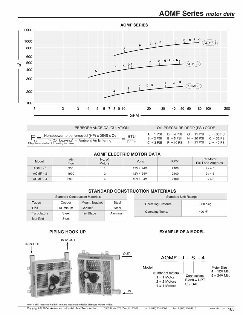
184 Copyright © 2004 American Industrial Heat Transfer, Inc. tel: 1 (847) 731-10003905 Route 173 Zion, IL 60099 www.aihti.comfax: 1 (847) 731-1010
note: AIHTI reserves the right to make reasonable design changes without notice.
185Copyright © 2004 American Industrial Heat Transfer, Inc. tel: 1 (847) 731-10003905 Route 173 Zion, IL 60099 www.aihti.comfax: 1 (847) 731-1010
note: AIHTI reserves the right to make reasonable design changes without notice.
EXAMPLE OF A MODEL
AOMF-4
AOMF-2
AOMF-1
2000
1000
800
600
500
400
300
200
21 3 4 5 6 7 8 9 10 20 30 40 50 60 80 100 200
100
AOMF SERIES
GPM
Fs
BA
C D E F G H I J
BA
C D E F G
BA
C D EF G H
H
I J K L
Horsepower to be removed (HP) x 2545 x Cv °F (Oil Leaving] - Ambient Air Entering) Fs =
OIL PRESSURE DROP (PSI) CODE
BTUhr °F
=
PERFORMANCE CALCULATION
]Represents desired fluid leaving the cooler.
D = 4 PSIE = 5 PSIF = 10 PSI
G = 15 PSIH = 20 PSI I = 25 PSI
J = 30 PSIK = 35 PSIL = 40 PSI
A = 1 PSIB = 2 PSIC = 3 PSI
PIPING HOOK UP
AOMF ELECTRIC MOTOR DATARPMNo. of
MotorsAir
Flow VoltsPer Motor
Full Load AmperesModel
12V / 24V
12V / 24V
12V / 24V
AOMF - 1
AOMF - 2
AOMF - 4
9 / 4.5
9 / 4.5
9 / 4.5
950
1900
3900
1
2
4
2100
2100
2100
Tubes Copper
Fins Aluminum
Turbulators Steel
Manifold Steel
Mount. bracket Steel
Cabinet Steel
Fan Blade Aluminum
Standard Construction Materials
STANDARD CONSTRUCTION MATERIALS
Operating Pressure 300 psig
Operating Temp. 400 oF
Standard Unit Ratings
AOMF - 1 - S - 4
Model
Number of motorsConnectionsBlank = NPTS = SAE
Motor Size4 = 12V Mtr.6 = 24V Mtr.1 = 1 Motor
2 = 2 Motors4 = 4 Motors
OUT
IN
IN or OUTIN or OUT
OUT
IN
IN or OUTIN or OUT
AOMF Series motor data
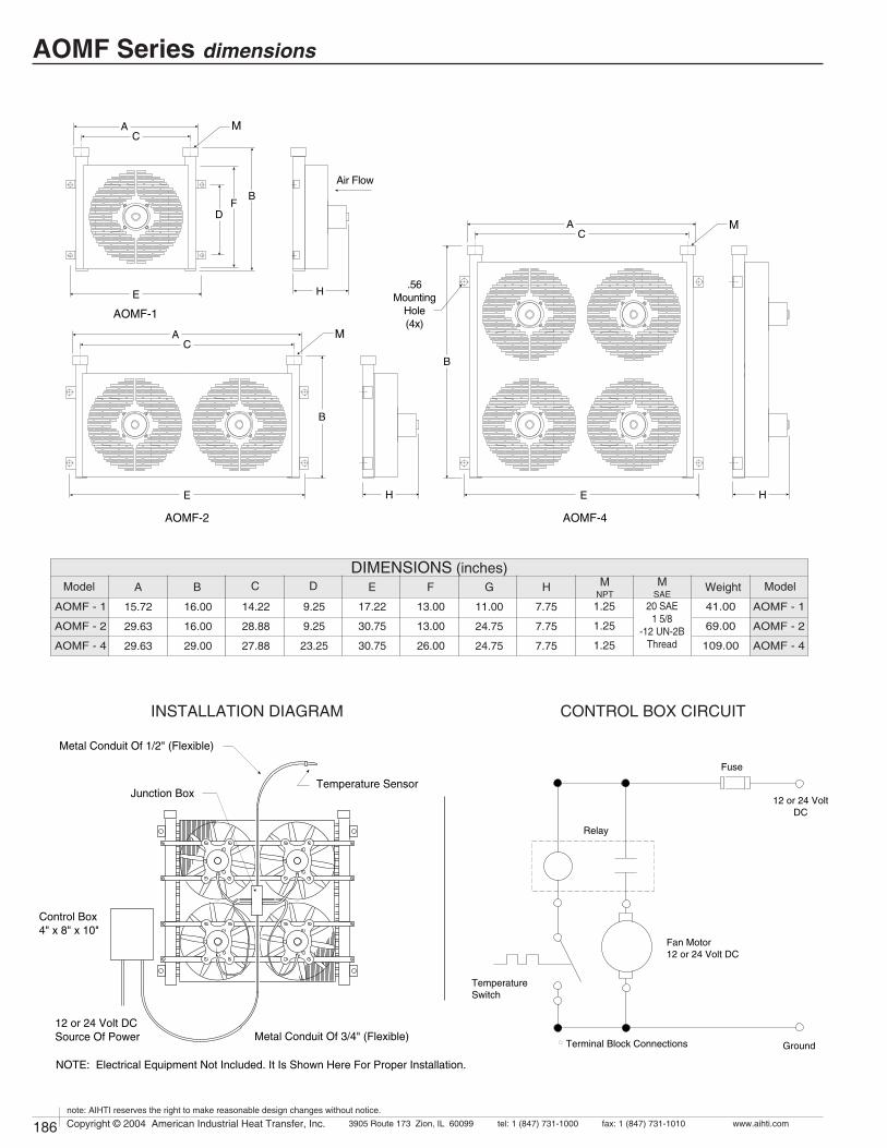
186 Copyright © 2004 American Industrial Heat Transfer, Inc. tel: 1 (847) 731-10003905 Route 173 Zion, IL 60099 www.aihti.comfax: 1 (847) 731-1010
note: AIHTI reserves the right to make reasonable design changes without notice.
187Copyright © 2004 American Industrial Heat Transfer, Inc. tel: 1 (847) 731-10003905 Route 173 Zion, IL 60099 www.aihti.comfax: 1 (847) 731-1010
note: AIHTI reserves the right to make reasonable design changes without notice.
Metal Conduit Of 1/2" (Flexible)
Temperature Sensor
Control Box4" x 8" x 10"
12 or 24 Volt DCSource Of Power Metal Conduit Of 3/4" (Flexible)
NOTE: Electrical Equipment Not Included. It Is Shown Here For Proper Installation.
Junction Box
Relay
Fuse
Fan Motor12 or 24 Volt DC
TemperatureSwitch
Terminal Block Connections Ground
12 or 24 VoltDC
AOMF-1
AC
BF
D
E
E
M
H
H E H
AOMF-2 AOMF-4
AC
AC
M
M
B
B
Air Flow
.56Mounting
Hole(4x)
Model MNPT
WeightGFDCBA
DIMENSIONS (inches)M
SAE14.22
28.88
27.88
11.00
24.75
24.75
16.00
16.00
29.00
15.72
29.63
29.63
9.25
9.25
23.25
17.22
30.75
30.75
13.00
13.00
26.00
1.25
1.25
1.25
AOMF - 1
AOMF - 2
AOMF - 4
20 SAE1 5/8
-12 UN-2B Thread
E Model
AOMF - 1
AOMF - 2
AOMF - 4
H
7.75
7.75
7.75
INSTALLATION DIAGRAM CONTROL BOX CIRCUIT
41.00
69.00
109.00
AOMF Series dimensions

186 Copyright © 2004 American Industrial Heat Transfer, Inc. tel: 1 (847) 731-10003905 Route 173 Zion, IL 60099 www.aihti.comfax: 1 (847) 731-1010
note: AIHTI reserves the right to make reasonable design changes without notice.
187Copyright © 2004 American Industrial Heat Transfer, Inc. tel: 1 (847) 731-10003905 Route 173 Zion, IL 60099 www.aihti.comfax: 1 (847) 731-1010
note: AIHTI reserves the right to make reasonable design changes without notice.
AOMF Series installation & maintenanceReceiving / Installationa) Inspect unit for any shipping damage before uncrating. Indicate all damages to the trucking firms' delivery person and mark it on the receiving bill before accepting the freight. Make sure that the core and fan are not damaged. Rotate the fan blade to make sure that it moves freely. Since the warranty is based upon the unit date code located on the model identification tag, removal or manipulation of the identification tag will void the manufacturers warranty.
c) Standard Enamel Coating: American Industrial provides its standard products with a normal base coat of oil base air cure enamel paint. The enamel paint is applied as a temporary protective and esthetic coating prior to shipment. While the standard enamel coating is durable, American Industrial does not warranty it as a long-term finish coating. It is strongly suggested that a more durable final coating be applied after installation or prior to long-term storage in a corrosive environment to cover any accidental scratches, enhance esthetics, and further prevent corrosion. It is the responsibility of the customer to provide regular maintenance against chips, scratches, etc... and regular touch up maintenance must be provided for long-term benefits and corrosion prevention.
d) Special Coatings: American Industrial offers as customer options, Air-Dry Epoxy, and Heresite (Air-Dry Phenolic) coatings at additional cost. American Industrial offers special coatings upon request, however American Industrial does not warrantee coatings to be a permanent solution for any equipment against corrosion. It is the responsibility of the customer to provide regular maintenance against chips, scratches, etc... and regular touch up maintenance must be provided for long-term benefits and corrosion prevention.
e) American Industrial recommends that the equipment supplied should be installed by qualified personnel who have solid understanding of system design, pressure and temperature ratings, and piping assembly. Verify the service conditions of the system prior to applying any air cooled heat exchanger series cooler. If the system pressure or temperature does not fall within the parameters on model rating tag located on the heat exchanger, contact our factory prior to installation or operation.
g) Heat exchanger should be securely fastened using the mounting foot brackets (included). All mounting holes should be used to secure unit into place.
h) Connections should be made in configurations exactly as indicated in the "piping hook up" illustration. The process flow entering the "Fluid IN" port and exiting the "Fluid OUT" port eliminates air pockets and assures that the unit will stay completely flooded. Flexible hose can be applied to reduce the risk of core failure due to thermal expansion or system vibra-tion. Piping alignment and support is required for hoses longer than four feet in length and for piping exerting more than 10 lbs of dynamic force. It is recommended that filtration be located ahead of the heat exchanger to prevent excessive backpressure and clogging.
i) With respect to the heat exchangers nozzle size, flow line sizes should be sized to handle the appropriate flow rate and system pressure drop requirements, normally flow line rates of about 8-12 feet per second and inlet pressure less than 100psig are experienced. If the flow line size is larger than the heat exchanger nozzle size, additional pressure loss beyond the published pressure loss data may occur.
j) Electric motors should be connected only to supply source of the same characteristics as indicated on the electric motor information plate. Prior to starting, verify that the motor and fan spin freely without obstruction. Check carefully that the fan turns in the correct rotation direction (normally counter clockwise) from the motor side (fan direction arrow). Failure to operate the fan in the proper direction could reduce performance or cause serious damage to the heat exchanger or other components.
k) Solely at the request of customers, American Industrial provides direct acting internal inlet port to outlet port bypass relief valves as an addi-tional safe guard against excessive flow and over pressurization of the heat exchanger. American Industrial purchases and applies high quality hydraulic system cartridge valves and components made available for hydraulic system use. However, American Industrial does not specify, recommend, suggest, guarantee, or warrantee the internal relief valve or its performance to safe guard the heat exchanger from damage or prevent failure due to excessive flow or over pressurization. It is the ultimately the sole responsibility of the customer/user to verify with the original equipment manufacture all conditions associated with applying an additional system relief valve prior to application.
MaintenanceRegular maintenance intervals based upon the surrounding and opera-tional conditions should be maintained to verify equipment performance and to prevent premature component failure. Since some of the compo-nents such as, motors, fans, etc... are not manufactured by American Industrial, maintenance requirements provided by the manufacture must be followed.
a) Inspect the entire heat exchanger and motor/fan assembly for loosened bolts, loose connections, broken components, rust spots, corrosion, fin/coil clogging, or external leakage. Make immediate repairs to all affected areas prior to restarting and operating the heat exchanger or its components.
b) Heat exchangers operating in oily or dusty environments will often need to have the coil cooling fins cleaned. Oily or clogged fins should be cleaned by carefully brushing the fins and tubes with water or a non-ag-gressive degreasing agent mixture (Note: Cleaning agents that are not compatible with copper, brass, aluminum, steel or stainless steel should not be used). A compressed air or a water stream can be used to dislodge dirt and clean the coil further. Any external dirt or oil on the electric motor and fan assembly should be removed. Caution: Be sure to disconnect the electric motor from its power source prior to doing any maintenance.
c) In most cases it is not necessary to internally flush the coil. In circum-stances where the coil has become plugged or has a substantial buildup of material, flushing the coil with water or a solvent may be done. Flush-ing solvents should be non-aggressive suitable for the materials of con-struction. Serviceable Core® models can be disassembled and inspected or cleaned if required.
e) Fan blades should be cleaned and inspected for tightness during the regular maintenance schedule when handling a fan blade care must be given to avoid bending or striking any of the blades. Fan blades are fac-tory balanced and will not operate properly if damaged or unbalanced. Damaged fan blades can cause excessive vibration and severe damage to the heat exchanger or drive motor. Replace any damaged fan with an American industrial suggested replacement.
f) Air cooled exchanger cabinets are constructed using 7ga. through 18ga. steel that may be bent back into position if damaged. Parts that are not repairable can be purchased through American Industrial.
g) Coil fins that become flattened can be combed back into position. This process may require removal of the coil from the cabinet.
h) It is not advisable to attempt repairs to brazed joints of a brazed construction coil unless it will be done by an expert in silver solder braz-ing. Brazed coils are heated uniformly during the original manufacturing process to prevent weak zones from occurring. Uncontrolled reheating of the coil may result in weakening of the tube joints surrounding the repair area. In many instances brazed units that are repaired will not hold up as well to the rigors of the system as will a new coil. American Industrial will not warranty or be responsible for any repairs done by unauthorized sources. Manipulation in any way other than normal application will void the manufactures warranty.

202 Copyright © 2004 American Industrial Heat Transfer, Inc. tel: 1 (847) 731-10003905 Route 173 Zion, IL 60099 www.aihti.comfax: 1 (847) 731-1010
note: AIHTI reserves the right to make reasonable design changes without notice.
203Copyright © 2004 American Industrial Heat Transfer, Inc. tel: 1 (847) 731-10003905 Route 173 Zion, IL 60099 www.aihti.comfax: 1 (847) 731-1010
note: AIHTI reserves the right to make reasonable design changes without notice.
• Mounts directly to TEFC electric motor.
• Fits NEMA frame sizes 48 through 365.
• Standard NPT or SAE connections.
• Operating temperature of 400°F
& pressure of 300PSI.
• Cools case drains, hydraulic presses, bearings
gear boxes, hydraulic tools, etc…
AIR COOLED
OIL COOLERS
BM SERIES
BM - 201 thru BM - 322 SERIES
BM - 101 & BM - 102 SERIES
®
MODELS TO ACCOMMODATEELECTRIC MOTOR NEMA FRAME SIZES
48 - 184 213 - 256 254 - 286 324 - 365BM - 101 BM - 201 BM - 301 BM - 321BM - 102 BM - 202 BM - 302 BM - 322

204 Copyright © 2004 American Industrial Heat Transfer, Inc. tel: 1 (847) 731-10003905 Route 173 Zion, IL 60099 www.aihti.comfax: 1 (847) 731-1010
note: AIHTI reserves the right to make reasonable design changes without notice.
205Copyright © 2004 American Industrial Heat Transfer, Inc. tel: 1 (847) 731-10003905 Route 173 Zion, IL 60099 www.aihti.comfax: 1 (847) 731-1010
note: AIHTI reserves the right to make reasonable design changes without notice.
SIZINGTo properly size a BM TEFC Motor air-cooled oil cooler for industrial equipment, you should first determine some basic parameters associated with your system.
HEAT LOADIn many instances the heat load must be determined by using a "total potential" method. This total potential or horse power method is the most common method, and is the simplest way to determine basic heat rejection requirements for hydraulic systems. The total potential is equal to the maximum operating flow and pressure that are generated by the system under full load. To determine the total potential (HP) use the following formula. Note: If the electric motor horsepower of the system prime mover is known, use it as your system potential.
HP = [ System Pressure (PSI) x System flow (GPM) ] / 1714
Examples:(1) 7.5 HP 254T frame electric motor driving a pump = 7.50 HP potential(1) HP = (1250 PSI x 10 GPM) / 1714 = 7.30 HP or the total input potential
To determine the system heat load in BTU / HR we must use a percentage (v) of the system potential HP. The factor (v) can be calculated by adding up the actual inefficencies of a system; however, for most applications a (v) value of 25% - 30% can be used.
Example: 7.50 HP x .30 = 2.25 HP heat
To convert the horsepower of heat into BTU/HR use the formula below:HP x 2542 = BTU/HR
Example: 2.25 HP Heat x 2545 = 5,729 BTU/HR
Applying into a return lineFor most open loop systems with vane or gear type fixed delivery pumps. To cal-culate the Fs value required when applying the air/oil cooler into a return line use the formula below:
Fs = Example = = 123.7 Fs
T = Desired system oil temperature leaving the cooler °F
tambient = Ambient air temperature entering the cooler °F
Cv = Correction factor for oil viscosity. Example: ISO32 oil @140°F = 1.08
(see chart)
APPLYING INTO A CASE LINEIn circumstances where the system is a closed loop, or when return line flow is not available, the case drain flow can be utilized to help cool the system. However, in many instances, the case drain flow alone will not be enough to reject all of the heat generated by the system. Case drain lines should not be treated as a normal return lines since the pressure drop allowable usually can vary from 2 - 10 PSI max. Check with your pump manufacturer for the appropriate pressure drop tolerance before applying any cooler. To size the system for case flow or case flow plus any additional flushing loops, please use the following method. Closed loop case drain operating temperatures are normally higher than open loop circuit return line temperatures.
FormulaTc exit = { T - [ Q / (case flow gpm x 210) ]} ExampleTc exit = { 155 - [ 5,729 / (3 x 210) ]} = 145.9
Tc exit = The corrected temperature of the oil exiting the cooler.
Fs =
SELECTIONTo select a model, locate the flow rate (GPM) at the bottom of the flow vs Fs graph. Proceed upward until the GPM intersects with the calculated Fs. The curve closest above the intersection point will meet these conditions.
Examples:
PRESSURE DROPDetermine the oil pressure drop from the curves as indicated. For viscosities other than 50 sus at operating, multiply the actual indicated pressure drop (psi) for your GPM by the value in the pressure differential chart for your viscosity.
Examples: GPM = 10 GPM = 3
Indicated pressure drop 1.4 PSI 1 PSICp correction factor forISO 32 oil @ 140°F 1.23 1.23Pressure drop correction 1.4x1.23 = 1.72 psi 1.0x1.23 = 1.23 psi
AIR FLOW CORRECTION CHARTIn some instances our units are applied to motors or application where additional or less air flow is available than the flows used for our performance curves. In these instances you can use our air flow correction curves to determine if one of the existing models will work for your application.
Example:Follow the preceding examples to properly determine your required Fs. Use the following formula to correct for the difference in air-flow rate. If the calculated Fs = 123.7 and the electric motor were a 1800 rpm 326 frame motor with 250 cfm of air flow, correct as shown. Select the correction factor Cf only from the curve that matches to your electric motor frame size properly. Note: Using a unit that is to small may damage your electric motor due to lack adequate of air flow.
Formula ExampleFs x Cf = CFs (corrected) CFs = 123.7 x 1.50 (from curve) = 185.6 CFs
Cv VISCOSITY CORRECTION FACTORS
ISO
22SA
E30SA
E10SA
E 5 50%
ETH
Y-
LEN
E
GLY
CO
L &
WA
TER
PO
LY-
GLY
CO
L
PH
OS
-P
HA
TEE
STE
RAverageLiquid
Temperature ISO
32 ISO
46 ISO
68 ISO
100
ISO
150
ISO
220
ISO
320
SA
E40
MIL
-L78
08
SA
E20
1.381.321.271.241.191.161.040.98
1.251.201.171.131.111.091.010.97
1.151.121.101.081.051.040.990.96
1.451.401.351.291.251.221.070.99
1.111.091.061.041.031.010.980.95
0.920.890.880.850.840.830.790.76
0.830.800.790.770.760.740.710.69
0.850.840.840.830.820.820.800.79
100110120130140150200250
1.081.061.041.031.021.020.980.95
1.141.131.111.091.081.060.990.96
1.181.161.141.131.101.091.000.96
1.261.251.201.171.161.131.010.96
1.371.311.271.241.201.171.020.97
1.431.391.351.301.261.221.080.99
1.561.481.401.341.301.271.091.01
1.191.141.091.051.031.010.980.97
1.841.671.531.441.391.331.141.02
Cp PRESSURE DROP CORRECTION FACTORS
ISO
22SA
E30SA
E10SA
E 5
6.405.104.203.402.902.501.400.97
4.403.603.002.602.231.901.200.92
2.402.101.801.601.501.300.960.82
8.806.705.604.503.703.101.601.05
2.001.701.501.401.301.200.930.81
50%
ETH
Y-
LEN
E
GLY
CO
L &
WA
TER
PO
LY-
GLY
CO
L
3.002.402.101.901.901.701.201.00
PH
OS
-P
HA
TEE
STE
R
3.502.902.502.202.001.901.301.05
0.7300.7200.7090.6980.6860.6760.6350.556
AverageLiquid
Temperature100110120130140150200250
ISO
32
1.071.041.020.990.970.950.890.85
ISO
46
1.531.451.381.301.231.170.990.93
ISO
68
1.821.721.601.491.381.301.080.96
ISO
100
2.542.352.151.941.751.611.181.03
ISO
150
4.193.733.262.802.382.041.331.11
ISO
220
6.445.704.914.143.472.901.591.21
ISO
320
9.388.337.236.195.204.351.741.22
SA
E40
MIL
-L78
08
1.261.201.141.081.030.980.900.83
SA
E20
13.5611.63 9.73 7.80 6.11 4.77 1.95 1.23
BTU/ HR x Cv _______________T - tambient
Q x Cv ____________Tc exit - tambient
5,729 x 1.08 ___________ = 101.6 145.9 - 90
Return LineFs = 123.7
GPM = 10 "return line flow"Motor size = 324 frame
Model = BM - 321
Case DrainFs = 101.6GPM = 3.0
Motor size = 254T frameModel = BM - 302
5729 x 1.08 __________140 - 90
BM Series selection

204 Copyright © 2004 American Industrial Heat Transfer, Inc. tel: 1 (847) 731-10003905 Route 173 Zion, IL 60099 www.aihti.comfax: 1 (847) 731-1010
note: AIHTI reserves the right to make reasonable design changes without notice.
205Copyright © 2004 American Industrial Heat Transfer, Inc. tel: 1 (847) 731-10003905 Route 173 Zion, IL 60099 www.aihti.comfax: 1 (847) 731-1010
note: AIHTI reserves the right to make reasonable design changes without notice.
A
B
C
2
345
1.8.6
.4
.3
40 50 60 80 200100 300 400 600 800 1000.2
Air Flow Correction Chart
Air Flow CFM
Cor
ectio
n F
acto
r (C
f)
EXAMPLE OF A MODEL
BM - 302 - S
SeriesModel
Connections
N = NPTS = SAE
BM-322
BM-302
BM-202
BM-102
BM-101
BM-321
BM-301
BM-201
300
200
100
80
60
40
30
100.20.1 0.3 0.4 0.6 0.8 1 2 3 4 6 8 10 20 30 40 60 80 100 200 400
20
BM SERIES
GPM
Fs
B
B
B
B
A
A
A
A
A
A
A
A
B
B
B
B
C
C
C
C
D
D
D
D
E
E
E
E
F
F
F
F
G
G
G
C
C
C
C
D
D
D
D
E
E
E
E
F
F
F
F
G
G
G
G
H
H
H
I
I
I
Horsepower to be removed (HP) x 2545 x Cv °F (Oil Leaving] - Ambient Air Entering) Fs =
OIL PRESSURE DROP (PSI) CODE
BTUhr °F
=
Note: Performance curves are based upon petroleum oil at 50 sus. For average oil viscosities other than 50 sus, use the correction factors Cv & Cp located on page 3. If the above models can not meet your cool-ing needs, please refer to our fan cooled models.
PERFORMANCE CALCULATION
]Represents desired fluid leaving the cooler.
D = 4 PSIE = 5 PSIF = 10 PSI
G = 15 PSIH = 20 PSI I = 25 PSI
A = 1 PSIB = 2 PSIC = 3 PSI
ELECTRIC MOTOR NEMA FRAME SIZES
Operating Pressure 300 psig
Operating Temp. 400 o F
Tubes Copper
Fins Aluminum
Turbulators Steel
Manifold Steel
Mount. bracket Steel
Cabinet Steel
Standard Construction Materials Standard Unit Ratings
STANDARD CONSTRUCTION MATERIALS & RATINGS
Use the following formula to correct for airflow rates for the given curves A,B, or C ( as it is shown in the above dotted line graph).
Formula Example Fs x Cf = CFs ( corrected Fs ) 123.7 x 1.50 (from curve) = 185.6 CFs
BM - 101 BM - 201 BM - 301 BM - 321 BM - 102 BM - 202 BM - 302 BM - 322
Curve A Curve B Curve C 48 - 184 213 - 256 254 - 286 324 - 365
BM Series selection

206 Copyright © 2004 American Industrial Heat Transfer, Inc. tel: 1 (847) 731-10003905 Route 173 Zion, IL 60099 www.aihti.comfax: 1 (847) 731-1010
note: AIHTI reserves the right to make reasonable design changes without notice.
207Copyright © 2004 American Industrial Heat Transfer, Inc. tel: 1 (847) 731-10003905 Route 173 Zion, IL 60099 www.aihti.comfax: 1 (847) 731-1010
note: AIHTI reserves the right to make reasonable design changes without notice.
(TWO PASS)(SINGLE PASS)
Adjustablebrackets
OUT
IN
IN or OUT IN or OUT
KH
D
BJ
A
F
ML
N (2 Places) C
KH
D
BJ
(2 Places)
P
C
A
F
ML
N
E
G
E
G
FB J P M
Q
H
L
C
NA
D
0.34 DIA.MountingHoles (2x)
GK
B
F PM
Q
H
L
C
J
N
D
E
A
G
E
MODEL BM - 101 (SIDE PORTS)# MODEL BM - 102 (REAR PORTS)#
Model JNPT
PMLKGDia.
EDia.
FDCBA H
STANDARD DIMENSIONS (inches)
2.75
2.75
2.75
2.75
2.75
2.75
BM - 201
BM - 202
BM - 301
BM - 302
BM - 321
BM - 322
7.38
7.38
10.72
10.72
10.72
10.72
16.50
16.50
24.80
24.80
24.80
24.80
14.90
13.75
19.50
18.69
19.50
18.69
14.75
14.75
21.44
21.44
21.44
21.44
7.33
7.33
9.75
9.75
9.75
9.75
5.13
5.13
8.19
8.19
9.75
9.75
12.62
12.62
14.62
14.62
17.00
17.00
8.00
8.00
12.00
12.00
14.62
14.62
.50
.50
.88
.88
.88
.88
1.94
1.94
3.38
3.38
3.38
3.38
–
3.19
–
2.62
–
2.62
.75
.75
.75
.75
.75
.75
WeightLBS
14
14
30
30
30
30
JSAE
#12
#12
#12
#12
#12
#12
N
14.62
8.00
22.88
14.00
22.88
14.00
MODELS BM-201, 301, 321 (SINGLE PASS) MODELS BM-202, 302, 322 (TWO PAS)
Note:
To obtain the best performance place the opening of the unit against the fan air intake of the motor. Use a gasket or calking compound around the joint to prevent air from leaking out from around the edges.
PIPING HOOK-UP
Model J PMLKGDia.
ENPT
FDCBA H
STANDARD DIMENSIONS (inches)
10.25BM - 101
BM - 1022.229.0015.75 5.88
7.75
2.69.75 7.00 7.50 10.50 2.31
.94
6.00
WeightLBS
14.50
14.50
1.13
–
N
0.75
Q
8.50
E
#12
SAE
BM Series dimensionsBM-101 or BM-102 can be used for electric motor NEMA frame size 48-184
BM-201 thru BM-322 can be used for electric motor NEMA frame size 213-365

206 Copyright © 2004 American Industrial Heat Transfer, Inc. tel: 1 (847) 731-10003905 Route 173 Zion, IL 60099 www.aihti.comfax: 1 (847) 731-1010
note: AIHTI reserves the right to make reasonable design changes without notice.
207Copyright © 2004 American Industrial Heat Transfer, Inc. tel: 1 (847) 731-10003905 Route 173 Zion, IL 60099 www.aihti.comfax: 1 (847) 731-1010
note: AIHTI reserves the right to make reasonable design changes without notice.
Receiving / Installationa) Inspect unit for any shipping damage before uncrating. Indicate all damages to the trucking firms' delivery person and mark it on the receiving bill before accepting the freight. Make sure that the core and fan are not damaged. Rotate the fan blade to make sure that it moves freely. Since the warranty is based upon the unit date code located on the model identification tag, removal or manipulation of the identification tag will void the manufacturers warranty.
c) Standard Enamel Coating: American Industrial provides its standard products with a normal base coat of oil base air cure enamel paint. The enamel paint is applied as a temporary protective and esthetic coating prior to shipment. While the standard enamel coating is durable, American Industrial does not warranty it as a long-term finish coating. It is strongly suggested that a more durable final coating be applied after installation or prior to long-term storage in a corrosive environment to cover any accidental scratches, enhance esthetics, and further prevent corrosion. It is the responsibility of the customer to provide regular maintenance against chips, scratches, etc... and regular touch up maintenance must be provided for long-term benefits and corrosion prevention.
d) Special Coatings: American Industrial offers as customer options, Air-Dry Epoxy, and Heresite (Air-Dry Phenolic) coatings at additional cost. American Industrial offers special coatings upon request, however American Industrial does not warrantee coatings to be a permanent solution for any equipment against corrosion. It is the responsibility of the customer to provide regular maintenance against chips, scratches, etc... and regular touch up maintenance must be provided for long-term benefits and corrosion prevention.
e) American Industrial recommends that the equipment supplied should be installed by qualified personnel who have solid understanding of system design, pressure and temperature ratings, and piping assembly. Verify the service conditions of the system prior to applying any air cooled heat exchanger series cooler. If the system pressure or temperature does not fall within the parameters on model rating tag located on the heat exchanger, contact our factory prior to installation or operation.
g) Heat exchanger should be securely fastened using the mounting foot brackets (included). All mounting holes should be used to secure unit into place.
h) Connections should be made in "one pass" or "two pass" configurations exactly as indicated in the "piping hook up" illustration. The process flow entering the "Fluid IN" port and exiting the "Fluid OUT" port eliminates air pockets and assures that the unit will stay completely flooded. Flexible hose can be applied to reduce the risk of core failure due to thermal ex-pansion or system vibration. Piping alignment and support is required for hoses longer than four feet in length and for piping exerting more than 10 lbs of dynamic force. It is recommended that filtration be located ahead of the heat exchanger to prevent excessive backpressure and clogging.
i) With respect to the heat exchangers nozzle size, flow line sizes should be sized to handle the appropriate flow rate and system pressure drop requirements, normally flow line rates of about 8-12 feet per second and inlet pressure less than 100psig are experienced. If the flow line size is larger than the heat exchanger nozzle size, additional pressure loss beyond the published pressure loss data may occur.
j) Electric motors should be connected only to supply source of the same characteristics as indicated on the electric motor information plate. Prior to starting, verify that the motor and fan spin freely without obstruction. Check carefully that the fan turns in the correct rotation direction (normally counter clockwise) from the motor side (fan direction arrow). Failure to operate the fan in the proper direction could reduce performance or cause serious damage to the heat exchanger or other components.
k) Solely at the request of customers, American Industrial provides direct acting internal inlet port to outlet port bypass relief valves as an addi-tional safe guard against excessive flow and over pressurization of the heat exchanger. American Industrial purchases and applies high quality hydraulic system cartridge valves and components made available for hydraulic system use. However, American Industrial does not specify, recommend, suggest, guarantee, or warrantee the internal relief valve or its performance to safe guard the heat exchanger from damage or prevent failure due to excessive flow or over pressurization. It is the ultimately the sole responsibility of the customer/user to verify with the original equipment manufacture all conditions associated with applying an additional system relief valve prior to application.
MaintenanceRegular maintenance intervals based upon the surrounding and opera-tional conditions should be maintained to verify equipment performance and to prevent premature component failure. Since some of the compo-nents such as, motors, fans, etc... are not manufactured by American Industrial, maintenance requirements provided by the manufacture must be followed.
a) Inspect the entire heat exchanger and motor/fan assembly for loosened bolts, loose connections, broken components, rust spots, corrosion, fin/coil clogging, or external leakage. Make immediate repairs to all affected areas prior to restarting and operating the heat exchanger or its components.
b) Heat exchangers operating in oily or dusty environments will often need to have the coil cooling fins cleaned. Oily or clogged fins should be cleaned by carefully brushing the fins and tubes with water or a non-ag-gressive degreasing agent mixture (Note: Cleaning agents that are not compatible with copper, brass, aluminum, steel or stainless steel should not be used). A compressed air or a water stream can be used to dislodge dirt and clean the coil further. Any external dirt or oil on the electric motor and fan assembly should be removed. Caution: Be sure to disconnect the electric motor from its power source prior to doing any maintenance.
c) In most cases it is not necessary to internally flush the coil. In circum-stances where the coil has become plugged or has a substantial buildup of material, flushing the coil with water or a solvent may be done. Flush-ing solvents should be non-aggressive suitable for the materials of con-struction. Serviceable Core® models can be disassembled and inspected or cleaned if required.
e) Fan blades should be cleaned and inspected for tightness during the regular maintenance schedule when handling a fan blade care must be given to avoid bending or striking any of the blades. Fan blades are fac-tory balanced and will not operate properly if damaged or unbalanced. Damaged fan blades can cause excessive vibration and severe damage to the heat exchanger or drive motor. Replace any damaged fan with an American industrial suggested replacement.
f) Air cooled exchanger cabinets are constructed using 7ga. through 18ga. steel that may be bent back into position if damaged. Parts that are not repairable can be purchased through American Industrial.
g) Coil fins that become flattened can be combed back into position. This process may require removal of the coil from the cabinet.
h) It is not advisable to attempt repairs to brazed joints of a brazed construction coil unless it will be done by an expert in silver solder braz-ing. Brazed coils are heated uniformly during the original manufacturing process to prevent weak zones from occurring. Uncontrolled reheating of the coil may result in weakening of the tube joints surrounding the repair area. In many instances brazed units that are repaired will not hold up as well to the rigors of the system as will a new coil. American Industrial will not warranty or be responsible for any repairs done by unauthorized sources. Manipulation in any way other than normal application will void the manufactures warranty.
BM Series installation & maintenance

198 Copyright © 2004 American Industrial Heat Transfer, Inc. tel: 1 (847) 731-10003905 Route 173 Zion, IL 60099 www.aihti.comfax: 1 (847) 731-1010
note: AIHTI reserves the right to make reasonable design changes without notice.
199Copyright © 2004 American Industrial Heat Transfer, Inc. tel: 1 (847) 731-10003905 Route 173 Zion, IL 60099 www.aihti.comfax: 1 (847) 731-1010
note: AIHTI reserves the right to make reasonable design changes without notice.
• 1/40 HP 115v electric motor.
• Compact design in single or two pass.
• Standard NPT or SAE connections.
AIR COOLED
OIL COOLERS
BME SERIES
BME - 131 thru BME - 142 SERIES
®
• Operating temperature of 400°F & pressure
of 300PSI.
• Cools case drains, hydraulic presses, bear-
ings gear boxes, hydraulic tools, etc…
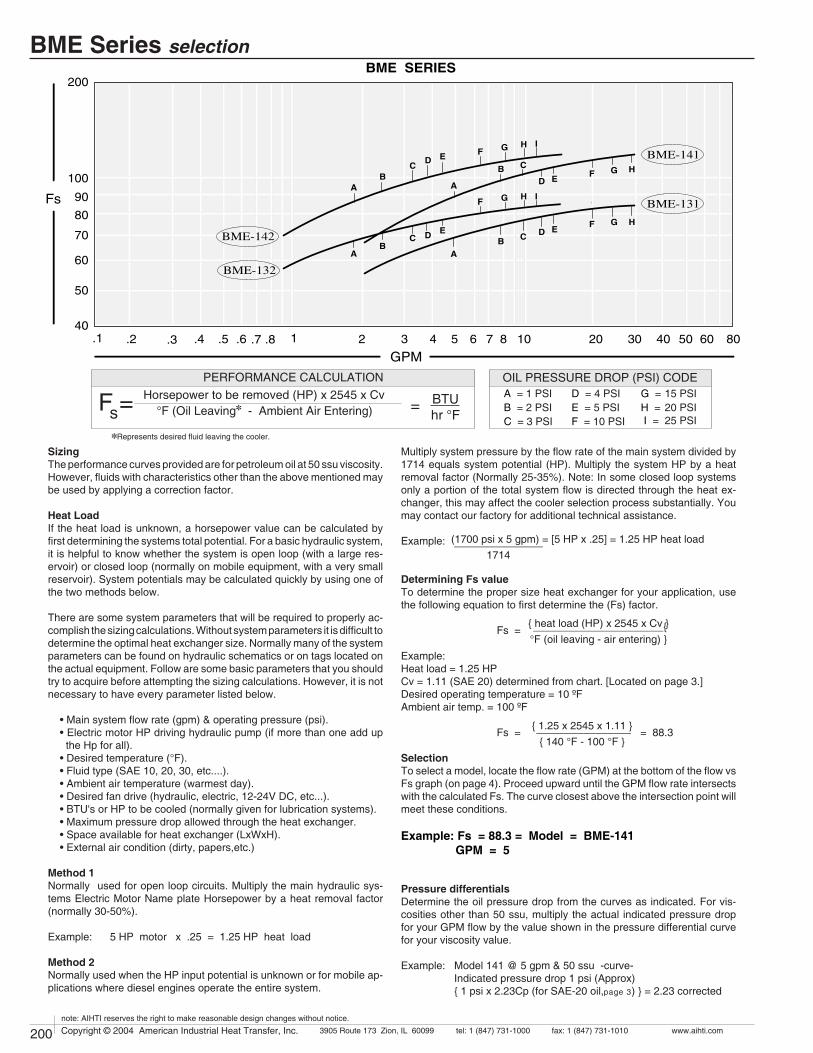
200 Copyright © 2004 American Industrial Heat Transfer, Inc. tel: 1 (847) 731-10003905 Route 173 Zion, IL 60099 www.aihti.comfax: 1 (847) 731-1010
note: AIHTI reserves the right to make reasonable design changes without notice.
201Copyright © 2004 American Industrial Heat Transfer, Inc. tel: 1 (847) 731-10003905 Route 173 Zion, IL 60099 www.aihti.comfax: 1 (847) 731-1010
note: AIHTI reserves the right to make reasonable design changes without notice.
BME-142
BME-141
BME-131
BME-132
200
100
90
80
70
60
50
40.2.1 1.3 .4 .5 .6 .7 .8 2 3 4 5 6 7 8 10 20 30 40 50 60 80
BME SERIES
GPM
Fs
BB C
A A
CD E F G H I
AB C D E
F G H
D EF G H
EDCB
A
F G H I
SizingThe performance curves provided are for petroleum oil at 50 ssu viscosity. However, fluids with characteristics other than the above mentioned may be used by applying a correction factor.
Heat LoadIf the heat load is unknown, a horsepower value can be calculated by first determining the systems total potential. For a basic hydraulic system, it is helpful to know whether the system is open loop (with a large res-ervoir) or closed loop (normally on mobile equipment, with a very small reservoir). System potentials may be calculated quickly by using one of the two methods below.
There are some system parameters that will be required to properly ac-complish the sizing calculations. Without system parameters it is difficult to determine the optimal heat exchanger size. Normally many of the system parameters can be found on hydraulic schematics or on tags located on the actual equipment. Follow are some basic parameters that you should try to acquire before attempting the sizing calculations. However, it is not necessary to have every parameter listed below.
• Main system flow rate (gpm) & operating pressure (psi). • Electric motor HP driving hydraulic pump (if more than one add up
the Hp for all). • Desired temperature (°F). • Fluid type (SAE 10, 20, 30, etc....). • Ambient air temperature (warmest day). • Desired fan drive (hydraulic, electric, 12-24V DC, etc...). • BTU's or HP to be cooled (normally given for lubrication systems). • Maximum pressure drop allowed through the heat exchanger. • Space available for heat exchanger (LxWxH). • External air condition (dirty, papers,etc.)
Method 1Normally used for open loop circuits. Multiply the main hydraulic sys-tems Electric Motor Name plate Horsepower by a heat removal factor (normally 30-50%).
Example: 5 HP motor x .25 = 1.25 HP heat load
Method 2Normally used when the HP input potential is unknown or for mobile ap-plications where diesel engines operate the entire system.
Multiply system pressure by the flow rate of the main system divided by 1714 equals system potential (HP). Multiply the system HP by a heat removal factor (Normally 25-35%). Note: In some closed loop systems only a portion of the total system flow is directed through the heat ex-changer, this may affect the cooler selection process substantially. You may contact our factory for additional technical assistance.
Example:
Determining Fs valueTo determine the proper size heat exchanger for your application, use the following equation to first determine the (Fs) factor.
Fs =
Example: Heat load = 1.25 HP Cv = 1.11 (SAE 20) determined from chart. [Located on page 3.] Desired operating temperature = 10 ºFAmbient air temp. = 100 ºF
Fs = = 88.3
SelectionTo select a model, locate the flow rate (GPM) at the bottom of the flow vs Fs graph (on page 4). Proceed upward until the GPM flow rate intersects with the calculated Fs. The curve closest above the intersection point will meet these conditions.
Example: Fs = 88.3 = Model = BME-141 GPM = 5
Pressure differentialsDetermine the oil pressure drop from the curves as indicated. For vis-cosities other than 50 ssu, multiply the actual indicated pressure drop for your GPM flow by the value shown in the pressure differential curve for your viscosity value.
Example: Model 141 @ 5 gpm & 50 ssu -curve- Indicated pressure drop 1 psi (Approx) { 1 psi x 2.23Cp (for SAE-20 oil,page 3) } = 2.23 corrected
(1700 psi x 5 gpm) = [5 HP x .25] = 1.25 HP heat load _______________ 1714
{ heat load (HP) x 2545 x Cv } ______________________{ °F (oil leaving - air entering) }
{ 1.25 x 2545 x 1.11 } ________________{ 140 °F - 100 °F }
BME Series selection
]Represents desired fluid leaving the cooler.
Horsepower to be removed (HP) x 2545 x Cv °F (Oil Leaving] - Ambient Air Entering) Fs =
OIL PRESSURE DROP (PSI) CODE
BTUhr °F
=
PERFORMANCE CALCULATIOND = 4 PSIE = 5 PSIF = 10 PSI
G = 15 PSIH = 20 PSI I = 25 PSI
A = 1 PSIB = 2 PSIC = 3 PSI

200 Copyright © 2004 American Industrial Heat Transfer, Inc. tel: 1 (847) 731-10003905 Route 173 Zion, IL 60099 www.aihti.comfax: 1 (847) 731-1010
note: AIHTI reserves the right to make reasonable design changes without notice.
201Copyright © 2004 American Industrial Heat Transfer, Inc. tel: 1 (847) 731-10003905 Route 173 Zion, IL 60099 www.aihti.comfax: 1 (847) 731-1010
note: AIHTI reserves the right to make reasonable design changes without notice.
BME-131 Thru BME-141
EXAMPLE OF A MODEL
FB
J P M
Q
G
L
C
H
NA
D
K
HFB
PM
Q
L
C
J
N
D
A
G0.34 DIA.MountingHoles (2x)
EE
MODEL BME-131, MODEL BME-141 (SINGLE PASS )# MODEL BME-132, MODEL BME-142 ( TWO PASS )#
BME - 142 - S
SeriesModel
Connections
N = NPTS = SAE
PIPING HOOK UP
Tubes Copper
Fins Aluminum
Turbulators Steel
Manifold Steel
Mount. bracket Steel
Cabinet Steel
Fan Blade Aluminum
Standard Construction Materials
STANDARD CONSTRUCTION MATERIALS
Operating Pressure 300 psig
Operating Temp. 400 oF
Standard Unit Ratings
ELECTRIC MOTOR DATA
115
115
115
115
BME - 131
BME - 132
BME - 141
BME - 142
1.1
1.1
1.12
1.12
1
1
1
1
AUTO
AUTO
AUTO
AUTO
1 / 40
1 / 40
1 / 40
1 / 40
60
60
60
60
1550
1550
3000
3000
T.E.A.O.
T.E.A.O.
T.E.A.O.
T.E.A.O.
ThermalOverloadRPMHzPhase Volts Full Load
AmperesHorsePowerModel Enclosure
Type
BM-131 & BM-141(Side Ports)(Single Pass)
BM-132 & BM-142(Back Ports)(Two Pass)
Model
BME - 131
BME - 132
BME - 141
BME - 142
J PMLKGENPT
FDCBA H
STANDARD DIMENSIONS (inches)
10.25 2.229.0015.75 5.88
7.75
2.69
7.75
2.69
.75 7.00 7.50 10.50 2.31
.94
6.00
.94
6.00
WeightLBS
18.50
1.13
–
1.13
–
N
0.75
Q
8.50
E
#12
SAE
BME Series dimensions & motor data
Adjustablebrackets
OUT
IN
IN or OUTIN or OUT
Fan rotation
Adjustablebrackets
OUT
IN
IN or OUTIN or OUT
Fan rotation

202 Copyright © 2004 American Industrial Heat Transfer, Inc. tel: 1 (847) 731-10003905 Route 173 Zion, IL 60099 www.aihti.comfax: 1 (847) 731-1010
note: AIHTI reserves the right to make reasonable design changes without notice.
203Copyright © 2004 American Industrial Heat Transfer, Inc. tel: 1 (847) 731-10003905 Route 173 Zion, IL 60099 www.aihti.comfax: 1 (847) 731-1010
note: AIHTI reserves the right to make reasonable design changes without notice.
BME Series installation & maintenanceReceiving / Installationa) Inspect unit for any shipping damage before uncrating. Indicate all damages to the trucking firms' delivery person and mark it on the receiving bill before accepting the freight. Make sure that the core and fan are not damaged. Rotate the fan blade to make sure that it moves freely. Since the warranty is based upon the unit date code located on the model identification tag, removal or manipulation of the identification tag will void the manufacturers warranty.
c) Standard Enamel Coating: American Industrial provides its standard products with a normal base coat of oil base air cure enamel paint. The enamel paint is applied as a temporary protective and esthetic coating prior to shipment. While the standard enamel coating is durable, American Industrial does not warranty it as a long-term finish coating. It is strongly suggested that a more durable final coating be applied after installation or prior to long-term storage in a corrosive environment to cover any accidental scratches, enhance esthetics, and further prevent corrosion. It is the responsibility of the customer to provide regular maintenance against chips, scratches, etc... and regular touch up maintenance must be provided for long-term benefits and corrosion prevention.
d) Special Coatings: American Industrial offers as customer options, Air-Dry Epoxy, and Heresite (Air-Dry Phenolic) coatings at additional cost. American Industrial offers special coatings upon request, however American Industrial does not warrantee coatings to be a permanent solution for any equipment against corrosion. It is the responsibility of the customer to provide regular maintenance against chips, scratches, etc... and regular touch up maintenance must be provided for long-term benefits and corrosion prevention.
e) American Industrial recommends that the equipment supplied should be installed by qualified personnel who have solid understanding of system design, pressure and temperature ratings, and piping assembly. Verify the service conditions of the system prior to applying any air cooled heat exchanger series cooler. If the system pressure or temperature does not fall within the parameters on model rating tag located on the heat exchanger, contact our factory prior to installation or operation.
g) Heat exchanger should be securely fastened using the mounting foot brackets (included). All mounting holes should be used to secure unit into place.
h) Connections should be made in "one pass" or "two pass" configurations exactly as indicated in the "piping hook up" illustration. The process flow entering the "Fluid IN" port and exiting the "Fluid OUT" port eliminates air pockets and assures that the unit will stay completely flooded. Flexible hose can be applied to reduce the risk of core failure due to thermal ex-pansion or system vibration. Piping alignment and support is required for hoses longer than four feet in length and for piping exerting more than 10 lbs of dynamic force. It is recommended that filtration be located ahead of the heat exchanger to prevent excessive backpressure and clogging.
i) With respect to the heat exchangers nozzle size, flow line sizes should be sized to handle the appropriate flow rate and system pressure drop requirements, normally flow line rates of about 8-12 feet per second and inlet pressure less than 100psig are experienced. If the flow line size is larger than the heat exchanger nozzle size, additional pressure loss beyond the published pressure loss data may occur.
j) Electric motors should be connected only to supply source of the same characteristics as indicated on the electric motor information plate. Prior to starting, verify that the motor and fan spin freely without obstruction. Check carefully that the fan turns in the correct rotation direction (normally counter clockwise) from the motor side (fan direction arrow). Failure to operate the fan in the proper direction could reduce performance or cause serious damage to the heat exchanger or other components.
k) Solely at the request of customers, American Industrial provides direct acting internal inlet port to outlet port bypass relief valves as an addi-tional safe guard against excessive flow and over pressurization of the heat exchanger. American Industrial purchases and applies high quality hydraulic system cartridge valves and components made available for hydraulic system use. However, American Industrial does not specify, recommend, suggest, guarantee, or warrantee the internal relief valve or its performance to safe guard the heat exchanger from damage or prevent failure due to excessive flow or over pressurization. It is the ultimately the sole responsibility of the customer/user to verify with the original equipment manufacture all conditions associated with applying an additional system relief valve prior to application.
MaintenanceRegular maintenance intervals based upon the surrounding and opera-tional conditions should be maintained to verify equipment performance and to prevent premature component failure. Since some of the compo-nents such as, motors, fans, etc... are not manufactured by American Industrial, maintenance requirements provided by the manufacture must be followed.
a) Inspect the entire heat exchanger and motor/fan assembly for loosened bolts, loose connections, broken components, rust spots, corrosion, fin/coil clogging, or external leakage. Make immediate repairs to all affected areas prior to restarting and operating the heat exchanger or its components.
b) Heat exchangers operating in oily or dusty environments will often need to have the coil cooling fins cleaned. Oily or clogged fins should be cleaned by carefully brushing the fins and tubes with water or a non-ag-gressive degreasing agent mixture (Note: Cleaning agents that are not compatible with copper, brass, aluminum, steel or stainless steel should not be used). A compressed air or a water stream can be used to dislodge dirt and clean the coil further. Any external dirt or oil on the electric motor and fan assembly should be removed. Caution: Be sure to disconnect the electric motor from its power source prior to doing any maintenance.
c) In most cases it is not necessary to internally flush the coil. In circum-stances where the coil has become plugged or has a substantial buildup of material, flushing the coil with water or a solvent may be done. Flush-ing solvents should be non-aggressive suitable for the materials of con-struction. Serviceable Core® models can be disassembled and inspected or cleaned if required.
e) Fan blades should be cleaned and inspected for tightness during the regular maintenance schedule when handling a fan blade care must be given to avoid bending or striking any of the blades. Fan blades are fac-tory balanced and will not operate properly if damaged or unbalanced. Damaged fan blades can cause excessive vibration and severe damage to the heat exchanger or drive motor. Replace any damaged fan with an American industrial suggested replacement.
f) Air cooled exchanger cabinets are constructed using 7ga. through 18ga. steel that may be bent back into position if damaged. Parts that are not repairable can be purchased through American Industrial.
g) Coil fins that become flattened can be combed back into position. This process may require removal of the coil from the cabinet.
h) It is not advisable to attempt repairs to brazed joints of a brazed construction coil unless it will be done by an expert in silver solder braz-ing. Brazed coils are heated uniformly during the original manufacturing process to prevent weak zones from occurring. Uncontrolled reheating of the coil may result in weakening of the tube joints surrounding the repair area. In many instances brazed units that are repaired will not hold up as well to the rigors of the system as will a new coil. American Industrial will not warranty or be responsible for any repairs done by unauthorized sources. Manipulation in any way other than normal application will void the manufactures warranty.

144 Copyright © 2004 American Industrial Heat Transfer, Inc. tel: 1 (847) 731-10003905 Route 173 Zion, IL 60099 www.aihti.comfax: 1 (847) 731-1010
note: AIHTI reserves the right to make reasonable design changes without notice.
145Copyright © 2004 American Industrial Heat Transfer, Inc. tel: 1 (847) 731-10003905 Route 173 Zion, IL 60099 www.aihti.comfax: 1 (847) 731-1010
note: AIHTI reserves the right to make reasonable design changes without notice.
Insulation of boileror storage tank
Capillarytubing
Tube Clip &rubber gromet
1/2"-14 external threads on spud
Wall or boiler orstorage tank
ImmersionWall
Sensing Bulb
Spud screws into tapping (reducer fitting may be
necessary to adapt spudto tapping)
Sensing Bulb
Composition Disc(slotted)
Packing Nut
Screws into tappingin boiler or tank
Slotted brass washersassembled in pairs
1/2" Capillarycompression fitting
1/2"-14 Externalthreads on spud
CapillaryTubing
ELECTRICAL TEMPERATURE CONTROLLER WITH BULB WELL ASSEMBLY (for Air/Oil Coolers)
0.20
2.13
2.25
2.44
2.63
1.220.38
0.94
ø0.88 Knockout Both ends
2.00
ø0.22 (3x)ø0.37 (3x)
4.19
0.69
5.63
1.75
1.94
SPECIFICATIONS:A) Material: CopperB) Power Limits: 1)For three phase motor operation, use only with a magnetic starter, 125 VA max. (VA =volts x amps) 2)For pilot duty, 125 VA max. 3)For direct connection to motor: 120v AC/8.0 amps max 230v AC/5.1 amps max 277v AC/4.2 amps max 460v AC/2.0 amps max 4)Temperature operating range: 55°F to 175°F.
APPLICATIONS (Temperature Controller) The TC511 temperature controllers are designed to control the temperature of air or liquids in ducts, pipes, tanks, and boilers. Typical uses include control of dampers and valves in heating, cooling, or heating-cooling systems. The TC511 has 1 spdt switch. It makes or breaks a circuit on a change in temperature at the sensing bulb. Fast response models with adjustable differential are available for duct installation. They respond approximately 4 times faster than standard models.
INSTALLATIONWhen installing this product:1. Read instructions carefully. Failure to follow the instructions could damage the
product or cause a hazardous condition.2. Check the ratings given in the instructions and on the product to make sure the
product is suitable for your application.3. Installer must be a trained, experienced service technician.4. After installation is complete, check out product operation as provided in the
instructions.
ELECTRICAL RATINGS:TC511 models with adjustable differential:TC511 models with fixed differential -125 VA at 120/208/240/277 Vac.MAXIMUM BULB PRESSURE: 50 psi (344.7 kPa) for direct immersions.
LOCATION AND MOUNTING. The controller may be installed in any convenient position. Mount it with 3 screws through the slotted holes in the back of the case. Be sure to consider the length of the capillary before mounting the controller. Install the sensing element where it is exposed to the average temperature of the controlled medium. The sensing bulb may be directly immersed or mounted in a well. Fast response models must use the capillary holder furnished with the device. The remote sensing bulb of standard models should be held in place with a capillary holder, immersion well, or compression fitting. Sharp bends or kinks in the capillary tubing affect the efficiency of the controller and must be avoided. Excess capillary should be carefully coiled and left directly beneath the controller.NOTE: When pressure fittings are used in areas of vibration (such as pipe lines) the bulb must be adequately supported.
OPERATION As the temperature of the controlled medium falls below the set point less differential, the TC511 switch makes terminal R to B and energizes a normally close solenoid valve to provide heat. In cooling applications, the TC511 makes terminal R to W as the temperature rises above the set point, energizing cooling equipment.
ACCESSORIES air / oil heat exchangers
Part Number Description310-4001 TC-511 with 5-Foot Capallary Tube & Bulb Well310-4002 TC-511 with 20-Foot Capallary Tube & Bulb Well310-2005 Replacement Bulb Well TC-511
Length for 3/4" - 1 1/4"9.5"
Length for 1/2" - 3/8"5.5"

188 Copyright © 2004 American Industrial Heat Transfer, Inc. tel: 1 (847) 731-10003905 Route 173 Zion, IL 60099 www.aihti.comfax: 1 (847) 731-1010
note: AIHTI reserves the right to make reasonable design changes without notice.
189Copyright © 2004 American Industrial Heat Transfer, Inc. tel: 1 (847) 731-10003905 Route 173 Zion, IL 60099 www.aihti.comfax: 1 (847) 731-1010
note: AIHTI reserves the right to make reasonable design changes without notice.
Part NumberDescription
Part NumberDescription
Temp. Setting Size NPT Temp. Setting Size NPT310-7029 100 OF
1/2”
310-7014 100 OF
1-1/2”310-7023 110 OF 310-7034 110 OF310-7030 120 OF 310-7035 120 OF310-7043 140 OF 310-7012 140 OF310-7006 160 OF 310-7001 160 OF310-7031 100 OF
3/4”
310-7002 100 OF
2”310-7032 110 OF 310-7024 110 OF310-7022 120 OF 310-7036 120 OF310-7042 140 OF 310-7020 140 OF310-7007 160 OF 310-7010 160 OF310-7033 100 OF
1”
310-7037 100 OF
3”310-7026 110 OF 310-7038 110 OF310-7028 120 OF 310-7039 120 OF310-7021 140 OF 310-7041 140 OF310-7008 160 OF 310-7040 160 OF
“3-Way” Thermostatic Valve
Part Number Description310-4001 TC-511 with 5-Foot Capallary Tube & Bulb Well310-4002 TC-511 with 20-Foot Capallary Tube & Bulb Well310-2005 Replacement Bulb Well TC-511
Adjustable Electrical Temperature Switch (see page 224)
Thermostatic valves utilize the principle of expanding wax, which in the semi-liquid state undergoes large expansion rates within a relative-ly narrow temperature range. The self contained power element activates a stainless steel sliding valve which provides positive three-way actions. All thermostatic valves are factory set at prede-termined temperatures; no further adjustments are necessary. A wide range of temperatures are available for water and oil temperature control ap-plications. On starting, the total fluid flow is in a by-pass mode. As fluid temperature rises to the control range some fluid is diverted to the cooling system. As fluid temperature continues to in-crease, more flow is diverted, and when in a fully stroke condition all fluid flow is positively directed to the cooling system. Thermostatic valves may be used for either mixing or diverting applications. In normal operation fluid temperatures are con-trolled to within a few degrees. Standard thermostatic valve housings are made from high quality grey iron castings.
ACCESSORIES air / oil heat exchangers
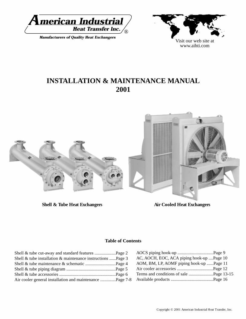
Copyright © 2001 American Industrial Heat Transfer, Inc.
Shell & Tube Heat Exchangers Air Cooled Heat Exchangers
Visit our web site atwww.aihti.com
®
INSTALLATION & MAINTENANCE MANUAL2001
Shell & tube cut-away and standard features ...................Page 2Shell & tube installation & maintenance instructions ......Page 3Shell & tube maintenance & schematic ...........................Page 4Shell & tube piping diagram ............................................Page 5Shell & tube accessories ..................................................Page 6Air cooler general installation and maintenance ..............Page 7-8
Table of Contents
AOCS piping hook-up ................................Page 9AC, AOCH, EOC, ACA piping hook-up ....Page 10AOM, BM, LP, AOMF piping hook-up ......Page 11Air cooler accessories ................................Page 12Terms and conditions of sale ......................Page 13-15Available products ......................................Page 16

Copyright © 2001 American Industrial Heat Transfer, Inc.
1- MOUNTING BRACKETHeavy gauge steel mounting brackets are adjustable inorientations to 360 degrees.
2- BONNETProvides fluid into tubes with minimum restriction. One,two, or four pass interchangeability.
3- FLOW CAVITYGenerously sized to allow for minimum pressure dropand more uniform flow.
4- TUBES JOINTRoller expanded tube joint to integral forged hub.
5- TUBES SHEETPrecision-machined tube-sheet provides for long last-ing high strenght service.
6- THREADCNC precision threading to provide accurate leakproofconnections.
7- BAFFLESCNC manufactured baffles to provide maximum turbu-lence and heat transfer with a minimum fluid pressuredrop.
8- FINISHGray semigloss enamel suitable for outdoor service.Can be used as a base for additional coats.
9- SHELL & TUBE BUNDLE ASSEMBLYCNC precision manufactured parts to guarantee a closefit between the baffles, tubes, and shell. Clearances areminimized to provide for maximum heat transfer.
10- HUBPremium quality forging with full opening designedfor minimum pressure drop.
11- FULL FACE GASKETFull-face composite gasket for maximum pressureand temperature.
12- DRAIN PORTDrain ports allow for easy draining of tube side.Optional zinc anode can be inserted in place of plug.
Note: Standard Feature descriptions are qualified byand subject to product specifications which are avail-able from American Industrial upon request.
1
2
3
4
67
8
9
10
11
12
1
23
4
6 7
9
10
11
12
8
1
2
3
4
6 7
8
9
11
12
AB , AB-2000, SAE, STS & EABSERIES
AA , STA & FBFSERIES
CS , STC & CKSERIES
SHELL & TUBE HEAT EXCHANGERS STANDARD FEATURES
5
2
Copyright © 2001 American Industrial Heat Transfer, Inc.
SHELL & TUBE GENERAL INSTALLATION & MAINTENANCE
Receivinga) Inspect unit for any shipping damage before uncrating. Indicateall damages to the trucking firms' delivery person, and mark it onthe receiving bill before accepting the freight. Make sure that thereis no visible damage to the outside surface of the heat exchanger.Since the warranty is based upon the unit date code located on themodel identification tag, removal or manipulation of the identifi-cation tag will void the manufacturers warranty.
b) When handling the shell & tube heat exchanger, special careshould be taken to avoid dropping the unit since mishandling couldcause the heat exchanger to crack and leak externally. Mishandlingof the unit is not covered under the manufacturers warranty. Allunits are shipped with partial wood/corrugated cardboard contain-ers for safe handling.
c) Standard Enamel Coating: American Industrial provides its stan-dard products with a normal base coat of oil base air cure enamelpaint. The enamel paint is applied as a temporary protective andesthetic coating prior to shipment. While the standard enamel coat-ing is durable, American Industrial does not warranty it as a long-term finish coating. It is strongly suggested that a more durablefinal coating be applied after installation or prior to long-term stor-age in a corrosive environment to cover any accidental scratches,enhance esthetics, and further prevent corrosion. It is the responsi-bility of the customer to provide regular maintenance against chips,scratches, etc... and regular touch up maintenance must be pro-vided for long-term benefits and corrosion prevention.
d) Special Coatings: American Industrial offers as customer op-tions, Air-Dry Epoxy, and Heresite (Air-Dry Phenolic) coatings atadditional cost. American Industrial offers special coatings uponrequest, however American Industrial does not warrantee coatingsto be a permanent solution for any equipment against corrosion. Itis the responsibility of the customer to provide regular maintenanceagainst chips, scratches, etc... and regular touch up maintenancemust be provided for long-term benefits and corrosion prevention.
Installationa) American Industrial recommends that the equipment suppliedshould be installed by qualified personnel who have solid under-standing of system design, pressure and temperature ratings, andpiping assembly. Verify the service conditions of the system priorto applying any shell & tube heat exchanger. If the system pressureor temperature does not fall within the parameters on model ratingtag located on the heat exchanger, contact our factory prior to in-stallation or operation.
b) Plan the installation to meet the requirements indicated on thepiping installation diagram as illustrated (page 4). It is recommendedto put the hot fluid to be cooled through the shell side and the coldfluid through the tube side. The indicated port assembly sequencein the diagram maximizes the performance, and minimizes the pos-sibility of thermal shock. In instances where the fluids are requiredto be reversed, hot fluid in the tubes and cold fluid in the shell theheat exchanger will work with reduced performance.
c) When installing a series EAB heat exchanger (expansion bel-
low), it is recommended to use a shoulder bolt to allow the heatexchanger to move freely while expanding and contracting due tohigh differential temperatures.
d) It is recommended to use flexible hose wherever possible toreduce vibration and allow slight movement. However, hoses arenot required. Hydraulic carrying lines should be sized to handlethe appropriate flow and to meet system pressure drop require-ments based upon the systems parameters, and not based upon theunits supply and return connection size. We recommend that a lowcracking pressure direct acting relief valve be installed at the heatexchanger inlet to protect it from pressure spikes by bypassing oilin the event the system experiences a high flow surge. If preventa-tive filtration is used it should be located ahead of the cooler onboth shell and tube side to catch any scale or sludge for the systembefore it enters the cooler. Failure to install filters ahead of the heatexchanger could lead to possible heat exchanger failure due to highpressure if the system filters plug.
e) Standard shell & tube coolers are built with a rolled tube-sheetconstruction. However, the differential operating temperature be-tween the entering shell side fluid and the entering tube side fluidshould not exceed 150°F. If this condition exists, a severe thermalshock could occur leading to product failure and mixing of thefluids. For applications with a differential temperatures of 150°For more, we recommend using a series with a floating tube-sheet,u-tube, or expansion joint to reduce the potential for the effects ofthermal shock.
g) Water requirements vary from location to location. If the sourceof cooling water is from other than a municipal water supply, it isrecommended that a water strainer be installed ahead of the heatexchanger to prevent dirt and debris from entering and cloggingthe flow passages. If a water modulating valve is used it is recom-mended to be installed at the inlet to the cooler to regulate thewater flow.
h) For steam service, or other related applications, please consultour engineering department for additional information.
Maintenancea) Inspect the heat exchanger for loosened bolts, connections, rustspots, corrosion, and for internal or external fluid leakage. Anycorroded surfaces should be cleaned and recoated with paint.
b) Shell side: In many cases with clean hydraulic system oils it willnot be necessary to flush the interior of the shell side of the cooler.In circumstances where the quality of hydraulic fluid is in ques-tion, the shell side should be disconnected and flushed on a yearlybasis with a clean flushing oil/solvent to remove any sludge thathas been deposited. For severe cases where the unit is plugged andcannot be flushed clean with solvent, the heat exchanger should bereplaced to maintain the proper cooling performance.
c) Tube side: In many cases it will be necessary to clean the tubeside of the heat exchanger due to poor fluid quality, debris, cal-cium deposits, corrosion, mud, sludge, seaweed, etc.... To clean
3

Copyright © 2001 American Industrial Heat Transfer, Inc.
the tube side, flush with clean water or any good quality commer-cial cleaner that does not attack the particular material of construc-tion. With straight tube heat exchangers you can use a rod to care-fully push any debris out of the tubes.
d) Zinc anodes are normally used to reduce the risk of failure dueto electrolysis. Zinc anodes are a sacrificial component designedto wear and dissolve through normal use. Normally, zinc anodesare applied to the water supply side of the heat exchanger. Depend-ing upon the amount of corrosive action, one, two, three, or moreanodes can be applied to help further reduce the risk of failure.American Industrial Heat Transfer, Inc. offers zinc anodes as anoption, to be specified and installed at the request our customers. Itis the responsibility of the customer to periodically check and verifythe condition of the zinc anode and replace it as needed.
Applications vary due to water chemical makeup and quality, ma-terial differences, temperature, flow rate, piping arrangements, andmachine grounding. For those reasons, zinc anodes do not followany scheduled factory predetermined maintenance plan moreoverthey must be checked routinely by the customer, and a mainte-nance plan developed based upon the actual wear rate.
If substantial wear occurs or zinc dissolves without replacement,premature failure or permanent damage may occur to the heat ex-changer. American Industrial does not warranty customer applica-tions. It is the responsibility of the customer to verify and apply theproper system materials of construction and overall system require-ments. Failures resulting from properly applied or misapplied useof zinc anode(s) into non-specified or specified applications willbe the sole responsibility of the customer.
e) A routine maintenance schedule should be developed and ad-justed to meet your systems requirements based upon water qual-ity, etc….Failure to regularly maintain and clean your heat ex-changer can result in a reduction in operational performance andlife expectancy.
SHELL & TUBE GENERAL INSTALLATION & MAINTENANCE
3/8" NPT Thread
1.84"
1.00"
0.86" 0.50"ø
0.75"
1/2" NPT Thread
2.70"
1.15" 0.63"ø
1.00" 1.75"
3/8" NPT Zinc AnodePN: 301-0004
AB-400 thru AB-1000AA-400 thru AA-1000CS-600 thru CS-1000
1/2" NPT Zinc AnodePN: 301-0003
AB-1200 thru AB-2000AA-1200 thru AA-1600CS-1200 thru CS-1700
Return Line
Relief Valve
Return LineFilter
HeatExchanger
Y Strainer Water Modulating Valve
To Tower
Or Drain
TUBE SIDE PASSES
The number of passes (SP,TP &FP) refers to the number of runsback and forth of the cooling fluid on the tube side of the heatexchanger. Tube passes are normally determined by the rate (gpm)of water available to be used for cooling purposes (see table E).The purpose of multi-passes are to increase turbulence by increas-ing the velocity. Normally tube side passes will not affect pricing.
TABLE E - Flow Rate for Tube SideShell Liquid Flow - Tube Side
dia . SP TP FP
Code Min. Max. Min. Max. Min. Max.
400 3.5 21 –– –– –– ––
600 7.5 48 3.5 24 2 12
700 9 61 4.5 30 2.2 15
800 10 50 4.5 38 3 21
1000 20 120 10 70 5.0 37
1200 30 250 15 112 7.5 56
1600 57 460 29 180 14 90
1700 57 300 29 180 14 90
2000 90 650 45 320 25 160
TYPICAL HYDRAULIC CIRCUIT
with water cooled heat exchanger
4

Copyright © 2001 American Industrial Heat Transfer, Inc.
SHELL & TUBE PIPING HOOK-UP
URCSR SeriesUCSR Series
Vent Port
Condensate out
Steam In
Fluid Out
Fluid In
Mounting
Air Out
Water In
Water Out
Drain Port
Air In
Mounting(Both Sides)
C
B
B
B
A
A
A
D
D
D
CC
C
B
B
B
A
A
A
D D
C D
C
ONE PASS TWO PASS FOUR PASS
A .......... Hot fluid to be cooledB ......................... Cooled fluidC .................. Cooling water inD ................ Cooling water out
SP ......................... Single PassTP ............................. Two PassFP ............................ Four Pass
AB SeriesSAE SeriesEAB SeriesSTS SeriesSRAB SeriesUAB SeriesURAB Series
AA SeriesSTA SeriesCS SeriesSTC SeriesCK SeriesSRCS SeriesURCS Series
ONE PASS TWO PASS FOUR PASS
ABR Series
5

Copyright © 2001 American Industrial Heat Transfer, Inc.
SHELL & TUBE ACCESSORIES
APPLICATIONS & SPECS. ("Y" Strainers)These strainers are engineered for water or steam, and are adaptable for many other uses. Cleaning is accomplished by simply removing a pipeplug without disconnecting any piping. Or, if it is desirable to clean without interrupting service, a blow-off valve can be connected to theclean-out opening. Note: Pumps, control valves, traps, or other equipment controlling the flow of liquids or gases require proper protectionwith strainers for trouble free operation.
18 - Y BRASS STRAINERSThe 18 - Y strainer body is a red brass casting. Standard units have 50 mesh brass wire screens. Brazing connections are available on specialorder instead of pipe threads.
20 - Y STRAINERSThe 20 - Y strainer has a heavy cast iron body with machined pipe thread inlet and outlet (National Pipe Thread N.P.T.). It contains a strainerscreen of 0.02" thick brass with 100, 1/16" perforations per inch.
�������������������������������������������������
C
D
APipe Thread
INLET
OUTLET
EClean-outOpening
Pipe Thread
B
MODELSIZE
A(NPT)
DIMENSIONS (Inches) WT.(lbs.)B C D
E(NPT)
18 - Y
0.38"0.50"0.75"1.00"
2.50"2.50"3.50"3.50"
2.63"2.63"3.75"3.75"
2.00"2.00"2.75"2.75"
0.25"0.25"0.50"0.50"
0.750.751.751.75
20 - Y
0.50"0.75"1.00"1.25"1.50"2.00"
4.00"4.00"4.75"6.00"6.00"8.13"
3.25"3.25"4.38"5.13"5.13"6.38"
2.50"2.50"3.38"3.88"3.88"4.63"
0.38"0.38"0.75"0.75"0.75"0.75"
1.751.754.004.754.75
13.00
PRESSURE RATINGS, ALL MODELS: 125lbs. per Sq.In.
"Y" STRAINER (for Shell & Tube Heat Exchangers And Air/Oil Coolers)
THERMOSTATIC MODULATING WATER VALVE WITH BULB WELL ASSEMBLY(for Shell & Tube Heat Exchangers And Air/Oil Coolers)
SPECIFICATIONS
Sizes 0.375", 0.50", 0.75", 1.00", 1.25" FPTFluid Pressure 125psi (max.)Standard Temperature 40° - 100° F., 60° - 140° F., 100° - 175° F., 125° - 200° F.,
140° - 240° F., 200° - 275°F.Body Brass alloy castingValve Parts Brass alloyStandard Capillary Length 6’ & 20’ footStandard Bulbs For 3/8" & 1/2" valve sizes: 5/8" x 6 with 3/4" union
connections. For 3/4" & 1" valve sizes: 5/8" x 8-1/4"with 3/4" union connections.Stainless steel construction available.
Standard Bulb Mounting 3/4" NPTSeat Disk Buna-N-replaceableSeat Bead Stainless Steel - replaceable Water Valve
Durable BronzeTwo-ply Bellows (inside)
Armor-platedDouble BraidedCopper Capillary
Body andValve PartsAre Special Brass Alloy
Adjusting Cap For BetterTemperatureControl
CopperAlloy Bulb
APPLICATION INFORMATION• Built for machine tool and hydraulic applications.• Adjustable temperature range.• Response to temperature changes.• Direct acting bellows for longer service.Note: Please consult factory if a non-cataloged temperature is required.
The type 56-T valve gives smooth regulation of water and other fluids. It's designed for rugged application. For example: hydraulic powerpackaging equipment, hydraulic presses, plastic molding equipment, and anywhere reliability in temperature control is demanded.The type 56-T valve is a better designed product that won't leak or chatter. For dependability, every valve is factory tested three times indifferent temperature baths. They are direct acting with sturdy walls, and the inner spring is zinc coated. The seat beads are stainless steel toresist the erosive effects of wire drawing and provide durability for your needs. Additional features include mounting in any position, Buna-N seat disc, and manual flushing.
6
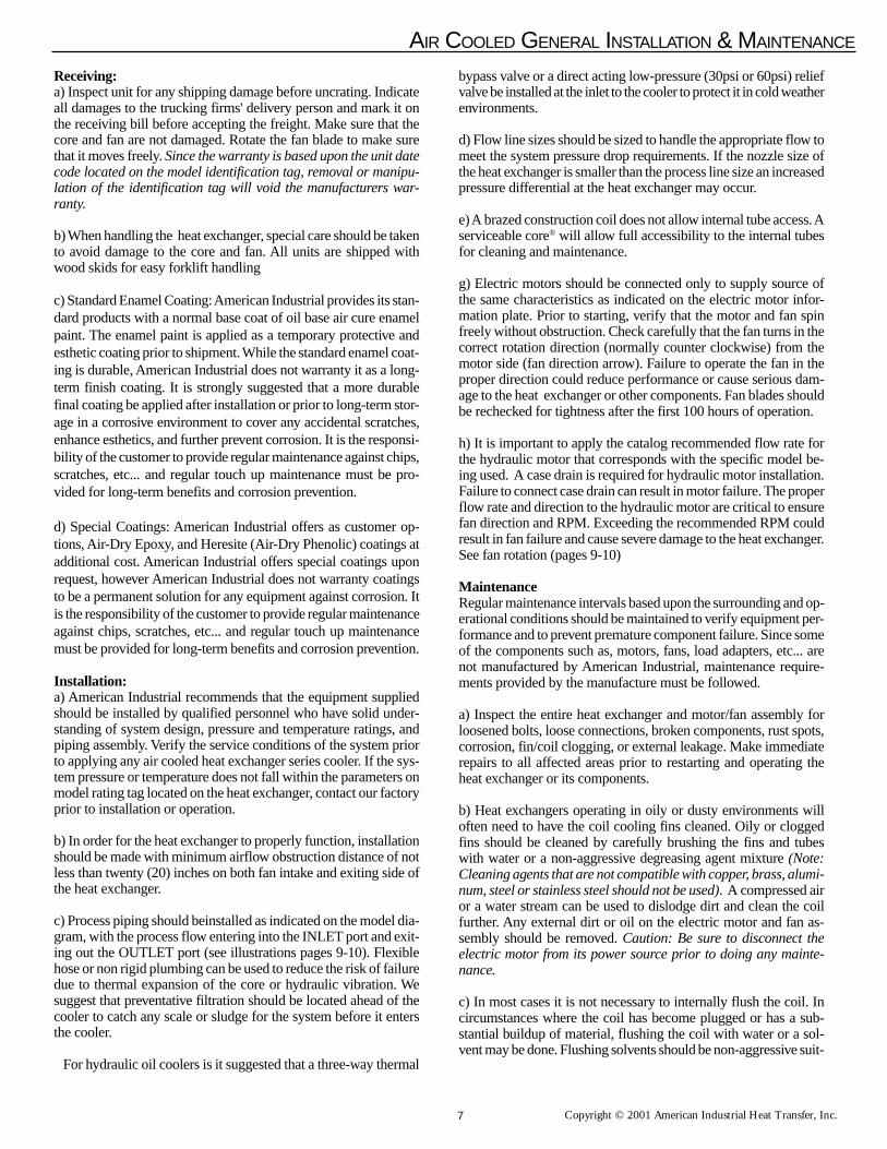
Copyright © 2001 American Industrial Heat Transfer, Inc.
AIR COOLED GENERAL INSTALLATION & MAINTENANCE
Receiving:a) Inspect unit for any shipping damage before uncrating. Indicateall damages to the trucking firms' delivery person and mark it onthe receiving bill before accepting the freight. Make sure that thecore and fan are not damaged. Rotate the fan blade to make surethat it moves freely. Since the warranty is based upon the unit datecode located on the model identification tag, removal or manipu-lation of the identification tag will void the manufacturers war-ranty.
b) When handling the heat exchanger, special care should be takento avoid damage to the core and fan. All units are shipped withwood skids for easy forklift handling
c) Standard Enamel Coating: American Industrial provides its stan-dard products with a normal base coat of oil base air cure enamelpaint. The enamel paint is applied as a temporary protective andesthetic coating prior to shipment. While the standard enamel coat-ing is durable, American Industrial does not warranty it as a long-term finish coating. It is strongly suggested that a more durablefinal coating be applied after installation or prior to long-term stor-age in a corrosive environment to cover any accidental scratches,enhance esthetics, and further prevent corrosion. It is the responsi-bility of the customer to provide regular maintenance against chips,scratches, etc... and regular touch up maintenance must be pro-vided for long-term benefits and corrosion prevention.
d) Special Coatings: American Industrial offers as customer op-tions, Air-Dry Epoxy, and Heresite (Air-Dry Phenolic) coatings atadditional cost. American Industrial offers special coatings uponrequest, however American Industrial does not warranty coatingsto be a permanent solution for any equipment against corrosion. Itis the responsibility of the customer to provide regular maintenanceagainst chips, scratches, etc... and regular touch up maintenancemust be provided for long-term benefits and corrosion prevention.
Installation:a) American Industrial recommends that the equipment suppliedshould be installed by qualified personnel who have solid under-standing of system design, pressure and temperature ratings, andpiping assembly. Verify the service conditions of the system priorto applying any air cooled heat exchanger series cooler. If the sys-tem pressure or temperature does not fall within the parameters onmodel rating tag located on the heat exchanger, contact our factoryprior to installation or operation.
b) In order for the heat exchanger to properly function, installationshould be made with minimum airflow obstruction distance of notless than twenty (20) inches on both fan intake and exiting side ofthe heat exchanger.
c) Process piping should beinstalled as indicated on the model dia-gram, with the process flow entering into the INLET port and exit-ing out the OUTLET port (see illustrations pages 9-10). Flexiblehose or non rigid plumbing can be used to reduce the risk of failuredue to thermal expansion of the core or hydraulic vibration. Wesuggest that preventative filtration should be located ahead of thecooler to catch any scale or sludge for the system before it entersthe cooler.
For hydraulic oil coolers is it suggested that a three-way thermal
bypass valve or a direct acting low-pressure (30psi or 60psi) reliefvalve be installed at the inlet to the cooler to protect it in cold weatherenvironments.
d) Flow line sizes should be sized to handle the appropriate flow tomeet the system pressure drop requirements. If the nozzle size ofthe heat exchanger is smaller than the process line size an increasedpressure differential at the heat exchanger may occur.
e) A brazed construction coil does not allow internal tube access. Aserviceable core® will allow full accessibility to the internal tubesfor cleaning and maintenance.
g) Electric motors should be connected only to supply source ofthe same characteristics as indicated on the electric motor infor-mation plate. Prior to starting, verify that the motor and fan spinfreely without obstruction. Check carefully that the fan turns in thecorrect rotation direction (normally counter clockwise) from themotor side (fan direction arrow). Failure to operate the fan in theproper direction could reduce performance or cause serious dam-age to the heat exchanger or other components. Fan blades shouldbe rechecked for tightness after the first 100 hours of operation.
h) It is important to apply the catalog recommended flow rate forthe hydraulic motor that corresponds with the specific model be-ing used. A case drain is required for hydraulic motor installation.Failure to connect case drain can result in motor failure. The properflow rate and direction to the hydraulic motor are critical to ensurefan direction and RPM. Exceeding the recommended RPM couldresult in fan failure and cause severe damage to the heat exchanger.See fan rotation (pages 9-10)
MaintenanceRegular maintenance intervals based upon the surrounding and op-erational conditions should be maintained to verify equipment per-formance and to prevent premature component failure. Since someof the components such as, motors, fans, load adapters, etc... arenot manufactured by American Industrial, maintenance require-ments provided by the manufacture must be followed.
a) Inspect the entire heat exchanger and motor/fan assembly forloosened bolts, loose connections, broken components, rust spots,corrosion, fin/coil clogging, or external leakage. Make immediaterepairs to all affected areas prior to restarting and operating theheat exchanger or its components.
b) Heat exchangers operating in oily or dusty environments willoften need to have the coil cooling fins cleaned. Oily or cloggedfins should be cleaned by carefully brushing the fins and tubeswith water or a non-aggressive degreasing agent mixture (Note:Cleaning agents that are not compatible with copper, brass, alumi-num, steel or stainless steel should not be used). A compressed airor a water stream can be used to dislodge dirt and clean the coilfurther. Any external dirt or oil on the electric motor and fan as-sembly should be removed. Caution: Be sure to disconnect theelectric motor from its power source prior to doing any mainte-nance.
c) In most cases it is not necessary to internally flush the coil. Incircumstances where the coil has become plugged or has a sub-stantial buildup of material, flushing the coil with water or a sol-vent may be done. Flushing solvents should be non-aggressive suit-
7

Copyright © 2001 American Industrial Heat Transfer, Inc.
AIR COOLED GENERAL INSTALLATION & MAINTENANCE
able for the materials of construction. Serviceable Core® modelscan be disassembled and inspected or cleaned if required.
d) Most low horsepower electric motors do not require any addi-tional lubrication. However, larger motors must be lubricated withgood quality grease as specified by the manufacture at least onceevery 6-9 months or as directed by the manufacture. T.E.F.C. airventilation slots should be inspected and cleaned regularly to pre-vent clogging and starving the motor of cooling air. To maintainthe electric motor properly see the manufactures requirements andspecifications.
e) Fan blades should be cleaned and inspected for tightness duringthe regular maintenance schedule when handling a fan blade caremust be given to avoid bending or striking any of the blades. Fanblades are factory balanced and will not operate properly if dam-aged or unbalanced. Damaged fan blades can cause excessive vi-bration and severe damage to the heat exchanger or drive motor.Replace any damaged fan with an American industrial suggestedreplacement.
f) Air cooled exchanger cabinets are constructed using 7ga. through18ga. steel that may be bent back into position if damaged. Partsthat are not repairable can be purchased through American Indus-trial.
g) Coil fins that become flattened can be combed back into posi-tion. This process may require removal of the coil from the cabi-net.
Brazed Core MaintenanceIt is not advisable to attempt repairs to brazed joints of a brazedconstruction coil unless it will be done by an expert in silver solderbrazing. Brazed coils are heated uniformly during the original manu-facturing process to prevent weak zones from occurring. Uncon-trolled reheating of the coil may result in weakening of the tubejoints surrounding the repair area. In many instances brazed unitsthat are repaired will not hold up as well to the rigors of the systemas will a new coil. American Industrial will not warranty or beresponsible for any repairs done by unauthorized sources. Manipu-lation in any way other than normal application will void the manu-factures warranty.
Serviceable Core® MaintenanceUnits containing a Serviceable Core® have bolted manifold coversthat can be removed for cleaning or repair purposes. Most AOCHor AOCS cores manufactured after January 1, 1998 are Service-able Cores®.
Servicing SequenceAmerican Industrial has gone to great lengths to provide compo-nents that are repairable. If the heat exchanger core requires inter-nal cleaning or attention the following steps will explain what mustbe done to access the internal tubes. Be sure to order gasket kits orrepair parts prior to removal and disassembly to minimize downtime.
a) To clean the internal tubes first remove all connection plumbingfrom the unit.
b) Be sure the unit is drained of all water etc...
c) Place the heat exchanger in an area that it can be accessed from
all sides. Remove the core from the cabinet if required (AOCH,AOCS).
d) Mark the cover ➀ and tube-sheet ➂ for both covers so thatthey can be replaced into the same position when finished. Re-move the manifold cover bolts ➁ and hardware and place theminto a secure place.
e) The manifold covers are tightly compressed and may need someprying to separate them from the gasket ≈ , physically remove thecover assemblies ➀ from both sides.
f) The tubes √ and turbulators ➄ are now accessible for cleaning.Note: turbulators are installed on AOCH & AOCS cores only. Ifyou need to remove the turbulator that runs through the tubing, itwill be necessary to first squeeze the flattened end of the protrud-ing turbulator ➄, so that on end will fit through the tube. From theopposite end pull the turbulator ➄ out. You may need to use pliersto grip and pull the turbulators ➄ out, especially if there is debrislodged inside. As the turbulators ➄ come out, most of the dirt willtoo, so be prepared. It is suggested that gloves be worn when han-dling the turbulators ➄ as they may be sharp.
We suggest a mild water-soluble degreaser be used with a brush.Tubing I.D. is .325 a plastic bristle brush on a rod will work bestfor cleaning the tubes √ . Steel brushes should be avoided since thesteel is harder than the copper tubing and may heavily score thetubes √ if used.
g) If there are any leaking tubes √ you may plug them by carefullyforcing a soft metal plug into the hole and tapping it tight. You mayin some cases weld the leaking tube shut however, care should betaken since excessive heat may cause surrounding tube joints toloosen and leak.
h) When finished cleaning or repairing, be sure to replace ALL ofthe turbulators ➄ back into any open tubes √ . When the turbulators➄ protrude from the opposite end flatten them again so they aretight and cannot be removed.
i) When finished reattach the manifold covers ➀ in the same posi-tion they were removed, using new gaskets ≈ , bolts ➁, and hard-ware. We suggest using a torque wrench to final tighten the bolts➁. For 5/16" bolts 22-23 ft-lbs, for 3/8" bolts to 38-42 ft-lbs. Sincebolts and hardware can physically fatigue during application wesuggest new bolt kits be used when reassembling.1
2
3
4
6
5
8
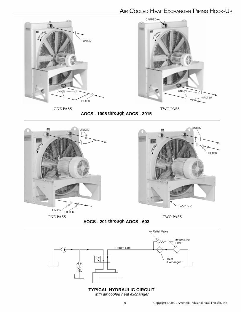
Copyright © 2001 American Industrial Heat Transfer, Inc.
UNION
FILTERUNION
Fan
rota
tion
UNION
FILTER
CAPPED
Fan
rota
tion
AIR COOLED HEAT EXCHANGER PIPING HOOK-UP
AOCS - 1005 through AOCS - 3015
AOCS - 201 through AOCS - 603
ONE PASS TWO PASS
ONE PASS TWO PASS
UNION
CAPPED
FILTER
Fan
ro
tation
UNION
FILTER
UNIONFan
ro
tation
Return Line
Relief Valve
Return LineFilter
HeatExchanger
TYPICAL HYDRAULIC CIRCUITwith air cooled heat exchanger
9

Copyright © 2001 American Industrial Heat Transfer, Inc.
AIR COOLED HEAT EXCHANGERS PIPING HOOK-UP
AC, ACF & AOCH Series
ONE PASS TWO PASS
ACA Series
EOC Series
ONE PASS TWO PASS
ONE PASS
Fan
ro
tation
TWO PASS
Fan
ro
tationINLET
OUTLET
Fan
rotation
Fan
rotation
INLET
OUTLET
INLET
Fan
rotation
Fan
rotation
INLET
OUTLET
Fan
rotation
OUTLET OUTLET
INLET
INLET CAPPED
Fan
rotation
OUTLET
10
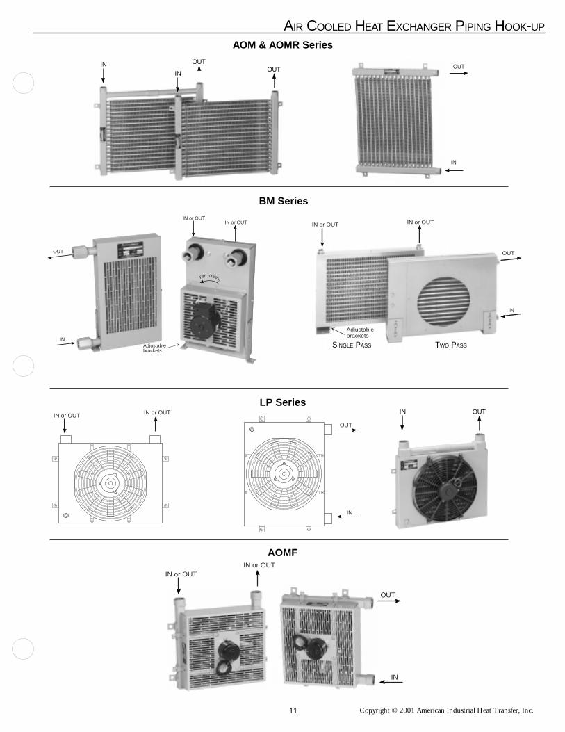
Copyright © 2001 American Industrial Heat Transfer, Inc.
LP Series
OUT
IN
IN or OUT IN or OUT
AOMF
BM Series
Adjustablebrackets
OUT
IN
IN or OUTIN or OUT
Fan rotation
IN or OUTIN or OUT
OUT
IN
AOM & AOMR Series
TWO PASSSINGLE PASS
Adjustablebrackets
OUT
IN
IN or OUT IN or OUT
AIR COOLED HEAT EXCHANGER PIPING HOOK-UP
OUT
IN
IN OUT
IN IN OUT
OUT
11

Copyright © 2001 American Industrial Heat Transfer, Inc.
Insulation of boileror storage tank
Capillarytubing
Tube Clip &rubber gromet
1/2"-14 external threads on spud
Wall or boiler orstorage tank
ImmersionWall
Sensing Bulb
Spud screws into tapping (reducer fitting may be
necessary to adapt spudto tapping)
Sensing Bulb
Composition Disc(slotted)
Packing Nut
Screws into tappingin boiler or tank
Slotted brass washersassembled in pairs
1/2" Capillarycompression fitting
1/2"-14 Externalthreads on spud
CapillaryTubing
ELECTRICAL TEMPERATURE CONTROLLER WITH BULB WELL ASSEMBLY (for Air/Oil Coolers)SPECIFICATIONS:A) Material: Copper
B) Power Limits:
1)For three phase motor operation, use only with a magnetic starter, 125 VA max. (VA =volts x amps)2)For pilot duty, 125 VA max.3)For direct connection to motor:
120v AC/8.0 amps max 230v AC/5.1 amps max277v AC/4.2 amps max 460v AC/2.0 amps max
4)Temperature operating range: 55°F to 175°F.
APPLICATIONS (Temperature Controller)The TC511 temperature controllers are designed to control the tempera-
ture of air or liquids in ducts, pipes, tanks, and boilers. Typical uses includecontrol of dampers and valves in heating, cooling, or heating-cooling sys-tems. The TC511 has 1 spdt switch. It makes or breaks a circuit on a changein temperature at the sensing bulb. Fast response models with adjustabledifferential are available for duct installation. They respond approximately 4times faster than standard models.
INSTALLATIONWhen installing this product:1. Read instructions carefully. Failure to follow the instructions could
damage the product or cause a hazardous condition.2. Check the ratings given in the instructions and on the product to make
sure the product is suitable for your application.3. Installer must be a trained, experienced service technician.4. After installation is complete, check out product operation as provided
in the instructions.
LOCATION AND MOUNTING.The controller may be installed in any convenient position. Mount it
with 3 screws through the slotted holes in the back of the case. Be sure toconsider the length of the capillary before mounting the controller.
Install the sensing element where it is exposed to the average tempera-ture of the controlled medium. The sensing bulb may be directly im-mersed or mounted in a well. Fast response models must use the capillaryholder furnished with the device. The remote sensing bulb of standardmodels should be held in place with a capillary holder, immersion well, orcompression fitting. Sharp bends or kinks in the capillary tubing affect theefficiency of the controller and must be avoided. Excess capillary shouldbe carefully coiled and left directly beneath the controller.NOTE: When pressure fittings are used in areas of vibration (suchas pipe lines) the bulb must be adequately supported.
OPERATIONAs the temperature of the controlled medium falls belowthe set point less differential, the TC511 switch makesterminal R to B and energizes a normally closesolenoid valve to provide heat. In cooling applica-tions, the TC511 makes terminal R to W asthe temperature rises above the set point,energizing cooling equipment.
0.20
2.13
2.25
2.44
2.63
1.220.38
0.94
ø0.88 Knockout Both ends
2.00
ø0.22 (3x)ø0.37 (3x)
4.19
0.69
5.63
1.75
1.94
ELECTRICAL RATINGS:TC511 models with adjustable differential:TC511 models with fixed differential -125 VA at 120/208/240/277 Vac.MAXIMUM BULB PRESSURE: 50 psi (344.7 kPa) for directimmersions.
AIR COOLED ACCESSORIES
12

Copyright © 2001 American Industrial Heat Transfer, Inc.
STANDARD TERMS AND CONDITIONS OF SALE (1/3)
All sales by American Industrial Heat Transfer Inc. ("Seller") to the party to whom aSeller's Acknowledgment is addressed ("Purchaser") are subject to the following termsand conditions in addition to the terms and conditions contained in anyacknowledgement or sales order confirming your order (“Seller’s Acknowledgement”).Where terms of any such Seller’s Acknowledgement conflict with the following termsand conditions, the terms and conditions of Seller’s Acknowledgement shall control.These Terms and Conditions shall apply to all transactions between Seller andPurchaser unless superseded by new Terms and Conditions delivered by Seller or bythe express terms and conditions contained in Seller's Acknowledgment.
Acceptance. All purchase orders are accepted by Seller at its General Offices in Zion,Illinois. Seller's acceptance of any purchase order it receives is expressly limited to theexact terms contained here and in this Seller's Acknowledgment. Additional ordifferent terms contained in Purchaser's offer or any attempt by Purchaser to vary anyof the terms here and in Seller's Acknowledgment shall be rejected but such proposalshall not operate as a rejection of Purchaser's offer unless such variances are in theterms of the description, quantity, price or delivery schedule of the goods or services tobe provided hereunder, in which case such additional or different terms shall bedeemed material and such offer shall be deemed accepted without said additional ordifferent terms or attempted variations. Acceptance by Seller of any purchase ordercontaining terms additional to or different from the terms contained in this Seller'sAcknowledgment or containing modifications of the terms contained here and inSeller’s Acknowledgment shall not be deemed as assent to those additional, different ormodified terms. Purchaser's receipt of Seller's Acknowledgment without promptwritten objection thereto, or Purchaser's acceptance of all or any part of the goods orservices ordered from Seller, shall constitute assent by Purchaser to the termscontained here and in Seller's Acknowledgment. If this Seller's Acknowledgment shallbe deemed an offer by Seller to sell goods or services to Purchaser, such offer isexpressly limited to the exact terms contained herein. The dispatch of a purchase orderby Purchaser shall then constitute Purchaser's acceptance of these Standard Terms andConditions of Sale and Seller's Acknowledgment. If this Seller's Acknowledgment isdeemed an offer as aforesaid, any proposal by Purchaser for additional or differentterms or any attempt by Purchaser to vary any of the terms of this Seller's Acknowledg-ment in Purchaser's purchase order is hereby objected to and rejected; provided,however, that any such proposal by Purchaser shall not operate as a rejection of Seller'soffer unless it contains variances in the terms of the description, quantity, price ordelivery of the goods or services to be provided hereunder, in which case any suchproposal shall be deemed material, and this Seller's Acknowledgment shall be deemedaccepted without said additional or different terms or attempted variations.
Payment Terms. The full amount billed or contracted for is due and payable thirty (30)days from delivery of the goods or performance of services. A finance chargecomputed at the periodic rate of one and one-half percent (1.5%) per month (which isan annual rate of eighteen percent (18%)) on the unpaid balance will be made onaccounts not paid when due, and Purchaser agrees to pay such charges and payattorneys' fees if action is brought to collect from Purchaser. Unless otherwisespecified, 100% of the price quoted for any tooling is to be paid with the placement ofthe order to Seller. Samples submitted shall be deemed approved and accepted ifwritten notice of rejection is not received within thirty (30) days after date ofsubmittal. Purchaser agrees that Seller shall have a possessory lien on all tools andother property of Purchaser which is in Seller's possession for the total amount owingby Purchaser to Seller for all tooling and other work and for all parts, materials andservices of all kinds supplied or rendered by Seller to Purchaser, which lien shall beenforceable in the manner provided in the Uniform Commercial Code.
Taxes. Any tax which the Seller may be required to pay or collect through assessmentor otherwise, under any existing or future law upon or with respect to the sale,purchase, delivery, transportation, storage, processing, use or consumption of anygoods or services described herein, including, without limitation, taxes upon ormeasured by receipt from sales or services (but excluding taxes based upon the incomeof Seller), shall be for the account of Purchaser and be added to the price of such goodsor services. Purchaser shall promptly pay the amount thereof to Seller upon demandbut may in lieu of such payment, furnish to Seller evidence of the issuance of taxexemption certificates acceptable to the appropriate taxing authorities.
Prices. Except as otherwise provided, all price quotations are valid for thirty (30) days.Prices are based on costs prevailing on the date of quotation and, therefore, are subjectto change at any time to reflect increased costs. Prices are quoted on samples,blueprints, or drawings on hand, and any modification thereof subjects this quotation toadjustment. Quotations are is based on the continuous production of the quantityspecified, smaller runs subject to increase in price. If higher quantity level is desiredby Purchaser, Seller will render a quotation based upon the revised requirements setforth by Purchaser.
Credit. All orders are subject to the approval of Seller's Credit Department, and Sellermay at any time refuse to make shipment or delivery if Purchaser fails to fulfill theterms and conditions of payment or fails to provide security satisfactory to Seller'sCredit Department. Seller reserves right to refuse or cancel credit and require fullpayment prior to shipment. If in Seller's opinion the financial condition of Purchaserat any time does not justify continuation of production or shipment on the terms ofpayment specified, Seller may require full or partial payment in advance or suchfurther assurance as Seller shall require to justify such continued production orshipment.
Default in Payment and Bankruptcy of Purchaser. If Purchaser fails to make paymentson any agreement between Purchaser and Seller in accordance with Seller's terms,Seller, in addition to any other remedies available to it, may, at its option, (a) deferfurther shipments until such payments are made and satisfactory credit arrangementsare reestablished, (b) cancel the unshipped balance of any order or (c) take any otheraction available under applicable law. In the event of any proceedings, voluntary orinvoluntary, in bankruptcy or insolvency by or against Purchaser, the inability ofPurchaser to pay its debts as they become due, or in the event of the appointment, withor without Purchaser's consent, of an assignee for the benefit of creditors or of areceiver, then Seller shall be entitled, in its sole discretion, to cancel the unshippedbalance of any order without any liability.
Transportation Charges. All prices, quotations, shipments and deliveries by Seller areF.O.B. Seller's plant and risk of loss passes to Purchaser once goods are tendered forsuch delivery. All transportation and other charges including handling fees are for theaccount of Purchaser, including any increase or decrease in such charges prior toshipment.
Method of Shipment. Method and route of shipment is at Seller's discretion, unlessPurchaser supplies explicit instructions, which are subsequently accepted by Seller inwriting. Seller does not assume responsibility for any damage directly or indirectlyresulting from delays in delivery. When parts are broken or damaged in transit fromSeller to Purchaser, it is considered the responsibility of Purchaser to file a claim withthe carrier for said breakage or damage. If the method of shipment specified byPurchaser is deemed by Seller to be unavailable or otherwise unsatisfactory, Sellerreserves right to use an alternate method or route or both whether or not at a highercost to Purchaser. Seller shall promptly notify Purchaser of any such change. The riskof loss or damage to the goods shipped shall pass to the Purchaser when the goods aredelivered to the carrier for shipment and Purchaser shall be responsible for insuringsuch goods thereafter.
Producing or Shipping Point. Seller reserves right to produce and ship all or any partof the goods specified in any order from any of its plants or facilities.
Force Majeure. Seller shall not be liable for any delay in the performance of orders, orin the delivery or shipment of goods, or for any damages suffered by Purchaser as aresult of such delay when such delay is occasioned by causes beyond Seller's control.Such causes shall include but are not limited to an act of God or the public enemy, fire,explosion, flood, unusually severe weather, drought, war, riots, sabotage, vandalism,accident, embargo, government priority, government action or failure of the govern-ment to act when action is required, requisition or allocation or other action of anygovernmental authority, interruption of or delay in transportation, inadequacy orshortage or failure of supply of materials or equipment, breakdowns, non-scheduledshutdowns for repairs, plant accidents, labor shortage, strikes, labor trouble, or bycompliance with any order or request of the United States Government or any officer,department, agency, instrumentality or committee thereof. It is understood and agreedthat economic conditions affecting the ability or desirability of the performance of thisagreement by either party shall not be deemed to constitute "force majeure" circum-stances as contemplated by this paragraph. The Seller shall have the right to cancel theentire agreement with Purchaser or any part thereof in the event of the happening ofany such cause beyond the Seller's control without any resulting liability.
Good Delivery. Shipments made by Seller within a reasonable time after the specifieddate of delivery shall constitute a good delivery. No right of cancellation shall accrueto Purchaser based on such a delivery.
Permissible Variations. Goods shipped by Seller shall be within the limits and sizespublished by Seller, subject, however, to Seller's right to ship overages or underages inaccordance with Seller's standard practices and goods shipped by Seller will be subjectto standard variations provided such variations are non-functional or are not material innature.
LIMITED WARRANTY. SELLER MAKES NO WARRANTIES EXPRESSED OR
STANDARD TERMS AND CONDITIONS OF SALEApril 1, 2000 Supersedes all prior "Standard Terms And Conditions Of Sale"
13

Copyright © 2001 American Industrial Heat Transfer, Inc.
STANDARD TERMS AND CONDITIONS OF SALE (2/3)IMPLIED, INCLUDING BUT NOT BY WAY OF LIMITATION, ANY IMPLIEDWARRANTY OF MERCHANTABILITY AND ANY IMPLIED WARRANTY OFFITNESS FOR A PARTICULAR PURPOSE, ON ANY ORDER EXCEPT THATSELLER WARRANTS TITLE TO ALL GOODS FURNISHED BY SELLER ANDEXCEPT THAT SELLER WARRANTS FOR A PERIOD OF ONE YEAR FROM THEDATE MARK LOCATED ON THE SELLER'S IDENTIFICATION TAG THAT ALLGOODS DESCRIBED ON SELLER'S ACKNOWLEDGMENT OF PURCHASER'SPURCHASE ORDER WILL BE MANUFACTURED IN ACCORDANCE WITH THESPECIFICATIONS, IF ANY, SET FORTH IN SAID PURCHASE ORDER ANDEXPRESSLY ACCEPTED IN SELLER'S ACKNOWLEDGMENT SUBJECT TOSELLER'S STANDARD MANUFACTURING VARIATIONS AND PRACTICES. INTHE CASE OF COMPONENTS OR ACCESSORIES FURNISHED BY SUPPLIERSTO SELLER, PURCHASER'S WARRANTY FROM SELLER SHALL BE LIMITEDTO THE WARRANTY OF THE COMPONENT OR ACCESSORY SUPPLIER. THEFOREGOING WARRANTIES ARE THE SOLE AND EXCLUSIVE WARRANTIESAPPLICABLE TO THE GOODS DELIVERED, AND ALL OTHER WARRANTIES,EXPRESS OR IMPLIED, INCLUDING WITHOUT LIMITATION ANY WAR-RANTY OF MERCHANTABILITY, ARE HEREBY EXPRESSLY DISCLAIMEDAND NEGATED. WITHOUT LIMITING THE GENERALITY OF THE FOREGO-ING, PURCHASER ACKNOWLEDGES THAT SELLER'S PRODUCTS ARE NOTPACKAGED OR PROTECTED FOR LONG PERIODS OF STORAGE AND THUSMAY CORRODE OR RUST OVER TIME.
Damaged Goods. If any goods should arrive at Purchaser's destination in a damagedcondition or should a shortage occur, Purchaser shall immediately report the damage orshortage to the delivering carrier and to Seller. Any loss or shortage occasioned bydamage or otherwise occurring in transit will be for account of Purchaser. Allegedlydefective goods or parts are to be returned by Purchaser to a destination specified bySeller, freight charges prepaid by Purchaser. All repairs and replacements are subjectto verification and inspection by Seller. Seller shall not be responsible for costs of de-installation and re-installation of goods or parts returned.
Claims. Claims respecting the condition of goods, compliance with specifications orany other matter affecting goods shipped to Purchaser must be made promptly and,unless otherwise agreed to in writing by Seller, in no event later than twenty-one (21)days after receipt of the goods by Purchaser. Purchaser shall set aside, protect andhold such goods without further processing until Seller has an opportunity to inspectand advise of the disposition, if any, to be made of such goods. In no event shall anygoods be returned, reworked or scrapped by Purchaser without the express writtenauthorization of Seller. If field service is rendered by the Seller at Purchaser's requestand the alleged defect is found not to be with the Seller's product, component oraccessory, the Purchaser shall pay for the time and expenses of the field representative.Bills for service, labor or other expenses that have been incurred by the Purchaser,their customer or agent, without approval or authorization by the Seller, will not beaccepted. Changes or repairs attempted or made in the field without Seller's writtenauthorization automatically void all warranties.
LIMIT ATION OF PURCHASER'S REMEDIES. PURCHASER'S REMEDIES WITHRESPECT TO ANY CLAIM ARISING OUT OF ANY ORDER, ANY GOODSDELIVERED PURSUANT TO ANY ORDER AND EXPRESSLY ACCEPTED INSELLER'S ACKNOWLEDGMENT, OR SELLER'S PERFORMANCE IN CONNEC-TION WITH ANY ORDER, INCLUDING, WITHOUT LIMITATION, ANY CLAIMARISING OUT OF ANY RECALL, DEFECT OR ALLEGED DEFECT IN ANYGOODS OR SERVICES FURNISHED BY SELLER, SHALL BE LIMITEDEXCLUSIVELY TO THE RIGHT OF REPAIR OR REPLACEMENT OF SUCHGOODS OR SERVICES, AT SELLER'S OPTION. WITHOUT IN ANY WAYLIMITING THE GENERALITY OF THE FOREGOING, IN NO EVENT SHALLSELLER BE LIABLE FOR ANY CONSEQUENTIAL OR INCIDENTAL DAM-AGES, INCLUDING, WITHOUT LIMITATION, ANY LOSS OF ANTICIPATEDPROFITS INCURRED BY PURCHASER WITH RESPECT TO ANY GOODS ORSERVICES FURNISHED BY SELLER, OR ANY DAMAGES ARISING FROMINJURIES TO PERSONS AS A RESULT OF PURCHASER'S OR A THIRD PARTY'SNEGLIGENCE. SELLER'S WARRANTY DOES NOT COVER FAILURESRESULTING FROM THE IMPROPER INSTALLATION, MOUNTING DESIGN ORAPPLICATION OR FROM CORROSION. THE PROVISIONS OF THIS PARA-GRAPH ARE A MATERIAL TERM OF THIS TRANSACTION.
Warranty Procedures. If Purchaser experiences a problem with Sellers goods andbelieves that it is covered by Seller's warranty, or Purchaser has equipment that needsto be repaired or replaced, contact Seller through Purchaser's local distributor. Thebasic information that Purchaser will need to begin the process is the completenameplate data. Products will not be accepted for return unless an RGA (Return GoodsAuthorization) number has been assigned by Seller and the product for return or repairis shipped prepaid. Products returned for warranty evaluation must be complete(without missing components), and unaltered (not disassembled, manipulated cleanedor the like). The product(s) must have the original model tag fully intact. Productsreturned for warranty consideration are subject to a $100 minimum fee plus any
additional handling charges in the event that the reason for the return is not covered bySeller's warranty. Additional handling fees are to cover the cost of failure analysis,testing and the like. All handling charges will be waived for products that are subjectto a valid warranty claim. Products to be returned for warranty are to be shippedprepaid via Seller assigned carrier.
Returns and Returns Procedures. In order to return a product for credit, test, or repair,Purchaser must follow the procedures outlined in this paragraph and, in the case ofrepairs, the immediately following paragraph. Failure to follow return procedurescould result in lost items, delays, additional service charges, warranty denial or refusalof shipment. All items being returned to Seller must be accompanied with an RGA(Return Goods Authorization) number for identification purposes. Products returnedwithout a clearly marked RGA number will not be processed. RGA numbers can beobtained only through Seller. Products being returned for restock and credit must becomplete (without missing components), unused, and within one year of originalfactory purchase. The products must have the original model tag fully intact. Returnedproducts must be free of dents, customer applied paint, rust, or any permanentalterations of any type. Products shipped for restock are to be shipped prepaid. Heatexchangers being returned for credit are subject to a 30% restocking charge. Otheritems such as, without limitation, valves and temperature controls are subject to a 15%-50% restocking charge to be determined by the products’ usage or salability.Restocking charges are applied to cover the cost or the retest and refitting equipment tonew condition. Seller will issue credit only after a thorough inspection has beenperformed. NO DEBITS WILL BE HONORED UNTIL AFTER RETURN INSPEC-TION APPROVAL.
Repairs. Products being returned for repair, refit, test or similar matters must bedrained completely prior to shipment. Purchaser must clearly label the product withinformation to identify the Purchaser and Seller's RGA number. Purchaser should alsoinclude a note with instructions for service, failure, nature of problem and the fluidsthat are used inside of the product. A base handling charge of $100 will be applied foreach product regardless of condition that it is in when returned for evaluation.Products being returned for evaluation must be shipped prepaid. Quotations for repair,test, cleaning, and similar matters will be issued shortly after return to Seller. Allproducts returned shall be considered abandoned by Purchaser and may be scrapped ifthe Purchaser or shipper renders no disposition instructions after 45 days fromnotification by written quotation. Seller does not warranty any repaired products underany circumstances. Products repaired and the repairs are the sole responsibility of theowner of the products. Products sent to Seller for evaluation will be returned, uponrequest and at the owner’s expense.
Quality Assurance. Seller shall have no obligation to ensure that any goods or servicespurchased from Seller meet any special quality assurance specifications and/or otherrequirements unless such specifications and/or other requirements are set forth inPurchaser's purchase order or separately provided in writing to Seller and, in eithercase, expressly accepted in this Seller's Acknowledgment and Purchaser represents thatgoods which it purchases from Seller will not be applied by Purchaser or resold byPurchaser for application to, any critical end use, including, without limitation, use inconnection with or in any way related to the construction or operation of a nuclearfacility unless the appropriate specification and/or other requirement for such end useis set forth in Purchaser's purchase order and is expressly accepted in a separate writingby Seller. In the event that any such goods or any services supplied by Seller inconnection therewith are applied to a critical end use without the appropriatespecification and/or other requirement therefor having been set forth in Purchaser'spurchase order and expressly accepted in a separate writing by Seller, Purchaser shallindemnify and hold Seller harmless against any and all damages or claims for damagesmade by any person for any injury, fatal or nonfatal, to any person or for any damageto the property of any person incident to or arising out of such application, including,without limitation, any loss resulting from radioactive, toxic, explosive, or otherhazardous properties of source material, special nuclear material, or by-productmaterial as such terms are defined in the Atomic Energy Act of 1954 or any lawamendatory thereof or regulations adopted pursuant thereto. The Seller reserves theright to improve its products through changes in design or material, as it may deemdesirable without being obligated to incorporate such changes in products of priormanufacture.
Cancellation. Purchaser Orders cannot be cancelled without cause by Purchaserwithout the express written consent of the Seller. Should Purchaser attempt to cancelan order without cause, Purchaser shall reimburse Seller against all loss occasioned bysuch cancellation, including loss of anticipatory profits and liability for commitmentsmade by Seller relating to the Purchase Order and shall purchase any existinginventory and work in process which Seller has in its possession to fulfill Seller'sexisting orders for Purchaser at the time of cancellation. As used herein, "cause" shallmean a material breach of Seller's duties and obligations hereunder and the failure tocure such breach after Purchaser notifies Seller of such breach and affords Seller areasonable time to cure same.
14

Copyright © 2001 American Industrial Heat Transfer, Inc.
Confidentiality and Publicity. Purchaser shall consider all information furnished bySeller to be confidential and shall not disclose any such information to any person, firmor corporation, other than Purchaser's or Seller's employees, subcontractors orgovernment inspectors, unless authorized to do so by Seller in writing. Purchaser shallnot disclose in any manner to third parties, including, without limitation to, advertis-ing, or publishing concerns, Seller's identity or the identity of any subsidiaries oraffiliates of Seller. Unless otherwise agreed to in writing, no commercial, financial ortechnical information disclosed in any manner or at any time by Purchaser to Sellershall be deemed secret or confidential and Purchaser shall have no rights against Sellerwith respect thereto except such rights as may exist under patent laws.
Tooling. If and to the extent any Purchase Order relates to the purchase of tools, jigs,die fixtures, equipment, drawings and specifications (collectively, "tooling") orspecifically requires tooling for completion by Seller, then Seller shall at all times beand remain the owner of such tooling and shall bear the risk of loss and be responsiblefor insuring same. If any Purchase Order requires the development of such tooling,then the price quoted by Seller is based on a minimum production of a specifiedquantity of parts from such tooling and, in the event Purchaser does not ultimatelypurchase such quantity of parts, an equitable adjustment in the purchase price forproducts shall be made to reflect such lower quantity and Seller's unamortized cost ofthe tooling so produced. Seller's price quotation is based upon estimated usage oftooling but no representations or warranties are made by Seller that the tooling so builtwill ultimately be capable of producing product in accordance with such anticipatedusage. Purchaser agrees to pay for changes in tooling made necessary by changes inspecifications accepted by Seller, such changes to be made at Purchaser's risk. Partsproduced from Purchaser's supplied tooling cannot be guarantied by Seller. Purchaserprovided tooling is not insured and Seller shall not be responsible or liable for any lossor damage thereto or for any materials or equipment owned or furnished by Purchaser.Purchaser shall be solely responsible for insuring such tooling and Purchaser waivesany claim or right of subrogation it may have against Seller arising out of Seller'sfailure to insure such tooling. Seller reserves the right to charge Purchaser thereasonable costs and expenses of refurbishing any tooling if so required by Seller tofulfill any Purchase Order. When for a period of one (1) year no orders are receivedfor parts to be produced from tooling, Seller may notify Purchaser in writing atPurchaser's last known address in Seller's files that tooling is no longer proprietary toPurchaser and, with respect to Purchaser supplied tooling, such tooling shall becomeSeller’s property or, at Seller’s option, Seller man return such tooling to Purchaser atPurchaser’s expense.
Prototypes. If this Purchase Order relates to the production of a prototype by Seller foror on behalf of Purchaser, (a) such prototypes will be manufactured in accordance withPurchaser's specifications including material selection and (b) actual product producedby Seller may vary from such prototype in a non-material and non-functional manner.Seller's sole liability in the event it is unsuccessful in producing a prototype inaccordance with Purchaser's specifications shall be limited to the purchase price paidby Purchaser with respect thereto. Purchaser shall be responsible for the cost of alltooling necessary for the development of the prototype as provided in the paragraphCaptioned “Tooling” above.
Technical Assistance and Advice. Seller's warranty shall not be enlarged and noobligation or liability shall arise out of Seller's rendering of technical assistance,technical advice facilities, service or recommendations made by Seller in connectionwith Purchaser's purchases of the goods hereunder. Said technical services, advice,assistance or recommendations made by Seller or any representative of Sellerconcerning any use or application of any goods furnished hereunder is believed to bereliable, but SELLER MAKES NO WARRANTY, EXPRESS OR IMPLIED, ANDTHE SAME ARE HEREBY EXPRESSLY DISCLAIMED as to the same and theresults to be obtained. Purchaser assumes all responsibility for loss or damageresulting from the use of any such goods.
Indemnification. Purchaser agrees to indemnify, save harmless and defend Seller fromand against any and all liability for loss, damage or injury to person or property in anymanner arising out of or incident to the performance of any Seller's Acknowledgmentor other sale by Seller or its servants, employees, agents or representatives. Withoutlimiting the generality of the foregoing, Purchaser will indemnify and hold harmlessSeller, its officers, employees, agents, successors, assigns, customers and users of itsproducts from and against any and all losses, expenses, claims, suits and liabilities(including incidental and consequential damages and court costs and attorneys fees)arising as a result of any claim that the manufacture, use, sale or resale of goodsdelivered by Seller in accordance with Purchaser's specifications or designs infringeson any patent, utility model, industry design, copyright or other intellectual propertyrights in any country. Without limiting the generality of the paragraph captioned“LIMITATION OF PURCHASER’S REMEDIES” above, in the case of any claim ofinfringement or the sale of products is enjoined, Seller shall have no obligation toprocure for Purchaser the right to continue using such products or to replace same withequivalent non-infringing products or to modify the products so they become non-
STANDARD TERMS AND CONDITIONS OF SALE (3/3)infringing.
Setoffs. Purchaser shall make no deduction or setoff for any claim arising out of or fromany transaction with Seller nor shall Purchaser take any discount, credit or allowancewithout Seller's written consent.
Assignment. Purchaser shall not assign any order or any interest therein without the writtenconsent of Seller. Any such actual or attempted assignment without Seller's prior writtenconsent shall entitle Seller to cancel such order upon written notice to Purchaser.
Termination. Seller may terminate any order or any part thereof for any reason at Seller'sconvenience upon written notice to Purchaser. Upon such termination, Purchaser agrees towaive all claims for damages including, without limitation, any loss of anticipated profits,and to accept as its sole remedy for termination the reasonable additional costs of obtainingsubstitute goods of the same quantity and quality, provided that in no event shall such costsexceed the price of the order or part thereof so terminated as stated on Seller's Acknowledg-ment. Any claim for adjustment not asserted within sixty (60) days from the date of suchtermination shall be deemed to have been waived by Purchaser.
Allocation of Risk. Purchaser acknowledges that these Standard Terms and Conditions ofSale and Seller's Acknowledgment allocates risks with respect to goods and/or services soldto Purchaser and this risk allocation is reflected in the prices to be paid by Purchaser forsaid goods and/or services purchased hereunder. Purchaser warrants that it has read thisprovision, understands it and is bound by its terms.
Packaging. Seller will use all reasonable means to comply with any packaging, loading orbracing requirements specified in any order. Seller will charge for compliance withPurchaser's special requirements in accordance with Seller's price list for extras in effect attime of shipment. If no packaging, loading or bracing requirements are specified byPurchaser, Seller shall comply with the minimum requirements customarily applied bySeller to the method of transportation used for such goods.
Entire Agreement. These Standard Terms and Conditions of Sale and Seller’s Acknowledg-ment and any other documents referred to on the face thereof constitute the entireagreement between Seller and Purchaser.
Modification. No addition or modification of the terms and conditions of these StandardTerms and Conditions of Sale and Seller’s Acknowledgment shall be binding on Sellerunless specifically agreed to by Seller in writing.
Waiver. Seller's failure to insist on performance of any of these Standard Terms andConditions of Sale and Seller's Acknowledgment or to exercise any right or privilege orSeller's waiver of any breach hereunder shall not thereafter waive any other terms,conditions, or privileges, whether of the same or similar type.
Governing Law. Seller and Purchaser's agreement shall be governed by and interpreted inaccordance with the laws of the State of Illinois of the United States of America.Manufacture, shipment and delivery are subject to any prohibition, restriction, priority,allocation, regulation or condition imposed by or on behalf of the United States of Americaor any other governmental body with appropriate jurisdiction which may prevent orinterfere with fulfillment of any order.
Re-orders. Re-orders, if accepted by Seller, are considered as placed under the same termsand conditions as Purchaser's previous order, when such orders are not placed pursuant to aformal written proposal and acceptance.
Disclosure. Seller shall have the right to disclosure of the identity of Purchaser and thenature of the work Seller is performing on Purchaser's behalf to Seller's customers andprospective customers and in any promotional materials provided such disclosure does notcontain any confidential and proprietary information concerning Purchaser.
DISPUTES. SELLER AND PURCHASER AGREE TO SUBMIT ANY DISPUTESREGARDING ANY ORDER, ANY GOODS DELIVERED PURSUANT TO ANY ORDERAND EXPRESSLY ACCEPTED IN SELLER'S ACKNOWLEDGMENT, OR SELLER'SPERFORMANCE IN CONNECTION WITH ANY ORDER, INCLUDING WITHOUTLIMITATION SELLER'S LIMITED WARRANTY OBLIGATION, TO MEDIATION BYAN INDEPENDENT MEDIATOR TO BE MUTUALLY AGREED UPON BY SELLERAND PURCHASER. THE COST OF SUCH MEDIATION SHALL BE BORNEEQUALLY BY SELLER AND PURCHASER. IN THE EVENT SUCH MEDIATIONDOES NOT RESOLVE THEIR DISPUTE, SELLER AND PURCHASER AGREE TOSUBMIT SUCH DISPUTE TO AN INDEPENDENT ARBITRATOR, TO BE MUTUALLYAGREED UPON BY SELLER AND PURCHASER OR, OTHERWISE, CHOSEN BY THEMEDIATOR. SELLER AND PURCHASER AGREE THAT ALL MEDIATION ANDARBITRATION SHALL BE CONDUCTED IN ZION, ILLINOIS. THE NON-PREVAIL-ING PARTY AT THE ARBITRATION SHALL PAY THE PREVAILING PARTY'SATTORNEYS' FEES AND COSTS INCURRED IN PARTICIPATING IN THE ARBITRA-TION.
15

Copyright © 2001 American Industrial Heat Transfer, Inc.
AOCH Series with screen & Serviceable Core®
• Industrial high capacity air/oil heat exchanger available in 8standard sizes with electric or hydraulic drive.
AC,ACHM & ACF Series • Industrial air/oil heat exchanger available in 8 standard sizes with
electric or hydraulic drive.
ACA Series• Heavy-duty Serviceable Core® air cooled air after-coolers for
compressor sizes up to 500 HP.
AVAILABLE PRODUCTS
URCS Series • U-tube heat exchangers for steam services with removable tubesbundle in copper, 316L SS, or 90/10 Cu Ni.
CS Series• Heat exchangers in copper, 316L SS, or 90/10 Cu Ni.
EOC Series with electric motor & filter as an option.
• Versatile industrial/mobile grade heat exchanger available withoptional filter, AC, DC, and hydraulic drives.
American Industrial Heat Transfer, Inc. 3905 Route 173 - Zion, IL 60099 Tel: (847) 731-1000
16