og11136 autocad plant 3d specs and catalogs: how to …
TRANSCRIPT

OG11136
AutoCAD Plant 3D Specs and Catalogs: How to Create “Unbreakable” Project Workflows Joel Harris Autodesk, Inc.
Learning Objectives Discover how spec items are linked to their source catalog
Discover how AutoCAD Plant 3D model components are linked to their spec items
Learn how to incorporate spec changes into 3D models during the course of a plant design project
Learn workflows for updating piping specs while maintaining relationships with catalogs and 3D models
Description This class will cover the benefits of maintaining the connection between your AutoCAD Plant 3D software catalog, spec, and 3D models, and how to implement workflows to ensure your team’s ability to update model components from the specs and catalogs. We will explore in-depth how to establish and maintain a link between the AutoCAD Plant 3D catalog and spec. Also, we will cover how AutoCAD Plant 3D software establishes a link between the model and spec components and proper workflows for keeping this connection viable during the various types of changes typical to a plant design project. We will also explore the behavior of the PLANTSPECUPDATECHECK command and how you can use it to keep your models up to date with spec and catalog modifications.
Your AU Expert
After studying Mechanical Engineering at Caltech, Joel Harris worked for an AutoCAD third-party developer named Synthesis and also began teaching AutoCAD classes at Bellingham Technical College. From there he started a 23-year career as a piping designer and Plant software developer/administrator for an engineering company in Bellingham, WA. He's the author of Autodesk’s “Introduction to Piping Design with Plant 3D” college curriculum and is part of the Autodesk Enterprise Priority Support team of specialists.

Contents
Learning Objectives ............................................................................................................................. 1
Description .......................................................................................................................................... 1
Why Spec Changes Happen to Good People ..................................................................................... 3
A Glimpse behind the Curtain .......................................................................................................... 3
Examining the Spec-Catalog Connection .............................................................................................. 4
How does a spec know where to find the catalogs that were used while creating it? ....................... 4
Where do I look in the spec for my components and their GUIDs? ................................................... 8
Updating the Spec Parts with Catalog Updates................................................................................. 9
Examining the Model-Spec Connection .............................................................................................. 13
Where do I look in the spec and project database for my components and their IDs? .................... 13
Updating the Model with Spec Changes ............................................................................................. 15
Controlling How and When AutoCAD Plant 3D Checks for Spec Updates ........................................ 15
Maintaining Connections and Incorporating Catalog/Spec Changes in Models during a Project ......... 19
Workflow Example: Updating Catalog Parts ................................................................................... 20
Workflow Example: Adding Catalog Parts to Specs/Modifying Specs .............................................. 22
Workflow Example: Renaming a Spec ............................................................................................ 25
Summary ........................................................................................................................................... 27
OG11136 - AutoCAD Plant 3D Specs and Catalogs: How to Create “Unbreakable” Project Workflows
3
AutoCAD Plant 3D Specs and Catalogs: How to Create “Unbreakable” Project Workflows
Why Spec Changes Happen to Good People One of the most predictable (and frustrating) elements of project execution is design changes – whether they are as large as scope of work or as (arguably) small as client preferences – change is inevitable. Most of you don’t need to be reminded of this, but rather are probably taking this class to acquire the knowledge to deal with this phenomena. Although this class can’t help with schedule crunches and poor timing when it comes to piping spec changes, it will help you streamline your workflows as well as understand what is happening behind the scenes in AutoCAD Plant 3D when it comes to specs and catalogs. The techniques shown in this class assume a high level of software expertise and, if misapplied, can render your specs and/or catalogs useless.
A Glimpse behind the Curtain One of the goals of this class is to teach you how AutoCAD Plant 3D creates connections between the catalog and the spec as well as between the spec and the 3D model. Understanding these two connections will be important to being able to implement spec and catalog changes during the course of any piping project. This class will also outline a workflow from start to finish where you can implement changes to a catalog and have that propagate through to the spec and subsequently to the 3D model. These changes will then be reflected in the project deliverables: isometrics, orthographic drawings and material takeoffs.
The way AutoCAD Plant 3D keeps track of these connections is through the use of unique ID numbers. One type of unique ID number that is used to maintain connections between the spec and the catalog is something called a GUID, or “Globally Unique IDentifier”. This is defined in Wikipedia as:
“A unique reference number used as an identifier in computer software. GUIDs are usually stored as 128-bit values, and are commonly displayed as 32 hexadecimal digits with groups separated by hyphens, such as {21EC2020-3AEA-4069-A2DD-08002B30309D}. The total number of unique such GUIDs is 2122 (approximately 5.3×1036). This number is so large that the probability of the same number being generated randomly twice is negligible.”
Here’s an important fact to remember:
AutoCAD Plant 3D uses the process of adding a component to a catalog, spec or 3D model as a trigger to assign it a new ID. These IDs are used throughout the software to track items and their relationships with each other. They are hidden from the user interface, but are stored within the catalog files, the spec files and the project database files.
Because AutoCAD Plant 3D and P&ID are SQL based, you can use SQL or SQLite tools to view these files and get a peek behind the scenes. During this class we will be using one such tool called “SQLite Expert”
Whenever a new component is added to a catalog, spec or 3D model, it gets assigned a new, unique ID number.
Important Fact #1

OG11136 - AutoCAD Plant 3D Specs and Catalogs: How to Create “Unbreakable” Project Workflows
4
by Coral Creek Software (http://www.sqliteexpert.com). It is strongly recommended that you always keep backup copies of your files before viewing them with tools like this, and never edit a file that is currently in use by AutoCAD Plant 3D or P&ID.
Examining the Spec-Catalog Connection Creating and maintaining catalogs is a common task among AutoCAD Plant 3D administrators. Although the software is delivered with several industry standard component catalogs and specs (as well as making many more available for download on https://apps.autodesk.com), chances are good that you will be creating your own custom catalogs and specs to execute actual project work. Before we explore how to update spec parts to reflect catalog changes, we need to take a look at database records within the specs and catalogs. To accomplish this, let’s answer a couple of questions:
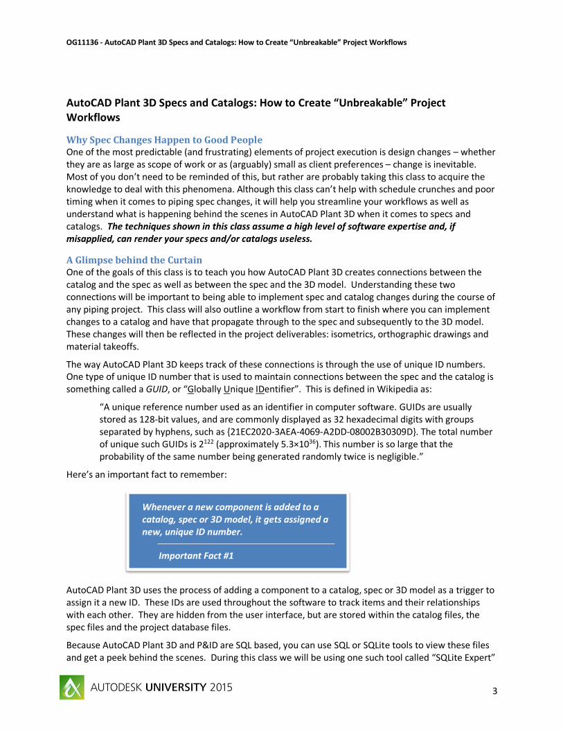
How does a spec know where to find the catalogs that were used while creating it? All AutoCAD Plant 3D piping specs are comprised of two files with the same name but different extensions: <specname>.pspc and <specname>.pspx. The <specname>.pspc file is a SQLite database that contains many tables and views. For those unfamiliar with databases, think of each table as a set of data stored in a grid of rows and columns and each view as a custom grid of data pulled from one or more tables as a result of a database query statement. For the purposes of this class, we will only need to refer to one table (named EngineeringItems) and one view (named EngineeringItems_PNP) in the spec. Either can be viewed in a SQLite viewer to see the data that is used by both AutoCAD Plant 3D and the AutoCAD Plant 3D Spec Editor.
OG11136 - AutoCAD Plant 3D Specs and Catalogs: How to Create “Unbreakable” Project Workflows
5
FIGURE 1: SPEC TABLES AND VIEWS
For each component in the spec there will be one row (called a record) in the table or view. Also, each record has the same number of columns, each column storing a particular type of data. One of these columns is called the CatalogId column and it stores the name of the AutoCAD Plant 3D catalog (minus the .pcat extension) that was the source for this record. In other words, this is the name of the catalog that was used in the Spec Editor with the “Add to Spec” command.

OG11136 - AutoCAD Plant 3D Specs and Catalogs: How to Create “Unbreakable” Project Workflows
6
FIGURE 2: CATALOGID COLUMN IN A SPEC
You probably notice that the path to the catalog is not included as part of the catalog name. This is by design, and leads us to the next question, which is: “Now that I know the name of the catalog, where is it?” It is worth noting that for out-of-the-box, parametric shape-based parts, AutoCAD Plant 3D does not require any information about the catalog, because it has all of the information it needs to create a component in the spec itself. It is only the AutoCAD Plant 3D Spec Editor that needs to know the catalog name and location so that it can load the catalogs automatically when the spec is opened for editing. There are two exceptions to this fact, and it is important to consider these when deciding to implement custom, block-based and Python script-based parts:
1. With block-based parts, when the catalog location has moved and you try to place a block-based part, sometimes it gives the error: “Can’t find symbol for specified part”. This means AutoCAD Plant 3D was unable to locate the DWG file containing the custom blocks in any of the sub-folders of the shared content (catalog) folders. To avoid this, always create a folder under your custom catalog folder to contain the blocks that are used in that catalog. Then, when the catalog is moved, the blocks will be moved along with it. When a block-based part is placed from a spec in AutoCAD Plant 3D, it scans through the catalog and its subfolders until it finds the drawing that contains the block.
2. For script based (python) components, we have this information from Dave Wolfe’s AU 2014 class:
Script Locations - Plant 3D will load custom scripts from a specific location. By default that location is C:\AutoCAD Plant 3D 2016 Content\CPak Common\CustomScripts\. If you do not have this folder, you can create it in the CPak Common folder.
So when it comes the finding the catalog from the list of catalog names in the spec, the software looks in two places and then prompts the user if it still can’t find the catalog:

OG11136 - AutoCAD Plant 3D Specs and Catalogs: How to Create “Unbreakable” Project Workflows
7
1. First, the AutoCAD Plant 3D Spec Editor looks in the <specname>.pspx file. This file is actually a compressed folder (you can change its extension to ZIP temporarily to see its contents – just remember to change it back before attempting to use the spec). Inside of this compressed folder is another folder called “editor” that contains a file called CatalogReferences.xml. In this xml file is a list of all of the referenced catalogs and their full paths:
FIGURE 3: CATALOG PATHS STORED IN PSPX FILE
2. Second, if the AutoCAD Plant 3D Spec Editor doesn’t find the catalog references in the
path specified in the .pspx file (or if the “editors” folder is missing from the .pspx file) then the AutoCAD Plant 3D Spec Editor looks for the catalog in the Shared Content Folder. This folder is defined when the software is installed and can be changed either with the PLANTMODIFYSHAREDCONTENTFOLDER command in AutoCAD Plant 3D or with the “Tools > Modify Shared Content Folder” menu command in the AutoCAD Plant 3D Spec Editor.

OG11136 - AutoCAD Plant 3D Specs and Catalogs: How to Create “Unbreakable” Project Workflows
8
FIGURE 4: MODIFYING THE SHARED CONTENT FOLDER
Where do I look in the spec for my components and their GUIDs? There are two views (Valve_PNP and EngineeringItems_PNP) in the spec that contain the catalog information that is involved with our spec-catalog connection. There also actually several GUIDs for each record in these views. The ones which we are interested in are:
For valves, the ValveBodyPartSizeID of a component in the Valve_PNP view in the spec will match the SizeRecordID in the EngineeringItems_PNP view of the catalog.
For other components (pipe, fittings, etc.) the SizeRecordID of a component in the EngineeringItems_PNP view in the spec will match the SizeRecordID in the EngineeringItems_PNP view of the catalog.

OG11136 - AutoCAD Plant 3D Specs and Catalogs: How to Create “Unbreakable” Project Workflows
9
FIGURE 5: MATCHING GUIDS BETWEEN SPECS AND CATALOGS
The example shown in Figure 5 above is for a flange, but the same correlation exists for any non-valve part brought into a spec from a catalog. Since spec valves are comprised of both a valve body and valve actuator from the catalog, the correlation exists between the catalog’s SizeRecordID and the spec’s ValveBodyPartSizeID.
One benefit about using a GUID to maintain a part’s connection between the spec and catalog is that this allows you to make changes to part properties in the spec (like Material or Manufacturer) without breaking the connection. In the next section we explore how to update specs with changes to the catalog and break that process down so that we understand how it works.
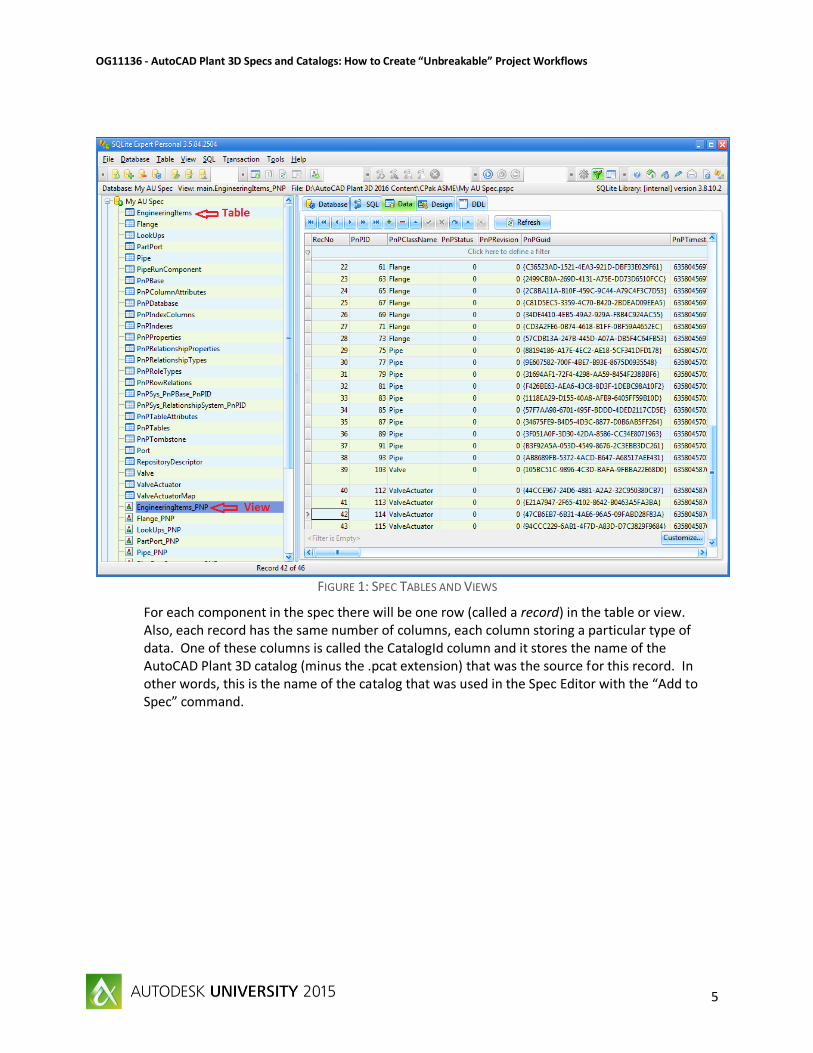
Updating the Spec Parts with Catalog Updates With the AutoCAD Plant 3D Spec Editor you can make changes to the catalog or spec as well as synchronize the data between the two. If a spec is opened in the editor, and a part from one of its catalogs has been changed in the catalog, those changes can be propagated to the spec by using the pull-down menu command “Specs > Check for Updates from Catalogs” shown in Figure 6 below.
Updating a spec from a catalog can overwrite changes you have made to the spec part properties.
Important Fact #2
OG11136 - AutoCAD Plant 3D Specs and Catalogs: How to Create “Unbreakable” Project Workflows
10
FIGURE 6: UPDATING A SPEC WITH CATALOG CHANGES
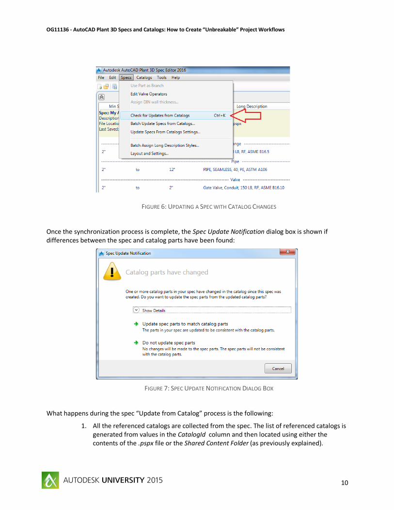
Once the synchronization process is complete, the Spec Update Notification dialog box is shown if differences between the spec and catalog parts have been found:
FIGURE 7: SPEC UPDATE NOTIFICATION DIALOG BOX
What happens during the spec “Update from Catalog” process is the following:
1. All the referenced catalogs are collected from the spec. The list of referenced catalogs is generated from values in the CatalogId column and then located using either the contents of the .pspx file or the Shared Content Folder (as previously explained).

OG11136 - AutoCAD Plant 3D Specs and Catalogs: How to Create “Unbreakable” Project Workflows
11
2. A part in the spec is matched with a part in the catalog using its SizeRecordID column value. Multiple parts in the spec can have the same SizeRecordID value, while only one part in the catalog can.
3. All column values in the spec (except system values) are compared and differences reported. A property is compared if:
a. it is checked in the Update Spec From Catalog Settings dialog, and b. it is present in both the spec and catalog.
4. The user is shown the Spec Update Notification dialog box and can choose to review and either accept or reject the updates to the spec.
The settings for what properties are compared and subsequently synchronized are located in the AutoCAD Plant 3D Spec Editor pull-down menu “Specs > Update Specs from Catalog Settings” command.
FIGURE 8: UPDATE SPECS FROM CATALOG SETTINGS

OG11136 - AutoCAD Plant 3D Specs and Catalogs: How to Create “Unbreakable” Project Workflows
12
It is important to establish workflows that support effective use of the spec and catalog synchronization. For example, if you have established a spec-building procedure that uses the Property Overrides in the Spec Editor to add Material, Material Code or Schedule to your catalog items as they are inserted into a spec, you will want to be sure to deselect those properties from the Update Specs from Catalog Settings. Otherwise, the first time you run the “Check for Updates from Catalogs” command it will overwrite your spec values with whatever values are in the catalog, even if they are blank (which they most likely would be in this scenario).
FIGURE 9: PROPERTY OVERRIDES IN SPEC EDITOR
There is one final command that can help you manage the spec and catalog synchronization available from the AutoCAD Plant 3D Spec Editor pull-down menu: “Specs > Batch Update Specs from Catalogs”. This command will allow you to select multiple specs and have each updated with the current catalog values based upon the current Update Specs from Catalog Settings. This batch process does not pause for user verification before performing the updates to the specs, so it is strongly recommended that you don’t use this command until you are confident in your spec updating workflows as well as in the data contained within the catalogs.

OG11136 - AutoCAD Plant 3D Specs and Catalogs: How to Create “Unbreakable” Project Workflows
13
FIGURE 10: BATCH UPDATE SPECS FROM CATALOGS
Examining the Model-Spec Connection Now that we have a thorough understanding of how the spec-catalog relationship is managed, it is time to understand how the relationship between the 3D model parts stay connected to the parts in the spec that they came from.
Where do I look in the spec and project database for my components and their IDs? Much like the how the SizeRecordID is used to connect a spec part with a catalog part, the AutoCAD Plant 3D software uses the PnPID of the part in the spec to relate it to the SpecRecordID in the project database. However, there are two differences with these IDs:
1. They are not GUIDs, but rather a numeric sequential ID. This incremental number is unique within the project and spec, but not globally.
2. They are located within the project database in two places: a. In the PipeRunComponent table, where the PnPID is the unique ID for the item
in the project database and the SpecRecordID is associated with it. This is not a good place to look at the items though, because there is no descriptive information telling us specifics about the part (i.e. whether it is a flange, pipe, etc.).
b. In the view for the specific item types; for example, the Flange_PNP view (shown in Figure 11 below) shows the relationship between the flanges in the project database and the SpecRecordIDs (which are the PnPID unique IDs for the parts in the spec database).

OG11136 - AutoCAD Plant 3D Specs and Catalogs: How to Create “Unbreakable” Project Workflows
14
FIGURE 11: PROJECT DATABASE AND SPEC DATABASE
As you can see above, the Spec and SpecRecordID in the project database specifically associates the part in the 3D model with the PnPID in the spec. This brings up a very important fact to remember:
Later in this class, we will cover some workflows to allow you to update items in the spec without breaking the connections to the 3D model. The primary things to note here are:
The spec name is important to the connection with the 3D model; if you rename the spec it won’t be connected with the original part(s) in the 3D model. We will cover a workflow later on how to rename a spec and keep it connected with parts in the project 3D model(s). Also, if the spec is moved from the project specs folder, it won’t be found by Plant 3D.
The PnPID of the parts in the spec are auto-generated by the Spec Editor when parts are added to the spec. Therefore, once you remove a part from the spec you have “broken” that connection to the 3D model. Even rebuilding the spec with the same catalog parts doesn’t
Each time a part is added to a spec, it gets assigned a new PnPID ID number. This is the same number that connects it to parts in the 3D model. Deleting a part from a spec will permanently prevent the associated 3D model parts from being able to be updated from the spec.
Important Fact #3

OG11136 - AutoCAD Plant 3D Specs and Catalogs: How to Create “Unbreakable” Project Workflows
15
guarantee that you will get the same PnPID numbers auto-generated within the spec. A proper workflow for modifying specs will be covered in a later section of this class.
You can use the AutoCAD COPY, ARRAY, etc. to create new instances of a part in the 3D model and the new parts will have the same Spec and SpecRecordID of the original part. In other words, there is a “one to many” relationship between a spec part and the associated model parts. It is common for multiple parts in the 3D model to be associated with one part in the spec. This just underlines the importance of having the correct workflows when modifying specs: change one thing incorrectly and you end up having to fix many things later.
The next section will explain the steps involved in updating AutoCAD Plant 3D models with spec changes and give you a deeper understanding of what is happening within the software.
Updating the Model with Spec Changes
Controlling How and When AutoCAD Plant 3D Checks for Spec Updates When a user opens a project 3D model from Project Manager, AutoCAD Plant 3D is (by default) configured to automatically check for updates to specs that are referenced in the drawing and notify the user if about them. In this section we will look at the AutoCAD variables and commands involved in this process and then we will break it down to see what conditions trigger a spec update and how the various dialog boxes work.
First, there are two system variables and one command related to spec updates within the model:
PLANTSPECNOTIFY – This variable is stored in the registry and can be set to either 1 or 0. If it is set to 1, AutoCAD Plant 3D will check for spec file updates (by essentially running the PLANTSPECUPDATECHECK command) when the drawing loads, and on the time interval specified by the PLANTSPECNOTIFYTIME system variable. Default=1.
PLANTSPECNOTIFYTIME – This variable is also stored in the registry and can be set to an integer value of 0 through 4. The value indicates the time interval (in hours) that spec files are checked for updates. The first check will always be made when the drawing is loaded, regardless of the value. Default=2.
PLANTSPECUPDATECHECK – This command will force an immediate check for changes to a pipe spec that is used in the 3D model that is currently being edited. If changes are discovered, you can update the model.
When PLANTSPECUPDATECHECK runs, the main steps in the synchronization process are as follows:
1. Plant 3D builds a list of referenced specs from the project database for parts in the drawing. 2. It then checks a time stamp in the drawing database with that in the spec database. If the spec
database time stamp is newer it proceeds to the next step. If a spec doesn’t have an updated time stamp then it is skipped.
3. Plant 3D finalizes its internal list of specs that have been updated. 4. It then creates a list of all of the parts in the drawing which reference each of the updated specs.
It compares the IDs (as described in the previous section) to be sure that the part is in both the spec and model.
5. Once it verifies that the corresponding IDs match, it compares the properties of the part in the model with the part in the spec. It ignores system properties and only compares those

OG11136 - AutoCAD Plant 3D Specs and Catalogs: How to Create “Unbreakable” Project Workflows
16
properties that are specified under “Project Setup > Plant 3D DWG Settings > Spec Update Settings”:
FIGURE 12: PROJECT SETUP – SPEC UPDATE SETTINGS
6. Non-graphical and graphical properties are compared independently. All instances of a part in the project are affected if a non-graphical property is updated in the spec. Examples of non-graphical properties would be the Manufacturer or PartSizeLongDesc. If a Geometric property (parametric values) is updated in the spec, only the part instances in the current open drawing are updated. The PLANTSPECUPDATECHECK command must be run individually on all drawings in the project to force a redraw of geometric changes.
7. Once the synchronization analysis is complete the user will be presented with the Spec Update Notification dialog (shown below). This dialog only applies to non-graphical changes in the model, so accepting the updates will only synchronize non-graphical, descriptive data changes:

OG11136 - AutoCAD Plant 3D Specs and Catalogs: How to Create “Unbreakable” Project Workflows
17
FIGURE 13: SPEC UPDATE AVAILABLE DIALOG
The dialog can be a little misleading in that it seems to imply that it will only make changes to the model that is currently open, but don’t be fooled: every model in the project will be updated with the non-graphical spec changes. However, only changes for specs referenced in the open model will happen. Example: If the open model has specs A, B and C and specs A, B and D have changed, then only non-graphical information for A and B will be updated in all models in the project. Any models that reference spec D must be opened from Project Manager and then PLANTSPECUPDATECHECK will run automatically and update those models.
8. Next, if geometric changes have been made in the spec there is a second dialog that appears. This dialog may be docked at the bottom of your screen and, as such is missing a key piece of information that indicates its function: the dialog name. Undocked, it appears as shown in figure 14 below:
FIGURE 14: DIMENSIONAL SPEC UPDATE DIALOG

OG11136 - AutoCAD Plant 3D Specs and Catalogs: How to Create “Unbreakable” Project Workflows
18
By selecting the check box and then selecting the Update Parts button, it will change the graphics of those parts to reflect the spec changes. To see the affected parts highlighted in the 3D model, select the “Show Parts” button for the part listed in the dialog. When finished, the dialog box must be closed manually. What constitutes a “graphical” change to the spec?
So, even though the “Edit Parts” button in the Spec Editor allows the user to edit text and numeric data that looks like dimensional data, this is not considered to be graphical data by AutoCAD Plant 3D and is easy to get “out of sync” by editing in this fashion. Figure 15 shows some examples of non-graphical data in the spec posing as dimensional parameters:
FIGURE 15: NON-GRAPHICAL DATA IN SPEC EDITOR
The correct way to initiate graphical spec changes is through the Catalog Editor: a. Select the part in the catalog b. Select the “Sizes” tab in the editor c. Modify Size Parameters in the right side of the screen (see Figure 16 below) d. Also modify any non-graphical data in the “Piping Component Properties” pane that
corresponds to your parameter changes. This is the data that appears in Figure 15 above. e. Save changes to Catalog f. Switch to the Spec Editor g. Use “Specs > Check for Updates from Catalogs” h. Accept changes and save the spec
Graphical changes to the spec can only be made by modifying the catalog and then updating the spec with changes from the catalog. For most parts, this is done within the “Size Parameters” part of the Catalog Editor.
Important Fact #4

OG11136 - AutoCAD Plant 3D Specs and Catalogs: How to Create “Unbreakable” Project Workflows
19
FIGURE 16: GRAPHICAL PARAMETERS IN CATALOG EDITOR
9. Finally, after incorporating the graphical changes you should review the updated items to repair any disconnects or piping layout changes that may have occurred due to the graphical changes.
If you are the spec administrator, you will need to not only understand the process described above but also communicate how this works to the design team responsible for incorporating the spec changes in the models. If the entire team has a good understanding of their part in this process, updating specs and having those changes propagate through the models into the deliverable construction documents will be an effective tool in managing changes during a project.
Maintaining Connections and Incorporating Catalog/Spec Changes in Models during a Project Although the previous section touched on the workflow for updating parts in the model, this section will complete the picture by exploring the complete workflows for the most common changes that occur during plant design projects with AutoCAD Plant 3D. For these workflows, we will identify two roles: “User” and “Admin”. The responsibilities of each role are typically:
“User” creates 3D models and generates project deliverables (isometric drawings, orthographic drawings and material takeoffs).
“User” may be responsible as part of the project execution team to communicate to “Admin” any spec changes which occur as a result of project decisions as well as schedule requirements (what changed and when the change needs to be made to the spec).

OG11136 - AutoCAD Plant 3D Specs and Catalogs: How to Create “Unbreakable” Project Workflows
20
“User” incorporates spec changes generated by “Admin” into 3D models in a timely fashion to avoid manual rework on project deliverables or re-issuing of documents due to late changes.
“User” needs to take responsibility for the design implications of spec changes as well as other downstream effects (re-ordering of materials, piping layout considerations, re-extracting isos, etc.).
“Admin” is responsible for making changes to specs and catalogs.
“Admin” should be aware of the impact of spec changes and communicate closely with the project team on the timing of incorporating changes to specs. This will help avoid unexpected changes in the middle of generating package deliverables.
“Admin” must understand all processes outlined in this class and implement workflows that support the capabilities of the AutoCAD Plant 3D and Spec Editor software.
“Admin” is responsible for maintaining backup copies of project specs and catalogs (and possibly revisions with supporting documentation).
These roles may be shared by some people on the project team, but typically are distinct to specific individuals - especially on larger projects. Now that the roles are defined, it is time to examine the critical workflows surrounding changing specs and catalogs while projects are underway.
Workflow Example: Updating Catalog Parts As with any workflow, it is important to identify “When does this apply?” before beginning the steps described therein. Whether to modify a catalog and update the spec from those changes or to manually modify the spec parts is an important fact to know before beginning to make any changes to either.
Catalog changes are typically made:
For completely new parts that are unavailable in another catalog. This includes new model numbers or manufacturers. This is especially true for any case where the dimensional parameters are different than in existing catalogs (e.g. valves and their operators).
For duplicating an existing catalog and adding client-specific data (e.g. SAP numbers).
When descriptive (non-graphical) or dimensional parameters (geometric) information is permanently changed for existing catalog parts. This would be updated with the intent of then updating all affected specs.
Manually changing the spec without changing the catalog from which it got its parts is a rarer instance, but is not completely uncommon. Spec changes are typically made:
If your company’s typical workflow is to apply property overrides (Material, Material Code and Schedule) to items that are inserted from the catalog. These properties may not exist in the catalog, and if you are using this workflow you have probably modified the “Update Specs from Catalog Settings” to not update those properties. If you haven’t done this yet, I recommend you do it soon.
For temporary or project-specific changes that don’t justify modifying the catalog. An example would be a special tagging note on valves that only applies to a certain project. In this case keep a copy of the spec files in a separate location with documentation describing the differences in the spec contents.
Let’s examine the steps involved all the way from modifying the catalog through to updating the model. Below is a simplified workflow showing the steps in this process:

OG11136 - AutoCAD Plant 3D Specs and Catalogs: How to Create “Unbreakable” Project Workflows
21
FIGURE 17: WORKFLOW FOR PROPAGATING PART CHANGES IN CATALOG THROUGH SPEC TO 3D MODEL
Modifying Parts in the Catalog (all done by “Admin”)
1. Before editing, make a backup of the catalog (.pcat) file. 2. Open the catalog in the Catalog Editor 3. Find and highlight the items that need to be changed using the Catalog Browser (bottom
pane) 4. Change the data for the parts using the Piping Component Editor (top pane). Select the
Sizes tab to edit geometric parameters (with the Size Parameters pane) or size-specific non-graphical properties (with the Piping Component Properties pane).
5. Commit the changes to the catalog with the “Save to Catalog” button. This does not save the catalog file (.pcat) but saves the changes you make into the catalog that is currently loaded in the Catalog Editor, which is sufficient for using the “Specs > Check for Updates from Catalog” command.
6. Verify that the changes you made will be updated in the specs with the “Specs > Update Specs from Catalog Settings” command.
7. For a single spec, open it in the Spec Editor and run the “Specs > Check for Updates from Catalog” command. For multiple specs, run the “Specs > Batch Update Specs from Catalogs”.
8. Save (and close) the modified spec and catalog files.
Next let’s look at an example of a situation where you would keep a catalog item even though it is going to be radically changed. Assume that catalog “My Valves” contains the following valves that have been added to multiple specs and inserted into multiple 3D models in my project:
Long Description (Family) = Gate Valve, Conduit, 150 LB, RF, ASME B16.10

OG11136 - AutoCAD Plant 3D Specs and Catalogs: How to Create “Unbreakable” Project Workflows
22
Although this is a valid valve description (the manufacturer has it in their catalog) and you plan on using it in the future, currently every spec that references it needs to have this valve swapped out with a valve that has the following description:
Long Description (Family) = Gate Valve, Conduit, 150 LB, RF, ASME B16.10 NACE Trim Having the “User” replace every item in every model would be time consuming but is possible. Utilizing the Catalog > Spec > 3D Model connections to update these valves automatically would be preferred. To do this, you would follow these steps (all done by “Admin”):
1. Open the “My Valves” catalog in the Catalog Editor. 2. Find and highlight the “Gate Valve, Conduit, 150 LB, RF, ASME B16.10” valves in the Catalog
Browser 3. Right-click and select Copy (Ctrl-C) 4. Right-click again and select Paste (Ctrl-V). You should see a new set of valves appear with the
same Long Description (Family) except with “-Copy” appended on the end. If you don’t see them, be sure that your filters are set so that you would see both the original and new valves.
5. Select the original valves (without the “-Copy”) and modify the Long Description (Family) to include the “NACE Trim” on the end. Make this change under Piping Component Properties.
6. Select “Save to Catalog” to commit these changes to the “My Valves” catalog. By modifying these valves you maintain the connections with the existing specs and hence the parts in the 3D models. You can update the specs and have the users update their 3D models automatically.
7. Finally, go back and remove the “-Copy” from the new valve so that it now resembles the original valve, but is not connected to any spec or 3D model parts because it has a new SizeRecordID.
In summary, do:
Change items in the catalog that currently exist in specs and then update the specs. This will save time even if there are multiple changes in the catalog because of the time savings found when updating specs and models by maintaining current connections rather than current properties. This especially works if you need to add items to the catalog in the process of making the change (i.e. the new part doesn’t already exist in the catalog and is referenced in specs and models).
Don’t:
Delete items from your spec and then re-insert them from the catalog. This breaks the Spec > 3D Model connection for existing parts. If you must add items to a spec and need to remove the unwanted items, review the next workflow first to see if it provides a time-saving method of updating specs and models with existing catalog items.
Workflow Example: Adding Catalog Parts to Specs/Modifying Specs There will be situations where you have existing catalog parts that will need to be replaced in specs. Let’s use the following two valves in the “My Valves” catalog for this workflow example:
Long Description (Family) = Gate Valve, Conduit, 150 LB, RF, ASME B16.10 Long Description (Family) = Gate Valve, Double Disc, 150 LB, RF, ASME B16.10

OG11136 - AutoCAD Plant 3D Specs and Catalogs: How to Create “Unbreakable” Project Workflows
23
Let’s say that we have a spec called “My AU Spec” that has the conduit gate valve in it but we have to replace the conduit valve with the double disc gate valve – the conduit is no longer allowed to be used in that spec. However, not only has the conduit valve already been inserted many times in several 3D models, but several specs contain both of the valves shown above so making changes to either one in the catalog is not a viable option.
This scenario would be a good candidate for the following workflow that allows the catalogs to remain unchanged but still utilizes the Spec > 3D Model connections to perform updates to the parts in the 3D models.
Modifying Parts in the Spec (all done by “Admin” unless otherwise noted)
1. Before editing, make a backup of the spec (.pspc & .pspx) files. 2. Open the “My AU Spec” spec in the Spec Editor 3. Open the “My Valves” catalog in the catalog browser 4. Find and highlight the double disc gate valve that needs to be added to the spec using
the Catalog Browser (bottom pane). Be sure that the correct size range is selected, etc. 5. Select the “Add to Spec” button. Now both valves are in the spec:
FIGURE 18: BOTH GATE VALVES IN “MY AU SPEC”
6. Now, highlight the conduit valve in the Spec Editor (top pane). Since this valve is no
longer allowed in the spec but is still a valid part in the catalog, you have two choices:
a. Delete the valve from the spec. This will effectively “orphan” all instances of the valve in the project’s 3D models, not allowing it to be updated from the spec. If you do this, the “User” will have to find all of the conduit valves and delete them manually. This is the less preferred option.

OG11136 - AutoCAD Plant 3D Specs and Catalogs: How to Create “Unbreakable” Project Workflows
24
b. Modify the conduit valve’s description as described in the next step 7. With the conduit valve highlighted, select the “Edit Parts” button. Change the Long
Description (Family) to read: **OUT OF SPEC** Gate Valve, Conduit. You can also add “**OUT OF SPEC**” to the Long Description (Size) to make step 15 easier for “User”.
8. Select “Apply” and “OK” to close the Edit Parts dialog box. You should see your changes reflected in the Spec Editor.
9. Select “File > Save” to save the spec to the project. Steps 10 through 16 are performed by the “User” role:
10. Open one of the models in the project and run the “PLANTSPECUPDATECHECK” command.
11. Accept the changes to the parts. Remember that since these are non-graphical properties they will be updated for all models in the project.
12. Open Data Manager and set it to Current Drawing Data and Order by Object Type as shown in Figure 19.
13. Click on the Long Description (Family) header to sort by this value. This will group all of the “out of spec” items together as shown below:
FIGURE 19: DATA MANAGER SHOWING OUT OF SPEC VALVES
14. With the Zoom Toggle turned on (this is the green boxed button in Figure 19 above), click on the leftmost column next to one of the out-of-spec valves (indicated by the green arrow in Figure 19). This will zoom the display to be centered on that valve.
15. Select the valve in the 3D model and use the Substitute Part grip to substitute the double disc valve for the out-of-spec conduit valve. If “Admin” had modified the Long Description (Size) to also include **OUT OF SPEC** the choice is more obvious to “User”.
16. Repeat steps 10 through 15 for each 3D model.

OG11136 - AutoCAD Plant 3D Specs and Catalogs: How to Create “Unbreakable” Project Workflows
25
FIGURE 20: USING SUBSTITUTE PART GRIP TO REPLACE OUT-OF-SPEC PARTS IN 3D MODEL
In summary, do:
Leave items in the spec that currently exist in 3D models even if they are no longer allowed. Change their descriptions (to make them searchable in Data Manager) and then update the parts in the 3D model from the spec. This will save time and allow “User” to easily find and substitute the correct valves (which are also in the spec).
Don’t:
Delete items from your spec just because they are no longer allowed – instead change the description to indicate it is no longer a spec item. By leveraging the PLANTSPECUPDATECHECK command you can ensure that all out-of-spec parts are caught and replaced by “User”.
Workflow Example: Renaming a Spec Often times during a project the need arises to rename a spec (or several) and still maintain the connections with the project’s 3D models. This workflow is fairly simple due to the fact that by renaming the spec we are not modifying the IDs in the spec which correlate with the project database.
1. “Admin” opens the project spec in the AutoCAD Plant 3D Spec Editor and does a “File > Save As” to the new spec file name into the project’s spec folder. Do not make any other modifications to the spec since the new copy must be an exact duplicate of the original spec when changes are made in the 3D model by “User” in steps 3 through 5.

OG11136 - AutoCAD Plant 3D Specs and Catalogs: How to Create “Unbreakable” Project Workflows
26
2. “Admin” notifies users of new spec creation and that the old spec is going to be removed from the project at a given date. This gives “User” time to perform the next steps.
3. “User” opens model and identifies piping systems which were created using the old spec name. This can be done via Data Manager or through AutoCAD Layer control.
4. “User” selects entire piping systems that reference the old spec and change the Spec to the new spec name using the Properties palette.
5. “User” uses Data Manager to confirm that all piping systems referencing the old spec name have been updated in all project 3D models.
6. “Admin” receives verification from “User” that old spec is no longer referenced in 3D models and then removes the old spec from the project. It is recommended that a copy of the old spec be archived at this point.
FIGURE 21: USING PROPERTIES PALETTE TO CHANGE SPEC NAME IN 3D MODEL

OG11136 - AutoCAD Plant 3D Specs and Catalogs: How to Create “Unbreakable” Project Workflows
27
Do: Rename a spec with the “File > Save As” command in the AutoCAD Plant 3D Spec Editor. Then you would change the spec name using the Properties palette.
Summary Managing spec changes during the execution of a project, or multiple projects, requires simple but defined workflows that – once documented and understood by the entire team – can be effectively implemented with AutoCAD Plant 3D. I hope this document serves as a foundation for you to develop your own company workflows that will help your teams develop productive habits with the software and move you closer to successful project completions that are under budget and under schedule.