offsite groundwater phase ii investigation report … · offsite groundwater phase ii investigation...
TRANSCRIPT
' ' '00005
Offsite Groundwater Phase IIInvestigation Report
Electro-Voice, Inc.Buchanan, Michigan
Project Number F93307I
K i s h b <• i,' U , T h u ni p N cs n . Ji '• u r r 6t M (i h t- rK 11 i> i n i- c r s * S (.- i e u I i .s 1 s " A r r li i 1 r L' I
W7 fp r~"w (I fn
OFFSITE GROUNDWATER
PHASED INVESTIGATION
FOR
ELECTRO-VOICE, INC.BUCHANAN, MICHIGAN
September 1995Project No. F93307L
Prepared by:
FISHBECK, THOMPSON, CARR & HUBER, INC,6090 East Fulton, P.O. Box 211
Ada, Michigan 49301-0211(616) 676-2666
7402 Westshire Drive, Suite 110Lansing, Michigan 48917-9764
(517) 627-1141
tw-ORCEMENTSE. BRANCH
TABLE OF CONTENTS
Page
1.0 INTRODUCTION . . . . . . . . . . . . . . . . . . . . . . . . . . . . . . . . . . . . . . . . . . . . . . 11.1 Purpose . . . . . . . . . . . . . . . . . . . . . . . . . . . . . . . . . . . . . . . . . . . . . . . . 11.2 Background Information . . . . . . . . . . . . . . . . . . . . . . . . . . . . . . . . . . . . . . 11.3 Scope of Work . . . . . . . . . . . . . . . . . . . . . . . . . . . . . . . . . . . . . . . . . . . . 2
2.0 OFFSITE WORK . . . . . . . . . . . . . . . . . . . . . . . . . . . . . . . . . . . . . . . . . . . . . . . 32.1 Temporary Monitor Well Installation and Groundwater Sampling Methodology ... 32.2 Soil Boring Installation and Soil Sampling Methodology . . . . . . . . . . . . . . . . . . 4
2.2.1 Split-Spoon Soil Sampling . . . . . . . . . . . . . . . . . . . . . . . . . . . . . . . . 52.2.2 Hand Bucket Auger Sampling . . . . . . . . . . . . . . . . . . . . . . . . . . . . . 5
3.0 RESULTS OF INVESTIGATION . . . . . . . . . . . . . . . . . . . . . . . . . . . . . . . . . . . . 73.1 Temporary Monitor Well Installation . . . . . . . . . . . . . . . . . . . . . . . . . . . . . . 73.2 Soil Borings . . . . . . . . . . . . . . . . . . . . . . . . . . . . . . . . . . . . . . . . . . . . . 7
4.0 REFERENCES . . . . . . . . . . . . . . . . . . . . . . . . . . . . . . . . . . . . . . . . . . . . . . . . 8
List of Figures
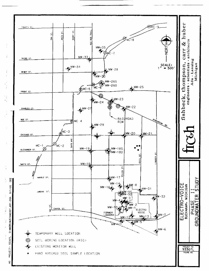
Figure 1 • Site Map - Monitor and Temporary Wells, and Soil Borings
List of Appendices
Appendix 1 • FTC&H SOPsAppendix 2 • Driller's Boring Logs - TW-1, TW-2 and OSB-l through OSB-4Appendix 3 • Groundwater and Soil Analytical Reports - Samples Collected July/August 1995
1.0 INTRODUCTION
1.1 Purpose
This report presents the findings of an offsite soil and groundwater Phase II investigation to identify
potential sources of contaminants that may have contributed to the groundwater contamination plume
identified downgradient of the Electro-Voice, Inc., Buchanan, Michigan facility.
1.2 Background Information
The Phase I report Offsite Groundwater Phase 1 Investigation for Electro-Voice, Inc., Buchanan,Michigan identified seven target properties as possible sources of contamination, along with a formergravel pit located between Red Bud Trail and Sylvan Street. Based upon the results of the Phase Iinvestigation, the following sites were investigated by sampling downgradient groundwater:
301 South Berrien Street - Refrigeration repair business
401 South Berrien Street - Former automotive repair garage405/407 Red Bud Trail - Former printer
306 South Red Bud Trail - Former automotive body repair garage
Based upon the results of the Phase I investigation, the following site was investigated for soilcontamination:
308 Cecil Street - Former automobile body shopGeneral area near monitor well Nos. 22 and 23.
Soil and groundwater sampling locations at each target property were selected based on the assumedlocation of the potential source area. Samples were collected from areas at or near the potential source
area, and/or between the potential source area and the identified groundwater plume.
09/07/95J:\DOC93\R93307UOFFSTEGW.RPT
1.3 Scope of Work
The work performed included temporary monitor well installation and associated groundwater sampling,
and soil boring and associated soil sampling.
09/07/95 - 2 -J:\DOC93\R93307L\OFFSTEGW.RPT
2.0 OFFSITE WORK
2-1 Temporary Monitor Well Installation and Groundwater Sampling Methodology
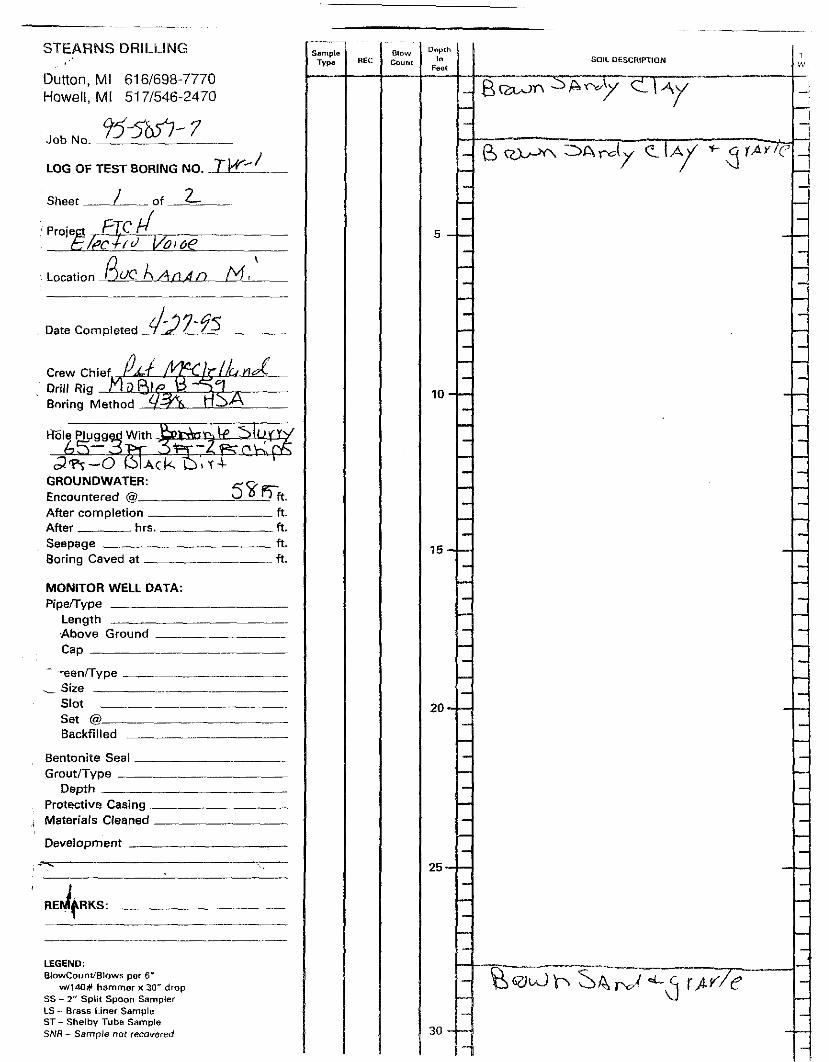
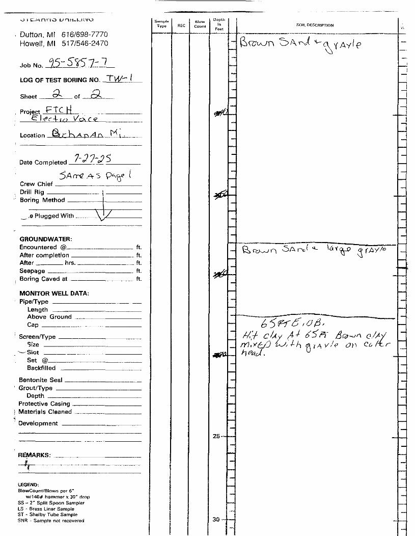
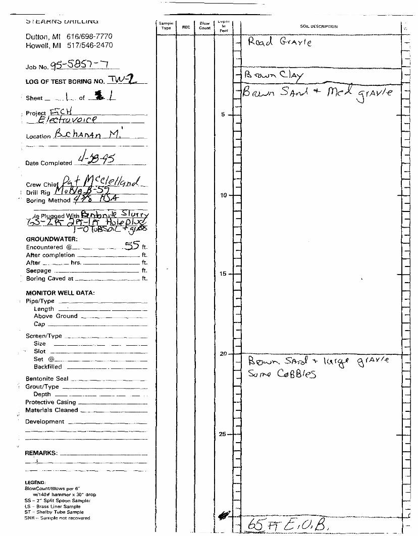
Two temporary monitor wells (TW-1 and TW-2) were installed along Chicago Street, downgradient fromthe facilities at 301 South Berrien Street (refrigeration repair business), 401 South Berrien Street (formerauto repair garage), 306 Red Bud Trail (former automotive repair garage), and 405/406 Red Bud Trail
(former printer). TW-1 and TW-2 were installed in the upper 5 to 10 feet of the aquifer. The locations
of the temporary monitor wells are presented on Figure 1. Data from the drilling and temporary wellinstallation were recorded in the field notebook and on specialized forms (Standard Operating Procedure[SOP] #F3-1) presented in Appendix 1.
The temporary monitor wells, TW-1 and TW-2, were advanced using 4.25-inch-diameter hollow-stemaugers. The temporary wells were logged based upon soil cuttings and changes in drilling pressure. Atemporary 2-inch-diameter, galvanized steel well casing, equipped with a 2-inch-diameter, 5-foot-long,
No. 7 slot size, stainless-steel well screen was used to obtain each groundwater sample. The temporarymonitor well was installed through the hollow-stem augers to the selected depth. The augers wereretracted 2 to 3 feet above the screened interval allowing the formation to collapse.
The temporary wells were developed using a Grundfos pump. Purging continued until the appearanceof the water became clear or visibly free of fines. Three consecutive samples of water were collected
and measured for specific conductance. The samples were considered to be representative of the aquiferwhen the three samples had a specific conductance that was ±10% of the first sample.
Groundwater samples for laboratory analysis were collected from the temporary well using adecontaminated Teflon bailer and disposable, cotton-bailer cord. The bailer was equipped with a bottom
check valve and had a volume of one liter. The bailer was conditioned to the groundwater by collectingand discarding five bailer volumes of groundwater prior to collection of the sample.
Samples for field parameter analysis were collected in 250-mi',liliter (ml) plastic bottles and analyzedonsite, as soon as possible. The groundwater samples were analyzed in the field for temperature, specificconductance, and pH in accordance with SOPs #F2-1, #F2-2, and #F2-3, respectively (Appendix 1).
09/07/95 . - 3 -J:\DOC()3\R93307L\OFFSTIiGW.RP'r
Groundwater samples for laboratory analysis were collected in accordance with SOPs #F4-1 and #F4-4
(Appendix 1). Groundwater samples were collected in 40-ml vials and packed on ice in an appropriate
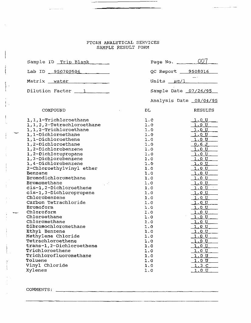
shipping container. A trip-blank was prepared for the shipping container. One field duplicate, one fieldblank, one matrix spike, and one matrix spike duplicate sample was also collected for laboratory analysis.
The samples were delivered to FTC&H Analytical under Chain-of-Custody procedures (SOP#F3-2)(Appendix 1) for analysis for volatile organic compounds (VOCs) usingU.S. EnvironmentalProtection Agency (EPA) Methods 8010/8020.
The temporary well sections were steam cleaned between locations. The Teflon bailer used to collect thegroundwater samples was washed with a trisodium phosphate solution and rinsed with deionized water.New bailer cord was used for each sample.
Soil cuttings were containerized. Groundwater removed from the temporary wells during developmentand groundwater sampling was temporarily containerized onsite. Upon completion of groundwatersampling, the containerized groundwater was discharged into the temporary well. The borehole was then
abandoned with a bentonite slurry. The slurry was pumped into the augers using a tremie hose. Thebentonite grout was allowed to fill the augers from the bottom of the boring to the top of the augers. Asthe augers were retracted, additional grout was added to provide a constant head on the formation as theaugers were retracted.
A temporary decontamination area was constructed at the rear of the Electro-Voice facility. Augers and
related drilling equipment were steam cleaned between wells using a high-pressure steam cleaner. The
drillers boring logs of temporary monitor wells TW-1 and TW-2 are presented in Appendix 2.
2.2 Soil Boring Installation and Soil Sampling Methodology
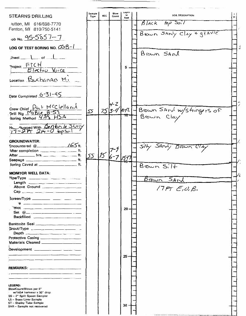
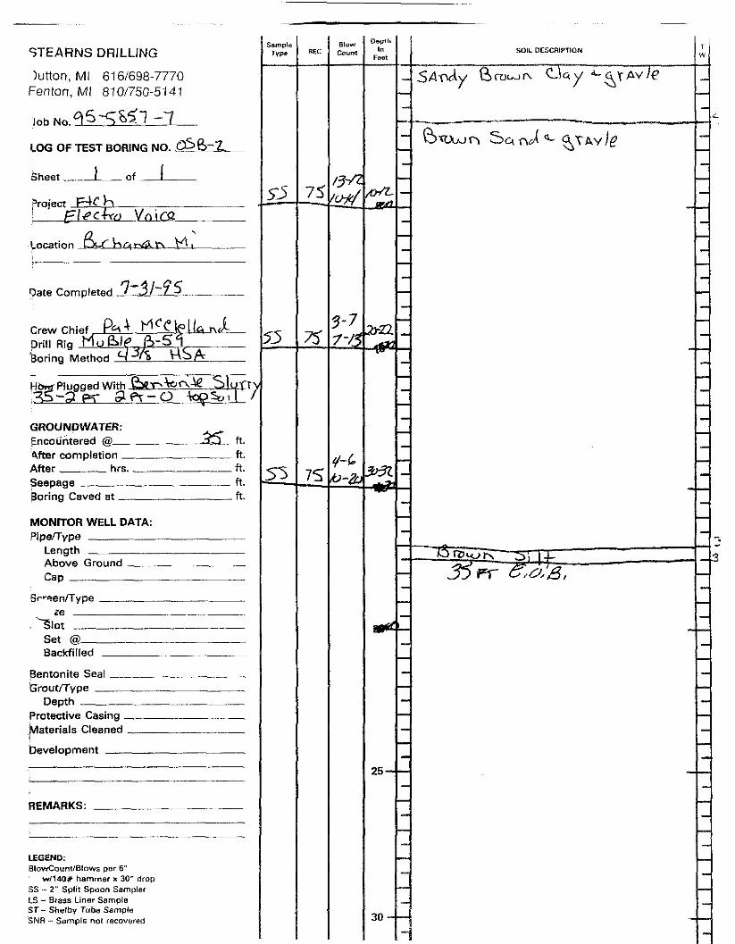
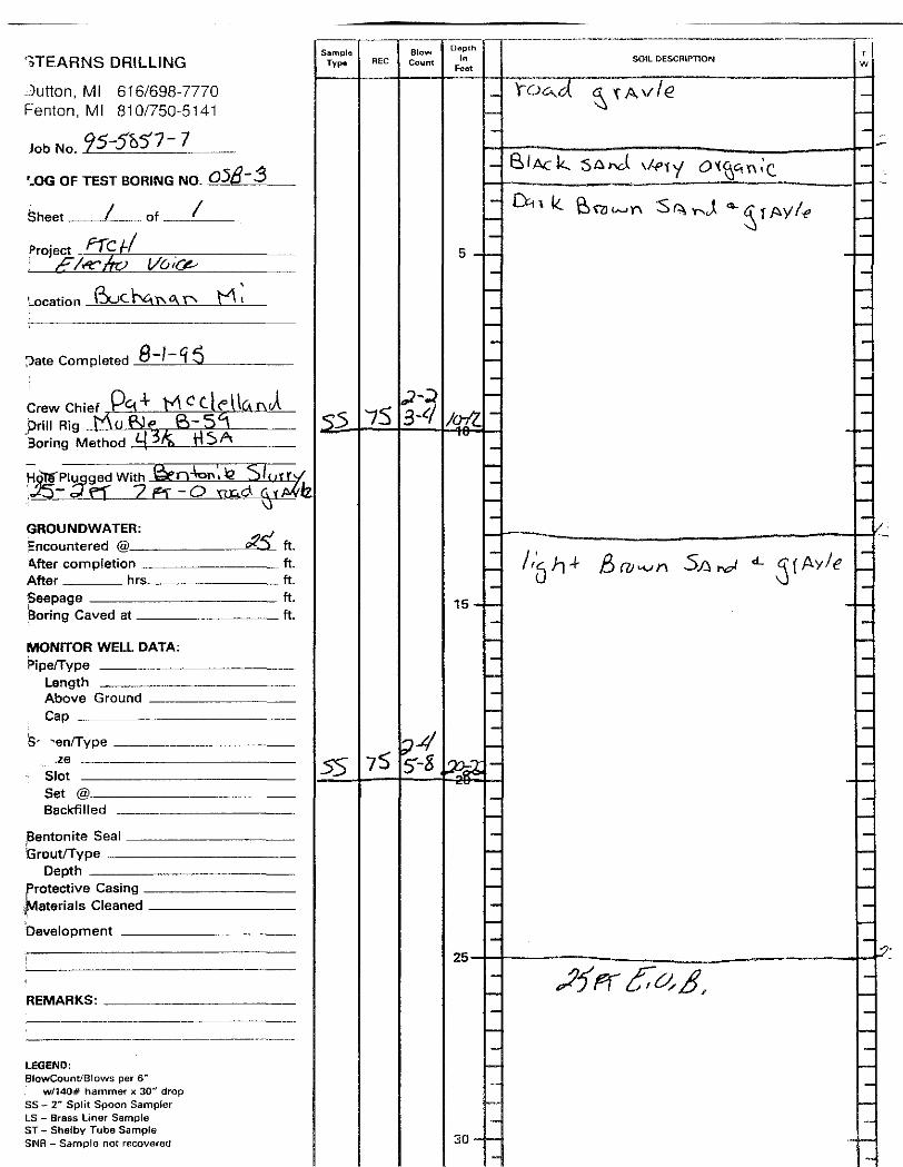
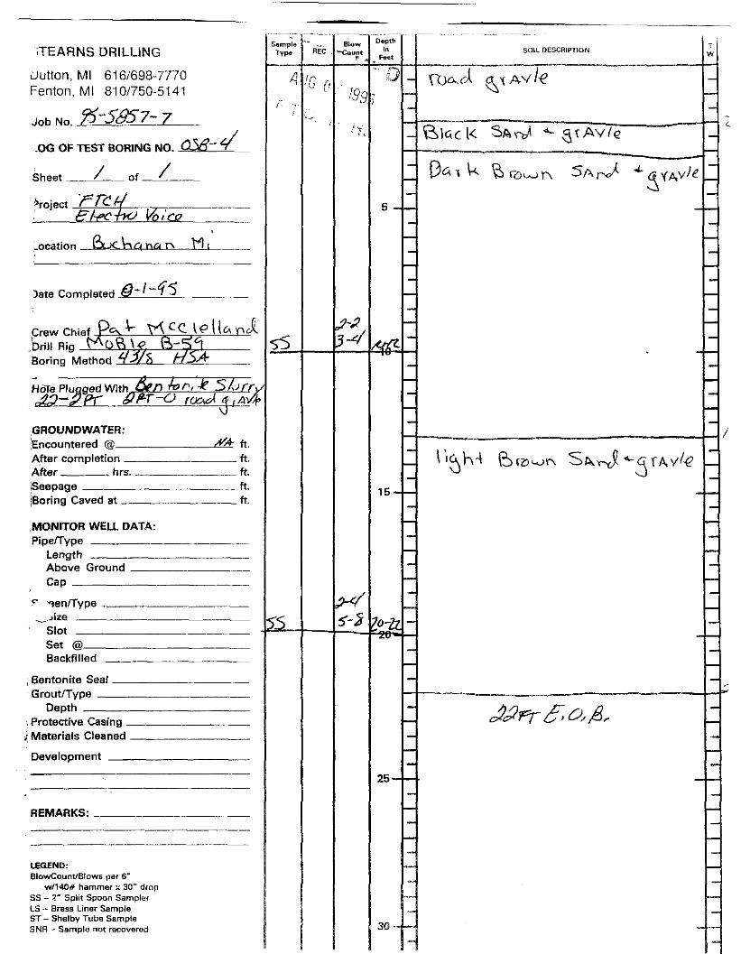
Soil borings were conducted at eight locations. Soil borings OSB-1 through OSB-4 were installed usinga truck-mounted drill rig and hollow-stem augers. OSB-1 and OSB-2 were installed in the street right-of-way along Rynearson Road. OSB-3 and OSB-4 were installed in the abandoned railroad right-of-way
south of Rynearson Road (in the vicinity of the former gravel pit). Soil borings OSB-5 through OSB-8were installed using hand auger equipment. OSB-5 and OSB-8 were installed near a garage at 308 Cecil
Street that was once used as an automobile body shop. The locations of the soil borings are presentedon Figure 1.
09/07/95 - 4 -J:\DOC93\R93307L\OFFSTEGW.RPT
2.2.1 Split-Spoon Soil Sampling
Soil borings OSB-1 through OSB-4 were advanced using hollow-stem augers. Two soil samples were
collected within each boring using a 2-inch-diameter, 2-foot-Iong, split-barrel sampler driven by a 160-
pound hammer. Only one split-spoon soil sample was collected from OSB-1. The augers were drilledto the desired depth and a split-spoon was driven approximately 2 feet ahead of the lead auger. Soilsamples were placed in appropriate bottles and packed on ice. One field duplicate was collected forlaboratory analysis. The samples were delivered to FTC&H Analytical under Chain-of-Custodyprocedures (SOP #F3-2)(Appendix 1) for analysis for VOCs using EPA Methods 8010/8020. Data from
the drilling and soil sampling were recorded in the field notebook and on specialized forms (SOP #F3-1)presented in Appendix 1.
Soil cuttings were containerized. The borehole was then abandoned with a bentonite slurry. The slurrywas pumped into the augers using a tremie hose. The bentonite grout was allowed to fill the augers from
the bottom of the boring to the top of the augers. As the augers were retracted, additional grout wasadded to provide a constant head on the formation as the augers were retracted.
The split-barrel sampler was decontaminated between collection of each sample by scrubbing with an
Alconox and water solution followed by a clean water rinse. Augers and related drilling equipment weresteam cleaned between wells using a high-pressure steam cleaner. The drillers boring logs of soil boringOSB-1 through OSB-4 are presented in Appendix 2,
2.2.2 Hand Bucket Auger Sampling
Soil borings OSB-5 through OSB-8 were advanced using hand auger equipment in accordance with SOP#F6-4. One soil sample was collected from each boring from the depth interval 8.5 to 9.0 feet below
ground level. Soil samples were collected in appropriate bottles and packed on ice. The samples were
delivered to FTC&H Analytical under Chain-of-Custody procedures (SOP #F3-2)(Appendix 1) foranalysis for VOCs using EPA Methods 8010/8020. Data from the drilling and soil sampling were
recorded in the field notebook and on specialized forms (SOP #F3-1) presented in Appendix 1.
09/07/95 - 5 -J:\DOC93\R93307L\OFFSTEGW.RPT
Soil cuttings were containerized. The borehole was then abandoned by backfilling with bentonite chips.
All hand auger equipment was decontaminated between borings by scrubbing with a trisodium phosphateand water solution followed by a clean water rinse or steam cleaning.
09/07/95 - 6 -J:VDOC93\R93307L\OFFSTEOW.RPT
3.0 RESULTS OF INVESTIGATION
3.1 Temporary Monitor Well Installation
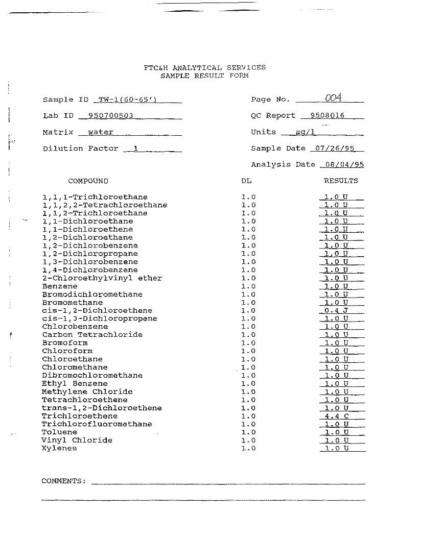
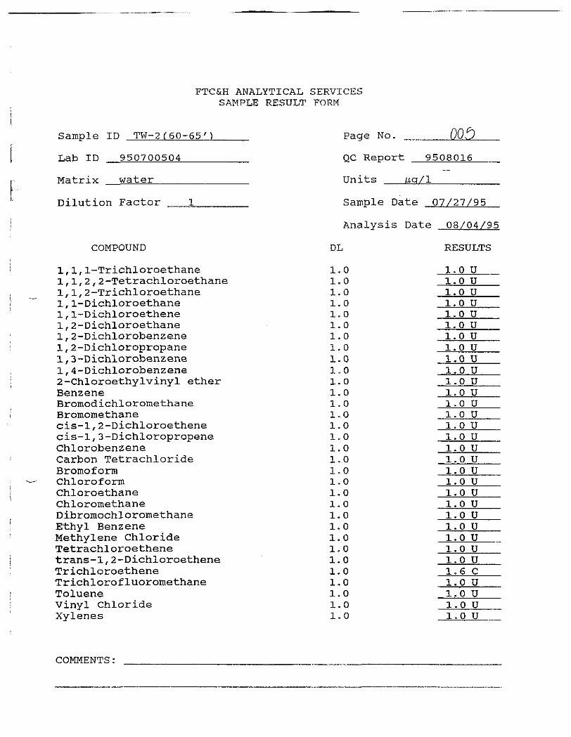
The results from the temporary monitor weli sampling are presented in Appendix 3. At location TW-1,trichloroethene (TCE) was detected at a concentration of 4.4 micrograms per liter (/ig/1). The only other
compound detected was cis-l,2-dichloroethene at an estimated concentration of 0.4 /tg/1. At location TW-3, only TCE was detected at a concentration of 1.6 /ig/I.
3.2 Soil Borings
No compounds were detected above the detection limit in any of the soil samples collected from theborings.
3.3 Evaluation
The results from the temporary well sampling and the soil sampling indicate that the identified potential
sources are not currently contributing to the contamination near MW-22 and MW-23.
09/07/95 - 7 -l:\DOC93\R93307L\OFFSTEGW.Rpr
4.0 REFERENCES
FTC&H, Offsite Groundwater Phase I Investigation For Electro-Voice, Inc., Buchanan, Michigan,Consultants Report, June 1995.
09/07/95J:\DOC93\R93307L\OFFSTEGW.RPT
SCALE:1 " = 500'
-Q-MW-6
TEMPORARY WELL LQCATfQN
SQiL. BORING LOCATION (RIG)
E X I S T I N G MONITOR WELL
HAND AUGERED SOIL SAMPLE LOCATION
ber
&fi
shb
eck
, th
om
pso
n,
carr
eng
inee
rs •
sci
enti
sts
• ar
chi
Ad
a * L
an
sin
gM
ich
igan
£> r I
AA
UJ -<-> <>_ OO I>^
I 2o .trzti
CEL
EBU
PH
AS
E I
IG
ROUN
DWAT
ER
STUD
Y
PHDJECT MO
93307L
FISHBECK, THOMPSON, CARR & HUBER, INC.STANDARD OPERATING PROCEDURE
FIELD MEASUREMENT OF pH BY ELECTRODESOP #F2-1Page 1 of 2Version 1.2Date: 4/7/94
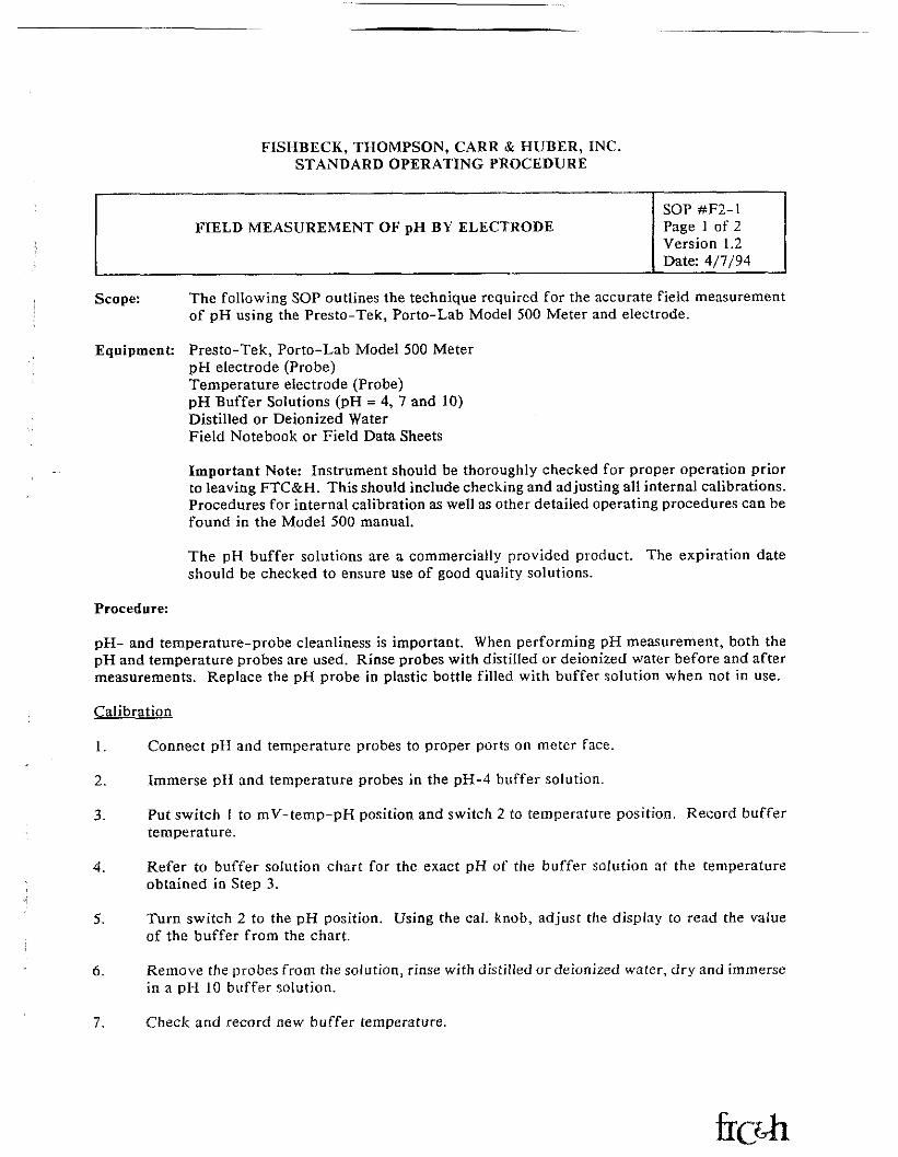
Scope: The following SOP outlines the technique required for the accurate field measurementof pH using the Presto-Tek, Porto-Lab Model 500 Meter and electrode.
Equipment: Presto-Tek, Porto-Lab Model 500 MeterpH electrode (Probe)Temperature electrode (Probe)pH Buffer Solutions (pH = 4, 7 and 10)Distilled or Deionized WaterField Notebook or Field Data Sheets
Important Note: Instrument should be thoroughly checked for proper operation priorto leaving FTC&H. This should include checking and adjusting all internal calibrations.Procedures for internal calibration as well as other detailed operating procedures can befound in the Model 500 manual.
The pH buffer solutions are a commercially provided product. The expiration dateshould be checked to ensure use of good quality solutions.
Procedure:
pH- and temperature-probe cleanliness is important. When performing pH measurement, both thepH and temperature probes are used. Rinse probes with distilled or deionized water before and aftermeasurements. Replace the pH probe in plastic bottle filled with buffer solution when not in use.
Calibration
1. Connect pH and temperature probes to proper ports on meter face.
2. Immerse pH and temperature probes in the pH-4 buffer solution.
3. Put switch \ to mV-temp-pH position and switch 2 to temperature position. Record buffertemperature.
4. Refer to buffer solution chart for the exact pH of the buffer solution at the temperatureobtained in Step 3.
5. Turn switch 2 to the pH position. Using the cal. knob, adjust the display to read the valueof the buffer from the chart.
6. Remove the probes from the solution, rinse with distilled or deionized water, dry and immersein a pH 10 buffer solution.
7. Check and record new buffer temperature.
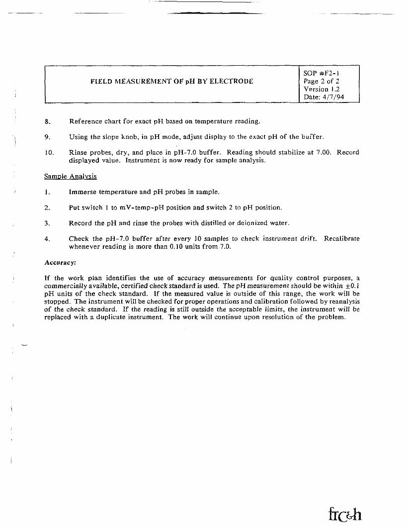
FIELD MEASUREMENT OF pH BY ELECTRODESOP#F2~1Page 2 of 2Version 1.2Date: 4/7/94
8. Reference chart for exact pH based on temperature reading.
9. Using the slope knob, in pH mode, adjust display to the exact pH of the buffer.
10. Rinse probes, dry, and place in pH-7.0 buffer. Reading should stabilize at 7.00. Recorddisplayed value. Instrument is now ready for sample analysis.
Sample Analysis
1. Immerse temperature and pH probes in sample.
2. Put switch 1 to mV-temp-pH position and switch 2 to pH position.
Record the pH and rinse the probes with distilled or deionized water.3.
4. Check the pH-7.0 buffer after every 10 samples to check instrument drift. Recalibratewhenever reading is more than 0,10 units from 7.0.
Accuracy:
If the work plan identifies the use of accuracy measurements for quality control purposes, acommercially available, certified check standard is used. The pH measurement should be within ±0.1pH units of the check standard. If the measured value is outside of this range, the work will bestopped. The instrument will be checked for proper operations and calibration followed by reanalysisof the check standard. If the reading is still outside the acceptable limits, the instrument will bereplaced with a duplicate instrument. The work will continue upon resolution of the problem.
FISHBECK, THOMPSON, CARR & HUBER, INC.STANDARD OPERATING PROCEDURE
FIELD MEASUREMENT OF SPECIFIC CONDUCTANCEBY ELECTRODE
SOP #¥2-2Page 1 of 2Version 1.2Date: 10/04/90
Scope:
Equipment:
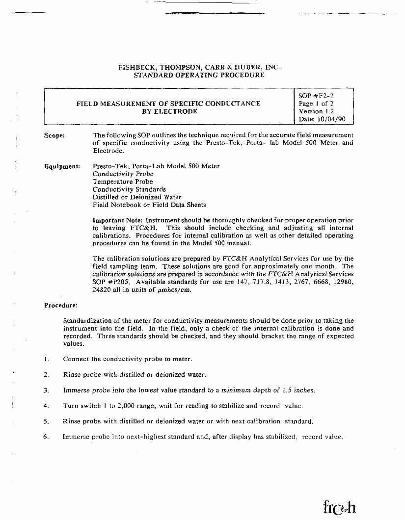
The following SOP outlines the technique required for the accurate field measurementof specific conductivity using the Presto-Tek, Porta- lab Model 500 Meter andElectrode.
Presto-Tek, Porta-Lab Model 500 MeterConductivity ProbeTemperature ProbeConductivity StandardsDistilled or Deionized WaterField Notebook or Field Data Sheets
Important Note: Instrument should be thoroughly checked for proper operation priorto leaving FTC&H. This should include checking and adjusting all internalcalibrations. Procedures for internal calibration as well as other detailed operatingprocedures can be found in the Model 500 manual.
The calibration solutions are prepared by FTC&H Analytical Services for use by thefield sampling team. These solutions are good for approximately one month. Thecalibration solutions are prepared in accordance with the FTC&H Analytical ServicesSOP #P205. Available standards for use are 147, 717.8, 1413, 2767, 6668, 12980,24820 all in units of /unhos/cm.
Procedure:
Standardization of the meter for conductivity measurements should be done prior to taking theinstrument into the field. In the field, only a check of the internal calibration is done andrecorded. Three standards should be checked, and they should bracket the range of expectedvalues.
1. Connect the conductivity probe to meter.
2. Rinse probe with distilled or deionized water.
3. Immerse probe into the lowest value standard to a minimum depth of 1.5 inches.
4. Turn switch 1 to 2,000 range, wait for reading to stabilize and record value.
5. Rinse probe with distilled or deionixed water or with next calibration standard.
6. Immerse probe into next-highest standard and, after display has stabilized, record value.
FIELD MEASUREMENT OF SPECIFIC CONDUCTANCEBY ELECTRODE
SOP #F2-2Page 2 of 2Version 1.2Date: 10/04/90
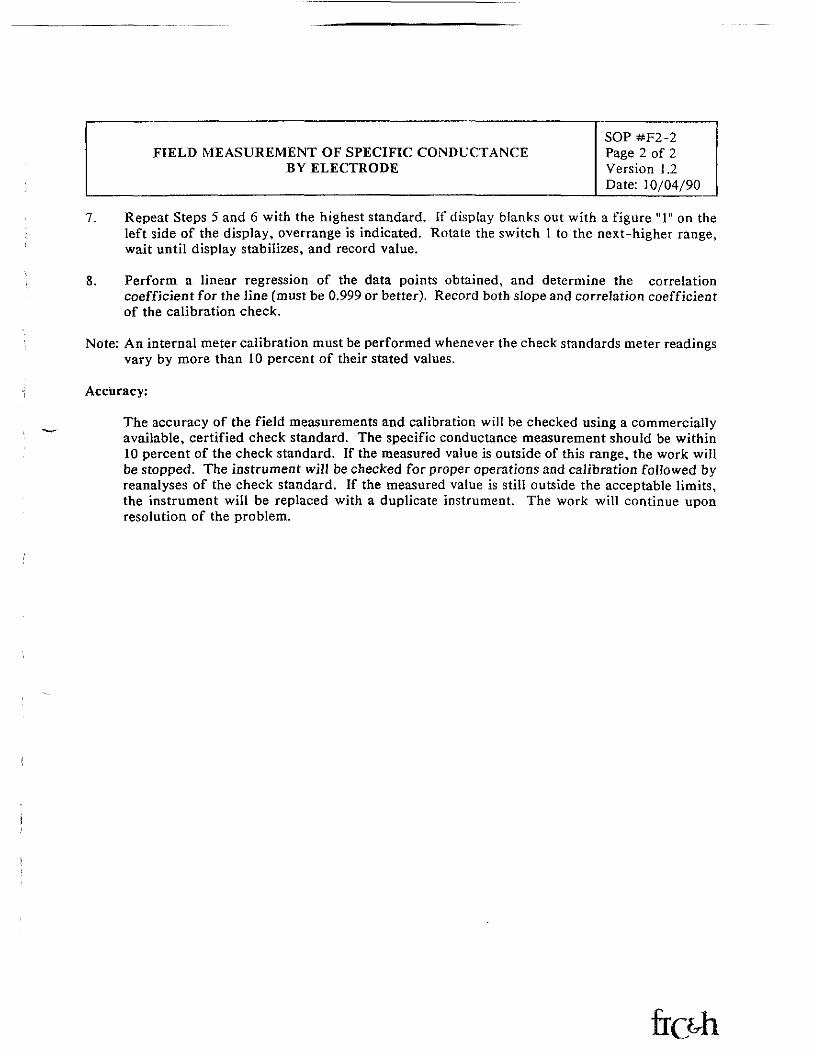
7. Repeat Steps 5 and 6 with the highest standard. If display blanks out with a figure "1" on theleft side of the display, overrange is indicated. Rotate the switch 1 to the next-higher range,wait until display stabilizes, and record value.
8. Perform a linear regression of the data points obtained, and determine the correlationcoefficient for the line (must be 0.999 or better). Record both slope and correlation coefficientof the calibration check.
Note: An internal meter calibration must be performed whenever the check standards meter readingsvary by more than 10 percent of their stated values.
Accuracy:
The accuracy of the field measurements and calibration will be checked using a commerciallyavailable, certified check standard. The specific conductance measurement should be within10 percent of the check standard. If the measured value is outside of this range, the work willbe stopped. The instrument will be checked for proper operations and calibration followed byreanalyses of the check standard. If the measured value is still outside the acceptable limits,the instrument will be replaced with a duplicate instrument. The work will continue uponresolution of the problem.
FISHBECK, THOMPSON, CARR & HUBER, INC.STANDARD OPERATING PROCEDURE
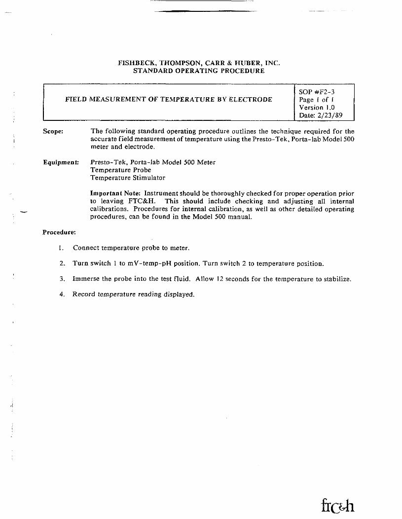
FIELD MEASUREMENT OF TEMPERATURE BY ELECTRODESOP #F2-3Page 1 of IVersion 1.0Date: 2/23/89
Scope: The following standard operating procedure outlines the technique required for theaccurate field measurement of temperature using the Presto-Tek, Porta-lab Model 500meter and electrode.
Equipment: Presto-Tek, Porta-lab Model 500 MeterTemperature ProbeTemperature Stimulator
Important Note: Instrument should be thoroughly checked for proper operation priorto leaving FTC&H. This should include checking and adjusting all internalcalibrations. Procedures for internal calibration, as well as other detailed operatingprocedures, can be found in the Model 500 manual.
Procedure:
1. Connect temperature probe to meter.
2. Turn switch 1 to mV-temp-pH position. Turn switch 2 to temperature position.
3. Immerse the probe into the test fluid. Allow 12 seconds for the temperature to stabilize.
4. Record temperature reading displayed.
FISHBECK, THOMPSON CARR & HUBER, INC.STANDARD OPERATING PROCEDURE
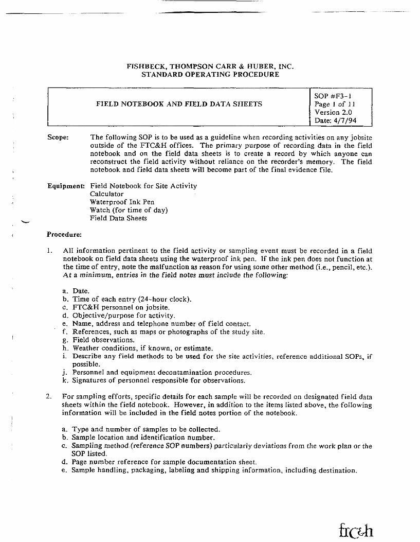
FIELD NOTEBOOK AND FIELD DATA SHEETSSOP#F3-1Page 1 of 1 1Version 2.0Date: 4/7/94
Scope: The following SOP is to be used as a guideline when recording activities on any jobsiteoutside of the FTC&H offices. The primary purpose of recording data in the fieldnotebook and on the field data sheets is to create a record by which anyone canreconstruct the field activity without reliance on the recorder's memory. The fieldnotebook and field data sheets will become part of the final evidence file.
Equipment: Field Notebook for Site ActivityCalculatorWaterproof Ink PenWatch (for time of day)Field Data Sheets
Procedure:
All information pertinent to the field activity or sampling event must be recorded in a fieldnotebook on field data sheets using the waterproof ink pen. If the ink pen does not function atthe time of entry, note the malfunction as reason for using some other method (i.e., pencil, etc.).At a minimum, entries in the field notes must include the following:
a. Date.b. Time of each entry (24-hour clock).c. FTC&H personnel on jobsite.d. Objective/purpose for activity.e. Name, address and telephone number of field contact.f. References, such as maps or photographs of the study site.g. Field observations.ITL Weather conditions, if known, or estimate.i. Describe any field methods to be used for the site activities, reference additional SOPs, if
possible.j. Personnel and equipment decontamination procedures,k. Signatures of personnel responsible for observations.
For sampling efforts, specific details for each sample will be recorded on designated field datasheets within the field notebook. However, in addition to the items listed above, the followinginformation will be included in the field notes portion of the notebook.
a. Type and number of samples to be collected.b. Sample location and identification number.c. Sampling method (reference SOP numbers) particularly deviations from the work plan or the
SOP listed,d. Page number reference for sample documentation sheet,e. Sample handling, packaging, labeling and shipping information, including destination.
FIELD NOTEBOOK AND FIELD DATA SHEETSSOP #F3-IPage 2 of 1 1Version 2.0Date: 4/7/94
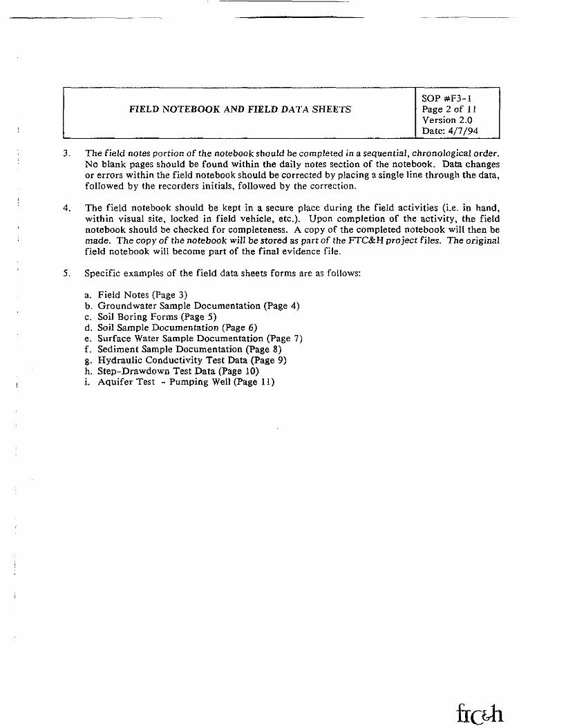
3. The field notes portion of the notebook should be completed in a sequential, chronological order.No blank pages should be found within the daily notes section of the notebook. Data changesor errors within the field notebook should be corrected by placing a single line through the data,followed by the recorders initials, followed by the correction.
4. The field notebook should be kept in a secure place during the field activities (i.e. in hand,within visual site, locked in field vehicle, etc.). Upon completion of the activity, the fieldnotebook should be checked for completeness. A copy of the completed notebook will then bemade. The copy of the notebook will be stored as part of the FTC&H project files. The originalfield notebook will become part of the final evidence file.
5. Specific examples of the field data sheets forms are as follows:
a. Field Notes (Page 3)b. Groundwater Sample Documentation (Page 4)c. Soil Boring Forms (Page 5)d. Soil Sample Documentation (Page 6)e. Surface Water Sample Documentation (Page 7)f. Sediment Sample Documentation (Page 8)g. Hydraulic Conductivity Test Data (Page 9)h. Step-Drawdown Test Data (Page 10)i. Aquifer Test - Pumping Well (Page 11)
FIELD NOTEBOOK AND FIELD DATA SHEETSSOP #F3-iPage 3 of 11Version 2.0Date: 4/7/94
FIELD NOTES
Project Name:_
Project No.:__
Project Site Location:. Date:
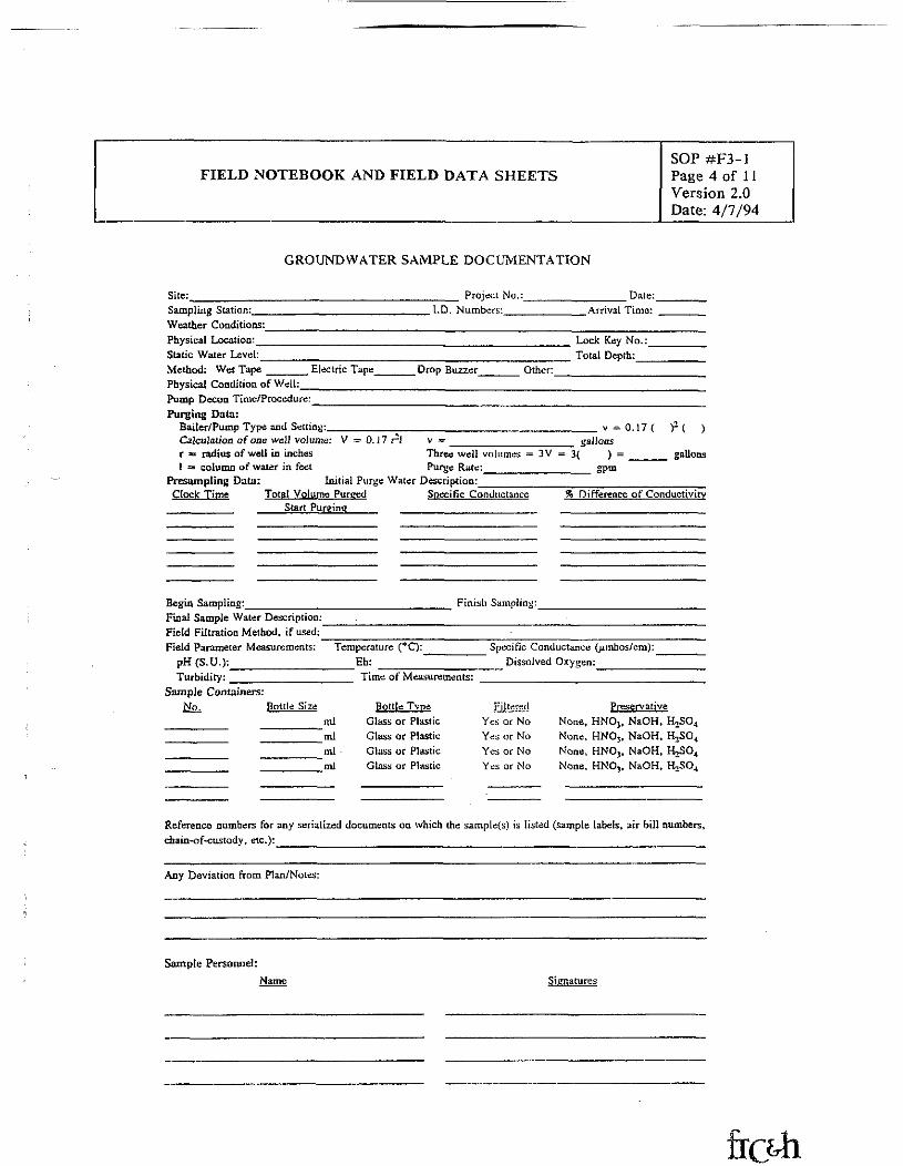
FIELD NOTEBOOK AND FIELD DATA SHEETSSOP #F3-1Page 4 of 11Version 2.0Date: 4/7/94
GROUNDWATER SAMPLE DOCUMENTATION
Site: Project No.:_ Date:Sampling Station:Weather Conditions:Physical Location:Static Water Level:Method: Wet Tape
I.D. Numbers:
Electric Tape Drop Buzzer
Arrival Time:
Lock Key No.:Total Depth:
Other:Physical Condition of Well:____________Pump Decon Time/Procedure:___________Purging Data:
Bailer/Pump Type and Setting:_________Calculation of one well volume: V = 0.17 rlr = radius of well in inches1 =<> column of water in feet
Presampting Data: Initial Purge Water Description:______Clock: Time Total Volume Purged Specific Conductance________ Start Purging___ ________________
v ~ 0.17(v = __________________ gallonsThree well volumes = 3V = 3( ) =Purge Rate:_______________ gpm
gallons
% Difference oF Conductivity
Begin Sampling:__________Final Sample Water Description:Field Filtration Method, if used;Field Parameter Measurements:
pH (S.U.):____________Turbidity: ____________
Finish Sampling:
Temperature (°C):Eh:Time of Measurements:
Specific Conductance (^mhos/cm):Dissolved Oxygen:_______
Sample Containers:Bottle Size
ml'mlml
"ml
Bottle_TypeGlass or PlasticGlass or PlasticGlass or PlasticGlass or Plastic
PreservativeNone, HNOj, NaOH, H2SO4
None, HNO,, NaOH, B_SO4
None, HN03, NaOH, H_>SO4
None, HNO,, NaOH, tUSO4
Reference numbers for any serialized documents on which the sample(s) is listed (sample labels, air bill numbers,chain-of-custody, etc.):_____________________________________________________
Any Deviation from Plan/Notes:
Sample Personnel:Name
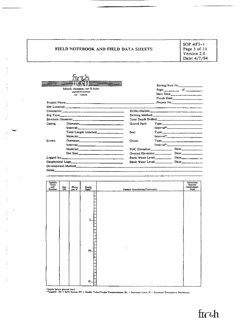
FIELD NOTEBOOK AND FIELD DATA SHEETSSOP #F3-1Page 5 of 1 1Version 2.0Date: 4/7/94
Jfakfishbcck. diotnpson. catr & huber
en nnern 61KJ cnrua
Adi - Liniinc
Project Name:,Site Location:_Contractor__Rig Type:___Borehole Diameter,Casing: Diameter^.
Interval:
Screen:
Total Length Installed.Material:________Diameter________In t e r vat_________Material:_________Slot Size:_________
Logged by:______Geophysical Logs:__Development Method:.Notes:__________
Boring/Well No:Page:______ of.Start Date:______Finish Date:______Project No.:______
Driller/Hel per______Drilling Method:____Total Depth Drilled:__Gravel Pack: Type:.
Seal:
Grout
Interval*--Type:__Interval*:,Type:__Interval*'_______
TOC Elevation:_________ Date:,___ Date-Ground Elevation:.,
Static Water Level,Static Water Levet.
Date:.Date:.
SunplcTypeud
tiuratitrBlow,per 6"
DepthSunpU Due rip t tun/
ScreeningReiulti
InitrumentU.ed
10,
15,
"Depth bslow iround level**Le««nd: S3 =s Split Spoon; ST = Sholby Tub*/Pock*t PinetromaWr; 3L nal Liner; N = SUndard Psnctratioo RsiL.ta
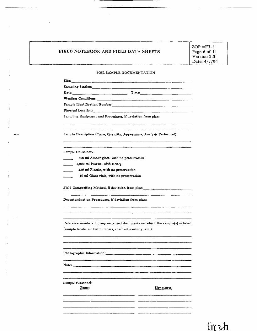
FIELD NOTEBOOK AND FIELD DATA SHEETSSOP#F3-1Page 6 of 11Version 2.0Date: 4/7/94
SOIL SAMPLE DOCUMENTATION
Site:
Sampling Station:_____________________
Date:______________________ Time:.
Weather Conditions:______
Sample Identification Number;_Physical Location:________
Sampling Equipment and Procedures, if deviation from plan:
Sample Description (Type, Quantity, Appearance, Analysis Performed):
Sample Containers:
____ 500 ml Amber glass, with no preservation
___ 1,000 ml Plastic, with HNO3
___ 250 ml Plastic, with no preservation
____ 40 ml Glaas vials, with no preservation
Field Compositing Method, if deviation from plan:_
Decontamination Procedures, if deviation from plan:
Reference numbers for any serialised documents on which the sample (a) ia listed
(sample labels, air bill numbers, chain-of-custody, etc.):
Photographic Information:
Notes:
Sample Personnel;Name: Signatures:

FIELD NOTEBOOK AND FIELD DATA SHEETSSOP #F3-1Page 7 of 11Version 2.0Date: 4/7/94
SURFACE WATER SAMPLE DOCUMENTATION
Site:________________
Sampling Station:________
Date:________ Time:___
Sample Identification Number:,
Physical Location:________
. Weather Conditions:
Sampling Equipment and Procedures, if deviation from plan:
Sample Description (Type, Quantity, Appearance, Analysis Performed):
Sample Containers:__ 1,000 ml Plastic, with no preservation__ 1,000 ml PLutic, with Ullrex__ 1.000 ml PUstic, with H,SO,
500 ml Plastic, wilh NiOH
__ 500 ml Amber glass, with HjSO,__ 40 ml Glass vials, wilh no preservation__ 1,000ml Amber glass, with no preservations__ 1,000 mi glass, wilh HjSO,
Field Filtration Mdhod. if used:_
Decontamination Procedures, if deviation from plan:_
Reference numbers for any serialized documents on which the samplers) is listed (sample labels, air bill numbers, chain-of-
cuslody, etc):
Photographic Information:_______
Final Field Paramelcri Measurements:
Temperature (*C):______________________Specific Conductance (/imhoi/cm):________________
Corrected Specific Conductance (^mhos/cm):________pH (S.U.):__________Time of Measurcmcnls:
Noiea:
Sample Personnel:
Name
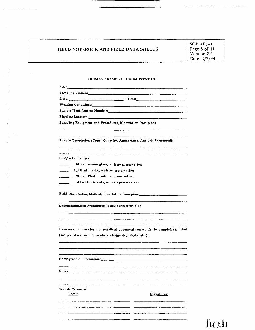
FIELD NOTEBOOK AND FIELD DATA SHEETSSOP#F3-1Page 8 of 11Version 2.0Date: 4/7/94
SEDIMENT SAMPLE DOCUMENTATION
Site:
Sampling Station:,
Date: Time:Weather Conditions:
Sample Identification Number:
Physical Location:________Sampling Equipment and Procedures, if deviation from plan:
Sample Description (Type, Quantity, Appearance, Analysis Performed):
Sample Containers:
_____ 500 ml Amber glass, with no preservation
____ 1,000 ml Plastic, with no preservation____ 250 ml Plastic, with no preservation
40 ml Glass vials, with no preservation
Field Compositing Method, if deviation from plan:_
Decontamination Procedures, if deviation from plan:
Reference numbers for any serialized documents on which the aample(s) is listed
(sample labels, air bill numbers, chain-of-custody, etc.):
Photographic Information:
Notes:
Sample Personnel:Signatures:
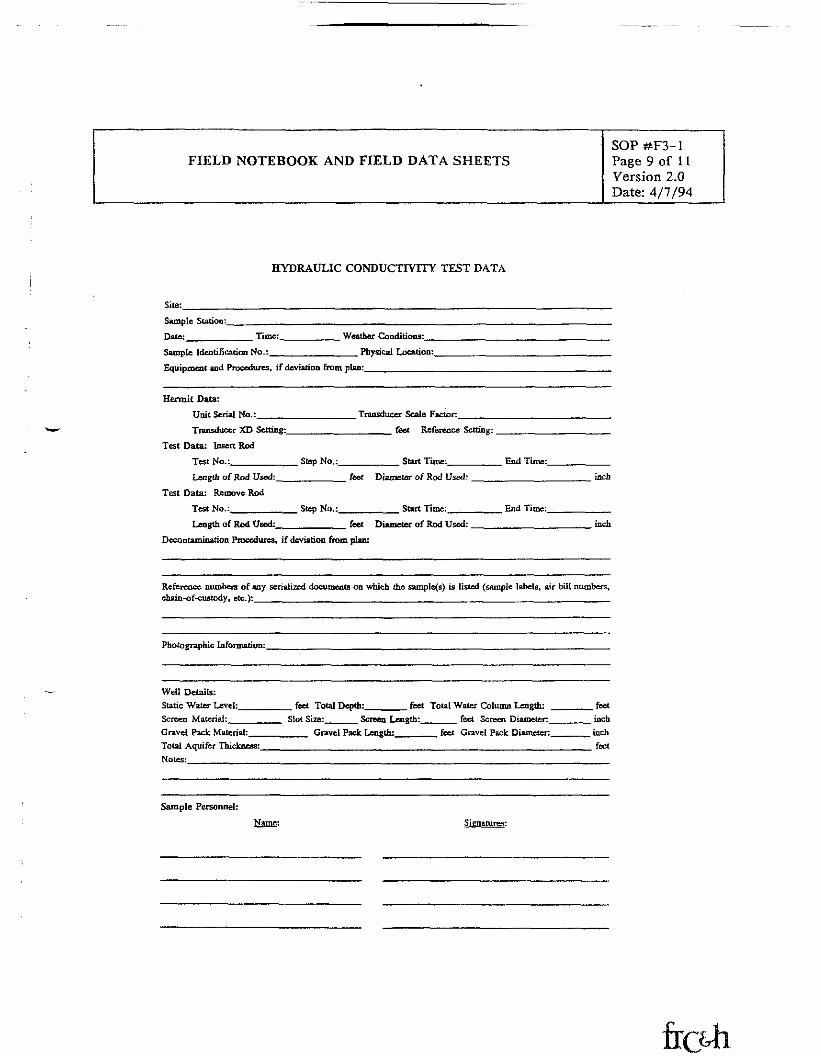
FIELD NOTEBOOK AND FIELD DATA SHEETSSOP#F3-1Page 9 of 11Version 2.0Date: 4/7/94
HYDRAULIC CONDUCTIVITY TEST DATA
Site:______Sample Station;_
Date:______ Time: Weather Conditions:
Sample Identification No.:. . Physical Location:,
Equipment and Procedures, if deviation from plan:..
Hermit Data:Unit Serial No.:_____________
Transducer XD Setting:________
Test Data: Insert RodTest No.:_________ Step No.:_Length of Rod Used:__________
Test Data: Remove RodTest No.:__________ Step No.:.
Transducer Scale Facto r.feet Reference Setting:
Start Time: End Time:
feet Diameter of Rod Used:
Start Time: End Time:
Length of Rod Used:_ feet Diameter of Rod Used:
Decontamination Procedures, if deviation from plan:
inch
inch
Reference numbers of any serialized documents on which the samples) is listed (sample labels, air bill numbers,chain-of-custody, etc.):_________________________________________________________
Photographic Information:,
Well Details:Static Water Level;Screen Material:Gravel Pack: Material:Total Aquifer Thickness:Notes:
feet Total Depth: feet Total Water Column Length:Slot Size: Screen Length: feet Screen Diameter:
Gravel Pack Length: feet Gravel Pack Diameter:
feetinchinchfeet
Sample Personnel:Name:

FIELD NOTEBOOK AND FIELD DATA SHEETSSOP#F3-1Page 10 of 11Version 2.0Date: 4/7/94
STEP-DRAWDOWN TEST DATA
Project Name:_
Date:
Project Task No.
Elevation of Measuring Pointa:_
Well No.: Method of Drawdown Measurement:Static Water Level Elevation:
Method of Pumping Rate Measurement:,
Observer:________________
Remarks/Additional Well Information:
Clock Elapsed PumpingTime Time Rate fQl Hold Read DTW Drawdown fs} Q/S
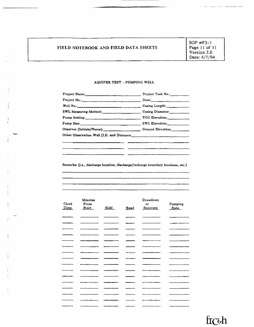
FIELD NOTEBOOK AND FIELD DATA SHEETSSOP #F3-1Page 11 of 11Version 2.0Date: 4/7/94
AQUIFER TEST - PUMPING WELL
Project Name:________________________ Project Task No.:_
Project No.:__________________________ Date:_________
Well No.:____________________________ Casing Length:__
SWL Measuring Method:________________ Casing Diameter:_Pump Setting:________________________ TOG Elevation:_
Pump Sise:___________________________ SWL Elevation:_
Observer (Initials/Name):________________ Ground Elevation:
Other Observation Well (I.D. and Distance:________________
Remarks: (i.e., discharge location, discharge/recharge boundary locations, etc.)
Minutes DrawdownClock From or PumpingTime Start Hold Read Recovery Rate
FISHBECK, THOMPSON, CARR & HUBER, INC,STANDARD OPERATING PROCEDURE
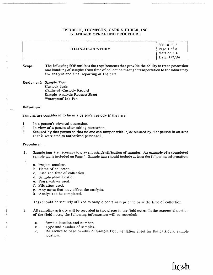
CHAIN-OF-CUSTODYSOP #F3-2Page 1 of 8Version 1.4Date: 4/7/94
Scope:
Equipment:
The following SOP outlines the requirements that provide the ability to trace possessionand handling of samples from time of collection through transportation to the laboratoryfor analysis and final reporting of the data.
Sample TagsCustody SealsChain-of-Custody RecordSample-Analysis Request SheetWaterproof Ink Pen
Definition:
Samples are considered to be in a person's custody if they are:
1. In a person's physical possession.2. In view of a person after taking possession.3. Secured by that person so that no one can tamper with it, or secured by that person in an area
that is restricted to authorized personnel.
Procedure:
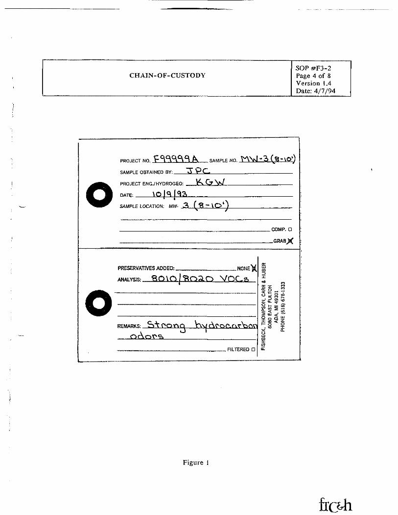
1. Sample tags are necessary to prevent misidentification of samples. An example of a completedsample tag is included on Page 4. Sample tags should include at least the following information:
a. Project number.b. Name of collector.c. Date and time of collection.d. Sample identification.e. Preservatives used.f. Filtration used.g. Any notes that may affect the analysis.h. Analysis to be completed.
Tags should be securely affixed to sample containers prior to or at the time of collection.
2. All sampling activity will be recorded in two places in the field notes. In the sequential portionof the field notes, the following information will be recorded:
a. Sample location and number,b. Type and number of samples.c. Reference to page number of Sample Documentation Sheet for the particular sample
location.
CHAIN-OF-CUSTODYSOP #F3-2Page 2 of 8Version 1.4Date: 4/7/94
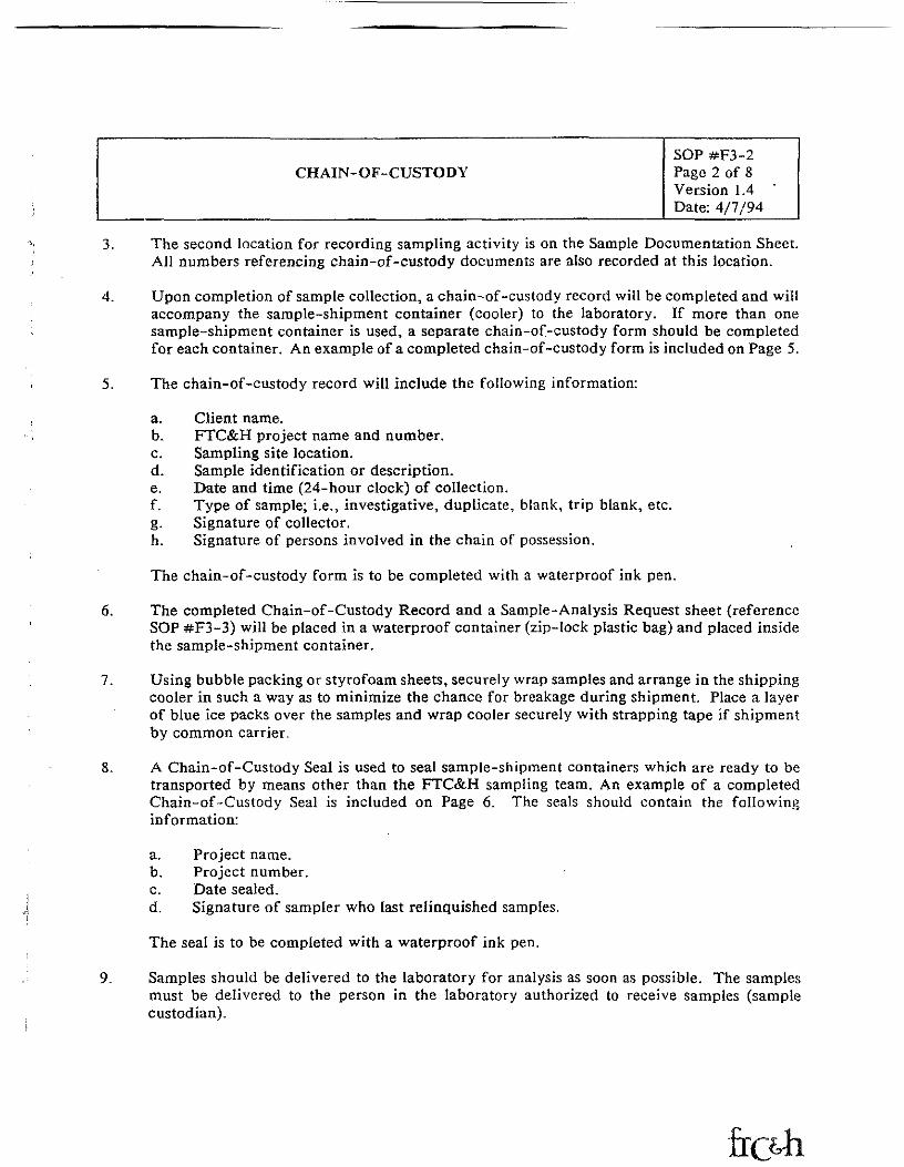
3. The second location for recording sampling activity is on the Sample Documentation Sheet.All numbers referencing chain-of-custody documents are also recorded at this location.
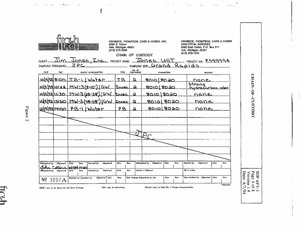
4. Upon completion of sample collection, a chain-of-custody record will be completed and willaccompany the sample-shipment container (cooler) to the laboratory. If more than onesample-shipment container is used, a separate chain-of-custody form should be completedfor each container. An example of a completed chain-of-custody form is included on Page 5.
5. The chain-of-custody record will include the following information:
a. Client name.b, FTC&H project name and number.c. Sampling site location.d. Sample identification or description.e. Date and time (24-hour clock) of collection.f. Type of sample; i.e., investigative, duplicate, blank, trip blank, etc.g. Signature of collector.h. Signature of persons involved in the chain of possession.
The chain-of-custody form is to be completed with a waterproof ink pen.
6. The completed Chain-of-Custody Record and a Sample-Analysis Request sheet (referenceSOP #F3-3) will be placed in a waterproof container (zip-lock plastic bag) and placed insidethe sample-shipment container.
7. Using bubble packing or styrofoam sheets, securely wrap samples and arrange in the shippingcooler in such a way as to minimize the chance for breakage during shipment. Place a layerof blue ice packs over the samples and wrap cooler securely with strapping tape if shipmentby common carrier.
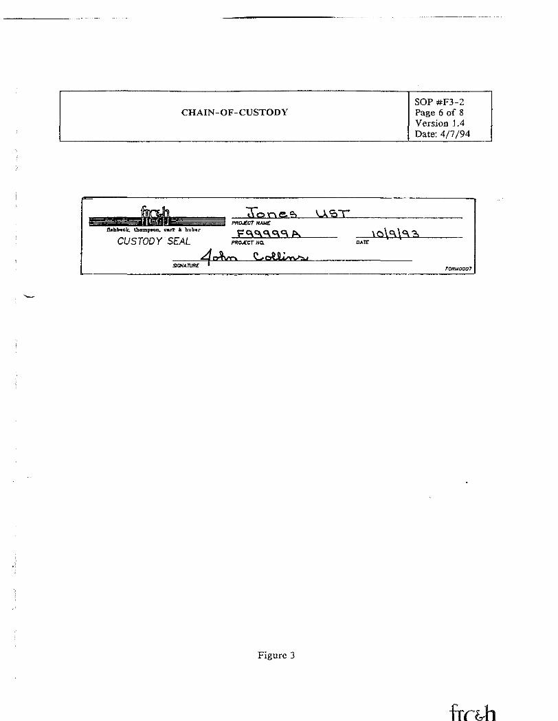
8. A Chain-of-Custody Seal is used to seal sample-shipment containers which are ready to betransported by means other than the FTC&H sampling team. An example of a completedChain-of-Custody Seal is included on Page 6. The seals should contain the followinginformation:
a. Project name.b. Project number.c. Date sealed.d. Signature of sampler who last relinquished samples.
The seal is to be completed with a waterproof ink pen.
9- Samples should be delivered to the laboratory for analysis as soon as possible. The samplesmust be delivered to the person in the laboratory authorized to receive samples (samplecustodian).
CHAIN-OF-CUSTODYSOP #F3-2Page 3 of 8Version 1.4Date: 4/7/94
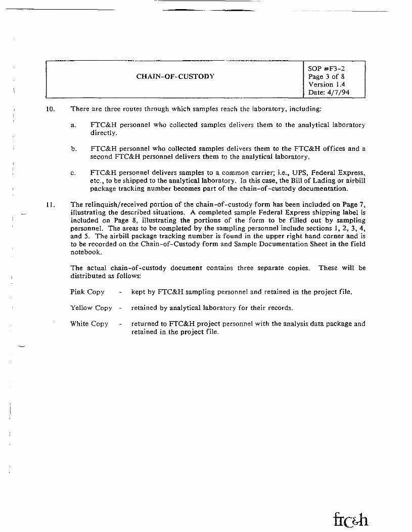
10. There are three routes through which samples reach the laboratory, including:
a. FTC&H personnel who collected samples delivers them to the analytical laboratorydirectly.
b. FTC&H personnel who collected samples delivers them to the FTC&H offices and asecond FTC&H personnel delivers them to the analytical laboratory.
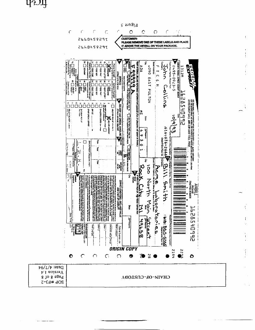
c. FTC&H personnel delivers samples to a common carrier; i.e., UPS, Federal Express,etc., to be shipped to the analytical laboratory. In this case, the Bill of Lading or airbillpackage tracking number becomes part of the chain-of-custody documentation.
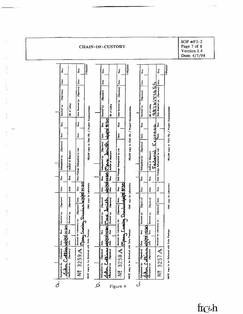
II. The relinquish/received portion of the chain-of-custody form has been included on Page 7,illustrating the described situations. A completed sample Federal Express shipping label isincluded on Page 8, illustrating the portions of the form to be filled out by samplingpersonnel. The areas to be completed by the sampling personnel include sections 1, 2, 3, 4,and 5. The airbill package tracking number is found in the upper right hand corner and isto be recorded on the Chain-of-Custody form and Sample Documentation Sheet in the fieldnotebook.
The actual chain-of-custody document contains three separate copies. These will bedistributed as follows:
Pink Copy - kept by FTC&H sampling personnel and retained in the project file.
Yellow Copy - retained by analytical laboratory for their records.
White Copy - returned to FTC&H project personnel with the analysis data package andretained in the project file.
CHAIN-OF-CUSTODYSOP #F3-2Page 4 of 8Version 1.4Date: 4/7/94
PRO IFCT NO. f" S^HH " K SAMP1 P Nfl TAVJ " 3 (J3 - VOVj
SAMPI F OHTAINPn RY: "3" P C.
O PRniFnr FNP, /HvnRnr.EO- Kv Gr \N/
DATF^ \O j^ [^S
SAMPLF LOCATION: MW- S (^-\O*)\ /
COM P. n
PRESERVATIVES ADDED: NONP^(
ANALYSIS SO\n 1 ^OSLC^) VOC-S
REMARKS: S\ oonn KM f\corrfv^rtpOC\0<C^
Fli TFRFH n FISH
BEC
K, T
HO
MPS
ON
. C
ARR
& H
UBE
R60
80 E
AST
FULT
ON
ADA,
Ml
4930
1PH
ONE
(61
6) 6
76-1
333
Figure I
CTQd-i(D
to
FISHBECK, THOMPSON, CARR & HUBER, INC.6090 E. FultonAda, Michigan 46301(616) 676-2666
CHAIN OF CUSTODYCLIENT-. ——v\\rf\ OQne.^. t"Hr\c-. PROJECT NAME-. .SAMPLING PERSONNEL: <T P Cr____________________ SAMPLING SITE:.
FISHBECK, THOMPSON, CARR & HUBERANALYTICAL SERVICES6080 East Fulton. P.O. Box 211Ada. Michigan 49301(616) 676-1333
NO.:
WJirc copy lo bt R*lum,d -JIA Data Pa PSHK copy te totMolory JtUOW copy '" / Projtcl DeeunnnloKe
CN
-OF-C
UST
OD
Y
13 W» O00 ,_,n> "..,Ui ff
4x oo
CHAIN-OF-CUSTODYSOP #F3-2Page 6 of 8Version 1.4Date: 4/7/94
PROMCT NAIICflihbcck. thompton. carr Jt tiubcr
CUSTODY'SEAL PROJKT HO.
Figure 3
SOP #F3-2CHAIN-OF-CUSTODY Page 7 of S
Version 1.4Date: 4/7/94
——
——
- ,cli
1
*
1^
Iq-
^
J
Q
•?ji
15.
•4
3- -'"*
*
^
1
*Q
*
i
A
* ca r
"1v a§"3
£.
1J
J- ^
'"c^•* 1* _>i 1
N^
Ob
I
<aai
S
1i£•a
"iiI
Q
•
I
i«.
jflc
1jja
1
j[>"—H•a41J
"Ia:
.?£
1*
1
11i•*%
a
313j;tc*?
"SQ
O
— c* n« *"
1v aa 1
| '
i. -;"" t
? 'k 12 *7* «-
i i"5 C
* C
<JCT)LOOJro01
2
§o35""
|_o! ——
a«.
^iX
CTJ•*C5X
o
__
_^«_
J
1_j ————
1
1
ll
"oa
l*
~
V
D
&fbi
'4
&
a
_,.3
|
!o
<• J?1 flC
fl^3 H
HijX.
i 3i <Ivo: W
Q„ r
1
M*^i I'j^uji1'. ^js -jA
j.j^$*• /5 <
i <4I"S
*1s
»
"
1?•*
K
jjo
14¥4
*
1——
Ui
1•
£*-^4
J
«
1
a
|
1
t
ijo
,.^'aa
|J
1ff?o.
i<
£ ob"5i 3o "3--. t1 -T
1 =
* J
113 *-5 :
* f* &
<ICOLDCXIooOl~y
Qad»SIt
1\ ~a
1£X
CT>1Ca
j
*
....
1
S3 -
* o"~
t xCL
i->
*a.
— Tio£"S•o
|*(c•a —.2>\&•™teS
4,s
1*Ji,B.
|
(c
it
a
-^|j
I
^
|
a:
'4
|
.
a
1
x
|ec
1 2f
-. •'fio j
1 1J** •— Cj
,
^ g
"3 jp-E t•K~
if
-£
J* J>1 r
i <*"
Jij*c'ii^
& irA- *•S «-s-C•». •» U"3
4
|
^%
S
1x
jtc
1
————
'.
1
*
^>-
1
"S--a
(C
*B
O
S,S.
iioc
a.
£ —j;o
2
|
15<c
g1
"80.
o
•4
5
J
I
^
3|-a
cc
<Jr—tnCNJCO
Ol2!
aao3Su_
|'oiE3a
1a.X
C•o•*ca
I
O
1
1a2~*>i0.
le1
a
80.
'HoSi•fl
|EC
X0
>«8-t;1
Figure 4
O OCUSTOMER:PLEASE REMOVE ONE OF THESE LABELS AND PLACEIT ABOVE THE AIRBILL ON YOUR PACKAGE.
O C o
8 jo AaoxsnD -HO -NI VHD
FISHBECK, THOMPSON, CARR & HUBER, INC,STANDARD OPERATING PROCEDURE
GROUNDWATER SAMPLING - GENERAL OVERVIEWSOP#F4-1Page 1 of 3Version 1.3Date; 4/7/94
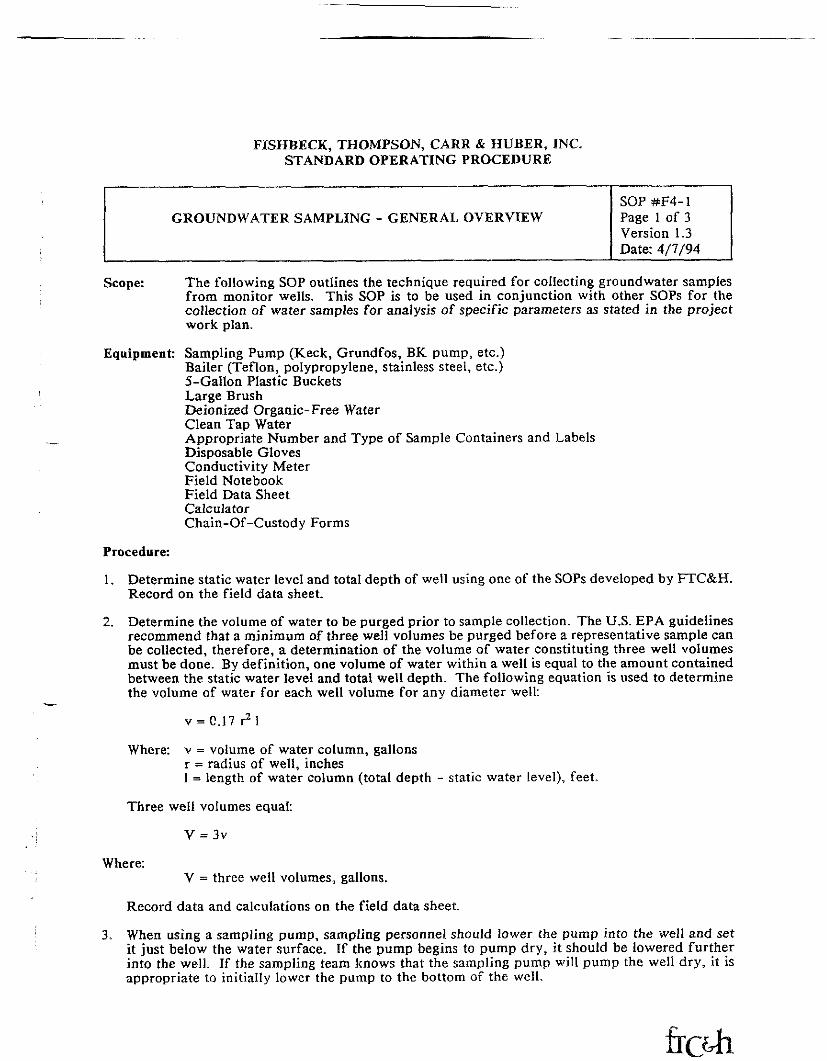
Scope: The following SOP outlines the technique required for collecting groundwater samplesfrom monitor wells. This SOP is to be used in conjunction with other SOPs for thecollection of water samples for analysis of specific parameters as stated in the projectwork plan.
Equipment Sampling Pump (Keck, Grundfos, BK pump, etc.)Bailer (Teflon, polypropylene, stainless steel, etc.)5-Gallon Plastic BucketsLarge BrushDeionized Organic-Free WaterClean Tap WaterAppropriate Number and Type of Sample Containers and LabelsDisposable GlovesConductivity MeterField NotebookField Data SheetCalculatorChain-Of-Custody Forms
Procedure:
1. Determine static water level and total depth of well using one of the SOPs developed by FTC&H.Record on the field data sheet.
2. Determine the volume of water to be purged prior to sample collection. The U.S. EPA guidelinesrecommend that a minimum of three well volumes be purged before a representative sample canbe collected, therefore, a determination of the volume of water constituting three well volumesmust be done. By definition, one volume of water within a well is equal to the amount containedbetween the static water level and total well depth. The following equation is used to determinethe volume of water for each well volume for any diameter well:
v = C.I7 r2!
Where: v = volume of water column, gallonsr = radius of well, inches1 = length of water column (total depth - static water level), feet.
Three well volumes equal:
V = 3v
Where:V = three well volumes, gallons.
Record data and calculations on the field data sheet.
When using a sampling pump, sampling personnel should lower the pump into the well and setit just below the water surface. If the pump begins to pump dry, it should be lowered furtherinto the well. If the sampling team knows that the sampling pump will pump the well dry, it isappropriate to initially lower the pump to the bottom of the well.
GROUNDWATER SAMPLING - GENERAL OVERVIEWSOP#F4-1Page 2 of 3Version 1.3Date: 4/7/94
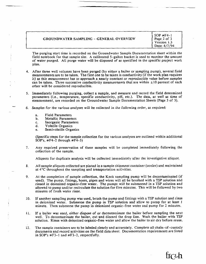
The purging start time is recorded on the Groundwater Sample Documentation sheet within thefield notebook for that sample site. A calibrated 5-gallon bucket is used to monitor the amountof water purged. All purge water will be disposed of as specified in the specific project workplan.
4. After three well volumes have been purged (by either a bailer or sampling pump), several fieldmeasurements are to be taken. The first one to be taken is conductivity (if the work plan requiresit) as this measurement has to approach a nearly constant or reproducible value before samplescan be taken. Three successive conductivity measurements that are within ±10 percent of eachother will be considered reproducible.
5. Immediately following purging, collect a sample, and measure and record the field determinedparameters (i.e., temperature, specific conductivity, pH, etc.). The data, as well as time ofmeasurement, are recorded on the Groundwater Sample Documentation Sheets (Page 3 of 3).
6. Samples for the various analyses will be collected in the following order, as required:
a. Field Parametersb. Metallic Parametersc. Inorganic Parametersd. Volatile Organicse. Semivolatile Organics
(Specific steps for the sample collection for the various analyses are outlined within additionalSOP's, #F4-2 through #F4-5)
7. Any required preservation of these samples will be completed immediately following thecollection of the sample.
Aliquots for duplicate analysis will be collected immediately after the investigative aliquot.
8. All sample aliquots collected are placed in a sample shipment container (cooler) and maintainedat 4°C throughout the sampling and transportation activities.
9. At the completion of sample collection, the Keck sampling pump will be decontaminated (ifused). The pump, fittings, hoses, pipes and wires will all be brushed with a TSP solution andrinsed in deionized organic-free water. The pumps will be submersed in a TSP solution andallowed to pump and/or recirculate the solution for five minutes. This will be followed by twominutes of fresh water rinse.
10. If another sampling pump was used, brush the pump and fittings with a TSP solution and rinsein deionized water. Submerse the pump in TSP solution and allow to pump for at least 1minute. Then submerse the pump in deionized organic-free water and pump for 2 minutes.
11. If a bailer was used, either dispose of or decontaminate the bailer before sampling the nextwell. To decontaminate the bailer, cut and discard the drop line. Wash the bailer with TSPsolution. Rinse with deionized organic-free water and allow the bailer to air dry before reuse.
12. The sample containers are to be labeled clearly and accurately. Complete all chain-of--custodydocuments and record activities on the field data sheet. Documentation requirements are listedin SOP's #F3-1 and #F3-2, respectfully.

GROUNDWATER SAMPLING - GENERAL OVERVIEWSOP#F4-IPage 3 of 3Version 1.3Date: 4/7/94
Site:
GROUNDWATER SAMPLE DOCUMENTATION
Project No.: Date:Sampling Station: I.D. Numbers: Arrival Time:Weather Conditions:Physical Location:Static Water Level:Method: Wet Tape
Lock Key No.:Total Depth:
Electric Tape Drop Buzzer Other:Physical Condition of Well:Pump DecoD Time/Procedure:Purging Data:
Bailer/Pump Type and Setting:Calculation of one well volume: V = 0.17 r2!r =i radius of well in inches1 s= column of water in feet
Presampling Data: Initial Purge Water Description: ______ClockLTjme Total Volume Purged Specific Conductance_______ Start Purging ___ ________________
________________________ v = 0.17 (v = _______________ gallonsThree well volumes = 3V = 3( ) = ___Purge Rate:_____________ gpm
gallons
% Difference of Conductivity
Begin Sampling:__________Final Sample Water Description:Field Filtration Method, if used:_Field Parameter Measurements:
pH (S.U.):____________Turbidity: ____________
Finish Sampling:_
Temperature (°C):Eh:
Specific Conductance (/tmhos/cm):Dissolved Oxygen: __
Time of Measurements:Sample Containers:
Bottle Sizeml
"ml
ml
Bottje,,T.KpeGlass or PlasticGlass or PlasticGlass or PlasticGlass or Plastic
PreservativeNone, HN03, NaOH.None, HNO3, NaOH, H2SO4
None, HNO3, NaOH,Yes or No None, HNO3, NaOH, It
Reference numbers for any serialized documents on which the samplers) is listed (sample labels, air bill numbers,chain-of-custody, etc.):
Any Deviation from Plan/Notes:
Sample Personnel:Name
FISHBECK, THOMPSON, CARR & HUBER, INC.STANDARD OPERATING PROCEDURES
COLLECTION OF GROUNDWATER SAMPLE ALIQUOTFOR VOLATILE ORGANIC COMPOUNDS
SOP #F4-4Page 1 of 2Version 1.4Date: 11/18/93
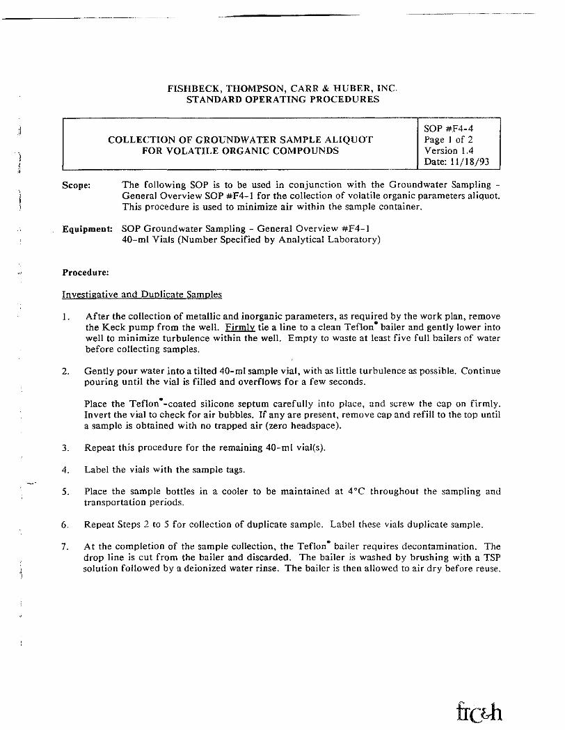
Scope: The following SOP is to be used in conjunction with the Groundwater Sampling -General Overview SOP #F4-1 for the collection of volatile organic parameters aliquot.This procedure is used to minimize air within the sample container.
Equipment: SOP Groundwater Sampling - General Overview #F4-140-mI Vials (Number Specified by Analytical Laboratory)
Procedure:
Investigative and Duplicate Samples
1. After the collection of metallic and inorganic parameters, as required by the work plan, removethe Keck pump from the well. Firmly tie a line to a clean Teflon* bailer and gently lower intowell to minimize turbulence within the well. Empty to waste at least five full bailers of waterbefore collecting samples.
2. Gently pour water into a tilted 40-mI sample vial, with as little turbulence as possible. Continuepouring until the vial is filled and overflows for a few seconds.
Place the Teflon -coated silicone septum carefully into place, and screw the cap on firmly.Invert the vial to check for air bubbles. If any are present, remove cap and refill to the top untila sample is obtained with no trapped air (zero headspace).
3. Repeat this procedure for the remaining 40-mI vial(s).
4. Label the vials with the sample tags.
5. Place the sample bottles in a cooler to be maintained at 4°C throughout the sampling andtransportation periods.
6. Repeat Steps 2 to 5 for collection of duplicate sample. Label these vials duplicate sample.
7. At the completion of the sample collection, the Teflon* bailer requires decontamination. Thedrop line is cut from the bailer and discarded. The bailer is washed by brushing with a TSPsolution followed by a deionized water rinse. The bailer is then allowed to air dry before reuse.
SOP #F4-4Page 2 of 2Version 1.4Date: 11/18/93
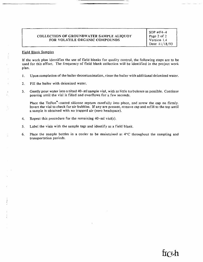
Field Blank Samples
If the work plan identifies the use of field blanks for quality control, the following steps are to beused for this effort. The frequency of field blank collection will be identified in the project workplan.
1. Upon completion of the bailer decontamination, rinse the bailer with additional deionized water.
2. Fill the bailer with deionized water.
3. Gently pour water into a tilted 40-ml sample vial, with as little turbulence as possible. Continuepouring until the vial is filled and overflows for a few seconds.
Place the Teflon*-coated silicone septum carefully into place, and screw the cap on firmly.Invert the vial to check for air bubbles. If any are present, remove cap and refill to the top untila sample is obtained with no trapped air (zero headspace).
4. Repeat this procedure for the remaining 40-ml vial(s).
5. Label the vials with the sample tags and identify as a field blank.
6. Place the sample bottles in a cooler to be maintained at 4°C throughout the sampling andtransportation periods.
FISHBECK, THOMPSON, CARR & HUBER, INC.STANDARD OPERATING PROCEDURE
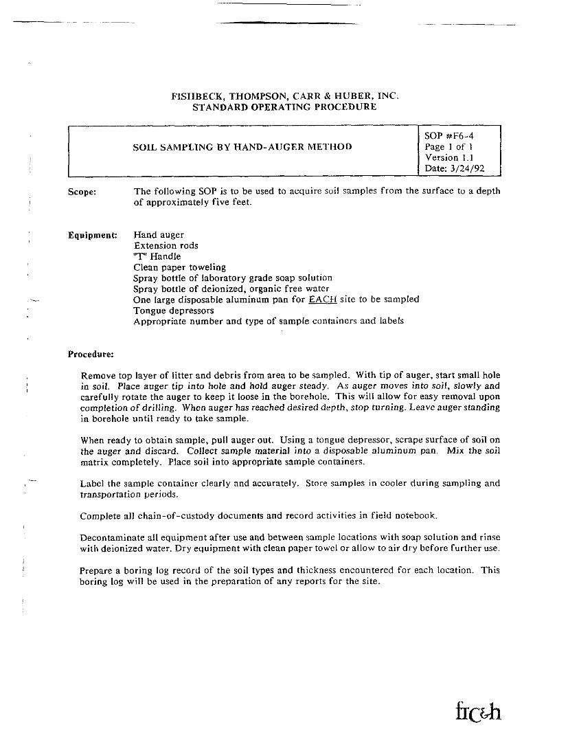
SOIL SAMPLING BY HAND-AUGER METHODSOP #F6-4Page 1 of IVersion 1.1Date: 3/24/92
Scope: The following SOP is to be used to acquire soil samples from the surface to a depthof approximately five feet.
Equipment: Hand augerExtension rods"T" HandleClean paper towelingSpray bottle of laboratory grade soap solutionSpray bottle of deionized, organic free waterOne large disposable aluminum pan for EACH site to be sampledTongue depressorsAppropriate number and type of sample containers and labels
Procedure:
Remove top layer of litter and debris from area to be sampled. With tip of auger, start small holein soil. Place auger tip into hole and hold auger steady. As auger moves into soil, slowly andcarefully rotate the auger to keep it loose in the borehole. This will allow for easy removal uponcompletion of drilling. When auger has reached desired depth, stop turning. Leave auger standingin borehole until ready to take sample.
When ready to obtain sample, pull auger out. Using a tongue depressor, scrape surface of soil onthe auger and discard. Collect sample material into a disposable aluminum pan. Mix the soilmatrix completely. Place soil into appropriate sample containers.
Label the sample container clearly and accurately. Store samples in cooler during sampling andtransportation periods.
Complete all chain-of-custody documents and record activities in field notebook.
Decontaminate all equipment after use and between sample locations with soap solution and rinsewith deionized water. Dry equipment with clean paper towel or allow to air dry before further use.
Prepare a boring log record of the soil types and thickness encountered for each location. Thisboring log will be used in the preparation of any reports for the site.
2
STEARNS DRILLING
Dutton, Ml 616/698-7770Howell, Mi 517/546-2470
1 rt L~ M~ ' -^ -~* LAX / *
LOG OF TEST BORING NO. JU^
/ 7Sheet / of *—
'Prnjeg PTC//
Location \JUQ. \\Af\An M<
//-')7-^<Date Completed V / / ->
/I f . /T
<vew r.hifif Axr /^Cj^lL^A.nrill Rig rlilPjI/s D ~1^
Rnring Methnri *i^7\ nO i
t^le Plugged With JCPV^"^^* ^>'OyVV
(P'Pr— O folAck D»t-iGROUNDWATER: <9f2rFnrnuntfirfid fa) O O n ft.After nompletinn ft.After , hrs. ft.
Boring Caved at ft.
MONITOR WELL DATA:Pipe/Type
Length•Above ftroundCap
~ *-ee»n/Type. Si>R
Slot
Set @Backfilled
Rentonite Seal
Grout/Typeriftpth
Materials Cleaned
Development
^ "•.
REMARKS:
LEGEND:BlowCount/Blows per 6"
w/140# hammer x 30" dropSS - 2" Split Spoon SamplerLS - Brass Liner SampleST - Shelby Tuba SampleSNR - Sample not recovered
SampleType REC
BlowCount
DepltiIn
Feat
5 -
10-
lb —
25-
30 —
—
•~
_
-
—
_
—
„
_^^^
•
—
—~„
—
-—„_^
—^
—
-—
J~I
SOIL DESCRIPTION
*- o
Dutton, Ml 616/698-7770Howeil, Ml 517/546-2470
3^~ COC"-?- ~1.loh No / J> O ii J / '
LOG OF TEST BORING NO, TVt/~ /
Shfifit cA of Ov
Project r-TC H
1 nratjnn iP(_r p, A y\ X] f\ 1 • ) .
Hatfi CnrnplfitPri / a* / c* 3
5 A nnC A S P^ 'Crew Chiefnrill RigRnring MflthnH
RPIngrjPriWith \ /
GROUNDWATER:Encountered @ ft.After cnmplRttnn ft.After hrs. ftSsspago ftRnring Cavpri at ft
MONITOR WELL DATA:Pipe/Type
1 engthAhnvP Rrntmri
Cap
S^rPfin/TypoSi7P
Set fS)BarlrfillPri
Sentonitft Sealfirnnt/Typp
DepthPrntfiotivw Casing
Materials Cleaned
Develnprnsnt
REMARKS!a"$
LEGEND:BlowCount/Blows per 6"
w/140# hammer x 30" dropSS - 2" Split Spoon SamplerLS - Brass Liner SampleST - Shelbv Tube SampleSNR - Sample not recovered
SampleType REG
BlowCount In
Feet
J»^'qtfU.
*&<yv~
+*/f#&*
a&Q.^w
25-
1f\JU ^^
—
"™
f—
—
«tH.
-
i
17 <c , ^pu?tAjn OA
O *S A.vi TCJ^J n O/A
— — —— — — —^^f^t/Y}\yf-/0 i*Ji 1~
SOIL DESCRIPTION
0 I CMnilNI ) UrilL.LJHUa
Dutton, Ml 616/698-7770Howell, Ml 517/546-2470
LOG OF TEST BORING NO. ~*W5L—
ShflBt \ of *t. /
Project £"v{- H^r/r^Crny Vo \ C-P
(
1 nration /-X-C HxA n/4 /f i
Dates rnmplptpd a£s / —
Crew nhiflfA.f r/ ^J?ll4&<£nnii niG rloN&J> 5*1Boring Method y Tfi iO"
"?>j*"Z.v*r /QPr-l ft" 'Hol pl 'GROUNDWATER:Fnrnnntprpri (S) 3>^ ^
After cnmplRtion ft.After hrs. ft.Seepage ft.Boring Caved at ft.
MONITOR WELL DATA:Pipe/Type
1 ffnrjthAhnve firound
Cap
Screen/Type
- SlntSpt (a>
Barkfilled
Rentonite Sealfirn ut /Type
OppthPrntertive Casing
Materials Cleaned
REMARKS!-i
LEGEND:BlowCount/Blows per 6"
w/140# hammer x 30" dropSS - 2" Split Spoon SamplerLS - Brass Liner SampleST- Shelbv Tube SampleSNR - Sample not recovered
iiampli:Type
-
RECEllawCount III
Foot
10
15
20
25
SOIL DESCRIPTION
^^70
J
STEARNS DRILLING
'utton, Ml 616/698-7770Fenton, Ml 810/750-5141
LOG OF TEST BORING NO.
Jheet ___L_.... of. ....L
Project <"
Location
pate Completed
Crewprill Rig J.OCoring Method
15
GROUNDWATER:
\fter completion __After _____ hrs.Seepage _____Soring Caved at _
MONITOR WELL DATA:Pipe/Type ____________
LengthAbove GroundCap ______
^creen/Type:e __
Tsiot __Set @_Backfilled
Bentonite SealSlrout/Type _
Depth ___Protective Casing .Materials Cleaned
Development __
REMARKS:
LEGEND:BlowCounf Blows par 6"
w/140# hammer x 30" dropSS - 2™ Split Spoon SamplerLS - Brass Liner SampleST - Shelby Tube SampleSNR - Sample not recovered
S*mploType REC
BlowCount
v-z
20
25
30
rS
STEARNS DRILLING
)utton, Ml 616/698-7770Fenton, Ml 810/750-5141
LOG OF TEST BORING NO. QS&-1^_
ShPet I nf I
Project FHC K! pl^c-k-f) Vnirc
l,nnr.atinn CX-T n/^v-^VN \*\ \
n~-4i-,G<Oatfi Completed ' O' f J
e, \ HlC1/0 I.Q 1 1 C-\ T i v. if-*| (c, n«ADriM Rig ^1? fe-5?lgoring Mfithnri *-j ->'% HoA"
(H6rrj Plugged With G^T-^^V^ t>!ut'f)'i*^5~3 PT 5^f\ — O -\OpStnl /
GROUNDWATER:Encountered @ ___________ 25_ ft.AffRr comp'flt!"" ftAfter hrs. ft.^f>ppaqp ft.
pnring C.avetct at ft.
MONITOR WELL DATA:Pipe/Type
1 fingthAbove GroundCap
?P. "Slot
Sfit (a)Ra lrfillpH
RpntnnitR Ssal
tirout/TypeDepth
ProtectivR CasingK/lat<-»nnlet ClftapeH
n*?vRlnpmRnt
REMARKS:
LEGEND:BlowCount/Blows per 6"
w/14Q# hammer x 30" dropSS - 2" Split Spoon SamplerLS ~ Brass Linar SampleST - Shelby Tube SampleSNR - Sample not recovered
SamplaType
SSf-n ^' — '
•55
<TS3 j
REC
75~.
7^
7S
BlowCount
3-77V^
t/~(*ti-fo
DepthIn
Feet
_#•*!
-**7-IB*2
-o-
-« l
JW^UV' '
25-
30-
__
-
-
-
-
—
-
^~
^m
—
„
_
^
•~
——
™,
—
SOIL DESCRIPTION
5/^TVAy lirot^jrx C-iAV '4-C1rAv/^
foxuooo Sc,n^*-^TAv^
—— - .* _^ ____ ________ — -—
*ol7Jcoi> z^| |J_
3$i*r &*&>'&,
• H
TW
——
_
-
——
~
_
—
_
*^
•^
—
~
«*.
J___
__
—
—— ,
-
——
__
—
TTEARNS DRILLING
button, Ml 616/698-7770Fenton, Ml 810/750-5141
-7Job No. 7 5 ^
'_OG OF TEST BORING NO.
/ of... '
^TC A/
Location
Completed . ""' i 5_
Drill Rig B-5^Method
HgT^PluggedWith
\JGROUNDWATER:Encountered @__<Mter completion __After _____ hrs.
Soring Caved at
MONITOR WELL DATA:Pipe/Type ________
Length ________
Cap
Slot
Backfilled
pentonite SealGrout/Type _
Depth ___Protective Casing
Development
REMARKS:
LEGEND:BlowCounf Blows per 6"
w/140# hammer x 30" dropSS- 2" Split Spoon SamplerLS - Brass Liner SamplsST- Shelby Tuba SampleSNR - Sample not recovered
SampleTypfl
35
75
75
BlowCount
3-4
sr-«
DopihIn
Foot
15
25-
SOIL DESCRIPTION
O
iTEARNS DRILLING
uutton, Ml 616/698-7770Fenton, Ml 810/750-5141
Job No. ft-5857- 7.OG OF TEST BORING NO.
Sheet / of __-L_
^reject
vocation
Date Completed
Crew Chief..Drill RigBoring Method
nffr-o
GROUNDWATER:.Encountered @__After completion _After _____ hrs.ISeepage _____iBoring Caved at _
ft.ft.ft.ft.ft.
MONITOR WELL DATA:Pipe/Type
LengthAbove GroundCap ______
-^en/Type
Slot __Set @ __Backfilled
Bentonite Sea]Grout/Type _
Depth ___> Protective Casing .
,t Materials CleanedDevelopment __
REMARKS: _.
LEGEND:BlowCount/Blows per 6"
w/140# hammer x 30" dropSS - 2" Split Spoon SamplerLS - Brass Liner SampleST - Shalby Tuba SampleSNR - Sample not recovered
Sam pis
A
55
REGBlow
•-Count
199
DnpthIn
Faet
Q
15
25
30
SOIL DESCRIPTION
<B>)«c l<
U
FTC&H ANALYTICAL SERVICESSAMPLE RESULT FORM
Sample ID TW-1(60-65 ' }
Lab ID 950700503
Matrix water
Dilution Factor
COMPOUND
1,1,l~Trichloroethane1,1,2,2-Tetrachloroethane1,1,2-Trichloroethane1,1-Dichloroethane1,1-Dichloroethene1, 2-Dichloroethane1, 2-Dichlorobenzene1,2-Dichloropropane1, 3~Dichlorobenzene1,4-Dichlorobenzene2-Chloroethylvinyl etherBenzeneBromodlchloromethaneBromomethanecis-l,2-Dichloroethenecis-l,3-DichloropropeneChlorobenzeneCarbon TetrachlorideBromoformChloroformChloroethaneChloromethaneDlbromochloromethaneEthyl BenzeneMethylene ChlorideTetrachloroethenetrans-1,2-DichloroetheneTrichloroetheneTrichlorofluoromethaneTolueneVinyl ChlorideXylenes
Page No.
QC Report
Units
Sample Da
Analysis
DL
1.01,01.01.01.01.01.01.01.01.01.01.01.01.01.01.01.01.01.01.01,01.01.01.01.01.01.01.01.01.01.01.0
0049508016
UCf/1
te 07/26/95
Date 08/04/95
RESULTS
1.0 U1.0 U1.0 U1.0 U1.0 U1.0 U1.0 U1.0 U1.0 U1.0 U1.0 U1.0 U1.0 U1.0 U0.4 J1.0 U1.0 U1.0 U1.0 U1.0 U1.0 U1.0 U1.0 U1.0 U1.0 U1.0 U1.0 U4.4 C1.0 U1.0 U1.0 U1.0 U
COMMENTS:
FTC&H ANALYTICAL SERVICESSAMPLE RESULT FORM
Sample ID TW-2f60-65')
Lab ID 950700504_____
Matrix water
Dilution Factor
COMPOUND
1,1,1-Trichloroethane1,1,2,2-Tetrachloroethane1,1,2-Trichloroethane1,1-Dichloroethane1.1-Dichloroethene1.2-Dichloroethane1,2-Dichlorobenzene1.2-Dichloropropane1.3-Dichlorobenzene1.4-Dichlorobenzene2-Chloroethylvinyl etherBenzeneBromodlchloromethaneBromomethanecis-l,2-Dichloroethenecis-1,3-DichloropropeneChlorobenzeneCarbon TetrachlorideBromoformChloroformChloroethaneChloromethaneDlbromochloromethaneEthyl BenzeneMethylene ChlorideTetrachloroethenetrans-l,2-DichloroetheneTrichloroetheneTrichlorofluoromethaneTolueneVinyl ChlorideXylenes
Paae No, 005OC Report 9508016
Units UQ/1
Sample Date
Analysis Date
DL
1.01.01.01.01.01.01.01.01.01.01.01.01.01.01.01.01.01.01.01.01.01.01.01.01.01.01.01.01.01.01.01.0
__-
07/27/95
08/04/95
RESULTS
1.0 U1.0 U1.0 U1.0 U1.0 U1.0 U1.0 U1.0 U1.0 U1.0 U1.0 U1.0 U1.0 U1.0 U1.0 U1.0 U1.0 U1.0 U1.0 U1.0 U1.0 U1.0 U1.0 U1.0 U1.0 U1.0 U1.0 U1.6 C1.0 U1.0 U1.0 U1.0 U
COMMENTS

FTC&H ANALYTICAL SERVICESSAMPLE RESULT FORM
Sample ID FB-1
Lab ID 950700505
Matrix water
Dilution Factor 1
COMPOUND
1,1, 1-Trichloroethane1,1,2, 2-Tetrachloroethane1,1,2 -Trichloroethane1 , 1-Dichloroethane1, 1-Dichloroethene1 , 2-Dichloroethane1, 2-Dichlorobenzene1 , 2-Dichloropropane1, 3-Dichlorobenzene1 , 4-Dichlorobenzene2-Chloroethylvinyl etherBenzeneBromodichloromethaneBromomethanecis-l, 2-Dichloroethenecis-1 , 3-DichloropropeneChlorobenzeneCarbon TetrachlorideBromoformChloroformChloroethaneChloromethaneDibromochl oromethaneEthyl BenzeneMethylene ChlorideTetrachloroethenetrans-1, 2-DichloroetheneTrichloroetheneTrichlorofluoromethaneTolueneVinyl ChlorideXylenes
COMMENTS ;
Pacre No.
QC Report
Units WQ/
Sample Date
Analysis Date
DL
1.01.01.01.01.01.01.01.01.01.01.01.01.01.01.01.01.01.01.01.01.01.01.01.01.01.01.01.01.01.01.01.0
9508016
1
07/27/95
08/04/95
RESULTS
1.0 U1.0 U1.0 U1.0 U1.0 U0.5 J1.0 U1.0 U1.0 U1.0 U1.0 U1.0 U1.0 U1.0 U1.0 U1.0 U1.0 U1.0 U1.0 U1.0 U1.0 U1.0 U1.0 U1.0 U1.0 U1.0 U1.0 U1.0 U1.0 U1.0 U0.9 J1.0 U
FTC&H ANALYTICAL SERVICESSAMPLE RESULT FORM
Sample ID Trip Blank
Lab ID 950700506
Matrix water
Dilution Factor 1
COMPOUND
1,1, 1-Trichloroethane1,1,2,2 -Tetrachloroethane1, 1,2-Trichloroethane1 , 1-Dichloroethane1 , 1-Dichloroethene1 , 2-Dichloroethane1 , 2-Dichlorobenzene1 , 2-Dichloropropane1, 3-Dichlorobenzene
f T l~t J- J. ^ V 1- *~t ****** M,4J\-'l.L**f-
2 -Chloroethylvinyl etherBenzeneBromodichlorome thaneBromomethanecis~l, 2-Dichloroethenecis-l, 3-DichloropropeneChlorobenzeneCarbon TetrachlorideBromoformChloroformChloroethaneChloromethaneDibromochloromethaneEthyl BenzeneMethylene ChlorideTetrachloroethenetrans-1 , 2 -DichloroetheneTrichloroetheneTrichlorofluoromethaneTolueneVinyl ChlorideXylenes
COMMENTS :
Paae No.
OC Report
Units UQ/1
Sample Date
Analysis Date
DL
1.01.01.01.01.01.01.01.01.01.01.01.01.01.01.01.01.01.01.01.01.01.01.01.01.01.01.01.01.01.01.01,0
0079508016
07/26/95
08/04/95
RESULTS
1.0 U1.0 U1.0 U1.0 U1.0 U0.6 J1.0 U1.0 U1.0 U1.0 U1.0 U1,0 U1.0 U1.0 U1.0 U1.0 U1.0 U1.0 U1.0 U1.0 U1.0 U1.0 U1.0 U1.0 U1.0 U1.0 U1.0 U1.0 U1.0 U1.0 U1.3 C1.0 U