ofdm technology
DESCRIPTION
OFDM Technology detailsTRANSCRIPT

Committed to connecting the world
4G Mobile (IMT Advanced) System and Applications
Core Technologies for 4G: OFDMCore Technologies for 4G: OFDM
Pusan, HAEUNDAE CENTUM HOTEL. KoreaApril 2011
Jongseob BaekJ b b k@ il
April 2011
April, 2011 1
Committed to connecting the world
Contents Backgrounds Backgrounds
Broadband wireless channels
Basic concept of FDM Basic concept of FDM
SC System
OFDM System
Application of OFDM System (OFDMA)
CP-SC System
Application of CP-SC System (SC-FDMA)
April, 2011 2

Committed to connecting the world
Digital communication systems require each channel to operate at a specific
Backgrounds Digital communication systems require each channel to operate at a specific
frequency and with a specific bandwidth.
In fact, communication systems have evolved so that the largest amount of
data can be communicated through a finite frequency range.
This lecture will focus on the recent evolution of communication systems into
using various mechanisms for effectively using the frequency spectrum.
More specifically, the lecture will describe how frequency division multiplexing
(FDM) and orthogonal frequency division multiplexing (OFDM) are able to (FDM) and orthogonal frequency division multiplexing (OFDM) are able to
effectively utilize the frequency spectrum.
In addition, this lecture will compare the properties of single-carrier (SC) and , p p p g ( )
OFDM, and then it describe why OFDM systems are currently being
implemented in some of the newest and most advanced communication
April, 2011
systems.
3
Committed to connecting the world
Broadband Wireless Channel What is the broadband wireless channel? What is the broadband wireless channel?
Broadband wireless channel could be defined by understanding a delay
spread (multipath propagation) and Doppler spread (a fading
phenomenon).
Under a delay spread consideration, a radio signal travels over two or more
paths from a transmitter to a receiver paths from a transmitter to a receiver.
Thus, delay spread can cause changes in the received signal level by either
adding or subtracting delayed signals (reflected signals) from the received
signal level.
Delay spread is frequency dependent, which means that it’s properties will vary
depending on a used frequency( band)depending on a used frequency(-band).
Delay spread is important for lower frequencies and near line of sight (NLOS)
transmission.
April, 2011 4

Committed to connecting the world
Broadband Wireless Channel Whereas, Doppler spread is not usually a challenge on systems that use higher Whereas, Doppler spread is not usually a challenge on systems that use higher
frequencies as these systems tend to use highly directional (high-gain)
antennas for LOS transmission.
Under Doppler spread consideration, a radio signal level varies according to
mobility of either mobile terminal or surrounding environments.y g
In usual, a fading degree depends on a mobile speed of such associated
terminals and the used frequency(-band). It is also depends on a angle of
signal reception from transmitter.
April, 2011 5

Committed to connecting the world
Broadband Wireless Channel Delay spread determines a frequency-selectivity Delay spread determines a frequency selectivity
Selective vs. Non-selective
Doppler spread determines a time-selectivity pp p y
Fast fading vs. Slow fading
April, 2011 6

Committed to connecting the world
Broadband Wireless Channel Frequency selectivity (caused by multipath)Frequency selectivity (caused by multipath)
Multipath channel is usually modeled by a finite impulse response (FIR) filter
Ts < maximum delay (Ts: symbol duration) which causes an inter-symbol
interference (ISI)
April, 2011 7

Committed to connecting the world
Broadband Wireless Channel Frequency selectivity (caused by multipath)Frequency selectivity (caused by multipath)
Ts >> maximum delay, in which the ISI effect could be mitigated
April, 2011 8

Committed to connecting the world
Broadband Wireless Channel Time selectivity (caused by Doppler effect)Time selectivity (caused by Doppler effect)
Doppler frequency:
April, 2011 9

Committed to connecting the world
Broadband Wireless Channel Frequency-selective fading (doublely selectivity) channel Frequency selective fading (doublely selectivity) channel
Frequency selectivity + time selectivity
4-path Rayleigh fading channel- time domain
April, 2011 10

Committed to connecting the world
Broadband Wireless Channel Frequency-selective fading channel Frequency selective fading channel
4-path Rayleigh fading channel- frequency domain
April, 2011 11

Committed to connecting the world
The concept of FDM involves the allocation of each channel to a unique
The basic concept of FDM The concept of FDM involves the allocation of each channel to a unique
frequency range.
This frequency range prescribes both the center frequency and channel width
(bandwidth), which means these channels are non-overlapping.
Consequently, multiple channels (or users) can operate concurrently by using
different channels in terms of the frequency domain.
Due to such a simple property, FDM is commonly used in a variety of
communications such as Global System for Mobile Communications protocol communications such as Global System for Mobile Communications protocol
(GSM), Time division multiple access (TDMA), code division multiple access
(CDMA), WIMAX, and LTE.
April, 2011 12

Committed to connecting the world
The basic concept of FDM FDM with/without guard-band which involves assigning non-overlapping FDM with/without guard band which involves assigning non overlapping
frequency ranges to different signals (or to each "user" of a medium)
April, 2011 13
Committed to connecting the world
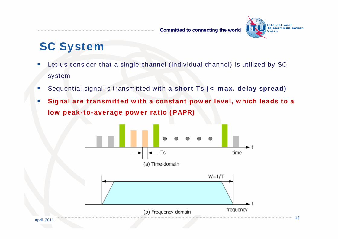
SC System Let us consider that a single channel (individual channel) is utilized by SC Let us consider that a single channel (individual channel) is utilized by SC
system
Sequential signal is transmitted with a short Ts (< max. delay spread)
Signal are transmitted with a constant power level, which leads to a
low peak-to-average power ratio (PAPR)
April, 2011 14

Committed to connecting the world
SC System The standard structure of SC transmissionThe standard structure of SC transmission
Pulse-shaping filter implemented with a square root-raised cosine (SRRC)
filter (Finite impulse response)
It is used to eliminate interference from adjacent channels in the frequency
domain
Whereas, it causes an inter-symbol interference (ISI) by overlapping
subsequent symbols on the same channel
Non-linear amplifier Non linear amplifier
April, 2011 15

Committed to connecting the world
The structure of SC reception
SC SystemThe structure of SC reception
The receiver performs reverse process to the SC transmission
Receive signal suffers from ISI effect due to short Ts
Basically, ISI effect can be mitigated through a channel equalizer
implemented with a linear/non-linear FIR filter
April, 2011 16

Committed to connecting the world
SC System Understanding of channel equalization in terms of frequency-domainUnderstanding of channel equalization in terms of frequency domain
April, 2011 17

Committed to connecting the world
Equalizer properties used for SC system
SC SystemEqualizer properties used for SC system
Time-domain equalizer (TDE) implemented a FIR filter has a high
computational complexity
The total tap-length depends on the maximum delay spread and multipath
power
Efficient implementation could be archived through an adaptive filtering Efficient implementation could be archived through an adaptive filtering
scheme
Adaptive filtering would degrade the equalizer performance over a multipath
fading channel, since the adaptation could not follow the fading degree
The such problems could be resolved by using a frequency-domain equalizer
(FDE) which requires additional receiver signal processing (FDE), which requires additional receiver signal processing.
April, 2011 18
Committed to connecting the world
Summary
Key properties of SC System Summary
SC signal guarantees a low PAPR by controlling the transmit power in linear
region of amplifier
which means it can cover a wide-range service area with a high power emission
and without additional repeater, such as relay
Channel equalization has a high computational complexity and low Channel equalization has a high computational complexity and low
tracking capability to multipath fading channel
SC receiver is robust to frequency and timing offset effects, since it just uses
single carrier
April, 2011 19

Committed to connecting the world
OFDM System OFDM is a subset of FDM in which a single channel utilizes multiple sub-OFDM is a subset of FDM in which a single channel utilizes multiple sub
carriers on adjacent frequencies
In addition, the sub-carriers in an OFDM system are overlapped to maximize
spectral efficiency
Ordinarily, overlapping adjacent channels can interfere with one another.
However, sub-carriers in an OFDM system are precisely orthogonal to one
another
April, 2011 20
Committed to connecting the world
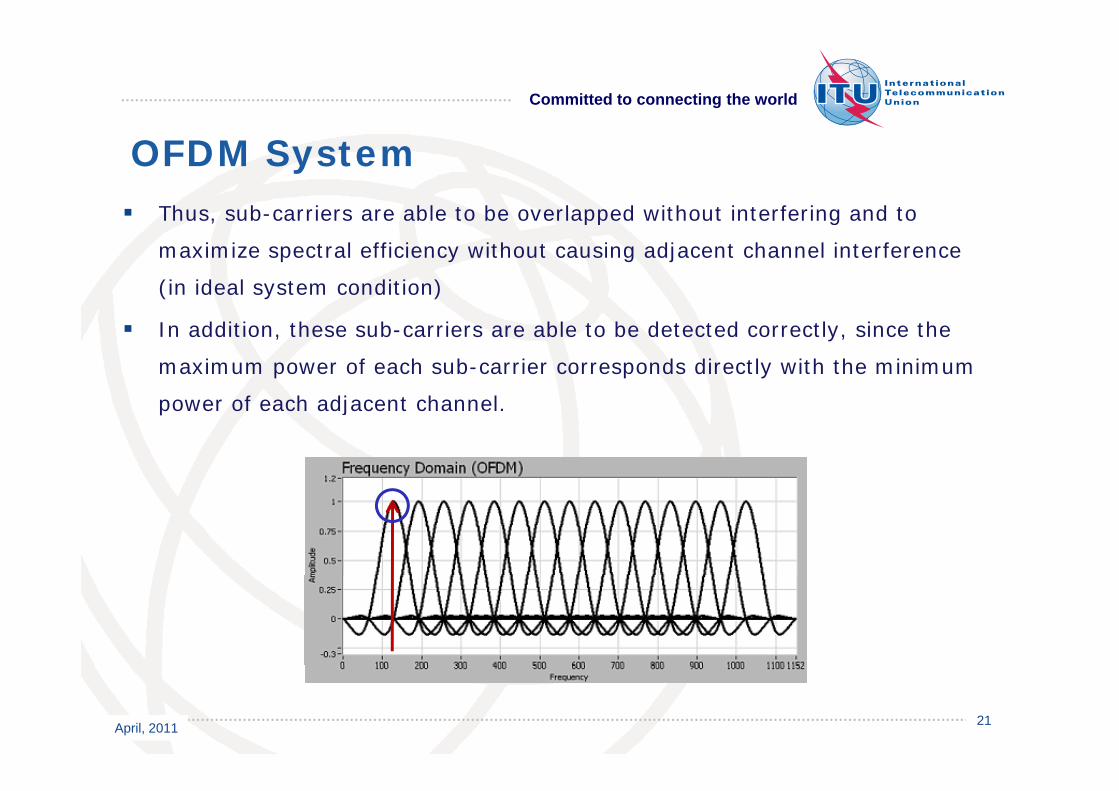
OFDM System Thus sub-carriers are able to be overlapped without interfering and to Thus, sub carriers are able to be overlapped without interfering and to
maximize spectral efficiency without causing adjacent channel interference
(in ideal system condition)
In addition, these sub-carriers are able to be detected correctly, since the
maximum power of each sub-carrier corresponds directly with the minimum
f h dj h lpower of each adjacent channel.
April, 2011 21

Committed to connecting the world
OFDM System Basic concept of OFDM: Rectangle pulse-shaping on the time-domainBasic concept of OFDM: Rectangle pulse shaping on the time domain
(a) DC centered spectrum with equally spaced zeros
(b) Shift spectrum with linear phase on DC pulse: move spectrum to first
spectral zero
April, 2011 22

Committed to connecting the world
OFDM System Basic concept of OFDM: Rectangle pulse-shaping on the time-domainBasic concept of OFDM: Rectangle pulse shaping on the time domain
Real and imaginary parts of complex exponential time series: Integer number
of cycles per interval
April, 2011 23

Committed to connecting the world
OFDM System Basic concept of OFDM: Rectangle pulse-shaping on the time-domainBasic concept of OFDM: Rectangle pulse shaping on the time domain
Spectra of complex exponential time series: Integer number of cycles per
interval
April, 2011 24

Committed to connecting the world
OFDM System Basic concept of OFDM: orthogonal transmissionBasic concept of OFDM: orthogonal transmission
Serial-to-parallel (S/P): once the bit-stream composing of N data symbols has been
divided among the individual sub-carriers, each sub-carrier is modulated as if it was an
individual
April, 2011 25

Committed to connecting the world
OFDM System Basic concept of OFDM: orthogonal receptionBasic concept of OFDM: orthogonal reception
April, 2011 26

Committed to connecting the world
Efficient OFDM transmission using inverse discrete Fourier transform (IDFT)
OFDM System Efficient OFDM transmission using inverse discrete Fourier transform (IDFT)
April, 2011 27

Committed to connecting the world
OFDM System OFDM transceiver structure using inverse fast Fourier transform (IFFT) and OFDM transceiver structure using inverse fast Fourier transform (IFFT) and
FFT at transmitter and receiver, respectively
April, 2011 28

Committed to connecting the world
OFDM System OFDM converts the frequency-selective channel to frequency-flat channel in OFDM converts the frequency selective channel to frequency flat channel in
terms of each frequency-bin.
Which means that OFDM system
has more robust transmission
Property than SC system
in such a channel.
April, 2011 29
Committed to connecting the world
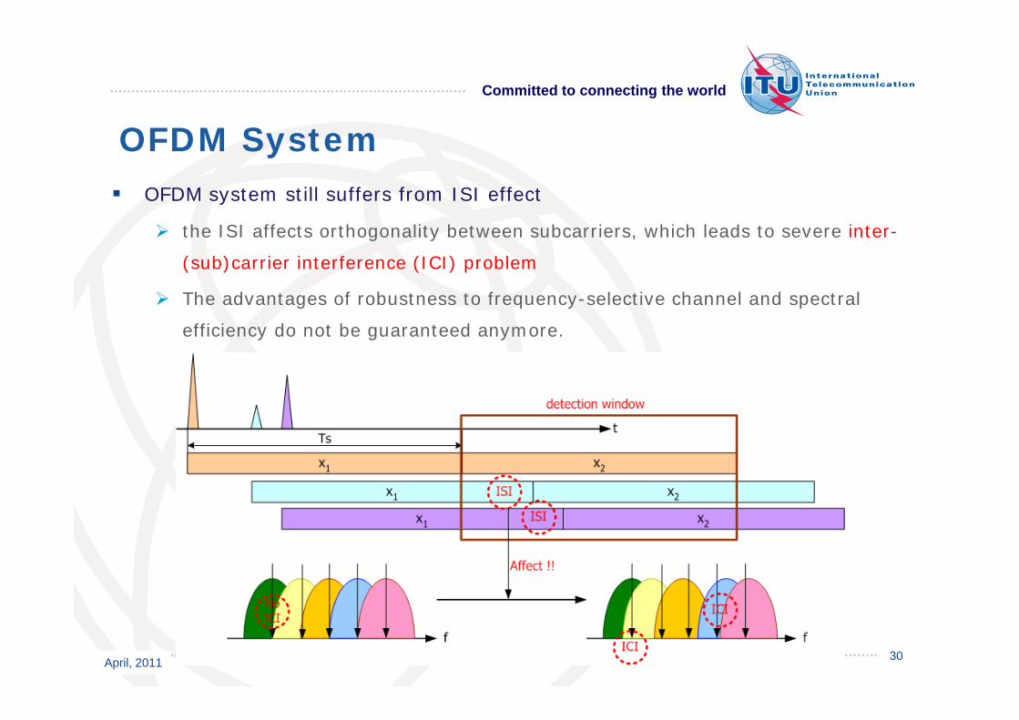
OFDM System OFDM system still suffers from ISI effect OFDM system still suffers from ISI effect
the ISI affects orthogonality between subcarriers, which leads to severe inter-
(sub)carrier interference (ICI) problem
The advantages of robustness to frequency-selective channel and spectral
efficiency do not be guaranteed anymore.
April, 2011 30

Committed to connecting the world
OFDM System Insertion of guard-interval (GI) between OFDM symbols to prevent the ISI Insertion of guard interval (GI) between OFDM symbols to prevent the ISI
effect
The GI length is larger or equal to the maximum delay spread of a channel
GI insertion with zero-padded (ZF) symbol
No ISI, but ZF still affects the orthogonality after FFT operation, since it
broken the continuity of sub-carriers.
April, 2011 31

Committed to connecting the world
OFDM System Insertion of cyclic-prefixed (CP) symbol between OFDM symbols instead of ZP Insertion of cyclic prefixed (CP) symbol between OFDM symbols instead of ZP
symbol
It completely eliminates ISI and ICI.
It maintains subcarrier orthogonality.
April, 2011 32

Committed to connecting the world
OFDM System Key blocks of OFDM TransceiverKey blocks of OFDM Transceiver
Pilot insertion to estimate channel information and the amount of syn. offset
Non-linear amplifier effect to IFFT output
Relation between symbol timing offset and ISI effect
Relation between frequency offset and orthogonality
One-tap channel equalization on the frequency-domain
April, 2011 33

Committed to connecting the world
OFDM System Pilot insertionPilot insertion
Channel information estimation on the time-/-frequency domain
Compensates symbol timing and frequency offsets
Representative pilot patterns
Block-type pilot pattern arrangement
Comb-type pilot pattern arrangement
Scattered-pilot pattern arrangement
Cf) Known-symbol insertion
Known-symbol is sometimes appended in the front of frame block composing Known symbol is sometimes appended in the front of frame block composing
of several OFDM symbols
Known-symbol can be used instead of CP symbol to improve synchronization
April, 2011 34
and channel estimation

Committed to connecting the world
OFDM System Block-type pilot pattern arrangement Block type pilot pattern arrangement
The channel estimation can be performed by either periodically inserting pilot
tones into all sub-carriers (frequency axis)
It is usually used in a severe frequency-selective channel
Channel varies slowly enough so that the channel estimation will have a good
accuracy
April, 2011 35

Committed to connecting the world
OFDM System Comb-type pilot pattern arrangement Comb type pilot pattern arrangement
The number of pilots used for channel estimation is usually much smaller than
the number of sub-carriers
This method is usually used in systems having significant channel variation
over a short period of time
April, 2011 36

Committed to connecting the world
OFDM System Scattered-pilot pattern arrangement Scattered pilot pattern arrangement
Block-type pilot pattern + comb-type pilot pattern
This method is commonly be used in systems having significant doubly
selective channels
April, 2011 37

Committed to connecting the world
OFDM System High PAPR problemHigh PAPR problem
IFFT output shows Gaussian distribution, approximately.
High-peak random signals (a high PAPR problem) are often observed, which
are distorted on the non-linear region of amplifier.
April, 2011 38

Committed to connecting the world
OFDM System OFDM Input and output of non-linear amplifierOFDM Input and output of non linear amplifier
April, 2011 39

Committed to connecting the world
OFDM System ISI effect according to symbol timing offset ISI effect according to symbol timing offset
Symbol timing offset corresponds to the starting position of FFT window.
Cases of timing offset within CP symbol
April, 2011 40

Committed to connecting the world
OFDM System
April, 2011 41

Committed to connecting the world
OFDM System ICI effect according to frequency offset ICI effect according to frequency offset
Due to oscillator mismatch or Doppler Shift
Breaking orthogonality
-> ICI problem
-> performance degradation
April, 2011 42

Committed to connecting the world
OFDM System Efficient receiver processing according to the use of CP symbolEfficient receiver processing according to the use of CP symbol
Convert linear channel matrix to circular matrix after removing CP
symbol
April, 2011 43

Committed to connecting the world
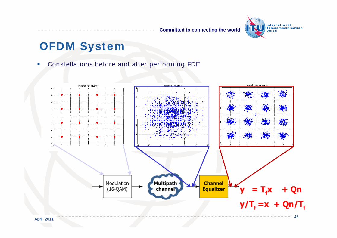
OFDM System Simple one-tap frequency-domain equalization (FDE) realizationSimple one tap frequency domain equalization (FDE) realization
Each subcarrier can be processed independently, which means that only one-
tap multiplier is sufficient in term of implementation.
Consequently, it is obvious that the FDE used for OFDM system has lower
computational complexity than TED for SC system
April, 2011 44

Committed to connecting the world
OFDM System An estimation of channel frequency response (CFR) using comb-type pilot An estimation of channel frequency response (CFR) using comb type pilot
arrangement
Calculate the channel estimates at the pilot subcarriers
Interpolate the estimates for the other subcarriers
1
Channel, Bandwidth, and Samples
-1 -0.8 -0.6 -0.4 -0.2 0 0.2 0.4 0.6 0.8 10
0.5
1 Zero PackedSpectral Samples
-1 -0.8 -0.6 -0.4 -0.2 0 0.2 0.4 0.6 0.8 10
0.5Spectral Samples
andExtended Reflection
1 InterpolatedSpectral Points
-1 -0.8 -0.6 -0.4 -0.2 0 0.2 0.4 0.6 0.8 10
0.5Spectral Points
0.01Magnitude of Interpolation Error For In-Band Frequencies
April, 2011 45-1 -0.8 -0.6 -0.4 -0.2 0 0.2 0.4 0.6 0.8 10
0.005
Normalized Frequency
Committed to connecting the world
OFDM System Constellations before and after performing FDE Constellations before and after performing FDE
April, 2011 46

Committed to connecting the world
Robustness to frequency selectivity one-tap equalizer
Key properties of OFDM System Robustness to frequency selectivity, one tap equalizer
Bandwidth efficiency due to the overlapping orthogonal subcarriers
Simultaneous elimination of ISI and ICI (inter carrier interference) by CP ( ) y
symbol
High peak-to-average power ratio (PAPR)
Sensitivity to Doppler: Channel variation within one OFDM symbol duration
incurs inter-carrier interference (ICI)
Applications:
ADSL, Digital Video Broadcast (DVB), Digital Audio Broadcast (DAB), Digital
terrestrial multimedia broadcasting (DTMB) Wireless LAN (IEEE 802 11a) terrestrial multimedia broadcasting (DTMB), Wireless LAN (IEEE 802.11a),
Wireless MAN (WiMax IEEE 802.16), Down-Link [base station to mobile] 3GPP
LTE, etc
April, 2011 47

Committed to connecting the world
Application of OFDM system Orthogonal Frequency-Division Multiple Access (OFDMA)Orthogonal Frequency Division Multiple Access (OFDMA)
A multi-user version of the popular OFDM modulation scheme. Multiple access
is achieved in OFDMA by assigning subsets of subcarriers to individual
This allows simultaneous low data rate transmission from several users.
April, 2011 48

Committed to connecting the world
CP-SC System Cyclic-prefixed SC systemCyclic prefixed SC system
It preserves the advantages of SC system, i.e., low PAPR, wide-range service
coverage
This allows efficient receiver processing,
especially the application of FDE,
h h d b h f C b lwhich is caused by the use of CP symbol
Convert linear channel
matrix to circular matrix
after removing CP symbol
April, 2011

Committed to connecting the world
Application of CP-SC system Single-carrier FDMA (SC-FDMA)Single carrier FDMA (SC FDMA)
Like other multiple access schemes (TDMA, FDMA, CDMA, OFDMA), it deals
with the assignment of multiple users to a shared communication resource
It has an additional FFT/IFFT processing preceding the conventional OFDMA
processing
M lti l i d ibl b i i diff t Multiple access among users is made possible by assigning different users,
different sets of non-overlapping Fourier-coefficients
The distinguishing feature of SC-FDMA is that it leads to a single-carrier g g g
transmit signal, in contrast to OFDMA which is a multi-carrier transmission
scheme.
Owing to its inherent single carrier structure, a prominent advantage of SC-
FDMA over OFDM and OFDMA is that its transmit signal has a lower PAPR.
April, 2011 50

Committed to connecting the world
Application of CP-SC system Single-carrier FDMA (SC-FDMA)Single carrier FDMA (SC FDMA)
April, 2011 51

Committed to connecting the world
Some of the key technologies used in 4G communication systems i e
Key Transmission technologies of 4GSome of the key technologies used in 4G communication systems, i.e.,
WiMAX and LTE, include OFDM, frequency reuse, adaptive modulation,
multi-input multi-output (MIMO), and so on.
The use of OFDM reduces the effects of multipath and delay spread, which is
especially important for lower frequencies and near line of sight (NLOS)
i itransmission
The use of OFDM enables high data bandwidths to be transmitted efficiently
The use of OFDM allows efficient access schemes for the uplink and downlink The use of OFDM allows efficient access schemes for the uplink and downlink
WiMAX : Orthogonal Frequency Division Multiple Access (OFDMA) is used in
both the downlink and uplink
LTE: OFDMA is used for the down link, while Single Carrier-Frequency Division
Multiple Access (SC-FDMA) is used in the uplink.
April, 2011 52

Committed to connecting the world
LTE: SC-FDMA is used in view of the fact that its peak to average power ratio
Key Transmission technologies of 4G LTE: SC FDMA is used in view of the fact that its peak to average power ratio
is small and the more constant power enables high RF power amplifier
efficiency in the mobile handsets - an important factor for battery power
equipment.
April, 2011 53

Committed to connecting the world
Thank you !!
April, 2011 54