of the residual stresses in low pressure … assessment of the residual stresses in low pressure...
TRANSCRIPT

Surface Engineering in Materials Science - 11 S. Seal, and al. TMS (The Minerals, Metals & Materials Society), 2003
AN ASSESSMENT OF THE RESIDUAL STRESSES IN LOW PRESSURE PLASMA SPRAYED COATINGS ON AN ADVANCED COPPER ALLOY
S.V. Raj’, L.J. Ghosn2, A. Agarwa13, T.P. Lachtrupp4
‘N-4S.4 G!enn Research Center; MS 24- I , 21000 Brookpark Rd.; Cleveland, OH, 44135, USA
20hio Aerospace Institute; NASA Gle.nn Research Center, h4S 49-7; Cleveland, OH, 44135, USA
3Plasma Processes, Inc.; Huntsville, AL, 3581 1, USA 4Lambda Research; Cincinnati, OH, 45227-340 1, USA
Abstract
Modeling studies were conducted on low pressure plasma sprayed (LPPS) NiAl top coat applied to an advanced Cu-8(at.%)Cr-4%Nb alloy (GRCop-84) substrate using Ni as a bond coat. A thermal analysis suggested that the NiAl and Ni top and bond coats, respectively, would provide adequate thermal protection to the GRCop-84 substrate in a rocket engine operating under high heat flux conditions. Residual stress measurements were conducted at different depths from the free surface on coated and uncoated GRCop-84 specimens by x-ray diffraction. These data are compared with theoretically estimated values assessed by a finite element analysis simulating the development of these stresses as the coated substrate cools down from the plasma spraying temperature to room temperature.
Introduction
The National Aeronautics and Space Administration (NASA) is currently developing new technologies for use in the next generation of reusable launch vehicles (RLVs). Advanced copper alloys, such as the Cu-8(at.%)Cr-4%Nb (GRCop-84) [l], are being considered for use as liner materials in the combustion chambers and nozzle ramps of these new engines [2,3,4,5]. However, previous experience has shown that copper alloys are subject to a process called “blanching” in rocket engines using liquid hydrogen and liquid oxygen [6]. Furthermore, copper alloy liners undergo thermo-mechanical fatigue, which often results in an initially square cooling channel deforming into dog-house shape. Clearly, there is an urgent need to develop new coatings technology to protect the copper liners from environmental attack inside a rocket chamber and lower its temperature to reduce the probability of deformation and failure by thermo-mechanical fatigue.
NASA’s Glenn Research Center (GRC) is actively developing and characterizing several advanced protective coatings for applying on GRCop-84 liners and nozzle ramps. Nickel alu was chosen as the top coat in this study because of its relatively low density (5900 thermal conductivity (80 W/m/K) and excellent oxidation properties [7]. T characteristics make it a potential candidate for further evaluation as a protective top coat for advanced copper alloys. Additionally, thermal modeling studies suggest that NiAl is likely to be an effective top coat for a GRCop-84 substrate under the high heat flux conditions characteristic of a rocket engine combustion chamber [8]. Figure 1 shows the variation of the absolute temperature, T, at different points across the coating-substrate cross-section as a function of the NiAl coating thickness, t, for a constant Ni bond coat thickness of 0.05 mm deposited on a 1.0 mm thick GRCop- 84 substrate. The temperatures are calculated assuming a 900 s exposure to a hot gas temperature of 3550 K with about 12,365 and 58,285 W m-2 K-’ convective heat transfers on the coated hot and cooled’ sides, respectively, with the cooling fluid maintained at 97 K. These calculations indicate
This is a preprint or reprint of a paper intended for presentation at a conference. Because changes may be made before formal publication, this is made available with the understanding that it will not be cited or reproduced without the Dermission of the author.
https://ntrs.nasa.gov/search.jsp?R=20030025290 2018-06-23T11:05:35+00:00Z

that the NiAl coating thickness should exceed 0.1 mm to ensure that the substrate is maintained below 788 K for these high heat flux conditions.
6 0 0 t ' " " " ' " " ' " ' ' " ' " ' " 0.00 0.05 0.10 0.15 0.20 0.25
Top Coating Thickness t, (mm)
Figure 1: Temperature profile across the NiAUNi/GRCop-84 interfaces as a function of the top coating thickness.
In order to use NiAl effectively as a top coat for GRCop-84, i t is essential that the processing parameters be optimized and the durability of the coating for the expected mission life be demonstrated. It is expected that the low pressure plasma spraying (LPPS) technique is the most cost effective way of applying the bond and top coats onto a GRCop-84 substrate. However, residual stresses develop during LPPS as well as during post-spraying cool down, which are likely to influence coating life and spalling characteristics. The cool down stresses develop due to a mismatch in the thermal expansion and mechanical properties of coatings and substrate. The presence of these residual stresses influences coating spallation, thermal cycling life and fatigue properties of the coated substrate [9]. This paper presents preliminary experimental results on the nature and magnitudes of the residual stresses developed in the NiAl top and Ni bond coats as well as in the GRCop-84 substrates during LPPS. The experimental data are compared with those predicted by finite element analysis (FEA) assuming that the residual stresses develop primarily as the coating-substrate cools from the two plasma spraying temperatures to room temperature.
Experimental Procedures
GRCop-84 disks, 12.7 nun in diameter and either 2 or 3 mm thick, were electro-discharge machined (EDM) from a powder-extruded rod, where the axes of the disks were parallel to the extruded direction. In order to assess the effect of surface finish on the residual stresses, three 2 mm thick specimens were prepared to different levels of surface roughness by a combination of polishing and grit blasting. Two specimens were polished on both sides with emery paper to a final finish on a No. 1000 grit paper. One of these specimens was designated as NASA-1. The other polished specimen, designated as NASA-2, was grit blasted with 60 grit alumina particles at a pressure of about 70 Pa for about 2 s per face at a stand-off distance of about 25 mm. A third specimen, designated as PPI-2, was ground on both sides to a No. 600 grit finish on emery paper. Each face of this specimen was then grit blasted with 120 grit alumina particles at a pressure of about 620 Pa for about 3 s per face using a stand-off distance of about 150 mm. X-ray diffraction residual stress measurements were

made on these three specimens at the free surface and at nominal depths up to about 180 l m in increments of 5 pm using Mn & x-ray radiation, where the material was removed from the specimens by electropolishing to minimize the effects of material removal on the measured values of the residual stress. These measurements were performed employing the two-angle sin’ Y technique. The diffraction lines from the (31 1) planes of the Cu matrix in the GRCop-84 substrate were analyzed in accordance with the SAE J784a standards. The bulk values of the Young’s modulus, E, and Poisson’s ratio,v, were used for converting the measured strains to the macroscopic residual stresses. These data were appropriately corrected for the effects of the penetration of the x- ray radiation into the substrate and for the relaxation of the stresses during e!ec~opo!ishing di;e to material removal.
The Ni bond and the NiAl top coats were deposited on the 3 mm thick specimens by LPPS. The specimens were grit blasted prior to spraying to remove surface oxides. The nominal thicknesses of the top and bond coats were 75-100 and 50 pm, respectively. Residual stress measurements were made at different points across the NiAl/Ni/GRCop-84 cross-section of a specimen with a 75 pm thick top coat using the six-angle sin2 ‘P technique. Diffraction lines were analyzed using Cr K, radiation from the (21 1) planes of the NiAl top coat, Cu & radiation from the (420) planes of the Ni bond coat and Mn & radiation from the (3 11) planes of the Cu matrix in the substrate. The residual stresses were measured at different depths: (a) at the free surface and at a nominal depth of about 30 pm in the NiAl top coat; (b) at the NiAl/Ni interface lying approximately 40 pm from the free surface; and (c) at the Ni/GRCop-84 interface and within the substrate corresponding to approximate depths of 100, 130 and 165 pm, respectively, from the free surface.
,Cooled w m I
Top Coat :oat I
Figure 2: Finite element mesh lying across the r-z plane of the coated disk.
Modeling Procedures
The accumulated residual stresses developed during cool down after LPPS were calculated by FEA using published thermophysical and temperature dependent mechanical properties data for Ni AI, Ni and GRCop-84. Other stresses, such as quenching stresses when the molten droplets splat cool after hitting the substrate, are ignored. Finite element meshes of the various layers were constructed with 2-D axisymmetric eight node elements. The interfaces were assumed to be flat and the edge effects are ignored. A typical finite element mesh is shown in Fig. 2 for a substrate thickness of 1 mm. The

stresses and strains within each layer were determined using elastic-plastic and power law creep analyses. Since the actual temperature-time profile was not measured in this study, the temperatures through the top and bond coats and the substrate were calculated assuming that all the layers were at two maximum temperatures of either 523 or 923 K for 200 s during LPPS. The subsequent cool down from these uniform temperatures to room temperature was assumed to occur by natural convection.
Results and Discussion
Figure 3 shows the as-polished cross-section of the LPPS coated substrate, where the top and bond coats were about 100 and 50 pm, respectively. The characteristic layered microstructure typical of the as-sprayed coating is visible in the NiAl top coat. The Ni bond coat was essentially void free but some small cavities were observed in the NiAl top coat although their volume fraction was not quantitatively determined. The top and bond coats were generally defect-free along their lengths except in some isolated instances, where an occasional void was observed.
Figure 3: Micrograph of the cross-section of an as-sprayed GRCop-84 substrate showing the microstructures of the NiAl top and the Ni bond coats, respectively.
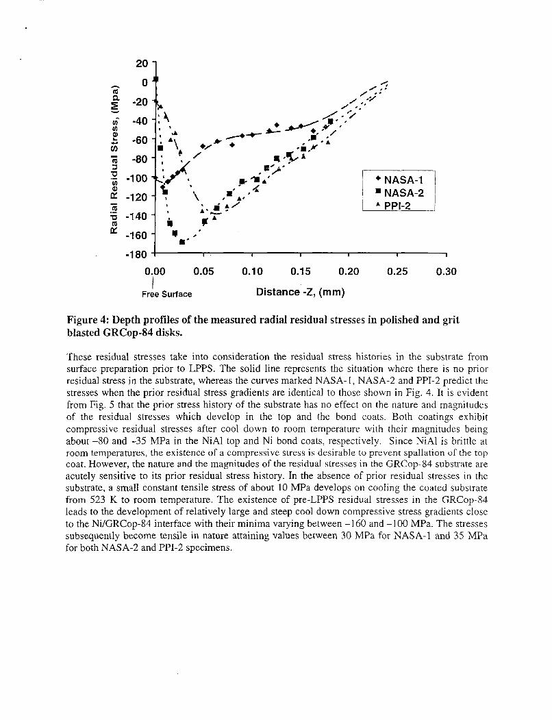
Figure 4 shows the variation of the residual stresses with depth from the free surface for NASA-1, NASA-2 and PPI-2. The curves represent an eight order polynomial regression fit to the experimental data. A close examination of the data reveals certain common trends as well as clear distinctions in the experimental data for these specimens. For example, the residual stresses in all three specimens are compressive in nature below the free surface to depths of 0.18 mm. Extensions of the polynomial curves suggest that the residual stresses are likely to become tensile in nature slightly beyond 0.25 mm for all three specimens. Likewise, the regressed curves exhibit points of minimum stress located some distance from the free surface. These minima occur at 7.5, 30 and 60 pm for NASA-1, NASA-2 and PPI-2, respectively, with the corresponding residual stresses being -1 10, -170 and -145 m a . At the free surface, both the grit-blasted specimens, NASA-2 and PPI-2, exhibit low or no measurable stresses unlike the as-polished specimen, NASA-1, which has a compressive stress of about -100 m a . Although the initial stress gradients are somewhat different prior to the minima for the grit-blasted specimens with NASA-2 exhibiting a steeper gradient, the magnitudes and shapes of the curves are almost identical for these two specimens beyond the minima. In contrast, the stresses are less compressive in NASA-1 beyond a depth of 23 pm with the stress depth profile showing a near plateau between 50 and 150 pm.
2o 1 h 0 m
-20 Y
ui -40 v) E -60 in ii -80 3
2 v) -100
2 -120 - m m 5 -140
-160
a "p'
L -.' \ *NASA-1 I 1 =NASA-2 I j A PPI-2
-180 I I I I I I
0.00 0.05 0.1 0 0.1 5 0.20 0.25 0.30
Distance -Z, (mm) Free Surface I
Figure 4: Depth profiles of the measured radial residual stresses in polished and grit blasted GRCop-84 disks.
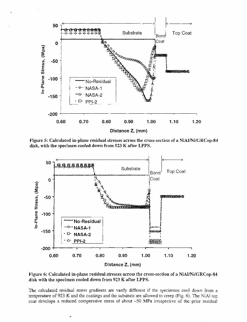
These residual stresses take into consideration the residual stress histories in the substrate from surface preparation prior to LPPS. The solid line represents the situation where there is no prior residual stress in the substrate, whereas the curves marked NASA-1, NASA-2 and PPI-2 predict the stresses when the prior residual stress gradients are identical to those shown in Fig. 4. It is evident from Fig. 5 that the prior stress history of the substrate has no effect on the nature and magnitudes of the residual stresses which develop in the top and the bond coats. Both coatings exhibit compressive residual stresses after cool down to room temperature with their magnitudes being about -80 and -35 MPa in the NiAl top and Ni bond coats, respectively. Since NiAl is brittle at room temperatures, the existence of a compressive stress is desirable to prevent spallation of the top coat. However, the nature and the magnitudes of the residual stresses in the GRCop-84 substrate are acutely sensitive to its prior residual stress history. In the absence of prior residual stresses in the substrate, a small constant tensile stress of about 10 MPa develops on cooling the coated substrate from 523 K to room temperature. The existence of pre-LPPS residual stresses in the GRCop-84 leads to the development of relatively large and steep cool down compressive stress gradients close to the Ni/GRCop-84 interface with their minima varying between -160 and -100 MPa. The stresses subsequently become tensile in nature attaining values between 30 MPa for NASA-1 and 35 MPa for both NASA-2 and PPI-2 specimens.
-200 -I I 1 I I I I
0.60 0.70 0.80 0.90 1 .oo 1.10 1.20
Distance Z, (mm)
Figure 5: Calculated in-plane residual stresses across the cross-section of a NiAVNi/GRCop-84 disk, with the specimen cooled down from 523 K after LPPS.
50 < -
-50 Y, e zi g -100
4 m - f: -
-1 50
-200
No-Residual - -O- NASA-1 -EI- NASA-2 - A- PPI-2
I I I I
0.60 0.70 0.80 0.90 1 .oo 1.10 1.20
Distance Z, (mm)
Figure 6: Calculated in-plane residual stresses across the cross-section of a NiAVNi/GRCop-84 disk with the specimen cooled down from 923 K after LPPS.
The calculated residual stress gradients are vastly different if the specimens cool down from a temperature of 923 K and the coatings and the substrate are allowed to creep (Fig. 6). The NiAl top coat develops a reduced compressive stress of about -50 MPa irrespective of the prior residual
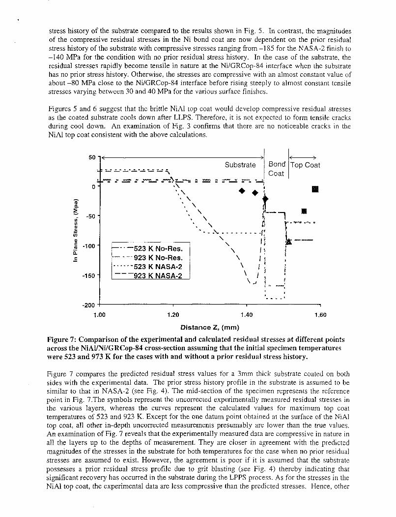
stress history of the substrate compared to the results shown in Fig. 5 . In contrast, the magnitudes of the compressive residual stresses in the Ni bond coat are now dependent on the prior residual stress history of the substrate with compressive stresses ranging from -1 85 for the NASA-2 finish to -140 MPa for the condition with no prior residual stress history. In the case of the substrate, the residual stresses rapidly become tensile in nature at the Ni/GRCop-84 interface when the substrate has no prior stress history. Otherwise, the stresses are compressive with an almost constant value of about -80 MPa close to the Ni/GRCop-84 interface before rising steeply to almost constant tensile stresses varying between 30 and 40 MPa for the various surface finishes.
Figures 5 and 6 suggest that the brittle NiAl top coat would develop compressive residual stresses as the coated substrate cools down after LLPS. Therefore, it is not expected to form tensile cracks during cool down. An examination of Fig. 3 confirms that there are NiAl top coat consistent with the above calculations.
50 i< >I
0
A m 0.
E - -50
E 5
u) u)
0) : -100 - a C -
-1 50
no noticeable cracks in the
- Bond Topcoat Coat
- - -523 K No-Res. 923 K No-Res.
- . - - - - 5 2 3 K NASA-2
-200 I I I 1
1 .oo 1.20 1.40 1.60
Distance Z , (mm)
Figure 7: Comparison of the experimental and calculated residual stresses at different points across the NiAl/Ni/GRCop-S4 cross-section assuming that the initial specimen temperatures were 523 and 973 K for the cases with and without a prior residual stress history.
Figure 7 compares the predicted residual stress values for a 3mm thick substrate coated on both sides with the experimental data. The prior stress history profile in the substrate is assumed to be similar to that in NASA-2 (see Fig. 4). The mid-section of the specimen represents the reference point in Fig. 7.The symbols represent the uncorrected experimentally measured residual stresses in the various layers, whereas the curves represent the calculated values for maximum top coat temperatures of 523 and 923 K. Except for the one datum point obtained at the surface of the NiAl top coat, all other in-depth uncorrected measurements presumably are lower than the true values. An examination of Fig. 7 reveals that the experimentally measured data are compressive in nature in all the layers up to the depths of measurement. They are closer in agreement with the predicted magnitudes of the stresses in the substrate for both temperatures for the case when no prior residual stresses are assumed to exist. However, the agreement is poor if i t is assumed that the substrate possesses a prior residual stress profile due to grit blasting (see Fig. 4) thereby indicating that significant recovery has occurred in the substrate during the LPPS process. As for the stresses in the NiAl top coat, the experimental data are less compressive than the predicted stresses. Hence, other

contributions presumably due to splat cooling of the droplets and “peening” effects as each new coating layer is deposited on top of a previous one must also be considered [lo].
Summary
The residual stresses developed in a NiAl/Ni/GRCop-84 composite as it cools after low pressure plasma spraying has been modeled. The predicted stresses are compared with those measured experimentally by x-ray diffraction. These stresses were observed to be in compressive in nature. It is demonstrated that the calculated and the experimental results are i n reasonable agre.emen1 in the substrate but not in the NiAl top coat.
References
1. D. L. Ellis and G.M. Michal, “Mechanical and Thermal Properties of Two Cu-Cr-Nb Alloys and NARloy-Z, ” NASA CR-198529, NASA Lewis Research Center, Cleveland, OH (1996).
2. R. Holmes, D. Ellis and T. McKechnie, “Robust Low Cost Aerospike/RLV Combustion Chamber by Advanced Plasma Process,” Space Congress Proceedings 36* Space ConEress: Countdown to the Millennium Proceedings, April 27-30, 1999, Canaveral Council of Technical Societies, Cape Canaveral, FL (1999).
3. D. Ellis and D. Keller, “Thermophysical Properties of GRCop-84, ” NASA CR 2000-210055, NASA Glenn Research Center, Cleveland, OH (2000).
4. R. Hickman, T. McKechnie and R. Holmes, “Material Properties of Vacuum Plasma Sprayed Cu-8Cr-4Nb for Liquid Rocket Engines”, 37’ AIAA/ASME/ASEE Joint Propulsion Conference-8- 11, July. 2001, Salt Lake City, UT, Paper No. AIAA 2001-3693, AIAA, Reston, VA (2001).
5 . S. Elam, J. Lee, R. Holmes and F. Zimmerman, “Lightweight Chambers for Thrust Assemblies”, 52nd Intern. Astronautical Conpress: October 1-5. 2002. Toulouse, France, International Astronautical Federation, Paris, France, pp. 1-1 1 (2001).
6. D.B. Morgan and A.C. Kobayashi, “Main Chamber Combustion and Cooling Technology Study”, NASA CR 184345, NASA Marshall Space Flight Center, Huntsville, AL (1989).
7. C. A. Barrett, “EfSect of 0.1 at-percent Zirconium on the Cyclic Oxidation Resistance of Beta- NiAl,” Oxid. Metals, 30 (1988), 361-390.
8. L. J. Ghosn and S. V. Raj, “Residual Streeses in Thermal Barrier Coatings for a Cu-8Cr-4Nb,” NASA TM 2002-21 1561, NASA Glenn Research Center, Cleveland, OH (2002).
9. Progressively Deposited Coatings: I . Planar Geometry” Thin Solid Film, 36, pp. 23-33 (1997).
Y.C. Tsui and T.W. Clyne, “An Analytical Model for Predicting Residual Sstresses in
10. J. Matejicek and S. Sampath, “Intrinsic Residual Stresses in Single Spluts Produced by Thermal Spray Processes,” Acta Mater., 49, pp. 1993-1999 (2001).