of ctf toward demo development requirements and the role ... · - tritium consumption/tritium...
TRANSCRIPT

On Fusion Nuclear TechnologyDevelopment Requirements and the Role
of CTF toward DEMO
Mohamed Abdou
With input from A. Ying, M. Ulrickson, D. K. Sze, S.Willms, F. Najmabadi, J. Sheffield, M. Sawan, C.Wong, R. Nygren, P. Peterson, S. Sharafat, R.
Buende, N. Morley, L. Waganer, D. Petti, E. Cheng, M.Peng, and L. Cadwallader
Note• Primarily for MFE DEMO (some aspects are relevant to IFE)

Fusion Nuclear Technology (FNT)
FNT Components from the edge of the Plasma to TF Coils (Reactor “Core”)
1. Blanket Components
2. Plasma Interactive and High Heat Flux Components
3. Vacuum Vessel and Shield Components
4. Tritium Processing Systems
5. Instrumentation and Control Systems
6. Remote Maintenance Components
7. Heat Transport and Power Conversion Systems
a. divertor, limiterb. rf antennas, launchers, wave guides, etc.
Other Components affected by the Nuclear Environment

Short Answers to Key Questions
1. Can IFMIF do Blanket / FNT testing? NoNoIFMIF provides data on “radiation damage” effects on basicproperties of structural materials in “specimens”.
Blanket Development is something ELSEELSE
2. What do we need for Blanket/PFC Development?
A – Testing in non-fusion facilities (laboratory experiments plusfission reactors plus accelerator based neutron sources)
Conclusion from previous international studies
“The feasibility, operability, and reliability of blanket/FNT systems“The feasibility, operability, and reliability of blanket/FNT systemscannot be established without testing in fusion facilities.”cannot be established without testing in fusion facilities.”
That we have been asked the past few months
(IFMIF’s role was explained by S. Zinkle. This presentation explains blanket/FNTdevelopment)(No IFMIF report nor any of the material or blanket experts ever said this.)
B – Extensive Testing in Fusion FacilitiesAND
(e.g. FINESSE, ITER Test Blanket Working Group, IEA-VNS):

3. What are the Fusion Testing Requirements forBlankets/FNT?
Short Answers to Key Questions (Cont’d)
Based on extensive technical international studies, many publishedin scholarly journals, the testing requirements are:
Neutron wall load of >1 MW/m2 with prototypical surface heat flux,steady state (or long pulse > 1000 s with plasma duty cycle>80%), surface area for testing >10 m2, testing volume > 5 m3,neutron fluence > 6 MW·y/m2
4. Can the present ITER (FEAT) serve as the fusionfacility for Blanket/FNT Testing? NoNo- ITER (FEAT) parameters do not satisfy FNT testing requirements
Short plasma burn (400 s), long dwell time (1200 s), low wall load(0.55 MW/m2), low neutron fluence (0.1 MW·y/m2)
- ITER short burn/long dwell plasma cycle does not even enabletemperature equilibrium in test modules, a fundamental requirementfor many tests. Fluence is too low.
Short Answers to Key Questions (Cont’d)
5. Is it prudent to impose FNT testing requirements onITER? NoNo
- The optimum approach is two fusion devices: one for plasmaburn; the other for FNT testing. (Conclusion of many studies.)
- Tritium consumption/tritium supply problem, complete redesignis costly, schedule is a problem.
6. What is CTF?• The idea of CTF is to build a small size, low-fusion power DT plasma-
based device in which Fusion Nuclear Technology experiments canbe performed in the relevant fusion environment at the smallestpossible scale and cost.- In MFE: small-size, low fusion power can be obtained in a low-Q plasma device.
- Equivalent in IFE: reduced target yield and smaller chamber radius (W. MeierPresentation).
• This is a faster, much less expensive approach than testing in a large,ignited/high Q plasma device for which tritium consumption, and cost ofoperating to high fluence are very high (unaffordable!, not practical).
7. Is CTF Necessary? Most Definitely, Most Definitely, but this is not thebut this is not theright questionright question. . The right question is:
Will ITER plus CTF as the only DT Fusion Facilitiesbe sufficient to have a successful DEMO?
Short Answers to Key Questions (Cont’d)
Maybe, but we know for sure that, at a minimum, we need:
• extensive developmental programs on ITER, CTF, and non-fusion facilities.
• this work to begin sooner rather than later, before the tritiumsupply window closes, to have any hope that DEMO starts in 35years.
[And remember how many fission test reactors were built.]

Blanket/PFC Concepts,FNT Issues, and Testing
Requirements
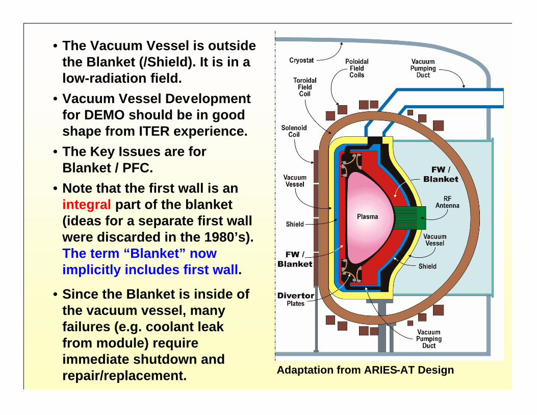
• The Vacuum Vessel is outsidethe Blanket (/Shield). It is in alow-radiation field.
• Vacuum Vessel Developmentfor DEMO should be in goodshape from ITER experience.
• The Key Issues are forBlanket / PFC.
• Note that the first wall is anintegral part of the blanket(ideas for a separate first wallwere discarded in the 1980’s).The term “Blanket” nowimplicitly includes first wall.
• Since the Blanket is inside ofthe vacuum vessel, manyfailures (e.g. coolant leakfrom module) requireimmediate shutdown andrepair/replacement. Adaptation from ARIES-AT Design
Blanket and PFC Serve Fundamental and NecessaryFunctions in a DT Fusion System
• TRITIUM BREEDING at the rate required to satisfy tritium self-sufficiency
• TRITIUM RELEASE and EXTRACTION• Providing for PARTICLE PUMPING (plasma exhaust)• POWER EXTRACTION from plasma particles and radiation
(surface heat loads) and from energy deposition of neutrons andgammas at high temperature for electric power production
• RADIATION PROTECTION
Important Points• All in-vessel components (blankets, divertor, vacuum pumping, plasma heating
antenna/waveguide, etc.) impact ability to achieve tritium self-sufficiency.• High temperature operation is necessary for high thermal efficiency. And for
some concepts, e.g. SB, high temperature is necessary for tritium release andextraction.
• All the above functions must be performed safely and reliably.

Specific Blanket Options (Worldwide)
SiC Insert
SiC/SiC
Ferritic
---
---
Pb-17Li
He
Pb-17Li
Pb-17Li
ARIESStudies
CoatingFerritic/V
Ferritic
Ferritic
---
He
Li
Flibe/Flinabe
He
Li
Flibe(Flinabe)/Be
Li-Ceramic/Be
USAUSAAPEX*Studies
Ferritic
Ferritic
HeH2O & He
Flibe
Li2O(Li2TiO3)/Be
Flibe
JAJADemo
LHD (Univ.)
SiC InsertFerritic
SiC/SiC
SiC/SiC
---
He
---
Pb-17Li & He
He
Pb-17Li
Pb-17Li
Li-Ceramic/Be
Pb-17Li
2nd generationplants
Ferritic+
Ferritic---
He 0.13MPa
He (8 MPa)He (8 MPa)
Pb-17LiLi-Ceramic/Be
EUEUDemo & 1st
generationplants
InsulatorStructurePurgeCoolantBreeder/MultiplierOptions
* APEX considers both bare solid wall and thin (2 cm) plasma-facing liquid on first wall and divertor+ Advanced Ferritic Steels are often proposed for designs using ferritic

A Helium-Cooled Li-Ceramic Breeder Concept is Considered forEU (Similar Concept also in Japan, USA)
Material FunctionsBeryllium (pebble bed) for neutronmultiplicationCeramic breeder(Li4SiO4, Li2TiO3, Li2O, etc.)for tritium breedingHelium purge to remove tritium through the“interconnected porosity” in ceramic breederHigh pressure Helium cooling in structure(advanced ferritic)
Several configurations exist toovercome particular issues

Geometric Configurations and Material Interactions amongbreeder/Be/coolant/structure represent critical feasibility issues
that require testing in the fusion environment
• Configuration (e.g. wall parallel or“head on” breeder/Be arrangements)affects TBR and performance
• Tritium breeding and release
• Thermomechanics interactions of breeder/Be/coolant/structure involvemany feasibility issues (cracking of breeder, formation of gaps leading tobig reduction in interface conductance and excessive temperatures)
- Max. allowable temp.(radiation-induced sintering insolid breeder inhibits tritiumrelease; mass transfer, e.g.LiOT formation)
- Min. allowable Temp. (tritiuminventory, tritium diffusion
- Temp. window (Tmax-Tmin)limits and ke for breederdetermine breeder/structureratio and TBR
Tritium release characteristics are highlytemperature dependent
Osi : Li4SiO4
Mti : Li2TiO3
MZr : Li2ZrO3

ARIES-AT blanket with SiC composite structure and Pb-17Licoolant and tritium breeder
Pb-17Li OperatingTemperature
Inlet: 654 oCOutlet: 1100 oC
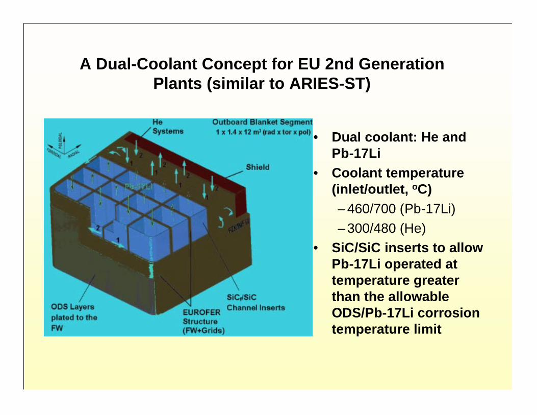
A Dual-Coolant Concept for EU 2nd GenerationPlants (similar to ARIES-ST)
• Dual coolant: He andPb-17Li
• Coolant temperature(inlet/outlet, oC)– 460/700 (Pb-17Li)
– 300/480 (He)• SiC/SiC inserts to allow
Pb-17Li operated attemperature greaterthan the allowableODS/Pb-17Li corrosiontemperature limit

MHD and Insulators are Critical IssuesEngineering Feasibility will be proven only through Integrated Tests
Key issue: disparate thermal expansion coefficient, low tensile strength and poorductility of ceramic coatings compared to pipe wall heated under cyclic operationswill lead to significant cracking of the coating. Once a crack is generated it forms anelectrical circuit for leakage current – leading to critical increase MHD pressuredrop.
MHD is critical issue for liquid-metal-cooled blankets and PFC’sInsulators are required: Ceramic coatings have been proposed
Therefore, rapid self-healing of coating ismandatory. Healing speed will depend on thedetails of crack generation rate and size –currently unknown and unpredictable.
Meaningful testing of the performance of thisthin insulating layer can only be performed in amulti-effect environment with: (1) hightemperature and strong temperature gradients(volumetric nuclear heating), (2) electric andmagnetic fields, (3) stress and stress gradients,(4) prototypic material and chemical systems andgeometry, and (5) radiation effects.
Insulating layer
Leakagecurrent
CrackLeakage of Electric currents in 2D channelwith cracked insulator coating
Conducting wall

PFC Development• Highest heat flux component in
a fusion device (10-20 MW/m2)
• Closely coupled to plasmaperformance
• Cyclic Power excursions (ELMs& Disruptions) erosion lifetime
• Limited materials choices (W,Mo, Ta, Nb?, C?, Liquids: Li, Ga,Sn)
• High neutron fluence
• Tritium retention (C)
• Joining, fabrication, and coolantcompatibility issues
ITER-FEAT DivertorCassette
Note: PFC, Blanket, rf antennas, and other in-vessel components in reactor“core” must be compatible and they collectively play a major role in key FNTissues, e.g. Tritium Self-Sufficiency.

Role of Liquid Walls in Blanket and PFC Development
• Liquid Walls are being pursued in the US for manypotential benefits (removal of high surface heatflux, increased potential for disruption survivability,reduced thermal stresses in structural materials,possible improvements in plasma confinementand stability, etc.)
• The focus of the on-going R&D Program inlaboratory experiments and plasma devices is ona thin liquid wall (~2 cm) on the plasma-facing sideof the first wall and divertor
• No major changes in Fusion Nuclear TechnologyDevelopment Pathways are necessary for thinliquid walls. If thin liquid walls prove feasible (e.g.from NSTX liquid surface module), they can beeasily incorporated into CTF (and also, hopefully,into ITER at later stages) and DEMO

Summary of Critical R&D Issues for Fusion Nuclear Technology
• D-T fuel cycle tritium self-sufficiency2. Tritium inventory and recovery in the solid/liquid breeders under
actual operating conditions
3. Thermomechanical loadings and response of blanket and PFCcomponents under normal and off-normal operation
4. Materials compatibility5. Identification and characterization of failure modes, effects, and
rates in blankets and PFC’s
6. Effect of imperfections in electric (MHD) insulators in liquid metalcooled blanket and PFC under thermal/mechanical/electrical/nuclearloading
7. Tritium permeation and inventory in blanket and PFC
8. Radiation Shielding: accuracy of prediction and quantification ofradiation protection requirements
9. Lifetime of blanket, PFC, and other FNT components
10. Remote maintenance with acceptable machine shutdown time.
FNT Testing Requirements

Key Fusion Environmental Conditions for Testing FusionNuclear Components
Neutrons (fluence, spectrum, spatial and temporal gradient)- Radiation Effects
(at relevant temperatures, stresses, loading conditions)- Bulk Heating- Tritium Production- ActivationHeat Sources (magnitude, gradient)- Bulk (from neutrons)- SurfaceParticle Flux (energy and density)Magnetic Field- Steady Field- Time-Varying FieldMechanical Forces- Normal- Off-NormalThermal/Chemical/Mechanical/Electrical/Magnetic InteractionsSynergistic Effects- Combined environmental loading conditions
- Interactions among physical elements of components

Neutron Effects(1)
Bulk
Nuclear Heating(2)
Non-
Nuclear(3)
Thermal/ Mechanical/ Chemical/ Electrical(4)
Integrated Synergistic
Non-Neutron Test Stands
no no partial partial no
Fission Reactor
partial partial no no no
Accelerator-Based Neutron Source
partial no no no no
(1) radiation damage, tritium and helium production, transmutations(2) nuclear heating in a significant volume(3) magnetic field, surface heat flux, particle flux, mechanical forces(4) thermal-mechanical-chemical-electrical interactions (normal and off normal)* From Fusion Technology, Vol. 29, pp 1-57, January 1996
Table XV*: Capabilities of Non-Fusion Facilities for Simulation of KeyConditions for Fusion Nuclear Component Experiments

FNT Development for DEMO:
Need for FNT Testing in Fusion Facilities
Conclusions of International Experts:
--Non-fusion facilities cannot fully resolve any critical issuefor blankets or PFC’s
--There are critical issues for which no significant informationcan be obtained from testing in non-fusion facilities (Anexample is identification and characterization of failuremodes, effects and rates)
--The Feasibility of Blanket/PFC Concepts can NOT beestablished prior to testing in fusion facilities
Note: Non-fusion facilities can and should be used to narrow material and design conceptoptions and to reduce the costs and risks of the more costly and complex tests in thefusion environment. Extensive R&D programs on non-fusion facilities should start now.

A fusion test facility allows SIMULTANEOUS testing of integrated (synergistic)effects, multiple effects, and single effects
Testing in a Fusion Facility is the fastest approach to Blanket and FusionDevelopment to Demo
- Allows understanding through single and multiple effects tests under same conditions- Provides “direct” answer for synergistic effects
Specimen
Capsule test Submodule Test Module
9 cm
2.5 cm
50 cm
10.8 cm10
0 cm
* Figures are not to scale. Note Dimensions

• Initial exploration ofperformance in a fusionenvironment
• Calibrate non-fusion tests
• Effects of rapid changes inproperties in early life
• Initial check of codes and data
• Develop experimentaltechniques and testinstrumentation
• Narrow material combinationand design concepts
• 10-20 test campaigns, each is 1-2 weeks
• Tests for basic functions andphenomena (tritium release / recovery,etc.), interactions of materials,configurations
• Verify performance beyond beginningof life and until changes in propertiesbecome small (changes are substantialup to ~ 1-2 MW · y/m
2)
• Data on initial failure modes andeffects
• Establish engineering feasibility ofblankets (satisfy basic functions &performance, 10 to 20% of lifetime)
• Select 2 or 3 concepts for furtherdevelopment
• Identify failure modes and effects
• Iterative design / test / fail / analyze /improve programs aimed atimproving reliability and safety
• Failure rate data: Develop a database sufficient to predict mean-time-between-failure with sufficientconfidence
• Obtain data to predict mean-time-to-replace (MTTR) for both plannedoutage and random failure
• Develop a data base to predictoverall availability of FNTcomponents in DEMO
Size of TestArticle
RequiredFluence(MW-y/m2)
Stage:
Stages of FNT Testing in Fusion Facilities
Sub-Modules
~ 0.3
I
Fusion“Break-in”
II III
Design Concept& Performance
Verification
Component EngineeringDevelopment &
Reliability Growth
1 - 3 > 4 - 6
ModulesModules/ Sectors
DEMO

- These requirements have been extensively studied over the past 20 years, and they have been agreed to internationally(FINESSE, ITER Blanket Testing Working Group, IEA-VNS, etc.)
- Many Journal Papers have been published (>35)- Below is the Table from the IEA-VNS Study Paper (Fusion Technology, Vol. 29, Jan 96)
1 to 2
Steady Stateb
1 to 2
0.31 to 34 to 6c
>6
>10>5
>4
Neutron wall loada (MW/m2)
Plasma mode of operationMinimum COT (periods with 100% availability) (weeks)
Neutron fluence at test module (MW·y/m2)
Stage I: initial fusion break-in Stage II: concept performance verification (engineering feasibility) Stage IIIc: component engineering development and reliability growth
Total neutron fluence for test device (MW·y/m2)
Total test area (m2)Total test volume (m3)
Magnetic field strength (T)
ValueParameter
FNT Requirements for Major Parameters for Testing in Fusion Facilities with Emphasis onTesting Needs to Construct DEMO Blanket
b - If steady state is unattainable, the alternative is long plasma burn with plasma duty cycle >80%a - Prototypcial surface heat flux (exposure of first wall to plasma is critical)
c - Note that the fluence is not an accumulated fluence on “the same test article”; rather it is derived from testing“time” on “successive” test articles dictated by “reliability growth” requirements

Where to do Blanket/PFC/FNT Fusion Testing?
Options / Scenarios
1. ITER (FEAT)
2. Modified ITER
3. Defer to DEMO
4. Add Small Size, Small Power Device for FNT Testing (CTF)
Critical Factors in Evaluating Options
- Redesign to satisfy FNT Testing Parameters
a – CTF parallel to ITERb – CTF delayed start relative to ITER
- Tritium Supply Issue
- Cost- Risk- Schedule
- Reliability/Availability Issue

ITER (FEAT) Parameters Do NOT SatisfyFNT Testing Requirements
Overall Schedule• 10 yr construction• H and D operation: 4 yr• DT operation (First DT Plasma Phase): 6 yr
Parameters for First DT Phasea
Neutron Wall Load: 0.55 MW/m2
Plasma Burn Time: 400 s
Plasma Duty Cycle: 0.25Neutron Fluence: ~ 0.1 MW•y /m2
a - note: “possibility of second DT Phase will be decided following a review of results offirst 10 yr operation”
Plasma Dwell Time: 1200 s
Key Problems are: low wall load (engineering scaling); shortplasma burn, long dwell time; very low fluence

Mode of Plasma Operation and Burn/Dwell Times
• Extensive Investigation of Blanket Testing Requirements using detailedengineering scaling to preserve phenomena, etc. show that:
plasma burn time (tb) > 3 τc
plasma dwell time (td) < 0.05 τc
Where τc is a characteristic time constant (for a given blanketphenomena)
• Characteristic time constants for various responses/phenomena in theblanket range from a few seconds to a few hours (even days for somephenomena). See Tables in Appendix.
• Example of Difficulty: In ITER-FEAT scenario of 400 s burn and 1200 sdwell time, even temperature equilibrium can not be attained. Mostcritical phenomena in the blanket have strong temperaturedependence.
- Thus the burn time needs to be hours and the dwell time needsto be a few seconds.
• This issue was investigated extensively in several studies including theITER Test Blanket Working Group in both ITER-CDA and ITER-EDA,IEA-VNS. The conclusion reached: need steady state (or if unattainable,long burn/short dwell with plasma duty cycle >80%).

Tritium Consumption in Large and Small Power DT Devices
AND Tritium Supply Issue
AND Impact on the Path to FNT Development

Separate Devices for Burning Plasma and FNT Development, i.e. ITER (FEAT) +CTF is more Cost Effective and Faster than a Single Combined Device
(to change ITER design to satisfy FNT testing requirements is very expensive and not practical)
>122 kg>305 kg>6910 MW>1
Single Device Scenario(Combined Burning Plasma +FNT Testing), i.e. ITER withmajor modifications (double thecapital cost)
13 kg33 kg> 6< 100 MW>12) FNT Testing (CTF)
2 kg5 kg0.1500 MW0.55Two Device Scenario
1) Burning Plasma (ITER)
TritiumConsumption(TBR = 0.6)
TritiumConsumption
(TBR = 0)
Fluence(MW·y/m2)
FusionPower
NWL
FACTS- World Maximum Tritium Supply (mainly CANDU) available for Fusion is 27 kg- Tritium decays at 5.47% per year- Tritium cost (if available) is >30 million dollar/kg
Conclusion:- There is no external tritium supply to do FNT testing development in a large power
DT fusion device. FNT development must be in a small fusion power device.

-5.0
0.0
5.0
10.0
15.0
20.0
25.0
30.0
1995 2000 2005 2010 2015 2020 2025 2030 2035 2040 2045
Year
Pro
ject
ed O
ntar
io (O
PG
) Trit
ium
Inve
ntor
y (k
g)
BPP
EPP
Blanket Install
Candu Supply (0.1 kg/yrsold) w/o Fusion
ITER-FDR (1999 start) ITER-FEAT
(2004 start)
ITER-FEAT (2004 start) + CTF
Projections for World Tritium Supply Available toFusion for Various Scenarios
(Generated by Scott Willms, including information from Paul Rutherford’s1998 memo on “Tritium Window”, and input from Dai-Kai Sze)
Fig. S/Z 1 (see calculation assumptions in Table S/Z 11)
No tritium available
0.0
5.0
10.0
15.0
20.0
25.0
30.0
1995 2000 2005 2010 2015 2020 2025 2030 2035 2040 2045
Year
Pro
ject
ed O
ntar
io (
OP
G)
Trit
ium
Inve
ntor
y (k
g)
Candu Supply (0.1 kg/yrsold) w/o Fusion
ITER-FEAT (2004 start)
ITER-FEAT (2004 start) + CTF
5-Year Ramp to 1000 MW, 10% Avail., 2004 Start
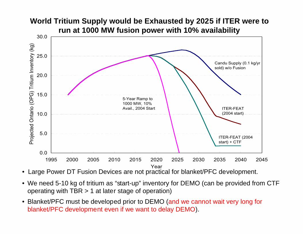
World Tritium Supply would be Exhausted by 2025 if ITER were torun at 1000 MW fusion power with 10% availability
• Large Power DT Fusion Devices are not practical for blanket/PFC development.
• We need 5-10 kg of tritium as “start-up” inventory for DEMO (can be provided from CTFoperating with TBR > 1 at later stage of operation)
• Blanket/PFC must be developed prior to DEMO (and we cannot wait very long forblanket/PFC development even if we want to delay DEMO).

Table S/Z 11
Tritium Supply Calculation Assumptions:• Ontario Power Generation (OPG) has seven of twenty CANDU reactors idled
• Reactors licensed for 40 years
• 1999 tritium recovery rate was 2.1 kg/yr
• Tritium recovery rate will decrease to 1.7 kg/yr in 2005 and remain at this level until 2025
• After 2025 reactors will reach their end-of-life and the tritium recovery rate will decreaserapidly
• OPG sells 0.1 kg/yr to non-ITER/VNS users
• Tritium decays at 5.47 % / yr
• Extending CANDU lifetime to 60 years
It is assumed that the following will NOT happen:
• Restarting idle CANDU’s
• Processing moderator from non-OPG CANDU’s (Quebec, New Brunswick)• Building more CANDU’s
• Obtaining tritium from weapons programs of “nuclear superpowers”
• Irradiating Li targets in commercial reactors (including CANDU’s)
• 15 kg tritium in 1999
(data used in Fig. S/Z 1 for Tritium Supply and Consumption Calculations)
• Premature shutdown of CANDU reactors

Table S/Z 11 (cont’d)
For the ITER-FDR scenario it is assumed:
ITER-FEAT Assumptions:
CTF Assumption:
•Burn 5 kg T/yr for last five years of BPP
•Construction starts in 2004 and lasts 10 years
•There are four years of non-tritium operation
• This is followed by 16 years of tritium operation. The first five years use tritium at alinearly increasing rate reaching 1.08 kg T used per year in the fifth year. Tritiumusage remains at this level for the remainder of tritium operations.
•There is no additional tritium needed to fill materials and systems
•There is no tritium breeding (TBR=0)
•Will burn 1 kg T/yr for ten years (e.g. 120 MW at 30% availability and TBR = 0.5)
•During 2-year install of breeding blanket no tritium burned
•During 10-year EPP will have TBR of 0.8 and require 1.7 kg T/yr from external sources
• Will require about 3 kg T to fill materials and systems (spread over first three years oftritium operations)
•This scenario will not be followed, but is an instructive case study
•Begins burning tritium in 2024
(data used in Fig. S/Z 1 for Tritium Supply and Consumption Calculations cont’d)

Reliability / Maintainability / AvailabilityCritical Development Issues
Unavailability = U(total) = U(scheduled) + U(unscheduled)
Scheduled Outage:
Unscheduled Outage: (This is a very challenging problem)
Planned outage (e.g. scheduled maintenance of components, scheduledreplacement of components, e.g. first wall at the end of life, etc.).
This tends to be manageable because you can plan scheduled maintenance /replacement operations to occur simultaneously in the same time period.
Failures do occur in any engineering system. Since they are random they tendto have the most serious impact on availability.
This is why “reliability/availability analysis,” reliability testing, and“reliability growth” programs are key elements in any engineeringdevelopment.
This you design for This can kill your DEMO and your future

MTBF = mean time between failures = 1/failure rateMTTR = mean time to repair
Notes- Availability analysis generally tries to allocate outage risks and availability to
various components depending on a lot of factors.
- MTTR depends on the complexity and characteristics of the system (e.g.confinement configurations, component blanket design and configuration,nature of failure). Can estimate, but need to demonstrate MTTR in fusion testfacility.
- MTBF depends on reliability of components.
Availability (Unscheduled): Aun= represents a componenti
(Outage Risk) = (failure rate) • (mean time to repair) =i
i
MTBF
MTTRi i
One can estimate what MTBF is NEEDED from “availability allocation models”for a given availability goal and for given (assumed) MTTR.
But predicting what MTBF is ACHIEVEABLE requires real data fromintegrated tests in the fusion environment.
i
1 + ΣΣΣΣ Outage Riski
1

Component Number
Failure rate in hr-1
MTBF in years
MTTR for Major failure, hr
MTTR for Minor failure, hr
Fraction of failures that are Major
Unavailability
Sum of Unavailability
Toroidal Coils
16 5 x10⁻⁶ 23 104 240 0.1 0.098 0.098
Poloidal Coils
8 5 x10⁻⁶ 23 5x10³ 240 0.1 0.025 0.123
Magnet supplies
4 1 x10⁻⁴ 1.14 72 10 0.1 0.007 0.130
Cryogenics 2 2 x10⁻⁴ 0.57 300 24 0.1 0.022 0.152
Blanket 100 1 x10⁻⁵ 11.4 800 100 0.05 0.135 0.287
Divertor 32 2 x10⁻⁵ 5.7 500 200 0.1 0.147 0.434
Htg/CD 4 2 x10⁻⁴ 0.57 500 20 0.3 0.131 0.565
Fueling 1 3 x10⁻⁵ 3.8 72 -- 1.0 0.002 0.567
Tritium System
1 1 x10⁻⁴ 1.14 180 24 0.1 0.005 0.572
Vacuum 3 5 x10⁻⁵ 2.28 72 6 0.1 0.002 0.574
Conventional equipment - instrumentation1, Cooling, turbines, electrical plant ---
0.05 0.624
Assuming 0.2 as a fraction of year scheduled for regular maintenance.Availability = 0.8* (1-0.624) = 0.3
An Example Illustration of Achieving a Demo Availability of 30%(Table from J. Sheffield’s memo to the Dev Path Panel)

Reliability/Availability is a challenge to fusion, particularlyblanket/PFC, development
• There is NO data for blanket/PFC (we do not even know if any present blanketconcept is feasible)
• Estimates using available data from fission and aerospace for unit failure ratesand using the surface area of a tokamak show: probable MTBF for Blanket ~0.01 to 0.2 yr compared to required MTBF of many years
Aggressive “Reliability Growth” Program
We must have an aggressive “reliability growth” program for theblanket (beyond demonstrating engineering feasibility)
1) All new technologies go through a reliability growth program
2) Must be “aggressive” because extrapolation from other technologies(e.g. fission) strongly indicates we have a serious CHALLENGE
• Fusion System has many major components (TFC, PFC, plasma heating,vacuum vessel, blanket, divertor, tritium system, fueling, etc.)
• All systems except the reactor core (blanket/PFC) will have reliability datafrom ITER and other facilities
- Each component is required to have high availability

Upper statistical confidence level as a function of test time in multiples of MTBF for time terminatedreliability tests (Poisson distribution). Results are given for different numbers of failures.
TYPICALTESTSCENARIO
“Reliability Growth”
Example,
To get 80% confidencein achieving a particularvalue for MTBF, thetotal test time neededis about 3 MTBF (forcase with only onefailure occurring duringthe test).
5.04.54.03.53.02.52.01.51.00.50.00.0
0.2
0.4
0.6
0.8
1.0
Test Time in Multiplies of Mean-Time-Between-Failure (MTBF)
Con
fide
nce
Lev
el
Number of Failures 0
1
2
3
4
Reference: M. Abdou et. al., "FINESSE A Study of the Issues, Experiments and Facilities for Fusion NuclearTechnology Research & Development, Chapter 15 (Figure 15.2-2.) Reliability Development Testing Impact on FusionReactor Availability", Interim Report, Vol. IV, PPG-821, UCLA,1984. It originated from A. Coppola, "BayesianReliability Tests are Practical", RADC-TR-81-106, July 1981.

Scenarios for major fusion devicesleading to a DEMO
ITER ⇒ ITER-FEATBPP ⇒ Phase 1EPP ⇒ Phase 2VNS ⇒ CTF
2007 2017 2027 2037 2047 20572000 2010 2020 2030 2040 2050 2060
BPP EPP
Example DEMO Program Plan
I. ITER alone
II. ITER(BPP)+VNS
BPP
VNS
III. ITER(BPP+EPP)+VNSBPP
VNS
EPP
IV. ITER+VNS delayedBPP
VNS
EPP
design operatebuild
Fluence values in MW�yr/m2
0.1
1.1
0.1
3 6 10.5
3 6 10.5
3 6 10.5
1.1
1.1
Schedule backin 1995
Schedule now in2002
Numbers refer to Fluence values in MW•y/m2
Legend for Demo
DesignConstructionOperation

DEMO reactor availability obtainable with 80% confidence fordifferent testing scenarios, MTTR = 1 month
Note: ITER in Scenarios I, III and IV assumes fluence of 1.1 MW•y/m2
(ITER-FEAT 1st phase has 0.1 MW•y/m2)
(Schedule back in1995)(Schedule now in2002)
Calendar year
2013 2017 2021 2025 2029 2033 2037
0.654
0.492
0.360
0.189
20302026202220182014201020060.0
0.1
0.2
0.3
0.4MTTR = 1 month12 test modules
1 failure during the testExperience factor =0.8
This assumes that the divertor hasavailability similar to blanketsystem availability, & thatcombined availability of all othermajor Demo components= 60%
III: ITER +VNS
II: ITER BPP +VNS
IV: ITER +delayed VNS
I: ITER onlyDE
MO
Rea
cto
r A
vaila
bili
ty
Bla
nke
t S
yste
m A
vaila
bili
ty

Recommendations based on Blanket and PFC ReliabilityGrowth Conclusions
• With ITER alone, even at 1 MW•y/m2 fluence (and non-fusion facilitiesand IFMIF), blanket and PFC tests in ITER alone cannot demonstrateblanket system or PFC system availability in DEMO higher than 4%
(This also assumes ITER would be modified to a higher wall loadand to operate with steady state plasma)
• Blanket and PFC testing in VNS (CTF) allows DEMO blanket systemand PFC system availability of ~ 49%, corresponding to DEMOavailability ~ 30%
Note that testing time required to improve reliability becomes even longer athigher availability [e.g. testing time required to increase availability from 30% to50% is much longer than that needed to improve availability to 30%]
- Set availability goal for initial operation of DEMO of ~ 30% (i.e. defer some risk)- Operate CTF and ITER in parallel, together with other facilities, as aggressively
as possible- Realize that there is a serious decision point with serious consequences based
on results from ITER and CTF• If results are positive proceed with DEMO• If not, then we have to go back to the drawing board
Recommendations on Availability/Reliability Growth Strategy and Goals

How About Reliability/Availability of CTF itself?
• CTF needs to be designed as an experimental, flexible, andmaintainable facility
• Must plan an aggressive “Availability Growth” program:- improve maintainability
- “reliability growth” through strategy of test/fail/analyze/fix/improve
- for both test modules and the device itself
• Is it a Challenge?
- Definitely! But, if we do not succeed in CTF in obtaining 25% -30% availability, how can we succeed in DEMO without CTF?
- Blanket/PFC development for DT fusion has high risks. It is moreprudent, less costly, and faster to take these risks with smaller, lessexpensive devices than with large expensive devices
- To put an “untested, unvalidated” breeding blanket on DEMO hasunacceptably high risks, high costs (Impossible?!!). Besides, howwould you call that a DEMO? You should call it CTF.

Component Technology Facility (CTF)
MISSIONMISSION
The mission of CTF is to test, develop, and qualify Fusion NuclearTechnology Components (particularly tritium-breeding blankets)for DEMO. And, to provide data and qualification of plasma-facingcomponents.
The CTF facility will provide the necessary integrated testingenvironment of high neutron and surface fluxes, steady stateplasma (or long pulse with short dwell time), electromagneticfields, large test area and volume, and high neutron fluence.
The testing program and CTF operation will demonstrate theengineering feasibility, provide data on reliability / maintainability /availability, and enable a “reliability growth” development programsufficient to design, construct, and operate blankets, plasmafacing and other FNT components for DEMO.
Note: Shorter mission statements can be written if needed.

Proposed CTF Timeline
Time line for ITER is taken from K. Lackner’s presentation at SOFT, 2002
ITER Construction &Commission
Operation Phase 1a Phase 1b
Operation DT Phase 2
Engineering Design
Design Exploration
Conceptual Design
Construction
Engineering Feasibility
Component Reliability
2005 2010 2015 2020 2025 2030 2035 2040
Design Construct Operate
Demo
CTF

Are there Good Design Options for CTF?
• A key point in the rationale behind CTF is to design a small size,small fusion power (~100 MW), yet achieve a high neutron wallload and steady state plasma operation.
• This can be achieved in MFE by using highly driven plasma(low-Q plasma ~ 1-2).
[Similar idea in IFE is to use low target-yield to lower the fusionpower but make the chamber radius small enough to gethigher wall load]
• Several good options for CTF look attractive.
• Dr. Martin Peng will cover options and issues for a CTF device.

SummarySummary

SummarySummary
A CREDIBLE Plan for DT Fusion Development MUST include aCREDIBLE Plan for Blanket/PFC Development
• The FEASIBILITY, Operability, and Reliability of Blanket/PFC systemscannot be established without testing in fusion facilities
• The fusion testing requirements for blanket/PFC are:- NWL > 1 MW/m2, steady state, test area >10m2, test volume >5 m3
- Fluence Requirements: > 6 MW•y/m2
Engineering Feasibility Phase: 1 – 3 MW•y/m2
(concept performance verification and selection)
Engineering Development & Reliability Growth Phase: >4 MW•y/m2
(not an accumulated fluence on a test article; it is “accumulated test time” onsuccessively improved test articles)
• Tritium Supply considerations are a critical factor in developing acredible strategy for fusion testing and development of blanket/PFC
- The world maximum tritium supply (from CANDU) over the next 40 years is27 kg. This tritium decays at 5.47% per year.
- Remember: A DT facility with 1000 MW fusion power burns tritium at a rate of55.8 kg/yr. Therefore, a large power DT facility must breed its own tritium.
(It is ironic that our major problem is “tritium fuel supply”, while the fundamentalpremise of Fusion is “inexhaustible” energy source)

Options for “Where” to do Blanket/PFC Developmentswere evaluated:
1 – ITER(FEAT): Not Adequate• Low fluence, short plasma burn time/long dwell time, low wall load
do not provide the required capability
2 – MODIFIED ITER: Too Expensive, Too Risky• Requires complete redesign. Very Expensive (Think of ITER-EDA cost
plus more)
• Tritium is not available to run the large-power ITER for high fluence
• For Modified ITER to have its own tritium breeding blanket with TBR ~1is very risky and extremely expensive (building unvalidated blanket over1000 m2 is costly, frequent blanket failures require costly replacements)
3 – DEMO: “Unthinkable”• Deferring Blanket/PFC development until DEMO is “unthinkable” because:
A – All the problems indicated for Modified ITER above (samemistake of doing FNT testing in large power DT device). Plusthere is not much external tritium supply left.
B – This is not a DEMO: a minimum requirement for DEMO is tohave at least one validated concept for each component.
Summary Cont’dSummary Cont’d

So, we have a Serious Problem!
So, what to do?- Think of What Fission Reactor Developers did as an
example:They built small-power testing reactors (10-100 MW), butwith prototypical local conditions.
(They were lucky!!)(They were lucky!!)
- Take advantage of the fact that our good fusion engineershave developed and utilized “engineering scalingengineering scaling” toreduce the FNT testing requirements to 10 MW neutronpower at 1 MW/m2 in only 10 m2 test area (5 m3 testvolume)
Summary Cont’dSummary Cont’d

Attractive Logical Solution
� Build a small size, low-fusion power DT plasma-baseddevice in which Fusion Nuclear Technology experimentscan be performed in the relevant fusion environment atthe smallest possible scale and cost.
- In MFE: small-size, low fusion power can be obtained ina driven low-Q plasma device.
- Equivalent in IFE: Lower target yield and smaller chamberradius.
� This is a faster, much less expensive and less riskyapproach than testing in a large, ignited/high-Q plasmadevice for which tritium consumption, and cost ofoperating to high fluence are very high and the risk istoo great.
Summary Cont�dSummary Cont�d

APPENDIXAPPENDIX
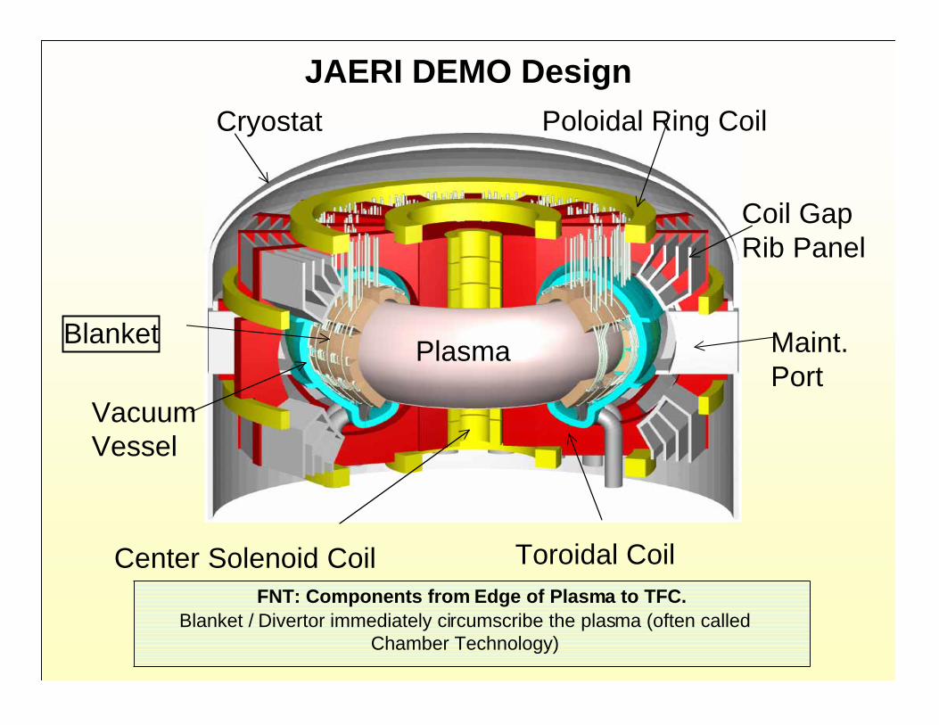
JAERI DEMO DesignCryostat Poloidal Ring Coil
Coil Gap Rib Panel
Blanket
VacuumVessel
Center Solenoid Coil Toroidal Coil
Maint.Port
Plasma
FNT: Components from Edge of Plasma to TFC.Blanket / Divertor immediately circumscribe the plasma (often called
Chamber Technology)

First Wall with embedded Cooling Channels
Breeder and Multiplier Pebble bed layers
Typical Blanket ModuleWeight 4 tonHeight 1 mWidth 2 mThickness 0.6 mNumber of 256modules
Schematic of Test Blanket ModuleFrom Akiba, Japan: Typical Blanket Module in DEMO

A Case Study HICU Project: A High Fluence Irradiation on CeramicBreeder Pebble Beds with Mechanical Constraints in Fission Reactor
Li2O ceramic breeder
Beryllium pebble
Tests for Thermomechanics Interactions of Be/Breeder/He-purge/Structure require “volumetric” heating in complex geometry
(fission then fusion)
Project goals:“the investigation of the impact of neutron spectrum andthe influence of constraint conditions on the thermo-mechanical behavior of breeder pebble-beds in a highfluence irradiation”
Main critical issuesfor the “project”concern the specimensize and thegeometry(limited testvolume in fissionreactor)Instrumentation(neutron dosimeter,thermocouples, tritiummonitor)
Schematic view of pebble-bed assembly,showing cross-section of test-element, second
containment and instrumentation

6 s1 to 5 s
1 to 2 s
~1 s5 to 10 s
30 to 100 s300 to 900 s
20 to 100 s180 to 700 s
30 to 70 s80 to 220 s
10 to 30 s40 to 100 s
150 days10 days
1 to 2 h20 to 30 h
Flow Solid breeder purge residence time Coolant residence time
Thermal Structure conduction (5-mm metallic alloys) Structure bulk temperature rise 5 mm austenitic steel / water coolant 5 mm ferritic steel / helium coolant Solid breeder conduction Li2O (400 to 800ºC) 10 MW/m3
1 MW/m3
LiAlO2 (300 to 1000ºC) 10 MW/m3
1 MW/m3
Solid breeder bulk temperature rise Li2O (400 to 800ºC) 10 MW/m3
1 MW/m3
LiAlO2 (300 to 1000ºC) 10 MW/m3
1 MW/m3
Tritium Diffusion through steel 300ºC 500ºC Release in the breeder Li2O 400 to 800ºC LiAlO2 300 to 1000ºC
Time ConstantProcessTable XX.*Characteristic
Time Constants inSolid Breeder
Blankets
* From Fusion Technology, Vol. 29,pp 1-57, January 1996

Table XXI.*
~30 s~100 s
1 to 2 s~4 s
1 s20 s
4 s300 s
40 days
30 days30 min
2230 days62 days
47 min41 min
Flow Coolant residence time First wall (V=1 m/s) Back of blanket (V=1 cm/s)
Thermal Structure conduction (metallic alloys, 5mm) Structure bulk temperature rise Liquid breeder conduction Lithium Blanket front Blanket back LiPb Blanket front Blanket back
Corrosion Dissolution of iron in lithium
Tritium Release in the breeder Lithium LiPb Diffusion through: Ferritic Steel 300ºC 500ºC Vanadium 500ºC 700ºC
Time ConstantProcess
Characteristic TimeConstants in Liquid-
Metal BreederBlankets
* From Fusion Technology, Vol. 29,pp 1-57, January 1996

• To Achieve DEMO Availability = 48%
97%
90%
R. Buende (1989)
IEA-VNS (1996)
Required BlanketAvailability
• To Achieve DEMO Availability = 30%
J. Sheffield (2002): Required blanket availability = 88%(Assuming Major MTTR = 800 h, Minor MTTR = 100 h)
Required MTBF for DEMO Blanket
Depends on availability requirements and MTTR
75 yr90%48%
60 yr88%30%
Required MTBF for a BlanketModule (100 modules, MTTR=1
month)
Required BlanketAvailability
DEMOAvailability
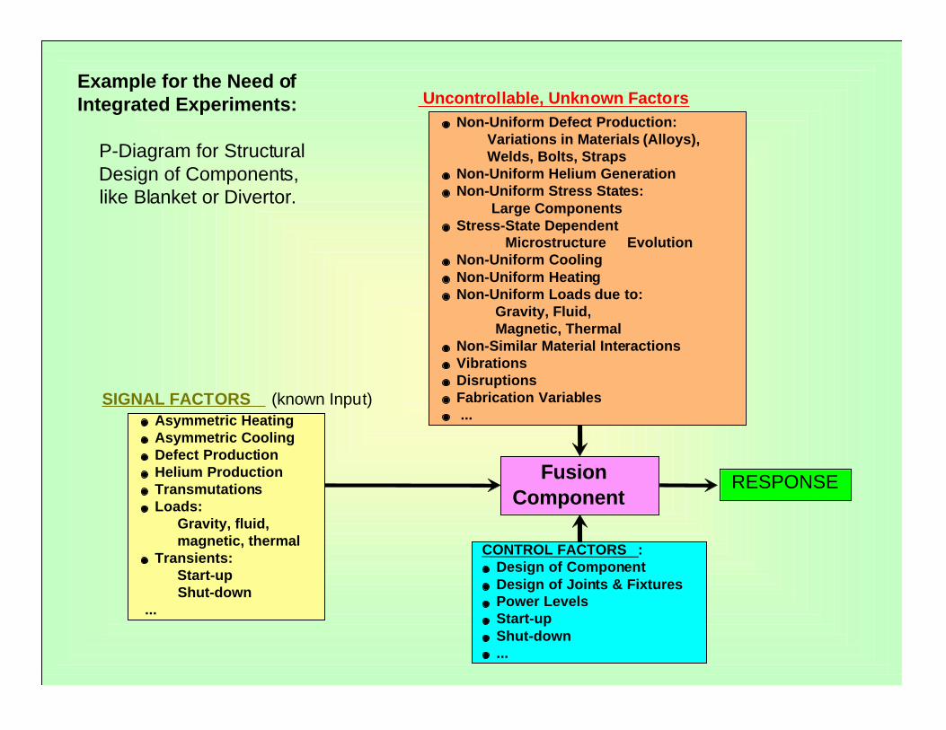
Example for the Need ofIntegrated Experiments:
P-Diagram for Structural Design of Components, like Blanket or Divertor.
Uncontrollable, Unknown Factors
FusionComponent
Asymmetric HeatingAsymmetric CoolingDefect ProductionHelium ProductionTransmutationsLoads:
Gravity, fluid, magnetic, thermal
Transients: Start-up Shut-down ...
RESPONSE
CONTROL FACTORS :Design of ComponentDesign of Joints & FixturesPower LevelsStart-upShut-down...
Non-Uniform Defect Production: Variations in Materials (Alloys), Welds, Bolts, Straps
Non-Uniform Helium GenerationNon-Uniform Stress States:
Large ComponentsStress-State Dependent
Microstructure EvolutionNon-Uniform CoolingNon-Uniform HeatingNon-Uniform Loads due to:
Gravity, Fluid, Magnetic, Thermal
Non-Similar Material InteractionsVibrationsDisruptionsFabrication Variables ...
SIGNAL FACTORS (known Input)

FW-Mock Up Fatigue Testing at FZK
• Thermo-mechanical fatigue test were performed for FW-mock ups from SS 316 L.
– Loading conditions: about 0.7 MW/m2 heat flux (Fig. 1)• The specimens were pre-cracked (notched) perpendicular
to the coolant tubes at different locations with differentsizes (Fig. 2)
• After 75,000 cycles the notched cracks grew to the sizesas indicated.
• However, unexpectedly there were longitudinalcracks that were initiated in every channel - and thesecracks grow under fatigue and would have led tofailure if the experiment continued.
From elastic-plastic fracture mechanics modeling:• Expected the large pre-cracks at the crown of the
channel to fail.• Initiation and growth of the longitudinal cracks were
not and can not be predicted by models.
Fig.1: Schematic of FW-Mock Up
Fig.2:Spark eroded notches and cracks after 75,000 cycles
Fig.3: Crack measurements
Shows an example of unexpected failure modes that cannot be predicted by models.(Information from Eberhard Diegele at FZK)

Max Displacement at Center ~ 7.3 cm with no back support. With back support,these displacements must be accommodated through higher stresses
BC:Bottom and Top Face are FixedNo Rotational Freedom along the back
The Movie shows the displacement at a 1:1 Scale
FW-Panel Displacement:
Effects of 3-D Geometric Features onDisplacement:
FW Central Portion Experiences largest Displacement

Is “Batch” Processing together with “low temperatureblanket” a good “transition” option?
Batch Processing--Evaluated in the 1970s--Conclusion: Not Practical for the “complex” fusion devices
1. In large systems like a tokamak: It takes a long time toremove/reinsert blankets. You still have to go through thevessel, the shield, and the magnet support. (for example:several months in ITER); therefore you cannot do it frequently(once every two years?!).
2. In 1000 MW Fusion Power Device, the tritium consumption is 55.8kg per full power year. So, for 20% availability, tritium inventoryaccumulated in 2 years is >22 kg (in addition to the “hold up”inventories in PFCs and other in-vessel components).
3. Safety experts have suggested much lower targets for tritiuminventory (~2 kg). Note also that tritium will decay at5.47%/year and you will have to provide external start upinventory, plus inventory for duration of “first batch”.
4. And “there is really no effective way to recover tritium from theblanket using a batch process.”
Notes from M. Abdou and D. Sze in response to a question received on 10/25/2002.

Low-Temperature Blanket?
Evaluated during INTOR, ITER-CDA, ITER-EDA
Assessment:
-- It is still high risk because we use technologiesunvalidated in the fusion environment.
-- There is no good low-temperature breeding blanketoption. You can have only “partly” low-temperature.
-- “Partly” low-temperature breeding blankets have theiradded complications and issues for which an additionalR&D program is needed.

Options for Low-Temperature Blanket?
• All self-cooled liquid metal options require hightemperature (>300°C) because of high melting point. Wedo not know if any of them are feasible in the fusionenvironment because of issues such as insulators, tritiumbarriers, etc.
• Separately-cooled LiPb requires either Helium or water,both above 300°C. Practically all feasibility issues for“reactor-type” blankets are the same and must beresolved by extensive testing first in the fusionenvironment.

Options for Low-Temperature Blanket? (cont’d)
•Solid Breeder Options were evaluated in INTOR, and ITER-CDA, ITER-EDA
-- Breeder must run at high temperature
-- Only the coolant can be low temperature
-- All the feasibility issues with thebreeder and multiplier are essentiallythe same as those for reactor-typeblanket. But with the added complexityof providing “thermal resistance”between the low-temperature coolantand the hot solid breeder.
-- Both stainless steel and ferritic steelhave severe embrittlement problems atlow-temperature (ITER can use low-temperature coolant in the present non-breeding design only because of thevery low fluence).
Plasma
Breeder pebblebed rod
Beryllium pebble bedis used as atemperature barrier ina low temperaturebreeding blanketdesign