of a coilable lattice column · investigation of a coilable lattice column ... the design concept...
TRANSCRIPT
C O N T R A C T O R
R E P O R T
INVESTIGATION OF A COILABLE LATTICE COLUMN
by R. F. Crdwford
Prepared by
ASTRO RESEARCH CORPORATION
Santa Barbara, Calif.
for
N A T I O N A L A E R O N A U T I C S A N D S P A C E A D M I N I S T R A T I O N W A S H I N G T O N , D. C. M A Y 1 9 6 9
https://ntrs.nasa.gov/search.jsp?R=19690016856 2018-08-27T01:13:25+00:00Z
TECH LIBRARY KAFB, NM
NASA CR-1301
INVESTIGATION OF
A COILABLE LATTICE COLUMN
By R. F. Crawford
Distribution of this report is provided in the interest of information exchange. Responsibility for the contents resides in the author or organization that prepared it.
Issued by Originator as Report No. ARC-R-310
Prepared under Contract No. NAS 7-427 by ASTRO RESEARCH CORPORATION
Santa Barbara, Calif.
for
NATIONAL AERONAUTICS AND SPACE ADMINISTRATION
Far sale by the Clearinghouse far Federal Scientific and Technical Information Springfield, Virginia 22151 - CFSTI price $3.00
INTRODUCTION AND SUMMARY
A l a t t i c e column c o n s i s t i n g o f s i x longerons interconnected b y c r o s s e d h e l i c a l b r a c e s was f a b r i c a t e d a n d t e s t e d t o d e t e r m i n e t h e f e a s i b i l i t y o f i t s c o n c e p t a n d t o v e r i f y a n a l y s i s o f i t s s t ruc tu ra l pe r fo rmance . I t s h e l i c a l braces form a c ross - sect ional shape which can be e l a s t i c a l l y f l a t t e n e d . T h i s f l a t - t ened column can then be c o i l e d l o n g i t u d i n a l l y i n t o a r e l a t i v e l y s m a l l c y l i n d r i c a l volume.
The t e s t segment of the column was fabricated of 0 .035-inch diameter s t e e l wires jo ined toge ther wi th "co ins" in to which the i n t e r s e c t i o n o f t h e w i r e s was so ldered . Tests were performed on the segment to de te rmine i t s t o r s i o n a l s t i f f n e s s , a x i a l b u c k l i n g s t r e n g t h , a n d i t s c a p a b i l i t y t o be f l a t t e n e d a n d c o i l e d .
Fo l lowing a r e t he r e s u l t s of the tests:
1. The method used t o f a b r i c a t e t h e t e s t segment produced a s a t i s f a c t o r y model f o r t h i s e x p l o r a t o r y i n v e s t i g a t i o n ; h o w e v e r , o the r f ab r i ca t ion me thods may prove t o b e more p r a c t i c a b l e .
2. The r e s u l t s o f s e v e r a l t o r s i o n a l s t i f f n e s s tests o f t h e column compared w e l l w i t h a t h e o r e t i c a l v a l u e o f 1 2 7 5 l b - i n . 2 Local buckl ing of t h e longerons of t h e column o c c u r r e d a t a load of 1 2 pounds. T h i s buckl ing load i s 1 . 7 2 times t h e E u l e r load fo r l onge rons whose e n d s a re h inged . The he l i ca l b races s t ab i l - i zed t h e longe rons o f t he p re sen t t e s t segment.
The agreement between theoretical and experimental values of t o r s i o n a l s t i f f n e s s and buckling load i s c o n s i d e r e d s a t i s f a c - t o r y f o r p r e s e n t p u r p o s e s .
LIST OF SYMBOLS
A, B, C, D, and E
E1
GJEXP
-THEOR
H
h
K
P CR
C P cR&
Q
Coefficients of terms in complete solution to differential equation
Diameters of brace and longeron elements, respectively
Bending stiffness of either longeron or brace elements
Experimentally determined torsional stiff- ness of column
Theoretically determined torsional stiff- ness of column
Amplitude of initial shape of brace elements
Distance between intersections of brace elements
Coefficient in Eq. (15); accounts for effect of braces in stabilizing longerons against local buckling.
Column length
Length of longeron elements between inter- sections
Internal moment in brace at any position
Moment required to prevent rotation of one end of brace
Critical buckling load of column
Critical buckling load of one longeron
Axial load in brace due to torsion of column
*EU Euler buckling load of brace
2
I "
QCR
R C
R P
S
T
V
- X
YO
yQ
U
h
6
6V
9
'b C
C r i t i c a l b u c k l i n g l o a d o f brace
Top v i e w r a d i i o f column cross s e c t i o n
Packaged radius t o which the column i s c o i l e d
S t i f f n e s s o f b r a c e s u n d e r a x i a l l o a d i n g , Q
R o t a t i o n a l s t i f f n e s s w h i c h t h e b r a c e s p r o - v i d e i n s t a b i l i z i n g t h e l o n g e r o n s a g a i n s t buck l ing
T o r q u e a p p l i e d t o column
I n t e r n a l r e a c t i o n f o r c e i n column due t o app l i ed t o rque
Coordinate axes f o r s t i f f n e s s a n a l y s i s of b r a c e s
Normalized coordinate , x = - h - X
I n i t i a l shape of he l ica l b race
Change i n shape of brace due t o a p p l i c a t i o n o f a x i a l l o a d , Q
Hel ix angle o f b races
Parameter , l 2 = Q E1
N e t r e l a t ive end d i sp l acemen t o f b race
End d i s p l a c e m e n t o f b r a c e i n d i r e c t i o n o f f o r c e , V
T w i s t o f co lumn per un i t l ength due to a p p l i e d t o r q u e , T
Direct s t r a i n i n brace d u e t o c o i l i n g o f column
3

€
bf
% s
ybf
'b C
Direct s t r a i n i n brace due t o f l a t t e n i n g t h e column
Direct s t r a i n i n l o n g e r o n d u e t o c o i l i n g t h e column
S h e a r i n g s t r a i n p r o d u c e d i n a brace due t o f l a t t e n i n g t h e column
S h e a r i n g s t r a i n p r o d u c e d i n a brace due t o c o i l i n g t h e column
4

DESIGN CONCEPT
The des ign concept fo r t h i s coilable l a t t i c e column is i l l u s - t r a t e d b y F i g u r e 1. Longerons are the p r imary load-car ry ing mem- bers of t h e s t r u c t u r e . T h e f u n c t i o n s o f t h e h e l i c a l braces are to i n t e rconnec t , dep loy , and s t a b i l i z e the longerons and t o pro- v i d e t h e c o m p o s i t e s t r u c t u r e w i t h s h e a r i n g a n d t o r s i o n a l s t i f f n e s s . The p a r t i c u l a r number of longe rons and t he he l ix ang le of t h e braces shown i n F i g u r e 1 are not germane t o the concep t : t hey can be o p t i m i z e d i n f u t u r e d e s i g n s t u d i e s . T h e braces are formed of c i r c u l a r arcs o f equa l r ad i i , a s sembled i n t he fo rm shown, so t h a t t h e m a x i m u m no rma l and shea r ing s t r a ins i n t he ba t t ens r e s u l t i n g f r o m f l a t t e n i n g t h e column are l i m i t e d t o
db 2 € = + - cos a bf - 2R
C
d h
ybf = + ? s i n a cosu - 2R
C
When t h e f l a t t e n e d column is t h e n c o i l e d i n t o a c y l i n d r i c a l c o n f i g u r a t i o n , t h e maximum s t r a i n s i n t h e longe rons a r e
dt € = + - 4 - 2 R
P
T h i s c o i l i n g w i l l p roduce add i t iona l no rma l and shea r ing s t r a ins i n t h e braces, t h e m a x i m u m v a l u e s of which are
db 2 8 = + - s i n a
P b - 2R
C
5

The s t r u c t u r a l d i m e n s i o n s t o be u s e d f o r t h i s t y p e of column w i l l depend upon t h e e las t ic s t r a i n l i m i t a t i o n s of i t s material , t h e s t r u c t u r a l capab i l i t i e s r e q u i r e d of it, and package s ize l i m i t a t i o n s .
6
TEST SEGMENT
S i n c e t h e o b j e c t i v e o f t h e p r e s e n t i n v e s t i g a t i o n is t o d e t e r - mine f e a s i b i l i t y o f t h e c o n c e p t and i t s mechanica l p roper t ies , t h e p r o p o r t i o n s of t h e t es t segment w e r e selected on ly from .
c o n s i d e r a t i o n s of fabr ica t ion convenience and the requi rement t h a t t h e cross s e c t i o n be f l a t t enab le w i thou t exceed ing t he e las t ic s t r a i n l i m i t of t h e brace m a t e r i a l .
A photograph of t h e test segment is shown i n F i g u r e 2. Both the l onge rons and he l i ca l b races were f a b r i c a t e d f r o m 0.035-inch diameter s teel music w i r e , which conforms t o MIL-6101 and QQ-W- 470-A. The y i e l d s t r e n g t h o f t h e w i r e is approximately 165 000
p s i , and i ts modulus was determined as 2 8 x 10 psi . Following is a summary of the dimensions of t h e t es t segment.
6
L = 20.9 i n .
4, = 4.18 i n .
R = 2.00 i n . C
d4, = db = 0.035 i n .
a = n/4 rad
The h e l i c a l s e c t i o n s w e r e b e n t t o the requi red 4 - inch rad ius p r i o r t o a s s e m b l i n g t h e column. The ends of the w i r e s were then i n s e r t e d i n t o t h e c o i n s on an assembly j i g , where t hey were so lde red i n p l ace .
The c o i n - l i k e i n t e r s e c t i o n f i t t i n g s shown i n F i g u r e 3 were made o f b r a s s . A s i n d i c a t e d , t h e h o l e s i n t h e t h i n n e r c o i n s u s e d f o r j o i n i n g l o n g e r o n i n t e r s e c t i o n s a r e c o p l a n a r t o avoid eccen- t r ic i t i es .
The h o l e s i n t h e t h i c k e r co ins could no t be coplanar . How- e v e r , e c c e n t r i c i t i e s i n t h e s e c o i n s , w h i c h o n l y c o n n e c t h e l i c a l m e m b e r s a l o n g t h e co lumn edges , a re no t de t r imenta l .
7
End plates for distributing the applied axial and torsional loads to the members of the column were attached by short wire segments, as indicated in Figure 2.
8
TEST PROCEDURE AND RESULTS
Torsion Test
T o r s i o n a l s t i f f n e s s tests were performed i n a n a p p a r a t u s which is shown s c h e m a t i c a l l y i n F i g u r e 4. The r e s u l t i n g t o r q u e - t w i s t d a t a a r e shown i n F igure 5. Non l inea r i ty and s ca t t e r is n o t e d t o e x i s t i n t h e d a t a . The nonl inear i ty appeared t o be e l a s t i c . b e c a u s e no permanent deformations were o b s e r v e d t o r e s u l t from t h e tests. Dur ing appl ica t ion of the t o rques , t he l onge rons remained unbent . The hel ical braces underwent increases and d e c r e a s e s i n t h e i r r a d i i o f c u r v a t u r e , d e p e n d i n g o n t h e i r c u r v a - t u r e and on whether they w e r e i n t h e d i r e c t i o n s t o resist t h e appl ied torque by compression or tension.
The s c a t t e r among t h e v a r i o u s t o r s i o n tes ts shown i n F i g u r e 5 was due, a t l e a s t p a r t i a l l y , t o v a r i a b l e f r i c t i o n i n t h e t e s t a p p a r a t u s . T h e i n i t i a l s l o p e o f t h e l o w e s t t es t r u n g i v e s t h e f o l l o w i n g v a l u e o f t h e t o r s i o n a l s t i f f n e s s of t h e column:
2 1100 lb- in .
Buckling Test
The t es t segment was ax ia l ly compressed as shown by the photograph o f t h e appara tus (F ig . 6 ) . S p h e r i c a l b a l l s between t h e segment and t h e loading appara tus e n s u r e d uniform loading of t h e longerons. Weights were placed on the loading pan of t h e appara tus i n one-pound increments unt i l buckl ing was observed. The t e s t appa ra tus w a s a d j u s t e d p r i o r t o t h e t es t such t h a t t h e loading pan could t rave l on ly 1/16 inch when buckl ing occur red . Bending of the longerons d u e t o buck l ing was t h u s r e s t r i c t e d , a s i s e v i d e n t i n F i g u r e 6, and r e s u l t e d i n no permanent deformations.
The c r i t i c a l l o a d f o r b u c k l i n g i n t h e mode shown i n F i g u r e 6, t h e o n l y mode observed, was 1 2 pounds. The buckling mode was pre- dominantely one in which t h e i n t e r s e c t i o n s o f t h e l o n g e r o n s remained undef lec ted and the longerons d i sp laced rad ia l ly inward and outward between intersect ions, i .e. , l oca l Eu le r buck l ing o f t h e l o n g e r o n s . T h e b r a c e s r e s t r a i n e d r o t a t i o n of the l onge ron i n t e r s e c t i o n s , as i s clear f r o m t h e a n a l y s i s o f t h e d a t a g i v e n la ter i n t h i s report.
9
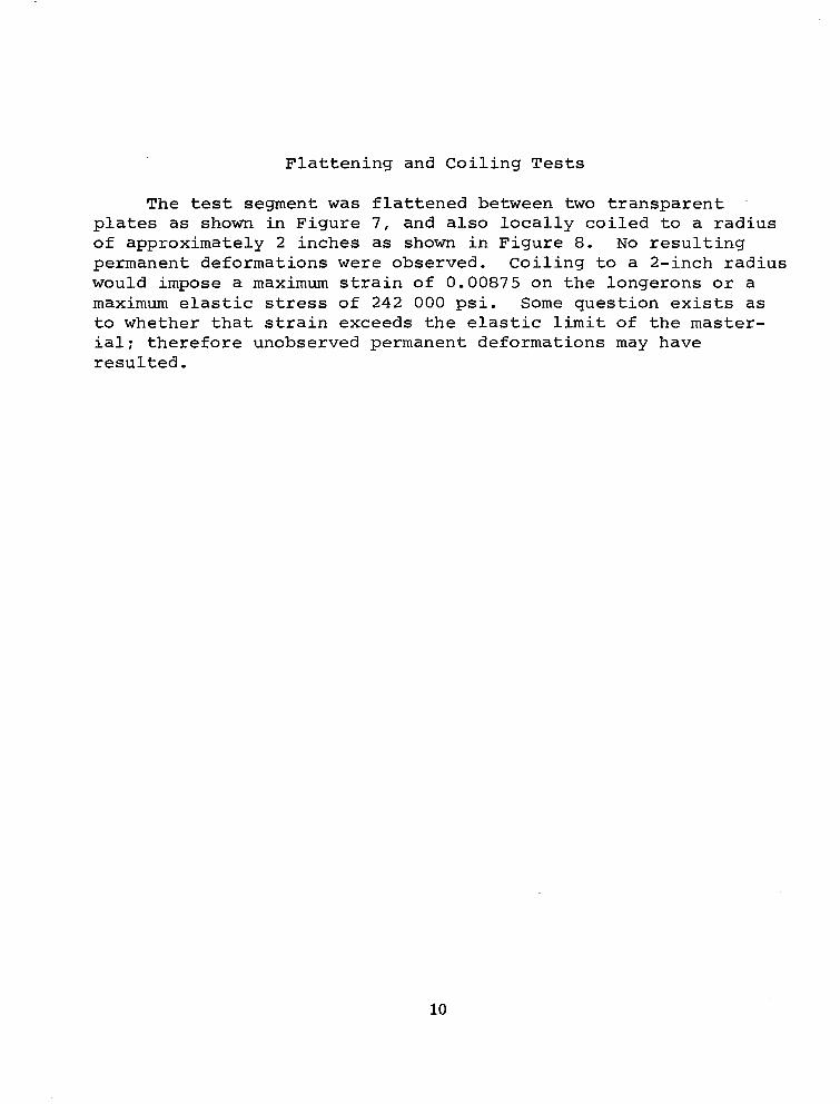
F l a t t e n i n g and C o i l i n g T e s t s
The t e s t segment w a s f l a t t ened be tween two t r a n s p a r e n t -
plates as shown i n F i g u r e 7 , and a l s o l o c a l l y c o i l e d t o a r a d i u s of approximately 2 i nches as shown i n F i g u r e 8. N o r e s u l t i n g permanent deformations w e r e obse rved . Co i l ing t o a 2- inch radius would impose a m a x i m u m s t r a i n o f 0.00875 on t he l onge rons o r a m a x i m u m e las t ic stress of 242 000 ps i . Some q u e s t i o n exists a s t o w h e t h e r t h a t s t r a i n e x c e e d s t h e e las t ic l i m i t of t h e master- i a l ; therefore unobserved permanent deformations may have r e s u l t e d .
10

ANALYSIS OF MECHANICAL BMAVIOR
T o r s i o n a l S t i f f n e s s
Torque acting on the column may be reac ted by forces , 2V , a c t i n g a t f o u r t y p i c a l i n t e r s e c t i o n s of t h e h e l i c a l b r a c e s and i n t h e d i r e c t i o n s o f s t r a i g h t l i n e s b e t w e e n t h e e n d s o f t h e braces, a s shown i n F i g u r e 9. The torque is t h e n r e l a t e d t o t h e r e a c t i o n f o r c e s b y .
T = 4 6 V R C
Forces , Q , d i r e c t e d a l o n g s t r a i g h t l i n e s b e t w e e n t h e ends of t h e h e l i c a l s e g m e n t s e q u i l i b r a t e t h e i n t e r s e c t i o n f o r c e s a c c o r d i n g t o
v Q = -
c o s a
The forces on the he l i ca l s egmen t s a r e compress ion i n one ha l f and tension i n t h e o t h e r .
The a x i a l s t i f f n e s s o f t h e b r a c e s is der ived i n the Appendix as fo l lows fo r va lues o f Q very much s m a l l e r t h a n t h a t f o r E u l e r buck l ing o f t he b races :
Q 5 E 1
H h 2
"- -
I n t h i s e q u a t i o n 6 is t h e r e l a t i v e d i s p l a c e m e n t of the ends of a b r a c e when ac t ed upon by f o r c e , Q ; E1 i s the bending s t i f f - ness o f t he brace; H i s the ampl i tude of t h e i n i t i a l s h a p e ( c i r c u l a r ) of the brace; and h i s the d i s t ance be tween t he ends of one brace element.
11

For t h e t e s t segment,
R
cosa c h = -
and t he he igh t s of t h e c i r c u l a r a . r c s be tween i n t e r s e c t i o n s a r e expressed as
I n t h e A p p e n d i x , t h e c i r c u l a r a r c s h a p e of t h e b r a c e was approx- imated a s a segment of a parabola of t h e same a rc he igh t .
Displacements i n t h e d i r e c t i o n of f o r c e s , V , a r e r e l a t e d t o t h o s e i n t h e ' d i r e c t i o n o f f o r c e s , Q , by
6 'V cosa " -
And, t h e t w i s t of the column, 9 , p e r u n i t l eng th i s r e l a t e d t o 6, by
3 hV e = "I
I-T R t a n a cos3Oo L
C
B y combining Equations ( 6 ) through ( 1 2 ) , t h e t o r s i o n a l s t i f f n e s s of the column, G J , i s found a s
T - " - - lor EI cos 2 a s i n u G J ~ ~ ~ ~ ~ . 8 (o.134)2
12
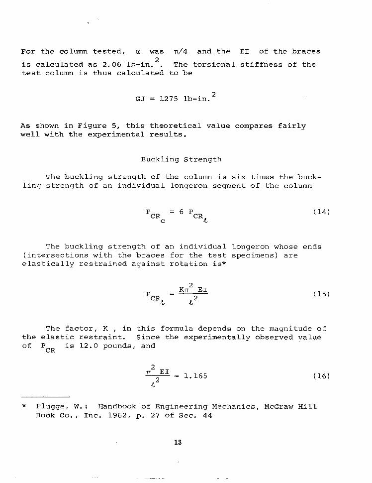
For the co lumn tes ted , a was n/4 and the E1 of the braces
is c a l c u l a t e d a s 2.06 lb-in. . The t o r s i o n a l s t i f f n e s s o f t h e t e s t column is t h u s c a l c u l a t e d t o be
2
GJ = 1275 lb-in. 2
As shown i n F i g u r e 5, t h i s t h e o r e t i c a l value compares f a i r l y w e l l w i t h t h e e x p e r i m e n t a l r e s u l t s .
Buckl ing Strength
The buck l ing s t r eng th o f t he column i s s i x t i m e s the buck- l i n g s t r e n g t h of an individual longeron segment of the column
P - CR - PCR
C .e
The b u c k l i n g s t r e n g t h o f a n i n d i v i d u a l ( i n t e r s e c t i o n s w i t h t h e b r a c e s f o r t h e t es t e l a s t i c a l l y r e s t r a i n e d a g a i n s t r o t a t i o n is*
KIT E1 2
P - - cR& d2
longeron whose specimens) are
ends
The f a c t o r , K , i n t h i s fo rmula depends on the magnitude of t h e e l a s t i c r e s t r a i n t . S i n c e t h e e x p e r i m e n t a l l y o b s e r v e d v a l u e of P i s 12.0 pounds, and
CR
n2 E 1 = 1.165
-t2
* Flugge, W. : Handbook of Engineering Mechanics, McGraw H i l l Book Co. , Inc. 1962, p. 27 of Sec. 44
13

fo r the l onge rons of t h e t e s t segment, then
K = 1.72
This va lue of K corresponds* t o a longeron end r e s t r a i n t a g a i n s t r o t a t i o n of 0.271 in . - lb / r ad , appa ren t ly p rov ided by t he he l i ca l b races .
* I b i d . page 13
14
CONCLUSIONS
T h i s i n v e s t i g a t i o n h a s shown t h a t t h e c o n c e p t o f a c o i i a b l e l a t t i c e column is e n t i r e l y f e a s i b l e . F u r t h e r t h e o r e t i c a l and exper imenta l inves t iga t ions should be per formed t o d e f i n e t h e mos t su i t ab le p ropor t ions a s t hey w i l l vary with loading index, packaging requirements, and m a t e r i a l c a p a b i l i t i e s .
The c o r r e l a t i o n o b t a i n e d between experimental and t h e o r e t i c a l va lues of b o t h t o r s i o n a l s t i f f n e s s and b u c k l i n g s t r e n g t h is con- sidered t o be s a t i s f a c t o r y e v i d e n c e t h a t t h e m e c h a n i c s o f t h i s concept a re unders tood .
15

I R
t ive
Figure 1. Design Concept of a C o i l a b l e L a t t i c e Column
16

Figure 2. Test Segment of a Coilable Lattice Column
I
l 17

( t y p i c a l ) .05;
a . C o i n f o r j o i n i n g i n t e r s e c t i o n s of longerons and h e l i c a l b r a c e s
0.188 i n .
\
0.036 in. diam. ( t y p i c a l )
b. Coin for joining braces a long edge of column where no longerons a re p resent
F igu re 3 . "Co ins" fo r Jo in ing Members of Test Segment
18
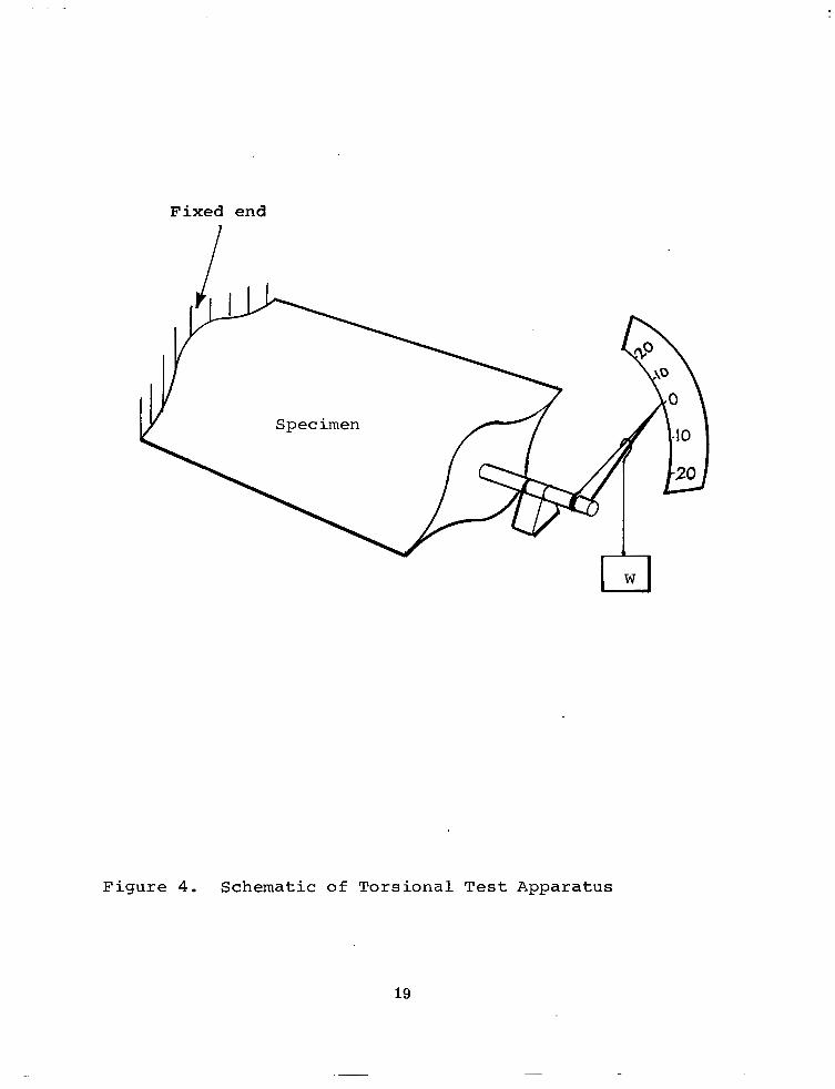
Fixed end
Specimen
F i g u r e 4. Schematic of T o r s i o n a l Test Apparatus
19

20
1 6
h
21 2
0
I I I X T e s t N o . 1
0 T e s t N o . 2
A T e s t N o . 3 - _ _ _ T h e o r e t i c a l l y p r e d i c t e d t o r q u e v e r s u s t w i s t
I
2 4 6 8 10 12 14 16
T o t a l c o l u m n t w i s t ( d e s )
F i g u r e 5. E x p e r i m e n t a l V a l u e s of T o r q u e v e r s u s T w i s t f o r T h r e e D i f f e ren t Tests C o m p a r e d w i t h T h e o r e t i c a l Values
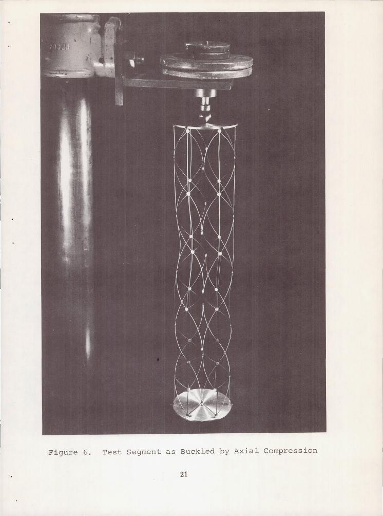
Figure 6. Test Segment as Buckled by Axial Compression
21

Figure 7. Test Segment in Flattened Configuration
22
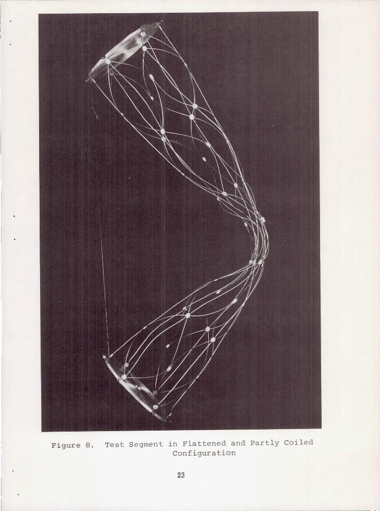
Figure 8. Test Segment in Flattened and Partly Coiled Configuration
23

Repea
B r a c e s f o r c e s
"
t i n g e l e m e n t o f column w i t h j o i n t f o r c e s
F i g u r e 9. Schematics of Column under Applied Torque and I n t e r n a l R e a c t i o n s
24

APPENDIX
AXIAL STIFFNESS OF BRACES
When to rque is app l i ed t o t h e column, t h e braces w h i c h h e l i x i n o n e d i r e c t i o n w i l l be compressed whi le those which he l ix in t h e o t h e r w i l l be tens ioned . S ince the shape of t h e h e l i c a l b races be tween i n t e r sec t ions is c i r c u l a r , t h e y w i l l bend i n r e a c t i o n t o t h e s e t e n s i l e and compressive forces, tending t o a m p l i f y t h e i n i t i a l r a d i a l d e f l e c t i o n s when compressed, and t o d iminish them when tens ioned . I t i s the purpose of t h e p r e s e n t a n a l y s i s t o d e t e r m i n e t h e e f f e c t i v e a x i a l s t i f f n e s s of t h e braces under these condi t ions .
The r a d i a l d e f l e c t i o n s o f e a c h se t o f h e l i c a l b r a c e s , t h o s e tens ioned or those compressed , w i l l be symmetric about t h e i r i n t e r s e c t i o n s w i t h the center longerons and about column-edge i n t e r s e c t i o n s . The def lect ions, however , w i l l be asymmetric a b o u t t h e i r i n t e r s e c t i o n s w i t h t h e s i d e longerons. Therefore , the boundary condi t ions used in the fo l lowing ana lys i s of a s ing le brace segment a re t h a t one end i s f ixed and t h e o t h e r i s f r e e t o r o t a t e . I t is assumed t h a t t h e r e is no r a d i a l d i s p l a c e - m e n t o f t h e i n t e r s e c t i o n s b e c a u s e r a d i a l c o m p o n e n t s o f t h e t e n s i l e a n d c o m p r e s s i v e f o r c e s i n t h e b r a c e a r e n u l l a t t h e i r i n t e r - s e c t i o n s .
The a x i a l s t i f f n e s s of t h e h e l i c a l b r a c e s is t h e r e f o r e analyzed in accordance with the fol lowing sketch
Y = d e f l e c t i o n f r o m i n i t i a l
A
f
= i n i t i a l s h a p e
Q- 1
0 \ Q- x h
25
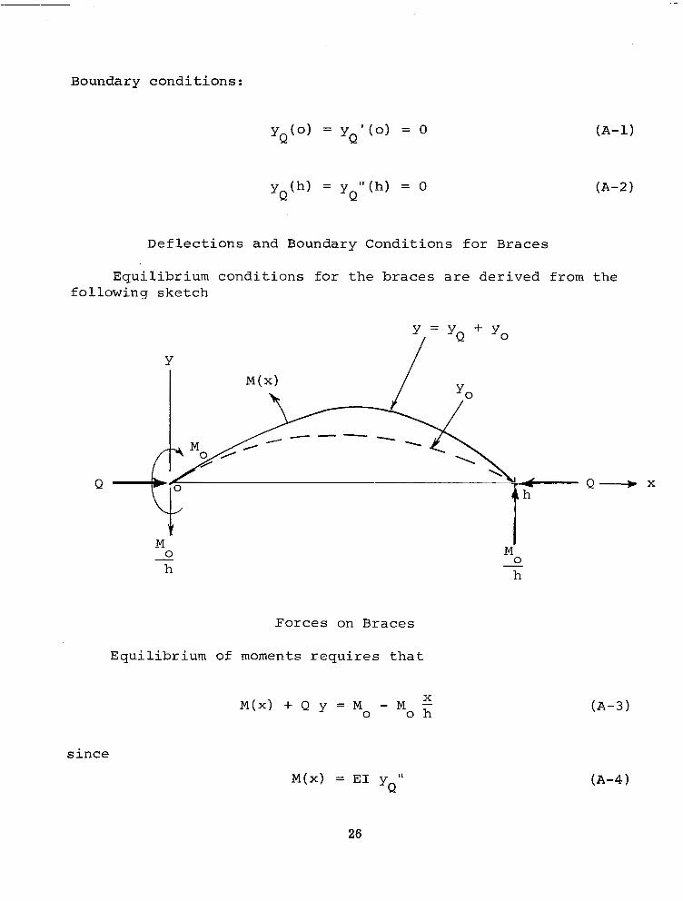
Boundary conditions:
YQ(0) = y ' ( 0 ) = 0 Q (A -1 )
y (h ) = y " ( h ) = 0 Q Q (A -2 )
Deflec t ions and Boundary Condi t ions for Braces
Equ i l ib r ium cond i t ions fo r t he b races a r e de r ived f rom the fo l lowing ske tch
Y
Q
Forces on Braces
Equi l ibr ium of moments r e q u i r e s t h a t
M ( x ) + Q y = M x
0 - Mo h
s i n c e
M ( x ) = E1 yQl'
26
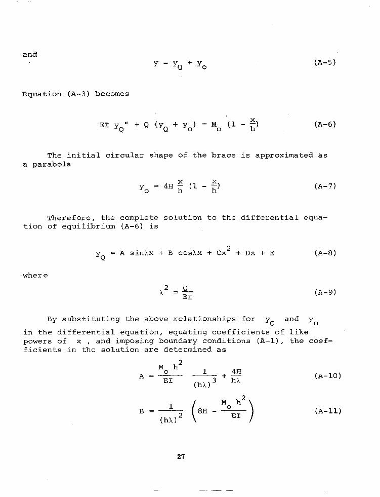
and Y = YQ + Yo
Equat ion ( A - 3 ) becomes
The i n i t i a l c i r c u l a r s h a p e o f t h e b r a c e i s approximated as a parabola
T h e r e f o r e , t h e c o m p l e t e s o l u t i o n t o t h e d i f f e r e n t i a l equa- t i o n of equi l ibr ium (A -6 ) i s
yQ = A s i n l x + B c o s ~ x + cx2 + DX + E
where
1 2 Q = - E1
B y s u b s t i t u t i n g t h e above r e l a t ionsh ips fo r and yQ YO
i n t h e d i f f e r e n t i a l e q u a t i o n , e q u a t i n g c o e f f i c i e n t s o f l i k e powers of x , and imposing boundary conditions ( A - l ) , the coef - f i c i e n t s i n t h e s o l u t i o n a r e d e t e r m i n e d a s
0
Md hL 1 4 N
(hXI3 hX + - A =
1
(hX) * B = (*H -
(A-10)
(A -11 )
27
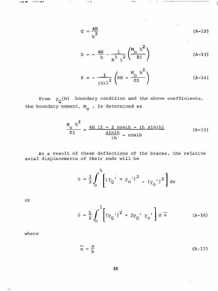
4H c = - h2
(A-12)
(A-13)
(A- 14)
From yQ(h) boundary condi t ion and the above coef f ic ien ts ,
the boundary moment, M i s de te rmined a s 0 ,
E1 ( A - 1 5 )
A s a r e s u l t o f t h e s e d e f l e c t i o n s o f t h e braces, t h e r e l a t i v e ax ia l d i sp lacements o f the i r ends w i l l be
h
or
(A- 16)
where
- X x = - h
28
(A-17)
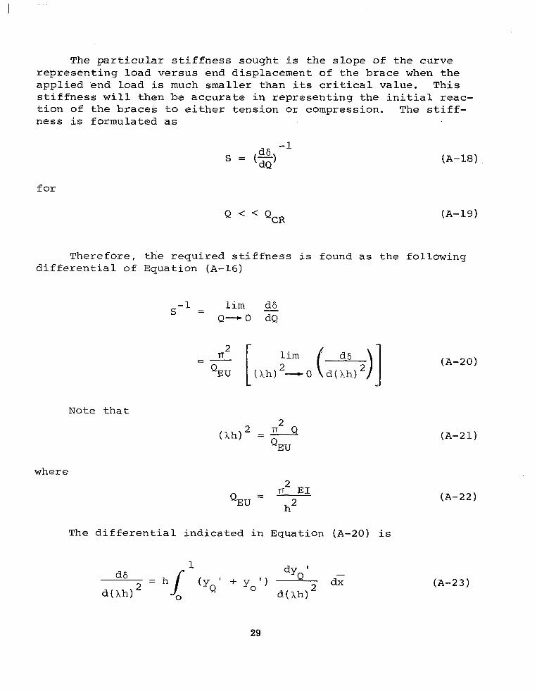
The p a r t i c u l a r s t i f f n e s s s o u g h t i s t h e s l o p e of t h e curve represent ing load versus end d i sp lacement o f the b race when t h e appl ied end load is much smal le r than i t s c r i t i c a l v a l u e . T h i s s t i f f n e s s w i l l then be a c c u r a t e i n r e p r e s e n t i n g t h e i n i t i a l r e a c - t i o n o f t h e b r a c e s t o e i t h e r t e n s i o n o r c o m p r e s s i o n . The s t i f f - nes s i s fo rmula t ed a s
d6 dQ
-1 s = (-) (A-18)
f o r
Q < < Q,, (A-19)
T h e r e f o r e , t h e r e q u i r e d s t i f f n e s s i s found a s t h e f o l l o w i n g d i f f e r e n t i a l of Equation (A-16)
-1 lim 3 s = Q-0 dQ
Note t h a t 2
= - T Q
QEU
where
- n2 E 1 QEU
- h2
The d i f f e r e n t i a l i n d i c a t e d i n Equation (A-20) i s
(A-20)
( A - 2 1 )
( A - 2 2 )
(A-23)
29

2 The limits as (Ah) - 0 o f t h e d e r i v a t i v e s i n d i c a t e d i n
Equation (A-23) w e r e eva lua ted a s fo l lows f rom the foregoing s o l u t i o n o f t h e e q u i l i b r i u m equat ion:
1 i m
' (Xh)2-0 Y Q ' = 0
and
1 i m H - 5 - 4 - 2 2 2 h 2 3 x + - x
(Ah) - 0 d(Ah)
The d e r i v a t i v e of ' i s simply YO
4 H h " - (1 - 2 5
(A-24)
(A-2 5 )
(A-26)
' Therefore , S i s found by pe r fo rming t he r equ i r ed i n t eg ra t ion a s
5 E1 s = - H h
2
30
( A - 2 7 )
NASA-Langley, 1969 - 32 CR-1301