oem products - doepfer musikelektronik gmbh
TRANSCRIPT

DOEPFERDOEPFERDOEPFER2010-012010-012010-01
www.doepfer.com
OEM PRODUCTSOEM PRODUCTS

DOEPFER MUSIKELEKTRONIK GMBHGeigerstr. 13 D-82166 Graefelfing / Germany Phone 089-89 80 95 10 Fax 089-89 80 95 11
www.doepfer.com [email protected]
This catalogue shows all our OEM products that areavailable at present. is the abbreviaton of
. An OEM product isnot a ready-made device but a DIY ( o t ourself) kitthat has to be completed by the customer to obtain aworking unit. An OEM product cannot be usedindependently but has to be combined with additionalelectrical or electronical equipment to become aworking device (e.g. rotary or fader potentiometers,rotary encoders, buttons, LEDs, keyboard, pitch bendor modulation wheel, power supply, case/housing andso on).
circle offriends who can help you
The manufacturer of an OEM product does not knowthe final assembly of the complete device in whichthe OEM product is used as a part of the completedevice. The final responsibility with regard toelectrical safety and electromagnetic compatibility isup to the user who is assembling the completedevice. On all our OEM products
against aremet (e.g. RF filters at the power supply input and theMIDI lines). But it is impossible to estimate to whatextend the affectthe of the complete assembly.Therefore the has to beagainst (incoming andoutgoing) These demands are normally met by aclosed metal case that covers the completeassembly. The metal case should be connected toGND of the device in question.
Our OEM/DIY products can be used to built your ownunique midi controller (keyboard 2/3/4/5 octaves +rotary potentiometers + faders + switches + rotaryencoders) or midi controlled switches (lamps, relays,magnets, motors, LEDs ....).
OEMoriginal equipment manufacturer
d i y
preventingmeasures electromagnetic radiation
components added by the userEMC properties
complete device shieldedelectromagnetic radiation
.
Electronic basic knowledge is required to operateand install an OEM product. For example severalcontrolling elements - like potentiometers,buttons, LEDs and similar - have to be added bythe customer and the complete construction hasto be assembled into a suitable case. For OEMproducts that have to be connected to mainsvoltage (e.g. the MTC power board) installationand wiring has to be carried out by qualifiedpersonnel only because of electrical safety(dangerous mains voltage 115V / 230V). Notqualified personell is not allowed to install andrun such devices! DANGER TO LIFE ! In any casethe user has to read the installation manualcarefully and follow all instructions in the manualmeticulously !
When you are not sure if your knowledge is sufficientplease refrain from ordering and operating an OEM
product. You may consult an expert in your. We cannot take back
modules that have become defective because ofwrong installation or wrong connection of thekeyboards or controlling elements. We also cannottake back modules or cables which have beensoldered by the user.
OEM PRODUCTSOEM PRODUCTSDOEPFER
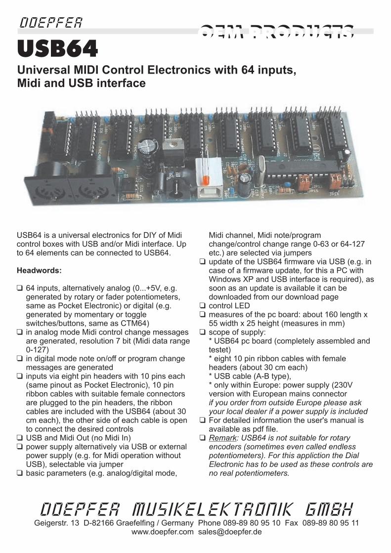
USB64 is a universal electronics for DIY of Midicontrol boxes with USB and/or Midi interface. Upto 64 elements can be connected to USB64.
64 inputs, alternatively analog (0...+5V, e.g.generated by rotary or fader potentiometers,same as Pocket Electronic) or digital (e.g.generated by momentary or toggleswitches/buttons, same as CTM64)in analog mode Midi control change messagesare generated, resolution 7 bit (Midi data range0-127)in digital mode note on/off or program changemessages are generatedinputs via eight pin headers with 10 pins each(same pinout as Pocket Electronic), 10 pinribbon cables with suitable female connectorsare plugged to the pin headers, the ribboncables are included with the USB64 (about 30cm each), the other side of each cable is opento connect the desired controlsUSB and Midi Out (no Midi In)power supply alternatively via USB or externalpower supply (e.g. for Midi operation withoutUSB), selectable via jumperbasic parameters (e.g. analog/digital mode,
Midi channel, Midi note/programchange/control change range 0-63 or 64-127etc.) are selected via jumpersupdate of the USB64 firmware via USB (e.g. incase of a firmware update, for this a PC withWindows XP and USB interface is required), assoon as an update is available it can bedownloaded from our download pagecontrol LEDmeasures of the pc board: about 160 length x55 width x 25 height (measures in mm)scope of supply:* USB64 pc board (completely assembled andtestet)* eight 10 pin ribbon cables with femaleheaders (about 30 cm each)* USB cable (A-B type),* only within Europe: power supply (230Vversion with European mains connector
For detailed information the user's manual isavailable as pdf file.
Headwords:
�
�
�
�
�
�
�
�
�
�
�
�
�
if you order from outside Europe please askyour local dealer if a power supply is included
: USB64 is not suitable for rotaryencoders (sometimes even called endlesspotentiometers). For this appliction the DialElectronic has to be used as these controls areno real potentiometers.
Remark
USB64Universal MIDI Control Electronics with 64 inputs,Midi and USB interface
OEM PRODUCTSDOEPFER
OEM PRODUCTS
DOEPFER MUSIKELEKTRONIK GMBHGeigerstr. 13 D-82166 Graefelfing / Germany Phone 089-89 80 95 10 Fax 089-89 80 95 11
www.doepfer.com [email protected]

OEM PRODUCTSDOEPFER
OEM PRODUCTS
DOEPFER MUSIKELEKTRONIK GMBHGeigerstr. 13 D-82166 Graefelfing / Germany Phone 089-89 80 95 10 Fax 089-89 80 95 11
www.doepfer.com [email protected]
CTM64
pc board dimensions:90 x 105 mm
CTM64 is an . Up tocan be connected to generate MIDI note on/off or
program change messages. CTM is suitable toor any
other contacts so that they are able to transmit MIDI data.Up to 4 can be connected to generate
and . Additionally a1/4 jack socket is available for connecting a .
are selected with the first of 8jumpers: or . In the note modeclosing of a contact generates the corresponding MIDI noteon message, opening generates note off - both withoutvelocity (velocity is fixed to 100). In the program changemode closing of a contact leads to the corresponding MIDIprogram change message.The (i.e. the MIDI note number assigned to thefirst contact) can be set to 0 or 36 with the second jumper.With two more jumpers one can transpose up/down oneoctave, i.e. +12/-12 semitones. Instead of these jumpers a3-position switch (1-0-1) working as an canbe soldered to the corresponding pins of the jumper pinheader. In this way the note offsets 0, 12, 24, 36 and 48 areavailable. If another note offset (e.g. 41) is required thecontacts are displaced correspondingly and the unusedcontact terminals are left free.In the program change mode the offset can be set to 1 or64, i.e. setting the program number range to 1-64 or 65-128(0-63 or 64-127 in MIDI code). With two daisy-chainedCTM64 the whole range 1...128 is covered.The plugs are used to connect up to 4potentiometers (e.g. rotary, slider, wheels) generating theMIDI messages
The 1/4“ jack socket can be used to insert a sustain pedal(contact type ”closed at rest” is required) generating theMIDI message (controller #64).The for all messages transmitted by theCTM64 is set with the last 4 jumpers.The 64 contacts are connected to four double row pinheaders with 16 pins each. 16 pin socket-connectors withflat cable can be connected to these pin headers (not
included with the CTM64). Additionally there is onecommon pin for all contacts. Pay attention that
can be used. This means that the contacts are notallowed to be connected with another electronics orconnected with a fixed voltage (e.g. GND).For the potentiometer four male pcb connectors with 3 pins(GND, slider, +5V) are available. Suitable femaleconnectors with assembled cables can be connected tothese pin headers (not included with the CTM64).CTM64 is equipped with and . Theincoming MIDI messages are to the datagenerated by the CTM64. In this way
together (e.g. 3 CTM64 required for 2 keyboardswith 61 keys and one basepedal with 32 keys, or switchboards with more than 64 switches).CTM64 is available only as an
. The pc board measures are about 90 x 105 mm.Four mounting holes with 3 mm diameter are available formounting the pc board to a suitable base e.g. with distancesleeves or spacers and screws (black dots in the abovepicture). The configuration of CTM64 (i.e. MIDI channel,mode, note offset and so on) is made by the customer with8 jumpers - as described above.We do not offer a suitable housing as the CTM64 isnormally installed into the housing of the keyboard orswitch board.An external power supply (7-12VDC@min. 250mA) isrequired. It is not included with the CTM64. You will find asuitable power supply in our price list. A connector setsuitable for CTM64 is available at extra charges. This setincludes four 16 pin flat cables with 16 pin socketconnectors pressed to the cables at one end (length about50cm) and four 3 pin female connectors with assembledcables for the potentiometers (length about 30cm,potentiometers are not included).
The is the (= IDI oontact) that converts 64 succeeding note or program
change messages into 64 0/+5V TTL signals. With suitabledrivers relays, lamps or electromagnetic valves can becontrolled via MIDI.
universal MIDI Out kit 64 freecontacts
retrofitkeyboards, switch panels, button arrangements
potentiometerscommon MIDI controllers pitch bend
sustain pedalTwo different modes
note on/off program change
note offset
octave switch
4 potentiometer
pitch-bend, modulation (controller #1),volume (controller #7) and monophonic after touch.
sustainMIDI channel
MIDI In MIDI Outmerged
several CTM64 canbe linked
assembled and tested pcboard
counterpart to CTM64
only freecontacts
M tC
MTC64
C T Montact- o- IDI
Universal
MIDI Out Kit

CTM RELAY BOARD
The is an expansion board for theuniversal . Thereason for this this additional board is the limited cablelength between CTM64 main board and the contacts(max. about 50 cm / 2 ft). By means of the relay boardthe cable length can be extended to 100 m (~ 300 ft) andeven more. The working principle is very simple: Therelay board is equipped with 16 reed relays that can beswitched via very long cables. The relay board is placednear the CTM64 main board and the contacts inside therelays are the new contacts for the CTM64 main board.Thus the cable length between the contacts and theCTM64 main board is less than 50cm but the cablesused to switch the relay can be very much longer. Foreach relay a screw terminal is available to connect asimple 2 pin cable with the controlling contact on theother side (e.g. a momentary or toggle switch). The relayboard is operated with a separate power supply to obtaina complete galvanic separation between the relays andthe CTM64 main board.These are the most important features:
16 Reed relays, the contacts of the relays are used asthe contacts for the CTM64 main board
relay connections via 2 pin screw terminalsup to four CTM relay boards can be connected to oneCTM64 main boardseparate power supply for the relay board(s),independent from the power supply of the CTM64main board. An external power supply with 7-12V DCoutput is required. The required current depends uponthe number of relays that have to be switched actually.Each relay consumes about 10mA. The full installation(i.e. 4 relay boards, all relays in operation) requires apower supply with about 640 mAadditional screw terminal to operate several relayboards with one power supply onlyconnection between each CTM relay board and theCTM64 main board via 16 pin ribbon cable, and onesingle cable (common line) that leads from the CTM64main board to all relay boardsthe 16 pin ribbon cable is included with the relayboardthe power supply has to be ordered in addition (onlyone required, even if more than one relay board isused), see accessories and price list
CTM Relay BoardMIDI control electronics CTMC64
�
�
�
�
�
�
�
�
� dimensions: 164 x 42 x 18 mm
OEM PRODUCTSDOEPFER
OEM PRODUCTS
MTV16Midi-to-Voltage Interface with 16Analog Voltage Outputs
�
�
interface to convert midi control changes messages to analog voltages16 analog voltage outputs 0 ... +5V, max. load ~ 10kOhmresolution of the voltages: 128 steps or 7 bit (based on the 7 bit midi data)the voltages are available as two pin heades with 10 pins each, each pinheader has available 8 voltages and GND on two pinsthe voltages are controlled by 16 subsequent midi control changes messageson the same midi channelthe midi channel is adjusted by means of four jumpersthe control change number of the first output can be set to 0, 16, 32, 48, 64,80, 96 or 112 by means of three jumpersconnectors for power supply and midi are available as sockets on the pcb
�
�
�
�
�
�
�
�
Midi activity LED displayready built and tested pc board, dimensions: about 78 x 67 x 25 mm
relays
LED controls
power supply
input
connectors to CTM64 main board
(common line)
relay control inputs (connected to simple on/off contacts)
power supply
output (to other
relay boards)
DOEPFER MUSIKELEKTRONIK GMBHGeigerstr. 13 D-82166 Graefelfing / Germany Phone 089-89 80 95 10 Fax 089-89 80 95 11
www.doepfer.com [email protected]

OEM PRODUCTSDOEPFER
OEM PRODUCTS
DOEPFER MUSIKELEKTRONIK GMBHGeigerstr. 13 D-82166 Graefelfing / Germany Phone 089-89 80 95 10 Fax 089-89 80 95 11
www.doepfer.com [email protected]
MTC64 is an that
.The TTL outputs of the MTC64 can be used to controldifferent switching functions. With suitable drivers (e.g.switching transistors)
and so on can becontrolled. A suitable 16-fold output driver board withmax. 40V/500mA is available for the MTC64. Forsmall loads (less than 5mA @ 5V, e.g. or high-impedance ) the additional drivers may notbe necessary.MTC64 has :
mode. In the note mode incoming MIDI noteon/off messages control the 64 TTL outputs providedthat the and correspond tothe settings of the MTC64. A note on message will setthe corresponding TTL output to a high level (+5V),the note off message will reset the output to a lowlevel (0V). With an additional jumper this bevaviourcan be set to the other way round (note on = low, noteoff = high) if reversed outputs are required.In the program change only one of the 64 outputs isactivated. The number of the activated output isidentical to the program change number received atthe MIDI input.The (i.e. the MIDI note number assignedto the first output) can be set to 0 or 36 with anotherjumper. With two more jumpers one can transposeup/down one octave, i.e. +12/-12 semitones. Thus thenote offsets 0, 12, 24, 36 and 48 are obtainable. Ifanother note offset is required the unused outputsremain unconnected.In the mode the can be set to1 or 64, i.e. setting the program number range to 1-64or 65-128 (0-63 or 64-127 in MIDI code). With twodaisy-chained MTC64 the whole program numberrange 1-128 is covered. Alternatively a range switchcan be used instead of the range jumper.
The for all messages processed by theMTC64 is set with the last 4 jumpers.The are available as four double rowpin headers with 16 pins each. 16 pin socket-connectors with flat cable can be connected to thesepin headers (not included with the MTC64).Additionally there are some GND pins available (assolder pins and as additional pin header with 10 pins)as a GND reference level is required for the devicescontrolled by the MTC64 outputs.MTC64 is equipped with and . Theincoming MIDI messages are passed to MIDI Thru. Inthis wayMTC64 is available as an
only. We do not offer a suitable housing as theMTC64 is normally installed into the housing of thedevice to be controlled by MTC64.An (7-12VDC@min. 250mA)is required. It is not included with the MTC64. You willfind a suitable power supply in our price list.A suitable for MTC64 is available atextra charges.This includes four 16 pin flat cableswith 16 pin socket connectors at one end and one 10pin flat cable with 10 pin socket connector at one end.The length for all cables is about 50cm.
The MTC64 is the ( ontact-o- IDI Interface) that generates up to 64 MIDI noteon/off or program change messages with freecontacts connected to CTM64 (for details please referto the ).
universal MIDI interface convertsup to 64 succeeding MIDI note on/off or programchange messages into 64 TTL voltages (0/+5V)
relays, lamps, motors,electromagnets, magnetic valves
LEDsreed relays
two different modes note or programchange
MIDI channel note range
note offset
program change offset
MIDI channel
64 TTL outputs
MIDI In Thru
several MTC64 can be linked together.assembled and tested pc
board
external power supply
connector set
counterpart to CTM64
CTM64 product information
A suitable 16-fold output driver board with max.40V/500mA is available at extra charges. Each outputboard is connected to the main board simply with aflat cable (included with the driver board). The driveroutputs are available as 16 single pin holders. Thepower supply for the loads driven by the driver boardis not included and has to be added by the customer(depends upon the voltage and current of the loads).
Ct M
MTC64
pc board dimensions:70 x 102 mm
M T CIDI- o- ontact/
Gate-Interface
Universal kit for
MIDI controlled
switching applications

The MTC Power Board is an expansion board for theuniversal . It is used toswitch mains voltages (230V/115V) to drive mainsvoltage devices. For example lamps or other mains loadscan be controlled by MIDI note on/off messages.These are the most important features:
16 power outputs 115V or 230Vmax. 2A for each output (i.e. 460 Watt/VA @ 230Vresp. 230Watt/VA @ 115V)max. total load for all outputs 16 A, i.e. 1A for eachoutput in case of equal loads for all outputs (= 115Watt/VA @ 115V resp. 230Watt/VA @ 230V)zero crossing switches to reduce mains interferencesseparate fuse for each outputmains and load connections via screw terminalsup to four MTC power boards can be connected to oneMTC64 main boardconnection between MTC power boards and MTC64main board via one 10 pin ribbon cable leading fromthe main board to all power boards, and a 16 pin
ribbon cable between main board and power board(one for each power board). Please specify how manypower boards have to be connected to the main board(because of the lenght and number of femaleconnectors of the 10 pin ribbon cable)ribbon cables are included with the power board,cables for mains and loads connection are notincluded
MIDI control electronics MTC64
�
�
�
�
�
�
�
�
�
� Installation and wiring of the MTC power boardhas to be carried out by qualified personnel onlybecause of electrical safety (dangerous mainsvoltage 115V / 230V). Not qualified personell is notallowed to install and run the MTC power board !DANGER TO LIFE ! The user has to read theinstallation manual carefully and follow allinstructions in the manual meticulously ! Thecomplete construction has to be mounted into anisolating case before the mains voltage is applied.For more detailed information the user's guide isavailable for download on our web site
OEM PRODUCTSDOEPFER
OEM PRODUCTS
MTC POWER BOARDconnectors to
MTC64 main board
mains input
power outputs
solid state
relays
fuses
The MTC Relay Board is an expansion board for theuniversal . It has 16relays available that can be used as switches for manyapplications (e.g. audio signals, control signals, lowvoltage lamps/motors/magnets and many more). Anotherapplication is to connect the relay outputs in parallel tothe key contacts of a synthesizer, organ or any electronicinstrument that cannot be interfaced to Midi with anothermethod.These are the most important features:
relay connections via screw terminalsLED control for each outputup to four MTC relay boards can be connected to oneMTC64 main boardconnection between MTC relay boards and MTC64main board via one 10 pin ribbon cable leading fromthe main board to all relay boards, and a 16 pinribbon cable between main board and relay board(one for each relay board). Please specify how manyrelay boards have to be connected to the main board(because of the lenght and number of femaleconnectors of the 10 pin ribbon cable)ribbon cables are included with the relay board,cables for relay connections are not included
MIDI control electronics MTC64
�
�
�
�
�
�
�
�
�
�
�
�
16 potential-free relay contacts (Reed relays)maximum current for each relay contact: 1Amaximum voltage for each relay contact: 50Vmaximum power for each relay contact: 15W (15VA)(it is not allowed to go beyond any of these values,e.g. for 1A current the maximum voltage is 15V,otherwise the maximum power of 15VA would beexceeded)
residual resistance of closed contact: 150mOhm
For more detailed information the user's guide isavailable for download on our web site
dimensions: 163 x 52 x 18 mm
MTC RELAY BOARD
connectors to
MTC64 main board
relay outputs
relays
LED controls
OEM PRODUCTSDOEPFER
OEM PRODUCTS
DOEPFER MUSIKELEKTRONIK GMBHGeigerstr. 13 D-82166 Graefelfing / Germany Phone 089-89 80 95 10 Fax 089-89 80 95 11
www.doepfer.com [email protected]
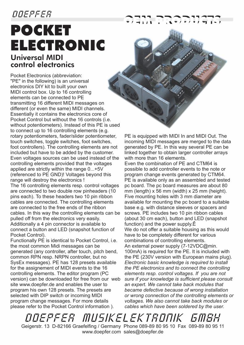
Pocket Electronics (abbreviation:"PE" in the following) is an universalelectronics DIY kit to built your ownMIDI control box. Up to 16 controllingelements can be connected to PEtransmitting 16 different MIDI messages ondifferent (or even the same) MIDI channels.Essentially it contains the electronics core ofPocket Control but without the 16 controls (i.e.without potentiometers). Instead of this PE is usedto connect up to 16 controlling elements (e.g.rotary potentiometers, fader/slider potentiometer,touch switches, toggle switches, foot switches,foot controllers). The controlling elements are notincluded but have to be added by the customer.Even voltages sources can be used instead of thecontrolling elements provided that the voltagesapplied are strictly within the range 0...+5V(referenced to PE GND)! Voltages beyond thisrange will destroy the electronics !The 16 controlling elements resp. control voltagesare connected to two double row pinheaders (10pins each). To these headers two 10 pin ribboncables are connected. The controlling elementsare connected to the free ends of the ribboncables. In this way the controlling elements can bepulled off from the electronics very easily.Additionally a 4 pin connector is available toconnect a button and LED (snapshot function ofPocket Control).Functionally PE is identical to Pocket Control, i.e.the most common Midi messages can begenerated (any controller, after touch, pitch bend,common RPN resp. NRPN controller, but noSysEx messages). PE has 128 presets availablefor the assignement of MIDI events to the 16controlling elements. The editor program (PCversion) can be downloaded for free from our website www.doepfer.de and enables the user toprogram his own 128 presets. The presets areselected with DIP switch or incoming MIDIprogram change messages. For more detailsplease refer to the Pocket Control information ).
PE is equipped with MIDI In and MIDI Out. Theincoming MIDI messages are merged to the datagenerated by PE. In this way several PE can belinked together to obtain larger controller arrayswith more than 16 elements.Even the combination of PE and CTM64 ispossible to add controller events to the note orprogram change events generated by CTM64.PE is available only as an assembled and testedpc board. The pc board measures are about 80mm (length) x 56 mm (width) x 25 mm (height).Five mounting holes with 3 mm diameter areavailable for mounting the pc board to a suitablebase e.g. with distance sleeves or spacers andscrews. PE includes two 10 pin ribbon cables(about 30 cm each), button and LED (snapshotfunction) and the power supply.ÊWe do not offer a suitable housing as this wouldhave to be completely different for variouscombinations of controlling elements.An external power supply ([email protected]) is required for the PE. It is included withthe PE (230V version with European mains plug).Electronic basic knowledge is required to installthe PE electronics and to connect the controllingelements resp. control voltages. If you are notsure if your knowledge is sufficient please consultan expert. We cannot take back modules thatbecame defective because of wrong installationor wrong connection of the controlling elements orvoltages. We also cannot take back modules orcables which have been soldered by the user.
ELECTRONICUniversal MIDIcontrol electronics
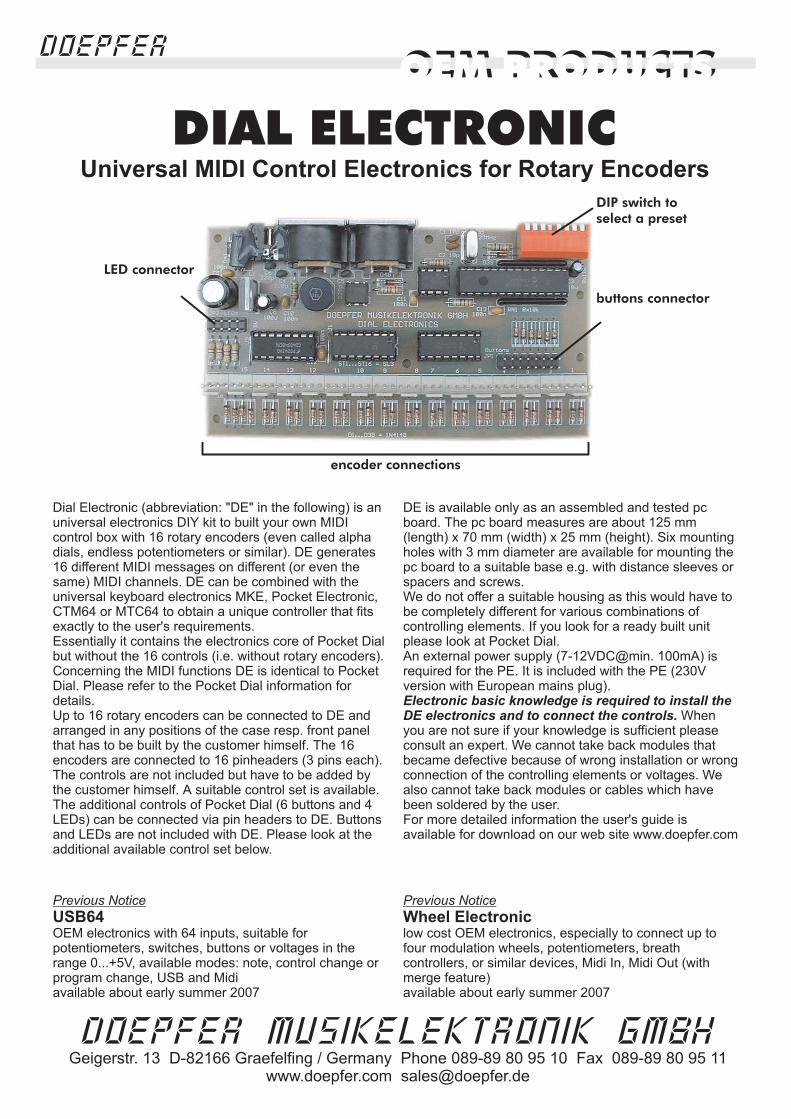
Dial Electronic (abbreviation: "DE" in the following) is anuniversal electronics DIY kit to built your own MIDIcontrol box with 16 rotary encoders (even called alphadials, endless potentiometers or similar). DE generates16 different MIDI messages on different (or even thesame) MIDI channels. DE can be combined with theuniversal keyboard electronics MKE, Pocket Electronic,CTM64 or MTC64 to obtain a unique controller that fitsexactly to the user's requirements.Essentially it contains the electronics core of Pocket Dialbut without the 16 controls (i.e. without rotary encoders).Concerning the MIDI functions DE is identical to PocketDial. Please refer to the Pocket Dial information fordetails.Up to 16 rotary encoders can be connected to DE andarranged in any positions of the case resp. front panelthat has to be built by the customer himself.
The controls are not included but have to be added bythe customer himself. A suitable control set is available.The additional controls of Pocket Dial (6 buttons and 4LEDs) can be connected via pin headers to DE. Buttonsand LEDs are not included with DE. Please look at theadditional available control set below.
DE is available only as an assembled and tested pcboard. The pc board measures are about 125 mm(length) x 70 mm (width) x 25 mm (height). Six mountingholes with 3 mm diameter are available for mounting thepc board to a suitable base e.g. with distance sleeves orspacers and screws.We do not offer a suitable housing as this would have tobe completely different for various combinations ofcontrolling elements. If you look for a ready built unitplease look at Pocket Dial.An external power supply (7-12VDC@min. 100mA) isrequired for the PE. It is included with the PE (230Vversion with European mains plug).
Whenyou are not sure if your knowledge is sufficient pleaseconsult an expert. We cannot take back modules thatbecame defective because of wrong installation or wrongconnection of the controlling elements or voltages. Wealso cannot take back modules or cables which havebeen soldered by the user.
The 16encoders are connected to 16 pinheaders (3 pins each).
For more detailed information the user's guide isavailable for download on our web site www.doepfer.com
Electronic basic knowledge is required to install theDE electronics and to connect the controls.
DIAL ELECTRONIC
LED connector
encoder connections
buttons connector
DIP switch to
select a preset
Universal MIDI Control Electronics for Rotary Encoders
OEM PRODUCTSDOEPFER
OEM PRODUCTS
DOEPFER MUSIKELEKTRONIK GMBHGeigerstr. 13 D-82166 Graefelfing / Germany Phone 089-89 80 95 10 Fax 089-89 80 95 11
www.doepfer.com [email protected]
Previous Notice
USB64 Wheel ElectronicOEM electronics with 64 inputs, suitable forpotentiometers, switches, buttons or voltages in therange 0...+5V, available modes: note, control change orprogram change, USB and Midiavailable about early summer 2007
low cost OEM electronics, especially to connect up tofour modulation wheels, potentiometers, breathcontrollers, or similar devices, Midi In, Midi Out (withmerge feature)
Previous Notice
available about early summer 2007

Wheel Electronic (abbreviation: "WE" in the following) is auniversal electronics DIY Midi kit designed to connectmodulation or pitch wheels. But it can be used also for joysticks, single or multiple foot controllers (analog or on/off),breath controllers or even normal potentiometers. In additiona connector for a sustain foot switch is available. Up to 4continuously variable "analog" elements and a "digital"switching element (e.g. a sustain foot switch) can beconnected.Application examples:
wheelspitch benderjoy sticksbreath controllersfoot controllers (continuos)foot switches (on/off), momentary or togglerotary potentiometersslider/fader potentiometers
Different elements can be combined simultaneously. Hereare some examples:
pitch bender, modulation wheel, volume control (rotary orslider potentiometer), breath controller and sustain footswitchpitch bender, three modulation wheels (e.g. modulation,volume, after touch) and sustain foot switchpitch bender, two modulation wheels (e.g. modulationand after touch), one rotary or slider potentiometer(volume) and sustain foot switchpitch bender, modulation wheel and joy sticktwo joy sticksfour foot controllers for volume control of four Midichannelsdual or tripe foot controller (on/off or analog) and rotary orslider potentiometertwo modulation wheels or switches to control the rotaryspeakers of the organ software B4 (von NativeInstruments), two rotary or slider potentiometers forvolume and expression
The four "analog" elements are connected to pinheaderswith 3 pins. For the "digital" switching element a pinheaderwith 2 pins is available. Four 3-pin cable sets and one 2-pincable set about 30cm each with suitable female connectorsare included.WE has some special features:The upper voltage that is assigned to the Midi data value127 can be adjusted exactly with a multi-gang trimmingpotentiometer in the range +3...+5V. This measure isnecessary e.g. for modulation or pitch wheels, footcontrollers or joy sticks that do not cover the complete angle
of rotation. Even breath controllers (e.g. Yamaha BC-1/2/3)output only about +3.5V maximal control voltage.For each of the four elements a jumper is used to select ifthe full voltage range (0...+5V) or the adjustable voltagerange is used for measurement. This is necessary ifdifferent elements are used simultaneously (e.g. modulationwheel and slider potentiometers).If an element is assigned to Midi pitch bend a "plateau" isused in the middle of the voltage/data range (data value64). This feature is meaningful in combination with spring-loaded wheels or joy sticks as due to mechanical tolerancesthe exact center position is not always reached.Four jumpers are used to select the Midi channel.Further four jumpers are used to select up to 16 differentcombinations of Midi control change numbers, pitch bend orafter touch - the so-called presets. A detailed list of allavailable combinations can be found in the user's manualThe elements connected to WE (e.g. wheels, joy sticks, footcontrollers, normal potentiometers, foot switch) are notincluded but have to be added or purchased in addition bythe customer. The Midi data range is 0...127 with 7 bitresolution.The sampling rate is about 50 samples/second.WE is equipped with MIDI In and MIDI Out. The incomingMIDI messages are merged to the data generated by WE-provided that the incoming Midi data range is not too big. Inthis way several WE can be linked together or combinedwith other electronics like CTM64, MKE, Pocket Electronicor Dial Electronic).An LED is used to indicate the Midi activity.WE is available only as an assembled and tested pc board.The pc board measures are about 60 mm (length) x 55 mm(width) x 25 mm (height). Several mounting holes with 3mm diameter are available for mounting the pc board to asuitable base e.g. with distance sleeves or spacers andscrews.We do not offer a suitable housing as this would have to becompletely different for various combinations of controllingelements.An external power supply (7-12VDC@min. 100mA) is used.Within Europe the wall outlet power supply adapter for 230Vmains voltage and European type mains plug is includedwith the WE. In other countries the power supply has to bepurchased by the user in his country. If there is a Doepferrepresentative in your country please ask the representativeif the power supply is included in your country.
�
�
�
�
�
�
�
�
�
�
�
�
�
�
�
�
WHEEL
ELECTRONICUniversal Midi electronicsfor wheels, foot controllersjoy-sticks, breath-controllers
OEM PRODUCTSDOEPFER
OEM PRODUCTS
DOEPFER MUSIKELEKTRONIK GMBHGeigerstr. 13 D-82166 Graefelfing / Germany Phone 089-89 80 95 10 Fax 089-89 80 95 11
www.doepfer.com [email protected]

MKE
external power supply
is an Universal Midi Keyboard Electronics to builtcustom-made Midi controllers that include a keyboard.Combining the MKE with our controller electronics PocketElectronic, Dial Electronic, Wheel Electronic, CTM64 orMTC64 allows the construction of an unique Midi controllerthat exactly meets the requirements of the user. Theseunits can be connected to MKE:
Any keyboard manufactured by FATAR/Italy with 2, 3, 4or 5 octaves (with velocity)By means of a special adapter board even the dynamicbasspedals PD/2A manufactured by FATAR/Italy can beconnected (avialable with 13, 17 or 20 keys)Pitch bend wheel (special spring-loaded rotarypotentiometer)Modulation wheel (special rotary potentiometer)Rotary or fader potentiometer for loudness/volumecontrol (Midi CC#7)After touch sensor or socket for sustain switch oranother potentiometer for any Midi controller
The MKE pc board has these controls available:6 rectangle momentary buttons with integrated LEDs3-digit LED display
The 6 buttons are used to control these parameters:Midi channel 1...16Transpose (lowest note = 0,12,24,36,48,60)Program change 0...127Controller number 0...127 resp. After touchUp/down (increment/decrement of the current value)
MKE is equipped with Midi In and Midi Out. The dataappearing at the Midi in are merged to the data generatedby the MKE. Several MKE can be daisy-chained orcombined with other OEM controllers (e.g. PocketElectronic, Dial Electronic, Wheel Electronic, CTM64) tobuilt a custom-made Midi controller.
MKE is available as an assembled and tested pc board.The pc board measures are about 68 mm (length) x 85(width) x 35 mm (height).Please specify in your order the type of keyboard (2/3 or4/5 octaves). This is necessary as the keyboards with 2and 3 octaves have different connectors compared to the 4and 5 octaves versions. Suitable cables to connect MKEand the keyboard are required. If you have no keyboardavailable we recommend to order the keyboard togetherwith the MKE as in this case the components are alreadyconnected and tested together. The MKE is available as apackage together with different types of keyboards (e.g.with the organ waterfall keyboard TP/8O).We do not offer a suitable housing as this would have to becompletely different for various combinations of keyboardsand controlling elements.An (7-12VDC@min. 250mA) isrequired for the PE. In Europe it is included with the MKE(230V version with European mains plug). For othercountries please contact the representative in your country.We have several accessories available: suitable keyboards(2, 3, 4 or 5 octaves), cables for the connection betweenMKE and the keyboards, wheels, cable sets for the wheelsand the volume potentiometer, wheels and sustain socket.For details please take a look at our price list (spare partssection) or ask our sales office ([email protected]).If you order the MKE without keyboard please specify thekeyboard that will be used (2, 3, 4 or 5 octaves). Theconnectors are different for the keyboards and theelectronics has to be equipped with the suitableconnectors. The cables leading to the keyboards are notincluded and have to be ordered in addition.
�
�
�
�
�
�
�
�
�
�
�
�
�
MKE has a non-volatile memory for the parameters Midichannel, transpose, program and controller number. Afterthe next power on the previous values are called up. For more
detailed information the user's guide and a guide how toconnect other keyboards are available for download on ourweb site www.doepfer.com.
MKE Universal Midi Keyboard Electronics
OEM PRODUCTSDOEPFER
OEM PRODUCTS
DOEPFER MUSIKELEKTRONIK GMBHGeigerstr. 13 D-82166 Graefelfing / Germany Phone 089-89 80 95 10 Fax 089-89 80 95 11
www.doepfer.com [email protected]

MBP25 is an electronics that was developed toconnect the non-dynamic basspedals PD/3manufactured by Fatar/Italy (for the dynamic basspedals PD/2A the MKE electronics can be used incombination with a suitable adapter board).Unfortunately Fatar does not offer bass pedals with 25or more keys but only versions with 13, 17 or 20 keys.As many customers have been asking for a basspedalwith 25 keys we decided to develop the MBP25 thatcan be used to connect one, two or three basspedalswith 13 keys each (Fatar PD/3) to obtain a 13, 25 or 37key basspedal. The above picture shows onepossibility how two PD/3 pedals can be combined toobtain a 25 key pedal with case.We offer a DIY/OEM package for a 25 key basspedal.It is made of two 13 keys pedals PD/3 and the MBP25electronics. One of the two pedals has to beshortended by one key as one of the "C" keys isredundant. Fortunately the PD/3 pedals use a plasticframe and can be shortened with passable effort. Bothpedals have to be mounted on a common base plateand a suitable case (e.g. made of varnished wood - asshown above) can be added. The base plate and thecase are and have to be added by thecustomer.
These are the most important features of the MBP25electronic kit:
6 black rectangle momentary buttons (about 12 x 22mm) with integrated LEDs (same as used into adjust these parameters
measures of the complete button area about 76 x22 mm3-digit LED display (about 19 x 38 mm) forparameter displaytwo connectors for basspedals (compatible to FatarPD/3)Midi In, Midi Out (connected via 30 cm long cablesto enable the mounting of the sockets at thedesired position)The data appearing at the Midi in are merged to thedata generated by the MBP25. Consequently theMBP25 can be connected to a Midi keyboard toadd the basspedal data to the keyboard data.power supply socket on board, in addition a 2-pinconnector is available to connect another powersupply socket near the Midi sockets (2-pin cable 30cm with suitable female connector is included)a 3-pin connector is available to connect a rotary orfader potentiometer that transmits Midi volume,even a foot controller (e.g. FP5) can be connected.the (fixed) velocity value can be set to any valuebetween 1 and 127.
not included
Remark: All basspedals manufactured by Fatar thatinclude velocity (PD/2A) are equipped with solid steelframes and cannot be shortened in such an easy wayand cannot be connected to MBP25.
�
�
�
�
�
�
�
�
�
�
�
�
�
�
�
�
�
�
A third pedal can be added in the same way.For this application a special connection cable withthree connectors on one of the ribbon cables isrequired.
Midi channel 1...16Transpose probably in octave intervalsProgram Changeoperating mode:note: this is the usual play mode, the keystransmit Midi note on/off messageprogram change: in this mode the keys are usedto transmit Midi program change messagesrealtime: in this mode three of the keys are usedto transmit Midi start, stop and continueUp (increment of the value shown in the display)Down (decrement of the value shown in thedisplay)
)MKEAn external power supply (7-12VDC@min. 100mA) isrequired for the PE. It is included with the PE (230Vversion with European mains plug).
MBP25Midi Basspedal Electronics
application example pc board
OEM PRODUCTSDOEPFER
OEM PRODUCTS
DOEPFER MUSIKELEKTRONIK GMBHGeigerstr. 13 D-82166 Graefelfing / Germany Phone 089-89 80 95 10 Fax 089-89 80 95 11
www.doepfer.com [email protected]