國 立 交 通 大 學 電信工程學系 博 士 論 文 · with the similar aperture-couple...
TRANSCRIPT

國 立 交 通 大 學
電信工程學系
博 士 論 文
圓柱形洩漏波天線與寬頻
平面式洩漏波天線
Leaky-Wave Antennas on Cylinder Substrates
and Broadband Planar Leaky-Wave Antennas
研 究 生:林烈全 (Lieh-Chuan Lin)
指導教授:林育德 博士 (Dr. Yu-De Lin)
指導教授:黃瑞彬 博士 (Dr. Ruey Bing Hwang)
中 華 民 國 九 十 七 年 九 月

圓柱形洩漏波天線與寬頻平面式洩漏波天線
Leaky-Wave Antennas on Cylinder Substrates and
Broadband Planar Leaky-Wave Antennas
研 究 生:林烈全 Student: Lieh-Chuan Lin
指導教授:林育德 博士 Advisor: Dr. Yu-De Lin
黃瑞彬 博士 Dr. Ruey-Bing Hwang
國立交通大學
電信工程學系
博士論文
A Dissertation
Submitted to Institute of Communication Engineering
College of Electrical and Computer Engineering
National Chiao Tung University
in Partial Fulfillment of the Requirements
for the Degree of Doctor of Philosophy
in
Communication Engineering
Hsinchu, Taiwan
2008 年 9 月

I
圓柱形洩漏波天線與寬頻平面式洩漏波天線
研究生: 林烈全 指導教授: 林育德 博士
黃瑞彬 博士
國 立 交 通 大 學
電 信 工 程 學 系
摘要
本論文研究兩種形式的洩漏波天線:圓柱形介質上的洩漏波天線與平面介質
上的洩漏波天線。在理論上採用全波分析法-頻域法(Spectral domain approach)
來研究這兩種構造中洩漏波的傳播特性。
首先文中第一部分提出圓柱形微帶洩漏波天線。從數值計算得到的傳播常數
可得知圓柱形微帶洩漏波天線與平面式微帶洩漏波天線有著相同的特性。利用孔
徑耦合饋入結構,我們成功的激發了圓柱形微帶線的第一高階洩漏模,並實作出
高增益與寬頻的洩漏波天線。
同時本文也探討另外兩種圓柱形結構:挖槽同軸電纜與圓柱形共平面波導。
由理論計算得到不同電路尺寸參數下對此類圓柱形洩漏波天線傳播特性的影響,
進一步決定操作頻率。接著也設計了兩種對應結構的天線並加以量測。
本文第二部份則是主要著重在平面式洩漏波天線的設計上。我們研究槽線第
一高階洩漏模與接地介質板的表面波之間的關係。在電路製作上用微帶線至共平

II
面波導的轉換電路,來激發槽線的第一高階洩漏模,設計出一支非常寬頻的天線。
最後本文提出一種新穎的倒T形洩漏波天線。它與單導體洩漏波天線有著相
同的特性,例如超寬頻與固定的主波束角度。和單導體洩漏波天線相比,倒T形
天線不需要寬頻的反相器,而且天線寬度也只有原來的一半,所以倒T形天線在
實作上具有更大的方便性。

III
Leaky-Wave Antennas on Cylinder Substrates and
Broadband Planar Leaky-Wave Antennas
Student: Lieh-Chuan Lin Advisor: Dr. Yu-De Lin
Dr. Ruey-Bing Hwang
Department of Communication Engineering
National Chiao Tung University
Abstract
This thesis proposes two types of leaky-wave antennas. One type is on a
cylindrical substrates and the other type is on a planar substrate. The well-known
full-wave method, spectral domain approach, is applied to investigate the propagation
characteristics of leaky modes on both configurations.
First, a cylindrical microstrip leaky-wave antenna is analyzed and designed. From
the numerical results of computed propagation constants, it has the same characteristics
as those of the planar ones. With the similar aperture-couple feeding structures used in
planar microstrip leaky-wave antennas, the first higher order leaky mode is
successfully excited. In addition, a high gain and wideband leaky-wave antenna is
implemented.
Moreover, the first higher leaky modes on two cylindrical structures, slotted
coaxial lines and cylindrical coplanar waveguides, are also studied. The effects of
different parameters are shown and can be used to decide the operating frequency band

IV
of leaky-wave antennas. Two design examples are presented to show the performance
of these types of leaky-wave antennas.
Second, the relationship between the first higher order leaky mode of a slotline
and surface wave mode on a grounded dielectric slab is presented. A slotline
leaky-wave antenna fed by a wideband microstrip-to-CPW transition is demonstrated.
Finally, an inverted-T leaky-wave antenna is introduced. It has the same
properties as the single-conductor strip leaky-wave antennas, such as wide bandwidth
and fixed mainbeams. Compared to the single-conductor strip antennas, the broadband
phase inverter is not needed and the antenna width is halved. Therefore, the realization
of inverted-T antennas is easier than that of single-conductor strip ones.

V
ACKNOWLEDGEMENT
首先感謝林育德教授與黃瑞彬教授四年多來的指點,讓我能毫無窒礙一路順
利完成博士學業。感謝碩士班指導老師陳君鍵教授的教導,建立我博士班求學所
需的電磁理論基本功夫。想當年電磁學考過四分的我,如今也快完成電波博士學
位,這彷彿是冥冥之中就注定好的。此外亦感謝交大電信系高銘盛教授、陳伯寧
教授、吳霖堃教授在求學生涯中的建議與協助。
在交大轉眼間已過十個寒暑,交大各方面充足的設備使我研究資源不虞匱乏
提供了強力的後援。實驗室待了六個多年頭,想起過去與已經畢業的學長學弟們
一起奮鬥的日子我永遠記得,數十位台灣微波界的鬥士們族繁不及備載,在此一
併感謝各位戰友。
感謝大學死黨法蘭蘇、小支藍、機車嘉與其他交大電信 91 級同學們,帶給我
大學時代的美好時光。
感謝奚韞婷小姐三年多來的相互扶持與鼓勵,這難能可貴的緣份,陪伴我堅
強走完這求學旅程。
最後感謝父母與兩位姐姐二十幾年來的養育照顧,家中雖不富有但也足以供
我完成博士學業,當了快三十年的米蟲實感羞愧。長年在北部讀書甚少回家,爸
媽跟姐姐們是我最強大的支柱,謝謝你們!

VI
CONTENTS
ABSTRACT (Chinese)…………...…………………………………………..........i
ABSTRACT (English)………………………………………………………........iii
ACKNOWLEDGEMENT…………………………………………………….....v
CONTENTS…...…...…………………………………………………………….....vi
LIST OF FIGURES………………………………………………………...…...viii
CHAPTER 1 Introduction………………...………………………………..…....1
1.1 Motivations……………………………………………………………..…… .1
1.2 Organization of This Thesis…………………………………………………...2
CHAPTER 2 Cylindrical Microstrip Leaky-wave Antennas…………....4
2.1 Spectral Domain Analysis……………………………………...……………...4
2.2 Numerical Results………………………………………...…………….……..9
2.2.1 Convergence Test......................................................................................9
2.2.2 Comparison of the Results from the SDA to the Result from the
Leaky-Mode Scattering Parameter Extraction…….............................. 10
2.2.3 Effect of Different Outer Radii…….......................................................11
2.2.4 Effect of Different Substrate Thicknesses...............................................13
2.2.5 Effect of Different Line Widths……......................................................14
2.3 Design Example and Measurement……………………………………….....15
2.4 Summary………………………………………..............................................20
CHAPTER 3 Leaky Modes on Cylindrical Substrates.............................21
3.1 Leaky Modes of Slotted Coaxial Lines……………………...…………….....21
3.1.1 Spectral Domain Analysis of Slotted Coaxial Lines…………………...21
3.1.2 Numerical Results……………………………………………………...23
3.1.3 Design Example: A Conductor-backed Slotline Leaky-wave

VII
Antenna………………………………………………………………..26
3.2 Leaky Modes of Coplanar Waveguides on Cylindrical Substrates…………..30
3.2.1 Spectral Domain Analysis of Coplanar Waveguides on Cylindrical
Substrates……………………………………………………………...30
3.2.2 Numerical Results……………………………………………………...31
3.2.3 Design Example: A Cylindrical Coplanar Waveguide Leaky-wave
Antenna..................................................................................................34
CHAPTER 4 Broadband Leaky-wave Antennas........................................37
4.1 Slotline Leaky-Wave Antennas……………………………………………...37
4.2 Broadband Inverted-T Leaky-Wave Antenna ……………………………….43
CHAPTER 5 Conclusion and Future Works...............................................48
APPENDIX............................. ............................. ............................. .....................50
REFERENCES.............................................................................................. .........52

VIII
LIST OF FIGURES
Fig. 2.1 The cross-sectional view of the cylindrical microstrip line…………………....6
Fig. 2.2 The PEC boundary representation and transformation………………………...6
Fig. 2.3 Convergence of series z zz zzJ G J�� � . w = 10 mm, h = 0.508 mm, εr =2.2, and b =
10 and 20 mm at 9.5GHz………………..………………………………….....9
Fig. 2.4 Convergence of normalized phase constant and normalized attenuation constant
of cylindrical microstrip leaky-wave antenna. w = 10 mm, h=0.508mm, εr =2.2,
b =10 and 20 mm at 9.5GHz...............................……………………............ 10
Fig. 2.5 Comparisons of propagation constants of the first higher order mode (w = 10
mm, h = 0.508 mm, εr = 2.2, b = 30 mm )…………………………………..11
Fig. 2.6 Normalized phase constants of the first higher order mode ( w = 10 mm, h =
0.508 mm, εr = 2.2, b = 10, 20, 30 mm and planar ). ……………........12
Fig. 2.7 Normalized attenuation constants of the first higher order mode (w = 10 mm,
h = 0.508 mm, εr = 2.2, b = 10, 20, 30 mm and planar )…. …………..12
Fig. 2.8 Propagation constants of the first higher order mode ( w = 10 mm, h =0.508
and 1.570 mm, εr = 2.2, b = 10 mm )…………………………….…....13
Fig. 2.9 Propagation constants of the first higher order mode ( w = 9, 10, and 11 mm,
h = 0.508 mm, εr = 2.2, b = 30 mm )…………………………………..14
Fig. 2.10 The feeding and the antenna structure…………………………………........15
Fig. 2.11 The top view of feeding and the antenna structure……………………….....17
Fig. 2.12 Measured return loss of the cylindrical microstrip antenna with two angular
widths (w = 10 mm, h = 0.508 mm, εr = 2.2, b = 20 and 30 mm)………….17
Fig. 2.13 Measured copolarization radiation patterns of the cylindrical microstrip
antenna with an outer radius b = 20 mm…………………….......…….....18

IX
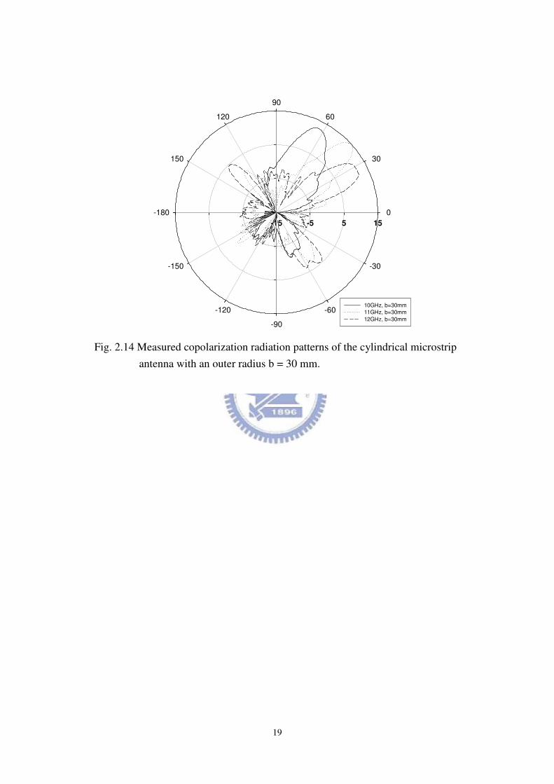
Fig. 2.14 Measured copolarization radiation patterns of the cylindrical microstrip
antenna with an outer radius b = 30 mm………………………………...…..19
Fig. 3.1 (a) The cross-sectional view of the slotted coaxial line. (b) The PMC boundary
representation the slotted coaxial line……………….......................……......22
Fig. 3.2 The normalized propagation constants of different slot widths ( b = 100 mm, h
= 10 mm, εr = 2.2, and w = 10, 15 and 20 mm)………………………......24
Fig. 3.3 The normalized propagation constants of different slot widths ( b = 100 mm, h
= 10 mm, εr = 2.2, and w = 10, 15 and 20 mm).……………………….....25
Fig. 3.4 The normalized propagation constants of different substrate thicknesses ( b =
50 mm, h = 6, 8, and 10 mm, εr = 2.2, and w = 10 mm)…………...............25
Fig. 3.5 The proposed conductor-backed slotline leaky-wave antenna…………….... 26
Fig. 3.6 The normalized phase constants and attenuation constants………………..... 27
Fig. 3.7 The return loss of the conductor-backed slotline antenna…………………....28
Fig. 3.8 The copolarization radiation patterns at 13, 14 15 GHz in the xz-plane…..…28
Fig. 3.9 The copolarization radiation patterns at 16, 17, 18 GHz in the xz-plane….... 29
Fig. 3.10 (a) The cross-sectional view of the CPW on the cylindrical substrate (b) The
PEC boundary representation……………………………………………….30
Fig. 3.11 The normalized propagation constants of different outer radii ( b = 10, 12 and
14 mm, h =0.508 mm, εr = 2.2, s = 5 mm, and w = 10 mm). …….........….32
Fig. 3.12 The normalized propagation constants of different center strip widths ( b =
20 mm, h =0.508 mm, εr = 2.2, s = 5 mm, and w = 10, 8, and 6 mm)....33
Fig. 3.13 The normalized propagation constants of different slot widths ( b = 20 mm,
h =0.508 mm, εr = 2.2, s = 10, 5, and 1 mm, and w = 10 mm)…..…….33
Fig. 3.14 The proposed cylindrical coplanar waveguide leaky-wave antenna………. 34
Fig. 3.15 The normalized phase constants and attenuation constants………………....35

X
Fig. 3.16 The measured return loss of the proposed cylindrical coplanar waveguide
leaky-wave antenna………………………………………………………....35
Fig. 3.17 The measured copolarization radiation patterns at 6, 7, and 8 GHz in the
xz-plane…………….....……………………………………………….......36
Fig. 3.18 The measured copolarization radiation patterns at 9, 10, and 11 GHz in the
xz-plane. ……………………………………………………………………..36
Fig. 4.1 (a) The single-conductor strip line with the virtual PEC. (b) The slotline with
the virtual PMC. ……...…. ………………………………………………….37
Fig. 4.2 The normalized phase constants and attenuation constants of slotlines and TM1
surface wave mode of grounded dielectric slab (w=0 case)…………............38
Fig. 4.3 The proposed slotline leaky-wave antenna. (a) The top view . (b) The bottom
view. ………………….. ………….. ………….. ……………………...…....39
Fig. 4.4 The measured return loss of the slotline leaky-wave antenna………………..40
Fig. 4.5 The measured copolariztion radiation patterns at 14 and 16 GHz. …………..41
Fig. 4.6 The measured copolariztion radiation patterns at 18 and 20 GHz. ...........……..41
Fig. 4.7 The measured copolariztion radiation patterns at 22 and 24 GHz…………...42
Fig. 4.8 (a) The single-conductor strip leaky-wave antenna. (b) The inverted-T
leaky-wave antenna………………………………...………………………...43
Fig. 4.9 The computed normalized phase constants and attenuation constants…...…..45
Fig. 4.10 The proposed inverted-T leaky-wave antenna…………………………..…..46
Fig. 4.11 The measured return loss………………………………………………........46
Fig. 4.12 Measured co-polarization radiation patterns at 13, 14 and 15 GHz in the
xz-plane……………………………………………………………………..47
Fig. 4.13 Measured co-polarization radiation patterns at 16, 17 and 18 GHz in the
xz-plane……………………………………………………………………..47

1
Chapter 1
Introduction
1.1 Motivation
The leakage phenomenon on planar printed transmission lines has been researched
over the years [1]-[6]. The leaky-wave antennas of planar structures are mainly used as
high-efficiency and broadband antennas []-[]. There are numerous issues about
leaky-wave antennas are investigated, such as integrated leaky-wave antennas [1],
feeding structures [2][3], full-wave analysis of leaky modes [4], mode couplings [5],
and wideband antennas [6].
On the other hand, cylindrical structures also have been researched and developed
for decades [7]-[15]. Several topics of cylindrical structures are studied, like array
design [7], full-wave analysis [8]-[14], and different types of waves [15]. Although
bound mode propagations on cylindrical transmission lines have been fully understood
in these papers [7]-[15], leaky modes on cylindrical substrates have yet to be studied
thoroughly in the literatures [16]-[17]. Such antennas may find applications in wireless
communications or military systems that require antennas in cylindrical shapes.
Besides, planar leaky-wave antennas are usually wideband with a 20% bandwidth.
However, in modern wireless systems like Ultra-wideband (UWB) systems, a 110%
bandwidth (3.1-10.6 GHz) is needed. So how to increase the bandwidth of high-gain
leaky-wave antennas is an important issue in antenna design. For example, a long
tapered multi-section microstrip leaky-wave antenna [6] has successfully obtained a
157% bandwidth. In this thesis, other types of broadband leaky-wave antennas will be
discussed.

2
1.2 Organization of This Thesis
Leaky modes on two types of substrates are investigated: cylindrical and planar
types. The full-wave method, spectral domain approach (SDA) [18], is used to
analyze the propagation characteristics of leaky modes on these structures.
Odd-symmetry and even-symmetry current and electric-field basis functions combined
with the edge conditions [18] are chosen in the longitudinal and transverse directions
according to the symmetry represented by a virtual perfect electric conductor (PEC) or
a perfect magnetic conductor (PMC). Leaky modes on both cylindrical and planar
structures have wide radiation regions and can be implemented as high-gain antennas.
In Chapter 2, cylindrical microstrip leaky-wave antennas are thoroughly studied.
Propagation constants of different structure parameters are calculated to decide the
operating frequency band of cylindrical microstrip leaky-wave antennas. From the
numerical results and measurement results, the cylindrical leaky-wave antennas have
the similar propagation characteristics and antenna performance like those of planar
microstrip leaky-wave antennas [1]-[6].
Most papers discussed the bound mode of coaxial lines [19]-[21] and cylindrical
coplanar waveguides (CPW) [22], but few papers mentioned about leaky modes on
such structures. In this thesis, the first higher order leaky modes on these two structures
are studied in Chapter 3. For the first higher order leaky modes, the longitudinal
currents of slotted coaxial lines are even-symmetric while the currents are
odd-symmetric of CPWs. Two design examples are also presented to demonstrate the
performance of slotted coaxial and CPW leaky-wave antennas.
Chapter 4 includes two broadband planar antennas: slotline leaky-wave antennas
and inverted-T leaky-wave antennas. Slotlines and single-conductor strips are
complementary structures indeed. From the calculated propagation constants, the first
higher order leaky mode on slotlines can be viewed as guided surface wave modes of

3
grounded dielectric slabs. With the broadband microstrip-to-CPW transition [24], a
wideband slotline leaky-wave antenna is designed. The slotline leaky-wave antennas
are dual-beam antennas with the frequency-scanning feature.
In addition, many leaky-wave antennas require complicated feeding structures and
large circuit size. Due to the current symmetry of the first higher order leaky modes,
we only need a half of an antenna for space-wave leakage. Half-width leaky-wave
antennas have several advantages such as suppression of bound mode [25], smaller
size, and simpler feeding structure than full-width leaky-wave antennas. In the section
4.2, we design a novel broadband inverted-T leaky-wave antenna, which is derived
from the single-conductor strip leaky-wave antenna.

4
Chapter 2
Cylindrical Microstrip Leaky-Wave Antennas
This Chapter presents the first higher order leaky mode of cylindrical microstrip
lines. The full-wave method is applied to calculate propagation constants under
different structural parameters. From the numerical results, we observe the phenomena
caused by various parameters and can select the suitable operating frequency band of
the antenna. With the aperture-couple feeding structure, a high-gain and wideband
cylindrical microstrip leaky-wave antenna is designed and measured. In conclusion, the
first higher order leaky modes can exist on cylindrical microstrip lines as those leaky
modes exist on planar microstrip lines.
2.1 Spectral Domain Analysis
In this thesis, we use the spectral domain approach (SDA) to analyze the first higher
leaky mode of cylindrical microstrip leaky-wave antennas. Fig. 2.1 shows the cross
section of the cylindrical microstrip line. Region I is the cylindrical substrate with a
permittivity of 1 0rε ε ε= and a thickness of h. Region II is free space. The strip with a
circumferential width w is placed on top of the substrate. The permeabilities of all
materials are 0µ . The thickness of the top strip and the ground conductor are assumed
to be zeros. All the conductors and substrates are assumed to be lossless for
simplification. First we expand the z-components of fields ( ), z zE H in cylindrical
coordinates by inverse Fourier series (suppressing the time-harmonic expression
j te
ω and z -dependence zjk ze
−) [12] as:

5
( ) ( ) ( )(1)
1 1 1 112
,jn
n nn n
nzE A H k B J k
e φ
ρ ρπ
ρ φ ρ ρ−
=−∞
∞ = + ∑ (2.1)
( ) ( ) ( )(1)
1 1 1 112
,jn
n nn n
nzH C H k D J k
e φ
ρ ρπ
ρ φ ρ ρ−
=−∞
∞ = + ∑ (2.2)
( ) ( )( 2)
2 222
,jn
nn
nzE A H k
e φ
ρπ
ρ φ ρ−
=−∞
∞ = ∑ (2.3)
( ) ( )(2)
2 222
,jn
nn
nzH C H k
e φ
ρπ
ρ φ ρ−
=−∞
∞ = ∑ (2.4)
where 0
2 2 2, , 1,2.iz i i ik k k k iρ ω µ ε= − = =
and define the z-direction propagation constant zk such that
zjk jα β− =− − , where α and
β are the attenuation constant and the phase constant, respectively. kiρ is the ρ-directed
propagation constant of each region. The other components of fields ( ), , , E H E Hρ ρ φ φ
can be expressed in terms of ( ), z zE H from Maxwell’s equations in cylindrical
coordinates easily.
For the first higher order leaky mode with an odd symmetry, a virtual PEC
boundary can be placed at the bottom (φ π= ) in Fig. 2.2. The longitudinal fields
( ), z zE H between the PEC sidewalls are considered as the standing waves. The
creeping waves and surface waves [15] are ignored in this analysis.
The cross-section on the ρφ -plane can be transformed into that of the planar
microstrip line with the PEC sidewalls, like shielded microstrip lines. This direct
mapping is similar to that used in [26].

6
0φ =
Lφ π= −Rφ π=
Rφ π=Lφ π= −
aρ =
bρ =
0φ =
Fig. 2.2 The PEC boundary representation and transformation.
wφ wφ
φ
Fig. 2.1 The cross-sectional view of the cylindrical microstrip line.

7
The variables n of the inverse Fourier series (2.1)-(2.4) are integers on the real axis
(x-axis) of the n-plane. In solving planar microstrip leaky-wave structures [27]-[30], the
variables used in integrations over the real axis are continuous; however, variables are
discrete in solving cylindrical structures. Since the surface-wave leakage phenomenon in
planar transmission lines will not occur in cylindrical substrates, no consideration of the
surface wave leakage is needed in this analysis. The branch points in solving planar
microstrip leaky-wave structures are not needed in solving cylindrical structures because
the variables n are irrelevant to ik ρ .
The sign of ρ-direction wavenumber in free space 2 2
2 2 zk k kρ = − in the series
(2.1)-(2.4) should be chosen properly to satisfy the exponential growth condition of the
space-wave leakage in the positive ρ-direction, and this square root is at the improper
Riemann sheet. The similar choice of branch is defined in [31].
From (2.1)-(2.4) and boundary conditions between Region I and II with some
algebraic operations, the unknowns 1 1 1 1 2 2( , , , , , )
n n n n n nA B C D A C are solved and we
obtain the relationships between Fourier transforms of currents and electric fields, J�
and E� :
2 ( ) ( ) ( ) ( ) ( ) z zz z zE n G n J n G n J nφ φ= +� �� � � (2.5)
2 ( ) ( ) ( ) ( ) ( ) z zE n G n J n G n J nφ φ φφ φ= +� �� � � (2.6)
where ( ),z
J Jφ� � are the Fourier transforms of the current density ( ) ( ),zJ Jφφ φ on the
strip. The current densities ( ) ( ),zJ Jφφ φ are expanded in terms of basis functions
( ) ( ),zp q
J Jφφ φ as:
( ) ( ) ( ) ( )max max
1 1
, ,
p q
z p zp q q
p q
J u J J v Jφ φφ φ φ φ= =
= =∑ ∑ (2.7)

8
with unknown coefficients ( ), p qu v .The basis functions used in the computations are:
( ){ } ( ){ }2 2
sin 2 1 / 2 cos 2 1 / 2 ,
1 ( / ) 1 ( / )
w w
zp q
w w
p qJ Jφ
πφ φ πφ φ
φ φ φ φ
− −= =
− − (2.8)
considering that z-component and φ-component currents are odd and even and
functions of φ, respectively. The numbers of basis functions zpJ and qJφ , are maxp
and maxq , respectively. Taking the inverse Fourier transform of (2.5)-(2.6), we can
obtain the tangential E field in Region II. Then we apply the remaining boundary
conditions that the tangential E fields vanish on the strip ( w wφ φ φ− ≤ ≤ ):
( ) ( ) ( )max max
2
1 1
, ( ) ( ) 02 2
zp q
p qjn jn
z p zz q z
p n q n
n ne e
E u G n J v G n Jφ
φ φ
φρ φπ π
− −∞ ∞
= =−∞ = =−∞
= + =∑ ∑ ∑ ∑� �� � (2.9)
( ) ( ) ( )max max
2
1 1
, ( ) ( ) 02 2
zp q
p qjn jn
p z q
p n q n
n ne e
E u G n J v G n Jφ
φ φ
φ φ φφρ φπ π
− −∞ ∞
= =−∞ = =−∞
= + =∑ ∑ ∑ ∑� �� � (2.10)
For numerical computation, we take the inner products of the above two equations with
the other sets of basis functions ( )zdJ φ and ( )gJφ φ as testing functions (Galerkin’s
method) over the top strip. The numbers of testing functions zpJ and qJφ , are maxp and
maxq , respectively. After the inner product operations, we can obtain a matrix form:
zz z
z
φ
φ φφ
=
u 0Q Q
v 0Q Q (2.11)
with max maxN p q+= , where u and v are the column vectors of the unknown
coefficients. The nontrivial solution of the complex propagation constant zk exists
only if
det 0.zz z
z
φ
φ φφ
=
Q Q
Q Q (2.12)

9
2.2 Numerical Results
2.2.1 Convergence Test
Each element of the Q-matrix is an infinite series, e.g.
( ) ( ). z zz zz zz
n
J G J f n∞
=−∞
= ∑�� � (2.13)
Convergence of the infinite series is investigated to clarify the truncation error. We
show the relative deviation (from n=120 case) of real and imaginary parts in Fig. 2.3 to
check the convergence of the series. Smaller outer radius causes the series to converge
a little bit faster. Good convergences are obtained with the number of the summation
terms n > 100 and with more than six basis functions used. The relative deviation of
propagation constants for the number of basis functions is displayed in Fig. 2.4.
Number of terms (n)
20 40 60 80 100
Rel
ativ
e er
ror
(%)
of
J zzG
zzJ zz
-100
-50
0
50
100
Real part, b=10mm
Imag. part, b=10mm
Real part, b=20mm
Imag. part, b=20mm
Fig. 2.3 Convergence of series z zz zzJ G J�� � . w = 10 mm, h = 0.508 mm, εr
=2.2, and b = 10 and 20 mm at 9.5GHz

10
2.2.2 Comparison of the Results from the SDA to the Result from the
Leaky-Mode Scattering Parameter Extraction
To check the validity of the numerical results, we introduce the leaky-mode
scattering parameter extraction technique [32] to extract the propagation constants
from scattering parameters.
We choose two sections of leaky-wave microstrip lines, with the same design
except their longitudinal lengths. Then we place two identical leaky-mode excitation
circuits at the both ports of each of the two leaky-wave microstrip lines. After we
obtain the two sets of scattering parameters of these leaky-wave microstrip lines from
the full-wave simulation software, we can extract the propagation constants with some
simple calculations based on the transmission line theory [33]. Numerical results
obtained by this method are checked with those obtained by SDA. They show a good
agreement. An example is presented in Fig. 2.5.
Number of basis functions
2 4 6 8 10
Re
lative
err
or
(%)
-20
0
20
40
60
80
100
β/k0, b=10mm
α/k0, b=10mm
β/k0, b=20mm
α/k0, b=20mm
Fig. 2.4 Convergence of normalized phase constant and normalized attenuation
constant of cylindrical microstrip leaky-wave antenna. w = 10 mm, h =
0.508 mm, εr = 2.2, b = 10 and 20 mm at 9.5GHz.

11
2.2.3 Effect of Different Outer Radii
First we use angular width R of the line width w to the outer radius b of the
substrate,
/ .R w b= (2.14)
This definition represents the curvature of the cylindrical structure. If the radius
becomes larger with a fixed line width, the angular width R decreases, which indicates
that the structure is flatter. For example, the substrate thickness h is 0.508 mm and the
antenna width is 10 mm. We choose three different outer radii, b = 10, 20, and 30 mm
with three angular widths: 1, 0.5, and 1/3. It is reasonable that when the radius
increases, the propagation constants gradually approach those of the planar microstrip
leaky-wave modes.
Fig. 2.6 shows the computed normalized phase constant 0/ kβ and Fig. 2.7 shows
the computed normalized attenuation constants 0/ kα , where z
k jβ α= − .We find
that as the outer radius b or the angular width R becomes larger, the radiation region
( 0kα β≤ ≤ ) moves to a lower frequency band, with the point 0.19α β= = , which
8 9 10 11 12 13
0.0
0.2
0.4
0.6
0.8
1.0
computed (SDA) β/k0
computed (SDA) α/k0
extracted β/k0
extracted α/k0
Frequency (GHz)
β/
β/
β/
β/ k
0 ,
α/
, α
/,
α/
, α
/ k0
Fig. 2.5 Comparisons of propagation constants of the first higher order mode
(w = 10 mm, h = 0.508 mm, εr = 2.2, b = 30 mm ).

12
Frequency (GHz)
8 9 10 11 12 13
ββ ββ/k
0
0.0
0.2
0.4
0.6
0.8
1.0
planar
b=30mm
b=20mm
b=10mm
Fig. 2.6 Normalized phase constants of the first higher order mode ( w = 10
mm, h = 0.508 mm, εr = 2.2, b = 10, 20, 30 mm and planar ).
Frequency (GHz)
αα αα/k
0
8 9 10 11 12 13
0.0
0.2
0.4
0.6
0.8
1.0
planar
b=30mm
b=20mm
b=10mm
Fig. 2.7 Normalized attenuation constants of the first higher order mode (w = 10
mm, h = 0.508 mm, εr = 2.2, b = 10, 20, 30 mm and planar ).
can be used as the lower frequency limit of effective space-wave leakage [3]. The
lower frequency limit occur at about 9.65, 9.45, and 9.25GHz, for b= 10, 20, and 30
mm, respectively.

13
8 9 10 11 12 13
β/
β/
β/
β/k
0 ,, ,, α
/ α
/ α
/ α
/k0
0.0
0.2
0.4
0.6
0.8
1.0
β/k0 , h=0.508mm
α/k0 , h=0.508mm
β/k0 , h=1.570mm
α/k0 , h=1.570mm
Frequency (GHz)
Fig. 2.8 Propagation constants of the first higher order mode ( w = 10 mm,
h = 0.508 and 1.570 mm, εr = 2.2, b = 10 mm ).
.
2.2.4 Effect of Different Substrate Thicknesses
Fig. 2.8 plots the computed normalized attenuation constants 0kα/ and the
normalized phase constants 0kβ/ for two different substrate thicknesses h =
0.508 and 1.570 mm, with the same outer radius b = 10 mm. The antenna width
w is 10 mm. When the substrate is thicker, the radiation region moves to a lower
frequency band. In planar microstrip leaky-wave antennas, similar effects can be
observed [5]. The attenuation constant 0
kα/ also becomes smaller, which means less
attenuation. The lower frequency limit of effective space-wave leakage (α β= ) is 8.75
and 9.65GHz for h = 1.570 and 0.508 mm, respectively.

14
8 9 10 11 12 13
0.0
0.2
0.4
0.6
0.8
1.0
β/k0, w=11mm
α/k0, w=11mm
β/k0, w=10mm
α/k0, w=10mm
β/k0, w= 9mm
α/k0, w= 9mm
Frequency (GHz)
β/
β/
β/
β/k
0 ,
α/
, α
/,
α/
, α
/k0
Fig. 2.9. Propagation constants of the first higher order mode ( w = 11, 10, and 9
mm, h = 0.508 mm, εr = 2.2, b = 30 mm ).
2.2.5 Effect of Different Line Widths
Fig. 2.9 shows the effects of the line width on the propagation constants of the
cylindrical microstrip leaky-wave antennas. From Fig. 2.9, a smaller microstrip line
width results in a higher frequency band for space-wave leakage. In planar microstrip
leaky-wave antennas, similar effects can be observed [1]. The lower frequency limits
of effective space-wave leakage appear at about 8.55, 9.30, and 10.15GHz,
corresponding to widths w = 11, 10, and 9 mm, with almost the same values
0.2α β= = . As the line width reduces, the lower frequency limit of the effective
space-wave leakage increases.

15
Fig. 2.10 The feeding and the antenna structure.
2.3 Design Example and Measurement
Since the first higher leaky mode of cylindrical microstrip lines has a wide
radiation region, a broadband cylindrical type leaky-wave antenna can be implemented.
We design aperture-coupling feeding structures with enough bandwidth to excite the
first higher leaky mode and deliver power into antennas. The antenna system
configuration in Fig. 2.10 consists of two layers of substrates. The upper substrate is
utilized for the antenna, and lower substrate is applied for the feeding microstrip line,
respectively. Both substrates share the same ground with the coupling slot. The top
view of the antenna system in Fig. 2.11 shows the positions of the coupling slot and the
feeding microstrip line.
Both of these substrates have a dielectric constant of r
ε = 2.2 and a thickness of h =
0.508 mm. On the other hand, substrates thicker than 0.508 mm are too firm to bend
into the cylindrical shape. The energy goes through the coupling slot to the leaky-wave
microstrip and excites the first higher leaky mode [4].

16
The dimensions used are the following: the feeding line width wf = 1.88 mm,
the distance from the feed line end to the antenna center lm = 3.9 mm , the slot width
w s = 0.5 mm, the distance from the slot end toward the antenna to the antenna
starting point lc = 3 mm, the slot length (lc + lo) with lo = 9 mm, the antenna
width w = 10 mm, and the antenna length L =150 mm. All of these structural
parameters are selected to obtain a good impedance matching with enough bandwidth.
Two sets of antennas with two different outer radii b = 20 and 30 mm are
designed, which are specified as Antenna I and Antenna II, respectively. From the
measured scattering parameters shown in Fig. 2.12, the bandwidth (with S11 < -10dB)
of Antenna I is 9.59~12.71 GHz; and those for Antenna II is 9.77~12.89GHz. They
both have 3.12GHz bandwidth. It is noted that this kind of antenna has the potential to
be a good wideband antenna.
From the results in Fig. 2.12, we can find that a larger radius (b=30 mm) causes a
lower operating frequency. There are two dips near 11GHz and 12.5GHz for each cases
(b=30 for the solid line and b=20 mm for the dashed line). The dips are mainly due to
the original resonant modes of the feeding micrsotrip lines, the feeding substrates, and
the ground plane.

17
Fig. 2.11 The top view of feeding and the antenna structure.
Frequency (GHz)
8 9 10 11 12 13 14
Retu
rn L
oss (
dB
)
-40
-30
-20
-10
0
b=30mm
b=20mm
Fig. 2.12 Measured return loss of the cylindrical microstrip antenna with two
angular widths (w = 10 mm, h = 0.508 mm, εr = 2.2, b = 20 and 30
mm).

18
-15 -5 5 15
-180
-150
-120
-90
-60
-30
0
30
60
90
120
150
10GHz, b=20mm
11GHz, b=20mm
12GHz, b=20mm
Fig. 2.13 Measured copolarization radiation patterns of the cylindrical microstrip
antenna with an outer radius b = 20 mm.
Copolarization radiation patterns of Antenna I and Antenna II in xz-plane are
plotted in Fig. 2.13 and Fig. 2.14. Antenna I have the peak gains 11.79, 14.86, and
11.76 dBi for 10, 11, and 12GHz, respectively, in Fig. 2.13. The corresponding
mainbeam directions starting from the z-direction (endfire direction) are 67°, 46°, and
33°. This is the well-known frequency-scanning feature of leaky-wave antennas.
With the same three frequencies selected above, Antenna II has 12.76, 14.82, and
11.96 dBi peak gains, as shown in Fig. 2.14. Compared to the Antenna I, larger outer
radius of the antenna causes smaller mainbeam directions from the endfire, due to its
larger phase constants. This phenomenon can be deduced from the data in Fig. 2.6.
19
-15 -5 5 15
-180
-150
-120
-90
-60
-30
0
30
60
90
120
150
10GHz, b=30mm
11GHz, b=30mm
12GHz, b=30mm
Fig. 2.14 Measured copolarization radiation patterns of the cylindrical microstrip
antenna with an outer radius b = 30 mm.

20
2.4 Summary
This Chapter proposes a cylindrical microstrip antenna structure with a full-wave
analysis and its implementation. We investigate how the angular widths and the
substrate thicknesses affect the propagation constants and radiation patterns of this
cylindrical structure. Measured scattering parameters and radiation patterns of these
realized antennas circuits are presented. Finally, we conclude that cylindrical
leaky-wave antennas have the high-gain and wideband features, similar to those of the
planar leaky-wave antennas.

21
Chapter 3
Leaky Modes on Cylindrical Substrates
In this Chapter, the first higher order leaky modes on the other two types of
cylindrical structures are demonstrated: slotted coaxial lines and cylindrical coplanar
waveguides. They have different field symmetries which are represented with virtual
PMC or PEC about the center. With the same method used in Chapter 2, spectral
domain approach, propagation characteristics of the first higher order leaky modes on
both structures are investigated. From the measurement results of two design examples,
these two types of antennas can also be high-gain and wideband. Briefly, we have
shown that such two structures can support space-wave leaky modes.
3.1 Leaky Modes of Slotted Coaxial Lines
3.1.1 Spectral Domain Analysis of Slotted Coaxial Lines
This section discusses the propagation characteristics of slotted coaxial lines. Fig.
3.1(a) shows the cross section of slotted coaxial lines. The slot with width w is on top
of the substrate. The inner ground conductor and the outer conductor shell are located
at circumferences of radii a and b, respectively. The permeabilities of all materials are
µ0. The thickness of the outer shell and the ground conductor are assumed to be zero.
In the analysis of the first high order leaky mode of slotted coaxial lines, we place a
PMC boundary at the bottom (φ π= ) in Fig. 3.1(b) to represent the appropriate field
symmetry about the center.
The z-direction fields represented as inverse Fourier series are the same as in
(2.1)-(2.4). Similarly, the time-harmonic expression j te ω
and z-dependence zjk ze
−
are assumed. The longitudinal (z-direction) electric field on the slot is

22
wφ
wφ
φ0φ =
Lφ π= −Rφ π=
(a) (b)
Fig. 3.1 (a) The cross-sectional view of the slotted coaxial line. (b) The PMC
boundary representation the slotted coaxial line.
even-symmetric about 0φ = , whereas the transverse electric field (φ -direction ) is
odd-symmetric about 0φ = . For slotted coaxial lines, the longitudinal electric field
distributions are like the transverse current distributions of cylindrical microstrip lines,
and the transverse electric field distributions are like the longitudinal current
distributions of cylindrical microstrip lines. If the electric fields of the first higher
leaky mode in slotted coaxial lines are equivalent to magnetic currents
( , z z
M E M Eφ φρ ρ= × = ×� �
), these magnetic currents will be similar to electric currents
of the first higher leaky mode in cylindrical microstrip lines.

23
We solve the coefficients by applying boundary conditions. Therefore we obtain
Green’s functions:
2 2( ) ( ) ( ) ( )z zz z zJ n G n E G n E nφ φ= +� �� � � (3.1)
2 2( ) ( ) ( ) ( )z zJ n G n E G n E nφ φ φφ φ= +� �� � � (3.2)
The E-fields and electric currents J are equivalent to magnetic currents and H-fields,
respectively. Appropriate basis functions for ( )2 2, zE Eφ should be chosen. After the
similar procedures in (2.9)-(2.11), a matrix T is obtained and can be rewritten in a
product of two matrices:
[ ][ T ( ) ] 0 .z
uk
v
′ =
(3.3)
( ) , u v are the unknown coefficients for the basis functions. Finally we solve for z
k
from det[ T ( ) ] 0z
k′ = .
3.1.2 Numerical Results
The effects of three parameters: the slot width w, the outer radius b, and the
substrate thickness h, are investigated. The dielectric constant of the substrate εr is 2.2.
In Fig. 3.2, the radius b is 100 mm, the thickness h is 10 mm, and the widths w are 10,
15 and 20 mm. As the slot width w increases, the curve of the propagation constant
moves to a lower frequency region. Fig. 3.3 shows how the radius b affects the curves.
The slot width w is 10 mm, the thickness h is 10 mm, and the outer radii b are 20, 40,
and 80mm.The larger radius also changes the propagation constant to a lower
frequency band.
Fig. 3.4 plots the curves for three different substrate thicknesses h, which are 6, 8,
and 10mm. The slot width w is 10 mm and the outer radius b is 50 mm. The lower

24
Frequency (GHz)
2 4 6 8 10 12
β/k0,
α/k0
0.0
0.5
1.0
1.5
2.0
2.5
β/k0, w=10mm
α/k0, w=10mm
β/k0, w=15mm
α/k0, w=15mm
β/k0, w=20mm
α/k0, w=20mm
Fig. 3.2 The normalized propagation constants of different slot widths ( b = 100
mm, h = 10 mm, εr = 2.2, and w = 10, 15 and 20 mm).
bounds ( )α β= of the radiation regions ( )0kα β≤ ≤ occur at 9.675, 8.750, and
6.125GHz, corresponding to h = 6, 8, and 10 mm. It is notably that these frequencies
are approximately proportional to the reciprocal of substrate thicknesses. We conclude
that the outer radius and slot widths do not affect propagation constants very much,
whereas the substrate thickness may dominate the operating frequency.

25
Frequency (GHz)
2 4 6 8 10 12
β/k0,
α/k0
0.0
0.5
1.0
1.5
2.0
2.5
β/k0, w=10mm
α/k0, w=10mm
β/k0, w=15mm
α/k0, w=15mm
β/k0, w=20mm
α/k0, w=20mm
Fig. 3.3 The normalized propagation constants of different slot widths ( b = 100
mm, h = 10 mm, εr = 2.2, and w = 10, 15 and 20 mm).
2 4 6 8 10 12 14
0.0
0.5
1.0
1.5
2.0
2.5
β/k0, h= 6mm
α/k0, h= 6mm
β/k0, h= 8mm
α/k0, h= 8mm
β/k0, h=10mm
α/k0, h=10mm
Frequency (GHz)
β/k0 , - α/k0
Fig. 3.4 The normalized propagation constants of different substrate thicknesses
( b = 50 mm, h = 6, 8, and 10 mm, εr = 2.2, and w = 10 mm).

26
Fig. 3.5 The proposed conductor-backed slotline leaky-wave antenna.
3.1.3 Design Example: A Conductor-backed Slotline Leaky-Wave Antenna
From the numerical results in Section 3.1.2, the radius of the coaxial line is too
large (6 mm or more) in fabrication for operating frequencies less than 14 GHz.
Therefore we design a planar type of slotted coaxial lines, which are equivalent to the
conductor-backed slotlines to demonstrate that such a leaky mode can propagate in this
structure. Fig. 3.5 illustrates the proposed conductor-backed slotline leaky-wave
antenna, with a simple microstrip line and a gap resonator feeding. The substrate is
chosen as air to reduce the electrical length of the substrate thickness, and the
operating frequency is lowered. The substrate thickness h is 10 mm, the slot width w1
is 10 mm, the width of two side top conductors w2 is 20mm, and the length of top
conductors is 150 mm.

27
Fig. 3.6 The normalized phase constants and attenuation constants.
Fig. 3.6 displays the normalized phase constants and attenuation constants. The
radiation region starts at 12 GHz. As shown Fig. 3.7, the bandwidth of this antenna is
about 2.95 GHz, which begins from 15.95 to 18.90 GHz. At 13, 14, 15 GHz, the
antenna gains plotted in Fig. 3.8 are 9.75, 12.16, 14.01 dBi, respectively. At 16, 17, 18
GHz, the antenna gains plotted in Fig. 3.9 are 15.02, 14.95, 16.52 dBi, respectively.
This conductor-backed slotline leaky-wave antenna has the similar frequency-scanning
property as a microstrip leaky-wave antenna does.

28
Fig. 3.7 The return loss of the conductor-backed slotline antenna.
Fig. 3.8 The copolarization radiation patterns at 13, 14 15 GHz in the xz-plane.

29
Fig. 3.9 The copolarization radiation patterns at 16, 17, 18 GHz in the xz-plane.

30
wφ wφ
φ0φ =
Lφ π= −Rφ π=
sφ sφ
(a) (b)
Fig. 3.10 (a) The cross-sectional view of the CPW on the cylindrical substrate.
(b) The PEC boundary representation.
3.2 Leaky Modes of Coplanar Waveguides on Cylindrical Substrates
3.2.1 Spectral Domain Analysis of Coplanar Waveguides on Cylindrical
Substrates
The proposed leaky CPW on cylindrical substrate is plotted in Fig. 3.10(a).
Region I and III are both free space. Region II is the cylindrical substrate with a
permittivity of ε2=εrεo and a thickness of h. The center strip (with the width w) and the
slots (with the widths s) are on the top of the substrate. The center strip, slots, and
ground conductor are all located at circumferences of radius b. As the same symmetry
shown in Chapter 1, a PEC boundary is placed at the top and the bottom ( 0, φ π= ) in
Fig. 3.10(b). The longitudinal currents (z-direction) on the center strip and the ground
conductor are odd-symmetric about 0, φ π= . The transverse currents (φ -direction)
are even-symmetric about 0, φ π= . This CPW leaky mode is similar to the coupled
slotline mode [34]-[35], and the main difference is that the currents of CPW leaky
mode are attenuating.

31
The three sets of longitudinal (z-direction) fields ( ),zi ziE H are represented as inverse
Fourier series:
( ) ( ) ( ) ( )2 2
, , , ,jn jn
in i in i
n n
zi ziE z P k H z Q ke eφ φ
ρ ρπ π
ρ φ ρ ρ φ ρ− −
=−∞ =−∞
∞ ∞
= =∑ ∑ (3.4)
0
2 2 2where , , 1, 2iz i i ik k k k iρ ω µ ε = − = = ,3.
and ( ), in inP Q are the linear combinations of appropriate kinds of Bessel functions
with unknown coefficients. The E-fields ( )2 2,zE Eφ are expanded with appropiate
basis functions. The remaining procedures are identical to those in Section 3.1 except
the different Green’s functions, which are obtained after applying boundary
conditions.
3.2.2 Numerical Results
Three parameters, outer radius b, center strip width w, and slot widths s have been
changed to check how they influence the propagation constants of the first higher
order leaky mode. The two unchanged parameters: dielectric constant of the substrate
εr is 2.2, and the thickness of the substrate h is 0.508 mm. Fig. 3.11, 3.12, and 3.13
plotted the calculated normalized attenuation constants and phase constants ,0 0( / / )k kα β .
In Fig. 3.11, the outer radii b are 10, 12, and 14mm, the center strip width w is 10 mm,
and the slot width is 5mm. When the outer radius b increases, the curve of the
propagation constants moves to a lower frequency region.
Fig. 3.12 shows the effect of the center strip width w. The slot width s is 5mm,
while the center strip widths w are 10, 8, and 6mm. Narrower w causes the
propagation constants shift to a higher frequency band.
Fig. 3.13 plots the curves for three different slot widths s, which are 10, 5, and 1
mm. The center stripe width w is 10 mm and the outer radius b is 20 mm. It is

32
Frequency (GHz)
6 8 10 12 14 16
-α/k
0 , β
/k0
0.0
0.2
0.4
0.6
0.8
1.0
1.2
1.4 β/k0, b=10mm
−α/k0, b=10mm
β/k0, b=12mm
−α/k0, b=12mm
β/k0, b=14mm
−α/k0, b=14mm
Fig. 3.11 The normalized propagation constants of different outer radii ( b = 10,
12 and 14 mm, h =0.508 mm, εr = 2.2, s = 5 mm, and w = 10 mm).
interesting that Fig. 3.13 is very analogous to Fig. 3.12. This implies that both of center
strip width and slot width may have the equivalent effect for leaky modes of CPW on
cylindrical substrates. The normalized phase constants 0/kβ in all figures are less than
unity, and this implies that this structure has a wide radiation region 0( )kα β≤ ≤ .

33
Frequency (GHz)
6 8 10 12 14 16
0.0
0.2
0.4
0.6
0.8
1.0
1.2
1.4
1.6
1.8
β/k0, w=10mm
−α/k0, w=10mm
β/k0, w= 8mm
−α/k0, w= 8mm
β/k0, w= 6mm
−α/k0, w= 6mm
-α/k
0 , β
/k0
Fig. 3.12 The normalized propagation constants of different center strip widths
( b = 20 mm, h =0.508 mm, εr = 2.2, s = 5 mm, and w = 10, 8, and 6
mm).
Frequency (GHz)
6 8 10 12 14 16
0.0
0.2
0.4
0.6
0.8
1.0
1.2
1.4
1.6
1.8 β/k0, s=10mm
−α/k0, s=10mm
β/k0, s= 5mm
−α/k0, s= 5mm
β/k0, s= 1mm
−α/k0, s= 1mm
-α/k
0 , β
/k0
Fig. 3.13 The normalized propagation constants of different slot widths ( b =
20 mm, h =0.508 mm, εr = 2.2, s = 10, 5, and 1 mm, and w = 10
mm).

34
Fig. 3.14 The proposed cylindrical coplanar waveguide leaky-wave antenna.
3.2.3 Design Example: A Cylindrical Coplanar Waveguide Leaky-Wave Antenna
In this section, we design a cylindrical coplanar waveguide leaky-wave antenna.
The dielectric constant of the substrate εr is 2.2, and the thickness h is 0.508mm. The
outer radius b is 80 mm, the center strip width w is 10 mm, and the slot width is 5mm.
Due to the odd-symmetry of longitudinal currents, two sets of inverted balanced lines
[23] are fed into the CPW, as shown in Fig. 3.14. The length of the CPW antenna is
150 mm.
Fig. 3.15 plots the normalized propagation constants. Its radiation region starts at
9.5 GHz and extend to 16.0 GHz. The measured return loss is shown in Fig. 3.16. At 6,
7, and 8 GHz, the measured antenna gains are 6.8, 9.2, and 7.3 dBi, respectively. In
addition, the measured antenna gains are 9.1, 9.4, and 8.5 dBi at 9, 10, and 11 GHz,
respectively. In Fig. 3.17 and 3.18, the antenna mainbeams are fixed at the endfire
direction. Both of CPW leaky-wave antennas and single-conductor leaky-wave
antennas [23] have fixed mainbeams because their similar structures and current
symmetries.

35
6 8 10 12 14 160.2
0.4
0.6
0.8
1
1.2
1.4
1.6
Frequency (GHz)
Fig. 3.15 The normalized phase constants and attenuation constants.
Fig. 3.16 The measured return loss of the proposed cylindrical coplanar
waveguide leaky-wave antenna.

36
-15 -10 -5 0 5 10
-15
-10
-5
0
5
10
-15-10-50510
-15
-10
-5
0
5
10
-180
-150
-120
-90
-60
-30
0
30
60
90
120
150 9GHz
10GHz
11GHz
Fig. 3.18 The measured copolarization radiation patterns at 9, 10, and 11 GHz in
the xz-plane.
-15 -10 -5 0 5 10
-15
-10
-5
0
5
10
-15-10-50510
-15
-10
-5
0
5
10
-180
-150
-120
-90
-60
-30
0
30
60
90
120
1506GHz
7GHz
8GHz
Fig. 3.17 The measured copolarization radiation patterns at 6, 7, and 8 GHz in
the xz-plane.

37
(a) (b)
Fig. 4.1 (a) The single-conductor strip line with the virtual PEC.
(b) The slotline with the virtual PMC.
Chapter 4
Broadband Leaky-Wave Antennas
This chapter mainly discusses planar broadband leaky-wave antennas. The
slotline antenna is a complementary structure of the single-conductor strip antenna,
whereas the inverted-T antenna is derived from the single-conductor strip antenna. All
of these three types of structures can be very wideband antennas, due to their
surface-wave-like leaky modes. A wideband slotline leaky-wave antenna with a
microstrip-to-CPW feeding structure and an inverted-T leaky-wave antenna with
simple ground plate are presented.
4.1 Slotline Leaky-Wave Antennas
The cross-sectional views of single-conductor strip leaky-wave antennas [23] and
slotline leaky-wave antennas [36] and are plotted in Fig. 4.1. It is obvious that they are
complementary structures. The center PEC and PMC represent odd-symmetry and
even-symmetry for longitudinal currents, respectively. In this section, we focus on the
slotline leaky mode and its corresponding feeding structure.

38
Frequency (GHz)
0 20 40 60 80 100 120 140 160
β/k
0 α
/k0
0.0
0.2
0.4
0.6
0.8
1.0
1.2
1.4
w=5mm β/κ0
w=5mm α/κ0
w=1mm β/κ0
w=1mm α/κ0
w=0mm TM1 β/κ0
w=0mm TM1 α/κ0
Fig. 4.2 The normalized phase constants and attenuation constants of slotlines
and TM1 surface wave mode of grounded dielectric slab (w=0 case).
By using the spectral domain approach, we calculate the normalized phase
constants and attenuation constants of the first higher leaky-mode of slotlines.
Moreover, slotlines belong to the structure plotted in Fig. 3(f) in Oliner's paper [37],
which indicates the existence of leaky modes. The propagation constants of TM1
surface wave of grounded dielectric slabs [33] are also computed. When we compare
these two different propagation constants in Fig. 4.2, it can be found that as the slot
width decreases, the propagation constants of slotlines are approaching those of
grounded dielectric slabs. Therefore, the first higher order leaky mode of slotlines may
be treated as a guided surface wave propagating along the longitudinal direction of the
slot. Since single-conductor strips are complementary structures of slotlines, the
surface wave mode and the first higher leaky mode should have the similar relationship
in single-conductor strips.

39
(a) (b)
Fig. 4.3 The proposed slotline leaky-wave antenna. (a) The top view . (b) The
bottom view.
Since the radiation region of the slotline leaky mode is very wide, a broadband
feeding circuit should be utilized to provide the required bandwidth. The broadband
microstrip-to-CPW transition [24] is adopted to excite the first higher leaky mode of
slotlines. Besiders, a section of tapered line is also combined with the
microstrip-to-CPW transition.

40
Frequency (GHz)
5 10 15 20 25 30
Re
turn
Loss (
dB
)
-25
-20
-15
-10
-5
0
Fig. 4.4 The measured return loss of the slotline leaky-wave antenna.
The proposed slotline leaky-wave antenna shown in Fig. 4.3 has the following
structural parameters: slot width is 10 mm, antenna length is 90 mm, the dielectric
constant is 2.2, and the substrate thickness is 0.508 mm. Fig. 4.4 plots the measured
return loss, and this antenna has a bandwidth about 14.7 GHz, starting from 11.8 to
26.5 GHz. The measured copolarization radiation patterns at 14 and 16 GHz are
illustrated in Fig. 4.5, with antenna gains 8.9 and 10.1 dBi, respectively. In Fig. 4.6, the
measured radiation patterns at 18 and 20 GHz are, with antenna gains 11.5 and 12.3
dBi, respectively. In Fig. 4.7, antenna gains at 22 and 24 GHz are 13.3 and 12.3 dBi.
The two mainbeams of upper and lower half-space are closer to each other as the
frequency increases.

41
-15 -10 -5 0 5 10 15
-15
-10
-5
0
5
10
15
-15-10-5051015
-15
-10
-5
0
5
10
15
0
30
60
90
120
150
180
210
240
270
300
330
14 GHz
16 GHz
Fig. 4.5 The measured copolariztion radiation patterns at 14 and 16 GHz.
-15 -10 -5 0 5 10 15
-15
-10
-5
0
5
10
15
-15-10-5051015
-15
-10
-5
0
5
10
15
0
30
60
90
120
150
180
210
240
270
300
330
18GHz
20 GHz
Fig. 4.6 The measured copolariztion radiation patterns at 18 and 20 GHz.

42
-15 -10 -5 0 5 10 15
-15
-10
-5
0
5
10
15
-15-10-5051015
-15
-10
-5
0
5
10
15
0
30
60
90
120
150
180
210
240
270
300
330
22 GHz
24 GHz
Fig. 4.7 The measured copolariztion radiation patterns at 22 and 24 GHz.

43
4.2 Broadband Inverted-T Leaky-Wave Antenna
For the first higher order leaky mode in single-conductor strip leaky-wave
antenna plotted in Fig 4.8(a), an infinite virtual PEC boundary is assumed at the center
of the strip, in which the longitudinal currents are odd-symmetric and transverse
currents are even-symmetric with respect to the center. From the image theory, the
inverted-T leaky-wave antenna with infinite PEC boundary in Fig. 4.8(b) will have the
same radiation characteristics for the y > 0 plane with that of the single-conductor strip
leaky-wave antenna shown in Fig. 4.8 (a).
(a) (b)
Fig. 4.8 (a) The single-conductor strip leaky-wave antenna.
(b) The inverted-T leaky-wave antenna.
44
Since the inverted-T and the single-conductor strip leaky-wave antenna are
equivalent in the half space, we first calculate the normalized propagation constants of
the single-conductor strip leaky-wave antenna with the spectral domain approach.
Shown in Fig. 4.9 are the normalized phase constants and attenuation constants for the
single-conductor strip leaky-wave antenna with the following structural parameters:
antenna width ws=14 mm, the dielectric constant of the substrate εr=2.2 and the
substrate thickness h=0.508 mm. The radiation region is from 6.6 GHz to 18.0 GHz,
with the normalized phase constant remains almost a constant, which implies that the
mainbeam will be fixed around the endfire direction.
To excite the first higher order leaky mode of single-conductor strip antenna in
Fig. 4.8(a), a broadband feeding structure consists of two out-of-phase balanced
microstrip lines that utilizes a broadband phase inverter [23]. However, only a finite
conductor plate is needed for the inverted-T leaky-wave antenna, and the difficulty in
design of the broadband phase inverter is removed.
We implement an inverted-T antenna shown in Fig. 4.10 with the antenna width
wa=7 mm, the antenna length La=100 mm, a substrate of dielectric constant εr=2.2 and
the substrate thickness h = 0.508 mm. The half-width strip is mounted vertically over
the conductor plate. A signal line is fed at the edge opposite to the plate, and the
conductor plate is the ground. The measured return loss is plotted in Fig. 4.11. The
bandwidth extends from 10.9 to 18.0 GHz, for a bandwidth ratio about 1.65:1.
The measured co-polarization radiation patterns in the xz-plane at 13, 14, and 15
GHz are shown in Fig. 4.12, with the measured gains 7.44, 9.48, and 10.58dBi,
respectively. The mainbeam directions at these three frequencies are all around 66°
from the broadside direction. Fig. 4.13 plots the measured co-polarization radiation
patterns in the xz-plane at 16, 17, and 18GHz, while the measured gains are 10.94,

45
11.71, and 10.94 dBi, respectively. The mainbeam directions at these three frequencies
are close to 68° from the broadside direction.
The patterns of this antenna vary slightly from 13 to 18 GHz, and the shapes of
the mainbeams are almost the same. For a single-conductor strip leaky-wave antenna,
its mainbeam always keeps at the endfire direction. But the mainbeam of an inverted-T
leaky-wave antenna is tilted from the endfire direction since the ground plate is not
infinite.
Frequency (GHz)
3 4 5 6 7 8 9 10 11 12 13 14 15 16 17 18
0.00
0.25
0.50
0.75
1.00
1.25
1.50
1.75
2.00
β/k0
α/k0
Fig. 4.9 The computed normalized phase constants and attenuation constants

46
Frequency (GHz)
2 4 6 8 10 12 14 16 18
Re
turn
Lo
ss (
dB
)
-25
-20
-15
-10
-5
0
Fig. 4.11 The measured return loss.
Fig. 4.10 The proposed inverted-T leaky-wave antenna.

47
-15-10-5051015
-180
-150
-120
-90
-60
-30
0
30
60
90
120
150
13GHz
14GHz
15GHz
Fig. 4.12 Measured co-polarization radiation patterns at 13, 14 and 15 GHz in the
xz-plane.
-15-10-5051015
-180
-150
-120
-90
-60
-30
0
30
60
90
120
150
16GHz
17GHz
18GHz
Fig. 4.13 Measured co-polarization radiation patterns at 16, 17 and 18 GHz in the
xz-plane.

48
Chapter 5
Conclusion and Future Work
This thesis studies the propagation characteristics of leaky modes on cylindrical
substrates and broadband planar leaky-wave antennas. Two kinds of leaky-mode
symmetries represented with PEC and PMC on both structures are analyzed by the
full-wave method.
Three cylindrical types of transmission lines: microstrip lines, slotted coaxial lines,
and coplanar waveguides are investigated. The effects on propagation constants under
different structural parameters are presented. All of these leaky modes on cylindrical
substrates have wide radiation regions. Feeding structures used in planar leaky-wave
antennas, such as aperture-coupling and inverted balanced microstrip lines, are applied
to excite the first higher leaky mode on cylindrical leaky-wave antennas successfully.
A broadband feeding structure, microstrip-to-CPW transition, is utilized for
slotline leaky-wave antennas. From the measured radiation patterns, slotline
leaky-wave antennas can have high gains in a wide bandwidth. Besides, a novel
inverted-T leaky-wave antenna, which is modified from a single-conductor strip
leaky-wave antenna, is developed and implemented. The feeding circuits are simplified
by replacing the phase inverter by a finite ground plate.
However, there are still many issues that need to be further investigated in this
thesis. These topics are listed in the following:
1. The creeping waves, the second or higher leaky modes on cylindrical substrates .
2. Mode-coupling between transmission lines on cylindrical substrates.
3. Implementation of slotted leaky-wave antenna on standard coaxial lines like
RG-58, including the feeding structures of the first higher leaky-mode.

49
4. Better impedance matching circuits for planar and cylindrical CPW leaky-wave
antennas.
5. More relationships between surface waves and leaky modes on slotlines and
single-conductor strip lines.
6. Design of feeding structure of slotline leaky-wave antennas to obtain a leaky
mode purity and reduce the sidelobes.

50
Appendix
The Green’s functions used in cylindrical microstrip lines are listed as following:
1
11 12 11 12
21 22 21 22
zz z
z
R R T TG G
R R T TG G
φ
φ φφ
−
=
� �
� � (A-1)
where
( )
( ) ( )
(2)
2
11 12 (2) (2)
2 221 22
2 2
2 2
0n
z n n
H k bR R
nk H k b ZH k bR R
k b k
ρ
ρ ρ
ρ ρ
′
= −
(A-2)
( )11 1 21 2T q T q= + (A-3)
( )12 3 22 2T q T q= + (A-4)
( )( )(2)
2 2
1 2
21 4 5 2
2 1
2
z
n
k k nkT q q H k b
k k Zb
ρ ρ
ρ ρ
ρ
−= (A-5)
( ) ( )(2)1 (2)
22 4 5 2
2
2 nn
kT q q H k b H k b
k
ρ
ρ
ρ
ρ ′= −
(A-6)
( ) ( )( ) ( ) ( ) ( )( )
( )(2) (1) (2)2116
1 (2) (1)1 1 1 1 1
2 2
2
n n n
n n n n
H k b H k a H k b Yq Yq
k kJ k a H k b J k b H k a
ρ
ρ ρ ρ ρ ρ
ρ ρ
ρ
′
= × −− +
(A-7)
2 21
zqnk
k bρ
= − (A-8)
( )(2)
3 2 2
1 2
2
1 1 zn
nkq H k b
k k bρ ρ
ρ
= −
(A-9)
( )
( )( ) ( )(1)
(1)4
1
1 1
1
n
n n
n
J k aq H k b J k b
H k a
ρ
ρ ρ
ρ
′= − +
′ (A-10)
( )
( ) ( ) ( ) ( )
(1)
(1) (1)5
1
1 1 1 1
n
n n n n
H k aq
J k a H k b J k b H k a
ρ
ρ ρ ρ ρ
′=
′ ′ ′ ′− +
(A-11)

51
( )
( )( ) ( )(1)
(1)6
1
1 1
1
n
n n
n
J k aq H k b J k b
H k a
ρ
ρ ρ
ρ
′ ′= − + (A-12)
1 1 2 2, , .Z j Y j Y jωµ ωε ωε= = = (A-13)
The Green’s functions used in slotted coaxial lines are listed as following:
1
11 12 11 12
21 22 21 22
zz z
z
T T R RG G
T T R RG G
φ
φ φφ
−
=
� �
� � (A-14)
The elements 11 12
21 22
T T
T T
and 11 12
21 22
R R
R R
are from (A-2)-(A-13).

52
References
[1] G.-J. Chou and C.-K. C. Tzuang. “An integrated quasi-planar leaky-wave antenna,”
IEEE Trans. Antennas and Propagat., vol 44, no. 8, pp. 1078-1085, Aug. 1996.
[2] Y.-D. Lin, J.-W. Sheen and C.-K. C. Tzuang, “Analysis and design of feeding
structures for microstrip leaky wave antenna,” IEEE Trans. Microwave
Theory and Tech., vol. 44, no. 9, pp. 1540-1547, Sep. 1996.
[3] T.-L. Chen and Y.-D. Lin, “Aperture-coupled microstrip line leaky wave antenna
with broadside mainbeam,” Electronics Letters, vol. 34, issue 14,pp. 1366 – 1367,
July 1998.
[4] Y.-D. Lin and J.-W. Sheen, “Mode distinction and radiation efficiency analysis of
planar leaky-wave line source,” IEEE Trans. Microwave Theory and Tech., vol.
45, no. 10, pp. 1672-1680, Oct. 1997.
[5] T.-L. Chen, Aperture-Coupling Excitation and Mode-coupling Phenomena of
Microstrip Leaky Modes, Ph.D. dissertation, National Chiao Tung University,
Hsinchu, 1999.
[6] W. Hong, T.-L. Chen, C.-Y. Chang, J.-W. Sheen, and Y.-D. Lin, “Broadband
tapered microstrip leaky-wave antenna,” IEEE Trans. Antennas and Propagat., vol.
51, no. 8, pp. 1922–1928, Aug. 2003.
[7] I. Jayakumar, R. Garg, B. Sarap, and B. Lal, “A conformal cylindrical
microstrip array for producing omnidirectional radiation pattern,” IEEE Trans.
Antennas and Propagat., vol 34, no. 10, pp. 1258-1261, Oct. 1986.
[8] K. Naishadham, “Spectral representation of the Green's functions for microstrip
antennas on cylindrical substrates,” Antennas and Propagation Society
International Symposium, 1988. AP-S Digest, pp. 1160-1164.

53
[9] K. Gu, and Y. Wang, “Analysis of dispersion characteristics of cylindrical
microstrip line with method of lines,” Electronics Letters, vol. 26, no. 11, pp.
748-750, May 1990.
[10] F. Medina, and M. Horno, “Spectral and variational analysis of generalized
cylindrical and elliptical strip and microstrip lines,” IEEE Trans. Microwave
Theory and Tech., vol. 38, no. 9, pp. 1287-1293, Sept. 1990.
[11] W. Y. Tam, A. K. Y. Lai, and K. M. Luk, “Full wave analysis of aperture-coupled
cylindrical rectangular microstrip antenna, Electronics Letters, vol. 30, no. 18, pp.
1461-1462, Sept. 1994.
[12] K.-L. Wong, Design of Nonplanar Microstrip Antennas and Transmission Lines,
John Wiley & Sons, March 1999.
[13] H. Yamamoto, H. Miyagawa, T. Nishikawa, K. Wakino, and T. Kitazawa,
“Full-wave analysis for propagation characteristics of cylindrical coplanar
waveguides with finite thickness of conductor”, IEEE Trans. Microwave Theory
and Tech., vol. 53, no. 6, pp. 2187-2195, June 2005.
[14] T. M. Habashy, S. M. Ali, and J. A. Kong, “Input impedance and radiation pattern
of cylindrical-rectangular and wraparound microstrip antennas,” IEEE Trans.
Antennas and Propagat., vol. 38, pp. 722-731, May 1990.
[15] R. Paknys and D.R. Jackson, “The relation between creeping waves, leaky waves,
and surface waves,” IEEE Trans .Antennas and Propagat. vol. 53, pp. 898-907,
March 2005.
[16] A. A. Mitkees, E. A. Abdallah, S. M. Hamdy, and A. A.
Elsohly, “Characteristic features of leaky-wave microstrip antenna on
cylindrical surfaces,” Asia-Pacific Microwave Conference, Aug. 1992, vol. 1, pp.
389-392.

54
[17] H. Miyagawa, T. Nishikawa, K. Wakino, W. Hong, Y.-D. Lin, and T.
Kitazawa, “Space-wave leakage of strip lines on circular substrate,” Proc. 36 th
European Microwave Conf., Sep. 2006, pp. 638-641.
[18] T. Itoh, Ed., Numerical Techniques for Microwave and Millimeter-Wave Passive
Structure. New York: Wiley, 1989.
[19] P.P. Delogne and A.A. Laloux, “Theory of the Slotted Coaxial Cable,” IEEE Trans.
Microwave Theory and Tech., vol. 28, no. 10, pp. 1102-1107, Oct 1980.
[20] J.-F. Kiang, “Analysis of linear coaxial antennas,” IEEE Trans. Antennas and
Propagation, vol. 46, no. 5, pp. 636-642, May 1998.
[21] S.-T. Kim, G.-H. Yun, and H.-K. Park, “Numerical analysis of the
propagation characteristics of multiangle multislot coaxial cable using
moment method,” IEEE Trans. Microwave Theory and Tech., vol. 46, no. 3, pp.
269-279, March 1998.
[22] H. Yamamoto, H. Miyagawa, T. Nishikawa, K. Wakino and T. Kitazawa, “Full
Wave Analysis for Propagation Characteristics of Cylindrical Coplanar
Waveguides with Finite Thickness of Conductor,” IEEE Trans. Microwave Theory
and Tech.MTT-53, no.6, pp.2187-2195, June 2005.
[23] W. Hong and Y.-D. Lin, “Single-conductor strip leaky-wave antenna,” IEEE Trans.
Antenna Propagat., vol. 52, pp. 1783 – 1789, July 2004.
[24] Lei Zhu and W. Menzel, “Broad-band microstrip-to-CPW transition via
frequency-dependent electromagnetic coupling,” IEEE Trans. Microwave Theory
Tech., vol.52, no. 5, May. 1998.
[25] G.M. Zelinski, G.A. Thiele, M.L. Hastriter, M.J. Havrilla, and A.J. Terzuoli, “Half
width leaky wave antennas,” IET Microwaves, Antennas & Propagation, vol. 1,
issue 2, pp. 341-348, April 2007.

55
[26] L.-R. Zeng and Y. Wang, “Accurate solutions of elliptical and cylindrical
striplines and microstrip,” IEEE Trans. Microwave Theory and Tech., vol. 34, no. 2,
pp. 259-265, Feb. 1986.
[27] D. Nghiem, J. T. Williams, D. R. Jackson, and A. A. Oliner, “Existence of a leaky
dominant mode on microstrip line with an isotropic substrate: theory and
measurements,” IEEE Trans. Microwave Theory and Tech., vol. 44, no. 10, pp.
1710-1715, Oct. 1996.
[28] F. Mesa, C. di Nallo, and D. R. Jackson, “The theory of surface-wave and
space-wave leaky-mode excitation on microstrip lines,” IEEE Trans.
Microwave Theory and Tech., vol. 47, no. 2, pp. 207-215, Feb. 1999.
[29] F. Mesa, D. R.Jackson, and M. L. Freire, “Evolution of leaky modes on
printed-circuit lines,” IEEE Trans Microwave Theory and Tech., vol. 50, no. 1, pp.
94-104, Jan. 2002.
[30] F. Mesa and D. R. Jackson, “Investigation of integration paths in the
spectral-domain analysis of leaky modes on printed circuit lines,” IEEE
Trans. Microwave Theory and Tech., vol. 50, no. 10, pp. 2267-2275, Oct.
2002.
[31] P. C. Allilomes and G. A. Kyriacou, “A nonlinear finite element
leaky-waveguide solver,” IEEE Trans. Microwave Theory and Tech., vol. 55, no.
7, pp. 1496-1510, July 2007.
[32] J.-W. Sheen, Y.-D. Lin, and T.-L. Chen, “A leaky-mode S-parameter
extraction technique for efficient design of the microstrip line leaky-wave
antenna,” 1999 IEEE MTT-S Int. Microwave Symp. Dig., vol. 1. pp.
175-178.
[33] D. M. Pozar, Microwave Engineering, Second Edition, John Wiley & Sons, 1998.

56
[34] J.-W. Huang and C.-K.C. Tzuang, “Mode-coupling-avoidance of shielded
conductor-backed coplanar waveguide (CBCPW) using dielectric lines
compensation,” 1994 IEEE MTT-S Int. Microwave Symp. Dig.,, vol. 1, pp.
149 - 152.
[35] G.E Ponchak, J. Papapolymerou, and M. M. Tentzeris, “Excitation of coupled
slotline mode in finite-ground CPW with unequal ground-plane widths,” IEEE
Trans. Microwave Theory and Tech., vol. 53, issue 2, pp. 713-717, Feb.
2005.
[36] Y.-D. Lin and J.-W. Sheen, “Propagation characteristics of the slotline first
higher order mode,” IEEE Trans. Microwave Theory Tech., vol. MTT-46, pp.
1774-4781, Oct. 1998.
[37] A. A. Oliner, S.-T. Peng, T.-I. Hsu and A. Sanchez, “Guidance and leakage
properties of a class of open dielectric waveguides: Part II--New Physical Effects, ”
IEEE Trans. Microwave Theory Tech., vol. 29, issue 9, pp. 855-869, Sep.
1981.

57
博士候選人資料
姓 名 :林烈全
性 別 : 男
出生年月日 : 民國 69 年 4 月 5 日
籍 貫 : 台灣屏東
學 歷 :交通大學電信工程系學士 (民國 87 年 9 月~91 年 6 月)
交通大學電信工程系碩士 (民國 91 年 9 月~93 年 6 月)
交通大學電信工程系博士班(民國 93年 9 月~)
論文題目 :圓柱形洩漏波天線與寬頻平面式洩漏波天線

58
著作目錄:
期刊論文:
1. L.-C. Lin, H. Miyagawa, T. Kitazawa, R. B. Hwang,. and Y.-D. Lin,
“Characterization and design of cylindrical microstrip leaky-wave antennas,”
Antennas and Propagation, IEEE Transactions on, vol. 56, issue 7, pp. 1853-1859,
July 2008.
會議論文:
1. L.-C. Lin, Y.-D. Lin and T. Kitazawa, “Leaky-mode propagation characteristics of
slotted coaxial lines,” Antennas and Propagation International Symposium, 2007
IEEE, pp. 3233 – 3236, June 2007.
2. L.-C. Lin, Y.-D. Lin and T. Kitazawa, “Propagation characteristics of leaky coplanar
waveguides on cylindrical substrates,” Asia-Pacific Microwave Conference 2007,
pp.1-3, Dec. 2007.
3. L.-C. Lin, Y.-D. Lin and T. Kitazawa, “Broadband inverted-T leaky-wave
antennas,” Antennas and Propagation International Symposium, 2008 IEEE, July
2008
4. L.-C. Lin, Y.-S. Cheng, R. B. Hwang, T. Kitazawa, and Y.-D. Lin, “Slotted
conductor-backed coplanar waveguide antennas,” International Symposium on
Antennas and Propagation 2008, Oct. 2008.