ode of practice for uilding information modelling (im) e ... information modelling (im) e-submission...
TRANSCRIPT

Code of Practice for
Building Information Modelling (BIM) e-Submission CIVIL & STRUCTURAL (C&S) REQUIREMENTS
Version 1.0

Code of Practice for BIM e-Submission: C&S Requirements
BCA acknowledges the leadership provided by
the BIM Steering Committee in support of the
production of the Code of Practice for Building
Information Modelling (BIM) e-Submission.
This Code of Practice (CP) has been prepared by
the Centre for Construction IT on behalf of BCA
and the BIM Steering Committee.
©Building and Construction Authority 2016
Building and Construction Authority
52 Jurong Gateway Road, #11-01
Singapore 608550
www.bca.gov.sg
First published October 2016
While every effort has been made to ensure the
accuracy and quality of information contained in
this publication, the Building and Construction
Authority, its employees, agents or industry
partners can take no responsibility for the
subsequent use of this information, nor for any
errors or omissions that it may contain.
Cover image and design courtesy of RSP Architects
Planners & Engineers (Pte) Ltd and BCA Academy

Code of Practice for BIM e-Submission: C&S Requirements
i
ACKNOWLEDGEMENTS The development of this Code of Practice has been a collaborative effort among a cadre of
very knowledgeable consultants and processing officers from different regulatory/ technical
agencies. Significant contributors are listed below:
Regulatory/Technical Agencies
Name Agency
Ms. Chang Bek Mei
Mr. Brian Phua
Er. Chua Bee Tee
Mr. Victor Lian
Er. Lee Chee Keong
Mr. Bernard Tan
Mr. Kiefer Chiam
Mr. Wu Defu
Mr. Sonny Andalis
Building and Construction Authority
BIM C&S Workgroup
The BIM C&S Workgroup (2015 - 2016) comprises the following:
Name Organization
Mr. Jugal Makwana
Mr. Gordon Yu
AECOM Singapore Pte. Ltd.
Mr. Colin Yip
Mr. Nizar Rahim
Arup Singapore Private Limited
Ms. Wendy Wang
Mr. Lim Jit Siang
CPG Consultants
Mr. Tan Yew Chai DP Engineers Pte. Ltd.

Code of Practice for BIM e-Submission: C&S Requirements
ii
Mr. Alvin Chou
Ms. Serene Lim
Mr. Ricky Masangkay
KTP International Pte. Ltd.
Mr. Chua Teck Leng LSW Consulting Engineers
Mr. Wong Tech Hong
Mr. Po Seng Kian
Meinhardt Singapore
Mr. Liew Ve Koon
Ms. Ivy Tay
P & T Consultants Pte Ltd
Mr. Lee Siew Beng
Mr. Pang Sook Mian
Parsons Brinckerhoff Pte. Ltd.
Mr. Daniels Chandra
Mr. Santiago Galang
Rankine&Hill (Singapore) Pte Ltd.
Ms. Winnie Kan
Mr. Rexter Retana
RSP Architects Planners & Engineers Pte Ltd
Mr. Wan Fook Sing Sembcorp
Mr. Yan Naing Bo Surbana Jurong Consultants Pte. Ltd.
Mr. Ng Swee Tong
Mr. Leong Kok Sang
T.Y. Lin International Pte. Ltd.
Mr. Abdul Rahim Mat Ali Web Structures
Ms. Jessica Sow Worley Parsons

Code of Practice for BIM e-Submission: C&S Requirements
Copyright © 2016 Building and Construction Authority. All Rights Reserved. 1
TABLE OF CONTENTS
1 BCA REQUIREMENTS _____________________________________________________ 2
1.1 General Requirements ________________________________________________ 2
1.1.1 File Organization and Cover Page ___________________________________ 2
1.1.2 File Naming Conventions _________________________________________ 4
1.1.3 BIM Deliverables ________________________________________________ 5
1.1.4 Site and Location Plans ___________________________________________ 8
1.1.5 Amendment Submissions _________________________________________ 9
1.1.6 As-Built/Record Plans Submissions _________________________________ 9
1.1.7 Model Progression ______________________________________________ 9
1.2 ST Requirements ____________________________________________________ 13
1.2.1 BCA Substructure Submission Requirement (BCA SUB/GEO Submissions) __ 13
1.2.2 BCA Superstructure Submission Requirements (BCA SUP Submissions) ____ 16
1.3 Structural Requirements for Household Shelter (HS), Storey Shelter (SS) and Staircase Storey Shelter (SSS) __________________________________________ 22
1.3.1 General Requirements __________________________________________ 22
1.4 Structural Requirements for Transit Shelter (TS) ___________________________ 27
1.4.1 General Requirements __________________________________________ 27
1.5 Structural Requirements for Public Shelter (PS) ___________________________ 32
1.5.1 General Requirements __________________________________________ 32
CORE INFORMATION (CI) ____________________________________________________ 36
COLOUR CODES ____________________________________________________________ 46
DEFINITION OF TERMS ______________________________________________________ 47
ANNEX I. REQUIREMENTS FOR CIVIL DEFENCE SHELTERS _______________________ 48
ANNEX II. FIGURES FOR HS, SS AND SSS _____________________________________ 50
LIST OF TABLES ____________________________________________________________ 70
LIST OF FIGURES ___________________________________________________________ 70
CODE OF PRACTICE FOR BIM E-SUBMISSION SERIES_______________________________ 71

Code of Practice for BIM e-Submission: C&S Requirements
Copyright © 2016 Building and Construction Authority. All Rights Reserved. 2
AGENCY- SPECIFIC REQUIREMENTS
1 BCA REQUIREMENTS
The objective of these requirements is to assist Qualified Persons (QP) to develop BIM models
for submissions to BCA, for projects involving new developments (including new buildings,
infrastructure projects and A&A projects).
These requirements serve set out the minimum modeling standards and guidelines on the
essential information required for regulatory BIM e-submissions in native format.
1.1 General Requirements
1.1.1 File Organization and Cover Page
All BIM generated views for approval and reference shall be clearly identified as per example
below (refer to Fig. 1). The plans to be used for reference shall be listed under the “For
Reference” label.
Fig. 1 - View List for Approval and for Reference

Code of Practice for BIM e-Submission: C&S Requirements
Copyright © 2016 Building and Construction Authority. All Rights Reserved. 3
The cover page (refer to Fig. 2) shall contain the following:
Project Reference Number, Project Title and QP details
Stamps and declarations by QP and AC
List of views, schedules and sheets for approval
List of views, schedules and sheets for reference
ST numbers of previous submissions (if applicable) for amendments
Standard approval stamp and certification for Civil Defence shelter plans in Annex I
Fig. 2 - Sample Cover Page with Title Blocks
All submissions shall be in sheets which shall contain the title block with information as
shown in Fig. 2.

Code of Practice for BIM e-Submission: C&S Requirements
Copyright © 2016 Building and Construction Authority. All Rights Reserved. 4
1.1.2 File Naming Conventions
Table 1 - File Naming Conventions for ST Submissions
Project ID Author Model Part Subm
Version
Soft
Version
Related ST User
Defined
A B C D E F _ S 1 _ B L K 1 0 A _ ST02 _ R 1 6 _ ST01 or
RPP1
123456
Fig. 3 - File Naming Example
ABCDEF_S1_BLK10A_ST02_R16_ST01_123456.rvt
User Defined
Amendment Submission ST/CS
Software Version
Submission Version ST/CS
Part Model/Zone/Block
Created by Structural QP
User Project ID
Table 2 - File Naming Codes
Code Author Nomenclature
S1
S2
Structural QP1
Structural QP2
QP1 (Main)
QP2 (Others)
Code Software Version Acceptable Format
R15
R16
R17
Revit 2015
Revit 2016
Revit 2017
RVT
v8i AECOsim SS4-SS6 DGN
T19
T20
T21
Tekla 19
Tekla 20
Tekla 21
DB1/DMP
Code Related ST Nomenclature
RPP
RPF
Record Plan Partial
Record Plan Full
RPP1
RPF1

Code of Practice for BIM e-Submission: C&S Requirements
Copyright © 2016 Building and Construction Authority. All Rights Reserved. 5
1.1.3 BIM Deliverables
The BIM model to be submitted for BCA ST and CS submissions shall meet the requirements
specified under the following documents:
Building Control Act and Regulations
BCA Advisory Notes and Circulars
Technical Requirements for Household Shelters and Storey Shelters, Public Shelters
and Transit Shelters
The BIM file shall contain the following:
3D Views (Model)
2D Views
Schedules
Sheets for Approval
QP shall refer to each specific list of BIM deliverables in 2D, part model and schedules in
Chapter II and III for Structural (ST) Requirements for building works and Chapter IV and V for
structural (CS) Requirements for household shelter, storey shelter, staircase storey shelter,
public shelter and transit shelters.
A. Structural Physical Model (PM)
a) Structural Physical Model shall consist of all structural elements that are required
to be submitted to BCA for approval, shall include but not limited to the following:
i. Foundation elements e.g. Piles, footings, raft foundation;
ii. Structural elements such as beams, slabs, columns, walls, permanently left
in retaining structures, walls with knock out panels, claddings and curtain
walls, underground structures connected to building and MRT station (if
any).
b) All plan views, sections and schedules shall be generated from the 3D model.
c) All elements shall be modelled span to span, level by level.
d) All plan views, sections, schedules shall indicate the minimum required
information such as gridlines, dimensions between grids and levels, markings and
sizes of elements.
e) All elements shall have only one (1) reference level per floor i.e. Structural Floor
Level (SFL).
f) All elements shall be geo-referenced to global coordinates (as per SVY21) for x-y
coordinates and in Singapore Height Datum (SHD) for z coordinate. This can be

Code of Practice for BIM e-Submission: C&S Requirements
Copyright © 2016 Building and Construction Authority. All Rights Reserved. 6
achieved by setting individual global coordinates per element or utilizing BIM
software survey and project points to convert local to global coordinates.
g) All elements shall contain required attributes such as element type, element
marking, material type and grade (steel, concrete and reinforcements bars),
element sizes (BxH), and span (L).
h) All elements shall be able to be filtered according to their element types and
displayed separately.
i) All structural details including connection details necessary for construction shall
be indicated.
j) All details in the 3D model that are not submitted for approval shall be shown in
half tone and indicated as “For Reference”.
B. Floor Plans
The floor plans for the structural elements (e.g. beams, columns, walls, slabs) shall include
but not limited to the following:
a) Grids, grid spacing and offset to centreline of elements;
b) Structural element markings, span, sizes and or thickness;
c) Location, extent, profile and dimension of slab drops;
d) Slab (one way or two way span) configurations including number of studs for
composite floors; and
e) Slab details showing both top and bottom rebar at the support and span of the
slab.
C. Penetrations, Openings and Drops
a) Openings/penetrations formed in the structural elements for running of building
services shall be clearly identified and indicated on floor plan and/or sections.
b) Openings for circulation elements like staircase, lift pits and vehicular ramps shall
be modelled.
c) Indicative sizes of major openings more than 300x300 for beams and columns and
1000x1000 for walls and slabs for all types of openings shall be modelled. For
guidance, any openings in excess of 20% of element face shall be modeled.
d) Floor plans and sections shall include the indication of the location and extent
and dimensions of structural drops.

Code of Practice for BIM e-Submission: C&S Requirements
Copyright © 2016 Building and Construction Authority. All Rights Reserved. 7
D. Cross and Longitudinal Section Views
Cross and Longitudinal Section Views can be generated in either hybrid or full 3D and shall
include the following:
a) Grid, grid spacing and offset to centerline of elements;
b) Elevation markers in structural floor level (SFL);
c) Profile of structural elements indicating location, extent and dimensions of
structural drops such as drops in beams and slabs;
d) Reinforcement details of elements if not represented in schedules; and
e) Connection details between structural elements.
E. Details of Structural Elements
a) All elements shall contain minimum required attributes such as element type,
element marking, material type and grade (steel, concrete and reinforcement
bars) , size of bolts and thickness of welds for steel, sizes (BxH), span (L) etc.
b) Details of structural elements such as reinforcement of beams, columns, slabs can
be represented in schedules that are auto-generated from the 3D model.
F. Non Typical Details
Non-typical details can be done in either hybrid details or full 3D objects. Examples of non-
typical or critical details are indicated in the following but not limited to:
a) Beam to column connections;
b) Interface between pile and pile caps;
c) Interface and spacing of ground anchors and permanently left-in ERSS structures;
and
d) Details of joints for structural steel members.

Code of Practice for BIM e-Submission: C&S Requirements
Copyright © 2016 Building and Construction Authority. All Rights Reserved. 8
G. General Notes
The information for the design and construction notes of the projects can be indicated in the
cover page or the general notes page and includes but not limited to the following:
a) Material specifications;
b) Instrumentation and monitoring requirements;
c) Design parameters used;
d) Method statements; and
e) Typical sizes and detail of openings/penetrations for building services.
1.1.4 Site and Location Plans
Fig. 4 - Site layout showing reduced annotations at L1
Site and location plans shall include the following details:
a) Geo-referenced location: Project base point and survey points in SVY21
coordinates including dimensions between grids;
b) Block or zone numbers;
c) Mukim numbers;
d) Lot boundary lines, road reserve lines, setback lines;
e) Building layout showing the geometry of the building at the 1F or ground floor;
f) Underground structures connected to building and MRT stations, if any; and
g) Acceptable formats include but not limited to: .dwg/.dxf/.shp.

Code of Practice for BIM e-Submission: C&S Requirements
Copyright © 2016 Building and Construction Authority. All Rights Reserved. 9
1.1.5 Amendment Submissions
a) Any "material changes" or “structural changes” from approved BIM file shall be
submitted as an amendment to the originally approved ST submissions.
b) Amendment submissions shall be added with additional naming fields to
distinguish from original submissions. Revision clouds indicating the amendment
shall be included. In addition, color scheme as per CP83 standard is allowed.
1.1.6 As-Built/Record Plans Submissions
a) QPs shall submit consolidated as-built substructure and superstructure BIM files
of their own scope in both native BIM and IFC format to BCA before TOP
application of the project. The as-built BIM file is similar to all approved BIM files
consolidated and updated with all immaterial changes.
b) QP for other structural works such as cladding and curtain walls shall submit
consolidated as-built BIM files of their own scope of works to BCA.
c) The main QP is advised to consolidate all the BIM models of other QPs to form a
federated model.
1.1.7 Model Progression
Fig. 5 - ST plan submission in stages indicating a consolidated substructure and superstructure BIM
files before TOP/CSC
Record plans (RP) generated from record models shall be submitted to BCA by each QP
showing their own scope of works. Record plans can be submitted progressively as shown
above.
Fig. 6 - Model progression for ST1 and ST2.

Code of Practice for BIM e-Submission: C&S Requirements
Copyright © 2016 Building and Construction Authority. All Rights Reserved. 10
Legend: FA=for approval; AP=approved; WIP=work in progress
Fig. 7 - Model progression for amendment submissions for approved ST
Legend: FA=for approval; AP=approved; WIP=work in progress; AM=amendment
Code of Practice for BIM e-Submission: C&S Requirements
Copyright © 2016 Building and Construction Authority. All Rights Reserved. 11
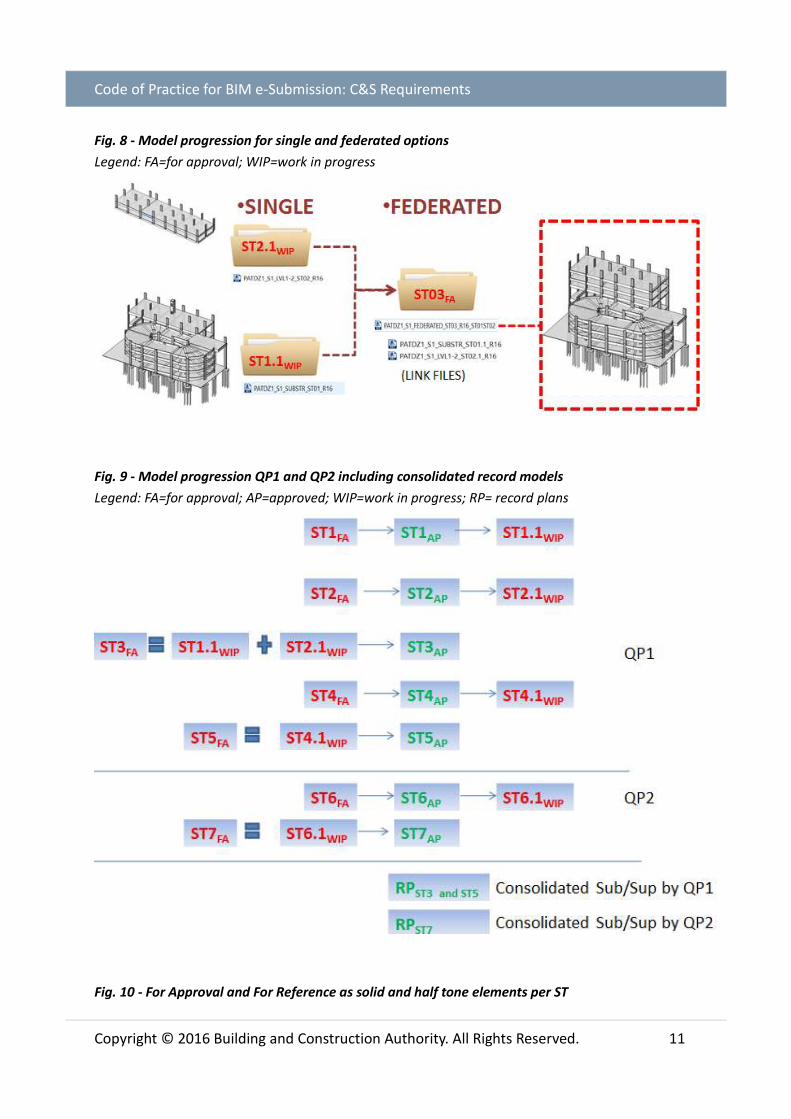
Fig. 8 - Model progression for single and federated options
Legend: FA=for approval; WIP=work in progress
Fig. 9 - Model progression QP1 and QP2 including consolidated record models
Legend: FA=for approval; AP=approved; WIP=work in progress; RP= record plans
Fig. 10 - For Approval and For Reference as solid and half tone elements per ST

Code of Practice for BIM e-Submission: C&S Requirements
Copyright © 2016 Building and Construction Authority. All Rights Reserved. 12

Code of Practice for BIM e-Submission: C&S Requirements
Copyright © 2016 Building and Construction Authority. All Rights Reserved. 13
1.2 ST Requirements
1.2.1 BCA Substructure Submission Requirement (BCA SUB/GEO Submissions)
BCA Substructure and Geotechnical Submission Requirements
(Required Views, but not limited to)
2D Views 3D Views Schedules
Site and Location
Plan*
General Notes*
Typical Details*
Non Typical Details
Floor Plans
Elevation Views
Cross &
Longitudinal
Section Views
Structural Physical
Model (PM) showing all
structural elements
Digital Terrain Model
(DTM)
Geotechnical Parameters
Dummy Object
Penetrations/Openings
Record Plans (RPP/RPF)
Schedules for all structural
elements not limited to:
Pile Schedule
Pile Cap Schedule
Retaining Wall
Schedule
Basement Slab
Schedule
Beam Schedule
Column/Wall Schedule
All 2D Views and Schedules shall be placed on sheets
Items with * can be submitted as CAD drawings as a drafting view

Code of Practice for BIM e-Submission: C&S Requirements
Copyright © 2016 Building and Construction Authority. All Rights Reserved. 14
A. Geotechnical Parameters Dummy Object
QP shall create a dummy object to represent geotechnical parameters derived from the soil
investigation (SI) report.
Dummy object shall provide a link to the bore holes (Excel sheet) used for design.
Table 4 - Borehole information (in Excel spreadsheet) PROJ_ID PROJ_NAME PROJ_
CLNT
HOLE_
ID
HOLE_
STAR
HOLE_
NATE
HOLE_
NATN
HOLE_
GL
HOLE_
FDEP
ROCK_
HEAD
ROCK_
TYPE
FORMATION
A0677-
00001-
2015
Soil Investigation
Works at No.XX XXX
Road, SG XXXXXX
Mr. XXX BH1 15/7/2015 13169.723 36010.451 6.514 45 33.5 Granite Bukit Timah
Granite
B. Substructure Schedules
Pile schedule shall be generated from objects/elements attributes and not as Excel
spreadsheets or inserted CAD files. The schedules shall include but not limited to:
a) Pile type, pile marking and pile size;
b) Working load and grade of concrete;
c) Main rebar and links;
d) Penetration length from existing ground and cut off levels indicated as Singapore
Height Datum (SHD) levels; and
e) Demolished, existing or new foundation elements.
Table 5 - Sample pile cap dimensions and rebar schedule

Code of Practice for BIM e-Submission: C&S Requirements
Copyright © 2016 Building and Construction Authority. All Rights Reserved. 15
C. Color Assignments
Coloured/Hatch/Fill Patterns can be used to show the following:
a) Dead Load values;
b) Live Load values;
c) Bore Hole zones; and
d) Existing, New, Demolished Elements as per colours specified under the CP for BIM
e-Submission: General Requirements.
Fig. 11 - Isometric view showing borehole zones
D. As-Built Pile Information
The as built pile information shall be submitted in a standardized excel spreadsheet as per
the following format:
Table 6 - Pile Excel Table

Code of Practice for BIM e-Submission: C&S Requirements
Copyright © 2016 Building and Construction Authority. All Rights Reserved. 16
1.2.2 BCA Superstructure Submission Requirements (BCA SUP Submissions)
BCA Superstructure Submission Requirements
(Required Views, but not limited to)
2D Views 3D Views Schedules
General Notes*
Typical Details*
Typical
Connections*
Non Typical
Connections
Floor Plans
Cross &
Longitudinal
Section Views
Elevation Views
Color/Hatch/Fill
Patterns
Structural Physical
Model (PM) showing all
structural elements
Penetrations/Openings
Record Plans (RPP/RPF)
Hypermodel
Schedules for all structural
elements not limited to:
Beam Schedule
Column Schedule
Wall Schedule
Slab Schedule
All 2D Views and Schedules shall be placed on sheets
Items with * can be submitted as CAD drawings as a drafting view

Code of Practice for BIM e-Submission: C&S Requirements
Copyright © 2016 Building and Construction Authority. All Rights Reserved. 17
A. Typical Details
a) Non-structural drops in slabs or beams;
b) Lintel beams for wall openings;
c) Beam elevation profiles showing cantilever, mid-span and continuous members;
reinforcement detailing;
d) Column profiles showing extent from foundation to roof including reductions; and
e) Roof rafters/purlins/tie rods connection details.
B. Other Details of Superstructure Works
a) Precast structural elements;
b) Post tension elements including tendon profile;
c) Steel or timber space frames joined by proprietary ball connections; and
d) Cross laminated timber (CLT) and glulam.
Fig. 12 - Tendons for post tension element
Fig. 13 - Exploded view of CLT structure showing Primary Load Bearing PLB objects

Code of Practice for BIM e-Submission: C&S Requirements
Copyright © 2016 Building and Construction Authority. All Rights Reserved. 18
Fig. 14 - BIM generated Floor Plans
C. Non Typical Details
Critical connections for key structural elements can be done using hybrid detailing and/or full
3D element detailing:
a) Interface between steel/timber truss terminations to supporting columns;
b) Inclined, splayed and lattice columns;
c) One-off steel bolted and/or welded connections;
d) Cantilever elements with 6m span or greater;
e) Transfer columns to beam/floor connection details; and
f) Corbel and haunch for precast elements.
Fig. 15 - Critical Elements highlighted in 3D and schedules

Code of Practice for BIM e-Submission: C&S Requirements
Copyright © 2016 Building and Construction Authority. All Rights Reserved. 19
Fig. 16 - Critical Joints showing bolted connection of steel beams to column
Fig. 17 - Highlighted structural beam with embedded rebar as attributes/properties

Code of Practice for BIM e-Submission: C&S Requirements
Copyright © 2016 Building and Construction Authority. All Rights Reserved. 20
Fig. 18 - BIM generated rebar schedule
D. Structural Detailing Options
Fig. 19 - QP three (3) options for structural detailing in native BIM

Code of Practice for BIM e-Submission: C&S Requirements
Copyright © 2016 Building and Construction Authority. All Rights Reserved. 21
E. Superstructure Element Schedule
a) Regular, up stand or down hang beam/girder rebar showing top, bottom, extra,
torsion and links;
b) Column rebar showing main, links, development/anchorage;
c) Slab rebar showing main top and bottom including additional rebar for crack
control;
d) Wall rebar showing main rebar and links; and
e) Prefabricated and pre-qualified rebar cages;

Code of Practice for BIM e-Submission: C&S Requirements
Copyright © 2016 Building and Construction Authority. All Rights Reserved. 22
1.3 Structural Requirements for Household Shelter (HS), Storey Shelter (SS) and Staircase Storey Shelter (SSS)
1.3.1 General Requirements
The design and detail of household shelter shall comply with Technical Requirements of
Household Shelter. For storey shelter and staircase storey shelter, the design and detail shall
comply with Technical Requirements for Storey Shelters.
The structural plan shall contain a site plan, the floor plans, sections and elevations of
household shelter (HS), storey shelter (SS) and staircase storey shelters (SSS) showing design
information and dimensions generated from the native BIM model. HS, SS and SSS plan shall
be indicated with the same project reference number. The abbreviation, CS should be used for
shelter structural plans respectively. For example, A9999-12345-2001-CS01 should be used for
shelter building and structural plans respectively.
For subsequent amendment submissions made to the approved shelter plans or re-submission
of shelter plans after receipt of Notice of Disapproval (NOD) issued by BCA, the plans shall be
indicated with respective plan type suffix and unique numbers in their application. For
example, if shelter building plans CS01 has been used and subsequent amendment
submissions shall be indicated with CS02.

Code of Practice for BIM e-Submission: C&S Requirements
Copyright © 2016 Building and Construction Authority. All Rights Reserved. 23
Civil Defence Shelters (HS/SS/SSS) Submission Requirements
(Required Views, but not limited to)
2D Views 3D Views Schedules
Site Plan*
General Notes*
Typical Details*
Typical
Connections*
Floor Plans
Cross and
Longitudinal
Section Views
Elevation Views
Structural Physical
Model (PM) showing the
following:
o Household Shelters
(HS)
o Storey Shelters (SS)
o Staircase Storey
Shelter (SSS)
Non Typical Connections
Penetrations/Openings
Schedules for all structural
elements not limited to:
Wall Schedule
Slab Schedule
Reinforcement
Schedule
Blast Door Schedule
Blast Hatch Schedule
Rescue Hatch Schedule
Ventilation Sleeve
Schedule
All 2D Views and Schedules shall be placed on sheets
Items with * can be submitted as CAD drawings as a drafting view
A. Site Plan
The site plan shall include the location map, general notes and standard typical details
B. General Notes
The general note shall include essential information such as material type and grade, the
standard typical detail such as steel reinforcement, curtailment marking, anchorage and
tension lapped lengths.
C. Structural Physical Model (PM)
a) Structural Physical Model of the building with HS, SS, and SSS shall include all
surrounding concrete & steel members (trellis, canopy, ledge, down hang beams,
tie beams, shielding walls etc.) which are provided and used for protection of HS,
SS, and SSS.
b) HS, SS, and SSS have to be modelled as part of the buildings.

Code of Practice for BIM e-Submission: C&S Requirements
Copyright © 2016 Building and Construction Authority. All Rights Reserved. 24
c) All ventilation sleeves, shelter door and blast door openings shall be modelled for
all HS, SS, and SSS structures.
d) Where water and gas services are located near or adjacent to HS, SS and SSS, they
shall be included as part of the 3D model.
e) Transfer structures (beams, slabs and walls), if any, supporting household storey
shelter shall be modelled. Take note the use of transfer beam is allowed for
household storey shelter only.
f) HS, SS and SSS wall and slab dimensions and reinforcement. This applies to design
of cast in-situ or precast HS, SS, and SSS.
g) Ceiling slab immediately outside the HS, SS and SSS
h) Household shelter HS, SS, and SSS slab which are integrated with pile cap or
footing.
i) Detailing of HS, SS, and SSS tower
j) Any structures above and/or surround HS, SS, and SSS shall be included as part of
the model.
D. Floor Plans for HS, SS and SSS
The floor plan generated from the model shall show the design information and dimensions
for HS, SS and SSS as follows:
a) The concrete grade and yield stress of welded steel fabric mesh and steel
reinforcement bars
b) The location and marking of HS, SS and SSS
c) The location, dimension and details of gas and water riser adjacent or near to HS,
SS and SSS
d) The external and internal dimension of HS, SS and SSS
e) The thicknesses of HS, SS and SSS wall and slab (ground, intermediate and roof
slab)
In addition, additional design information and dimensions required for SS and SSS are:
a) The distance between external face of SS or SSS entrance door and the edge of
building line
b) The thickness, dimension and steel reinforcement details of shielding wall
fronting SS or SSS entrance door
c) The clear distance between shielding wall and SS or SSS entrance door

Code of Practice for BIM e-Submission: C&S Requirements
Copyright © 2016 Building and Construction Authority. All Rights Reserved. 25
d) The thickness, dimensions and steel reinforcement details of the internal wall of
SSS
e) The thickness, dimension and steel reinforcement details of mechanical
ventilation shaft for SSS
f) The dimensions and steel reinforcement detail around the horizontal and vertical
blast hatch (for SSS) and rescue hatch (for SS)
g) The dimension and steel reinforcement detail of reinforced concrete roof
structures over the mechanical ventilation shaft above main roof level.
h) The dimensions/thickness of and reinforcement details in strengthened slab
outside and above SS/SSS door.
E. Cross Sections for HS, SS, and SSS
The sections in two directions generated from model shall include:
a) The vertical section of the entire HS, SS and SSS tower showing storey height,
dimensions and reinforcement details.
b) The horizontal section (or plan) of HS, SS and SSS wall showing steel
reinforcement, curtailment marking, anchorage and lap length. The thickness,
internal and external width and length of HS, SS and SSS shall also be indicated
(see Annex II, Figure 1a, 1b, 2a and 3a).
c) The vertical section of HS, SS and SSS wall and slab showing steel reinforcement
bar size, spacing, anchorage and lap length. The slab thickness shall also be shown
(see Annex II, Figure 1c, 1d, 2b, 2c and 2d).
d) The horizontal section (or plan) of HS, SS and SSS precast concrete door frame
showing steel reinforcement, anchorage and tension lapped lengths (see Annex II,
Figure 3a, 3b, 4a, 4b, 5a and 5c).
e) Shear link details on horizontal and vertical section of HS, SS, SSS wall and slab
(see Annex II, Figure 6).
f) The cross sectional details of openings such as the blast door opening, ventilation
openings and services penetrations including their location, size and steel
reinforcement details around them (see Annex II, Figure 7); and
g) The cross sectional details of electrical services such switches and lighting point,
switched socket outlet, telephone outlet. TV and radio outlets including their
location, size and steel reinforcement details around them (see Annex II, Figure 8).

Code of Practice for BIM e-Submission: C&S Requirements
Copyright © 2016 Building and Construction Authority. All Rights Reserved. 26
In addition sections for SSS shall include the following:
a) The cross sectional details of openings of horizontal and vertical blast hatch
including its location, size and steel reinforcement details around them;
b) The reinforced concrete roof structures over the mechanical ventilation shaft
above main roof level showing steel reinforcement bar size, spacing, anchorage
and tension lapped lengths.
F. Elevations
a) The steel reinforcement bars around the ventilation sleeve opening (see Annex II,
Figure 9)
b) The steel reinforcement bars around switches and lighting point, switched socket
outlet, telephone outlet. TV and radio outlets (see Annex II, Figure 8)
H. Schedules
a) Schedule of reinforcement bars for the HS, SS and SSS shall be provided with
types of rebar, rebar size, rebar spacing, curtailment marking to meet the
technical requirement. Table below shows schedule of reinforcement.
Table 7 - Steel reinforcement bar size and spacing for each curtailment marking
Curtailments of welded steel fabric mesh and steel bars
Curtailment marking a b e f g h
Steel Mesh D10 D10 D10 D10 D10 D10
Curtailments and steel bars
Curtailment marking c d m i
Steel bar H10-
100
H10-
100
H10-
100
H10-
100
b) Schedules of wall, column, beam and slab for the HS, SS and SSS shall be provided
with the dimension of length, width and height to meet the technical
requirement.
c) Schedules of blast door, blast hatch, rescue hatch, ventilation sleeve for the HS, SS
and SSS shall be provided with the dimension of length, width and height to meet
the technical requirement.

Code of Practice for BIM e-Submission: C&S Requirements
Copyright © 2016 Building and Construction Authority. All Rights Reserved. 27
1.4 Structural Requirements for Transit Shelter (TS)
1.4.1 General Requirements
The Qualified Person (QP) shall familiarize himself with the CD Shelter Requirements for MRT
Stations before preparing the Structural BIM submission for MRT Transit CD shelters. The
submission shall comprise native BIM 3D models, 2D plans, sections and elevations that are
illustrative with details and dimensions, to demonstrate compliance with the CD shelter
requirements. The submission shall comprehensively cover important aspects of the shelter.
Civil Defence Transit Shelters (TS) Submission Requirements
(Required Views, but not limited to)
2D Views 3D Views Schedules
General Notes*
Shelter Layout
o Floor Plans
o Cross and
Longitudinal
Section Views
o Elevation Views
Full Physical Model (PM)
showing the following:
o Shelter Structure
including Strike Points
o Entrance Areas
o CD Doors and Supporting
Structure
o Air Shafts and Bomb Pits
o Services Penetrations in
Entrance Areas
Schedules for all structural
elements not limited to:
Reinforcement
Schedule of Supporting
Structure around all CD
Doors
All 2D Views and Schedules shall be placed on sheets
Items with * can be submitted as CAD drawings as a drafting view

Code of Practice for BIM e-Submission: C&S Requirements
Copyright © 2016 Building and Construction Authority. All Rights Reserved. 28
A. TS Full Model
The 3D model shall show the entire CD shelter, and shall include the following:
a) Entrance and exit configurations;
b) Strike point location (massing elements or dummy object) ;
c) Entrance hinged doors (EHDs), or sliding doors (SLDs) and door chambers if used
in place of EHDs;
d) PT doors including any related bypass areas; and
e) Air shafts with bomb pit configurations.
B. TS Plans, Sections and Elevations
The 2D plans, sections and elevations shall illustrate clearly the following:
a) Entrance area layout leading from opening at ground level (or elsewhere) to the
EHD and PT door,
b) Strike point line and distance measured from the strike point to the EHD and PT
door,
c) Wall and slab thicknesses, in particular, those around the CD doors, and
d) Size of openings and type of services penetrations such as MCTs, puddle flanges,
etc. in walls or slabs next to or in the vicinity of the CD doors.
e) The BIM generated views shall show all associated dimensions, labels, spacing,
etc. and shall demonstrate compliance with the CD Shelter Requirements for MRT
Stations. The same shall apply if a sliding door and chamber are used in place of
the EHD.
C. TS Entrance Areas Part Model
For each entrance area leading to a CD door, a part 3D model shall be provided to illustrate
clearly the following:
a) Entrance configuration from opening at ground (or elsewhere) to the CD doors
b) Strike point line;
c) Entrance hinged door (EHD) or, sliding door and door chamber if used in place of
EHD;
d) PT door including any related bypass area; and

Code of Practice for BIM e-Submission: C&S Requirements
Copyright © 2016 Building and Construction Authority. All Rights Reserved. 29
e) Openings for services penetrations such as for air ducts, pipes, electrical cables,
trunkings and conduits in walls or slabs next to or in the vicinity of the CD doors.
D. TS Entrance Areas Plans, Sections and Elevations
The 2D plans, sections and elevations shall illustrate clearly the following:
a) Entrance area layout leading from opening at ground level (or elsewhere) to the
EHD and PT door,
b) Strike point line and distance measured from the strike point to the EHD and PT
door,
c) Wall and slab thicknesses, in particular, those around the CD doors, and
d) Size of openings and type of services penetrations such as MCTs, puddle flanges,
etc. in walls or slabs next to or in the vicinity of the CD doors.
e) The BIM generated views shall show all associated dimensions, labels, spacing,
etc. and shall demonstrate compliance with the CD Shelter Requirements for MRT
Stations. The same shall apply if a sliding door and chamber are used in place of
the EHD.
E. CD Doors and Supporting Structure Part Model
Part 3D models of the CD doors (EHD, SLD, or PT) and its supporting structure shall be
provided to illustrate clearly the following:
a) Supporting structure (walls, slabs, corbels, lintels, etc.) and its reinforcement bars
(rebar) to resist CD door line loads, including interfacing bars with door frame;
b) Door frame including fish tails, holding bars, anchor studs, etc.;
c) Top and bottom maintenance pits (for EHD);
d) Floor levels and kerbs;
e) Floor and wall hooks for chain block shackles (for EHD and/or SLD);
f) SLD chamber (if SLD is used); and
g) Openings for services penetrations such as for air ducts, pipes, electrical cables,
trunking and conduits in walls or slabs next to or in the vicinity of the CD doors.
h) Models shall show buildability and no obstructions between the rebar and the
door frame parts.

Code of Practice for BIM e-Submission: C&S Requirements
Copyright © 2016 Building and Construction Authority. All Rights Reserved. 30
F. CD Doors and Supporting Structure Plans, Sections and Elevations
The 2D plans, sections and elevations shall illustrate clearly the same as required above under
Part 3D Model but shall in addition, show all associated dimensions, rebar sizes, rebar spacing,
labels, etc. to demonstrate compliance with the CD Shelter Requirements for MRT Stations.
G. CD Doors Supporting Structure Schedule
Table 8 - Steel reinforcement bar size and spacing for each curtailment marking
Curtailments and welded steel fabric mesh and steel bars
Curtailment marking a b e f g h
Steel Mesh D10 D10 D10 D10 D10 D10
Curtailments and steel bars
Curtailment marking c d m i
Steel bar H10-
100
H10-
100
H10-
100
H10-
100
H. Air Shafts and Bomb Pits Part Model
For each air shaft and its bomb pit, a Part 3D model shall be provided to illustrate clearly the
following:
a) Air shaft configuration from opening at ground level (or elsewhere) to the plant
room interface; and
b) Bomb pit.
I. Air Shafts and Bomb Pits Plans, Sections and Elevations
The 2D plans, sections and elevations shall illustrate clearly the following:
a) Air shaft layout from opening at ground (or elsewhere) to the plant room
interface;
b) Wall and slab thicknesses;
c) Air shaft and bomb pit dimensions; and
d) The BIM generated views shall show all associated dimensions, labels, spacing,
etc. to facilitate review and shall demonstrate compliance with the CD Shelter
Requirements for MRT Stations.

Code of Practice for BIM e-Submission: C&S Requirements
Copyright © 2016 Building and Construction Authority. All Rights Reserved. 31
J. CD Technical Requirements for S10-S29 Public Shelters
Where a transit CD shelter is to be designed and built based on the CD Technical Requirements
for S10-S29 Public Shelters, or Addition and Alteration (A&A) works are carried out on such
S10-S29 Shelters, the Qualified Person (QP) shall familiarize himself with the aforementioned
document before preparing the Structural BIM submission.
The submissions shall comprise native BIM 3D models, 2D plans, sections and elevations that
are illustrative with details, dimensions, spacing, labels, schedules, material types, etc. to show
compliance with the Technical Requirements for S10-S29 Public Shelters. The level of detail
and information shown in the 2D plans, sections and elevations shall be similar as that of
traditional (2D) structural plan submissions.
The QP shall consult the Transit Shelter Engineering Department of BCA for clarification.

Code of Practice for BIM e-Submission: C&S Requirements
Copyright © 2016 Building and Construction Authority. All Rights Reserved. 32
1.5 Structural Requirements for Public Shelter (PS)
1.5.1 General Requirements
The Qualified Person (QP) shall familiarize himself with the Technical Requirements for S1-S5
Public Shelter before preparing the Structural BIM submission for public shelters. The
submission shall comprise native BIM 3D models, 2D plans, sections and elevations that are
illustrative with details and dimensions, to demonstrate compliance with the public (CD)
shelter technical requirements. The level of detail and information shown in the 2D plans,
sections and elevations shall be similar as that of traditional (2D) structural plan submissions.
The submission shall comprehensively cover important aspects of the shelter described in the
following sections.
The QP shall consult the Civil Defence Shelter Engineering Department of BCA for clarification.
Civil Defence Public Shelters (PS) Submission Requirements
(Required Views, but not limited to)
2D Views 3D Views Schedules
General Notes*
Typical Details*
Typical
Connections*
Non Typical
Connections
Floor Plans
Cross and
Longitudinal
Section Views
Elevation Views
Full Physical Model (PM)
showing the following:
o Public Shelter
o Entrance Areas
o CD Doors and
Supporting Structure
o Air Shaft
Penetrations/Openings
Schedules for all structural
elements not limited to:
Beam, Column, Slab
and Wall Schedule
Reinforcement Bars
Schedule
CD Door, Hatch,
Window Schedule
CD Valve Schedule
All 2D Views and Schedules shall be placed on sheets
Items with * can be submitted as CAD drawings as a drafting view

Code of Practice for BIM e-Submission: C&S Requirements
Copyright © 2016 Building and Construction Authority. All Rights Reserved. 33
A. PS Structure Full Model
The 3D model shall show the entire CD shelter, and shall include the following:
a) Entrance and exit configurations;
b) Imaginary line of sight to the BD;
c) Blast doors (BD), blast hatches (BH), blast fragmentation door (BFD), blast
fragmentation window (BFW) and including any related bypass areas;
d) Gas-tight doors (SSD); and
e) Air shafts.
B. PS Structure Plans, Sections and Elevations
The 2D plans, sections and elevations shall illustrate clearly the following:
a) General layout at CD levels or space associated with the CD shelter.
b) General notes stating the material type and grade (steel, concrete reinforcement
bars) use for public shelter.
c) Bounds of protection.
d) Entrance area configurations leading from the opening at ground level (or
elsewhere) to the CD doors, including imaginary line of sight to the BD and wall
and slab thicknesses.
e) Blast doors (BD), blast hatches (BH), blast fragmentation door (BFD) and blast
fragmentation window (BFW), blast valves clearances from adjacent walls, and
adjacent wall and slab thicknesses.
f) Ventilation air shafts configurations from opening at ground level (or above
ground level) to plant room areas.
g) The dimension and thickness of wall (external and internal) and slab.
h) The reinforcement details for the public shelter wall and slab shall be clearly
shown on plan, section and elevation (if any) with curtailment marking, bar size
and spacing, lapped and anchorage length. In addition, the spacing of
reinforcement bars shall be as shown below in Fig. 20, 21 and 22.
i) Schedule of reinforcement bars for the PS shall be provided with types of rebar,
rebar size, rebar spacing, curtailment marking to meet the technical
requirements. Table 9 shows the sample of schedule of reinforcement bars.

Code of Practice for BIM e-Submission: C&S Requirements
Copyright © 2016 Building and Construction Authority. All Rights Reserved. 34
C. PS Reinforcement Schedule
Table 9 - Steel reinforcement bar size and spacing for each curtailment marking
Curtailments of welded steel fabric mesh and steel bars
Curtailment marking a b e f g h
Steel Mesh D16 D16 D16 D16 D16 D16
Curtailments and steel bars
Curtailment marking c d m i
Steel bar H20-
100
H20-
100
H20-
100
H20-
100
The Reinforcement bars detail around Blast doors (BD), blast hatches (BH), blast
fragmentation door (BFD) and blast fragmentation window (BFW), blast valves and
Ventilation air shafts and other opening or recess shall be shown on plan, section and/or
elevations.
Fig. 20 - Section showing reinforcement spacing of a typical 1-storey public shelter
Fig. 21 - Section showing reinforcement spacing of a typical 2-storey public shelter

Code of Practice for BIM e-Submission: C&S Requirements
Copyright © 2016 Building and Construction Authority. All Rights Reserved. 35
Fig. 22 - Layout of a typical public shelter showing reinforcement spacing

Code of Practice for BIM e-Submission: C&S Requirements
Copyright © 2016 Building and Construction Authority. All Rights Reserved. 36
CORE INFORMATION (CI) Core Information or CI are minimum object attributes/parameters required to be embedded
for all load bearing elements. The attributes can either be pre-loaded within objects or fill up
by QP or injected via Excel to BIM link.
BOREHOLE ATTRIBUTES
GEOTECHNICAL DUMMY OBJECT
Attribute Name Sample Value Description
PROJ_ID A0677-00001-2015 Project reference no. of the ST
submission
PROJ_NAME Soil Investigation Works at
No.XXXXX Road, Singapore XXXXXX
Project Title
PROJ_CLNT Mr. XXX Project client/Data owner
HOLE ID BH1 Borehole reference identifier(as per
original borelog/AGS data)
HOLE_STAR 15/7/2015 Borehole start to drill date
HOLE_NATN 36010.451 Borehole coordinate: Northing
HOLE_NATE 13169.723 Borehole coordinate: Easting
HOLE_GL 6.514 Borehole ground level (RL)
HOLE_FDEP 45 Borehole final depth (m)
ROCK_HEAD 33.5 Rock head depth(if encountered)
FORMATION Granite Geological formation

Code of Practice for BIM e-Submission: C&S Requirements
Copyright © 2016 Building and Construction Authority. All Rights Reserved. 37
SUBSTRUCTURE ELEMENTS
PILES
Parameter Name Sample Value
Pile Mark P1
Pile Type Bored, Secant, CBP
Pile Diameter/Size 600 /500x500
Pile X-Easting 30118.210
Pile Y-Northing 29226.632
Pile As Built Length (SHD) 39.175
Pile Cut Off level (SHD) 88.975
Pile Toe Level (SHD) 49.800
Loading (kN) 1500
Material Grade C40/G550
Remarks/Status New/Existing/Demolish
Project Title Condominium
Developer ABC123
PILE CAP
Parameter Name Sample Value
Pile Cap Mark PC1
Pile Cap Type 2/3/4/5/6/8/10
Pile Cap Size 500x500
Pile Cap X-Easting 30118.210
Pile Cap Y-Northing 29226.632
Group Loading (kN) 4500
Concrete Grade C40
Remarks/Status New/Existing/Demolish
Project Title Condominium
Developer ABC123

Code of Practice for BIM e-Submission: C&S Requirements
Copyright © 2016 Building and Construction Authority. All Rights Reserved. 38
SUBSTRUCTURE SLAB
Parameter Name Sample Value
Slab Mark S1
Slab Type Composite/InSitu/Suspended
Slab Thickness 300
Slab Openings Size 1000x1000
Slab Direction 1way/2way
Slab X-Easting 30118.210
Slab Y-Northing 29226.632
Concrete Grade C40
Remarks/Status New/Existing/Demolish
RETAINING WALL
Parameter Name Sample Value
Wall Mark W1
Wall Type inSitu/Precast
Wall Thickness 300
Wall Openings Size 1000x1000
Wall X-Easting 30118.210
Wall Y-Northing 29226.632
Concrete Grade C40
Remarks/Status New/Existing/Demolish
TUNNELS
Parameter Name Sample Value
Tunnel Mark TU1
Tunnel Type Shaft/Cavern
TunnelDimensions 500
Tunnel X-Easting 30118.210
Tunnel Y-Northing 29226.632
Concrete Grade C40
Remarks/Status New/Existing/Demolish

Code of Practice for BIM e-Submission: C&S Requirements
Copyright © 2016 Building and Construction Authority. All Rights Reserved. 39
PIER AND COLUMNS
Parameter Name Sample Value
Pier Mark P1
Pier Type Column/Caisson/Abutment
Pier Dimensions 600x500
Pier X-Easting 30118.210
Pier Y-Northing 29226.632
Concrete Grade C40
Remarks/Status New/Existing/Demolish
STRUCTURAL FRAMING
Parameter Name Sample Value
Beam Mark GR1/1HB1
Beam Type Cas inSitu/Precast/Girder
Grade Beam Dimension 600x500
GB X-Easting 30118.210
GB Y-Northing 29226.632
Concrete Grade C40
Remarks/Status New/Existing/Demolish
OTHER DETAILS OF SUPERSTRUCTURE WORKS
Parameter Name Sample Value
Element Mark A1
Element Type Ground Treatment/ Slope
Protection/Soil Anchors
Element Dimensions 400x600
Element Offset 100
Element X-Easting 30118.210
Element Y-Northing 29226.632
Material Grade C40
Remarks/Status New/Existing/Demolish

Code of Practice for BIM e-Submission: C&S Requirements
Copyright © 2016 Building and Construction Authority. All Rights Reserved. 40
CRITICAL CONNECTIONS
Parameter Name Sample Value
Element Mark A1
Element Type Concrete: Rebar/Mesh/Tendon
Steel: Bolt/Anchor/Stud/Weld
Element Dimensions 400x600
Element Offset 100
Material Grade C40
Remarks/Status New/Existing/Demolish
SUPERSTRUCTURE ELEMENTS
FRAMING
Parameter Name Sample Value
Beam Mark C1
Beam Type Beam/Girder/Joist/Purlin
Beam Size 600x800
Beam Offset 200
Beam Rotation 30
Construction Method Cast in Situ/Precast
Concrete/Steel Grade C40/G550
Remarks/Status New/Existing/Demolish
COLUMNS/PEDESTAL
Parameter Name Sample Value
Column Mark C1
Column Type Square/Circular
Column Diameter/Size 600/500x500
Column Offset 200
Column Rotation 30
Construction Method Cast in Situ/Precast
Loading (kN) 1500
Concrete/Steel Grade C40/G550
Remarks/Status New/Existing/Demolish

Code of Practice for BIM e-Submission: C&S Requirements
Copyright © 2016 Building and Construction Authority. All Rights Reserved. 41
SUPERSTRUCTURE FLOOR/SLAB
Parameter Name Sample Value
Slab Mark S1
Slab Type Composite/InSitu/Suspended
Slab Thickness 300
Slab Openings Size 1000x1000
Span Direction 1way/2way
Concrete Grade C40
Remarks/Status New/Existing/Demolish
SUPERSTRUCTURE WALLS
Parameter Name Sample Value
Wall Mark W1
Wall Type InSitu/Precast
Wall Thickness 300
Wall Offset 100
Wall Openings Size 1000x1000
Material Grade C40
Remarks/Status New/Existing/Demolish
TRUSS
Parameter Name Sample Value
Truss Mark W1
Truss Type Pratt/Warren:
Bowstring/Scissors; Dual/Mono
Truss Length 20000
Truss Offset 250
Uniform Load (kN/m) 12
Point Load (kN) 5
Material Grade C40
Remarks/Status New/Existing/Demolish

Code of Practice for BIM e-Submission: C&S Requirements
Copyright © 2016 Building and Construction Authority. All Rights Reserved. 42
CIRCULATION
Parameter Name Sample Value
Circulation Mark ST1
Circulation Type Staircase/Ramps
Circulation Length 8000
Circulation Offset 250
Circulation Width 1200
Uniform Load (kN/m) 5
Material Grade C40
Remarks/Status New/Existing/Demolish
OTHER DETAILS OF SUPERSTRUCTURE WORKS
Parameter Name Sample Value
Element Mark A1
Element Type Lift/Cladding/Prestress/Post
Tension/PPVC/CLT/Glulam
Element Dimensions 400x600
Element Offset 100
Material Grade C40
Remarks/Status New/Existing/Demolish
CRITICAL CONNECTIONS
Parameter Name Sample value
Element Mark A1
Element Type Concrete: Rebar/Mesh/Tendon
Steel: Bolt/Anchor/Stud/Weld
Timber: CLT/Glulam
Element Dimensions 400x600
Element Offset 100
Material Grade C40
Remarks/Status New/Existing/Demolish

Code of Practice for BIM e-Submission: C&S Requirements
Copyright © 2016 Building and Construction Authority. All Rights Reserved. 43
CIVIL DEFENCE SHELTER ELEMENTS
HOUSEHOLD SHELTER (HS)
Parameter Name Sample Value
HS Door Opening 700x1900
Curtailment Marking a/b/c/d/e/f/g/h/i/j/k
Steel Mesh D10/13
Steel Bar H10-100
Tension Lap Length 300
Rebar Cover 35
Ventilation Sleeve Opening 150
Floor Thickness 175
Wall Thickness 300
Concrete Grade C40
Construction Method Cast in Situ/Precast
Remarks/Status New/Existing/Demolish
STOREY SHELTER (SS)
Parameter Name Sample Value
SS Door Net Opening 1000x1900
Curtailment Marking a/b/c/d/e/f/g/h/i/j/k
Steel Mesh Size D10/13
Steel Bar Spacing H10-100
Tension Lap Length 300
Rebar Cover 35
Ventilation Sleeve Opening 150
Floor Thickness 175
Wall Thickness 300
Material Grade C40
Construction Method Cast in Situ/Precast
Remarks/Status New/Existing/Demolish

Code of Practice for BIM e-Submission: C&S Requirements
Copyright © 2016 Building and Construction Authority. All Rights Reserved. 44
STAIRCASE STOREY SHELTER (SSS)
Parameter Name Sample Value
SSS Door Net Opening 1000x1900
Curtailment Marking a/b/c/d/e/f/g/h/i/j/k
Steel Mesh Size D10/13
Steel Bar Spacing H10-100
Tension Lap Length 300
Rebar Cover 35
Ventilation Sleeve Opening 150
Floor Thickness 200
Wall Thickness 300
Stair Thickness 200
Material Grade C40
Construction Method Cast in Situ/Precast
Remarks/Status New/ Existing/Demolish
TRANSIT SHELTER (TS)
Parameter Name Sample Value
Structural Element Slab, Wall, Beam, Column
Shelter Type S1, S2, S3, S4, S5
Minimum Dimension 400, 500, 600
Steel Mesh Size D10/13
Steel Bar Spacing H10-100
Tension Lap Length 300
Tension Anchorage Length 300
Rebar Cover 35
Ventilation Sleeve Opening 150
Floor Thickness 200
Wall Thickness 300
Stair Thickness 200
Material Grade C40
Construction Method Cast in Situ/Precast
Remarks/Status New/Existing/Demolish

Code of Practice for BIM e-Submission: C&S Requirements
Copyright © 2016 Building and Construction Authority. All Rights Reserved. 45
PUBLIC SHELTERS (PS)
Parameter Name Sample Value
Door Opening 700x1900
Curtailment Marking a/b/c/d/e/f/g/h/i/j/k
Steel Mesh D10/13
Steel Bar H10-100
Rebar Cover 35
Ventilation Sleeve Opening 150
Floor Thickness 175
Wall Thickness 300
Stair Thickness 200
Material Grade C40
Construction Method Cast in Situ/Precast
Remarks/Status New/Existing/Demolish

Code of Practice for BIM e-Submission: C&S Requirements
Copyright © 2016 Building and Construction Authority. All Rights Reserved. 46
COLOUR CODES
The following colours are to be used for superstructure load bearing elements for submission.
The colours refer to object outline and not on element face. BCA will issue default BCA
templates for all major BIM authoring software to automate the colour assignment via
element or category filters.
Critical Key Elements
Element Category Colour Red Green Blue
Cantilever Elements (>6m) 0 0 255
Long Span Structure (>15m) 0 255 0
Transfer Structures 225 0 0
Permanent ERSS 210 180 140

Code of Practice for BIM e-Submission: C&S Requirements
Copyright © 2016 Building and Construction Authority. All Rights Reserved. 47
DEFINITION OF TERMS
CO means Construction Stage where the building works are carried by
the contractor
DD means Detailed Design Stage equivalent to ST and CS submissions
Hypermodel refers to combined part 3D cross section geometry and
annotations
Non Typical Details are defined as details other than Typical Details
RP means Record Plans, production of record models/record plans on
or before obtaining TOP/CSC
SFL means Structural Floor Level
SHD means Singapore Height Datum
Substructure (SUB) refers to all load bearing structural elements below ground
Superstructure (SUP) refers to all load bearing structural elements above ground
Typical Details are defined as repeating details affecting more than 50% of that
similar element

Code of Practice for BIM e-Submission: C&S Requirements
Copyright © 2016 Building and Construction Authority. All Rights Reserved. 48
ANNEX I. REQUIREMENTS FOR CIVIL DEFENCE SHELTERS
Project Reference No: _________________________
Approval granted herein is with respect to civil defence shelter
works only
BUILDING AND CONSTRUCTION AUTHORITY
APPROVED UNDER SECTION 5 / SECTION 5A OF THE
BUILDING CONTROL ACT (CAP 29)
____ Sheet of ____
100 mm
120 m
m
Standard Approval Stamp for Civil Defence Shelter Plans

Code of Practice for BIM e-Submission: C&S Requirements
Copyright © 2016 Building and Construction Authority. All Rights Reserved. 49
I, _______________________, hereby submit the detailed civil defence
shelter plans *(and design calculations) prepared by me and certify that:
(a) the preparation of these civil defence shelter plans are in accordance
with the Building Control Regulations; and
(b) the civil defence shelter works shown on these plans are designed in
accordance with the shelter technical requirements.
2 Total number of civil defence shelter plans submitted: ________
and total number of pages of design calculations: ________.
________________________________ _________________
Qualified Person’s Signature and Stamp Date
* Delete where not applicable
Standard Certification for Civil Defence Shelter Plans

Code of Practice for BIM e-Submission: C&S Requirements
Copyright © 2016 Building and Construction Authority. All Rights Reserved. 50
ANNEX II. FIGURES FOR HS, SS AND SSS

Code of Practice for BIM e-Submission: C&S Requirements
Copyright © 2016 Building and Construction Authority. All Rights Reserved. 51
FIGURE 1c. SECTION A-A

Code of Practice for BIM e-Submission: C&S Requirements
Copyright © 2016 Building and Construction Authority. All Rights Reserved. 52
FIGURE 1d. SECTION B-B

Code of Practice for BIM e-Submission: C&S Requirements
Copyright © 2016 Building and Construction Authority. All Rights Reserved. 53
FIGURE 2a. PLAN OF STAIRCASE STOREY SHELTER
TABLE 2a. STEEL REINFORCEMENT BAR SIZE AND SPACING FOR EACH CURTAILMENT MARKING (SAMPLE TABLE)
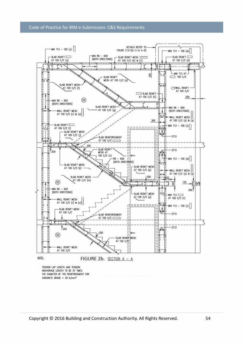
Code of Practice for BIM e-Submission: C&S Requirements
Copyright © 2016 Building and Construction Authority. All Rights Reserved. 54

Code of Practice for BIM e-Submission: C&S Requirements
Copyright © 2016 Building and Construction Authority. All Rights Reserved. 55

Code of Practice for BIM e-Submission: C&S Requirements
Copyright © 2016 Building and Construction Authority. All Rights Reserved. 56
FIGURE 3a. PLAN OF PRECAST HS, SS OR SSS DOOR FRAME (TYPE1)
TABLE 3a. STEEL REINFORCEMENT BAR SIZE AND SPACING FOR EACH CURTAILMENT MARKING (SAMPLE TABLE)

Code of Practice for BIM e-Submission: C&S Requirements
Copyright © 2016 Building and Construction Authority. All Rights Reserved. 57
FIGURE 3B. PLAN OF PRECAST HS, SS or SSS DOOR FRAME (TYPE 1)

Code of Practice for BIM e-Submission: C&S Requirements
Copyright © 2016 Building and Construction Authority. All Rights Reserved. 58
FIGURE 3c. PLAN OF PRECAST HS, SS or SSS DOOR FRAME (TYPE 1)

Code of Practice for BIM e-Submission: C&S Requirements
Copyright © 2016 Building and Construction Authority. All Rights Reserved. 59
FIGURE 4a. PLAN OF PRECAST HS, SS or SSS DOOR FRAME (TYPE 2)

Code of Practice for BIM e-Submission: C&S Requirements
Copyright © 2016 Building and Construction Authority. All Rights Reserved. 60
FIGURE 4b. PLAN OF PRECAST HS, SS or SSS DOOR FRAME (TYPE 2)

Code of Practice for BIM e-Submission: C&S Requirements
Copyright © 2016 Building and Construction Authority. All Rights Reserved. 61
FIGURE 4c. PLAN OF PRECAST HS, SS or SSS DOOR FRAME (TYPE 2)

Code of Practice for BIM e-Submission: C&S Requirements
Copyright © 2016 Building and Construction Authority. All Rights Reserved. 62
FIGURE 5a. PLAN OF PRECAST HS, SS or SSS DOOR FRAME (TYPE 3)

Code of Practice for BIM e-Submission: C&S Requirements
Copyright © 2016 Building and Construction Authority. All Rights Reserved. 63
FIGURE 5b. PLAN OF PRECAST HS, SS or SSS DOOR FRAME (TYPE 3)

Code of Practice for BIM e-Submission: C&S Requirements
Copyright © 2016 Building and Construction Authority. All Rights Reserved. 64
FIGURE 5c. PLAN OF PRECAST HS, SS or SSS DOOR FRAME (TYPE 3)

Code of Practice for BIM e-Submission: C&S Requirements
Copyright © 2016 Building and Construction Authority. All Rights Reserved. 65
FIGURE 5d. PLAN OF PRECAST HS, SS or SSS DOOR FRAME (TYPE 3)

Code of Practice for BIM e-Submission: C&S Requirements
Copyright © 2016 Building and Construction Authority. All Rights Reserved. 66
FIGURE 6. SHEAR LINKS DETAILS FOR for HS, SS and SSS WALL AND SLAB

Code of Practice for BIM e-Submission: C&S Requirements
Copyright © 2016 Building and Construction Authority. All Rights Reserved. 67
FIGURE 7. STEEL REINFORCEMENT BAR DETAIL FOR HS, SS SND SSS DOOR OPENING

Code of Practice for BIM e-Submission: C&S Requirements
Copyright © 2016 Building and Construction Authority. All Rights Reserved. 68
FIGURE 8. STEEL REINFORCEMENT BAR DETAILS FOR SWITCHED OUTLET, TC, RADIO AND
POWER POINT

Code of Practice for BIM e-Submission: C&S Requirements
Copyright © 2016 Building and Construction Authority. All Rights Reserved. 69
FIGURE 9. STEEL REINFORCEMENT BAR DETAILS AROUND VENTILATION SLEEVE AND WALL
RECESSES

Code of Practice for BIM e-Submission: C&S Requirements
Copyright © 2016 Building and Construction Authority. All Rights Reserved. 70
LIST OF TABLES
Table 1 - File Naming Conventions for ST Submissions
Table 2 - File Naming Codes
Table 4 - Borehole information (in Excel spreadsheet)
Table 5 - Sample pile cap dimensions and rebar schedule
Table 6 - Pile Excel Table
Table 7 - Steel reinforcement bar size and spacing for each curtailment marking
Table 8 - Steel reinforcement bar size and spacing for each curtailment marking
Table 9 - Steel reinforcement bar size and spacing for each curtailment marking
LIST OF FIGURES
Fig. 1 - View List for Approval and for Reference
Fig. 2 - Sample Cover Page with Title Blocks
Fig. 3 - File Naming Example
Fig. 4 - Site layout showing reduced annotations at L1
Fig. 5 - ST plan submission in stages indicating a consolidated substructure and
superstructure BIM files before TOP/CSC
Fig. 6 - Model progression for ST1 and ST2.
Fig. 7 - Model progression for amendment submissions for approved ST
Fig. 8 - Model progression for single and federated options
Fig. 9 - Model progression QP1 and QP2 including consolidated record models
Fig. 10 - For Approval and For Reference as solid and half tone elements per ST
Fig. 11 - Isometric view showing borehole zones
Fig. 12 - Tendons for post tension element
Fig. 13 - Exploded view of CLT structure showing Primary Load Bearing PLB objects
Fig. 14 - BIM generated Floor Plans
Fig. 15 - Critical Elements highlighted in 3D and schedules
Fig. 16 - Critical Joints showing bolted connection of steel beams to column
Fig. 17 - Highlighted structural beam with embedded rebar as attributes/properties
Fig. 18 - BIM generated rebar schedule
Fig. 19 - QP three (3) options for structural detailing in native BIM
Fig. 20 - Section showing reinforcement spacing of a typical 1-storey public shelter
Fig. 21 - Section showing reinforcement spacing of a typical 2-storey public shelter

Code of Practice for BIM e-Submission: C&S Requirements
Copyright © 2016 Building and Construction Authority. All Rights Reserved. 71
Fig. 22 - Layout of a typical public shelter showing reinforcement spacing
CODE OF PRACTICE FOR BIM E-SUBMISSION SERIES
This section is part of the Code for Practice for BIM e-Submission series:
Code of Practice for BIM e-Submission
A. General Requirements
B. Architectural Requirements
C. Civil & Structural (C&S) Requirements
D. Mechanical, Electrical & Plumbing (MEP) Requirements
Building and Construction Authority
52 Jurong Gateway Road
#11-01, Singapore 608550
www.bca.gov.sg
For more information and feedback on
the Code of Practice for
Building Information Modelling series,
please visit the CORENET website:
www.corenet.gov.sg
All documents related to BIM e-Submission can be downloaded from the CORENET
website:
o Code of Practice for BIM e-Submission
o BIM e-Submission Templates
o BIM e-Submission Template Guides
https://www.corenet.gov.sg/general/building-information-modeling-(bim)-e-
submission.aspx

Code of Practice for BIM e-Submission: C&S Requirements
Copyright © 2016 Building and Construction Authority. All Rights Reserved. 72