oculus rift control of a mobile robot - diva portal754499/fulltext01.pdf · oculus rift control of...
TRANSCRIPT

Oculus Rift Control of a Mobile Robot
Providing a 3D Virtual Reality Visualization for Teleoperationor
How to Enter a Robots Mind
DANIEL BUG
Master’s Thesis at CSCSupervisor: John FolkessonExaminer: Danica Kragic
TRITA xxx yyyy-nn


AbstractRobots are about to make their way into society. Whether one speaksabout robots as co-workers in industry, as support in hospitals, in elderlycare, selfdriving cars, or smart toys, the number of robots is growing con-tinuously. Scaled somewhere between remote control and full-autonomy,all robots require supervision in some form. This thesis connects theOculus Rift virtual reality goggles to a mobile robot, aiming at a power-ful visualization and teleoperation tool for supervision or teleassistance,with an immersive virtual reality experience. The system is tested ina user study to evaluate the human-robot interaction and obtain anintuition about the situation awareness of the participants.

Contents
1 Introduction 11.1 Problem statement . . . . . . . . . . . . . . . . . . . . . . . . . . . . 51.2 Contributions of the thesis . . . . . . . . . . . . . . . . . . . . . . . . 51.3 Visions . . . . . . . . . . . . . . . . . . . . . . . . . . . . . . . . . . . 61.4 Outline . . . . . . . . . . . . . . . . . . . . . . . . . . . . . . . . . . 6
2 Related Work 92.1 Systems designed for teleoperation . . . . . . . . . . . . . . . . . . . 92.2 Human-Robot Interaction . . . . . . . . . . . . . . . . . . . . . . . . 102.3 Visualization . . . . . . . . . . . . . . . . . . . . . . . . . . . . . . . 102.4 Looking into the Crystal Ball . . . . . . . . . . . . . . . . . . . . . . 11
3 System Components and Background 133.1 Oculus Rift . . . . . . . . . . . . . . . . . . . . . . . . . . . . . . . . 13
3.1.1 Stereo Vision . . . . . . . . . . . . . . . . . . . . . . . . . . . 143.1.2 Candy for the Eyes . . . . . . . . . . . . . . . . . . . . . . . . 16
3.2 Mobile Robot: Scitos G5 . . . . . . . . . . . . . . . . . . . . . . . . . 183.3 Robot Operating System . . . . . . . . . . . . . . . . . . . . . . . . . 183.4 Ogre3D Rendering Engine . . . . . . . . . . . . . . . . . . . . . . . . 20
3.4.1 Main System Components . . . . . . . . . . . . . . . . . . . . 203.4.2 Meshes and Textures . . . . . . . . . . . . . . . . . . . . . . . 223.4.3 Rendering Pipeline . . . . . . . . . . . . . . . . . . . . . . . . 223.4.4 Geometry, Vertex and Fragment Shaders . . . . . . . . . . . . 24
3.5 Object Oriented Input System . . . . . . . . . . . . . . . . . . . . . . 25
4 Implementation 274.1 The Fundament . . . . . . . . . . . . . . . . . . . . . . . . . . . . . . 274.2 Building the Environment . . . . . . . . . . . . . . . . . . . . . . . . 28
4.2.1 Bandwidth considerations . . . . . . . . . . . . . . . . . . . . 284.2.2 Snapshot Reconstruction from Textures and Shaders . . . . . 294.2.3 Connection to ROS . . . . . . . . . . . . . . . . . . . . . . . . 32
4.3 Taking Action . . . . . . . . . . . . . . . . . . . . . . . . . . . . . . . 344.4 Overview . . . . . . . . . . . . . . . . . . . . . . . . . . . . . . . . . 36

5 Experimental evaluation 415.1 Experimental setup . . . . . . . . . . . . . . . . . . . . . . . . . . . . 425.2 User Study . . . . . . . . . . . . . . . . . . . . . . . . . . . . . . . . 435.3 Results . . . . . . . . . . . . . . . . . . . . . . . . . . . . . . . . . . . 44
5.3.1 Measures . . . . . . . . . . . . . . . . . . . . . . . . . . . . . 445.3.2 Subjective Feedback I . . . . . . . . . . . . . . . . . . . . . . 455.3.3 Subjective Feedback II . . . . . . . . . . . . . . . . . . . . . . 475.3.4 Discussion . . . . . . . . . . . . . . . . . . . . . . . . . . . . . 47
6 Summary and Conclusion 51
7 Future Work 53
Bibliography 57
A 61


AcknowledgmentsCredits go to the CVAP and CAS institute at KTH. In particular, I want to thankmy supervisor John Folkesson for advice and guidance, as well as Mario Romero,who inspired the vision-part of this work and kept an eye on some formalities in thebeginning, and Patric Jensfelt, who contributed in many discussions and progressmeetings.From the team of teaching assistants I wish to thank Rasmus Göransson for hishelp with my first steps with the rendering engine and shader programs, Rares A.Ambrus for his help during the user-study and, together with Nils Bore, for the helpwith the robot hardware and advice on ROS.Final words of thanks go to the participants of the study for their time and con-structive feedback.


Chapter 1
Introduction
This thesis project "Oculus Rift Control of a Mobile Robot" connects the OculusRift virtual reality goggles to a Metralabs Scitos A5 mobile robot. The projectimplements the initial platform to render the 3D environment in stereo and enablethe user to control the robot in the real world based on its virtual representation.As an introduction, this section will familiarize the reader with the necessary terms,definitions and ideas to understand the motivation behind the project and possibledevelopment in the future.
1. A robot may not injure a human being or, through inaction,allow a human being to come to harm.
2. A robot must obey the orders given to it by human beings,except where such orders would conflict with the First Law.
3. A robot must protect its own existence as long as such protec-tion does not conflict with the First or Second Law.
- "Three Laws of Robotics", Isaac Asimov
Starting this thesis with the "Three Laws of Robotics" and thus, a link to a 1942science-fiction novel by Asimov, the huge step is indicated that robots have takenfrom pure elements of fiction, to elements of modern industry environments, lab-oratories, hospitals and even modern homes. In that sense, robots are becomingincreasingly common [1]. As nearly every technological object tends to becomesmart and connected, it is necessary to differentiate between different types or ideasof robots. The definition of a robot as a smart object is rather weak, since it in-cludes every modern cellphone or TV. Today’s vehicles on the other hand, with theirmultiple assistance systems for driving, navigation and safety possess a certain levelof autonomy, since some devices actively change parameters or decide about theapplication of the drivers control decision. Defining a robot as a smart autonomous
1

CHAPTER 1. INTRODUCTION
machine is sufficient to filter out most relevant devices and puts emphasis on theidea that a robot should have autonomy and mobility. Aiming at the science-fictionorigin of the idea, a robot can also be defined as an artificial human being. Thoughthere is a lot of research in this area, this definition is clearly too strict in the sensethat it puts constraints on the appearance and design, which contradicts the com-mon use of the term for machines - robots - in industry. For most robots the seconddefinition will be the most suitable of these three, though the term remains fuzzyand depending on its context. With the ongoing advances in computational powerand thus, capabilities in artificial intelligence and smart technology, the lines be-tween definition will blur even more, as smart-phones turn to sensors and databasesfor connected devices, or make it possible to remotely operate arbitrary machinesvia app-interfaces.
Robot Applications
Robots are applied for various tasks in an increasing number of fields. One of thehistorically earliest examples is the industry sector. Production relies on large ma-chine lines, which along with the rising availability of computational power, havebecome smart enough to count as robots. Even the last definition as artificial humanbeing might be fulfilled, if a production line robot is seen as a strong automatizedreplacement for a worker, or just the task related body part, e.g. an arm. Usually,these robots are applied where a task is heavy, discomforting, or dangerous for ahuman. While they can provide high forces and moments, the level of autonomyand mobility is low, due to specialization on a single task.In medicine, robots are used or will be used in the near future in surgery, as aninterface to improve the accuracy of the surgeon, ease the control of other techno-logical equipment, e.g. medical lasers, and eventually one day to enable specialistsfrom the other end of the world to help patients in far away places, without thenecessity of time consuming travel [2]. Related to this thesis is the field of servicerobots, expected to take an important role in health care, elderly care and home as-sistance [1]. Due to the increased need for employees in these sectors the assistancethrough robots will allow the personnel to focus on the care, instead of minor, yettime consuming tasks.Transportation might change in the future to become a robotics field, where auto-nomous cooperative vehicles, or e.g., railways in [3], ensure an optimal traffic flowand resolve problems like traffic-jams or the security-risk arising from drivers, whofollow their schedule until exhaustion.Military is another stakeholder in robotics. In recent conflicts, the first missions withunmanned drones have been executed, for territorial investigation and as ’unmannedcombat air vehicle’. Especially in warfare, the idea of sending machines instead ofsoldiers into hostile territory is a way to minimize the own risk of combat losses, butat the same time raises difficult ethical concerns. Well known psychological studies,
2

like the Milgrim experiment [4], show the willing obedience of subjects to ordersgiven by an authority, which takes the responsibility from them. Likewise, individ-ual bounds tend to vanish, if the contact between two subjects is depersonalizedor entirely anonymized through technology. A common phenomenon that can beobserved everyday in the amount of bullying, insulting, or harassing commentary inthe world-wide web. Note that remotely controlled drones combine both, an oper-ator who can shift his responsibility to the higher rank person in charge and theanonymity of the ’unmanned air combat vehicle’ - a mixture that, in the authorsopinion, in a very dangerous way, reduces the risks a technologized participant hasto expect from a fight. Another area of military related research focuses on groundvehicles for exploration and transport. Such technologies can as well be appliedin civil tasks, e.g. the surveillance of company property, or in public security, e.g.to scout collapsed buildings and find trapped victims. A pure example of a rescuerobot is given in [5].Entertainment is the final example mentioned here. In this category, a uniform classi-fication of properties is impossible, since robots of almost all types are present: fromrobot pets [6], over remotely controlled quadrucopters, the "LEGO Mindstorms" [7]products, to instrument-playing human-like robots. It is estimated that the home-consumer market will in the future be a strong growing sector within robotics [8].Which of the above examples of robot applications suit the "Three Laws of Robotics"is left for the reader to decide.
Autonomy and Visualization
Apart from the tasks they perform, robots can be classified in terms of their levelof autonomy. The scale reaches from remotely controlled robots, to full autonomyup to the task level. Commonly, the level of autonomy is directly related to theapplication layer on which the user interacts with the machine and complexity isgrowing with the level of autonomy. The use cases that are placed between thenamed extremes will be called mixed-initiative control, i.e. the robot keeps a certainautonomy, but the user can influence decisions on several actions.In the case of full autonomy, the robot has to be able to handle itself in all (un)foreseensituations. This implies that, technically speaking, all control loops on all systemlevels up to the task have to be closed by the software running the robot. For alllower levels of autonomy, the user is able to interfere with the program and hence,takes an active role in at least one system loop. A meaningful user input thereforerequires knowledge about the machine state on the user side.Vision is probably the most advanced sense of human beings and therefore a well-suited interface to the machine, if it is addressed in the right way. Vision plays alarge role in human perception, since it combines spatial, brightness and color in-formation simultaneously and has a higher reach than the sense of touch, taste or(in many cases) even hearing - things that should be utilized by a good visualiza-
3

CHAPTER 1. INTRODUCTION
FullAutonomy
NoAutonomy
Task
Navigation
Controller Level
Hardware Input Level
Figure 1.1: Scale of robot autonomy levels linked to different robot-application layers(inspired from [9]). The robot posses no autonomy, if the user controls the hardwareinputs. With each layer of control that is closed on the robot, the machine gainsautonomy. If the user interaction is only on the level of specifying a task, almostfull autonomy is reached.
tion. While in the past visualization usually meant viewing large sets of parametersdisplayed on a screen and updated occasionally, the trend seems to go towards (live-)feedback from cameras and sensors mounted on the robot - [10, 11, 12, 13, 14, 15]for instance, use visual sensor feedback. Seeing the robot and its surrounding, ora virtual representation of it, is immensely improving what is called the situationawareness of the user. A number of projects research different methods to optimizethe user interaction with robots. Optical feedback itself can be subdivided furtherby the users influence on the view point. While a mounted camera may provide agood quality video stream, its fix position can lead to occlusions and creates theneed for the user to rearrange the robot position, where in many cases an adaptionof the viewpoint would be sufficient. For example, the distance to an obstacle aheadis easily seen in a side-view, but can be hard to estimate from a 2D video. Recentmethods take 3D measurements with lasers of kinect-like devices into account andgenerate 3D scenarios, which allows a free viewpoint selection.Visualization is a powerful tool and provides, if applied appropriately, a natural in-terface from the machine to the user. In this context, the term ’natural’ aims atthe intuitive use of the interface without the necessity for extensive explanation ortraining. Looking at common human-to-machine interface, e.g. keyboard, mouse,joystick etc. the term natural interface extends to the avoidance of physiologicallydiscomforting, stressing or exhausting poses. Although it is most common, the key-board does in this definition not count as a natural interface.On the most recent gaming conventions, known vendors as well as start-ups haveannounced their efforts to develop hard- and software for highly convincing virtualreality experiences. The most famous examples are the Oculus Rift Virtual Realitygoggles [16] and Sonys ’Project Morpheus’ [17]. Both are expected to be supportedby common gaming platforms within a few years. Virtual Reality (VR) seeks torealize the above concepts of situation awareness through visual and audio stimu-lus and natural interfaces in order to let the user dive deep into the fictive game
4

1.1. PROBLEM STATEMENT
environments and actually embody him in the game rather than guiding an avatarin first-person, or third person view. Enthusiastic reactions by the gaming commu-nity promise large commercial interest. The acquisition of the Oculus VR start-upby Facebook in March 2014 for 2 Mrd. US Dollar indicates the high expectationson virtual reality. Googles project ’Tango’, which develops a smart phone able tocollect and analyze 3D data, may as well illustrate the rising interest in the thirdspatial dimension.
1.1 Problem statementThe prognosis of an increasing number of robots in all-day situations, see [1] , impliesthe demand for natural interfaces and intuitive ways to understand and to teachhow these complex machines work. This should include an understanding for thelimitations and their perception as well. Modern visualization techniques are thekey to make the challenges in robotics perceivable for everyone, independent oftheir experience. The CVAP/CAS Institute at KTH is researching in the area ofautonomous robotics as part of the STRANDS project [18]. With the MetralabsScitos A5 robot at the institute the goal is to build a system capable to performenduring tasks, self-organized and with a high level of autonomy. At its current state,the machine still needs supervision and eventually requests help while navigatingthrough the institute and solving predefined tasks, usually exploration.A simple visualization is given with the ROS program ’rviz’. It allows to displayvarious state variables on the robots built-in screen and accepts even a few userinputs. This thesis project aims to extend the accessibility of the robot by a virtualreality interface, with similar functionality.
1.2 Contributions of the thesisThe main idea of this work, as illustrated in Figure 1.2 is to connect Oculus RiftVR goggles to the mobile robot in order to visualize the robot’s 3D world-modeland to control the robot on a task level from inside the virtual reality. The user-to-machine interface will be a standard gamepad, allowing a free navigation in theVR plus a small set of commands to interact with the robot. It will enable theuser to steer the robot to points-of-interest in the VR, e.g. to guide the robot tounexplored positions, improve the visualization details, remove occlusions, or similar.The integration of the platforms: Ogre3D engine, Oculus Rift SDK and the RobotOperating System (ROS) will form the application fundament for the visualization.Expected challenges are the decoupling between 3D data messaging and processingand the rendering pipeline. The decoupling is essential to obtain a reasonably highframe rate and hence, smooth visualization and player movement in the 3D VR onthe one side and an efficient handling of the large amount of data on the other side.The system should be modular and its components reusable, so that the developmentcan be continued in future projects easily.
5

CHAPTER 1. INTRODUCTION
Mobile Robot"ROSIE"
Virtual 3DEnvironment 3D data
wirelessrendering
commandinterface
U S E R
head orientation
Figure 1.2: A first sketch of the system.
1.3 Visions
Although the ideas mentioned in this section will not be part of the actual imple-mentation, they give an impression on possible future development, but in the sameway they are an important part of the thesis’ motivation. In its basic form, thesystem represents a teleassistance interface for the robot. The assistance is purelyin terms of navigation and mostly interesting for exploration tasks, but could beextended to other areas, too. For example, an interaction of the user and a robotavatar in the VR environment could be the interface for a virtual machine trainingplatform.The 3D visualization is of course not limited to the robot state and 3D snapshots ofthe scenery either. Possible program extensions could merge other information intothe VR and enable the user to evaluate and double-check the data, which the robotuses for its algorithms. Since this option is eventually prevented by costly bandwidthrequirements (considering the desirable wireless connection between robot and visu-alization PC), a subset of the robot data might be more interesting.In different research projects, e.g. [19], the robot is trained to recognize and trackpeople during his exploration. Such activities in the surrounding might be data,which is worth displaying in the VR. If activity is visualized in a smart way, thetime of occurrence can be included, too, enabling the user to not only see the virtualenvironment as static, but as a dynamic and alive world. Considering that, despitethe gathering of 3D data, the robot is moving on a 2D plane, the third dimensioncould be used to visualize activity and the time dimension included in it.
1.4 Outline
This report presents the project in a straight forward, standard way to the reader.Chapter 1 introduced a number of terms and definitions and sketched the idea of thework. In the following chapter, Chapter 2, the thesis will be placed in its scientificcontext, by looking at the related research in the fields of teleoperation, human-machine interaction (human-robot interaction) and visualization. Similar projectsare referenced, briefly summarized and finally, some outlook is given, on what mightbe part of the future of the project.
6

1.4. OUTLINE
Afterwards, Chapter 3 and Chapter 4 cover the background information, introducethe system components and show how they are integrated into the implementation.Especially the fourth chapter reveals several tricks in the implementation, which arecrucial in order to obtain satisfying results.Chapter 5 contains a description of the experiment, which was performed to evaluatethe tool. Detailed information is given on the setup, the user study, the results andtheir discussion.The report is concluded with a summary and conclusion in Chapter 6 and concretesuggestions for future projects are given in Chapter 7.
7


Chapter 2
Related Work
This chapter will give the reader the context to understand and evaluate the connec-tion and relevance of the different aspects of this thesis. Since robots are becomingmore and more common, the background knowledge of operators changes. The robotleaves the computer scientific laboratories and is integrated into the regular workenvironment of people who are non-specialists in the field of robotics. It is thereforeinteresting to look at several public-scientific sources, as well.
2.1 Systems designed for teleoperation
In [15], Okura et al. propose a system for the teleoperation of a mobile robot viaaugmented reality, which is very close to the idea of this thesis’ work. It features ahead-mounted display for visualization, a gamepad for control and a mobile robot,which is equipped with depths cameras and one omnidirectional camera. The paperdiffers in the degree of autonomy of the system. The robot is strictly user controlledand designed for teleoperation, while for this thesis, the (long-term) goal is to keepa high autonomy in the navigation and planning of the robot. Martins and Venturause a similar system in [14], where the head movement is used as control input tothe robot. Ferland et al. apply a 3D laser scanner in [20] and merge scene snapshotsinto a 3D projection on screen, to enhance the operators situation awareness. Thepaper includes a short study with 13 participants for evaluation.A historical perspective on the development of exploration robots, such as the marsrovers, is given by Nguyen et al. in [21]. A focus is kept on the benefits of visu-alization tools and the advantage of user interaction on a task level rather thandirect control of the robot. The authors point to the constraints on the achievableperformance in a directly controlled application due to communication delays. Forextraterrestrial applications, a direct control-link is usually even impossible.Further material on the teleoperation of vehicles was published by Fournier et al.in [13], Zhang et al. in [12] and Alberts in [11]. All three emphasize the importanceof visualization as the main factor for situation awareness. Additionally, [13] and
9

CHAPTER 2. RELATED WORK
[11] give examples of how a good visualization can be achieved. While in [13] animmersive augmented reality chamber (CAVE) is used, different rendering methods,i.e. point-clouds, triangulation and quad visualization, are compared in [11]. In [22]by Huber et al., the visualization for remote control of a vehicle is evaluated in termsof its real-time capability.In the paper [10] by Lera et. al., a system for teleoperation is presented, which usesaugmented reality, i.e., including additional helpful information into the VR, to im-prove the orientation and user-comfort. Their evaluation yields that the supportivelandmarks and hint indeed easen the process of finding through a test-parkour.
2.2 Human-Robot InteractionAnother important sector in robotics is human health care, especially for older peopleand people suffering from physical disorders. Although functionality for teleoper-ation is still very interesting, e.g. to guide the robot through a difficult situation,improve the clients security, or simply as an interface to establish a telepresence con-tact to a doctor or nurse, as suggested by Hashimoto et al. in [23], the focus changestowards the question how to provide comfortable and safe human-robot interfaces.As pointed out earlier, robots are on their way into society. For applications insurveillance, military, or research, it might be feasible to assign the operation of therobots to trained employees, but the more common robots become in civil applica-tions, for example rescue, health-care, medicine, or even entertainment, the strongerthe need for an intuitive understanding of the machine’s functionality and limita-tion. In [24], Anderson et al. propose an intelligent co-pilot as an architecture forembedded security functionality in cars, which keeps the restrictions to the user-comfort to a minimum. Their aim is to close the gap between fully human-operatedvehicles, in which the security systems are merely visual or acoustic warnings, andfully autonomous vehicles, which take away the freedom of the driver. The mainidea is to let the security system define safe corridors, in which the user may actfreely. In [25] by Valli, an appeal is made to scientists, programmers and develop-ers to think more about the way people actually interact (with each other) and lettheir observations guide the design of human-machine interfaces. The study [26] byGoodrich on human-robot interaction, gives a broad overview on robot application,interfaces, requirements and current challenges in the field of HRI.
2.3 VisualizationOne main result of the research in the field of HRI is that visualization significantlyimproves the comfort during the operation and may influence even safety and reli-ability. In [27] by Tvaryanas and Thompson, an evaluation for the case of remotelypiloted aircrafts yielded that 57% of all mishaps (out of 95 recorded events), couldbe tracked back to a lack in situation awareness and in multiple cases a misinterpre-tation of the interface lead caused the trouble. Thus, a large part of teleoperation is
10

2.4. LOOKING INTO THE CRYSTAL BALL
about the visualization of the environment. However, a high-quality visualization inreal-time implies an enormous bandwidth that is occupied by the data stream. Dif-ferent concepts for the compression of the information can be imagined, e.g. the useof video-codecs, exclusion of additional data, etc. Usually in the literature, the 3Ddata is represented as a point-cloud, a collection of 3D coordinates, associated withdifferent parameters, e.g. color values and labels. A remaining degree-of-freedom is,if pre- or post-processed data is streamed from the robot to the rendering PC, whichwill at the same time influence the distribution of the calculative load. In [28] bySchnabel et al., an efficient RANSAC implementation to compress point-cloud datainto shapes is proposed and evaluated. Based on local variation estimation, Paulyet al. describe methods in [29] to reduce the number of points along with minimalchanges to the model quality. Applying similar methods for preprocessing means tosort out irrelevant points and transmit only the important information through thechannel. Especially for flat, rectangular surfaces, this method bears an enormouspotential to remove redundant traffic.
2.4 Looking into the Crystal Ball
The work presented in this section has a less obvious relation to the application, butit contains interesting knowledge which can be seen as a vision for the system.
Introducing a time dimension. Ivanov et al. introduce a security system thatcombines simple motion sensors and few cameras for activity measurement in [30].An advantage of decreasing the number of cameras, is a lower level of intrusion intopeoples privacy. It is pointed out how this more anonymous form of surveillanceprovides a capable tool for human behavior analysis. In [31] by Romero et al., asystem for video analysis through low-level computer vision techniques is presented.The activity measurement by motion sensors is replaced by computer vision toolson the video signals. Through generating heat maps from the motion in the scenery,the data is anonymized, while all necessary information to observe behavior remainsvisible. This allows a supervising person to identify extraordinary and relevant ac-tivities very easily, without actively watching the whole video stream. Romero etal. discuss the system in action in [32], in a study on human behavior visualization.A very good impression on the power of these visualization and analysis techniquesis presented in the TED talk by Roy [33], in which similar methods are used to studythe development of speech. In the project’s course, over 200 TB of video data wererecorded. It is emphasized that this amount of data could not be analyzed appro-priately without the application of visualization. Furthermore, Roy demonstrateshow to use the method to correlate discussions in social media to topics presentedin television. The analysis leads to the identification of social role-prototypes andinformation feedback loops. Related scientific work has been published by Roy, DeCamp and Kubat in [34, 35, 36].
11

CHAPTER 2. RELATED WORK
How is this related to the topic of robotics? All three authors confirm thepower of visualization techniques. Behind each case is the idea to introduce a repre-sentation of time and changes over time, resulting in the benefit to see the history ofthe scenario and being able to reflect on it. Measuring the activity, the changes, in amobile robot’s world provides new interesting options as well. The direct transfer ofthe named articles to the case of a mobile robot is to be able to analyze the behav-ior of the robot in the environment. In this case, the robot is mostly just a mobilecamera system, but note that identifying other activities carries the possibility todisplay human-robot interaction, too. For an operator, an intuitive visualization ofthe history and surrounding activity could improve the understanding of the deci-sion making and navigation of the machine and thus, simplify the supervision. Forthe navigation task, measuring activities may help to identify moving obstacles anddecrease the need for supervision, if a measured activity is mapped to proper strate-gies. Finally, a visualization of which data is currently evaluated can help to buildan intuition on how a robot navigates through its present, or rather, what amountof data actually incorporates the term ’present’ for a robot. This, of course, alreadyis an outlook into the possible future of this project.
12

Chapter 3
System Components and Background
It is time to introduce the essential system components in details and explain therelevant concepts related to it. After this chapter the reader should be able to putmany pieces of the puzzle together and figure out how the program works. Startingoff with the Oculus Rift itself, the topic of stereo vision is discussed in a moregeneral way, introducing the concept of (stereo)projection and related phenomenalike occlusion. In addition to that, multiple methods to generate 3D experiences areexplained. Another focus is on the question what factors influence the quality of the3D experience for the user. Afterwards, the mobile robot is introduced and the RobotOperating System (ROS) is explained. The final sections deal with the Ogre3Dengine, explaining the concepts of its most important components (in relation to theproject), the rendering pipeline and 3D shaders. The details of the implementation,tricks and a few links to the program code will be shown in the next chapter.
3.1 Oculus Rift
The ’Oculus VR’ company started in 2012 as a crowd-funding project with the vi-sion to build "immersive virtual reality technology that’s wearable and affordable"[16]. Former virtual reality goggles have not been able to achieve satisfying perfor-mance for gaming purposes due to technical limitations, such as low refresh ratesfor displays, small fields of vision and high latency, which prevents the user fromdiving into the 3D world and furthermore, a quite expensive equipment (see [37]for a summary of these issues). The experience is often described as looking on afar distant screen, with clearly visible black borders and lacks between actual move-ment and rendering reaction. The Oculus Rift solves some of these problems simplythrough the technological advances of the past years, e.g., the increased refresh rateand resolution of modern light-weight mobile displays, but as well applies severaltricks to overcome the odds. To fill out the users entire field of vision, the gogglesfeature a set of lenses to map the viewport to each eye and bring the user closeto the screen and achieve a vision angle between 105◦ − 115◦. A fragment shaderprogram is used to pre-distort the views, in order to cancel out the lens distortion
13

CHAPTER 3. SYSTEM COMPONENTS AND BACKGROUND
(for details/illustration see [38]). The problem of latency relates to the delays be-tween the measurements of the motion sensors which track the head position andthe rendering update, which can be perceived by the user in the order of a few hun-dred milliseconds. Predicting the head movement from the past measurements withpolynomial extrapolation, helps to decrease the influence of these delays.Overall, the Oculus Rift manages to provide an immersive virtual reality experi-ence, with a large field of view and sufficient image and motion-tracking quality ata reasonable price. In this project, the first development kit is applied and hence,for the future, several issues in terms of latency and image resolution are expectedto be improved along with the development of the device. The enthusiastic reactionin media and the gaming community are an important reason, why the Oculus Riftwas chosen as the virtual reality interface.This section focuses on the concepts related to stereo vision and projection as wellas it explains the lens distortions and movement prediction, which are the main con-cepts for the immersive experience. For algorithmic details and concrete examplessee the Oculus Rift SDK Documentation [39]. Information on the implementationin this project is given in chapter 4.
3.1.1 Stereo VisionVision is maybe the most advanced sense of human beings. At around 24 framesper second (fps) the brain fuses the information of two highly developed camera-likesensors into one 3D model of the world. A single eye alone cannot provide the 3Dinformation with the same accuracy, which can easily be explained by looking at asimple camera model, illustrated in Figure 3.1.From the geometry, the equation[
xy
]2D
=
[s 0 00 s 0
]·
XYZ
3D
,with s =f
Z,
follows. Where (x, y) are the coordinates in the image, (X,Y, Z) are the real-worldcoordinates and f and Z are the camera’s focal length and the distance to the object.It is quite easy to see that for a single camera system the scaling factor is not uniqueand each pair (x, y) of image coordinates could result from a line of 3D coordinates.Thus, with a single camera, the depth information is lost and a 3D reconstructionof the scenery is impossible. In order to get the information about the depth, thevision system has to be equipped with at least one more camera. Given the relativeorientation and position of the two cameras, the 3D coordinate can be computedas the intersection of the back-projected lines, for all points that appear in bothimages. It is even possible to estimate the homography, i.e. the relation between thetwo cameras by finding and comparing image features in both views to each other.This process is not even bound to stereo vision. For the sake of completeness, itis mentioned that the method can be extended to multi-camera systems, which isnowadays a common method for motion capturing in movies, games and sports.
14

3.1. OCULUS RIFT
f
Figure 3.1: Simple pin-hole camera. Due to the projection from a single point theobject size is ambivalent.
Systems with a low number of cameras suffer from occlusion effects, as shown inFigure 3.2.
Cameras
SceneObject
Occlusion
2D
2D
f1
f2
Figure 3.2: Occlusion in the case of stereo cameras.
Here, two cameras are looking at the same object. Behind the object is a zone, whichappears in none of the two camera images and two larger zones that are seen by justone of the cameras. The first case is the case of occlusion and no visual informationcan be gathered unless the setup is changed, while for the second case only 2D datais recorded. Thus, in the 3D reconstructed view these areas can not be filled with
15

CHAPTER 3. SYSTEM COMPONENTS AND BACKGROUND
meaningful data either, since the depth remains unknown. A simple rule of thumbfor an eye-like stereo camera setup would phrase this observation as "Close objectscast huge shadows (in the 3D projection)". These ’shadows’, or blank spaces, arenot seen from the angle of the cameras, but appear from all other viewing angles.Stereo cameras are not the only possibility to obtain 3D data. Other methods includelaser scanners and infrared measurements, as in kinect-like motion sensors. For bothtypes, the depth is measured directly from the laser or infrared based on a change ofcharacteristics between a sent signal pulse and its reflection. Related to the differentmethod, the characteristics in terms of occlusion will be slightly different.
3.1.2 Candy for the EyesIn the following, the focus is on the question of how to get the visual informationto the eyes. Many decisions and actions in everyday life are in fact influenced byvisual excitement, from traffic lights to advertisement and from the bestseller bookto the daily news. Modern computers are used as powerful and capable visualiza-tion devices and display content on all kinds of two-dimensional screens. Classicalcomputer games, CAD tools and other 3D applications simulate the 3D view usinga single projection, i.e., rendering the view for a single camera. Due to the projec-tive view, lighting effects, shading, etc., the user still gets a good intuition aboutthe spatial relations between objects, but the plasticity of the 3D world is lost. Ifa strong and realistic impression of the 3D environment is desired, the scene hasto be projected for both eyes individually. The key question is how the two viewswill reach their respective eye, without being perceived by the other one. There aredifferent approaches to handle this task, e.g.,
• color or polarization filters
• shutter glasses
• head mounted displays
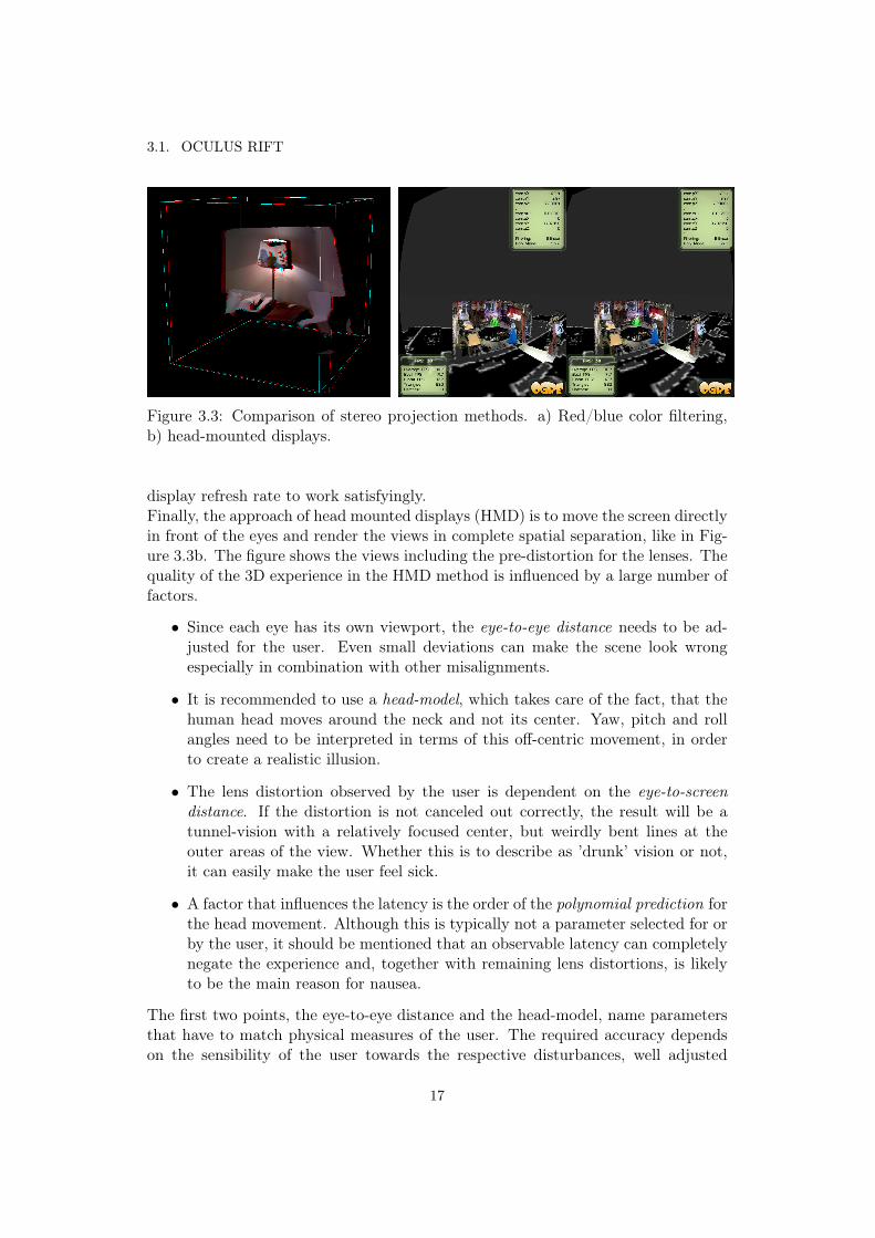
If color or polarization filters are applied, the two views are merged on the samescreen, but are coded differently, see Figure 3.3a. Color filters usually use a redand blue filter to distinguish between the eyes, while the second method relies onorthogonal waveform polarization. The user has to wear goggles with the appropri-ate filters in order to experience the effect. Color filters are extremely cheep, butwill alter the original scene colors as well, which makes them less interesting formany commercial purposes. Polarization filters are today’s standard approach for3D movies in cinema, due to relatively low cost and better color preservation.
Shutter glasses use a different method. Instead of merging and rendering the twoviews in a single frame, i.e., separating the views spatially and ’coding/coloring’them, the views are rendered and shown alternatingly. The shutter glasses have toblock and clear the path to the respective eye synchronously. Besides the synchro-nization between rendering PC and the shutters, this method requires a very high
16
3.1. OCULUS RIFT
Figure 3.3: Comparison of stereo projection methods. a) Red/blue color filtering,b) head-mounted displays.
display refresh rate to work satisfyingly.Finally, the approach of head mounted displays (HMD) is to move the screen directlyin front of the eyes and render the views in complete spatial separation, like in Fig-ure 3.3b. The figure shows the views including the pre-distortion for the lenses. Thequality of the 3D experience in the HMD method is influenced by a large number offactors.
• Since each eye has its own viewport, the eye-to-eye distance needs to be ad-justed for the user. Even small deviations can make the scene look wrongespecially in combination with other misalignments.
• It is recommended to use a head-model, which takes care of the fact, that thehuman head moves around the neck and not its center. Yaw, pitch and rollangles need to be interpreted in terms of this off-centric movement, in orderto create a realistic illusion.
• The lens distortion observed by the user is dependent on the eye-to-screendistance. If the distortion is not canceled out correctly, the result will be atunnel-vision with a relatively focused center, but weirdly bent lines at theouter areas of the view. Whether this is to describe as ’drunk’ vision or not,it can easily make the user feel sick.
• A factor that influences the latency is the order of the polynomial prediction forthe head movement. Although this is typically not a parameter selected for orby the user, it should be mentioned that an observable latency can completelynegate the experience and, together with remaining lens distortions, is likelyto be the main reason for nausea.
The first two points, the eye-to-eye distance and the head-model, name parametersthat have to match physical measures of the user. The required accuracy dependson the sensibility of the user towards the respective disturbances, well adjusted
17

CHAPTER 3. SYSTEM COMPONENTS AND BACKGROUND
parameters usually extend the time that can be spent in the VR before feelingdizzy.In order to cancel out the lens effects, each viewport has to be pre-distorted in a so-called barrel-distortion, which essentially is a radial scaling, where the scaling factoris determined by a 6th order polynomial in r. According to [38], the formulation inpolar coordinates is
(r, φ)→ (f(r)r, φ),with f(r) = k0 + k1r + k2r3 + k3r
6, (3.1)
where the ki parametrize the distortion. An adjustment can be necessary, since theeye-to-screen distance and the eye itself vary for each user.The effect of motion sickness caused by virtual reality is assumed to stem from mis-matches between the visual information shown in the HMD and other perceptions,e.g., the sense of balance in the inner ear. This example in particular is the result oflatency, i.e., delays from the motion-measurement to the end rendering chain. Whilethe sense of balance reports a head movement, the visual input reacts delayed. Oneassumption is that the body interprets these delays as a result of poisoning (e.g.,due to the consumption of bad food), which leads to the feeling of sickness andeventually even the reaction to throw up. The delays are a technical limitation andeven if the computational power and bandwidth increases, delays will always bepresent. The limitation can however be reduced mathematically by predicting thehead-movement into the future to cancel out the delay. For the sensor fusion andangle estimation, a 5th order polynomial-prediction is applied.
3.2 Mobile Robot: Scitos G5The mobile robot is the second important technical component in the project. Asexplained, it is supposed to run in an exploration mode to scout its environmentand provide scene snapshots to fill the VR. The robot is therefore equipped withAsus Xtion kinect-like camera sensors. The heart of the robot is an embedded PCwith an Intel Core 2 Duo Mobile processor. The machine runs the Robot OperatingSystem (ROS) [40], which is a modular operating platform for robotic applicationsand includes a huge variety of packages that handle sensor data, task managementand communication. For the communication a wireless router is set up locally inthe lab, which connects remotely (via wifi) to the robot.
3.3 Robot Operating SystemROS is a large open source tool-set and collection of general purpose libraries tooperate robots. Since the tasks and possible technical equipment of a robot is quiteunpredictable the system aims at being highly adaptable. Thus, ROS is organizedvery modular in packages that can be loaded (even during run-time) and are orga-nized by a central root element, the roscore. Every program is connected as a nodeor nodelet to the core. All communication between nodes, even the information flow
18

3.3. ROBOT OPERATING SYSTEM
from sensor input, over different processing steps, to some output is registered in theroscore in terms of so-called ’topics’ and can be modified by a publisher (providingtopic content), or a subscriber (processing topic content). The system works ’ondemand’, meaning that topics will be advertised all time, but only processed andpublished, if a subscriber exists. It is in the nature of this setup that the nodes workas asynchronous tasks in individual threads and make indeed good use of modernmulticore technology. ROS provides library functions for message synchronizationand buffering as well as many utilities to access important information, e.g., trans-formations between local coordinate systems. Furthermore, many utility functionsallow easy integration of other libraries, e.g., the point-cloud library [41] or OpenCV[42].
$ rostopic list/cam/rgb/cam/rgb/compressed/navigation/motor1/state...
roscore
node1 node2 node3 node4navigation motor
controlcamera visualization
Machine 1 - Robot Machine 2PC
nodelets
imagetransport
network
ROOT
Figure 3.4: Incomplete sketch of ROS elements. All program nodes are registered atthe roscore and may utilize nodelets, running e.g. conversion algorithms to supporttheir task. Network connections are managed by the system automatically.
Another advantage, particularly for this project, is that ROS automatically wrapsnetwork connections. All it requires, is to tell the nodes their own host-name andthe address of the roscore by setting the respective environmental variables and theconnection will automatically be set up, whenever a subscription requires data overthe network.Take for instance the software setup in Figure 3.4, where four nodes are loaded andconnected to the roscore. Out of these nodes, three are started on the robot itself,organizing the sensing, navigation and action (motor control). For the purpose
19

CHAPTER 3. SYSTEM COMPONENTS AND BACKGROUND
of supervision a visualization node is started on a external PC and connects tothe roscore via a wireless link. In order to obtain the camera stream from therobot sensor, the visualization requests the images in a compressed form, whichrequires the sensor-node to fire up the respective compression nodelets. It shall bementioned that for each machine, the configuration can be stated automatically byxml-structured launch files, which makes it a lot easier to manage and test differentconfigurations. Even nodelets can be run from the launch files, yet many extensionslike the image_transport package, provide subscriber types, which support utilitieslike compression automatically.A good place to get started with ROS is the online documentation on [40], whichcontains many tutorials, descriptions and details to the various packages. Sometimeshowever, these tutorials can be a bit of a puzzle, since the pieces of information arespread on different pages or paragraphs. So be prepared to research the packagedescription, together with the tutorial page and eventually the code documentationto fully understand the capability of the system.
3.4 Ogre3D Rendering EngineAlong with the Oculus Rift a software development kit (OculusSDK, [38]) is pro-vided, which takes care of the handling of the sensors and the motion-prediction.However, the rendering process is intentionally not touched by the OculusSDK. Thechoice of a rendering engine is left to the developer and the SDK is designed to beeasily integrated into any environment. For this project the Ogre3D engine was cho-sen, mostly because its community already provides libraries supporting the OculusRift and wrapping the SDK in a very handy way.Ogre3D is an open-source, cross-platform rendering engine. It aims a productiv-ity and the independence from 3D implementations, such as OpenGL of Direct3D,and provides numerous features for scene creation, material and texture manage-ment, animations and special effects. Multiple times the Ogre3D project has beensupported by the ’Google Summer of Code’ and benefits from a strong community.
3.4.1 Main System ComponentsGenerally, rendering engines are wrappers to provide a high level access to thegraphic card acceleration for 3D applications. Ogre addresses this task in a strictlyobject oriented fashion, i.e. providing interfaces, abstract classes and parent classesfor the high-level concepts and leaving the hardware-specific details to the instanti-ated dynamic class types, which are chosen for the executing machine. Take for ex-ample the Ogre::Texture class, which allows you to set up all relevant properties of atexture, but delegates the 3D implementation specific work to Ogre::D3D11Texture,Ogre::D3D9Texture, Ogre::GL3PlusTexture, or Ogre::GL3Texture. The core ele-ments of Ogre are shown in Figure 3.5.Root is by name the initializing instance of the rendering engine. During the ini-tialization the root will detect and set the 3D implementation and prepare the
20

3.4. OGRE3D RENDERING ENGINE
Figure 3.5: Ogre UML overview, taken from the Ogre3D manual.
corresponding hardware buffers and instantiate the window system. Apart from afew parameters, there is not much to set here. From the programmers point ofview, the Resource and Scene Managers are more interesting. The resource systemwill handle every component the scenery will be constructed with. Metaphorically,it defines what a brick looks like, whereas the Scene Manager builds the house.The resource system instantiates each one unique manager for textures, materials,shader programs, etc., and makes it available as static class members according tothe singleton pattern. Once the system is initialized, the singletons can be accessedeasily from anywhere in the program. In contrast to that, the SceneManager is notunique, since there might be different scenes available, e.g., different game levels orareas. This manager holds the information on what actually is displayed. It caninstantiate entities, which are the basic movable objects in Ogre and other morespecialized objects, like lights and cameras.Ogre utilizes a variety of scripts to load plugins, e.g., support for different shaderlanguages, and media (i.e., the resources), which allows to specify and change com-ponents quite comfortably outside the program and more importantly, without thenecessity to recompile after each change.
21

CHAPTER 3. SYSTEM COMPONENTS AND BACKGROUND
3.4.2 Meshes and Textures
In this section the use of meshes and textures is explained in more detail and a fewcommon terms in rendering are defined, before the rendering pipeline is treated inthe next section.Rendering is about forming a 2D picture, displayed on a screen, from the 3D modeldata in the scene and as mentioned, the 3D scene can be subdivided into objectprototypes. Even from simple image processing tool the term pixel is well-known.It is an abbreviation for picture-element and holds the color information for a certainposition in an image.The equivalent for 3D is a vertex (pl. vertices). A vertex holds rendering informationfor a point in the 3D space. This rendering information can be a color, interconnec-tions with other vertices, or coordinates of an image that is used for coloring.The setup of vertices and interconnections is called geometry and images which arelinked to a geometry are called textures. If the setup consists of vertices withoutany interconnection, the rendering result is a point-cloud. In a distant view, a densepoint-cloud can appear as a solid object, but in a close view, the single points willseparate. By telling the engine, how to interconnect the vertices, it is able to fill thespace in between, either by interpolating the specified color values of the neighboringvertices, or by interpolation from the linked texture coordinates and the renderingresults in a surface instead - even from a close view. Although today some enginessupport other geometric primitives, the most common 3D geometry is a triangularmesh and all other polygon structures can be decomposed into a triangular mesh.Basically, the system works with nothing else than a set of 3D points and a strat-egy, what to do with the space in between. In case of color-specification, a nearestneighbor interpolation based on the vertices is used, while in case of the textures,the interpolation works with the nearest texture-element (texel). This way of linkingimage coordinates to vertices is called uv-texturing, where the pair (u, v) indicatesthat 2D image coordinate are used. Figure 3.6 illustrates the coloring. In the upperrow, the three vertices store color values and the engine interpolates smoothly inthe area specified by their connections. In the lower row, the texturing for the robotavatar is shown. The grid is formed by rectangles (which can easily be decomposedinto two triangles each) and every vertex has an according texel in the image in themiddle. The texturing result is shown in the picture at the right.To recap, 3D meshes and textures are important resources for the rendering andform the base for the scene content. In Ogre3D, the resources are organized by amanagement system. In the scene manager, the scene graph is formed and connectsvarious instances of the resources in a hierarchical way. The scene graph is then theinput to the rendering pipeline.
3.4.3 Rendering Pipeline
The rendering pipeline is an abstract concept of how to process the 3D data in thescene in order to display it on screen. Its implementation is the heart of every 3D
22

3.4. OGRE3D RENDERING ENGINE
Figure 3.6: 3D surface representation. Upper row: color interpolation from thecorner-vertices. Lower row: uv-texturing example to form a robot avatar with a 3Dmesh and texture image.
engine. From the bird’s-eye view, the pipeline has three main stages: application,geometry and rasterization. Figure 3.7 illustrates the stages of the pipeline. Theterminology and explanations are a summary of [43], Chapter 2.The application stage is where the programmer has full control over the engine. Ina computer game for example, this stage would contain the game AI, processing ofthe user input and according adaptations of scene content or properties, like detaillevels or textures. A general sub-structure of this step cannot be given, since it isentirely up to the developer to design the application, which could include e.g., multi-threaded tasks for speedup, or simply single-threaded sub-pipelines. The outcomeof the application step specifies whatever has to be displayed and in what way andis passed on to the geometry stage.In the geometry stage, the settings from the application stage are applied to the sceneelements. This includes vertex and fragment operations which are processed in thesub-pipeline: scene transform, lighting, projection, clipping and screen mapping. In
23

CHAPTER 3. SYSTEM COMPONENTS AND BACKGROUND
the first step, the scene elements are transformed from their local coordinates intoworld coordinates and then into the camera coordinates, which already equals theuser’s viewpoint. The transformation is calculated along the scene graph, from theobjects to the root and then to the camera nodes. Within this view, lighting andshadow effects are calculated, usually based on the vertex normals of an object.The projection step maps the camera view into a unit-cube according to the chosenprojection type, i.e. parallel or perspective projection. In the normalized space,the clipping step discards everything outside of the user’s view. If objects at thesides are only partially inside the view, this step replaces the unseen vertices withcharacteristic vertices at the border. In the last step of the geometry stage, the unit-cube is mapped into the screen coordinates, e.g., to fit the screen size (in full-screenmode) or the window size.Finally, the rasterization stage is generating the 2D image, which is displayed on thescreen, i.e., finding the correct color for each pixel in the screen raster. In additionto the calculated object colors, lighting and shading effects, this step performs thelook-up of texture elements and eventually interpolates missing values. Based ona Z-buffer (Depth-buffer) algorithm, like for instance [44], the rasterizer as wellconsiders occlusion of scene elements. The screen image is double-buffered to hidethe manipulations from the user and perform them in the background buffer.Geometry and rasterizer stage make both use of the accelerated processing on theGPU. In contrast to the CPU, which has a low number of general purpose processingcores, the GPU has a huge number of very specialized cores. Transformations,projections and clipping tests are per-vertex operations, while texture look-ups andinterpolation are per-fragment operations, which can usually be parallelized withoutfurther constraints and are therefore predestined to make use of this acceleration.
3.4.4 Geometry, Vertex and Fragment Shaders
It has been mentioned that Ogre utilizes a number of scripts to outsource graphicaleffects from the application. While some of these scripts (i.e., material scripts andcompositors) are engine specific, the class of geometry scripts, vertex shaders andfragment shaders are a more general matter.Shader scripts contain a collection of functions that operate on geometry, vertex,or fragment data respectively and can be compiled during start-up and executedon the GPU. They are commonly applied to generate post-rendering effects, i.e.’last-minute’ application of additional highlighting/shading textures, vertex bendingeffects (object deformations) or transparency effects. Modern shaders allow datacrossovers, in the sense that a fragment shader can make use of vertex data, forinstance. The bridge to the application are the textures and material parameters,which can be set from within the 3D engine. OpenGL, Direct3D and global vendorslike nvidia have created several languages to define shader programs. In this project,nvidias shader language ’cg’ is used to speed up the reconstruction of 3D contentfrom image data. The code is written in a C like fashion and with [45] a good onlineresource exists to step into the details.
24

3.5. OBJECT ORIENTED INPUT SYSTEM
Application
Geometry
Model & ViewTransform
Lighting &Shading
Projection ClippingScreen
Mapping
Rasterizer
<Developer>
Figure 3.7: General rendering pipeline. Inspired from [43].
3.5 Object Oriented Input SystemThe Object Oriented Input System (OIS) is an open-source cross-platform libraryto access mouse, keyboard, joystick and gamepad devices for gaming purposes. Itprovides an easy to use interface, featuring event-callbacks and status-requests andwraps the driver handling for the software developer. Most popular input devicesfrom all commonly known manufacturers are supported. The role of OIS will be aminor one, though, since the gamepad can, for the course of this project, be moreefficiently accessed via ROS. In fact, to reuse an existing teleoperation node for therobot, the ROS message system has to be used, leaving keyboard and mouse inputfor the OIS library.
25


Chapter 4
Implementation
This projects purpose is to create a platform for teleassistance and visualization,which makes the implementation part a fundamental part. This chapter explainsthe methods and tricks to integrate the different systems and libraries into oneapplication. It answers the question how the empty 3D space is filled with content,what techniques ensure a feasible data transmission and save the frame rate fromdropping. Furthermore, the user-interface will be specified in detail, by defining anddiscussing the possible actions. The chapter is concluded by a summarizing systemoverview.
4.1 The Fundament
... is the Ogre3D tutorial application. It is published on the website [46] and containsa basic structure to run the engine and already handles keyboard and mouse inputs.The structure separates the scene creation from the rest of the application, aimingat an easy setup for large static environments. Although the environment is ratherdynamic in this application, the structure was preserved and the scene creation isused for the initialization of the graphic objects instead. Every entry point to theapplication layer of the rendering engine is given in the form of callbacks and hence,for every event the application needs to react on, the base application implements theaccording listener pattern, e.g., a frame listener to get access to the start, the eventqueue and the end of each frame. The input structures from OIS and ROS fit quitewell into this setup, since they both work based on callbacks, or at least have theoption to do so. A part that has to be adapted is the handling of the player motion,for which the tutorial application applies a utility class. The stereo rendering forthe Oculus Rift however requires a certain setup of camera and scene nodes in orderto model the user’s head and the according distances described previously.For the handling of the Oculus Rift, a free package from the Ogre3D communitymember Kojack was used. It takes care of the necessary scene node and camerasetups and includes material, composer and shader scripts for the lens distortion andcolor adaptation. The interface is a single oculus object which has to be instantiated
27

CHAPTER 4. IMPLEMENTATION
before the rendering is started. It initializes and registers the motion sensors, setsup the camera nodes for left and right eye and connects them to viewports on theleft and right half on the application window, accordingly. In the frame events ofthe rendering loop, the view can then be updated, simply by calling the update()method of this instance. To comfortably organize the movement of the player body(independent from the head), the package was slightly modified to fit to a utilityclass, which was programmed to wrap the handling of the user input and convert itinto player movements. Since the Oculus Rift blocks the user’s vision, a user inputrelying on keyboard and mouse seemed inappropriate and the options were thereforechanged to a gamepad as main input device.With these elements in place, the application is able to render any scene in stereoand take various user inputs from keyboard, mouse, gamepad and the Oculus Riftinto account.
4.2 Building the EnvironmentThe central question now becomes how to fill this empty space with the 3D datathe robot collects. At every time instance, the user will see a low-fps (2 fps) videostream from the camera sensor and further options are given to save 3D informationfrom this video stream. The kinect-like camera publishes a rgb image and depthimage and the low frame rate is a compromise due to the bandwidth as discussed inthe following subsection 4.2.1. Afterwards, the process of reconstructing a 3D viewfrom the two images is explained in subsection 4.2.2. Furthermore, the messagehandling and synchronization is discussed and the user interface is introduced.
4.2.1 Bandwidth considerations
On the robot itself the information is mostly used in the form of point clouds,where each point consists of the 3D coordinates, color information (rgbα) and otherassociated data, e.g., a label to denote a cluster this point belongs to. Becausethe point-cloud data is comprehensive and uncompressed, it yields some problems.Firstly, the data has to be transmitted from the robot to the rendering PC and sec-ondly, the data has to be processed and inserted into the scenery without decreasingthe frame rate too much. The Asus Xtion camera on the robot provides a resolutionof 640 × 480px resulting in 307200 points for each image. The required minimalbandwidth Bpc for the transmission of an unlabeled point-cloud could, for instance,be
Bpc = (640 · 480points · 4bytes/float · 4floats+ sh) · fs ≈ 49.15MB/s (4.1)
if the sampling frequency fs is set to 10Hz and all values are coded as float32,i.e., one float for x, y and z and one extra to code color as rgbα and assumingadditional header information in the size of sh = 16bytes. Note that such bandwidthvalues are far too high for the available wireless connection in this project (wifi,
28

4.2. BUILDING THE ENVIRONMENT
rated at 54Mbit/s), as well as the memory consumption and processing load is veryexpensive for rendering purposes. During the development of the system, a versionwith a point-cloud stream was tested on a local machine (i.e., without the wirelessconnection) and resulted in a frame rate between 0.5 and 2 fps. One way to decreasethe data volume would be to compromise on the data rate, or the number of points,but still sub-sampling the point-clouds does not tackle the real problem.The point-cloud contains all information in high-detail, but lacks compression. Forthe camera images, which were used to generate the point-cloud in the first place,efficient image compression exists in the form of the PNG and JPEG formats. Withthe PNG format a loss-less compression, suitable for the depth images, is possible,while the rgb images can even be compressed with the slightly lossy JPEG format.ROS, which is used for the sensor management and the image acquisition, providesa tool to measure the bandwidth of a topic. Table 4.1 compares the measurementsfor the different possible topics.
values in MB/s rgb depth bothuncompressed 27.9 37.2 65.1compressed 1.49 3.53 5.02point-cloud 121.5
Table 4.1: Comparison of data representations for transmission (Peak values at afrequency of 20 pictures per seconds). The point-cloud was published at 10− 11Hz,but uses a different format as in the derivation example above.
Compressing the images yields an acceptable bandwidth and makes the wirelesstransmission feasible. On the applications side, the remaining task is to processthe compressed images into something that can be rendered in 3D. The obviouschoice, of generating a point-cloud on the rendering PC as well, has been tested,but was discarded for performance reasons: Ogre3D allows the creation of so-calledManualObjects, which are containers for user-defined geometry that can even bechanged during runtime. However, each manipulation of an object (creation orupdate) requires a recompilation of the geometry, leading to a significant pause inthe rendering loop and destroying the fluency of the application. Considering the factthat the point-cloud is constructed from the rgb and depth image, given the cameraposition and orientation, it can be stated that the images themselves must containall information needed for the 3D reconstruction. Thus, the method of choice is torebuild the view directly, instead of converting the data into a point-cloud. Thesereconstructed views will in the following be called (3D) snapshots.
4.2.2 Snapshot Reconstruction from Textures and Shaders
In subsection 3.4.4, the shaders were mentioned as mini-programs to operate onvertex and fragment data and to post-process rendering objects, e.g., by applyingtextures. The method described in the following makes use of the fact that the
29

CHAPTER 4. IMPLEMENTATION
geometry of the images, i.e., the number of vertices and their interconnection as atriangular mesh, is the same for all images. Rather than redefining and recompilingthe whole geometry for every incoming snapshot, a single standard geometry isdefined, compiled to a mesh and the snapshot each time instantiated as a copyof the default mesh (saving the time for the compilation). Figure 4.1 shows thegeometry of the snapshots.
xyz
Figure 4.1: Left: standard geometry for the snapshot objects. Right: back-projection from the standard geometry, considering pixel neighborhood for color-interpolation and the taking z-axis as focal length.
Each vertex is connected to 6 out of 8 neighbors in a dense triangular mesh. Inthe standard object and its local coordinate system, the vertices just need to have ahorizontal and vertical coordinate, the depth can be set to a default value (0.0f) andwill be replaced from the depth image by the vertex shader. Note that in Ogre thedefault depth value might still be used for collision checks and clipping, which canmake it necessary to adjust the value. In addition to that, the texture coordinatesfor the rgb image will be set along with the geometry.A depth image contains the Z coordinate of a 3D point, which is the distance betweenthe projection origin of the camera and the point along the camera plane normal.In order to perform the back-projection, the following formulas hold
X = xf · d
Y = yf · d
Z = d (4.2)
Where d is the depth value, (x, y) are the image coordinates as shown in Figure 4.2and (X,Y, Z) are the 3D coordinates. The fractions x/f and y/f are the same ineach image and since the coordinates have to be rearranged anyway, the geometrypositions can be used to store the fractions directly, instead of (x, y), which will savesome computations. Finally, the rgb and depth images are loaded as textures and
30

4.2. BUILDING THE ENVIRONMENT
registered in the material of their respective mesh-instance in order to have themaccessible for the post-processing by a vertex and fragment shader.
Vertex Shader Fragment Shader
Figure 4.2: Back-projection of a snapshot. The depth and rgb values are readfrom textures and applied in shader programs. A vertex shader takes care of thecorrect placement, while the fragment shader sets the final color value and eventuallydiscards pixels, if they are in an area of a jump in the depth.
As shown in Figure 4.2, first, the vertex shader registers the specified depth tex-ture and performs the transformation from Equation 4.2 in the local coordinatesystem and afterwards transforms the snapshot into the world coordinate frame.The transformation into world coordinates is always accessible and calculated inthe 3D engine by traversing the scene graph and applying all transformations fromthe current scene node to the root. As a result the (basically) 2D geometry is nowconverted to a 3D geometry and the mesh makes it possible to construct a surface.Second, the fragment shader takes care of the coloring. It registers both depth andrgb texture. The depth texture is needed to estimate, if the pixel is lying in a flatsurface, or in an area where the depth value makes a sudden jump. In the lattercase, the pixel is discarded and not displayed, since a sudden jump usually means atransition from fore to background, which should not be connected by color interpo-lation. If instead the surface is smooth, the fragment shader looks up the accordingvalue from the rgb texture and outputs it. In the implemented version, the estimateis done by looking up the depth values in the neighborhood of the current vertex.An alternative would be to use a third texture as a mask, i.e. a Boolean map sayingwhether to display the pixel or not, with a precomputed highlighting of the edges,e.g., from an image gradient. The advantage would be to have one additional texturelook-up during rendering instead of six (due to the 6 out of 8 neighborhood), on theprice of a longer image processing step and an additional texture registration.
31
CHAPTER 4. IMPLEMENTATION
4.2.3 Connection to ROS
From the past sections it is known which image types can be transmitted and how touse them in order to reconstruct the snapshot efficiently. Still, even the compressedimages have to be processed and the snapshot orientation and translation has to beobtained from the robot, too. This section focuses on the missing aspects neededto complete the connection from the ROS system on the robot to the renderingapplication. The compression of the images is taken as given. As explained in theexample in section 3.3, the image_transport package takes care of all conversions.
Multithreaded Message Handling
Sending compressed images to the application is not enough. The images are cap-tured and transmitted by the ROS in system-specific messages with according time-stamps and other ROS header information. In the visualization, the messages haveto be converted into a data format the rendering engine can handle and a synchro-nization between the rgb and depth channel is desirable, to ensure the best possiblealignment between the images for a good 3D reconstruction.One of the main criteria for a immersive VR experience is a smooth rendering. Thisimplies that the effect of the image processing steps, i.e., the conversion from asensor_msgs::CompressedImage to an Ogre::Image, which can be loaded as tex-ture, must be minimized. It has already been mentioned that ROS supports multi-threading very well, due to its modularity, but even for a single node, ROS providesthe option to launch the callback cycles in separate threads. Thus, the easiest wayto avoid frame rate drops is to perform the message handling as an asynchronousparallel task. For the conversion, the binary data blob of the ROS messages is loadedinto an Ogre::DataStream object, which can then again be decoded into an image.Unfortunately, the message data block contains some overhead in addition to thePNG or JPEG image. Hence, streaming the data directly into the engine will notwork. Instead, the stream is searched for the flags which denote the start of a PNGor JPEG image and afterwards cropped to the image content, by cutting off allprevious bytes. Once all images are converted and the according camera transfor-mations have been fetched, the callback informs the engine that there is an updateand the engine will handle the update at the next frame event. To avoid crashes dueto data access from multiple threads, the message handling has to be paused untilthe engine has placed the update, which can - on low frame rates - cause messagelosses.Although the processing step is an asynchronous task, the rgb and depth mes-sages have to be synchronized. This is again supported by ROS in the form ofmessage_filters and TimeSynchronizers with different policies for synchroniza-tion. Figure 4.3 illustrates the process of synchronization and conversion.Basically, the message_filters are buffers, subscribing to a topic and collecting anumber of messages sorted after a certain criterion. Together with the TimeSynchronizerthese buffers are used to find pairs of messages, based on their time stamp and can
32

4.2. BUILDING THE ENVIRONMENT
APPROXIMATE_TIME
matching policy
callback( rgb_image, depth_image ){ //process rgb_image //process depth_image
//lookupTransform}
Message Filter TimeSynchronizer Callback
Figure 4.3: Message filtering and approximate time synchronization by ROS. Thefilter sorts the messages according to their time stamp and the synchronizer pairsup two approximately matching images into one callback.
be bound to a single callback to do the processing. The selected synchronizationpolicy EXACT_TIME or APPROXIMATE_TIME decides how strict the pairing is done. Forthis project, it turns out that the exact policy does usually not provide rgb-depthpairs at all and hence, the approximate time policy is applied.A synchronized image pair allows a good 3D reconstruction, but two images alonemerely bear the information of the local coordinates. In order to place the snapshotin the world coordinates, the camera translation and orientation at the time instantthe pictures were taken have to be known, too.
Listening to Transforms
The mechanism to access information on transforms is different from the usual mes-sage handling. On a robot, there are many potentially interesting local coordinatesystems required by various elements of the overall system. In ROS, these local co-ordinate systems are being referred to as coordinate frames. In order to keep trackof the various frames, ROS stores all transformations between connected coordinatesystems in a transformation-tree (tf-tree), with the world coordinates as root ele-ment. To obtain the transformation between two different frames, the connection ofthe frames in the tree are searched and the according transformation matrices areapplied along the path. Delays from processing or communication make it necessaryto track the time dimension as well and store the past of the transforms up to acertain duration. Keeping the tf-tree up to date, creates a constant message traffic,of course, but for convenience, the handling of the individual updates are hiddenfrom the developer within the tf::tfListener class. With a simple function call,the transform between all registered coordinate frames can be requested within thestored time frame. If the time instant requested is not present exactly, the returned
33

CHAPTER 4. IMPLEMENTATION
result will be an interpolation between the two closest states.With reference to the project, this means the callback which handles the synchro-nized image messages can simply fetch the appropriate transform from the tf-tree.For an optimal re-projection the transform has to match the time stamp of thedepth image. Another problem in connection with the transforms, are the differingcoordinate systems in ROS and Ogre3D.
Coordinate Systems
Ogre3D applies the xyz coordinate system as right, up and backward direction,which is very commonly used in 3D engines. ROS actually has specifications fortwo sets of base vectors. The commonly used set applies xyz as forward, left andup direction. For cameras and other optical sensors, a second frame is generated,which codes xyz as right, down and forward. Figure 4.4 shows all three variants incomparison.
(a) Ogre coordinate axes. (b) ROS coordinate axesfor geometry.
xyz
(c) ROS coordinate axes foroptical frames.
Figure 4.4: Comparing the coordinate systems in Ogre3D and ROS. x is colored asred, y is green and z is blue. Note that all coordinate systems are right-handed.
There are different methods to transform the coordinate systems into each other.The way chosen for the application is to fetch the transformation from the opticalframe to the world coordinates and rotate it to the Ogre3D orientation. This adap-tion is done by decomposing the rotation into yaw, pitch and roll and resorting themto the target coordinate system.
4.3 Taking ActionIn this section, the user interface is described in detail, naming the various inputoptions and discussing the possible actions in the virtual environment and for theteleoperation, via a gamepad. Since the Oculus Rift blocks the user’s vision itis important to use an intuitive set of commands, which can be operated from asingle device. The choice for the gamepad was taken, because it is a comparatively
34

4.3. TAKING ACTION
ergonomic device with few input keys and joysticks, which can easily be operatedwithout looking. In modern computer games, gamepads are commonly applied totake a vast amount of input commands via the buttons and various combinations ofbuttons, triggers and joystick movements - a complexity that exceeds the needs inthis project by far.Within the virtual environment the user is able to move around freely, in order toexplore the world from arbitrary angles and viewpoints. At any time instance therobot position is updated and visualized by an avatar. By holding one button pressedthe user can switch modes to robot-control and the gamepad input is redirected tosteer around the robot, while the last viewpoint of the user is preserved. Theadvantage of this setup is the ability to choose the best viewpoint for the controlsituation, e.g. a side-view to approach an obstacle, while the draw back is that forenduring control situations the viewpoint has to be adapted and hence, the user hasto switch between robot- and player-control mode.Switching the control modes is realized via the ROS system again, in a standalonenode. The gamepad is handled as an input sensor and checked for the mode button.If pressed, the joystick state message is republished on a topic for a previouslyimplemented control node for the robot, otherwise, it is routed to the topic for thevisualization tool (see Figure 4.6). Figure 4.5 shows all input options granted to theuser.
map visibility snapshot
room panorama
panorama visibility
snapshot visibility
player: up/down and left/rightrobot: camera angles
forward/backwardturn left/right
hold: robot control moderelease: player mode
first person /free viewpoint
oculus sensor reset
Figure 4.5: User interface for player navigation and robot control.
In "robot control mode" the signals are routed to the Scitos G5 and the user canremotely steer the robot in forward/backward direction or turn it left/right (unicycle
35

CHAPTER 4. IMPLEMENTATION
machine). For the "player mode" there are much more options:
• moving the player is done with the joysticks and allows forward/backward,left/right, up/down and turn left/right movements. Looking up/down orrolling the head is only possible from the Oculus Rift input. The idea isthat the virtual player - controlled from the gamepad - represents the user’sbody, which although the user is allowed to fly around, should not be pitchedor rolled.
• handling snapshots with the gamepad buttons, the user can
– take snapshots
– change their visibility (on/off)
– trigger an automatic panorama (360◦)
– flip the visibility of the panorama
• use utilities such as the 2D map of the surrounding, switching between first-person and free-viewpoint, or resetting the Oculus Rift orientation.
4.4 OverviewThis final section summarizes the design from the different perspectives of ROSand Ogre3D. The overall system in Figure 4.6 displays the same components as inFigure 1.2, but adds the integrated software components and details of the commu-nication channels. It is shown that the application integrates the Ogre3D engine(handling the rendering for the Oculus display), the OculusSDK (handling the mo-tion sensors) and ROS (routing the joystick signal and handling the sensor data fromthe robot) to a 3D visualization tool. Furthermore, the graphic shows the multiplechannels from the robot to the application.There are in total four channels for image transmission: rgb and depth channel forthe user-triggered snapshots and rgb and depth channel for the automatic roompanorama. Finally, there is a channel to transmit the robots transformation, i.e.,the position and orientation of all movable robot parts.
In the Ogre3D engine it is worth looking at the scene graph, which is built up duringruntime and collects all elements that are rendered. Figure 4.7 shows the completescene graph.As mentioned in section 4.3, the virtual player, PlayerBody, represents the body ofthe user and is restricted in the possible orientations. The head movement, trackedfrom the Oculus Rift, is then super-positioned in the CameraNode. The RobotNodeholds the robot avatar, a pre-loaded and textured mesh, and is updated each framein its orientation and translation. While the child nodes in SnapshotLibrary andRoomSweep store the recorded textures for static rendering, the VideoStream nodestores textures optimized for dynamic access in order to be updated at 2Hz. For the
36

4.4. OVERVIEW
U S E R
output
input
OGRE3D
ROS
Vizualization
Message Handling
OculusSDK
Wifi
routing
Oculus Rift
Gamepad
R O B O T
Figure 4.6: System overview displaying the application components (Ogre3D, Ocu-lusSDK and ROS), the parts they handle (rendering, motion sensing, image andcontrol message handling) and the channels used in the system.
RootSceneNode
CameraNode(Head)
LeftEye RightEye
RobotNode SnapshotLibrary RoomSweep
Snapshot_0Snapshot_1Snapshot_2...Snapshot_N
Snapshot_0Snapshot_1...Snapshot_M
PlayerBody VideoStream
Figure 4.7: Scene graph in Ogre3D. Oculus Rift orientation and player movementare decoupled even in the setup of the scene nodes holding the PlayerBody and thecameras for left and right-eye. There are extra nodes for the robot and the videostream, as well as two nodes collecting the 3D Snapshots and the room panorama(s).
library nodes, a wrapper-class takes care of the memory management and preallo-cates memory chunks in order to keep the influence on the rendering framerate to aminimum.Flipping the visibility of the snapshots (one of the player actions) means flipping thevisibility of the library node and iteratively forwarding the setting to all children. Iffurther snapshots are taken, they are attached to the library as visible, which as aresult means that two sets of snapshots/panoramas can be recorded.
Finally, an overview about the application flow is given in Figure 4.8. On startup,the Ogre3D Engine has to be initialized first, setting up the rendering and resource
37

CHAPTER 4. IMPLEMENTATION
initOGRE
initOculus
initROS
deleteROS
deleteOculus
deleteOGRE
rendering asyncSpinner
joystick
images
transformsshutdown?
frameStart
...
frameEnd
RenderingThread
ROS MessageThread
ROS callbacks
Figure 4.8: Application flow. After initializing the different systems, the render-ing loop is started and recieves (most) updates from the asynchronously runningROS thread. All updates are introduced in the beginning of a frame event. Ontermination, the ’shutdown’ command is broadcasted through the system and allcomponents are cleaned up.
system, and loading plugins and needed graphical resources. The Oculus wrappercan be initialized afterwards, to configure the camera and screen setup for the stereorendering. The final step before entering the rendering loop, is to initialize the ROS,which means to configure all topic subscriptions and to start an asynchronous threadfor message handling.During the runtime, the updates from the messages are processed (prepared asrendering update) in the separate thread as good as possible. Once an updateis ready, it is inserted at the beginning of the next frame. There are two things tonote about the ROS messages. Firstly, the depicted functions - with the exception of"transform" - represent callbacks, which is, why there are now connections indicatinga ’flow’. Secondly, the transformations, as pointed out earlier, are handled hiddenfrom the programmer in a Listener object and although it updates asynchronouslyas well, it is actually not a callback.Stopping the program works in reverse order of the initialization. First the separate
38

4.4. OVERVIEW
ROS thread is stopped and the ROS compenents are cleaned up. After that, theOculus wrapper and finally the 3D engine may follow.With these overviews the implementation is concluded and the reader has hopefullygained some understanding of the concepts behind the application. The next chap-ter introduces the experiment and the user study which were used to evaluate thesystem.
39


Chapter 5
Experimental evaluation
The question addressed in this chapter is "How do I know if and how good itworks?". The emphasis in the introduction has pointed much in the direction ofhuman-machine interaction, which will hence be reflected in the user study thatforms the experiment. The goal is to get a proof-of-concept that the combination ofthe Oculus Rift with a mobile robot provides a useful teleoperation platform. In thelinked literature some examples are included for this type of evaluation in [15, 11],in order to make the results more comparable.The papers have in common that the users had to solve one or multiple tasks in aparkour. In [15] the research focus was on the comparison between different view-options, i.e., first-person, third-person and free-viewpoint, with the result that thefree-viewpoints allow the most accurate steering in terms of approaching an obstacle.The measures taken in [15] were the time for the task execution and the distance tothe obstacle, which had to be approached as close as possible, but without collision.The strength in the method is that it provides both objective measures and sub-jective feedback to evaluate the system. In [11] the tasks included teleinteractionwith objects in the environment and the number of unintended object collisions wasrecorded in addition to the time until task completion. Since the type of robot hasa different task and equipment from the Scitos G5, it will be hard to compare theresults to this study. In addition to these two user studies, the paper [47] lists com-mon metrics for human-robot interaction and discusses their application and relatedfactors. It identifies different classes of measures in an attempt to group the metricsin these categories, e.g., the time-until-completion is named as an efficiency measurefor navigation tasks and distances relate to spatial perception (for teleoperators).With these sources in mind, the experiment is designed to take similar measures intoaccount. The idea of a parkour1 with different navigation and exploration tasks iseasily feasible. In the evaluation, the focus is on the user experience and the situa-tion awareness due to the VR. Apart from the measurement, a set of questions willallow the user to grade his experience subjectively on a scale from one to five. Beforegoing into the details of the evaluation process the experimental setup is introduced.
1In this context, a testing route in the laboratory with tasks and obstacles.
41

CHAPTER 5. EXPERIMENTAL EVALUATION
5.1 Experimental setup
Following the description in this section, it should be possible to get an impressionon the environment the user has to explore and the difficulty of the task. Figure 5.1shows a map of the experiment. Along with the necessary equipment for the controland visualization, the user is placed in a room on the corridor. The robot itself willbe placed in the corridor, right in front of the room, so that the initial position ismore or less unknown. The user is then told to steer the robot back into the room,where two other tasks await. The location of the room will be known at least in somesimple linguistic form, e.g., "Down the corridor, on the right side". In the room, theuser will then approach the whiteboard in order to read out a text that is written onit (during task 1, while the user cannot see it). Indeed, the text formulates the thirdand final task, which is to find a marked area on the ground and steer the robot intothis ’parking position’. More precisely, the user is asked to park the robot on top ofa shape, which is taped on the ground, and in the direction which is denoted by anarrow inside the shape. An example formulation of the third task could be "Findthe black shape and park the robot."
initial robotposition
parkingpositions
whiteboardop
era
tor
corridor
room
narrowdoor
task1
task2
task3
obstacles
robot path
Figure 5.1: Experimental setup.
42

5.2. USER STUDY
This aims to test the following qualities:
• Task1: Navigating to the room will give a hint on how comfortable the useris with the control of the robot. How well is the orientation in the environ-ment and how easy can the robot be lead to a basically known location? Anappropriate measure is the time between start and arrival in the room.
• Task2: Reading out a text from the whiteboard motivates the user to explorethe room, experiment with camera angles and take snapshots. The evaluationwill be either yes or no, stating if the user succeeded in finding and readingout the text or not.
• Task3: The final task of steering the robot to a denoted parking position ofunknown exact location challenges the user to explore the environment to ahigher extent. The final measure will be the distance from denoted shape to therobot, if the shape is not covered completely by the robot. Additionally, theangle between the denoted position and the final robot orientation is recorded.Both measures are taken, when the user is satisfied with the position, whichmeans, it is the user ending the experiment.
From these tests a general intuition about the quality can be obtained and theprovided measures will allow a basic comparability to the named sources. Notethat especially the time intervals will not be comparable, because the length andspeed of the robots in the references are unknown. Still, variance or range can beused to judge, if the difficulty is comparable for all participants, or if the operationtime depends on the user’s experience in robotics. It should be mentioned that theapproach to solve the tasks was up to the user. For instance, in order to solve taskone, some did well with just the low-fps video stream, others relied on snapshots ofthe door.
5.2 User Study
Besides the performance measures, the user is given the opportunity to provide feed-back in a questionnaire. Five questions allow grading the experience from (1) to (5),a sixth question on nausea has several options and two open questions allow for anykind of free feedback. Furthermore, the user is asked to comment on his backgroundexperience with technology and robotics in particular. The questionnaire is shownin the appendix in Figure A.1 and it is recommended to take a look in order tointerpret the evaluation results.The user study was conducted under one week and in total N = 12 participantstested the system, who were invited in small groups of 2-3 persons. Four peoplewere researchers at the CAS/CVAP institute, four people were students with tech-nical majors and four participants had a non-technical background.
43

CHAPTER 5. EXPERIMENTAL EVALUATION
5.3 Results
In the following, the results are listed and discussed. First, the measures fromthe experiment are considered, followed by the subjective feedback. The section isconcluded by a discussion of the most important comments from the free feedbackand reflecting on the results.
5.3.1 Measures
As explained in the experimental setup, the measures taken were the time to com-plete the first task, the yes/no answer, if the participants were able to read outthe text on the whiteboard or not and distance plus angle for the denoted parkingposition. Table 5.1 shows the mean value and the range of the measures.
measure mean rangeM1 [min] 7:08 [2:15, 14:00]M2 [y/n] 1.0 –M3 [cm] 7.6 [3, 20]M4 [deg] 13.6 [0, 60]
Table 5.1: Measured results of the user study. M1: time to finish task 1. M2: readingfrom the whiteboard (yes = 1, no = 0). M3: distance from the outer part of theshape to the robot. M4: angle between denoted and achieved parking orientation.
It usually took the participants 7:08 min to steer the robot back into the room. Themajor difficulty was to get the robot through the narrow door, with roughly 5-10 cmat each side at the base of the robot. One participant had problems finding the door,but managed to locate it after changing the approach from video-based navigationto snapshots. The fastest time of 2:15 min was achieved by a research engineer,who had experience in controlling the robot from before and solved the task withthe video-stream, exclusively. Typically, the group without robot experience wouldsteer the robot very carefully (with some fear of damaging the system) resulting ina longer time for Task1. The exception was one participant, who asked, if the robotwould take damage if driven against a wall. After clarification of the question (abumper on the robot base would most likely prevent such damage), the participantacted with more confidence and solved the task faster than average and withoutcollisions. It can be concluded that the time of operation is indeed depended onthe user’s previous experiences with robots, but as well on the attitude of the user,in the sense that a self-confident, unexperienced user can be expected to reach asimilar time-to-completion compared to a cautious user with training.Every participant managed to read out the whiteboard text. Only two participantsneeded to re-position the robot and had to flip the visibility in order to record a newsnapshot of the board, before the task was solved.No one managed to park the robot exactly on top of the shapes, covering them
44

5.3. RESULTS
completely. This turned out to be a flaw in the experiment. The robot avatar inthe virtual environment is slightly bigger at the base and hence, the shape appearedto be hidden in the VR, while it was still partially visible in the real world. Mostpeople did quite well, though, with an average of 7.6 cm of visible shape.Finally, the angle between the denoted and the achieved parking orientation was13.6◦. This average is slightly biased by one large outlier of 60◦, where the partic-ipant simply ignored the denoted arrow. All other values are in the range [0◦, 15◦],with an average of 9◦. Both measures show that dispite the flaw with the avatarsize an accurate teleoperation is possible with the system.
5.3.2 Subjective Feedback IThe questions the users could grade on the scale from (1) to (5) were:
1. "How real did the virtual environment feel?", where (1) states very artificialand (5) states absolutely real.
2. "Seeing the scene in 3D helped my orientation!", where (1) expresses disagree-ment and (5) full agreement to the statement.
3. "I had a good sense of what happened in the real world!", with the same scaleas above.
4. "Moving in the virtual world was:" (1): difficult, up to (5): easy.
5. "Controlling the robot was:" (1): difficult, up to (5): easy.
The evaluation is illustrated in Figure 5.2 by the histograms of the participants’answers.For all participants, there was no doubt that the virtual world was an artificial one.Still, the majority graded the experience as convincing in question Q1. The lowergradings could be a result from the observation of sensor noise, which makes surfacesappear wrinkled instead of smooth, or the lack of scene elements, if no 3D snapshotswere taken.In question Q2, the majority agreed strongly that the 3D perception of the VRthrough the Oculus Rift helped to navigate in the VR and to operate the robot. Someparticipants explicitly mentioned the benefit from the perception of the distance toobstacles, like chairs or tables, or the option to look from different angles.Q3 was answered in the higher part of the scale, but quite mixed. One fact discussedwith the subjects was that the video-stream is in some cases too slow to capturepeople passing by. Persons appear suddenly, without warning in front of the robotand even with a slight delay due to network delays. While for some participantsthis was tolerable, others felt insecure about when to operate the robot and whento wait.Q4 and Q5 have been evaluated quite similar to each other. Since both aim atthe human-machine aspect of the project the result is below the expectation. Most
45

CHAPTER 5. EXPERIMENTAL EVALUATION
participants were overwhelmed by the amount of available functions and used onlyfew of them during the experiment. One assumption is that less options might haveresulted in easier handling for the participants, since the level of complexity alreadyrequires long explanation and some practicing in advance.
1 2 3 4 50
2
4
6
8
1 2 3 4 50
2
4
6
8
1 2 3 4 50
2
4
6
1 2 3 4 50
2
4
6
1 2 3 4 50
2
4
6
8
Q1
Q2
Q3
Q4
Q5
Figure 5.2: Subjective evaluation of the participants. Histograms showing the votesfor the questions Q1 to Q5 of the questionnaire.
46

5.3. RESULTS
The question Q6 of the feedback (not in the figure) was about the occurrence ofnausea, "I had a feeling of motion sickness/nausea:", with the options to answer’never’ , ’after some time’ or ’the whole time’. Out of the 12 participants only onereported to have felt a slight motion sickness the whole time. Four people reportedto have felt motion sickness after a while and 7 participants reported no problemswith motion sickness.
5.3.3 Subjective Feedback II
Further subjective feedback was collected in the form of comments on the ques-tions "What was good?" (⊕), "What should be changed/improved?" () and anyfree commentary (�) on the questionnaire. In the following, the given answers arelisted as keywords, based on the number of participants who named similar fea-tures/problems, starting with the frequently named ones.
⊕ 3D snapshots, easy control, free-viewpoint, first-person, room sweep, numberof functions
robot control, lack of camera-angle visualization, jagged video stream, playercontrol, easier snapshot access, instructions too fast
� couple the human-head motion to the camera-angle
Some of these namings sound contradicting, e.g., the positive naming of "easy con-trol" clearly contradicts the recommendation to improve the aspect of "robot con-trol". The interpretation of the subjective feedback is subjective by nature, too.Still, there are several aspects that were pointed out in the commentary and indialogue with the participants that should be part of the discussion.
5.3.4 Discussion
Reviewing the experimental results, a very positive observation is that all partic-ipants managed to operate the robot through all tasks successfully and withoutmajor difficulties. Even inexperienced participants with no prior experience in con-trol, robotics, or gaming were able to handle the system after less than ten minutesof explanation/training and handled the jump into the cold water well. Looking atthe measures M1-M4 together with the subjective feedback on the questions Q1-Q3confirms that the concept of robot teleoperation (or teleassistance) with the helpof immersive 3D virtual environments provides a capable interface with potentiallyhigh precision, good orientation and situation awareness of the operator. However,the system is in a prototype state. The users gave positive feedback about theavailable options and concepts for the human-robot interaction, while the criticismrelates to details of the current implementation, of which some are easily corrected.For instance, one of the most frequent confusions in the interface was that, due to thesignal routing to either robot or visualization, 3D snapshots could only be triggered
47

CHAPTER 5. EXPERIMENTAL EVALUATION
in player-control mode. This restriction is simply created from the implementation,not out of necessity and removing the restriction will already drastically reduce com-plexity. The 360◦ panoramas where mentioned as another positive feature, but wereonly used by a few participants. Prior to implementation, alternative concepts ofnavigation were discussed, e.g., the placement of points-of-interest by the user andautonomous navigation to these points by the robot, or an automatic acquisition ofsnapshots, if the robot moved or turned sufficiently far. Although these methods re-duce the complexity of the teleoperation in the same way the room panorama does,they take away the active element from the user and make the participant merelyan observer with occasional user-actions. Still, some of these alternatives could betested in the future and the results compared in similar user studies.In the often criticized aspect of "robot control" multiple factors accumulate. Firstof all, the criticism points at the sensitive response to joystick commands in for-ward/backward direction and pending movement commands stored and triggeredalong with the switching between player and robot-control mode: if the control but-ton is released while the joystick is still pointing forward/backward, the movementspeed will be kept somewhere in the system and the robot performs ’ghost move-ments’ as soon as the control mode is switched back to the robot. The problembecomes crucial close to obstacles, in narrow environments, or, in general, wherevera precise control is required. Exorcising these ’ghost movements’, should result inan improvement in the measures M1, M3 and M4.A simple visualization of the camera angles could be done by adding a coordinatesystem, or just an arrow indicating the direction. Along with the visualization, thejagged video signal was mentioned, too. It is assumed that the torn/ripped/jaggedappearance is a result from the internal handling of the textures in the Ogre3Dengine and is therefore not easy to adjust. Different options in the engine could betested to further investigate this problem, since it reduces the user’s trust in thevideo stream and in several cases (Task2) enforces the use of Snapshots althoughthe video should basically be sufficient.Most interestingly, the positive feedback "number of functions" and the negativepoint "instructions too fast" were given by the same participant. In general, par-ticipants focused on a subset of functions to solve the tasks, while this user tried toapply them all and perhaps would have needed more time to remember the locationof the triggering button by him/herself. This can already be seen as an indicationthat the number of options maybe was too high (meaning "less-is-more" in termsof user comfort). A way around this conflict would possibly be to include a help-functionality, i.e., to provide the option to visualize the interface while wearing theOculus Rift.Finally, regarding the listed free user comment, suggesting to "couple human-headmotion to the camera angle", it has to be mentioned that one major goal of theproject was to decouple these two. The reason for this is the slow movement of thepan-tilt camera. Setting the Oculus Rift angles as reference angles for the camerawould most likely be more confusing, due to the large lag between initiation andresponse of the movement. It is assumed that the suggestion came along with the
48

5.3. RESULTS
criticism about the interface to the camera angles. One option to realize a verysimilar approach would be, to send the instantaneous head angles on user demand(via another button), instead of linking the angles continuously. As a result, the usercould re-position the camera automatically, without the need of steering it manually.Together with the visualization of the camera orientation, this should remove thesource of confusion.
49


Chapter 6
Summary and Conclusion
This project implements a robot teleoperation interface, immersing the user in a3D virtual environment, by integrating the OculusSDK, Ogre3D Engine and theRobot Operating System (ROS). It has been emphasized that even in highly au-tonomous system the risk for failure, due to unforeseen situations, is present andcreates the need for assistive systems to overcome these situations. Furthermore,teleoperation interfaces are interesting during development and for educational pur-poses. From a research point of view, the project focused on questions regarding thehuman-machine interaction and natural interfaces, by applying and evaluating theuse of state-of-the-art virtual reality devices (Oculus Rift) and easy to use inputs(gamepad).A major part of this project was the implementation. Herein, a crucial step was todecouple the message handling from ROS to Ogre3D from the rendering pipeline, inorder to provide a fluent visualization. This was achieved by multithreading and effi-cient data representation in the form on compressed (image) data and pre-compiledgeometry objects, combined with vertex and fragment shading. On modern com-puters, this approach yields a rendering frame rate of more than 60fps, which is therecommended frame rate for the Oculus Rift. The application features a visualiza-tion of the robot position and orientation on a 2D map of the environment, twopossible perspectives for the user (first-person and free-viewpoint), a video streamupdating at a low frame rate (currently 2 fps; this is a trade-of due to bandwidthlimitations) and the possibility to fill the environment by taking 3D snapshots fromthe video stream, or recording 360◦ room panoramas. In addition to that, the usercan control the visibility of the recorded snapshot-sets, in case the scene appearscrowded, or the snapshot acquisition was imperfect.The system was tested in a study with 12 participants, who had to solve several tasks,encouraging them to explore the environment with the help of the various functions.As an evaluation, measures were taken from the different tasks in the experimentand the users were asked to give subjective feedback in a questionnaire. The resultis a proof-of-concept for the immersive 3D visualization for teleoperation, since allusers succeeded in the experiments, but uncovered a number of issues, mostly re-
51

CHAPTER 6. SUMMARY AND CONCLUSION
lated to the control interface. Regarding the measures, even with the limitationsin the interface, the users were able to perform a quite accurate control and famil-iarized themselves with the interface very quickly. It seems reasonable to concludethat the Oculus Rift is an interesting device to be used as a visualization interfacein teleoperation/teleassistance - after all, the majority of the users gave feedbackindicating their satisfaction about the level of immersion into the 3D world. Someof the minor flaws, named in the subjective feedback, will be corrected before theproject handover, other more extensive topics require further investigation and canmotivate future projects. It is expected that for the future virtual environments andHMDs will play a large role as teleoperation interface.
52

Chapter 7
Future Work
This thesis is concluded by introducing improvements, alternative concepts and ad-ditional features which can motivate future projects.
ImprovementsMost of the human-machine interaction aspects which were criticized in the userstudy can be adapted easily. The command routing, for example, can be circum-vented by an improved message handling in the visualization tool, removing therestrictions from the player and robot-control mode. Limiting, or rescaling, the joy-stick signal for forward/backward control of the robot reduces the sensitivity andmakes it easier to control the robot precisely. Regarding the perspectives, it is quiteeasy to add a third-person view into the set of configurations, which completes thetool with all commonly known gaming perspectives. Furthermore, a method tocomfortably reset the orientation of the robot camera would improve the usabil-ity. To avoid confusion during testing, supervisory functions to trigger snapshots orpanoramas from the keyboard could be added.
Advances in ControlBuilding the environment is one of the main tasks left for the operator, in orderto accomplish a good orientation and situation awareness - but it requires activecontrol and pressing buttons. It could be tested, if an automatic acquisition of thesnapshots heightens the comfort during operation, or if it degrades the user to amere spectator. A first idea for the automatization, is to request a snapshot as soonas a sufficiently large change in position and/or orientation takes place.If further autonomy shall be transferred from the user to the robot, the teleoperationvia differential steering signals can be replaced by an autonomous navigation of therobot to user-set points-of-interest (POI). This is a first approach to merge existingnavigation and obstacle avoidance into the application. A second way to combine
53

CHAPTER 7. FUTURE WORK
the steering with the obstacle avoidance, with the purpose of a higher safety duringteleoperation, is motivated from [24]. The laser scanner and chest-camera could beused to identify obstacles and define corridors, in which the user may operate therobot freely. In a more sophisticated version, the method could assign collision risksto different zones/corridors and maybe adapt the velocity for operation based onthe risk. These risks could, for instance, stem from activity measures (identifyingmoving objects and people) and reduce the velocity to lower the likelihood of acollision along with harm caused by it, should it occur anyways. Another risk factorcould be the number of objects in an area to allow a careful operation in areaswith numerous objects and providing more speed in areas which are mostly empty.Furthermore, this driving assistance could be used to stabilize the movement innarrow areas, such as the doorways from the experiment and help users to passthrough similar zones.
Advances in InteractionThe Oculus Rift blocks the users vision. In this project, the odds were overcomeby the application of a gamepad, which can be used quite easily, even withoutvision. Still, the number of commands is limited and with increasing numbers offeatures, the enforced button and joystick combinations become complex again. Inthe question of natural interfaces, language would probably be more intuitive thana gamepad for many functions, especially all "triggered" events, such as snapshots,panoramas and view-resets, for instance. In these cases, the user may just verballyformulate the command, instead of pressing a button that is hidden to him/her, oreven remembering a combination of buttons. It can as well be imagined that thesystem responds acoustically, allowing an even deeper immersion into the virtualworld and the interaction itself:
Operator: "Rosiea, take a snapshot."Operator: "Rosie, explore this location." ...System: "I reached the position and will now record the panorama." ...System: "The point-of-interest is now explored."
aThe institutes robot is named ’Rosie.’
Advances in Data CompressionFor an immersive 3D experience, the virtual world needs to be displayed at a highrendering frame rate. Low rates destroy the fluency of the movement, provokelatency and disorientation. Rather than transmitting the image information andreconstructing the 3D Snapshot at full resolution, it can be utilized that most ofour world consists of rather simple geometric objects and surfaced, such as planesand cylinders. Algorithms like RANSAC aim at the efficient decomposition of point-cloud information into geometric primitives and thereby achieve impressive compres-
54

sion rates. Extending the system with such advanced analysis of the 3D information,can provide a more efficient bandwidth usage, a better representation of the environ-ment, ensures an efficient rendering and could be the foundation for virtual machinelearning applications.
Advances in VisualizationScenario generation from independent 3D snapshots has some drawback in termsof the alignment in spacial and color dimensions. Depending on the reliability ofthe robot positioning and the lighting angles, the system has several imperfections.Especially at narrow doors, window frames or tables it was sometimes observed thattwo sequentially taken snapshots were misaligned and hence, provided (slightly) con-tradicting information on the environment. In the color space, these misalignmentresult from varying lighting conditions, seen by the camera, at different angles ortime instances. Aligning these spaces, maybe in combination with an automaticsnapshot acquisition, would improve the visual quality of the VR as well as the ac-curacy of the 3D information.In the beginning of the thesis, the introduction of a time axis was mentioned as a wayto measure and visualize activity in the surrounding. It relates to both, control andsituation awareness. In control, the motion detection through activity measurementallows to react to moving obstacles (usually people) and its visualization allows theoperator to judge the activeness in alive environments.
55


Bibliography
[1] E. Guizzo and T. Deyle, “Robotics trends for 2012,” IEEE Robot Autom Mag,vol. 19, no. 1, 2012.
[2] J. Marescaux, J. Leroy, F. Rubino, M. Smith, M. Vix, M. Simone, and D. Mut-ter, “Transcontinental robot-assisted remote telesurgery: Feasibility and po-tential applications,” ANNALS OF SURGERY, vol. 235, no. 4, pp. 487–492,2002.
[3] C. Henke, M. Tichy, T. Schneider, J. Bocker, and W. Schafer, “System ar-chitecture and risk management for autonomous railway convoys,” in SystemsConference, 2008 2nd Annual IEEE, pp. 1–8, IEEE, 2008.
[4] S. Milgram, “Behavioral study of obedience.,” The Journal of Abnormal andSocial Psychology, vol. 67, no. 4, p. 371, 1963.
[5] T. Kamegawa, T. Yarnasaki, H. Igarashi, and F. Matsuno, “Development ofthe snake-like rescue robot,” in Robotics and Automation, 2004. Proceedings.ICRA’04. 2004 IEEE International Conference on, vol. 5, pp. 5081–5086, IEEE,2004.
[6] M. Fujita and H. Kitano, “Development of an autonomous quadruped robot forrobot entertainment,” Autonomous Robots, vol. 5, no. 1, pp. 7–18, 1998.
[7] Lego, “Mindstroms Website,” mindstorms.lego.com, state 2014.
[8] ABIresearch, “Consumer Robotics Market to Reach $6.5 Billion in2017, While More Complex Personal Robots Lay Just Out of Reach,”https://www.abiresearch.com/press/consumer-robotics-market-to-reach-65-billion-in-20, 2013.
[9] R. A. Brooks, “A robust layered control system for a mobile robot,” Roboticsand Automation, IEEE Journal of, vol. 2, no. 1, pp. 14–23, 1986.
[10] F. J. Rodríguez Lera, J. F. García Sierra, C. Fernández Llamas, V. Matel-lán Olivera, et al., “Augmented reality to improve teleoperation of mobilerobots,” 2013.
57

BIBLIOGRAPHY
[11] J. Alberts, J. Edwards, J. Johnston, and J. Ferrin, “3d visualization for im-proved manipulation and mobility in eod and combat engineering applications,”in SPIE Defense, Security, and Sensing, pp. 73321Q–73321Q, International So-ciety for Optics and Photonics, 2009.
[12] L. Zhang, Y. Li, P. Zhang, N. Yang, Z. Li, and G. Xueshan, “A teleopera-tion system for mobile robot with whole viewpoints virtual scene for situationawareness,” in Robotics and Biomimetics, 2008. ROBIO 2008. IEEE Interna-tional Conference on, pp. 627–632, IEEE, 2009.
[13] J. Fournier, M. Mokhtari, and B. Ricard, “Immersive virtual environment formobile platform remote operation and exploration,” in Robotic and SensorsEnvironments (ROSE), 2011 IEEE International Symposium on, pp. 37–42,IEEE, 2011.
[14] H. Martins and R. Ventura, “Immersive 3-d teleoperation of a search and res-cue robot using a head-mounted display,” in Emerging Technologies & FactoryAutomation, 2009. ETFA 2009. IEEE Conference on, pp. 1–8, IEEE, 2009.
[15] F. Okura, Y. Ueda, T. Sato, and N. Yokoya, “Teleoperation of mobile robotsby generating augmented free-viewpoint images,” in Intelligent Robots and Sys-tems (IROS), 2013 IEEE/RSJ International Conference on, pp. 665–671, IEEE,2013.
[16] Oculus VR, “Oculus VR - Website,” www.oculusvr.com, state 2014.
[17] Sony US, “SONY COMPUTER ENTERTAINMENT ANNOUNCES"PROJECT MORPHEUS" - A VIRTUAL REALITY SYSTEM THATEXPANDS THE WORLD OF PLAYSTATION4,” http://us.playstation.com/corporate/about/press-release/sce-announces-project-morpheus-a-virtual-reality-system-that-expands-the-world-of-ps4.html, 2014.
[18] STRANDS Project, “Spartio-Temporal Representation and Activi-ties for Cognitive Control in Long-Term Scenarios,” http://strands.acin.tuwien.ac.at/index.html, state 2014.
[19] O. H. Jafari, D. Mitzel, and B. Leibe, “Real-time rgb-d based peo-ple detection and tracking for mobile robots and head-worn cameras,”http://www.vision.rwth-aachen.de/publications/, 2014.
[20] F. Ferland, F. Pomerleau, C. T. Le Dinh, and F. Michaud, “Egocentric and exo-centric teleoperation interface using real-time, 3d video projection,” in Human-Robot Interaction (HRI), 2009 4th ACM/IEEE International Conference on,pp. 37–44, IEEE, 2009.
[21] L. A. Nguyen, M. Bualat, L. J. Edwards, L. Flueckiger, C. Neveu, K. Schwehr,M. D. Wagner, and E. Zbinden, “Virtual reality interfaces for visualization andcontrol of remote vehicles,” Autonomous Robots, vol. 11, no. 1, pp. 59–68, 2001.
58

[22] D. Huber, H. Herman, A. Kelly, P. Rander, and J. Ziglar, “Real-time photo-realistic visualization of 3d environments for enhanced tele-operation of ve-hicles,” in Computer Vision Workshops (ICCV Workshops), 2009 IEEE 12thInternational Conference on, pp. 1518–1525, IEEE, 2009.
[23] K. Hashimoto, F. Saito, T. Yamamoto, and K. Ikeda, “A field study of thehuman support robot in the home environment,” in Advanced Robotics and itsSocial Impacts (ARSO), 2013 IEEE Workshop on, pp. 143–150, IEEE, 2013.
[24] S. J. Anderson, S. B. Karumanchi, K. Iagnemma, and J. M. Walker, “Theintelligent copilot: A constraint-based approach to shared-adaptive control ofground vehicles,” Intelligent Transportation Systems Magazine, IEEE, vol. 5,no. 2, pp. 45–54, 2013.
[25] A. Valli, “Natural interaction,” White Paper, 2007.
[26] M. A. Goodrich and A. C. Schultz, “Human-robot interaction: a survey,” Foun-dations and trends in human-computer interaction, vol. 1, no. 3, pp. 203–275,2007.
[27] A. P. Tvaryanas and W. T. Thompson, “Recurrent error pathways in hfacsdata: analysis of 95 mishaps with remotely piloted aircraft,” Aviation, space,and environmental medicine, vol. 79, no. 5, pp. 525–532, 2008.
[28] R. Schnabel, R. Wahl, and R. Klein, “Efficient ransac for point-cloud shapedetection,” in Computer Graphics Forum, vol. 26, pp. 214–226, Wiley OnlineLibrary, 2007.
[29] M. Pauly, M. Gross, and L. P. Kobbelt, “Efficient simplification of point-sampledsurfaces,” in Proceedings of the conference on Visualization’02, pp. 163–170,IEEE Computer Society, 2002.
[30] Y. A. Ivanov, C. R. Wren, A. Sorokin, and I. Kaur, “Visualizing the history ofliving spaces,” Visualization and Computer Graphics, IEEE Transactions on,vol. 13, no. 6, pp. 1153–1160, 2007.
[31] M. Romero, J. Summet, J. Stasko, and G. Abowd, “Viz-a-vis: Toward visual-izing video through computer vision,” Visualization and Computer Graphics,IEEE Transactions on, vol. 14, no. 6, pp. 1261–1268, 2008.
[32] M. Romero, A. Vialard, J. Peponis, J. Stasko, and G. Abowd, “Evaluating videovisualizations of human behavior,” in Proceedings of the SIGCHI Conference onHuman Factors in Computing Systems, pp. 1441–1450, ACM, 2011.
[33] D. Roy, “TED Talk: The Birth of a Word,” http://www.youtube.com/watch?v=RE4ce4mexrU, 2011.
[34] D. Roy, “New horizons in the study of child language acquisition,” 2009.
59

BIBLIOGRAPHY
[35] P. DeCamp and D. Roy, “A human-machine collaborative approach to trackinghuman movement in multi-camera video,” in Proceedings of the ACM Interna-tional Conference on Image and Video Retrieval, p. 32, ACM, 2009.
[36] R. Kubat, P. DeCamp, B. Roy, and D. Roy, “Totalrecall: visualization andsemi-automatic annotation of very large audio-visual corpora.,” in ICMI, vol. 7,pp. 208–215, 2007.
[37] F. P. Brooks Jr, “What’s real about virtual reality?,” Computer Graphics andApplications, IEEE, vol. 19, no. 6, pp. 16–27, 1999.
[38] Oculus VR, “Oculus VR - SDK Overview,” http://static.oculusvr.com/ sdk-downloads/documents/Oculus_SDK_Overview_0.3.1_Preview.pdf, state 2014.
[39] Oculus VR, “Oculus VR - Website, Developer Section,” https://developer.oculusvr.com/, state 2014.
[40] ROS, “Robot Operating System - Website,” www.ros.org, www.wiki.ros.org,state 2014.
[41] R. B. Rusu and S. Cousins, “3D is here: Point Cloud Library (PCL),” inIEEE International Conference on Robotics and Automation (ICRA), (Shang-hai, China), May 9-13 2011.
[42] OpenCV, “Website and Documentation,” www.opencv.org, state 2014.
[43] Real-Time Rendering, 2nd Edition. A K Peters, 2002.
[44] N. Greene, M. Kass, and G. Miller, “Hierarchical z-buffer visibility,” in Pro-ceedings of the 20th annual conference on Computer graphics and interactivetechniques, pp. 231–238, ACM, 1993.
[45] nvidia, “The Cg Tutorial - Website,” http://http.developer.nvidia.com/ CgTu-torial/cg_tutorial_chapter01.html, state 2014.
[46] Ogre3D Project, “Ogre3D Rendering Engine - Website,” www.ogre3d.org, state2014.
[47] A. Steinfeld, T. Fong, D. Kaber, M. Lewis, J. Scholtz, A. Schultz, andM. Goodrich, “Common metrics for human-robot interaction,” in Proceedings ofthe 1st ACM SIGCHI/SIGART conference on Human-robot interaction, pp. 33–40, ACM, 2006.
60

Appendix A
61
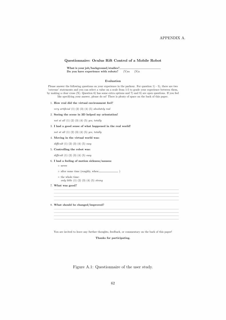
APPENDIX A.
Questionnaire: Oculus Rift Control of a Mobile Robot
What is your job/background/studies?Do you have experience with robots? (Y)es (N)o
Evaluation
Please answer the following questions on your experience in the parkour. For question 1) - 5), there are two’extreme’ statements and you can select a value on a scale from 1-5 to grade your experience between them,by making a clear cross (X). Question 6) has some extra options and 7) and 8) are open questions. If you feel
like specifying your answer, please do so! There is plenty of space on the back of this paper.
1. How real did the virtual environment feel?
very artificial (1) (2) (3) (4) (5) absolutely real
2. Seeing the scene in 3D helped my orientation!
not at all (1) (2) (3) (4) (5) yes, totally
3. I had a good sense of what happened in the real world!
not at all (1) (2) (3) (4) (5) yes, totally
4. Moving in the virtual world was:
difficult (1) (2) (3) (4) (5) easy
5. Controlling the robot was:
difficult (1) (2) (3) (4) (5) easy
6. I had a feeling of motion sickness/nausea:
◦ never
◦ after some time (roughly, when: )
◦ the whole time:only little (1) (2) (3) (4) (5) strong
7. What was good?
8. What should be changed/improved?
You are invited to leave any further thoughts, feedback, or commentary on the back of this paper!
Thanks for participating.
Figure A.1: Questionnaire of the user study.
62