octobox roaming/handover test application...
TRANSCRIPT
octoBox™ Roaming/Handover Test Application Note
Automated test that uses RF attenuators to create physical layer
conditions for roaming; supports Wi-Fi and cellular test networks
A stack of 3 octoBoxes can be configured as a roaming testbed with the OB-ROAMING software controlling test
traffic and programmable attenuators to create conditions for the roaming events. The same testbed can also be
used to measure throughput vs. range.
OB-ROAMING TEST HIGHLIGHTS
Stand-alone compact RF testbed supports Wi-Fi (802.11a/b/g/p/n/ac) and cellular (GSM, UMTS, LTE, FDD, TD-LTE and LTE-Advanced) testing
Detects ‘sticky’ Wi-Fi clients with slow path loss ramping Supports throughput vs. range measurements Factory configured with RF attenuators, combiners and
cabling needed for the roaming and throughput testing Better than 80 dB of isolation at close range; all power and
control interfaces are filtered to ensure isolation 8 RF ports per octoBox accommodate 4x4 MIMO plus
controlled interference or monitor connections Automated OB-ROAMING test software
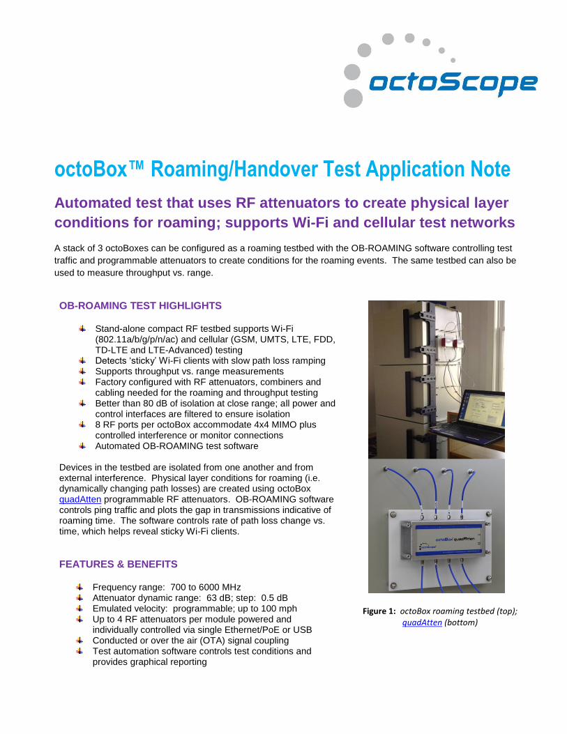
Devices in the testbed are isolated from one another and from external interference. Physical layer conditions for roaming (i.e. dynamically changing path losses) are created using octoBox quadAtten programmable RF attenuators. OB-ROAMING software controls ping traffic and plots the gap in transmissions indicative of roaming time. The software controls rate of path loss change vs. time, which helps reveal sticky Wi-Fi clients.
FEATURES & BENEFITS
Frequency range: 700 to 6000 MHz Attenuator dynamic range: 63 dB; step: 0.5 dB Emulated velocity: programmable; up to 100 mph Up to 4 RF attenuators per module powered and
individually controlled via single Ethernet/PoE or USB Conducted or over the air (OTA) signal coupling Test automation software controls test conditions and
provides graphical reporting
Figure 1: octoBox roaming testbed (top); quadAtten (bottom)
Roaming Application Note +1.978.222.3114 www.octoscope.com
How does the octoBox roaming test work?
The client/UE is connected to each AP/BS1 via programmable RF attenuators. 4x4 MIMO links are set up using
octoBox quadAtten modules with 4 individually programmable RF attenuators.
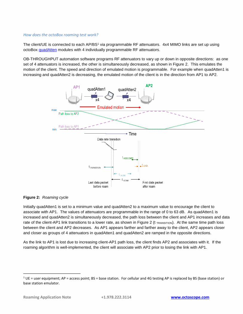
OB-THROUGHPUT automation software programs RF attenuators to vary up or down in opposite directions: as one
set of 4 attenuators is increased, the other is simultaneously decreased, as shown in Figure 2. This emulates the
motion of the client. The speed and direction of emulated motion is programmable. For example when quadAtten1 is
increasing and quadAtten2 is decreasing, the emulated motion of the client is in the direction from AP1 to AP2.
Figure 2: Roaming cycle
Initially quadAtten1 is set to a minimum value and quadAtten2 to a maximum value to encourage the client to
associate with AP1. The values of attenuators are programmable in the range of 0 to 63 dB. As quadAtten1 is
increased and quadAtten2 is simultaneously decreased, the path loss between the client and AP1 increases and data
rate of the client-AP1 link transitions to a lower rate, as shown in Figure 2 (t TRANSITION). At the same time path loss
between the client and AP2 decreases. As AP1 appears farther and farther away to the client, AP2 appears closer
and closer as groups of 4 attenuators in quadAtten1 and quadAtten2 are ramped in the opposite directions.
As the link to AP1 is lost due to increasing client-AP1 path loss, the client finds AP2 and associates with it. If the
roaming algorithm is well-implemented, the client will associate with AP2 prior to losing the link with AP1.
1 UE = user equipment; AP = access point; BS = base station. For cellular and 4G testing AP is replaced by BS (base station) or base station emulator.

Roaming Application Note +1.978.222.3114 www.octoscope.com
What test results does the software produce?
The OB-ROAMING software generates IP layer pings between 2 Linux PCs in the testbed. The ping traffic is
bidirectional through the client under test. During a roam the ping responses are interrupted and the gap in the ping
responses is plotted along with programmable attenuator ramp, as shown in Figure 3. The attenuator start, stop and
duration values are all programmable.
Figure 3: OB-ROAMING test results (left) and test configuration (right).
The Ping PCs (Figure 3, right) are pinging each other, creating bi-directional traffic. If the client under test is capable
of pinging, only one external Ping PC is required. If the client is a bridge, an external Ping PC sends pings through
this bridge to its partner PC.
Each device can couple into the wireless test network either over the air (OTA) or via cabling (conducted). Link
budgets will vary based on the type of coupling, OTA or conducted, and will need to be calculated.
How do quadAtten modules work in the testbed?
Each quadAtten module provides 4 individually programmable attenuators and creates a 4x4 MIMO link having
programmable path loss. quadAtten module can be powered and programmed from the Console PC via either
Ethernet/POE port or USB port. The quadAtten Ethernet and USB ports are filtered, enabling high isolation and
permitting the quadAtten module to be mounted outside of the octoBox for convenient access and without coupling
external interference into the testbed as most other attenuators would.
MPE (multipath emulator) is an optional module that adds multipath to the links in the testbed to make conditions
more realistic for the devices being tested.
How can I measure throughput with this testbed?
Refer to our OB-THROUGHPUT documentation for a description of our automated throughput vs. range
measurement software. It controls quadAtten, turn table (optional) and traffic generation and creates Excel plots of
throughput vs. range. Throughput vs. range vs. orientation plots are also available with the turn table octoBox model.
Roaming Application Note +1.978.222.3114 www.octoscope.com
What does the automation software control?
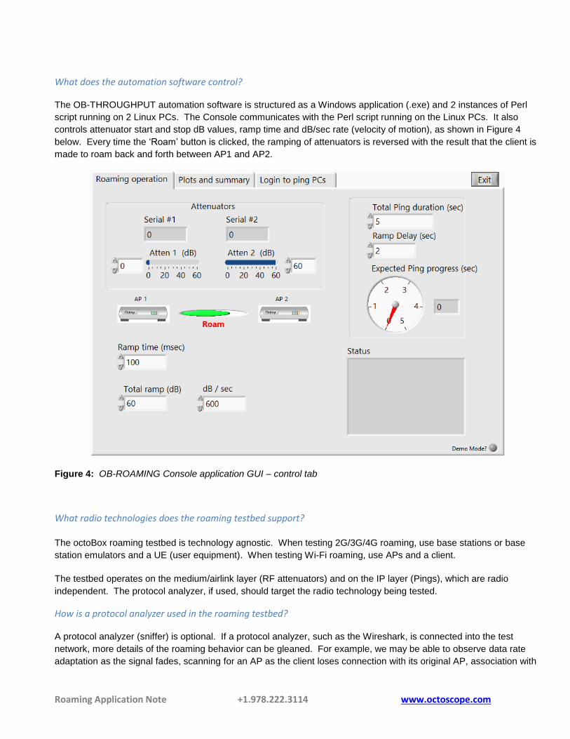
The OB-THROUGHPUT automation software is structured as a Windows application (.exe) and 2 instances of Perl
script running on 2 Linux PCs. The Console communicates with the Perl script running on the Linux PCs. It also
controls attenuator start and stop dB values, ramp time and dB/sec rate (velocity of motion), as shown in Figure 4
below. Every time the ‘Roam’ button is clicked, the ramping of attenuators is reversed with the result that the client is
made to roam back and forth between AP1 and AP2.
Figure 4: OB-ROAMING Console application GUI – control tab
What radio technologies does the roaming testbed support?
The octoBox roaming testbed is technology agnostic. When testing 2G/3G/4G roaming, use base stations or base
station emulators and a UE (user equipment). When testing Wi-Fi roaming, use APs and a client.
The testbed operates on the medium/airlink layer (RF attenuators) and on the IP layer (Pings), which are radio
independent. The protocol analyzer, if used, should target the radio technology being tested.
How is a protocol analyzer used in the roaming testbed?
A protocol analyzer (sniffer) is optional. If a protocol analyzer, such as the Wireshark, is connected into the test
network, more details of the roaming behavior can be gleaned. For example, we may be able to observe data rate
adaptation as the signal fades, scanning for an AP as the client loses connection with its original AP, association with
Roaming Application Note +1.978.222.3114 www.octoscope.com
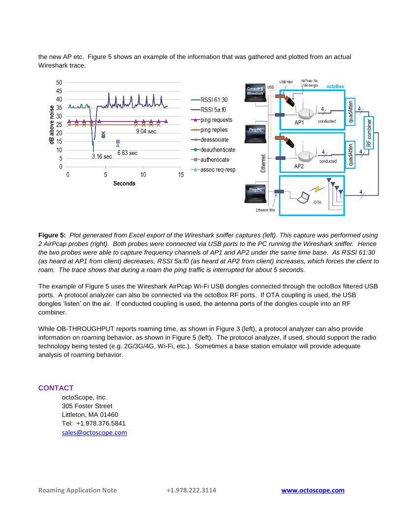
the new AP etc. Figure 5 shows an example of the information that was gathered and plotted from an actual
Wireshark trace.
Figure 5: Plot generated from Excel export of the Wireshark sniffer captures (left). This capture was performed using
2 AirPcap probes (right). Both probes were connected via USB ports to the PC running the Wireshark sniffer. Hence
the two probes were able to capture frequency channels of AP1 and AP2 under the same time base. As RSSI 61:30
(as heard at AP1 from client) decreases, RSSI 5a:f0 (as heard at AP2 from client) increases, which forces the client to
roam. The trace shows that during a roam the ping traffic is interrupted for about 5 seconds.
The example of Figure 5 uses the Wireshark AirPcap Wi-Fi USB dongles connected through the octoBox filtered USB
ports. A protocol analyzer can also be connected via the octoBox RF ports. If OTA coupling is used, the USB
dongles ‘listen’ on the air. If conducted coupling is used, the antenna ports of the dongles couple into an RF
combiner.
While OB-THROUGHPUT reports roaming time, as shown in Figure 3 (left), a protocol analyzer can also provide
information on roaming behavior, as shown in Figure 5 (left). The protocol analyzer, if used, should support the radio
technology being tested (e.g. 2G/3G/4G, Wi-Fi, etc.). Sometimes a base station emulator will provide adequate
analysis of roaming behavior.
CONTACT
octoScope, Inc.
305 Foster Street
Littleton, MA 01460
Tel: +1.978.376.5841