october 1985 surface fatigue life and failure …...nasa technical paper 2513 1985 nattonal...
TRANSCRIPT

NASATechnical
Paper2513
October 1985
Surface Fatigue Life andFailure Characteristics
of EX-53, CBS 1000M, andAISI 9310 Gear Materials
Dennis P. Townsend
https://ntrs.nasa.gov/search.jsp?R=19860003141 2020-04-10T10:14:43+00:00Z

NASATechnicalPaper2513
1985
Nattonal Aeronauhcsand Space Adm_npstrat_on
Scienlilic and TechnicalInformation Branch
Surface Fatigue Life andFailure Characteristics
of EX-53, CBS 1000M, andAISI 9310 Gear Materials
Dennis P. Townsend
Lewis Research Center
Cleveland, Ohio


Summary
Spur gear endurance tests and rolling-element surface
fatigue tests were conducted to investigate EX-53 and
CBS 1000M steels for use as advanced application gearmaterials, to determine their endurance characteristics,
and to compare the results with the standard AISI 9310
gear material. The gear pitch diameter was 8.89 cm (3.5
in). Test conditions were an oil inlet temperature of 320 K
(116 °F), an oil outlet temperature of 350 K (170 °F), a
maximum Hertz stress of 1.71 GPa (248 ksi), and a speed
of l0 000 rpm. Bench-type rolling-element fatigue tests
were conducted at ambient temperature with a bar
specimen speed of 12 500 rpm and a maximum Hertzstress of 4.83 GPa (700 ksi).
The EX-53 test gears had a gear surface fatigue life oftwice that of the AISI 9310 spur gears. The CBS 1000M
test gears had a surface fatigue life of more than twice
that of the AISI 9310 spur gears. However, the CBS
1000M gears experienced a 30-percent tooth fracture
failure which limits its use as a gear material. The rolling-
contact fatigue lives of RC bar specimens of EX-53 and
AISI 9310 were approximately equal. However, the CBS
1000M RC specimens had a surface fatigue life about 50
percent of that of the EX-53 and AISI 9310.
Introduction
In recent years several steels have been developed for
gear and hearing applications that have improvedstrength and improved hot hardness capabilities (refs. 1
and 2). Along with the materials development there has
been an increasing demand by aircraft manufacturers and
others for gear and bearing steels that will give improved
life at normal operating temperatures and allow
operation of geared systems and jet engines at higher
operating temperatures. With improved hot hardness in a
gear material, the gears can operate at higher loads withless scoring and can operate at higher temperatures
without reduction in surface fatigue life or spallingfailures.
It is normally considered that a bearing or gearmaterial must have a hardness of at least 58 Rockwell C
to have a good surface fatigue life. The standard gear
material AISI 9310 now used in the aircraft industry
begins to lose its hardness above 394 K (250 °F) (refs. 3
and 4). Therefore, a better hot hardness material is
necessary for operation above this temperature. A good
gear material should have a hard case for resistance to
surface fatigue and a tough core for resistance to bending
fatigue and impact loading. For this reason, most gearsteels are case hardened and have a medium hard core for
improved fracture toughness and resistance to bendingfailures.
Two recently developed carburizing grade steels that
have shown good possibilities for gears and bearings are
the EX-53 and the CBS 1000M (refs. 3 and 4). The EX-53
steel has good hot hardness to 505 K (450 °F) and has
good fracture toughness (ref. 4). The CBS 1000M hasgood hot hardness to 589 K (600 °F) and medium
fracture toughness (refs. 3 to 5). Because of this good hot
hardness plus good machinability and ease of
carburizing, the EX-53 and CBS 1000M show promise
for use as gear materials in advanced aircraft applications
such as turbo-prop and helicopter main-drive gearboxes.
The objectives of the research reported herein were (1)
to investigate EX-53 and CBS 1000M for use as gearmaterials, (2) to determine the surface endurance
characteristics of EX-53 and CBS 1000M, and (3) to
compare the results with the standard AISI 9310 gear
material. To accomplish these objectives, tests were
conducted with one lot each of spur gears made from a
single heat each of EX-53 and CBS 1000M. For
comparison purposes, one lot of spur gears
manufactured from a single heat of AISI 9310 was also
tested. The gear pitch diameter was 8.89 cm (3.50 in).
Test conditions included an oil inlet temperature of 320 K(116 °F) that resulted in an oil outlet temperature of 350
K (170 °F), a maximum Hertz stress of 1.71 GPa (248
ksi), and a shaft speed of 10 000 rpm. Also, bench-type
rolling-element fatigue tests were conducted with one loteach of EX-53 and AISI 9310 and three lots of CBS
1000M test bars (ref. 6). These tests were run at ambient
temperatures with a bar specimen speed of 12 500 rpm
and a maximum Hertz stress of 4.38 GPa (700 ksi).
The RC bar rolling-element fatigue tests were
conducted as a quick and inexpensive method of
generating rolling-contact (RC) surface fatigue datawhich could be compared to the gear surface fatigue data
for possible correlation. The surface fatigue test results
are plotted on Weibull graphs for comparision of the 10-

and 50-percent life of the gears or RC bars. A test was
considered complete when a fatigue spall occurs which
was equal to or greater than one-half the width of the
running surface.
Apparatus and Procedures
Gear Test Apparalus
The gear fatigue tests were performed in the NASA
Lewis Research Center's gear fatigue test apparatus (fig.
1). This test rig uses the four-square principle of applying
the test gear load so that the input drive only needs to
overcome the frictional losses in the system.
A schematic of the test rig is shown in figure l(b). Oil
pressure and leakage flow are supplied to the load vanes
through a shaft seal. As the oil pressure is increased on
the load vanes inside the slave gear, torque is applied to
the shaft. This torque is transmitted through the test
gears back to the slave gear where an equal but opposite
torque is maintained by the oil pressure. This torque on
the test gears, which depends on the hydraulic pressure
(a)
Slave-systemOil-seal gas flow / oil inlet
Viewing _ ,/"_ _ 7' r Drive
port 7, _\ _ " _ [ / shaft
_ _ _ _ _ / ,- Shaft//"_ I _|i ,' , oil
IH I " / sealTest-lubricant ._"\_ !L _JT_ ..... _ __ ._. _/ /
[_ a i1 _ _ "_ Load pressure
Test- ,>. _,_L_.._-_7_, , ...... "%
cover-lt"_" _ "_ [" _7', 0,1.
gears yTest-lubricant / _ ....
outlet temperature / _- . -_
measurement location _ _ ......
7Slave geari- Drive shaft/
i /- Belt pulley/ /I
Test _<'gears
(b)
II
Offset
I
Loading
vanes
Slave-gear
,:--Shaft seal Loading _ torque,\ vane - -_.._-_
/ //L / /
Load / C0-11421-[5
pressure-"
(a) Cutaway view.
(b) Schematic diagram.
Figure I.--NASA Lewis Research Center's gear fatigue test apparatus.

applied to the load vanes, loads the gear teeth to thedesired stress level. The two identical test gears can be
started under no load, and the load can be applied
gradually without changing the running track on the gearteeth.
Separate lubrication systems are provided for the test
gears and the main gearbox. The two lubricant systems
are separated at the gearbox shafts by pressurized
labyrinth seals. Nitrogen is the seal gas. The test gearlubricant is filtered through a 5-t_m nominal fiberglass
filter. The test lubricant can be heated electrically with an
immersion heater. The skin temperature of the heater is
controlled to prevent overheating the test lubricant.A vibration transducer mounted on the gearbox is used
to automatically shut off the test rig when a gear surface
fatigue occurs. The gearbox is also automatically shut offif there is a loss of oil flow to either the main gearbox or
the test gears, if the test gear oil overheats, or if there is a
loss of seal gas pressurization.
The belt-driven test rig can be operated at several fixed
speeds by changing pulleys. The operating speed for the
tests reported herein was 10 000 rpm.
Rolling-Contact (RC) Fatigue Tester
The rolling-contact (RC) fatigue tester is shown in
figure 2. A cylindrical test bar is mounted in the precisionchuck. The drive motor attached to the chuck drives the
Lubricator
Yoke
I
_i-- Loadcell
Vibration_"-.+ pickupTest
bar which in turn drives two idler disks. Load is applied
by closing the disks against the test bar using amicrometer-threaded turnbuckle and a calibrated load
cell. Lubrication is supplied by a drop feed system using aneedle valve to control the flow rate. Several test runs can
be made on one test bar by moving the bar position in theaxial direction relative to disk contacts. The test bar is
rotated at 12 500 rpm and receives 25 000 stress cycles perminute. The maximum Hertz stress was 4.83 GPa (700
ksi).
Test Gears
A photograph of the test gears is shown in figure 3.The dimensions of the gears are given in table 1. All gearshave a nominal surface finish on the tooth face of 0.41
#m (16 #in) rms. All the gears have a standard 20 +
involute profile with tip relief. The tip relief was 0.0013
cm (0.0005 in) starting at the highest point of single tooth
contact.
Rolling-Contact (RC) Test Bar Specimens
The test specimens for the RC fatigue tester were
cylindrical bars 7.6 cm (3.0 in) long with a 0.952-cm(0.375-in) diameter. The surface finish was 0.13 to 0.2 #m
(5 to 8 #in) rms.The large mating disks had a diameter of 19 cm (7.5 in)
and a crown radius of 0.635 cm (0.250 in). The surface
finish of the disks was the same as the test bars.
Test Materials
AISI 9310 baseline gears and RC bars weremanufactured from consumable-electrode vacuum-
melted (CVM) or vacuum-arc-remelted (VAR) AISI9310.
The CBS 1000M test gears and RC bars weremanufactured from three lots of VAR CBS 1000M. The
nominal chemical composition of the material for the
gears and bars is given in table II. The heat treatment forthe gears and bars material is given in table III. The case
and core properties of the materials are given in table IV.
•Idler roller
CD-I_IO
Figure 2.--Rolling-contact fatigue tester. Figure 3.--Test-gear configuration.

TABLE 1. (;EAR DATA
[Gear tolerance per AGMA class 12.]
Number of teeth ..................................................................................... 28
Diametral pilch ....................................................................................... 8
( ircular pitch, cm (in) ............................................................. 0.9975 (0.3927)
Whole depth, cm (in) ................................................................. 0.762 {0.300)
Addendum, cm {inJ ................................................................... 0.318 (0.125)
Chordal toolh thickness reference, cm (in) ...................................... 0.485 (0.191)
Pressure angle, deg ................................................................................. 20
Pitch diameter, cm (in) ............................................................... 8.890 (3.500)
Outside diameter, cm (m) ........................................................... 9.525 (3.750)
Root fillet, cm (in) .................................................... 0.101o 0.15 (0.04 to 0.061
Measurement over pins, cm {in) ........................... 9.603 to 9.630 (3.7807 to 3.7915)
Pin diameter, cm (in_ ................................................................. 0.549 {0.2161
Backlash reference, cm {in) ......................................................... 0.025 (0.010)
"Tip relief, cm (inl ................................................................... 0.0013 10.00,051
Tooth vddth, cm fin) .................................................................... 0.64 (0.25}
TABLE II.--CHEMICAL COMPOSITION OF TEST MATERIALS
BY PERCENT WEIGHT
Element AISI AISI Ex-53 CBS IOOOM
9310 9310 gears
RC gears and Gears Bars
bars bars
A and B C
Carbon (core) 0.11 0.11 O. 10 0.14 0.135 0.14
Manganese .69 .58 ,37 .48 .48 ,48
Phosphorus .005 .003 .009 .018 .018 .018
Sulfur .002 .004 .006 .019 ,019 .019
Silicon .30 .26 .98 .43 .43 .43
Copper .07 .21 2.07 --- .15 ......
Chromium 1.24 1.38 t.05 1.12 1.12 1,12
Molybdenum .11 .13 3.30 4.77 4,77 4.77
Vanadium .......... .12 .I .33 .....
Nickel 3.19 3.2 2.13 2.94 2.94 2.94
Iron Balance Balance Balance Balance Balance Balance
FABLE III.--HEAT TREATMENT PROCEDURE FOR MATERIAL TESTED
_lep Process
Preheat
Carburize
Temper
Austenize or
harden
Temper
Deep freeze
Temper
AISI 9310
1172 K (1650 °F)
for 8 hr
922 K {1200 °F)
lot 10 hr
1088 K 0500 +F)
for 2.5 hr
EX-53
870 K (1100 "F)
1172 K (1650 °F)
tor 5 hr
894 K (1150 °F)
fur 2 hr
1180 K (1675 °F)
for 0.5 hr
190 K (- 120 *F) 200 K (- 100 °F)
for 3.5 hr for 1 hr
450 K (350 °E) 505 K (450 *F)
for 2 hr for 2 +2+2 hr
CBS 1000M
Gears Bars
A B C
1228 K (1750 °F)
in air for 0.5 hr
1228 K (1750 °F)
for 8 hr
755 K (9(RI °F)
for 1.5 hr
Preheal at
IO90 K (1500 "F)
then equalize at
1366 K (2{XKI °F)
for 10 rain
644 K {700 °Ft
for 1 hr
20OK (IOO*F)
for I hr
811 K (I(XX) °Ft
for 2,2+2hr
1228 K (1750 *F)
in air for 1 hr
1227 K (1750 °F}
for 11 hr
1366 K (2000°F)
811K (1000 °F)
for2+2+2hr
1241K (1775 *F)
in vacuum for I hr
1214 K (1725 *E)
for 10 hr
1089 K (1500 *F)
1366K (2000 *F)
644 K (700 °F)
for 1 hr
200K( IOO *F)
for 1 hr
811 K (1000 *F)
for 2+2+2hr
866 K Ill00 *F)
in air for 2 hr
1200 K 11700 *El
for2 hr
1089 K (1500 OF)
in vacuumfor 0.25 hr
1380 K (2025 °F)
200 K ( - IO0 °F)
for I hr
811 K (1000 °F)
for 2+2.2hr
I,A.BI1: IV.--(ASE AND ('()RE CHARACTERISTICS
Malerial
[!X-53 gears and bars
9310 gears
Bars
('BS 10(_)M gears
Bars A
liars B
Bars C
Effective Case (;ore Case retained
case deplh hardness, hardness, ausfinite,
to R(" 5, RC RC percent
mm (in)
1.02 (0.040) 61 40
.81 (•(132) 61 38
g4 ( .033) 61.4 38
1.52( .060t 62 51
1.09 ( .0431 61.6 47
76 ( .030) 60.9 47
.76 ( .030) 60.5 41
21
I0
11.2
1.7
.4
0
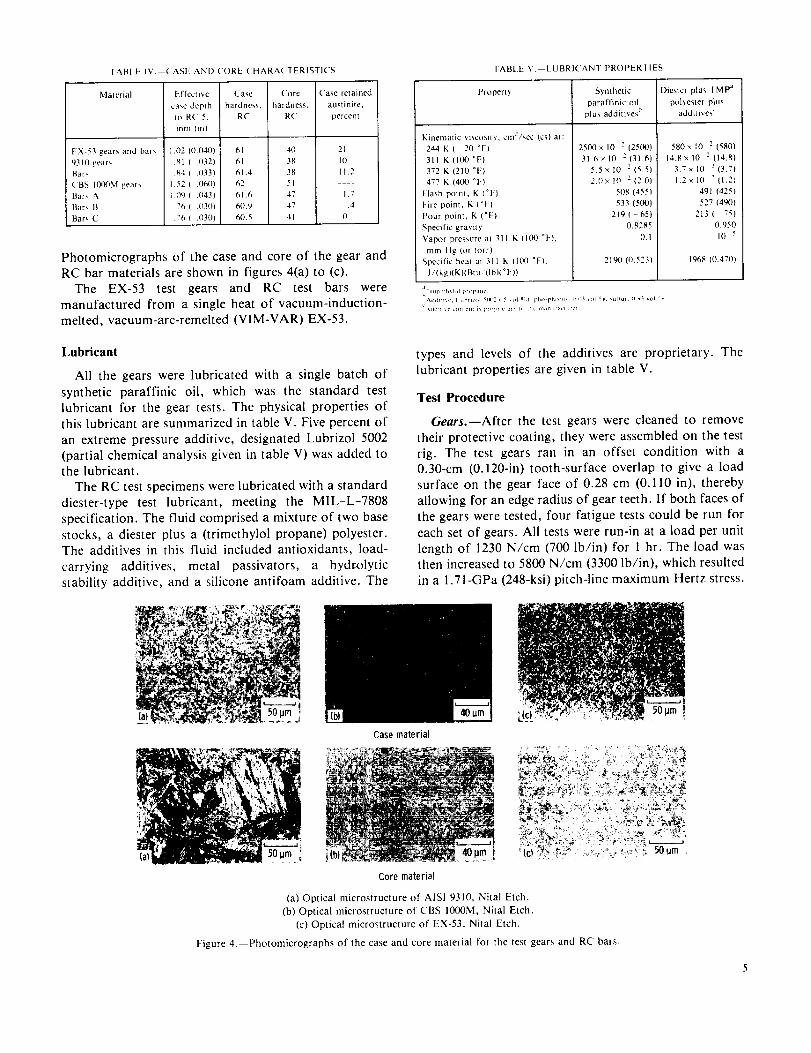
Photomicrographs of the case and core of the gear andRC bar materials are shown in figures 4(a) to (c).
The EX-53 test gears and RC test bars were
manufactured from a single heat of vacuum-induction-
melted, vacuum-arc-remelted (VIM-VAR) EX-53.
TABt.E V. LUBRICANT PROPERTIES
Properl) Synthetic Diester plus TMP a
paraffinic oil polyester plus
plus addt wes additives"
Kinematic viscosity, cm?/sec (CS)at:
244 K( 20 °F)
311 K (100 _F)
372 K (210 °F)
477 K (400 °F)
Flash poinl, K (°F)
['ire point, K (°t:}
Pour point, K ("t:)
Specific gravity
Vapor pressure al 311 K II00 °F),
mm Hg (or torr}
Specific heat al 311 K [IOO °F),
J/tkg)(K)(Bm / (lbl(° F))
2500×10 2 [2500)
31.6×10 2(31.6}
5.5×10 2 (5.5}
2.0x I0 2(2.0}
508 (455}
533 {5OO}
219 ( 65}
0.8285
0.1
2190 (0.523)
580xi0 : 1580}
14.8×10 : [14.8}
3.7 x 10 : (3.7}
1.2×10 : {I.2)
491 (425)
527 (49(1)
213 (75)
0.950
10 _
196g (0.470}
Lubricant
All the gears were lubricated with a single batch of
synthetic paraffinic oil, which was the standard test
lubricant for the gear tests. The physical properties ofthis lubricant are summarized in table V. Five percent of
an extreme pressure additive, designated Lubrizol 5002
(partial chemical analysis given in table V) was added tothe lubricant.
The RC test specimens were lubricated with a standard
diester-type test lubricant, meeting the MIL-L-7808
specification. The fluid comprised a mixture of two base
stocks, a diester plus a (trimethylol propane) polyester.The additives in this fluid included antioxidants, load-
carrying additives, metal passivators, a hydrolytic
stability additive, and a silicone antifoam additive. The
Casematerial
types and levels of the additives are proprietary. Thelubricant properties are given in table V.
Test Procedure
Gears.--After the test gears were cleaned to remove
their protective coating, they were assembled on the 'test
rig. The test gears ran in an offset condition with a0.30-cm (0.120-in) tooth-surface overlap to give a load
surface on the gear face of 0.28 cm (0.110 in), thereby
allowing for an edge radius of gear teeth. If both faces of
the gears were tested, four fatigue tests could be run for
each set of gears. All tests were run-in at a load per unit
length of 1230 N/cm (700 lb/in) for 1 hr. The load wasthen increased to 5800 N/cm (3300 lb/in), which resulted
in a 1.71-GPa (248-ksi) pitch-line maximum Hertz stress.
Corematerial
(a) Optical microstructure of ANSI 9310, Nita] Etch.
(b) Optical microstructure of CBS IO00M, Nital Etch.
(c) Optical microstructure of EX-53, Nital Etch.
Figure 4.--Photomicrographs of the case and core material for the test gears and RC bars.

At the pitchline load the tooth bending stress was 0.21
GPa (30 ksi) if plain bending was assumed. However,because there was an offset load, there was an additional
stress imposed on the tooth bending stress. Combining
the bending and torsional moments gave a maximum
stress of 0.26 GPa (37 ksi). This bending stress did notinclude the effects of tip relief which would also increase
the bending stress.
Operating the test gears at 10 000 rpm gave a pitchlinevelocity of 46.55 m/sec (9163 ft/min). Lubricant was
supplied to the inlet mesh at 800 cm3/min (49 in3/min)
and 320 ± 6 K (116 ± 10 *F). The lubricant outlet temper-ature was nearly constant at 350±3 K (170±5 *F). The
tests ran continuously (24 hr/day) until the rig wasautomatically shut down by the vibration detection
transducer (located on the gearbox adjacent to the test
gears) or until 500 hr of operation without failure were
completed. The lubricant circulated through a 5-#mfiberglass filter to remove wear particles. For each test,3.8 liters (1 gal) of lubricant were used. At the end of each
test, the lubricant and filter element were discarded. Inlet
and outlet oil temperatures were continuously recordedon a strip-chart recorder.
The pitchline elastohydrodynamic (EHD) filmthickness was calculated by the method of reference 7. It
was assumed, for this film thickness calculation, that the
gear temperature at the pitchline was equal to the outlet
oil temperature and that the inlet oil temperature to the
contact zone was equal to the gear temperature, even
though the oil inlet temperature was considerably lower.
It is possible that the gear surface temperature was evenhigher than the oil temperature, especially at the end
points of sliding contact. The EHD film thickness for
these conditions was computed to be 0.33 /_m (13 _in),
which gave an initial ratio of film thickness to composite
surface roughness (h/a) of 0.55 at the 1.71-GPa (248-ksi)pitchline maximum Hertz stress.
Each pair of gears was considered as a system and,
hence, a single test. Test results were evaluated usingWeibull plots calculated by the method of Johnson (ref.
8). (A Weibull plot is the number of stress cycles versus
the statistical percent of gear systems failed.)
RC tests.--Fatigue testing was also performed in theRC rig. The test bar was installed and the disks were
brought against the bar using the turnbuckle. The load
applied was sufficient to allow the bar to drive the
contacting disks, and the bar was accelerated to the12 500 rpm test speed.
When the disks and test bar were in thermal
equilibrium at a bar temperature of -305 K (90 *F), the
full load of 1250 N (281 lb) was applied to give the test
bar a maximum Hertz stress of 4.83 GPa (700 ksi). When
a fatigue failure occurred, the rig and related
instrumentation were automatically shut clown by a
vibration detection system. The axial position of the test
bar in the drive chuck was changed to use a new runningtrack before testing was resumed. Test results were also
evaluated according to the methods of reference 8.
Results and Discussion
Gear Life Results
One lot each of VAR CBS 1000M, VIM-VAR EX-53,and CVM AISI 9310 spur gears was endurance tested.
Test conditions were a tangential tooth load of 5800
N/cm (3300 lb/in), which produced a maximum Hertz
stress of 1.71 GPa (248 ksi), and a speed of 10 000 rpm.
The gears failed either by classical subsurface pitting
fatigue or tooth bending fracture. The pitting fatigue liferesults of these tests are shown in the Weibull plots offigure 5 and are summarized in table VI.
Pitting fatigue life results for the gears made from the
CVM AISI 9310 material are shown in figure 5(a). The10- and 50-percent lives were 18.8×10⁶ and 46×106
stress cycles (31 and 77 hr), respectively. The failure index
(i.e., the number of fatigue failures out of the number of
sets tested) was 18 out of 19. A typical fatigue spall that
occurs near the pitchline is shown in figure 6. This spall is
similar to those observed in the rolling-element fatiguetests. The pitchline pitting is the result of a high
subsurface shearing stress which develops subsurfacecracks. The subsurface cracks propagate into a crack
network which results in a fatigue spall that is slightlybelow the pitchline where the sliding condition is moresevere.
Pitting fatigue life results for the gear systems made
from VAR CBS 1000M material are shown in figure 5(b).The 10- and 50-percent lives were 44.4 × 10⁶ and 116 × 106
stress cycles (74 and 193 hr), respectively. The failureindex was 17 out of 21. There were 7 tooth fracture
failures out of the 21 tests, 2 of which were fractures
without prior fatigue spalls. Four of the tooth fractures
were initiated by a fatigue spall--i.e., the tooth fracture
originated at a fatigue spall. Figure 7 shows a typicalfatigue spall and tooth fractures for the VAR CBS
1000M. The two fractures without fatigue spalls were
considered suspensions as were two tests that completedover 500 hr without failure. The six tooth fractures with
this material are an indication of its low fracture
toughness and would, therefore, limit its use as an
aircraft gear material. In contrast, none of the CVM
AISI 9310 or VIM-VAR EX-53 gears failed by tooth
fracture. The 10-percent surface fatigue life of the VAR
CBS 1000M gears was approximately twice that of the
standard CVM AIS1 9310 gears. The confidence number
was 91 percent, which indicates that the difference isstatistically significant. (The confidence number indicates
the percentage of time the relative lives of the material

O
E
8
99
95
80
60
4O
20
108
6
00
0
0
CBSI_0M
CVM AISI 9310
O
VAR CBS 1000M
Broken toothwith fatiguespall
_" Broken toothwithout fatiguespall
0 _ Runout
0
i [ I l i
®
I i [ l
lO
8
6
CVM AISI9310
VIM-VAR EX-53
CVM AISI 9310 -',N
VIM-VAREX-53
O
O
2 I i I i I l I J8 I0 20 40 60 80 i00 200 400 500xlO6 8 I0 20 40 60 80 i00 200 400 500x106
Gear life, revolutions
(a) £VM AISI 9310.(b) VAR CBS 1000M.
(c) V1M-VAR EX-53.
(d) Summary.
Figure 5.--Surface fatigue lives of carburized and hardened CVM AISI 9310, VIM-VAR EX-53, and VAR CBS 1000M test gears. Speed, l0 000
rpm; maximum Hertz stress, 1.71 GPa (250 ksi); temperature, 350 K (170 °F); lubricant, synthetic paraffinic with 5-percent EP additive.

TABLE VI.--SPUR GEAR FATIGUE I.IFE RESULTS
[Pitch diameler, 8.89 cm (3.30 in); maximum Hertz stress, 1.71 GPa (248 ksi); speed,
10 000 rpm; lubricant, synthetic paraffinic oil; gear temperalure, 350 K (170 OF).]
Material Gear Syslem lile, Weibull
revolutions slope
10-percent 50-percent
life life
AISI 9310 18.8× 10 6 46× 106
EX-53 40× 106 134× I0 _
CBS IO(OM 44.4 × IO t' I16× I0 _
2.1
1.5
1.97
NUlllbcr tll _urt_l¢_"Pat_gucfailure, _+ , n bc _ gealr Eestcd
Failure Confidence
index number al
(a) 10-percenl
level h
18 out of 19 ---
15 out of 21 87
17 out of 21 91
I'er_enlagt" t_t time chat /0 percent hr¢ obtained _JEh -MSI 9310 gears _i[I h_s_"Ih_",;Imc rclaEion IO_heIO pcrcem II1¢_btained with LX 53 gear_ or (BS IO_P..I
Figure 6.--Typical fatigue spall for AISI 9310 gears.
will occur in the same order.) Since the material has a
high temperature hardness above RC 58 to about 533 K
(500 °F) (ref. 3), it would be an excellent gear material if
the fracture toughness could be improved.
The pitting fatigue life results for the gear systemsmanufactured from VIM-VAR EX-53 material are
shown in figure 5(c). The 10- and 50-percent fatigue liveswere 40 x 10 6 and 134 x 10 6 stress cycles (67 and 223 hr),
respectively. The failure index was 15 out of 21. Figure 8is a typical fatigue spall for the EX-53 gear material. Six
of the 21 tests were suspensions after completing over
300× 106 stress cycles (500 hr) without failure. There
were no tooth fractures with this material even though
several tests were run for several hours after a fatiguespall. This is a good indication of the good fracture
toughness of the VIM-VAR EX-53 gear material as
reported in reference 4. The surface fatigue life of the
VIM-VAR EX-53 was approximately twice that of theCVM AISI 9310 standard gear material with a confidence
number of 87 percent, which is considered statistically
significant. The gear life data are summarized in figure5(d).
(a) Fatigue spall.
(b) Tooth fracture at root.
(c) Tooth fracture through fatigue spall.
Figure 7.--Gear tooth failures for CBS IOOOM.
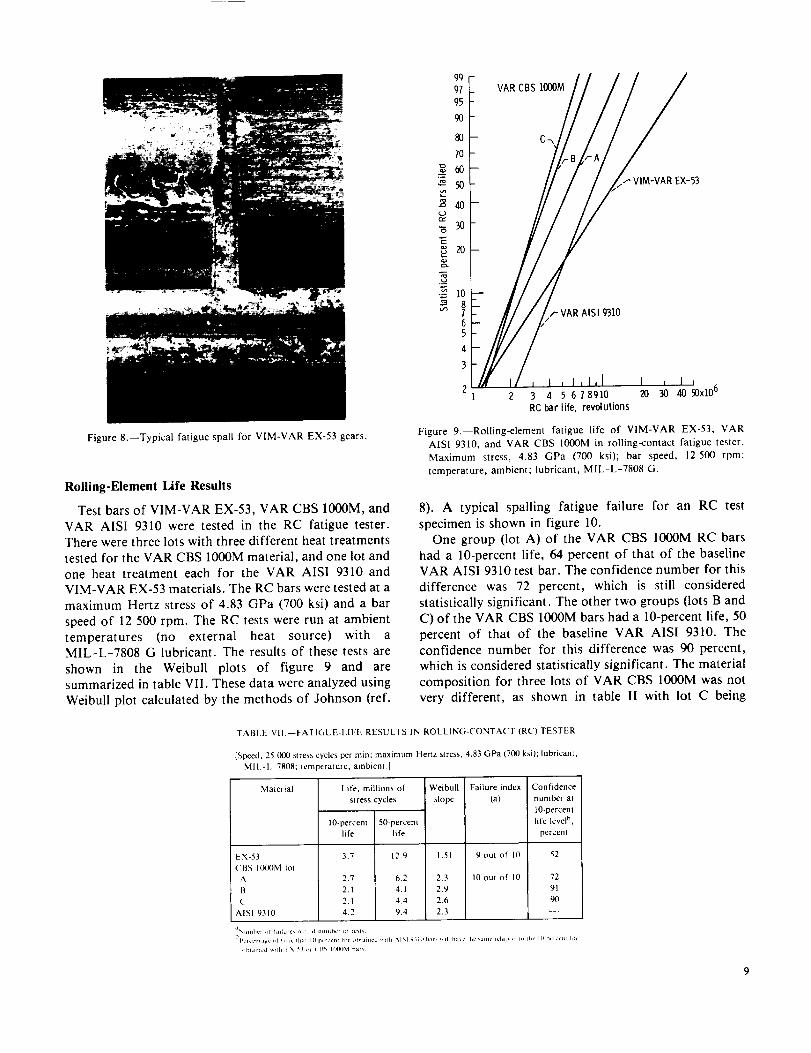
Figure &--Typical fatigue spat[ for VIM-VAR EX-53 gears.
Rolling-Element Life Results
Test bars of VIM-VAR EX-53, VAR CBS 1000M, and
VAR AISI 9310 were tested in the RC fatigue tester.There were three lots with three different heat treatments
tested for the VAR CBS 1000M material, and one lot and
one heat treatment each for the VAR AISI 9310 andVIM-VAR EX-53 materials. The RC bars were tested at a
maximum Hertz stress of 4.83 GPa (700 ksi) and a bar
speed of 12 500 rpm. The RC tests were run at ambient
temperatures (no external heat source) with aMIL-L-7808 G lubricant. The results of these tests are
shown in the Weibull plots of figure 9 and are
summarized in table VII. These data were analyzed using
Weibull plot calculated by the methods of Johnson (ref.
¢o
[:zaa
g,3
99
97
95
9O
80
l0
6O
5O
4O
3O
20
VAR CBS 1000M
- VIM-VAR E×-53
10
8 ,,- VAR AISI 931065
4
3
21 Z 3 4 5 6 78910 20 30 40_'x106
RC bar life, revolutions
Figure 9.--Rolling-element fatigue life of VIM-VAR EX-53, VAR
AISI 9310, and VAR CBS 1000M in rolling-contact fatigue tester.
Maximum stress, 4.83 GPa (700 ksi); bar speed, 12 500 rpm;
temperature, ambient; lubricant, MIL-L-7808 G.
8). A typical spalling fatigue failure for an RC test
specimen is shown in figure 10.
One group Oot A) of the VAR CBS IO00M RC bars
had a 10-percent life, 64 percent of that of the baselineVAR AISI 9310 test bar. The confidence number for this
difference was 72 percent, which is still considered
statistically significant. The other two groups (lots B andC) of the VAR CBS 1000M bars had a 10-percent life, 50
percent of that of the baseline VAR AISI 9310. The
confidence number for this difference was 90 percent,
which is considered statistically significant. The material
composition for three lots of VAR CBS 1000M was not
very different, as shown in table I| with lot C being
TABLE VII.--FATICiUE-LIFE RESULTS IN ROLLING-CONTACT (RC) TESTER
[Speed, 25 000 stress cycles per min; maximum Hertz stress, 4,83 GPa (700 ksi); lubricant,
MII.-I. 7808; lemperature, ambienl.]
Material
EX-53
('BS H,_M }o_
A
B
C
AISI 9310
Life, millions of Weibull Failure index Confidence
slress cycles slope (a) number at
lO-percent
lO-percent 50-percent life level h,
life [i fe percent
3.7 [2,9 1.51 9 out of I0 52
2.7 6.2 2.3 10 out of IO 72
2.1 4.1 2.9 91
2.1 4.4 2.6 90
4.2 9.4 2.3 __r
%¢mlher _i tallur¢, ,_Ul L)I numbc_ Ld tcsl_
Per_cntagc _,P I,n1_' rhal IlLpcrccnt htc (pbtained _lrh SlSl 9_ ]o h._r_ _111 ha_c ihc kdlllL' Iclatlon I,_ _he I() /_'rc<[$1 ]ltc
_,blalu,:d _lEtb I \ 5_ _,u ( F_N I_KXP.,I bar_

I i
2ram
In addition, the surface temperature is even higher in the
gears because of the sliding conditions at the contactzone.
From the previous gear test data it is concluded that the
VIM-VAR EX-53 and VAR CBS 1000M materials have a
gear surface fatigue life approximately twice that of the
CVM AISI 9310. However, the rolling-contact data showthat the VIM-VAR EX-53 and VAR AISI 9310 surface
fatigue life are approximately equal, while the VAR CBS
1000M has a surface fatigue life approximately one-halfthat of VAR AISI 9310.
5Lml
400um
Figure 10.--Typical rolling-element fatigue failure.
slightly different from lots A and B. Therefore, thematerial differences would not seem to account for the
difference in the fatigue life. The heat treatment for lot Ahad several differences from lots B and C which were
fairly close to each other as shown in table II1. This
difference in heat treatment could account for the life
difference between lot A and lots B and C. From this data
the VAR CBS 1000M is considered inferior to the VAR
AISI 9310. This is not supported by the gear test datawhich show that the VAR CBS 1000M gears had a little
more than twice the fatigue life of the CVM AIS| 9310.
This difference may be the result of the different types of
contact conditions existing in the two types of tests.
The VAR EX-53 RC test bars had a rolling-contact
fatigue life that was -90 percent that of the baselineVAR AISI 9310 test bars. The confidence number for this
difference was only 52 percent, which indicates that the
difference is not statistically significant. In other words,the lives of the RC bars of EX-53 and 9310 are considered
equal. Again this conclusion is not supported by the gear
fatigue tests which say that the EX-53 has a fatigue lifetwice that of the 9310. Again it is evident that the
different contact conditions for the RC test and gear test
produce different results. In the RC rig test, pure rolling
conditions exist with a Hertz stress of 4.83 GPa (700 ksi),while in the gear test, rolling and sliding conditions exist
with a Hertz stress of 1.7 GPa (250 ksi). Anotherdifference between the two test methods is the RC bar
operating temperature, which is 305 K (90 OF), and the
test gear oil outlet temperature, which is 350 K (170 OF).
10
Summary of Results
Spur gear endurance tests and rolling-element surface-
fatigue tests were conducted to investigate VIM-VAREX-53 and VAR CBS 1000M steels for use as advanced
application gear materials, to determine their endurance
characteristics, and to compare the results with the
standard AISI 9310 gear material. Tests were conducted
with gears and RC bars manufactured from AISI 9310,
VIM-VAR EX-53, and VAR CBS 1000M. The gear pitch
diameter was 8.89 cm (3.50 in). Test conditions were an
inlet oil gear temperature of 320 K (116 OF), an oil outlet
temperature of 350 K (170 °F), a maximum Hertz stress
of 1.71 GPa (248 ksi), and a speed of 10 000 rpm. Bench-type rolling-element fatigue tests were conducted at
ambient temperature with a bar specimen speed of 12 500rpm and a maximum Hertz stress of 4.83 GPa (700 ksi).
The following results were obtained:
1. The VIM-VAR EX-53 test gears had a gear surfacefatigue life of approximately twice that of the CVM AISI
9310 spur gears.
2. The VAR CBS 1000M test gears had a surface
fatigue life of approximately twice that of the CVM AISI
9310 spur gears. However, 30 percent of the VAR CBS1000M gears experienced tooth fracture failure, which
limits the use of VAR CBS 1000M as a gear material.3. The RC fatigue lives of RC bar specimens of VIM-
VAR EX-53 and VAR AIS1 9310 were approximatelyequal.
4. In the RC tests the CBS 1000M had a surface fatiguelife about 50 percent that of the VAR AISI 9310.
Lewis Research Center
National Aeronautics and Space Administration
Cleveland, Ohio, July 16, 1985
References
1. Townsend, D.P.; and Zaretsky, E.V.: Endurance and FailureCharacteristics of Modified VASCO X-2, CBS 600 and AISI 9310Spur Gears. J. Mech. Des., vol. 103, no. 2, Apt. 1981, pp.506-515.
2. Townsend, D.P.; Bamberger, E.N.; and Zaretsky, E.V.: A Life
Study of Ausforged, Standard Forged and Standard Machined
AISI M-50 Spur Gears. J. Lubr. Technol., vol. 98, no. 3, July
1976, pp. 418-425.
3. Jatczak, Chester F.: Specialty Carburizing Steels for Elevated
Temperature Service. Met. Prog., vol. 113, no. 4, Apr. 1978, pp.
70-78.
4. Cutler, R.A.; et al.: Elevated Temperature Fracture Toughness and
Fatigue Testing of Steels for Geothermal Application. Terratek
Report TR-81-97, Oct. 1981.
5. Anderson, Neil E.; and Zaretsky, Erwin V.: Short-Term Hot-
Hardness Characteristics of Five Case Hardened Steels. NASA
TND-8031, 1975.
6. Nahm, A.G.: Rolling Element Fatigue Testing of Gear Materials.
R78AEG476, General Electric; NASA Contract NAS 3-14302)
NASA CR-135450, 1978.
7. Dowson, D.; and Higginson, G.R.: Elasto-Hydrodynamic
Lubrication. Pergamon Press, 1966.
8. Johnson, Leonard G.: The Statistical Treatment of Fatigue
Experiments. Elsevier Publishing Co., 1964.
I1


1. Report No. 2. Government Accession No. 3. Recipient's Catalog No.
NASA TP-2513
4. Title and Subtitle
Surface Fatigue Life and Failure Characteristics ofEX-53, CBS lO00M, and AISI 93|0 Gear Materials
7. Author(s)
Dennis P. Iownsend
9. Performing Organization Name and Address
National Aeronautics and Space AdministrationLewis Research CenterCleveland, Ohio 44|35
:12. Sponsoring Agency Name and Address
National Aeronautics and Space AdministrationWashington, D.C. 20546
5. Report Date
October 1985
6. Performing Organization C_e
505-42-94
8. Performing Organization Report No.
E-2578
10. Work Unit No.
11. Contract or Grant No.
13. Type of Report and Period Covered
Technical Paper
14. Sponsoring Agency Code
15. Supplementary Notes
16. Abstract
Spur gear endurance tests and rolling-element surface fatigue tests were con-ducted to investigate EX-53 and CBS lO00M steels for use as advanced applicationgear materials, to determine their endurance characteristics, and to compare theresults with the standard AISI 9310 gear material. The gear pitch diameter was8.89 cm (3.50 in). Gear test conditions were an oil inlet temperature of 320 K(116 °F), an oil outlet temperature of 350 K (]70 °F), a maximum Hertz stress of].71GPa (248 ksi), and a speed of lO 000 rpm. Bench-type rolling-elementfatigue tests were conducted at ambient temperature with a bar specimen speed of12 500 rpm and a maximum Hertz stress of 4.83 GPa (700 ksi). rhe EX-53 testgears had a surface fatigue life of twice that of the AISI 9310 spur gears. TheCBS lO00M test gears had a surface fatigue life of more than twice that of theAISI 9310 spur gears. However, the CBS ]O00M gears experienced a 30-percenttooth fracture failure which limits its use as a gear material, lhe rolling-contact fatigue lines of RC par specimens of EX-53 and AISI 9310 were approxi-mately equal. However, the CBS IO00M RC specimens had a surface fatigue life ofabout 50 percent of that of the AISI 9310.
17. Key Words (Suggested by Author(s))
Ro]ling-contact fatigue; Spur gearsfatigue; Materials: VIM-VAR EX-53;VAR CBS ]O00M; CVM AISI 93]0
18. Distribution Statement
Unclassified - unlimited
STAR Category 37
t9. Security Classif. (of this report) 20. Security Classif. (of this page)
Unclassified Unclassified21. No. of pages 22. Price
14 A02
For sale by the National Technical Information Service, Springfield, Virginia 22161
NASA-Langley, 1985