obstacle avoidance system (oas) - royal institute of ...kallej/grad_students/irvall_thesis06.pdf ·...
TRANSCRIPT

Obstacle Avoidance System (OAS)
Per Irvall
Hashimoto Lab, University of Tokyo, Japan 2006 Master thesis at S3 institute of Signals Sensors and Systems, KTH
Abstract The goal of the Master thesis was to construct an obstacle avoidance system. It was the intent ion that this system can be used as part of a bigger project performed at the lab. The system was implemented and tested for a Pioneer 2DX mobile robot in the lab environment. The posit ioning of the robot was done with an external ultrasound system provided by the lab. The Digiclops 3D camera from Gray Point research was used for main vision sensor. The code was written in C and implemented in Windows environment. The obstacle avoidance system contains image processing, map building, and control. For control, the Vector Field Histogram theory was studied and implemented. Fixed Decomposit ion was used to describe the surrounding world. The OAS system was tested for 6 different sets of obstacle environments: a single obstacle, a gate, multiple obstacles, mobile obstacles, a corridor, and a maze. Each set were designed to test the l imits of the system. All tests were recorded on video, the posit ion data and the map were saved. In all obstacle sets, the system proved successful. There was no risk for coll ision and the efficient path planning created a smooth path to the goal.

Foreword This Master thesis project is performed under the Institute S3 (Signals Sensors and Systems) at the Royal Institute of Technology, Sweden. However, the research and completion of the project wil l take place at the Hashimoto Lab, which is a part of IIS (Institute of Industrial Science) at the University of Tokyo. The exchange program between the Royal Institute of Technology and The University of Tokyo made it possible to do the research in Japan. The length of the thesis consists of 20 weeks of research. The completion of the thesis is required for graduation at the Royal Institute of Technology. I would like to take the opportunity to thank my professor in Tokyo, Hideki Hashimoto, for lett ing me come to work in his lab at Tokyo University. And I also want to thank my tutor in Tokyo, Drazen Brscic and all the other members of the lab that made it possible for me to f inish my thesis. I want to thank my tutor and examiner at Automation,S3, KTH, Stockholm associate professor Karl Henrik Johansson for his guidance. I also want to send a special thanks to the Sweden-Japan foundation for their generous contribution to this project.

Declaration of Abbreviations
OAS Obstacle Avoidance System
VFH Vector Field Histogram
SDK Software Development Kit
GPR Gray Point Research
RCP Robot Center Point

Index 1. Introduction .... . . . . . . . . . . . . . . . . . . . . . . . . . . . . . . . . . . . . . . . . . . . . . . . . . . . . . . . . . . . . . . . . . . . . . . . 1 2. Definit ion of problem .... . . . . . . . . . . . . . . . . . . . . . . . . . . . . . . . . . . . . . . . . . . . . . . . . . . . . . . . . . . 3
2.1. Restrictions.... . . . . . . . . . . . . . . . . . . . . . . . . . . . . . . . . . . . . . . . . . . . . . . . . . . . . . . . . . . . . . . . . . . 4 2.2. Related work ... . . . . . . . . . . . . . . . . . . . . . . . . . . . . . . . . . . . . . . . . . . . . . . . . . . . . . . . . . . . . . . . . . 5
3. Control theory ... . . . . . . . . . . . . . . . . . . . . . . . . . . . . . . . . . . . . . . . . . . . . . . . . . . . . . . . . . . . . . . . . . . . . . 6 3.1. Vector Field Histogram (VFH) .... . . . . . . . . . . . . . . . . . . . . . . . . . . . . . . . . . . . . . . . . 6 3.2. The masked Vector Field Histogram .... . . . . . . . . . . . . . . . . . . . . . . . . . . . . . . . 8 3.3. Obstacle magnitude .... . . . . . . . . . . . . . . . . . . . . . . . . . . . . . . . . . . . . . . . . . . . . . . . . . . . . . . 9 3.4. Obstacle enlargement ... . . . . . . . . . . . . . . . . . . . . . . . . . . . . . . . . . . . . . . . . . . . . . . . . . . . 10 3.5. Blocking criteria ... . . . . . . . . . . . . . . . . . . . . . . . . . . . . . . . . . . . . . . . . . . . . . . . . . . . . . . . . . . . 11 3.6. Binary VFH .... . . . . . . . . . . . . . . . . . . . . . . . . . . . . . . . . . . . . . . . . . . . . . . . . . . . . . . . . . . . . . . . . . 14 3.7. Choosing the direction .... . . . . . . . . . . . . . . . . . . . . . . . . . . . . . . . . . . . . . . . . . . . . . . . . . 15
4. Implementation .... . . . . . . . . . . . . . . . . . . . . . . . . . . . . . . . . . . . . . . . . . . . . . . . . . . . . . . . . . . . . . . . . . 16 4.1. Robot ... . . . . . . . . . . . . . . . . . . . . . . . . . . . . . . . . . . . . . . . . . . . . . . . . . . . . . . . . . . . . . . . . . . . . . . . . . . 16 4.2. Main sensor ... . . . . . . . . . . . . . . . . . . . . . . . . . . . . . . . . . . . . . . . . . . . . . . . . . . . . . . . . . . . . . . . . . 17 4.3. Robot Server program .... . . . . . . . . . . . . . . . . . . . . . . . . . . . . . . . . . . . . . . . . . . . . . . . . . . 18 4.4. Posit ioning .... . . . . . . . . . . . . . . . . . . . . . . . . . . . . . . . . . . . . . . . . . . . . . . . . . . . . . . . . . . . . . . . . . . 19 4.5. Map.... . . . . . . . . . . . . . . . . . . . . . . . . . . . . . . . . . . . . . . . . . . . . . . . . . . . . . . . . . . . . . . . . . . . . . . . . . . . . 20 4.6. Control .. . . . . . . . . . . . . . . . . . . . . . . . . . . . . . . . . . . . . . . . . . . . . . . . . . . . . . . . . . . . . . . . . . . . . . . . . . 24
4.6.1. The masked Vector Field Histogram .... . . . . . . . . . . . . . . . . . . . . . . . . . 24 4.6.2. Obstacle magnitude .... . . . . . . . . . . . . . . . . . . . . . . . . . . . . . . . . . . . . . . . . . . . . . . . . 24 4.6.3. Obstacle enlargement ... . . . . . . . . . . . . . . . . . . . . . . . . . . . . . . . . . . . . . . . . . . . . . . 24 4.6.4. Building the histogram .... . . . . . . . . . . . . . . . . . . . . . . . . . . . . . . . . . . . . . . . . . . . . 25 4.6.5. Choosing the direction .... . . . . . . . . . . . . . . . . . . . . . . . . . . . . . . . . . . . . . . . . . . . . 25 4.6.6. Full histogram .... . . . . . . . . . . . . . . . . . . . . . . . . . . . . . . . . . . . . . . . . . . . . . . . . . . . . . . . . 25
4.7. Program structure .... . . . . . . . . . . . . . . . . . . . . . . . . . . . . . . . . . . . . . . . . . . . . . . . . . . . . . . . . 26 4.8. Program schedule ... . . . . . . . . . . . . . . . . . . . . . . . . . . . . . . . . . . . . . . . . . . . . . . . . . . . . . . . . . 27
5. Results ... . . . . . . . . . . . . . . . . . . . . . . . . . . . . . . . . . . . . . . . . . . . . . . . . . . . . . . . . . . . . . . . . . . . . . . . . . . . . . 28 5.1. Set 1 ... . . . . . . . . . . . . . . . . . . . . . . . . . . . . . . . . . . . . . . . . . . . . . . . . . . . . . . . . . . . . . . . . . . . . . . . . . . . 29 5.2. Set 2 ... . . . . . . . . . . . . . . . . . . . . . . . . . . . . . . . . . . . . . . . . . . . . . . . . . . . . . . . . . . . . . . . . . . . . . . . . . . . 31 5.3. Set 3 ... . . . . . . . . . . . . . . . . . . . . . . . . . . . . . . . . . . . . . . . . . . . . . . . . . . . . . . . . . . . . . . . . . . . . . . . . . . . 33 5.4. Set 4 ... . . . . . . . . . . . . . . . . . . . . . . . . . . . . . . . . . . . . . . . . . . . . . . . . . . . . . . . . . . . . . . . . . . . . . . . . . . . 34 5.5. Set 5 ... . . . . . . . . . . . . . . . . . . . . . . . . . . . . . . . . . . . . . . . . . . . . . . . . . . . . . . . . . . . . . . . . . . . . . . . . . . . 35 5.6. Set 6 ... . . . . . . . . . . . . . . . . . . . . . . . . . . . . . . . . . . . . . . . . . . . . . . . . . . . . . . . . . . . . . . . . . . . . . . . . . . . 37
6. Conclusions .... . . . . . . . . . . . . . . . . . . . . . . . . . . . . . . . . . . . . . . . . . . . . . . . . . . . . . . . . . . . . . . . . . . . . . . 38 7. Bibliography .... . . . . . . . . . . . . . . . . . . . . . . . . . . . . . . . . . . . . . . . . . . . . . . . . . . . . . . . . . . . . . . . . . . . . . 39
7.1 Internet sources .... . . . . . . . . . . . . . . . . . . . . . . . . . . . . . . . . . . . . . . . . . . . . . . . . . . . . . . . . . . . . . . . . 39 8. Appendix ... . . . . . . . . . . . . . . . . . . . . . . . . . . . . . . . . . . . . . . . . . . . . . . . . . . . . . . . . . . . . . . . . . . . . . . . . . . . 40

OBSTACLE AVOIDANCE SYSTEM OAS THESIS REPORT 1(40) HASHIMOTO LAB TOKYO JAPAN 2006-11-09 v1. Master thesis S3 KTH Per Irval l , i rval [email protected]
1. Introduction This Master thesis project is performed under the Institute S3 (Signals Sensors and Systems) at the Royal Institute of Technology, Sweden. However, the research and completion of the project took place at the Hashimoto Lab, which is a part of IIS (Institute of Industrial Science) at the University of Tokyo. The exchange program between the Royal Institute of Technology and The University of Tokyo made it possible to do the research in Japan. The size of the thesis consists of 20 weeks of research. The completion of the thesis is required for graduation at the Royal institute of Technology. The Hashimoto Lab is a control system laboratory located at the Komaba campus 2 of the University of Tokyo. The main research topic at the lab is called Intell igent Space. The Intell igent Space [2] is a spatial system that provides service and collects and dispatches information for humans and robots using the space. The information is distributed through a wireless network. The Intell igent Space uses a powerful network of sensors to observe the Space. Each sensor node in the network is independent and can be removed or added as pleased. This makes the system robust and easy to expand, since a malfunction in one node wil l not cause the system to fail and it is easy to, for example, add another room or corridor to the Space. The sensors now used in the Space are colour cameras, ultrasonic transducers and receivers. Some of the services the Intell igent Space can provide are human motion tracking and posit ion location of mobile robots. In this way the sensors on the robots can be reduced and augmented by the Intell igent Space or used to provide information that is hidden from the Space. In the Space mobile robots can be used as cl ients and agents at the same time. Since the main research of the lab is focusing on the new possibil i t ies that the Intell igent Space creates and not on controll ing the mobile robots, some important robot control features remain unimplemented. The goal of the master thesis was to construct an Obstacle Avoidance System to eliminate coll isions within the Space. It is the intention that this system can be used as part of a bigger project performed at the lab in the future. Much research and many experiments have been done concerning the subject of Obstacle Avoidance. There are numerous methods and theories, but there is sti l l no optimal solution that works adequately for most implementations. This is due to the complexity of the real world. The world is not a laboratory: it constantly changes. Creating a system to handle all possible situations is extremely hard and expensive, if not impossible.

OBSTACLE AVOIDANCE SYSTEM OAS THESIS REPORT 2(40) HASHIMOTO LAB TOKYO JAPAN 2006-11-09 v1. Master thesis S3 KTH Per Irval l , i rval [email protected] This project was implemented in a lab environment controlled by the Intell igent Space. The system wil l be tested with a Pioneer DX mobile robot. The Intell igent Space provided the robot posit ion localisation using 3D ultrasound sensors. A Digiclops Stereo Vision System camera was used as the main sensor on the robot. The camera is manufactured by Point Grey Research. With the Digiclops system, it was possible to get a 3D picture of the environment and extract range values from each pixel in the image with high accuracy.

OBSTACLE AVOIDANCE SYSTEM OAS THESIS REPORT 3(40) HASHIMOTO LAB TOKYO JAPAN 2006-11-09 v1. Master thesis S3 KTH Per Irval l , i rval [email protected]
2. Definition of problem The system shall be autonomous and be able to run from a remote computer through a wireless network. This means that a server program running on the onboard PC is needed. With the Obstacle Avoidance System installed, the robot shall be able to reach the predefined goal from a random point in the lab testing space. For this to work, the robot needs to access posit ional information. The goal shall be reachable even if i t is out of sight of the robots sensors at the starting point. The robot needs to access information about its posit ion and the goal posit ion. The system shall be able to guide the robot around obstacles on the path to the goal without the risk of any coll ision. For this to work, a path planning program is needed. In this implementation the Vector Field Histogram (VFH) theory wil l be used for control and patch planning. VFH is described in detail in section 3. The main sensor on the robot is a Digiclops Stereo Vision System camera. To interpret the 3D pictures captured by the camera an image processing program is needed. The system wil l contain a map building part to make the obstacle avoidance more eff icient. The system shall be constructed in such a way it can easily be altered to work for other robots and sensor systems. This problem is extremely hard in robot implementations, since different sensors usually demand different implementations to work properly in a system. The OAS contains the fol lowing program parts:
• Robot server • Posit ioning • Image processing • Path planning and control • Map builder

OBSTACLE AVOIDANCE SYSTEM OAS THESIS REPORT 4(40) HASHIMOTO LAB TOKYO JAPAN 2006-11-09 v1. Master thesis S3 KTH Per Irval l , i rval [email protected]
2.1. Restrictions The robot wil l be equipped with an addit ional PC running Windows OS. The onboard PC wil l be used to run a robot server program, which wil l communicate wirelessly with the lab computer. The main program wil l be run from the lab computer. A server software program constructed for a similar robot already exists. This program is constructed for Linux but with only small changes it is possible to make it work in a Windows environment. The lab is equipped with an ultrasound sensor system which wil l be used for determining the posit ion of the robot. The program for receiving posit ion information has already been written and works properly with the server program. There is also a working Kalman fi l ter for posit ion estimation constructed in the lab by PhD student Drazen Brscic. This f i l ter wil l be used in the project.

OBSTACLE AVOIDANCE SYSTEM OAS THESIS REPORT 5(40) HASHIMOTO LAB TOKYO JAPAN 2006-11-09 v1. Master thesis S3 KTH Per Irval l , i rval [email protected]
2.2. Related work Many different control algorithms were discussed for this implementation. Algorithms l ike Bug1, Bug2, Dynamic window and Vector Field Histogram (VFH). However, VFH and Dynamic window gave the best results in earl ier implementations. The dynamic window had already been implemented in the Hashimoto lab, but VFH had not yet been tested. The VFH theory was used in another experiment at the University of Michigan's Mobile Robotics Lab to construct a guide cane to help blind and visually impaired. In the Guide Cane project sonars were used as main sensors, creating a wide spectrum. In this project the camera angle was one of the weakness, however the Digiclops camera did not give much noise and gave very specif ic information about the surroundings. Sonars or laser range finders are often used as sensors for robots, but the range of sonars is short and the laser range finders are only 2 dimensional. Usually the laser is mounted on the top of the robot so that the ful l scan angle can be used; this means that if there is an obstacle below the laser it wil l not be detected. The Digiclops camera presents a full 3D picture with high accuracy and very l it t le noise. The implementation presented in this master thesis is new, though some of the theory and sensors has been tried in separate projects before.

OBSTACLE AVOIDANCE SYSTEM OAS THESIS REPORT 6(40) HASHIMOTO LAB TOKYO JAPAN 2006-11-09 v1. Master thesis S3 KTH Per Irval l , i rval [email protected]
3. Control theory The control used in this master thesis is an improved version of the Vector Field Histogram theory (VFH). The improved version is called Masked VFH. The precursors wil l be explained briefly to make it easier to fol low.
3.1. Vector Field Histogram (VFH) The input to the VFH is the robot posit ion, current steering angle, and a map. The most suitable, and also the map used in this thesis, is the grid map. The output of the VFH is the most suitable direction in angular degrees. The total movement space of 360 degrees is divided in to a set of possible directions. For example, a step of 5 degrees gives 72 directions between 0 and 360 degrees. A polar histogram is generated to quantify the information in the grid map. For every angular direction in the histogram, the grid map is searched for possible obstacles. In the histogram, the x-axis represents the direction angle α of the robot and the y-axis the probabil i ty of f inding an obstacle in the posit ion given the information from the grid map.
Figure3.1Polar VFH
OBSTACLE AVOIDANCE SYSTEM OAS THESIS REPORT 7(40) HASHIMOTO LAB TOKYO JAPAN 2006-11-09 v1. Master thesis S3 KTH Per Irval l , i rval [email protected] A threshold is then applied to be able to separate obstacle from noise and all openings big enough for the robot to pass through are identif ied. To decide which direction to move, the VFH theory uses a cost function, G. The cost function is shown below:
prevwheelett cccG ×+×+×= 32arg1 µµµ (1) ct a rg e t = target direction (degrees) : alignment of the robot path with the goal. cw h e e l = wheel orientation (degrees) : difference between the new direction and the current wheel orientation. Cp r e v = previous direction (degrees) : difference between the previously selected direction and the new direction. µ2 and µ3 are used to create a smooth path by attaching higher cost to large deviations from the previously set path and the current wheel orientation. The constant µ1 is used to suppress directions that deviate from the goal direction. This is the most important term and it has to be greater than the others constants in a goal-oriented system. The constants could be assigned differently to produce more randomised behaviour. This may be desirable, for example, in a map building system. [1,3]

OBSTACLE AVOIDANCE SYSTEM OAS THESIS REPORT 8(40) HASHIMOTO LAB TOKYO JAPAN 2006-11-09 v1. Master thesis S3 KTH Per Irval l , i rval [email protected]
3.2. The masked Vector Field Histogram The original VFH is easy to implement for robots equipped with omni directional steering but not for robots with differential drive or Akerman steering, since the VFH only delivers the best direction from the robot posit ion. The VFH method doesn’t take in to account the maneuverabil i ty of the robot. The masked VFH is a more advanced version of the VFH and is very easy to implement for differential drive robots. Instead of dividing the space into angular directions, the masked VFH uses curvatures. The curvature k is described by:
rk 1= (2)
where r is the turning radius of the robot (see figure 3.2).
Figure 3.2. a: VFH b: Masked VFH The trajectories rr =1/kr and r l =1/kl describe the right and the left turning radius of the robot, where kr and kl are the curvatures. The minimum turning radius, rmin =1/Kmax depends on the type of steering and the speed of the robot. For a robot with differential steering moving at low speed, rmin could be set to 0. However, it is wise to set a minimum turning radius since a differential drive robot is capable of rotating in the same spot, which often lead to an unstable behaviour during fast turns. The maximum turning radius, rmax =1/Kmin should be set high to allow the robot to move in a straight direction. The radius step size, rs tep should be set as small as possible to obtain an accurate reading. One sector, ksec t is defined by the space between two curvatures. [1,3]

OBSTACLE AVOIDANCE SYSTEM OAS THESIS REPORT 9(40) HASHIMOTO LAB TOKYO JAPAN 2006-11-09 v1. Master thesis S3 KTH Per Irval l , i rval [email protected]
3.3. Obstacle magnitude The part of the grid map that immediately surrounds the robot is called the active area A. This is the area that wil l be considered in the control part. The area could be in the shape of a circle or a square with the robot in the centre. Obstacles outside the active area wil l not influence the control, but can sti l l be stored in the map. The size of A is an important design parameter. By changing the size of the active area, the robot can be forced closer to objects and thereby create a different behaviour. This wil l be explained and i l lustrated in the results. The area A contains the active cells Ci, j. Every cell in A is given a polar magnitude (or repulsive force). This force is given by:
( )2,,, jijiji bdacm −×= (3)
jic , : Certainty value of obstacle in the cell.
2, jid : Distance to cell.
The constants a and b are design parameters. If the constant b is large, the distance d to the obstacle wil l have great influence on the polar magnitude. Since d is quadratic in the formula, the distance is already classif ied as the most important variable. The constant a is used to weight the certainty value ci , j of the obstacle. If the map doesn’t use this value, the equation can be reduced to:
2,, jiji bdam −= (4)
If c is used the parameters should be chosen according to:
12
1 2
=⎟⎟⎠
⎞⎜⎜⎝
⎛ −− sw
ba (5)
sw : square size.
Then mi , j is equal to ci , j2 at the boundary of the active area A.
Equation (5) is only used to decide the relation between a, and b. The value itself is of no importance. [1,3]
OBSTACLE AVOIDANCE SYSTEM OAS THESIS REPORT 10(40) HASHIMOTO LAB TOKYO JAPAN 2006-11-09 v1. Master thesis S3 KTH Per Irval l , i rval [email protected]
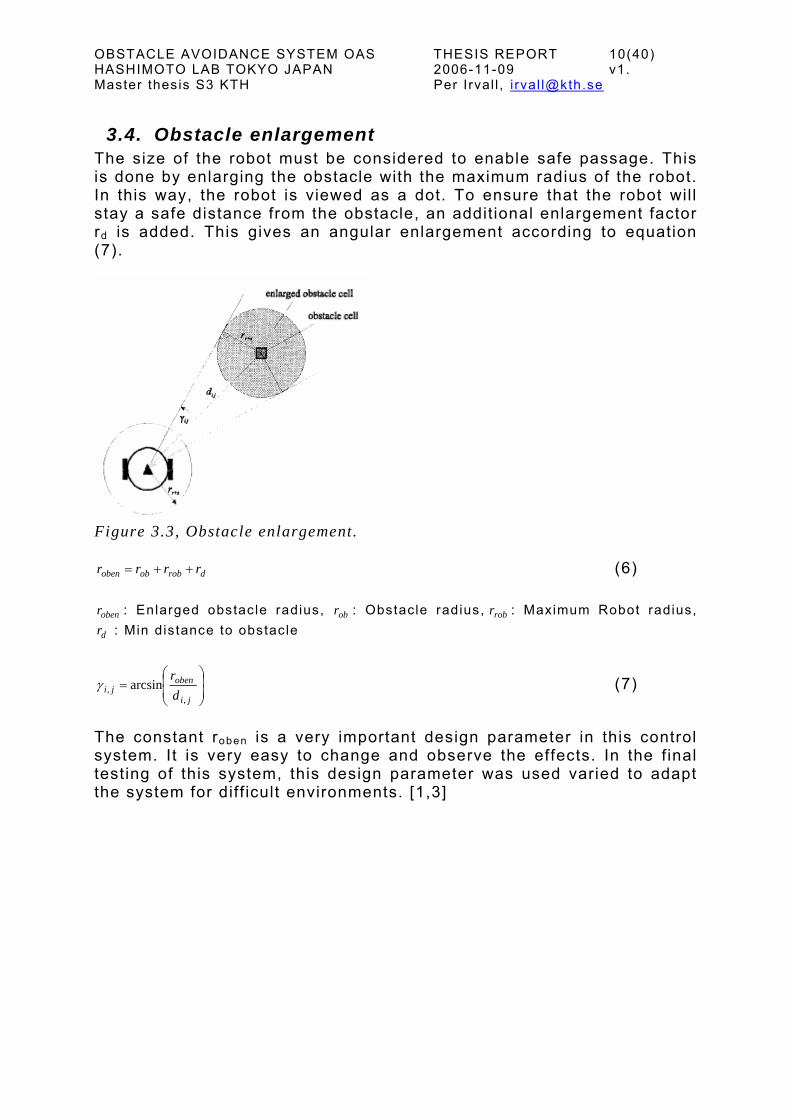
3.4. Obstacle enlargement The size of the robot must be considered to enable safe passage. This is done by enlarging the obstacle with the maximum radius of the robot. In this way, the robot is viewed as a dot. To ensure that the robot wil l stay a safe distance from the obstacle, an addit ional enlargement factor rd is added. This gives an angular enlargement according to equation (7).
Figure 3.3, Obstacle enlargement.
droboboben rrrr ++= (6)
obenr : Enlarged obstacle radius, : Obstacle radius, : Maximum Robot radius, : Min distance to obstacle
obr robr
dr
⎟⎟⎠
⎞⎜⎜⎝
⎛=
ji
obenji d
r
,, arcsinγ (7)
The constant roben is a very important design parameter in this control system. It is very easy to change and observe the effects. In the final testing of this system, this design parameter was used varied to adapt the system for diff icult environments. [1,3]

OBSTACLE AVOIDANCE SYSTEM OAS THESIS REPORT 11(40) HASHIMOTO LAB TOKYO JAPAN 2006-11-09 v1. Master thesis S3 KTH Per Irval l , i rval [email protected]
3.5. Blocking criteria Figure 3.4 i l lustrates the problem approach of the masked VFH. The solid circle in the middle is a differential drive robot. The rectangles on each side of the robot are the wheels. The dashed circle around the robot shows the obstacle enlargement factor, . The obstacles A and B can be seen as black dots and the fi l led grey circle around them is the enlarged obstacle as described above. From the centre of the wheel axle, one solid l ine is drawn in left and right direction. These trajectories are the right and left turning radii, r
obenr
r and r l of the robot.
A
k l 2
B
k l 1
k r 1θ
Figure 3.4, Explanation of the masked VFH. The posit ion of the right and left trajectory centre relative to the current robot posit ion is given by:
θθ
cossin
rr
rr
ryrx
=∆=∆ (8)
θθ
cossin
ll
ll
ryrx
−=∆−=∆
The distance from an active obstacle to the right and left trajectory centre is given by:
( )( ) (( )( )( ) (( 222
222
jyyixxd
jyyixxd
lll
rrr
∆−∆+∆−∆=
∆−∆+∆−∆= )))
(9)

OBSTACLE AVOIDANCE SYSTEM OAS THESIS REPORT 12(40) HASHIMOTO LAB TOKYO JAPAN 2006-11-09 v1. Master thesis S3 KTH Per Irval l , i rval [email protected] On the right side, there is a dashed circle going out from the middle of the robot axles. Let’s call this curvature kr1 . On the left side, two curvatures kl1 and kl2 , have been drawn where kl1 = kr l = Kmax(corresponding to the minimum turning radius). On the right side, the curvature kr1 intersects with the enlarged obstacle, . Hence, kobenr r1
is blocked and all the curvatures that are greater. On the left side, all the curvatures between kl1 and kl2 are free: this is considered an opening of the size of (kl1- kl2). The program wil l step through the radius vectors {rmin rmax} le f t and {rmin rmax}r igh t checking all the curvatures for intersecting obstacles. The obstacle cell blocks the curvature kr =1/ rr on the right side if:
22 )( drobrr rrrd ++< (10)
The obstacle cell blocks the curvature kl =1/ r l on the right side if:
22 )( drobll rrrd ++< (11)

OBSTACLE AVOIDANCE SYSTEM OAS THESIS REPORT 13(40) HASHIMOTO LAB TOKYO JAPAN 2006-11-09 v1. Master thesis S3 KTH Per Irval l , i rval [email protected] If equations (10) and (11) are used, the robot wil l always go on the left side of the obstacle in f igure 3.5 to reach a goal that is behind. This is because equation (10) is true for al l r r greater than the smallest radius that intersects with the obstacle. But if the larger circle in the f igure 3.5 is going to be a possible curvature, the blocking criteria have to be altered. Goal
Figure 3.5, Description of altered Masked VFH Equation (10) and (11) are changed to:
222
222
)())((
)())((
droblldrobl
drobrrdrobr
rrrdrrr
rrrdrrr
++<<+−
++<<+− (12)
Now the curvatures that intersect with the obstacles are the only ones that are blocked. This alteration gives the robot in f igure 3.5 two openings on the right side with possible curvatures l ike the ones described in f igure 3.5. [1,3]

OBSTACLE AVOIDANCE SYSTEM OAS THESIS REPORT 14(40) HASHIMOTO LAB TOKYO JAPAN 2006-11-09 v1. Master thesis S3 KTH Per Irval l , i rval [email protected]
3.6. Binary VFH For each curvature k, the program loops through the active area A and sums the polar magnitudes of the blocking obstacles. The masked histograms for the right and left side are described by:
∑
∑
×=
×=
Ajijikl
Ajijikr
hmH
hmH
,,
,,
(13)
where hi , j = 1 if equation (11) is true: 0 otherwise. Sometimes a polar histogram can cause problems. For example, when two curvatures, one on the right and the other one on the left side of the obstacle, have similar polar magnitude, the direction is indeterminable. This can be seen as an unstable behaviour where the robot cannot decide which side of the obstacle to pass on and constantly changes its direction. To make the path smoother and avoid undesirable behaviour, it might be wise to consider using the binary histogram:
0
1
=
=Bkr
Bkr
H
H i f (14) Hkr
Hkr
HH
ττ
<≥
0
1
=
=Bkl
Bkl
H
H i f (15) Hkl
Hkl
HH
ττ
<≥
where Hτ is a threshold. The two vectors, left and right can only take the value of one or zero. Zero for opening and 1 for no opening, or obstacle. This makes it easier to search through the vectors and it also removes all uncertainties. [1,3]

OBSTACLE AVOIDANCE SYSTEM OAS THESIS REPORT 15(40) HASHIMOTO LAB TOKYO JAPAN 2006-11-09 v1. Master thesis S3 KTH Per Irval l , i rval [email protected]
3.7. Choosing the direction Going through the binary histogram, the algorithm distinguishes small openings from wide ones. For small openings, there is only one possible direction, the middle curvature. For wide openings, there can be two or three matching curvatures. On the left side, on the right side, or the goal curvature if it is in the opening. Here c is used to describe the possible curvatures. Small opening:
2lr
dkk
c−
= (16)
Wide opening:
2maxs
kc rr += towards the right side (17)
2maxs
kc ll −= towards the left side (18)
goalgoal kc = i f (19) [ lrgoal cck ,∈ ]
smax: small-/wide- opening threshold. To decide the best possible direction, a cost function is applied. The cost depends on goal direction, previous direction, and current direction. In this implementation the current direction and the previous selected are the same and therefore only 2 cost terms are used.
),(),()( 21 prevgoal cckccg ∆+∆×= µµ (20) The ∆ function calculates the difference between the two curvature inputs. Hence, the best curvature is the c that minimizes equation (20).[1,3]

OBSTACLE AVOIDANCE SYSTEM OAS THESIS REPORT 16(40) HASHIMOTO LAB TOKYO JAPAN 2006-11-09 v1. Master thesis S3 KTH Per Irval l , i rval [email protected]
4. Implementation This section wil l treat the hardware used in the project, and the implementation of the map and control. The structure and schedule of the program wil l also be i l lustrated.
4.1. Robot For this project the system wil l be tested for the Pioneer DX mobile robot. The DX robot uses differential drive. This means that it has wheels on a steering axle, and one extra Ackerman wheel that is only used for stationary stabil ity. The two main wheels are each powered by a separate engine, allowing the two wheels to independently rotate in the forward or backward directions. This creates a high manoeuvrabil ity. If the two wheel motors are set to the same speed and direction the robot can move forward or backward in a straight l ine. If the motors are set to the same speed but different directions the robot wil l rotate about its centre point. For other sett ings, the robot wil l move in left and right circles, where the size of the circles wil l be decided by the difference of the two motor speeds.
Figure 4.1, The Pioneer DX. The inputs to the robot are forward and rotation speeds (v,θ). A negative input provides the reverse direction. The robot input speed is scaled and the maximum robot speed is 1.6 m/s. The wheel motors are equipped with encoders which wil l be used in the posit ioning. [4]

OBSTACLE AVOIDANCE SYSTEM OAS THESIS REPORT 17(40) HASHIMOTO LAB TOKYO JAPAN 2006-11-09 v1. Master thesis S3 KTH Per Irval l , i rval [email protected]
4.2. Main sensor For the main sensor on the robot, a Digiclops Stereo Vision System camera wil l be used. The camera is manufactured by PGR (Point Grey Research). The sensor system contains 3 cameras mounted in an L shape making it possible to construct a 3D picture of the environment. PGR provides a full-feature SDK (software development kit) called Triclops. With the Triclops SDK, it is possible to extract range values from each pixel in the image with high accuracy. PGR also provides a number of code examples written in C++, of which one was helpful for gett ing started.
Figure 4.2, Digiclops Stereo Vision System camera. The program takes input from the colour Digiclops camera and performs sub-pixel interpolation to create a 16-bit disparity image. The data from the disparity image is then converted in to x-, y- and z- coordinates. (as i l lustrated in Figure 4.3) For every pixel in the image, the range from the camera is now given by the 3D coordinates.
Figure 4.3, Function of Digiclops Stereo Vision System camera. With the Triclops development kit it was possible to create a 3D image of the environment using the coordinate information of the pixels. However, the image has to be simplif ied and cleared of noise if i t is going to be useful in the OAS program.

OBSTACLE AVOIDANCE SYSTEM OAS THESIS REPORT 18(40) HASHIMOTO LAB TOKYO JAPAN 2006-11-09 v1. Master thesis S3 KTH Per Irval l , i rval [email protected]
Figure 4.4, 3D picture of boxes and basketball. Figure 3.4 i l lustrate how the world is seen through the Digiclops camera. Every white dot in the 3D picture to the right is stored as x,y,z coordinates in a point f i le. This f i le is then used to update the map. The Triclops SDK was used together with a test example from Point Grey Research, with only small changes, the program could be used in the OAS system. The changes were mainly to increase the speed of the image processing.
4.3. Robot Server program The robot is equipped with one onboard computer. This computer is necessary to run the robot server program. The robot server is the l ink between the robot and the main program. While the robot is running, the only messages sent through the robot server are motor speed settings and data from the motor encoders. The communication between the robot and the server is done through a serial cable. The connection between the main program and the robot sever is done by wireless network and TCP socket programming. [6,7]

OBSTACLE AVOIDANCE SYSTEM OAS THESIS REPORT 19(40) HASHIMOTO LAB TOKYO JAPAN 2006-11-09 v1. Master thesis S3 KTH Per Irval l , i rval [email protected]
4.4. Positioning For posit ioning, the robot uses one external system. The Hashimoto lab is equipped with an ultrasound sensor system. 96 ultrasound sensors are placed in the roof of the lab creating a 4 * 4 meter observed testing area. The robot carries two ultrasound tags or transmitters located in the front and rear of the robot along its centreline. One tag would be sufficient since the angular direction of the robot is calculated using movement. However, the number of tags posit ively influences the accuracy of the posit ion estimate of the RCP.
Figure 4.5, Figure 4.6, Ultrasound sensors. Ultrasound transmitter tag. The posit ion is calculated by an external posit ioning server in the lab. The posit ioning server receives the information from the tags one at a t ime which makes the posit ioning calculations slow. It takes 200ms for one tag: 400ms for one posit ion (2 tags per robot). This means that the latest robot posit ion is at t imes almost a half second old. This problem is solved through precognit ion. For precognition, a Kalman fi l ter is used. The Kalman fi l ter is taken from an earl ier project at the lab and is not a part of this project. The fi l ter uses the posit ioning from the ultrasound system together with the motor encoders and speed of the robot to estimate the current and next posit ion. Figure 4.5 i l lustrates the posit ioning of the roof sensors. The sensors are installed in 4 sets in the shape of a square, one in each quadrant with origin in the centre. This leaves a cross with fewer sensors where x or y is close to 0. The posit ioning error in this region is rather large, and could cause problems for the system. However, this problem wil l not infl ict much inaccuracy on the system as long as this region is only crossed swift ly and not used as the start posit ion.

OBSTACLE AVOIDANCE SYSTEM OAS THESIS REPORT 20(40) HASHIMOTO LAB TOKYO JAPAN 2006-11-09 v1. Master thesis S3 KTH Per Irval l , i rval [email protected]
4.5. Map To describe the world, a f ixed decomposit ion cell map is used. This means that the world is described by a grid of squares of a particular size. In this implementation, each square is 10 * 10 cm. The principle of the f ixed decomposit ion cell map is i l lustrated in in f igure 4.7. In this map representation, there are only two values for a square: occupied or free. This makes it very easy to store the map information.
Figure 4.7, Fixed decomposition. The map program has three parts. First the local map describes what is in the robot’s sight at the moment and is internal to the robot; the coordinates are therefore related to the robot posit ion and direction angle. Second, the room map is the memory where the information from the local map is saved, and represents the real room coordinates. Finally, the check map is used to control the update f ield, so that only the area that is in sight of the robots camera at the moment is saved. The map information is stored in four matrices: the old room matrix Rold, the new room matrix R, the local matrix L , and the check matrix C. In this implementation, the matrices all are of the size 40 * 40. This gives a room map of the size 4 t imes 4 meters. The relation between the matrix index and the room coordinates is described by f igure 4.9. The pixel coordinates from the camera image are f irst converted to real room coordinates. [5]

OBSTACLE AVOIDANCE SYSTEM OAS THESIS REPORT 21(40) HASHIMOTO LAB TOKYO JAPAN 2006-11-09 v1. Master thesis S3 KTH Per Irval l , i rval [email protected]
00000000000000000000000000000000000000000000000000000000000000000000000000000000000000000000000000000000000000000000000000000000000000000000000000000000000000000000000000000000000000000000000000000000
00000000000000000000110000000000000000001111000000000000000011111100000000000000111111110000000000001111111111000000000011111111000000000000111111000000000000001111000000000000000011000000000000000000
↓↓↓↓↓↓↓↓↓↓
→←↑↑↑↑↑↑↑↑
↑
→→→→→→→→←←←←←←←←← x
y
00000000000000000000000000000000000000000000000000000000000000000000000011000000000011000000110000000000020000001100000000000102000011111100000000000000111111000000000000000000000000000000000000000000
00000000110000000000000000001100000000000000000000000000000000000000000000000000000000000000000000000000000000000000000000000000000000000000000000000000000001110000000000000000011100000000000000000111
↓↓↓↓↓↓↓↓↓↓
→←↑↑↑↑↑↑↑↑
↑
→→→→→→→→←←←←←←←←← x
y
a b Figure 4.8. The matrix a is the Local matrix L (Local map) and b the Check matrix C (Check map). The program divides the x-z plane into squares with a given size, and then each square is represented by an index in the local matrix. To determine if the square is occupied or not, the program goes through all the 3D points from the image looking for the points within the given square. To determine if the point is a part of an obstacle or not, the y-coordinate is compared with the height boundaries of the robot. There is also a f loor constant to separate to pixels of the f loor from an obstacle. A threshold method is then used to determine how many points in a square are required to differentiate it as an obstacle or just noise. In this implementation, two thresholds are used, threshold 1 and 2. The first one is set higher than the second, and is for separating certain obstacles from uncertain (i.e., points that could or could not be obstacles). The second threshold is for separat ing uncertain obstacles from noise. The index in the local matrix can take the values of 0, 1, and 2 which imply no obstacle, obstacle and possible obstacle. The local matrix is the temporal map one image captures, and the information is bounded by the camera sight angle and choice of image depth. This temporal map is the used to update the real map, the memory. The memory uses two matrixes: the new room matrix R and the old room matrix Rold, where the new room matrix is updated after the information from the local matrix is saved. The old room matrix describes the information form the previous image captures. The matrices R and Rold can take values between 0 and 5. A zero in the matrix indicates that the square is empty. Numbers 1 through 5 i l lustrate how many times an obstacle has been spotted in the same square, with an maximum of 5 t imes. A threshold then determines how many times a obstacle should be spotted before classif ied as an obstacle and not noise, that is, it is certain that the particular posit ion contains an obstacle.

OBSTACLE AVOIDANCE SYSTEM OAS THESIS REPORT 22(40) HASHIMOTO LAB TOKYO JAPAN 2006-11-09 v1. Master thesis S3 KTH Per Irval l , i rval [email protected]
i
i
i
ji
, ≤jiR
The check matrix C is also a temporary map since it depends on the robot coordinates. It can take values 0 and 1, 1 for in camera sight and 0 for not in camera sight. A square (i, j) in the new room matrix R is updated in the following way:
1. If =jL
1, =jiC1,
1,, += oldjiji RR
2. If =jL
1, =jiC0,
1,, −= oldjiji RR
3. If =jL
1, =jiC2,
oldjiji RR ,, =
4. If =C
0,
oldjiji RR ,, =
5. 0 ≤
5
Rule number 2 is important and demands further explanation. This rule is constructed to reduce noise integration and makes it possible to deal with temporary obstacles such as humans. For example if a human steps in the way of the robot, the values in the active area represented by the room matrix wil l be increased. When the human moves out of the area sti l l observed by the robot, the active matrix values wil l decrease and the obstacle wil l disappear, so that the robot can continue in the same path.

OBSTACLE AVOIDANCE SYSTEM OAS THESIS REPORT 23(40) HASHIMOTO LAB TOKYO JAPAN 2006-11-09 v1. Master thesis S3 KTH Per Irval l , i rval [email protected]
00000000000000000000000000000000000000000000000000000000000000000000000033000000000011000000550000000000020000005400000000000101000055455300000000000000333553000000000000000000000000000000000000000000
00000000550000000000000000005400000000000000000000000000000000000000000000000000000000000000000000000000000000000000000000000000000000000000000000000000000005550000000000000000055500000000000000000554
↓↓↓↓↓↓↓↓↓↓
→←↑↑↑↑↑↑↑↑
↑
→→→→→→→→←←←←←←←←← x
y
Figure 4.9. Example of new or the old room matrix map. 2 * 2 m. The arrows are not a part of the matrix; they are only used for demonstrating the axes in this figure. Figure 4.9 describes the new matrix map. The centre of the arrows denotes the origin (X=0, Y=0). This means that index 1,1 in the matrix denotes a square with coordinates X=[ -90, -100], Y=[90, 100] cm. On this example matrix map there is one obstacle between -100 < x < -70, 70 < y < 100,(top left corner), and one between 0 < x < 20 , 0 < y < 20,(centre right ). In the third quadrant there is a L shaped obstacle with the boundaries -80 < x < -20, -40< y < -20, and -40 < x < -20 , -70 < y < -40. In the middle of the forth quadrant some noise can be spotted, values of 1 and 2. (In this implementation the threshold is set for 3).

OBSTACLE AVOIDANCE SYSTEM OAS THESIS REPORT 24(40) HASHIMOTO LAB TOKYO JAPAN 2006-11-09 v1. Master thesis S3 KTH Per Irval l , i rval [email protected]
s.
4.6. Control This section i l lustrates the implementation of the control theory described in section 3, and the parameters that were used.
4.6.1. The masked Vector Field Histogram In this implementation, the active area A was set as a square with the centre in the RCP. For most of the tests performed A was set to 6*6 meters. The reason of this sett ing was that the camera sight length of 3 meter should be included in A. In some tests A were set to 2m2. The reason wil l be explained in the results. The robot maneuverabil ity restrict ions Kmax and Kmin were set to 2 and 1/16 respectively. This implies that the turning radius is restricted to rmin = 0.5m and rmax = 16m. Different sett ings of Kmax and Kmin were tested to get the best performance. The tests showed that the system got unstable for rmin < 0.5m and that rmax = 16m was enough to get strait forward movement behaviour. The step size rs tep was set to one half of the side in a map square, 0.05 m. With these parameters the system got a smooth path and at the same time relatively small vectors to store.
4.6.2. Obstacle magnitude For polar magnitude, equation (3) was used since no certainty values were available from the mapping. The constants, a and b, were set to 9 and 1 in this implementation. These imply that only obstacles within a radius of 3 meters wil l have a posit ive value and be considered in the histogram.
4.6.3. Obstacle enlargement The pioneer DX robot has a maximum radius of 26 cm, hence was set to 30 cm. The minimum distance to obstacle was changed according to the obstacle environment. The DX robot has an oval shape, and the max radius is from the RCP to the rear and front. On the sides, the radius is closer to 15 cm. This makes it possible to set low or even negative. In the most demanding tests with narrow openings,
was set to -10, which implies that r
robr
dr
dr
dr oben = 20 cm. For most tests, was set between 0 and 10 cm. The different sett ings are displayed
for each obstacle set in the resultdr

OBSTACLE AVOIDANCE SYSTEM OAS THESIS REPORT 25(40) HASHIMOTO LAB TOKYO JAPAN 2006-11-09 v1. Master thesis S3 KTH Per Irval l , i rval [email protected]
4.6.4. Building the histogram Equation 11 was used to search for blocking obstacles. In the implementation, the binary histogram was used according to equations 13 and 14, and Hτ was set to 3.0. This implies that there must be at least one obstacle within the range of 2.45m according to equation 3 and the parameters set in section 4.6.3.
4.6.5. Choosing the direction In equation 16 and 17, smax was set to 0.25, where k can take the values {1/16, 2 }. Numerous tests with different smax were preformed to get the best system performance. In the cost function described by equation (20), µ1 and µ2 were set to 5 and 4, respectively. This sett ing created a system that reaches the goal fast while moving in a smooth path.
4.6.6. Full histogram There is one special case in the control that has not been discussed yet, and that is what wil l happen in the case of a ful l histogram, when both the right and the left histogram vectors are f i l led with ones. This can occur when the robot gets to close to an obstacle. This wil l result in no possible openings and no possible curvatures. In this case, the number 21 wil l go through the cost function instead of the possible curvatures because every index in the histogram is f i l led with 21 in the start of every control loop. The number 21 is chosen because it wil l result in a cost value greater than for all possible curvatures, and therefore it wil l not interfere when there is a possible curvature. But in this special case 21 is the only output from the control. When a code 21 is sent, the robot server wil l get a special movement command. Several different movements have been tested and are explained in the results.
OBSTACLE AVOIDANCE SYSTEM OAS THESIS REPORT 26(40) HASHIMOTO LAB TOKYO JAPAN 2006-11-09 v1. Master thesis S3 KTH Per Irval l , i rval [email protected]
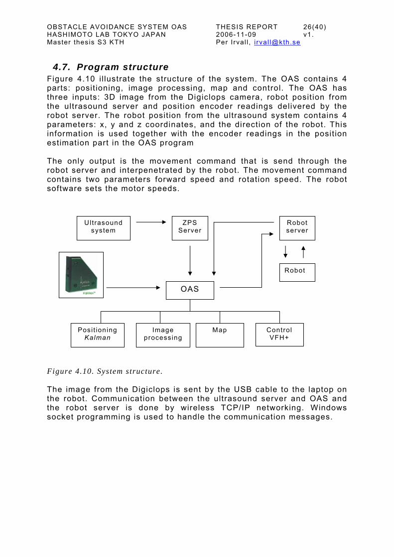
4.7. Program structure Figure 4.10 i l lustrate the structure of the system. The OAS contains 4 parts: posit ioning, image processing, map and control. The OAS has three inputs: 3D image from the Digiclops camera, robot posit ion from the ultrasound server and posit ion encoder readings delivered by the robot server. The robot posit ion from the ultrasound system contains 4 parameters: x, y and z coordinates, and the direction of the robot. This information is used together with the encoder readings in the posit ion estimation part in the OAS program The only output is the movement command that is send through the robot server and interpenetrated by the robot. The movement command contains two parameters forward speed and rotation speed. The robot software sets the motor speeds.
Ul trasound system
ZPS Robot Server server
Robot
OAS
Image processing
Map Posi t ioning Kalman
Control VFH+ Figure 4.10. System structure. The image from the Digiclops is sent by the USB cable to the laptop on the robot. Communication between the ultrasound server and OAS and the robot server is done by wireless TCP/IP networking. Windows socket programming is used to handle the communication messages.

OBSTACLE AVOIDANCE SYSTEM OAS THESIS REPORT 27(40) HASHIMOTO LAB TOKYO JAPAN 2006-11-09 v1. Master thesis S3 KTH Per Irval l , i rval [email protected]
4.8. Program schedule Figure 4.11 describe the program time schedule. A whole schedule loop consists of 4 steps of 200ms. It takes a whole loop of 800ms to get both of the ultrasound tag readings. In every step, prediction is made for the next 3 steps, since the map part that is running in every step needs the current posit ion reading. The control is preformed in every step and uses the map and the robot posit ion.
0 1 2 3 4
R-Tag recv F-Tag recv F-Tag sent R-Tag sent
P r e d i c t M a p C o n t r o l
P r e d i c t M a p C o n t r o l
P r e d i c t M a p C o n t r o l
P r e d i c t M a p C o n t r o l
Wait ing for F-Tag
Wait ing for R-Tag
Time t
2 0 0 m s 2 0 0 m s 2 0 0 m s 2 0 0 m s Figure 4.11, Program schedule.

OBSTACLE AVOIDANCE SYSTEM OAS THESIS REPORT 28(40) HASHIMOTO LAB TOKYO JAPAN 2006-11-09 v1. Master thesis S3 KTH Per Irval l , i rval [email protected]
5. Results To test the overall function of the OAS system, 6 different obstacle environments were set up in the lab, and for each set a number of video and data captures were made. To i l lustrate the captured data which consist of the robot coordinates, a program was constructed in Matlab. This program also demonstrates the obstacle enlargement. The program plots the path of the robot while displaying the obstacles real size with blue squares and the enlarged obstacles by red circles. The robot path is drawn with blue dots and the robot is i l lustrated with a green circle. The goal point can be seen as a red cross, and the start ing posit ion as a red circle with a cross in i t . The program can be used to take single captures of the path or to show the whole set capture as a movie.
OBSTACLE AVOIDANCE SYSTEM OAS THESIS REPORT 29(40) HASHIMOTO LAB TOKYO JAPAN 2006-11-09 v1. Master thesis S3 KTH Per Irval l , i rval [email protected]
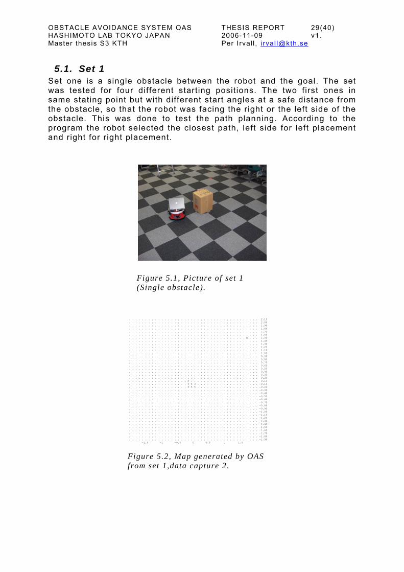
5.1. Set 1 Set one is a single obstacle between the robot and the goal. The set was tested for four different start ing posit ions. The two first ones in same stating point but with different start angles at a safe distance from the obstacle, so that the robot was facing the right or the left side of the obstacle. This was done to test the path planning. According to the program the robot selected the closest path, left side for left placement and right for r ight placement.
Figure 5.1, Picture of set 1 (Single obstacle).
.
.
.
.
.
.
.
.
.
.
.
.
.
.
.
.
.
.
.
.
.
.
.
.
.
.
.
.
.
.
.
.
.
.
.
.
.
.
.
.
Ff
. . . . . . . . . . . . . . . . . . . . . . . . . . . . . . . . . . . . . . . 2.10 . . . . . . . . . . . . . . . . . . . . . . . . . . . . . . . . . . . . . . . 2.00 . . . . . . . . . . . . . . . . . . . . . . . . . . . . . . . . . . . . . . . 1.90 . . . . . . . . . . . . . . . . . . . . . . . . . . . . . . . . . . . . . . . 1.80 . . . . . . . . . . . . . . . . . . . . . . . . . . . . . . . . . . . . . . . 1.70 . . . . . . . . . . . . . . . . . . . . . . . . . . . . . . . . . . . . . . . 1.60 . . . . . . . . . . . . . . . . . . . . . . . . . . . . . . . . . . . R . . . 1.50 . . . . . . . . . . . . . . . . . . . . . . . . . . . . . . . . . . . . . . . 1.40 . . . . . . . . . . . . . . . . . . . . . . . . . . . . . . . . . . . . . . . 1.30 . . . . . . . . . . . . . . . . . . . . . . . . . . . . . . . . . . . . . . . 1.20 . . . . . . . . . . . . . . . . . . . . . . . . . . . . . . . . . . . . . . . 1.10 . . . . . . . . . . . . . . . . . . . . . . . . . . . . . . . . . . . . . . . 1.00 . . . . . . . . . . . . . . . . . . . . . . . . . . . . . . . . . . . . . . . 0.90 . . . . . . . . . . . . . . . . . . . . . . . . . . . . . . . . . . . . . . . 0.80 . . . . . . . . . . . . . . . . . . . . . . . . . . . . . . . . . . . . . . . 0.70 . . . . . . . . . . . . . . . . . . . . . . . . . . . . . . . . . . . . . . . 0.60 . . . . . . . . . . . . . . . . . . . . . . . . . . . . . . . . . . . . . . . 0.50 . . . . . . . . . . . . . . . . . . . . . . . . . . . . . . . . . . . . . . . 0.40 . . . . . . . . . . . . . . . . . . . . . . . . . . . . . . . . . . . . . . . 0.30 . . . . . . . . . . . . . . . . . . . . . . . . . . . . . . . . . . . . . . . 0.20 . . . . . . . . . . . . . . . . . 5 . . . . . . . . . . . . . . . . . . . . . 0.10 . . . . . . . . . . . . . . . . . 5 5 3 . . . . . . . . . . . . . . . . . . . -0.10 . . . . . . . . . . . . . . . . . 5 5 5 . . . . . . . . . . . . . . . . . . . -0.20 . . . . . . . . . . . . . . . . . . . . . . . . . . . . . . . . . . . . . . . -0.30 . . . . . . . . . . . . . . . . . . . . . . . . . . . . . . . . . . . . . . . -0.40 . . . . . . . . . . . . . . . . . . . . . . . . . . . . . . . . . . . . . . . -0.50 . . . . . . . . . . . . . . . . . . . . . . . . . . . . . . . . . . . . . . . -0.60 . . . . . . . . . . . . . . . . . . . . . . . . . . . . . . . . . . . . . . . -0.70 . . . . . . . . . . . . . . . . . . . . . . . . . . . . . . . . . . . . . . . -0.80 . . . . . . . . . . . . . . . . . . . . . . . . . . . . . . . . . . . . . . . -0.90 . . . . . . . . . . . . . . . . . . . . . . . . . . . . . . . . . . . . . . . -1.00 . . . . . . . . . . . . . . . . . . . . . . . . . . . . . . . . . . . . . . . -1.10 . . . . . . . . . . . . . . . . . . . . . . . . . . . . . . . . . . . . . . . -1.20 . . . . . . . . . . . . . . . . . . . . . . . . . . . . . . . . . . . . . . . -1.30 . . . . . . . . . . . . . . . . . . . . . . . . . . . . . . . . . . . . . . . -1.40 . . . . . . . . . . . . . . . . . . . . . . . . . . . . . . . . . . . . . . . -1.50 . . . . . . . . . . . . . . . . . . . . . . . . . . . . . . . . . . . . . . . -1.60 . . . . . . . . . . . . . . . . . . . . . . . . . . . . . . . . . . . . . . . -1.70 . . . . . . . . . . . . . . . . . . . . . . . . . . . . . . . . . . . . . . . -1.80 . . . . . . . . . . . . . . . . . . . . . . . . . . . . . . . . . . . . . . . -1.90 -1.5 -1 -0.5 0 0.5 1 1.5
igure 5.2, Map generated by OAS rom set 1,data capture 2.

OBSTACLE AVOIDANCE SYSTEM OAS THESIS REPORT 30(40) HASHIMOTO LAB TOKYO JAPAN 2006-11-09 v1. Master thesis S3 KTH Per Irval l , i rval [email protected] Figure 5.3 Matlab simulation, Figure 5.4 Matlab simulation, set1,capture 2. set 1, capture 4. roben= 40cm, A = 3m2 roben = 40cm, A = 3m2 For the third and fourth starting posit ion, the robot was placed close behind the obstacle. This is done deliberately to create a situation of no possible openings. In this case, the robot wil l reverse to a safe distance from the obstacle to set a path around it. In the program the whole histogram is covered since all the curvatures are blocked by the enlarged obstacle. For this situation, the program delivers a special command to the robot server. In this experiment the command was set to a straight reverse. The reverse command is given unti l one opening is found in the histogram, since the reverse direction is set to have a higher cost then any of the curvatures. In f igure 5.4 the part were the robot is in reverse is marked with a black arrow. This function is important to get out from dead ends and create more intell igent behaviour.

OBSTACLE AVOIDANCE SYSTEM OAS THESIS REPORT 31(40) HASHIMOTO LAB TOKYO JAPAN 2006-11-09 v1. Master thesis S3 KTH Per Irval l , i rval [email protected]
5.2. Set 2 In set 2, two obstacles are placed close to each other to create a gate between the goal and the robot start posit ion. The gate is only 70 cm wide. Two different staring posit ions are tested for this set. The first at (0,-1.7) is right in front of the opening and the second is at (-1,-1.5), to the left side. For the second start posit ion the angle makes the gate opening seems very small, but the system could sti l l see it and select the passage through the gate instead of going around the whole gate. In the f irst take, the robot was placed right in front of the gate. The opening is small but sti l l considered as a wide opening, since it is bigger than the robot and therefore three curvatures are possible: to the right, to the left, and the goal curvature (see theory). In this test, the robot was able to pick the goal curvature soon after start and fol low it to the goal. This test shows that the system is capable of f inding small openings and picking the most eff icient path to the goal.
Figure 5.5, Picture of set 2 (Two obstacles forming a gate.

OBSTACLE AVOIDANCE SYSTEM OAS THESIS REPORT 32(40) HASHIMOTO LAB TOKYO JAPAN 2006-11-09 v1. Master thesis S3 KTH Per Irval l , i rval [email protected] Figure 5.6 Matlab simulation, Figure 5.7 Matlab simulation, set 2, capture 1 set 2, capture 2 ro b en = 30cm, A = 3m2 ro b en = 20cm, A = 3m2 . . . . . . . . . . . . . . . . . . . . . . . . . . . . . . . . . . . . . . . . 2.10
. . . . . . . . . . . . . . . . . . . . . . . . . . . . . . . . . . . . . . . . 2.00
. . . . . . . . . . . . . . . . . . . . . . . . . . . . . . . . . . . . . . . . 1.90
. . . . . . . . . . . . . . . . . . . . . . . . . . . . . . . . . . . . . . . . 1.80
. . . . . . . . . . . . . . . . . . . . . . . . . . . . . . . . . . . . . . . . 1.70
. . . . . . . . . . . . . . . . . . . . . . . . . . . . . . . . . . . . . . . . 1.60
. . . . . . . . . . . . . . . . . . . . . . . . . R . . . . . . . . . . . . . . 1.50
. . . . . . . . . . . . . . . . . . . . . . . . . . . . . . . . . . . . . . . . 1.40
. . . . . . . . . . . . . . . . . . . . . . . . . . . . . . . . . . . . . . . . 1.30
. . . . . . . . . . . . . . . . . . . . . . . . . . . . . . . . . . . . . . . . 1.20
. . . . . . . . . . . . . . . . . . . . . . . . . . . . . . . . . . . . . . . . 1.10
. . . . . . . . . . . . . . . . . . . . . . . . . . . . . . . . . . . . . . . . 1.00
. . . . . . . . . . . . . . . . . . . . . . . . . . . . . . . . . . . . . . . . 0.90
. . . . . . . . . . . . . . . . . . . . . . . . . . . . . . . . . . . . . . . . 0.80
. . . . . . . . . . . . . . . . . . . . . . . . . . . . . . . . . . . . . . . . 0.70
. . . . . . . . . . . . . . . . . . . . . . . . . . . . . . . . . . . . . . . . 0.60
. . . . . . . . . . . . . . . . . . . . . . . . . . . . . . . . . . . . . . . . 0.50
. . . . . . . . . . . . . . . . . . . . . . . . . . . . . . . . . . . . . . . . 0.40
. . . . . . . . . . . . . . . . . . . . . . . . . . . . . . . . . . . . . . . . 0.30
. . . . . . . . . . . . . . . . . . . . . . . . . . . . . . . . . . . . . . . . 0.20
. . . . . . . . . . . . . . . . . . . . . . . . . 4 . . . . . . . . . . . . . . 0.10
. . . . . . . . . . . . . . . 5 5 . . . . . . . 5 . . . . . . . . . . . . . . . -0.10
. . . . . . . . . . . . . . . 5 4 . . . . . . . 5 4 2 . . . . . . . . . . . . . -0.20
. . . . . . . . . . . . . . . . . . . . . . . . 3 . 1 . . . . . . . . . . . . . -0.30
. . . . . . . . . . . . . . . . . . . . . . . 1 . 5 . . . . . . . . . . . . . . -0.40
. . . . . . . . . . . . . . . . . . . . . . . . . . . . . . . . . . . . . . . . -0.50
. . . . . . . . . . . . . . . . . . . . . . . . . . . . . . . . . . . . . . . . -0.60
. . . . . . . . . . . . . . . . . . . . . . . . . . . . . . . . . . . . . . . . -0.70
. . . . . . . . . . . . . . . . . . . . . . . . . . . . . . . . . . . . . . . . -0.80
. . . . . . . . . . . . . . . . . . . . . . . . . . . . . . . . . . . . . . . . -0.90
. . . . . . . . . . . . . . . . . . . . . . . . . . . . . . . . . . . . . . . . -1.00
. . . . . . . . . . . . . . . . . . . . . . . . . . . . . . . . . . . . . . . . -1.10
. . . . . . . . . . . . . . . . . . . . . . . . . . . . . . . . . . . . . . . . -1.20
. . . . . . . . . . . . . . . . . . . . . . . . . . . . . . . . . . . . . . . . -1.30
. . . . . . . . . . . . . . . . . . . . . . . . . . . . . . . . . . . . . . . . -1.40
. . . . . . . . . . . . . . . . . . . . . . . . . . . . . . . . . . . . . . . . -1.50
. . . . . . . . . . . . . . . . . . . . . . . . . . . . . . . . . . . . . . . . -1.60
. . . . . . . . . . . . . . . . . . . . . . . . . . . . . . . . . . . . . . . . -1.70
. . . . . . . . . . . . . . . . . . . . . . . . . . . . . . . . . . . . . . . . -1.80
. . . . . . . . . . . . . . . . . . . . . . . . . . . . . . . . . . . . . . . . -1.90 -1.5 -1 -0.5 0 0.5 1 1.5
Figure5.8. Map generated by OAS. Set 2, data capture 2.

OBSTACLE AVOIDANCE SYSTEM OAS THESIS REPORT 33(40) HASHIMOTO LAB TOKYO JAPAN 2006-11-09 v1. Master thesis S3 KTH Per Irval l , i rval [email protected]
5.3. Set 3 Set 3 consists of 3 obstacles creating a more demanding path. Again, two starting posit ions were tested. The first one is from behind obstacle 3, and the other one below obstacle 1. The test worked well for both of the start ing points. The reason why it looks l ike the robot hits the obstacle 3 in the Matlab simulation program but not in the movie capture is due to the increased uncertainty of the posit ion close to zero. The ultrasound system has fewer sensors in the origin cross. . . . . . . . . . . . . . . . . . . . . . . . . . . . . . . . . . . . . . . . . 2.10
. . . . . . . . . . . . . . . . . . . . . . . . . . . . . . . . . . . . . . . . 2.00
. . . . . . . . . . . . . . . . . . . . . . . . . . . . . . . . . . . . . . . . 1.90
. . . . . . . . . . . . . . . . . . . . . . . . . . . . . . . . . . . . . . . . 1.80
. . . . . . . . . . . . . . . . . . . . . . . . . . . . . . . . . . . . . . . . 1.70
. . . . . . . . . . . . . . . . . . . . . . . . . . . . . . . . . . . . . . . . 1.60
. . . . . . . . . . . . . . . . . . . . . . . . . . . . . . . . . . . R . . . . 1.50
. . . . . . . . . . . . . . . . . . . . . . . . . . . . . . . . . . . . . . . . 1.40
. . . . . . . . . . . . . . . . . . . . . . . . . . . . . . . . . . . . . . . . 1.30
. . . . . . . . . . . . . . . . . . . . . . . . . . . . . . . . . . . . . . . . 1.20
. . . . . . . . . . . . . . . . . . . . . . . . . . . . . . . . . . . . . . . . 1.10
. . . . . . . . . . . . . . . . . . . . . . . . . . . . . . . . . . . . . . . . 1.00
. . . . . . . . . . . . . . . . . . . . . . . . . . . . . . . . . . . . . . . . 0.90
. . . . . . . . . . . . . . . . . . . . . . . . . . . . . . . . . . . . . . . . 0.80
. . . . . . . . . . . . . . . . . . . . . . . . 4 5 . . . . . . . . . . . . . . 0.70
. . . . . . . . . . 2 5 5 5 . . . . . . . . . . 3 5 . . . . . . . . . . . . . . 0.60
. . . . . . . . . . . 3 5 3 . . . . . . . . . . . 5 5 . 5 . . . . . . . . . . . 0.50
. . . . . . . . . . 1 1 . . . . . . . . . . . . . . 5 5 3 . . . . . . . . . . . 0.40
. . . . . . . . . . . . . . . . . . . . . . . . . . . . . . . . . . . . . . . . 0.30
. . . . . . . . . . . . . . . . . . . . . . . . . . . . . . . . . . . . . . . . 0.20
. . . . . . . . . . . . . . . . . . . . . . . . . . . . . . . . . . . . . . . . 0.10
. . . . . . . . . . . . . . . . . . . . . . . . . . . . . . . . . . . . . . . . -0.10
. . . . . . . . . . . . . . . . . . . . . . . . . . . . . . . . . . . . . . . . -0.20
. . . . . . . . . . . . . . . . . . . . . . . . . . . . . . . . . . . . . . . . -0.30
. . . . . . . . . . . . . . . . . . . . . 5 1 . . . . . . . . . . . . . . . . . -0.40
. . . . . . . . 4 5 5 . . . . . . . . . . 5 2 . . . . . . . . . . . . . . . . . -0.50
. . . . . . . . . . . . . . . . . . . . . 2 . . . . . . . . . . . . . . . . . . -0.60
. . . . . . . . . . . . . . . . . . . . . . . . . . . . . . . . . . . . . . . . -0.70
. . . . . . . . . . . . . . . . . . . . . . . . . . . . . . . . . . . . . . . . -0.80
. . . . . . . . . . . . . . . . . . . . . . . . . . . . . . . . . . . . . . . . -0.90
. . . . . . . . . . . . . . . . . . . . . . . . . . . . . . . . . . . . . . . . -1.00
. . . . . . . . . . . . . . . . . . . . . . . . . . . . . . . . . . . . . . . . -1.10
. . . . . . . . . . . . . . . . . . . . . . . . . . . . . . . . . . . . . . . . -1.20
. . . . . . . . . . . . . . . . . . . . . . . . . . . . . . . . . . . . . . . . -1.30
. . . . . . . . . . . . . . . . . . . . . . . . . . . . . . . . . . . . . . . . -1.40
. . . . . . . . . . . . . . . . . . . . . . . . . . . . . . . . . . . . . . . . -1.50
. . . . . . . . . . . . . . . . . . . . . . . . . . . . . . . . . . . . . . . . -1.60
. . . . . . . . . . . . . . . . . . . . . . . . . . . . . . . . . . . . . . . . -1.70
. . . . . . . . . . . . . . . . . . . . . . . . . . . . . . . . . . . . . . . . -1.80 -1 90
Figure 5.9, Picture of set 3 Figure 5.10, Map generated (Three obstacles ). by OAS. Set 3, data capture 4. Figure 5.11 Matlab simulation Figure 5.12 Matlab simulation Set 3, capture 1 Set 3, capture 4 ro b en = 20cm, A = 3m2 ro b en = 30cm, A = 3m2

OBSTACLE AVOIDANCE SYSTEM OAS THESIS REPORT 34(40) HASHIMOTO LAB TOKYO JAPAN 2006-11-09 v1. Master thesis S3 KTH Per Irval l , i rval [email protected]
5.4. Set 4 In set 4, there a no stationary obstacles between the robot and the goal: instead, the path is disturbed by human interference. Suddenly, a human steps right in front of the robot. For this set, two tests were made. One where the human steps right in front of the robot blocking all curvatures, and the other one where the human interference appears further from the robot. In the first test the histogram is totally blocked and hence the reverse function is tr iggered. The robot reverses unti l a curvature k is free. In the second test, the human obstacle only blocks a part of the histogram, so the route is quickly changed to a larger curvature that is unblocked. This set is made to test how well the system works in human environment with moving objects. . . . . . . . . . . . . . . . . . . . . . . . . . . . . . . . . . . . . . . . . 2.10
. . . . . . . . . . . . . . . . . . . . . . . . . . . . . . . . . . . . . . . . 2.00
. . . . . . . . . . . . . . . . . . . . . . . . . . . . . . . . . . . . . . . . 1.90
. . . . . . . . . . . . . . . . . . . . . . . . . . . . . . . . . . . . . . . . 1.80
. . . . . . . . . . . . . . . . . . . . . . . . . . . . . . . . . . . . . . . . 1.70
. . . . . . . . . . . . . . . . . . . . . . . . . . . . . . . . . . . . . . . . 1.60
. . . . . . . . . . . . . . . . . . . . . . . . . . R . . . . . . . . . . . . . 1.50
. . . . . . . . . . . . . . . . . . . . . . . . . . . . . . . . . . . . . . . . 1.40
. . . . . . . . . . . . . . . . . . . . . . . . . . . . . . . . . . . . . . . . 1.30
. . . . . . . . . . . . . . . . . . . . . . . . . . . . . . . . . . . . . . . . 1.20
. . . . . . . . . . . . . . . . . . . . . . . . . . . . . . . . . . . . . . . . 1.10
. . . . . . . . . . . . . . . . . . . . . . . . . . . . . . . . . . . . . . . . 1.00
. . . . . . . . . . . . . . . . . . . . . . . . . . . . . . . . . . . . . . . . 0.90
. . . . . . . . . . . . . . . . . . . . . . . . . . . . . . . . . . . . . . . . 0.80
. . . . . . . . . . . . . . . . . . . . . . . . . . . . . . . . . . . . . . . . 0.70
. . . . . . . . . . . . . . . . . . . . . . . . . . . . . . . . . . . . . . . . 0.60
. . . . . . . . . . . . . . . . . . . . . . . . . . . . . . . . . . . . . . . . 0.50
. . . . . . . . . . . . . . . . . . . . . . . . . . . . . . . . . . . . . . . . 0.40
. . . . . . . . . . . . . . . . . . . . . . . . . . . . . . . . . . . . . . . . 0.30
. . . . . . . . . . . . . . . . . . . . . . . . 1 . . . . . . . . . . . . . . . 0.20
. . . . . . . . . . . . . . . . . . . . . . 5 5 5 5 . . . . . . . . . . . . . . 0.10
. . . . . . . . . . . . . . . . . . . . . . . . . . . . . . . . . . . . . . . . -0.10
. . . . . . . . . . . . . . . . . . . . . . . . . . . . . . . . . . . . . . . . -0.20
. . . . . . . . . . . . . . . . . . . . . . . . . . . . . . . . . . . . . . . . -0.30
. . . . . . . . . . . . . . . . . . . . . . . . . . . . . . . . . . . . . . . . -0.40
. . . . . . . . . . . . . . . . . . . . . . . . . . . . . . . . . . . . . . . . -0.50
. . . . . . . . . . . . . . . . . . . . . . . . . . . . . . . . . . . . . . . . -0.60
. . . . . . . . . . . . . . . . . . . . . . . . . . . . . . . . . . . . . . . . -0.70
. . . . . . . . . . . . . . . . . . . . . . . . . . . . . . . . . . . . . . . . -0.80
. . . . . . . . . . . . . . . . . . . . . . . . . . . . . . . . . . . . . . . . -0.90
. . . . . . . . . . . . . . . . . . . . . . . . . . . . . . . . . . . . . . . . -1.00
. . . . . . . . . . . . . . . . . . . . . . . . . . . . . . . . . . . . . . . . -1.10
. . . . . . . . . . . . . . . . . . . . . . . . . . . . . . . . . . . . . . . . -1.20
. . . . . . . . . . . . . . . . . . . . . . . . . . . . . . . . . . . . . . . . -1.30
. . . . . . . . . . . . . . . . . . . . . . . . . . . . . . . . . . . . . . . . -1.40
. . . . . . . . . . . . . . . . . . . . . . . . . . . . . . . . . . . . . . . . -1.50
. . . . . . . . . . . . . . . . . . . . . . . . . . . . . . . . . . . . . . . . -1.60
. . . . . . . . . . . . . . . . . . . . . . . . . . . . . . . . . . . . . . . . -1.70
. . . . . . . . . . . . . . . . . . . . . . . . . . . . . . . . . . . . . . . . -1.80
. . . . . . . . . . . . . . . . . . . . . . . . . . . . . . . . . . . . . . -1.5 -1 -0.5 0 0.5 1 1.5
. . -1.90
Figure 5.13, Picture of set 4 Figure 5.14, Map generated (Mobile obstacle “human”). by OAS. Set 4, data capture 2. Figure 5.15 Matlab simulation, Figure 5.16 Matlab simulation, Set 4, capture 2 Set 4, capture 3 ro b en = 40cm, A = 3m2 ro b en = 30cm, A = 3m2

OBSTACLE AVOIDANCE SYSTEM OAS THESIS REPORT 35(40) HASHIMOTO LAB TOKYO JAPAN 2006-11-09 v1. Master thesis S3 KTH Per Irval l , i rval [email protected]
5.5. Set 5 Set 5 is a corridor with a right angle bend. This set is tr icky since the angle of the stereo camera is very l imited, only 60 degrees. This restriction makes the corridor turn look l ike a dead end for the robot. To cope with this situation, the active area was change to 1 meter instead of 3 (see theory). With the active are only 1 m2 the wall A is invisible for the control part but sti l l registered in the map. This makes the robot go further into the corridor and f ind the turn opening. To make the system even better the reverse function can be change to a turning movement to be able to f ind the way in narrow corridors. In this set, two tests were made, the f irst one with active area 3m and the second with 1m. In the f irst, the corridor was treated l ike a dead end and the robot reversed and went around the corridor accessing the goal from the other side. In the second test, the robot went further and could f ind the opening. . . . . . . . . . . . . . . . . . . . . . . . . . . . . . . . . . . . . . . . . 2.10
. . . . 2 5 5 5 3 2 5 2 2 5 5 5 5 5 5 4 5 . . . . . . . . . . . . . . . . . . . 2.00
. . . . 1 5 4 3 3 4 . . . . . . . . . . . . . . . . . . . . . . . . . . . . . . 1.90
. . . . 1 2 . . . . . . . . . . . . . . . . . . . . . . . . . . . . . . . . . . 1.80
. . . . . 5 . . . . . . . . . . . . . . . . . . . . . . . . . . . . . . . . . . 1.70
. . . . . 5 . . . . . . . . . . . . . . . . . . . . . . . . . . . . . . . . . . 1.60
. . . . . 5 . . . . . . . . . . . . . . . . . . . . R . . . . . . . . . . . . . 1.50
. . . . . 5 5 . . . . . . . . . . . . . . . . . . . . . . . . . . . . . . . . . 1.40
. . . . 3 5 3 . . . . . . . . . . . . . . . . . . . . . . . . . . . . . . . . . 1.30
. . . . . 4 1 . . . . . . . . . . . . . . . . . . . . . . . . . . . . . . . . . 1.20
. . . . 2 5 3 . . . . . . . . . . . . . . . . . . . . . . . . . . . . . . . . . 1.10
. . . . . 2 . . . . . . . . . . . . . . . . . . . . . . . . . . . . . . . . . . 1.00
. . . . 1 3 . . . . . . . . 1 5 . . . . . . . . . . . . . . . . . . . . . . . . 0.90
. . . 5 5 2 . . . . . . . . . 5 . . . . . . . . . . . . . . . . . . . . . . . . 0.80
. . . . . . . . . . . . . . . 5 . . . . . . . . . . . . . . . . . . . . . . . . 0.70
. . . . . . . . . . . . . . . 5 . . . . . . . . . . . . . . . . . . . . . . . . 0.60
. . . . . . . . . . . . . . . 5 . . . . . . . . . . . . . . . . . . . . . . . . 0.50
. . . . . . . . . . . . . . . 5 . . . . . . . . . . . . . . . . . . . . . . . . 0.40
. . . . 5 5 . . . . . . . . . 5 . . . . . . . . . . . . . . . . . . . . . . . . 0.30
. . . . 5 5 . . . . . . . . 2 . . . . . . . . . . . . . . . . . . . . . . . . . 0.20
. . . . 4 5 . . . . . . . . . 5 . . . . . . . . . . . . . . . . . . . . . . . . 0.10
. . . 5 5 5 . . . . . . . . . . . . . . . . . . . . . . . . . . . . . . . . . . -0.10
. . . 5 5 5 . . . . . . . . . . . . . . . . . . . . . . . . . . . . . . . . . . -0.20
. . . . . . . . . . . . . . . . . . . . . . . . . . . . . . . . . . . . . . . . -0.30
. . . . . . . . . . . . . . . . . . . . . . . . . . . . . . . . . . . . . . . . -0.40
. . . . . . . . . . . . . . . . . . . . . . . . . . . . . . . . . . . . . . . . -0.50
. . . . . . . . . . . . . . . . . . . . . . . . . . . . . . . . . . . . . . . . -0.60
. . . . . . . . . . . . . . . . . . . . . . . . . . . . . . . . . . . . . . . . -0.70
. . . . . . . . . . . . . . . . . . . . . . . . . . . . . . . . . . . . . . . . -0.80
. . . . . . . . . . . . . . . . . . . . . . . . . . . . . . . . . . . . . . . . -0.90
. . . . . . . . . . . . . . . . . . . . . . . . . . . . . . . . . . . . . . . . -1.00
. . . . . . . . . . . . . . . . . . . . . . . . . . . . . . . . . . . . . . . . -1.10
. . . . . . . . . . . . . . . . . . . . . . . . . . . . . . . . . . 1 . . . . . -1.20
. . . . . . . . . . . . . . . . . . . . . . . . . . . . . . . . 1 . . . . . . . -1.30
. . . . . . . . . . . . . . . . . . . . . . . . . . . . . . . . 3 . . . . . . . -1.40
. . . . . . . . . . . . . . . . . . . . . . . . . . . . . . . . . . . . . . . . -1.50
. . . . . . . . . . . . . . . . . . . . . . . . . . . . . . . . . . . . . . . . -1.60
. . . . . . . . . . . . . . . . . . . . . . . . . . . . . . . . . . . . . . . . -1.70
. . . . . . . . . . . . . . . . . . . . . . . . . . . . . . . . . . . . . . . . -1.80
. . . . . . . . . . . . . . . . . . . . . . . . . . . . . . . . . . . . . . . . -1.90 -1.5 -1 -0.5 0 0.5 1 1.5
Figure 5.17, Picture of set 5 Figure 5.18, Map generated (“corridor”). by OAS. Set 5, data capture 2.

OBSTACLE AVOIDANCE SYSTEM OAS THESIS REPORT 36(40) HASHIMOTO LAB TOKYO JAPAN 2006-11-09 v1. Master thesis S3 KTH Per Irval l , i rval [email protected] Figure 5.19 Matlab simulation of Figure 5.20 Matlab simulation Set ,5 capture 1 of Set 5, capture 2 ro b en = 20cm, A = 3m2 ro b en = 30cm, A = 1m2

OBSTACLE AVOIDANCE SYSTEM OAS THESIS REPORT 37(40) HASHIMOTO LAB TOKYO JAPAN 2006-11-09 v1. Master thesis S3 KTH Per Irval l , i rval [email protected]
5.6. Set 6 Set 6 is the most demanding set build l ike a maze where the robot starts in the middle and the goal is outside. The lab space didn’t al low a bigger maze but the principle is the same. In this set just l ike the corridor, A was set to 1m2, but this was not enough get out. The maze is t ight and the robot doesn’t have much room to navigate. In previous tests the speed was set to reverse when the robot gets to close to one obstacle (in case of no openings). In this set, the reverse command would result in a coll ision with obstacles behind the robot. Instead, the command was changed to stationary rotation. To make the system more eff icient, the rotation direction was set to turn in the same direction as the goal curve. If the goal curvature is negative (right side) the command wil l be right rotation, and left rotation for posit ive goal curvature. In the picture, the f irst turn wil l be to the right and the second one to the left in the situation of full histogram.
Figure 5.21, Picture of set 6 (“Maze”)
. . . . . . . . . . . . . . . . . . . . . . . . . . . . . . . . . . . . . . . . 2.10
. . . . . . . . . . . . . . . . . . . . . . . . . . . . . . . . . . . . . . . . 2.00
. . . . . . . . . . . . . . . . . . . . . . . . . . . . . . . . . . . . . . . . 1.90
. . . . . . . . . . . . . . . . . . . . . . . . . . . . . . . . . . . . . . . . 1.80
. . . . . . . . . . . . . . . . . . . . . . . . . . . . . . . . . . . . . . . . 1.70
. . . . . . . . . . . . . . . . . . . . . . . . . . . . . . . . . . . . . . . . 1.60
. . . . . . . . . . . . . 2 5 5 5 5 3 5 4 . . . . . . . . . . . . . . . . . . . 1.50
. 5 5 5 5 5 5 5 5 5 1 3 5 5 5 5 5 5 5 5 5 . . . . . . . . . . . . . . . . . . . 1.40
. . . . 1 . . . . 3 5 . . . . . . . . 2 1 . . . . . . . . . . . . . . . . . . . 1.30
. . . . . . . . . . . . . . . . . . . 5 4 . . . . . . . . . . . . . . . . . . . 1.20
. . . . . . . . . . . . . . . . . . . 2 5 . . . . . . . . . . . . . . . . . . . 1.10
. . . . . . . . . . . . . . . . . . . . 5 . . . . . . . . . . . . . . . . . . . 1.00
. 5 . . . . . . . . . . . . . . . . . . 5 . . . . . . . . . . . . . . . . . . . 0.90
. 5 . . . . . . . . . . . . . . . . . . 5 . . . . . . . . . . . . . . . . . . . 0.80
. 1 . . . . . . . . . . . . . . . . . . 5 . . . . . . . . . . . . 2 . . . . . . 0.70
. 5 . . . . . . . . . . . . . . . . . . 5 . . . . . . . 2 . . . . . 2 . . . . . 0.60
. 3 . . . . . . . . . . . . . . . . . . 5 . . . . . . . . . . . . . 2 . . . . . 0.50
. 5 . . . . . . . . . . . . . . . . . . 5 . . . . . . . . . . . . . . . . . . . 0.40
. 5 . . . . . . . . . . . . . . . . . . . . . . . . . . . . . . . . 4 . . . . . 0.30
. 5 . . . . . . . . . . . . . . . . . . . . . . . . . . . . . . . . . . . . . . 0.20
. . . . . . . . . . . . . . . . . . . . . . . . . . . . . . . . . . . . . . . . 0.10
. . . . . . . . . . . . 4 . . . . . . . . . . . . . . . . . . . . . . . . . . . -0.10
. . . . . . . . . . . . . . . . . . . . . . . . . . . . . . . . . . . . . . . . -0.20
. . . . . . . . . . . . 5 . . . . . . . . . . . . . . . . . . . . . . . . . . . -0.30
. . . . . . . . . . . 1 5 . . . . . . . . . . . . . . . . . . . . . . . . . . . -0.40
. . . . . . . . . . . 2 5 . . . . . . . . . . . . . . . . . . . . . . . . . . . -0.50
. . . . . . . . . . . . 5 . . . . . . . . . . . . . . . . . R . . . . . . . . . -0.60
. . . . . . . . . . . . 5 . . . . . . . . . . . . . . . . . . . . . . . . . . . -0.70
. . . . . . . . . . . . 5 . . . . . . . . . . . . . . . . . . . . . . . . 5 5 . -0.80
. . . . . . . . . . . . 5 2 . . . . . . . . . . . . . . . . . . . . . . . 5 5 . -0.90
. . . . . . . . . . . . 5 . . . . . . . . . . . . . . . . . . . . . . . . . . . -1.00
. . . . . . . . . . . . 2 5 5 5 5 5 5 5 . . . . . . . . . . . . . . . . . . . . -1.10
. . . . . . . . . . . . . . . . . . . . . . . . . . . . . . . . . . . . . . . . -1.20
. . . . . . . . . . . . . . . . . . . . . . . . . . . . . . . . . 1 . . . . . . -1.30
. . . . . . . . . . . . . . . . . . . . . . . . . . . . . . . . 2 1 . . . . . . -1.40
. . . . . . . . . . . . . . . . . . . . . . . . . . . . . . . 2 2 . . . . . . . -1.50
. . . . . . . . . . . . . . . . . . . . . . . . . . . . . . . 4 . . . . . . . . -1.60 3 1 1 70
Figure 5.22 Matlab simulation of Figure 5.23, Map generated Set 6, capture 4 from set 6, data capture 2. roben = 20cm, A = 1m2

OBSTACLE AVOIDANCE SYSTEM OAS THESIS REPORT 38(40) HASHIMOTO LAB TOKYO JAPAN 2006-11-09 v1. Master thesis S3 KTH Per Irval l , i rval [email protected]
6. Conclusions The tests show that the OAS system performs well in many different situations. The map building was constructed with success and tested with minimal noise. The robot control is easy to adjust through design parameters, and the behaviour can be optimised for different tasks or environments. However, this implementation is done in a controlled lab environment and not in the real world. With other sensor equipment the system could be improved to work outside the lab. The posit ion system should be replaced by, for example ground GPS which is more accurate, portable and easier to implement for large areas. The vision sensors should be expanded. The Digiclops 3D camera is a very powerful sensor, but the angle is only 60 degrees. It should be expanded to 360 degrees. In the lab environments, the l ightning is always the same and the variation of colours in the environment is l imited. In the real world with constantly changing l ighting, shades, and mult iple colours, the noise factor can be expected to increase. The system was tested successfully for human interference, and with 360 degrees of expanded vision, it could work properly in a crowded place such as an airport or train station. The OAS code is now a part of the Hashimoto lab:s database, and can be used of any of the members in the lab. One of the research projects currently preformed at the lab is a program that using hand movements to give orders in the intell igent space. One of the ideas is to use the program to control the robot for doing off ice delivery service. The robot is called with a wave and can be sent away with a folder of paper to another off ice member. The OAS can be used as control system to navigate the robot in the off ice environment.

OBSTACLE AVOIDANCE SYSTEM OAS THESIS REPORT 39(40) HASHIMOTO LAB TOKYO JAPAN 2006-11-09 v1. Master thesis S3 KTH Per Irval l , i rval [email protected]
7. Bibliography [1] Borenstein, J Koren, Y.,”The Vector Field Histogram – Fast
Obstacle Avoidance for Mobile Robots. “ IEEE Journal of Robotics and Automation , 7,278,288, 1991.
[2] J.-H. Lee, H. Hashimoto, “Intell igent Space – concept and
contents”, /Advanced Robotics/, Vol.16, No.3, pp.265-280, 2002. [3] Ulrich.I, Borenstein, J.,”VFH+:Reliable Obstacle Avoidance
for fast Mobile Robots”.Proceedings of the 1998 “IEEE international Conference on Rootics & Automation” . Leuven,Belgium,May 1998.
[4] Pioneer 2/Peoplebot Operat ions manual v9, Pioneer 2-DX,
2001 ActivMedia robotics LLC. [5] Movarec,h.AND Elfes,A.E.,”high Resolutoin Maps from Wide
Angle Sonar,” in Proceedings of the 1985 IEEE International Conference on Robotics and Automation , IEEE Press,At.-Louis,MO,March 1985,pp.116-121.
7.1 Internet sources [6] TCP server http://www.codeproject.com/internet/winsockintro01.asp
[7] TCP client http://www.codeproject.com/internet/winsockintro02.asp

OBSTACLE AVOIDANCE SYSTEM OAS THESIS REPORT 40(40) HASHIMOTO LAB TOKYO JAPAN 2006-11-09 v1. Master thesis S3 KTH Per Irval l , i rval [email protected]
8. Appendix
• Appendix A Project plan
