observations of severe abutment backwall...
TRANSCRIPT
TRANSPORTATION RESEARCH RECORD 1319 SS
Observations of Severe Abutment Backwall Damage
RAY w. JAMES, HEPING ZHANG, AND DAN G. ZOLLINGER
Field stu?ies of highway bridge performance have led to repeated observations of severe cracking and dislocation of the backwalls of reinforced-concrete abutments. The observed distress is correlated with the presence of adjacent reinforced-concrete pavements, and the cause is attributed to the longitudinal growth of t~e concrete ~a~ements. Field observations are presented and discussed. A fmtte element model of a representative abutment is used to study the expected stress distributions caused by several hypothesized mechanisms that might contribute to the observed damage. Methods to prevent future damage are discussed.
A field study of the performance of bridge decks, approach slabs, and adjacent pavement surfaces as a part of a study of bridge approach roughness led to numerous observations of severe cracking and often displaced ruptures in abutment backwalls. In extreme cases, the backwall is broken off the abutment and displaced away from the embarkment toward the bridge, usually resting against the adjacent girder ends or bridge deck. The field study included surveys of approximately 117 bridges , and was accomplished with the intention of quantifying the bridge approach roughness. The survey sites were not selected randomly; district engineers in 5 of Texas's 24 districts were first requested to identify sites with a history of required approach roadway maintenance to maintain ride quality . From the responses, a set of 34 bridges was selected for initial inspection and study. In a later phase of the study, a second, randomly selected set of approximately 83 bridges was also examined. Only observations relating to abutment damage are discussed.
DESCRIPTION OF THE OBSERVED BACKWALL DAMAGE
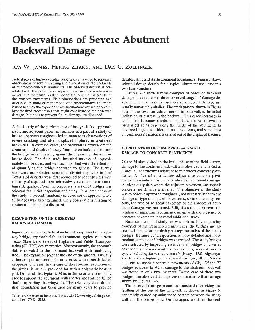
Figure 1 shows a longitudinal section of a representative highway bridge, approach slab, and abutment, typical of current Texas State Department of Highways and Public Transportation (SDHPT) design practice. Most commonly, the approach slab is doweled to the abutment backwall with reinforcing steel. The expansion joint at the end of the girders is usually either an open armored joint or is sealed with a prefabricated neoprene joint seal. In the case of short beams , expansion of the girders is usually provided for with a polymeric bearing pad. Drilled shafts, typically 30 in. in diameter, are commonly used to support the abutment, with shorter and smaller drilled shafts supporting the wingwalls. This relatively deep-drilled shaft foundation has been used for many years to provide
i:-exas Transportation Institute, Texas A&M University, College Stallon, Tex. 77843-3135.
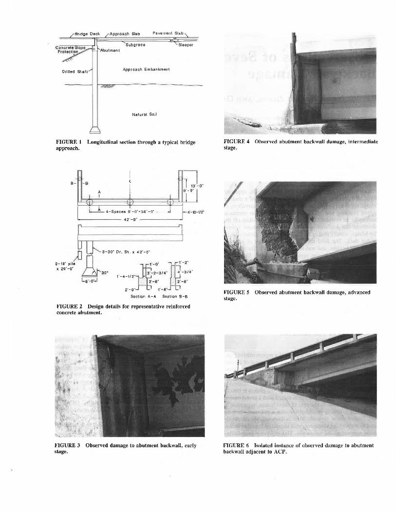
durable, stiff, and stable abutment foundations. Figure 2 shows selected design details for a typical abutment used under a two-lane structure .
Figures 3-5 show several examples of observed backwall damage, and represent three observed stages of damage development. The various instances of observed damage are usually remarkably similar. The crack pattern shown in Figure 3, from the lower outside corner of the backwall , is the initial indication of distress in the backwall. This crack increases in length and becomes displaced, until the entire backwall is broken off at its base along the length of the abutment. In advanced stages, considerable spalling occurs , and sometimes embankment fill material is carried out of the displaced fracture.
CORRELATION OF OBSERVED BACKWALL DAMAGE TO CONCRETE PAVEMENTS
Of the 34 sites visited in the initial phase of the field survey, damage to the abutment backwall was observed and noted at 9 sites, all at structures adjacent to reinforced-concrete pavements. At five other structures adjacent to concrete pavements, no mention was made of observed abutment damage. At eight study sites where the adjacent pavement was asphalt concrete, no damage was noted. The objective of the study was to observe approach roughness, not necessarily abutment damage or type of adjacent pavements, so in some early records, the type of adjacent pavement or the absence of abutment damage was not noted . Still, the strong apparent correlation of significant abutment damage with the presence of concrete pavements motivated additional study.
Because the initial study set was obtained by requesting examples of maintenance-intensive sites, the bridges and associated damage are probably not representative of the state's bridges. Because of this question, a more detailed and more random sample of 83 bridges was surveyed. The study bridges were selected by inspecting essentially all bridges on a series of randomly chosen circuitous routes on highways of various types, including farm roads, state highways, U.S. highways, and Interstate highways. Of these 83 bridges, all but 6 were adjacent to asphalt concrete pavements (ACP). Of the 77 bridges adjacent to ACP, damage to the abutment backwall was noted in only two instances. In the case of these two bridges, the observed damage was not similar to that damage shown by Figures 3-5.
The observed damage in one case consisted of cracking and spalling of the t?p of t~e wingwall , as shown in Figure 6, apparently causea by umntended contact between the wingwall and the bridge deck. On the opposite side of the deck
Approach Slab Pavement Slab
Subgrade Sleeper
Drilled Shalt Approach Embankment
Natural Soil
FIGURE 1 Longitudinal section through a typical bridge approach.
t ·.~ 8- - 8
I 1 13' - 0'
A y 9· 1 I i I
.. ~. / '• , ' I I •
r- ~·- 10-v2· ~ 4-Spaces 9'-0"•36'-0"----1
42'-9'
6 J )J u:::,.,,. ''· "'· . .,._,. . .
.. -:~~:!· n ,,. . ~· 3·1~~~·3 ,4·m· -f:/4" & 1 -4-1/2" ' ' Ls·-o,_i .. · 2·-s· :-: 2·-s·
2·-9· 1· - a·
Section A-A Section 8-8
FIGURE 2 Design details for representative reinforced concrete abutment.
FIGURE 3 Observed damage to abutment backwall, early stage.
_,
FIGURE 4 Observed abutment backwall damage, intermediate stage.
I
FIGURE 5 Observed abutment backwall damage, advanced stage.
FIGURE 6 Isolated instance of observed damage to abutment backwall adjacent to ACP.

James et al.
at that abutment, a similar unintended contact pressure has caused cracking and spalling of the edge of the bridge deck. The cause of the bridge or embankment movement resulting in this unintended contact is not known. It may be deduced only that either the embankment is moving toward the bridge, carrying the abutment, or the bridge superstructure is moving toward the embankment. Localized pressure by soil or pavement against the top of the backwall is expected to cause backwall damage before the backwall contacts the girder ends. In the second instance of damage to a backwall at a site adjacent to ACP, the observed damage is generally similar to the first instance, as shown in Figure 7. It is not as clear in this case that the damage is caused by bearing pressure between the wingwall and the deck, as in Figure 6, but a close inspection of the abutment reveals that the damage in this instance is isolated in the wingwaU, with the backwall undamaged.
Finally, a third example of distress in a bridge abutment adjacent to ACP was observed in the initial field study. The observed distress in this example took the form of an apparently displaced approach slab , as shown in Figure 8. However , the cause of this displacement is the gross rotation of the abutment as shown in Figure 9. The embankment at this site is underlain by soft soils, and the rotation is attributed to
FIGURE 7 Observed damage to abutment wingwall at structure adjacent to ACP: Case 2.
FIGURE 8 Approach slab apparently displaced relative to back wall.
57
FIGURE 9 Rotated abutment and wingwall.
differential settlement. Other evidence of differential settlement is also noted at this site. The mechanism causing the observed distress is therefore different than the mechanism observed at the sites adjacent to reinforced-concrete pavements . No damage was sustained by the backwall in this instance, even though the backwall has been displaced approximately 2 in. toward the approach slab. Design drawings for this structure indicate that the approach slab is not dowelled to the abutment backwall, as is commonly done in other similar structures. Because of this, the relative displacement of backwall and approach slab is not restrained and does not cause distress .
The six bridges at sites adjacent to reinforced concrete pavements were all on the same section of highway, and of these six, three exhibited significant abutment backwall distress , essentially identical to that shown in Figures 3-5. In summary, three of six abutments next to continuous reinforcedconcrete pavements (CRCP) were damaged, whereas none of the 77 bridges next to ACP exhibited similar damage .
OTHER OBSERVATIONS IMPLICATING LONGITUDINAL GROWTH OF CONCRETE PAVEMENTS
In addition to the broken backwalls, other observations indicate longitudinal growth of the CRCP. At some sites where
58
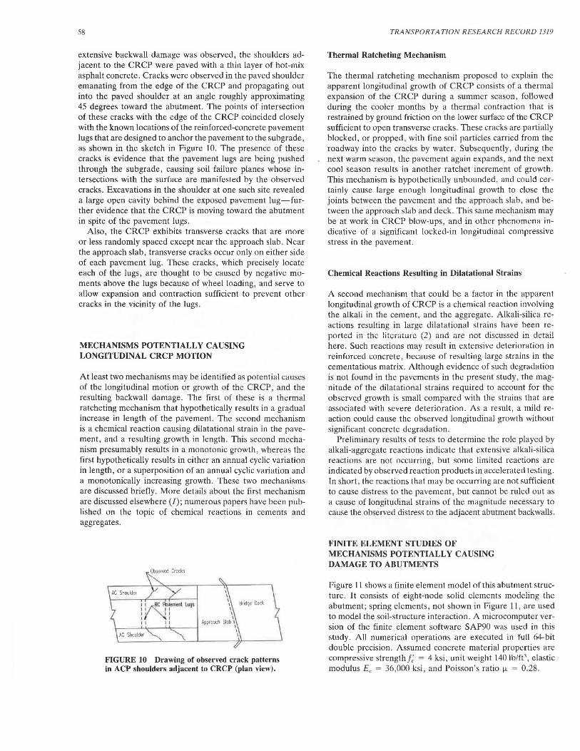
extensive backwall damage was observed, the shoulders adjacent to the CRCP were paved with a thin layer of hot-mix asphalt concrete. Cracks were observed in the paved shoulder emanating from the edge of the CRCP and propagating out into the paved shoulder at an angle roughly approximating 45 degrees toward the abutment. The points of intersection of these cracks with the edge of the CRCP coincided closely with the known locations of the reinforced-concrete pavement lugs that are designed to anchor the pavement to the subgrade, as shown in the sketch in Figure 10. The presence of these cracks is evidence that the pavement lugs are being pushed through the subgrade, causing soil failure planes whose intersections with the surface are manifested by the observed cracks. Excavations in the shoulder at one such site revealed a large open cavity behind the exposed pavement lug-further evidence that the CRCP is moving toward the abutment in spite of the pavement lugs.
Also, the CRCP exhibits transverse cracks that are more or less randomly spaced except near the approach slab. Near the approach slab, transverse cracks occur only on either side of each pavement lug. These cracks, which precisely locate each of the lugs, are thought to be caused by negative moments above the lugs because of wheel loading, and serve to allow expansion and contraction sufficient to prevent other cracks in the vicinity of the lugs.
MECHANISMS POTENTIALLY CAUSING LONGITUDINAL CRCP MOTION
At least two mechanisms may be identified as potential causes of the longitudinal motion or growth of the CRCP, and the resulting backwall damage. The first of these is a thermal ratcheting mechanism that hypothetically results in a gradual increase in length of the pavement. The second mechanism is a chemical reaction causing dilatational strain in the pavement, and a resulting growth in length. This second mechanism presumably results in a monotonic growth, whereas the first hypothetically results in either an annual cyclic variation in length, or a superposition of an annual cyclic variation and a monotonically increasing growth. These two mechanisms are discussed briefly. More details about the first mechanism are discussed elsewhere (J); numerous papers have been published on the topic of chemical reactions in cements and aggregates.
FIGURE IO Drawing of observed crack patterns in ACP shoulders adjacent to CRCP (plan view).
TRANSPORTATION RESEARCH RECORD 1319
Thermal Ratcheting Mechanism
The thermal ratcheting mechanism proposed to explain the apparent longitudinal growth of CRCP consists of a thermal expansion of the CRCP during a summer season, followed during the cooler months by a thermal contraction that is restrained by ground friction on the lower surface of the CRCP sufficient to open transverse cracks. These cracks are partially blocked, or propped, with fine soil particles carried from the roadway into the cracks by water. Subsequently, during the next warm season, the pavement again expands, and the next cool season results in another ratchet increment of growth. This mechanism is hypothetically unbounded, and could certainly cause large enough longitudinal growth to close the joints between the pavement and the approach slab, and between the approach slab and deck. This same mechanism may be at work in CRCP blow-ups, and in other phenomem1 indicative of a significant locked-in longitudinal compressive stress in the pavement.
Chemical Reactions Resulting in Dilatational Strains
A second mechanism that could be a factor in the apparent longitudinal growth of CRCP is a chemical reaction involving the alkali in the cement, and the aggregate. Alkali-silica reactions resulting in large dilatational strains have been reported in the literature (2) and are not discussed in detail here. Such reactions may result in extensive deterioration in reinforced concrete, because of resulting large strains in the cementatious matrix. Although evidence of such degradation is not found in the pavements in the present study, the magnitude of the dilatational strains required to account for the observed growth is small compared with the strains that are associated with severe deterioration. As a result, a mild reaction could cause the observed longitudinal growth without significant concrete degradation.
Preliminary results of tests to determine the role played by alkali-aggregate reactions indicate that extensive alkali-silica reactions are not occurring, but some limited reactions are indicated by observed reaction products in accelerated testing. In short, the reactions that may be occurring are not sufficient to cause distress to the pavement, but cannot be ruled out as a cause of longitudinal strains of the magnitude necessary to cause the observed distress to the adjacent abutment backwalls.
FINITE ELEMENT STUDIES OF MECHANISMS POTENTIALLY CAUSING DAMAGE TO ABUTMENTS
Figure 11 shows a finite element model of this abutment structure. It consists of eight-node solid elements modeling the abutment; spring elements, not shown in Figure 11, are used to model the soil-structure interaction. A microcomputer version of the finite element software SAP90 was used in this study. All numerical operations are executed in full 64-bit double precision. Assumed concrete material properties are compressive strength/; = 4 ksi, unit weight 140 lb/ft3
, elastic modulus Ee = 36,000 ksi, and Poisson's ratio µ = 0.28.

James et al. 59
z
SAP90
FIGURE 11 Finite element model of bridge abutment.
The soil-structure interaction was simplified by employing a Winkler soil model, as shown in Figure 12. The soil surrounding the shaft is represented by a set of elastic springs. Winkler's assumption states that each spring acts independently. Although this assumption does not exactly describe the soil behavior, it has been demonstrated that solutions of beam-on-foundation problems using Winkler's assumption do not differ appreciably from solutions assuming the soil to be an isotropic, elastic continuum. It is convenient to think of Winkler's model in terms of P-Y curves, also shown in Figure 12. The soil modulus E, is then taken to be PIY. Because the P- Y relationship is usually nonlinear , the modulus E, is not constant, but it may be linearly approximated for small deflections. A linear approximation was used in this study. Terzaghi (3) suggested the following formula for stiff clays:
(1)
where
kh = coefficient of horizontal subgrade reaction, ks1 = basic value of coefficient of vertical subgrade reac
tion , and b = width of pile or drilled shaft.
z a) ldealizotion or soil surrounding a shofl b) Set of p-y curves
FIGURE 12 Representation of Winkler soil model and P-Y curves.
Then, the soil modulus Es = PIY is given by
(2)
The soil strength data obtained from borings at the site modeled is presented in Table 1. The embankment is approximately 20 to 30 ft deep and consists mainly of clay and sandy clay. Dry densities are approximately 100 lb/ft3
.
Assuming that the coefficient of subgrade reaction does not depend on depth yields the values for k,1 presented in Table 2.
The soils surrounding the abutment are modeled as two layers , one representing the embankment fill , and one :epresenting natural undisturbed soil. The Es values used m the model are presented in Table 3. These values were calculated on the basis of the data in Table 1, assuming the average q" for fill is 1. 5 tons/ft2 and for natural soil is 2 tons/ft2, and assuming q" is about 3 to 5 tons/ft2 at 42-ft depth. The spring constants for the Winkler springs are obtained from these values for E,.
The soil 's response to the dynamic loads is known to be significantly different from the response to long-term static
TABLE 1 MEASURED VALUES OF SOIL ULTIMATE STRENGTH, q"
Derth (fl)
11 13 15 17 19 21 23 25 27 29 31
Soil Uhimale Strength q, (lons/fl1)
Boring No.
1.25 4 1.5 1.5 0.75, 1.75 1.5 LS 2.0 2.0 2,0 2.0 2.5 1.5 1.5 1.0. 2.5 1.5 1.5 2.25 2.25 1.5 2.25 1.5 2.5 2.25
3 3A
2.0 2.5 0.75
1.5 2.0, 3.0 2.75 2.0 2.75 1.75 1.75 1.75 2.0 1.75 2.25 1.75 2.5 1.75 3.0 1.75, 4 + 4+ 4+ 1.5
2.0 1.0 1.0, 2.0 35 3.5 2.25 1.5 2.5 2.0 2.0 3.0 4+ 2.75

60
TABLE 2 VALUES OF k,1 FOR CALCULATING VALUES OF CLAY SOIL MODULUS E,
Selected k,1
Consistency q" ( tons/ft2) k,, (tons/ft') (tons/ft')
Stiff 1-2 50-100 75 Very stiff 2-4 100-200 150 Hard >4 >200 300
TABLE 3 VALUES OF E, USED IN MODEL
Subgrade Filled Layer ( tons/ft2) Natural Layer (tons/ft2)
Horizontal Vertical
50 75
100 150-300
loads. To model this, the E, values used for the live load were taken to be twice the values used for static loads. The properties of the soil springs were determined and the finite element model was constructed using these E, values.
FINITE ELEMENT ANALYSIS
Using the finite element model described earlier, the following loading cases were simulated:
Case 1. Longitudinal Pavement Growth. The end of the approach slab and the top of abutment backwall are assumed to be constrained to move together, so that the abutment backwall is displaced 1 in. toward the bridge deck.
Case 2. Settlement I. The load capacity of one 30-in.diameter drill shaft on the right side is assumed to be reduced 50 percent (a) dead load only; and {b) live load only (one HS20 truck).
Case 3. Settlement II. Two wingwall piles are assumed to lose all tip resistance.
Case 4. Soil pressure. Soil pressure of 1 kip/ft2 is assumed to be uniformly distributed on the inside surfaces of the abutment.
Case 5. Live load only (one HS20 truck). Case 6. Dead load only. Case 7. Sensitivity to the soil-structure interaction model
when (a) E, is assumed to be increased 100 percent for Case 1, {b) E, is assumed to be increased 100 percent for Case 6, and (c) E, is assumed to be decreased 50 percent for Case 6.
Some simulation results for load Case 1 are presented in Figure 13. In load Case 1, the approach slab is forcing the abutment backwall 1.0 in. forward, and the resulting force between approach slab and abutment backwall is approximately 228 kips. The wingwall is predicted to rotate approximately 0.37 degree. The abutment vertical settlement is about 0.35 in. The anticipated damage for this load case is cracking of the backwall or backwall-wingwall intersection, consistent with the observed damage in the field. Similar results from other load cases are not presented here. Cases 2 and 5 results indicate highest stress concentrations in the top center of the backwall, and in Cases 3 and 4, highest stresses occur at the ends of the backwall. Dead-load stresses in Case 6 are small, as are live-load stresses in Case 5. Accordingly, it may be
TRANSPORTATION RESEARCH RECORD 1319
z y .._J_,R x
FIGURE 13 Predicted deformed shape for load Case I.
concluded that the mechanisms modeled in Cases 1, 3, and 4 each acting separately or together could be contributing factors to the damage observed. Because of the other observations implicating pavement growth, and because of the low probability of loss of support under the wingwall piles or the development of high lateral earth pressures on the abutment walls, Case 1 loading is considered the most likely explanation of the observed damage.
METHODS TO MITIGATE OR ELIMINATE FUTURE DAMAGE TO ABUTMENTS
The reinforced-concrete pavement lugs are intended to anchor the ends of the CRCP. It is apparent that in certain situations, these lugs are not performing their intended function. Two obvious means of mitigating the observed damage are to provide an anchor system that functions reliably or to isolate the CRCP from the approach slab. Strengthening of the abutment backwall sufficiently to resist the thermal expansion of the CRCP is not practical, although it is evident that some redesign of the reinforcement details in the abutment design may be justifiable. The most straightforward way to eliminate future damage to abutments is to provide an isolation, or pressure relief, joint between the end of the CRCP and the approach slab. An isolation joint consisting of a 36-in. gap filled with ACP has been used in other states. Although the presence of such a joint may increase maintenance by requiring periodic planning or grinding, the increased life of the abutments will easily offset small increase in maintenance costs. Other methods to isolate the abutment from the approach slab may also prove practical. Mechanical expansion joints have been proposed and studied. Omitting the dowelled connection between the approach slab and abutment backwall prevents damage to the backwall, but may be undesirable for other reasons.
SUMMARY AND CONCLUSIONS
Field observations of severe damage to abutment backwalls, supported by numerical stress analysis, lead to the conclusion

James et al.
that the observed damage is caused by longitudinal growth of CRCP, causing longitudinal pressures on the abutment backwalls. Pressure relief joints have not been used at the sites where damage was observed, and are recommended as retrofit solutions at sites where damage has occurred and for prevention at sites where damage has not yet occurred. Whether the longitudinal pavement growth may be attributed to a chemical reaction in the concrete or to a thermal ratcheting mechanism has not yet been determined. This question is still being studied.
Second, it may be concluded that the reinforced-concrete pavement lugs are failing to completely anchor the end of the CRCP, at least at sites where this damage has been observed. A review of the design method for sizing these lugs should be performed as well as a review of several of the failures, to determine whether an improved design method for anchor lugs is warranted.
ACKNOWLEDGMENTS
Much of the work described here was funded by the Texas SDHPT and the FHWA, for which support the authors are appreciative.
61
REFERENCES
1. R. W. James, H. Zhang, D. G. Zollinger, L. J. Thompson, R . F. Bruner, and D. Xin. A Study of Bridge Approach Roughness. Research Report 1213-lF. Texas Transportation Institute, Texas A&M University, College Station, 1990, 113 pp.
2. R. L. Carasquillo and P. G. Snow. Effect of Fly Ash on AlkaliAggregate Reaction in Concrete. ACI Materials Journal, Vol. 84, No. 4, American Concrete Institute, Detroit, Mich., July-Aug. 1987, pp. 299-305.
3. K. Terzhagi. Evaluation of Coefficients of Subgrade Reaction. Geotechnique-The International Journal of Soil Mechanics, Vol. 5, No. 4, Institute of Civil Engineers, London, 1955, pp. 297-326.
The contents of this report reflect the views of the authors, who are responsible for the facts and accuracy of the data presented herein. The contents do not necessarily reflect the official views or policies of the FHWA or the Texas State Department of Highways and Public Transportation . This report does not constitute a standard, specification, or regulation.
Publication of this paper sponsored by Cammi/lee on General Structures.