objectives 1. describe various level ratings that apply to telecommunication cables and jacks and...
TRANSCRIPT


OBJECTIVESOBJECTIVES
1. Describe various level ratings that apply to telecommunication cables and jacks and identify where each is implemented.2. Describe the various levels of the cabling category rating systems.3. Define terms associated with category performance.4. State the proper type of wiring system for a given network application.5. Given a certain network type, state the maximum transmission speed and
distance the network can handle.

Table 4-1: Rating Levels

Table 4-2: Cabling Category Ratings

Table 4-3: CAT5 Maximum Attenuation Ratings

Table 4-4: Minimum NEXT Ratings

Figure 4-1: Hierarchical Token Ring

A station can only transmit when it has the token.
All transmitted frames are passed from station to station around the ring.
All stations test each passing frame for messages addressed to them, process the information if it is theirs, and pass a marked token back around the ring.
The original transmitting station releases the token when it returns around the loop.
Token Ring transmission operates like this:
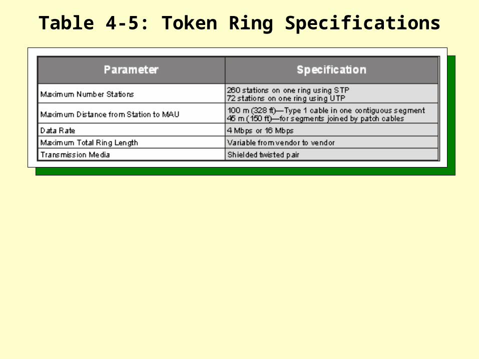
Table 4-5: Token Ring Specifications

LAB 8 OBJECTIVELAB 8 OBJECTIVEInstalling UDC Connectors on 150-Ohm STP
To understand how to install UDC To understand how to install UDC connectors on 150-ohm STP cableconnectors on 150-ohm STP cable

You should take special note of the various connector and cable types specified, as well as their configurations.
TIPTIP

a
Figure 4-2: Threading the UDC Strain Relief and Dust Cover

Remember to trim the four wires to 5/8 of an inch, as indicated in the instruction sheet. While following the instructions, keep in mind that you are using Type-1A cable.
TIPTIP

Figure 4-3: Removing the UDC Lock
Notice that once the lock is removed, the UDC release tabs on either side of the adapter are free to flex.
TIPTIP

Figure 4-4: Connecting the UDC and Adapter Together

Figure 4-5: Reinstalling the UDC Lock

Figure 4-6: Testing the
Cable Assembly

If everything is working properly, the cable tester should indicate that lines 1 through 6 are connected, while lines 7 and 8 are not. If your tester indicates a short between lines 3 and 6, this is normal because both lines are grounded.
TIPTIP

If you hold a tube down with your thumb, you can use a slotted-head screwdriver to pry its wire up and out without inflicting any damage on the tube itself.
TIPTIP

Figure 4-7: Removing the Wires

LAB 8 QUESTIONSLAB 8 QUESTIONS
How many signal wires are supplied with 150-ohm, Type-1A STP cable?
11

LAB 8 QUESTIONSLAB 8 QUESTIONS
Which pins are grounded in a UDC/RJ45 adapter?
22

LAB 8 QUESTIONSLAB 8 QUESTIONS
Is it possible to disconnect the UDC/RJ45 adapter from a UDP connector without first removing the UDC lock?
33

Figure 4-8: Transmission Pairs of a 100baseT4, 8-pin Modular Plug

It operates on virtually any preexisting twisted pair cabling.
The advantages of using 100baseT4 include:
Its adapters are about 10% less expensive than those for other systems.
Less expensive CAT3 cabling can be used.
It cannot support Full Duplex mode (unneeded in workstations).
The disadvantages of using 100baseT4 include:
It requires four pairs of wiring to operate.
It uses only two pairs of twisted pair wiring.
The advantages of using 100baseTX include:
It supports Full Duplex mode for up to 200 Mbps in network servers.

All of the patch panels and jumper blocks must be CAT5-compatible.
The disadvantages of using 100baseTX include:
Adjacent cable pairs cannot be used for other applications.
Distance limitation per link is 100 meters, or 200 meters with a single repeater.
Full duplex mode requires Full Duplex switching apparatus.

Straightforward migration to higher performance levels without disruption
Several key considerations for choosing a Gigabit Ethernet high-speed network include:
Low cost of ownership—including both purchase and support
Capability to support new applications and data types
Network design flexibility

Using existing 4-pair, CAT5 cable that conforms to TIA/EIA T568A
Digital communications techniques include:
Using all four pairs in the cable to keep symbol rate at, or below, 125 Mbaud
Using PAM5 coding to increase the amount of information sent per symbol
Using 4D 8-state Trellis Forward Error Correction to limit noise and crosstalk
Using pulse shaping to condition the transmitted spectrum
Using DSP equalization for noise, echo, crosstalk, and BER compliance

Some ATM Technology key applications include:
Video conferencing
Desktop conferencing
Multimedia communications
ATM over satellite communications
Mobile computing over ATM for wireless networks

Figure 4-9: BNC T Connector

LAB 9 OBJECTIVELAB 9 OBJECTIVEPlacing a BNC Connector on a Coaxial Cable
To understand how to place a To understand how to place a BNC connector on a coaxial BNC connector on a coaxial cablecable

Figure 4-10: Coaxial Components

You will first use the 6-inch piece of RG58 cable, or a piece from the scrap heap, for practice purposes before working on the 5-meter section.
TIPTIP

Figure 4-11: Setting the Cable Stripper for RG58

The V-block insert will slide out if you push it from the back side, using the Allen wrench stored in the bottom of the stripper, so that you can rotate it to the correct setting before reinserting.
TIPTIP

Table 4-6: V-Block Settings

Again, use the Allen wrench to push the large center pin out just as you did with the V-block insert. Cup the top in your hand as the pin is removed to prevent it from jumping off the assembly. Set the center pin safely aside.
TIPTIP
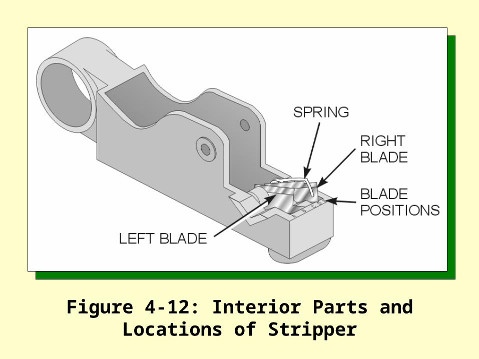
Figure 4-12: Interior Parts and Locations of Stripper

The blades may need to be adjusted somewhat for stripping RG58 cable. The blade positions A and B are intended to adjust the position of the blade that strips to the inner conductor of the cable. Blade positions C, D, and E are intended to adjust the position of the blade that strips to the braid (or alternately, to the center insulation through the braid).
TIPTIP

Table 4-7: Cable Stripper Settings

Figure 4-13: Removing Small Center Pin

Figure 4-14: Positioning the Cutting Blades

The dimensions refer to the distance between a stripped center conductor and an intact cable jacket. Take care to keep the spring oriented properly once the blades have been positioned.
TIPTIP

This all sounds easy enough, but the blades need to be aligned perfectly before the small center pin will reinsert correctly. If you need help, see your instructor.
TIPTIP
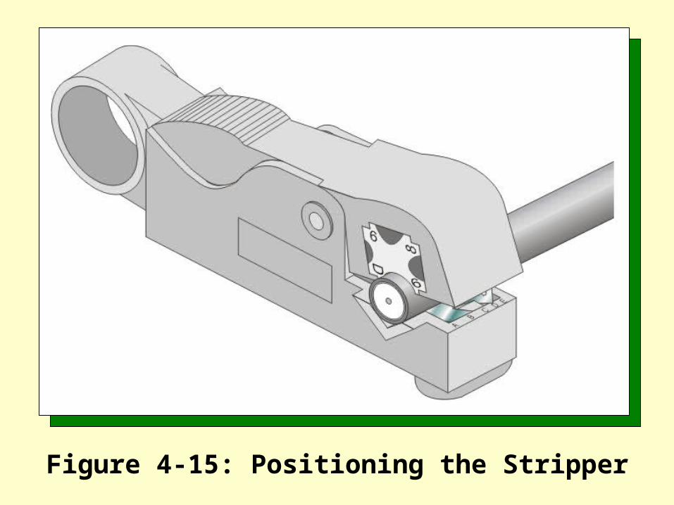
Figure 4-15: Positioning the Stripper

Figure 4-16: Adjusting the Depth of the Blades
Keep in mind that the blade on the left strips to the center conductor, while the blade on the right strips to the braid, or alternately, through the braid to the center insulation. In this case, you’ll want to strip through the braid to the center insulator. When trying to perfect the depth of cuts provided by the stripper, you should use the 6-inch piece you cut from the spool (or a piece of RG58 from the scrap heap), and practice adjusting the blade heights so that neither the center conductor nor the insulation is damaged by the cut. Obviously, a two-bladed stripper will require you to perform additional work to trim the braid properly.
TIPTIP

Do not rotate the stripper too many times with thin RG58 cable, because the friction between the center conductor and insulation may serve to twist the center conductor off, or the continuous spring tension on the blade may cause it to cut too deeply with extra rotations.
TIPTIP

Table 4-8: Cutting Measurements

All of the cuts must be sharp and square. Do not nick the braid, the dielectric, or the center conductor. Use the tension scale/tape measure to check the measurements.
TIPTIP

Figure 4-17: Strip Dimensions

Figure 4-18: BNC Components

Figure 4-19: BNC Installation

Be sure to orient the ferrule so that the flared end is facing toward the cable end that you are currently preparing.
TIPTIP

As you slide the contact pin on, you should check its inspection hole to verify that the center conductor is visible.
TIPTIP

Figure 4-20: Crimping the Contact Pin
As you slide the main body onto the cable, the heel of the main body should slide between the braiding and the dielectric. If you are using a snap-type connector, you will feel the snap as you push the main body and contact pin together.
TIPTIP
A
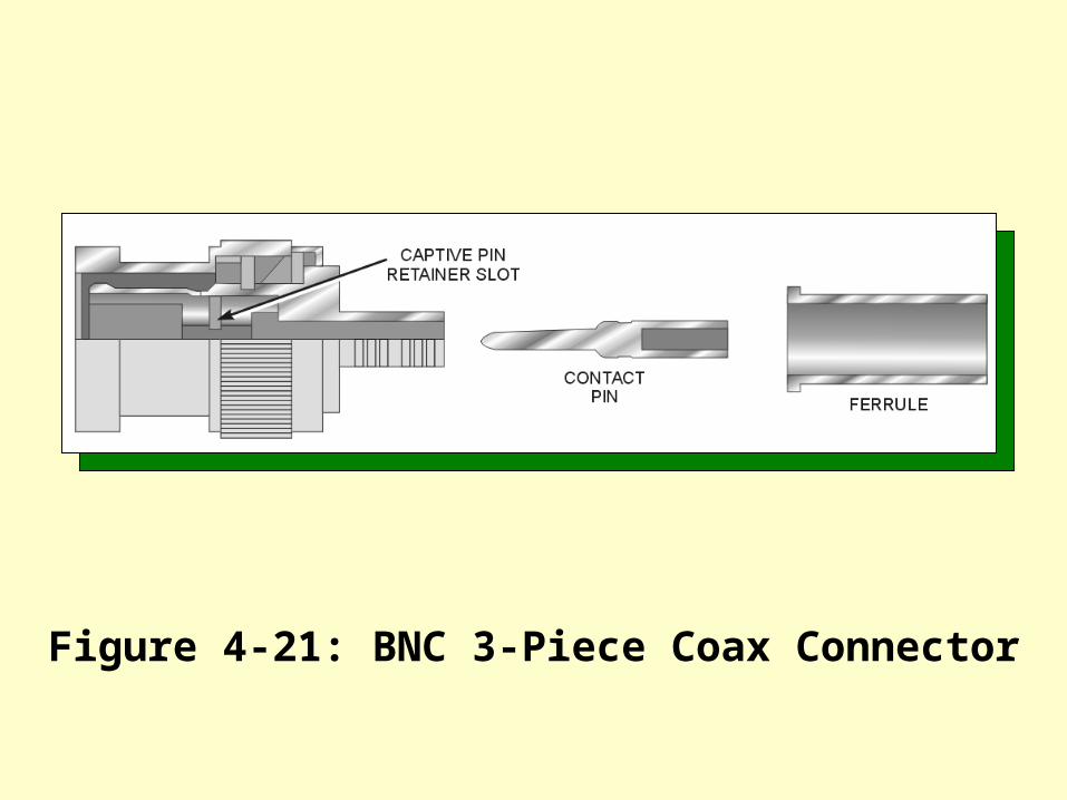
Figure 4-21: BNC 3-Piece Coax Connector

If you are using a twist-on connector, the main thing to remember is to make sure that no braid is touching the center conductor.
TIPTIP

Figure 4-22: BNC Twist-On Connector

Figure 4-23: Crimping the Sleeve

The multimeter should show an infinite resistance between the center conductor and the grounded main bodies of the RG58 connectors. If it does not, the cable is not correctly prepared, and you may have to repeat this procedure. If the cable checks out good, continue with the remaining steps.
TIPTIP
Recall that taps can be used on backbone cables in order to add nodes to an existing network. These taps provide two-way communications just as if the tap line were an original part of the network.
TIPTIP

LAB 9 QUESTIONSLAB 9 QUESTIONS
What will happen if the braid is touching the center conductor after the installation?
11

LAB 9 QUESTIONSLAB 9 QUESTIONS
Why must all of the cuts to the braid, dielectric, and center conductor be accomplished without nicks?
22

LAB 9 QUESTIONSLAB 9 QUESTIONS
What should the resistance be between the center conductor and the braid shield in a RG58 coaxial cable?
33

LAB 9 QUESTIONSLAB 9 QUESTIONS
What happens when the cable stripper is rotated too many times?
44

LAB 9 QUESTIONSLAB 9 QUESTIONS
Where is the Allen wrench stored?55
LAB 10 OBJECTIVELAB 10 OBJECTIVEInstalling F Connectors on a Coaxial Cable
To understand how to install To understand how to install an F connector on an RG6, an F connector on an RG6, 75-ohm coaxial cable75-ohm coaxial cable

You should first use the 6-inch piece of RG6 cable, or a piece from the scrap heap, for practice purposes before working on the 5-meter section.
TIPTIP

Figure 4-24: Setting the Cable Stripper for RG6
Slide the V-block insert out by pushing it from the backside with the hex wrench stored in the bottom of the stripper, rotate it to the correct setting, and then reinsert. RG6 cable is the same type that is used for cable TV transmission in the home, and the F connector is the same type that connects to the back of your television set.
TIPTIP

The locations of the blades for RG6 cable will be the same as for RG58. However, the depth of the blades will have to be altered, because RG6 is a larger diameter cable than RG58.
TIPTIP

Remember that the dimensions refer to the distance between a stripped center conductor and an intact cable jacket. The spring needs to be oriented properly once the blades have been positioned.
TIPTIP

The small center pin will reinsert correctly only if the blades are perfectly aligned. This is not always as easy to accomplish as it sounds. If you need help, see your instructor.
TIPTIP

Again, the blade on the left strips to the center conductor, while the blade on the right strips to the braid, or alternately, through the braid to the center insulation. In this case, you’ll want to strip down through the braid, to the foil shield just below it. Use the 6-inch piece you cut from the spool (or a piece of RG6 from the scrap heap) to practice adjusting the blade heights so that neither the center conductor nor the foil shield is damaged by the cut.
TIPTIP

Even though RG6 cable is thicker than RG58, do not rotate the stripper too many times or damage will occur to either the center conductor or the foil shield. All of the cuts are to be sharp and square. Do not nick the foil shield, the dielectric, or the center conductor. You do not want any of the braid showing along the foil shield.
TIPTIP

Figure 4-25: Properly Stripped RG6

Figure 4-26: Mounting an F Connector

This sounds much easier than it happens to be. The main problem occurs when trying to fit the inside collar of the F connector between the foil shield and the outer jacket of the cable. You have to overcome the resistance of the braid shield just below the jacket.
TIPTIP

Figure 4-27: Pushing RG6 Cable into an F Connector

If it does not, you will have to pull the connector, cut the end from the cable, and repeat the stripping procedure so as to meet this requirement. Before doing so, check the settings on the stripper to be sure that the dimension setting is BC, and allow a short length of cable to protrude beyond the front edge of the stripper, rather than placing it flush. This should give you more than 1/8 of an inch of protrusion for the center conductor from the F connector.
TIPTIP

Figure 4-28: Crimping an F Connector

Once you begin to make the crimp in the F connector, something may cause you to want to stop before the crimping has completed (wire not positioned properly, etc.). If this happens, you can cause the crimping tool to release the connector by pushing up on the release lever between its handles.
TIPTIP

The 1/8-inch buffer will ensure that the nut on the F connector turns freely once the crimp has been completed. This is important because F connectors are attached by screwing the male nut onto a threaded female barrel.
TIPTIP

Figure 4-29: Checking for an Open Circuit

The multimeter should show an infinite resistance between the center conductor and the grounded main bodies of the RG6 connectors. If it does not, the cable is not correctly prepared, and you may have to repeat this procedure. If the cable checks out good, continue with the remaining steps.
TIPTIP

LAB 10 QUESTIONSLAB 10 QUESTIONS
Why should the nut on a crimped F connector be free to spin?
11

LAB 10 QUESTIONSLAB 10 QUESTIONS
How can you interrupt the crimping tool before a crimp has been completed?
22

LAB 10 QUESTIONSLAB 10 QUESTIONS
What should the resistance be between the center conductors on each end of the RG6 coaxial cable?
33

LAB 10 QUESTIONSLAB 10 QUESTIONS
When crimping an F connector, how much uncrimped distance should be allowed between the edge of the crimper and the edge of the connector’s crimp barrel?
44

LAB 10 QUESTIONSLAB 10 QUESTIONS
Where does the collar on the rear of the F connector fit when a properly stripped RG6 cable is pushed into it?
55

LAB 11 OBJECTIVELAB 11 OBJECTIVEInstalling N Connectors on a Coaxial Cable
To understand how to install To understand how to install an N connector on a RG8, an N connector on a RG8, 50-ohm coaxial cable50-ohm coaxial cable

The 5-meter piece should be cut using the 2.5 meter markings on the cable. This will result in a marker at either end, and a marker in the middle. If there is an odd length left over, use this for the shorter piece.
TIPTIP

As with previous procedures, you should first use the 12-inch piece of RG8 cable, or a piece from the scrap heap, for practice purposes before working on the 5-meter section.
TIPTIP

Figure 4-30: Retracting the RG8 Stripping Blade

Notice that the stripper slides apart slightly, retracting the blade far enough to allow the insertion of a RG8 cable for stripping.
TIPTIP

Figure 4-31: Inserting RG8 into the Cable Stripper

Figure 4-32: Stripping RG8

Even though the required cuts have been made, you may find that the insulation is difficult to remove from the center conductor. If this is the case, use the pliers to get a good grip on the cut portion of the insulation before rotating it loose.
TIPTIP

The friction that exists between the jacket and the braided shielding is larger than that of the other cable types you have been using, even though the stripper may have made a good cut around the jacket. If the jacket still refuses to slide, the utility knife may be needed to cut a slit in the outer jacket lengthwise. Then the jacket can simply be peeled off from the cable.
TIPTIP

Figure 4-33: Threading N Connector Components

Professional installations require that the contact be soldered to the 12 AWG center conductor. If soldering equipment is not available, the pin crimper tool (10-14 slot) can alternately be used to make an emergency connection.
TIPTIP

You do not need to tighten the nut with all your strength. Firm is tight enough! Once you have an N connector installed on one end of the cable (or any type of cable where soldering is used), it’s a good idea to test it before working on the other end of the cable. It will make it easier to troubleshoot the cable knowing that one end has already checked out good.
TIPTIP

Do this for both the center conductor at both ends and the connector bodies or braided/foil shielding at both ends. In both cases, the meter should indicate a short.
TIPTIP

You do not need to tighten the nut with all your strength! Firm is tight enough! Once you have an N connector installed on one end of the cable (or any type of cable where soldering is used), it’s a good idea to test it before working on the other end of the cable. It will make it easier to troubleshoot the cable knowing that one end has already checked out good.
TIPTIP

Do this for both the center conductor at both ends and the connector bodies or braided/foil shielding at both ends. In both cases, the meter should indicate a short.
TIPTIP

zzzz
Figure 4-34: Checking for an Open Circuit

LAB 11 QUESTIONSLAB 11 QUESTIONS
Why should the center pin on an N connector be soldered rather than crimped?
11

LAB 11 QUESTIONSLAB 11 QUESTIONS
What wire gauge is the center conductor of a RG8 cable?
22

LAB 11 QUESTIONSLAB 11 QUESTIONS
Why should the connectors be mounted at the marked locations on a RG8 cable?
33

LAB 11 QUESTIONSLAB 11 QUESTIONS
If the jacket of a RG8 cable won’t slide after being properly cut with the stripper, what should you do?
44

LAB 11 QUESTIONSLAB 11 QUESTIONS
How does the cutting blade retract in an RG8 wire stripper?
55

LAB 12 OBJECTIVELAB 12 OBJECTIVEInstalling a Thicknet Tap
To understand how to install To understand how to install a Thicknet tap on a RG8, a Thicknet tap on a RG8, 50-ohm coaxial cable50-ohm coaxial cable

There are four edges to the pressure block, two at each end. As you use the hex wrench to tighten the button-head socket screw, keep an eye on all of them to see which one touches the frame first.
TIPTIP

Figure 4-35: Touching Frame with Pressure Block

Although the cable has already passed this test before the tap was attached, it’s important to make sure that this measurement has not been compromised by installing the tap.
TIPTIP

Figure 4-36: Testing Tap and Cable Continuity
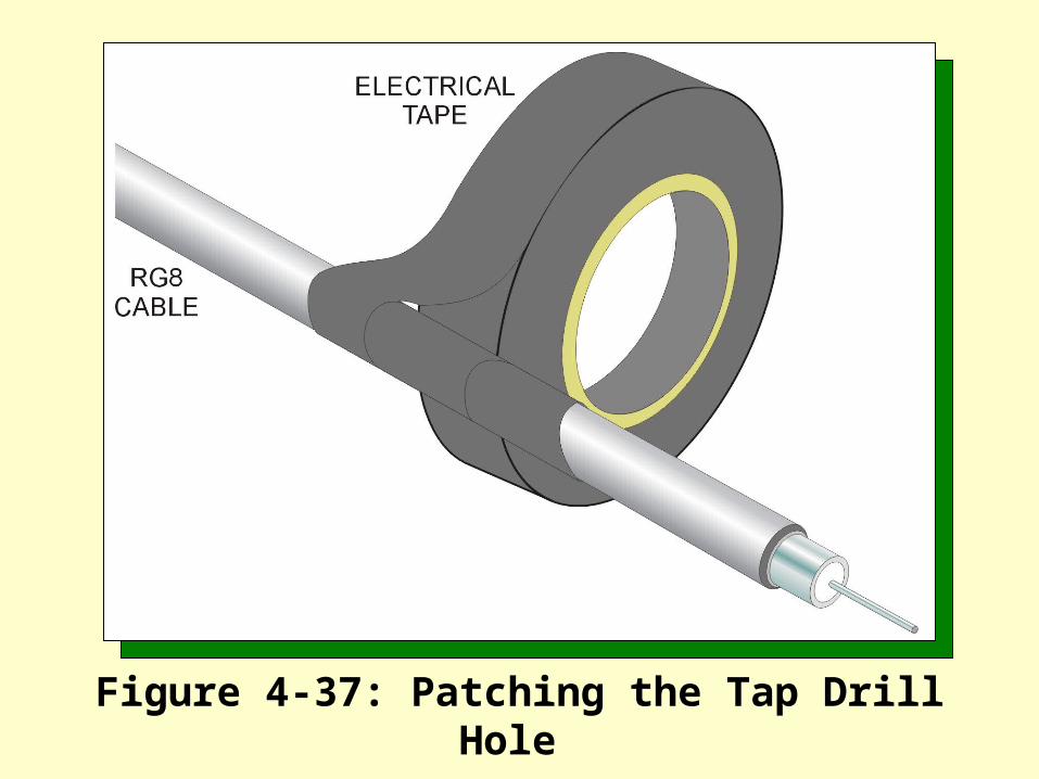
Figure 4-37: Patching the Tap Drill Hole

LAB 12 QUESTIONSLAB 12 QUESTIONS
Where should the Thicknet tap be physically located on a RG8 backbone cable?
11

LAB 12 QUESTIONSLAB 12 QUESTIONS
How many braid terminators are there in the tap body?
22

LAB 12 QUESTIONSLAB 12 QUESTIONS
Why must the drill hole be carefully inspected before threading the probe assembly into the tap body?
33

LAB 12 QUESTIONSLAB 12 QUESTIONS
How do you avoid drilling the hole too deeply when using the coring tool?
44

Figure 4-38: TP-PMD Wiring

REVIEW QUESTIONSREVIEW QUESTIONS
Which telco level rating applies to the standard telephone system?
11

REVIEW QUESTIONSREVIEW QUESTIONS
Which wiring category cleanly transmits 100 Mbps at 100 MHz?
22

REVIEW QUESTIONSREVIEW QUESTIONS
What is the maximum bandwidth of a Level 1 telecommunications system?
33

REVIEW QUESTIONSREVIEW QUESTIONS
What type of wire is typically used for Level 1 wiring?
44

REVIEW QUESTIONSREVIEW QUESTIONS
Where would Level 2-rated components be used?
55
REVIEW QUESTIONSREVIEW QUESTIONS
What type of termination method is typically used for Level 1 wiring?
66

REVIEW QUESTIONSREVIEW QUESTIONS
Are a 100 MHz line and a 100 Mbps transmission rate the same thing?
77

REVIEW QUESTIONSREVIEW QUESTIONS
What is attenuation, and what is its unit of measurement?
88

REVIEW QUESTIONSREVIEW QUESTIONS
What is ATM and where is it used?99

REVIEW QUESTIONSREVIEW QUESTIONS
What type of cable is specified for use in a 100baseT network?
1010