object placement as inverse motion plannninglis.csail.mit.edu/pubs/tlp/icra13_1509_fi.pdf ·...
TRANSCRIPT
Object Placement as Inverse Motion Planning
Anne Holladay1 Jennifer Barry1 Leslie Pack Kaelbling1 Tomas Lozano-Perez1
Abstract— We present an approach to robust placing thatuses movable surfaces in the environment to guide a poorlygrasped object into a goal pose. This problem is an instance ofthe inverse motion planning problem, in which we solve for aconfiguration of the environment that makes desired trajectorieslikely. To calculate the probability that an object will take aparticular trajectory, we model the physics of placing as amixture model of simple object motions. Our algorithm searchesover the possible configurations of the object and environmentand uses this model to choose the configuration most likely tolead to a successful place. We show that this algorithm allowsthe PR2 robot to execute placements that fail with traditionalplacing implementations.
I. INTRODUCTION
Robotic pick and place operations have been widelystudied, but much of the focus has been on the detailsof the pick operation, planning grasps for interestingly-shaped, deformable, or slippery objects. Classic pick andplace operations use rigid grasps so the place operation isusually straightforward. Given a goal pose for an object thatis rigidly attached to the robot, we calculate the pose of therobot’s end effector that will result in a correct placement ofthe object and then solve an inverse kinematics problem todetermine the robot’s configuration.
However, this approach to placing has limited applica-bility. Many robots have thick forearms so that, if theobject is originally grasped too close to its base, the robot’sforearm will collide with the table during placing. Similarly,a difference between the object’s relative orientation to therobot when it is picked and when it is placed can makethe place operation infeasible. Some objects are inherentlydifficult to place: wide, flat objects, such as plates or books,for example, are shaped such that there is only one way tograsp them, but this grasp leads to collisions during placing.Some of these failure modes can be seen in Figures 1 and 2.
Humans rarely place objects in such a completely con-strained manner. Instead, we tend to drop objects or balancethem against other surfaces. Robots, possessing much lessdexterous hands, should use these strategies, if anything,more often than humans. A robot with two arms should beable to use its other hand to increase the robustness of a
1MIT CSAIL {holladay, jbarry, lpk, tlp}@csail.mit.eduThis work was supported in part by the NSF under Grants No. 1117325
and No. 1122374. Any opinions, findings, and conclusions or recommen-dations expressed in this material are those of the author(s) and do notnecessarily reflect the views of the National Science Foundation. We alsogratefully acknowledge support from ONR MURI grant N00014-09-1-1051, from AFOSR grant FA2386-10-1-4135, from the Angle Research andInnovation Scholarship, and from the Singapore Ministry of Education undera grant to the Singapore-MIT International Design Center. We thank WillowGarage for the use of the PR2 robot as part of the PR2 Beta Program.
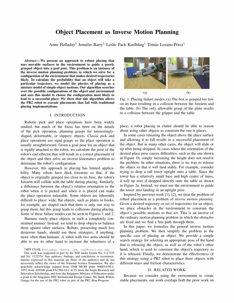
(a) (b)
Fig. 1: Placing failure modes. (a) The box is grasped too lowon its base resulting in a collision between the forearm andthe table. (b) The only allowable grasp of the plate resultsin a collision between the gripper and the table.
place; a robot placing in clutter should be able to reasonabout using other objects to constrain the one it places.
In some cases releasing the object above the place surfaceand allowing it to fall results in a successful placement ofthe object. But in many other cases, the object will slide ortip after being dropped. In cases where the orientation of thedesired place pose causes difficulties, such as the one shownin Figure 1b, simply increasing the height does not resolvethe problem. In other situations, there is no way to releasethe object so that it will land stably. For example, considertrying to drop a tall tower upright onto a table. Since thetower has a relatively small base and high center of mass,it will tip over if dropped directly onto the table as shownin Figure 2a. Instead, we must use the environment to guidethe tower into landing in an upright pose.
Inspired by previous work [1], [2], we treat the problem ofrobust placement as a problem of inverse motion planning.Given a desired trajectory or set of trajectories for an object,we place obstacles in the environment to constrain theobject’s possible motions to that set. This is an inverse ofthe ordinary motion planning problem in which the obstaclesare fixed and we find a free path through them.
In this paper, we formalize the general inverse motionplanning problem. We then simplify the problem in thespecific case of placing an object. We provide a simplesearch strategy for selecting an appropriate pose of the handthat is releasing the object, as well as of the robot’s otherhand, which is used to constrain the object’s trajectory asit is released. Finally, we demonstrate the effectiveness ofthis strategy using a PR2 robot to place three objects withdifferent mass and friction characteristics.
II. RELATED WORKBecause we consider using the environment to create
stable placements, our work overlaps both the prior work on

the pick and place task and also that of the inverse motionplanning problem. In this section, we discuss work from bothareas in more detail.
While there has been a significant amount of work in thearea of pick and place, most of the it has focused on choosinggrasps. Some approach the problem analytically [3], [4],while others [5], [6] learn grasps by example from humanoperators. However, these approaches do not consider con-straints from placing while choosing a grasp. Other work hasconsidered the problem of choosing a sequence of graspstaking into account the geometric constraints from a fixedenvironment placement [7], [8], but in all of this work, theenvironment has been treated as immutable. In this paper,we focus on the problem where the grasp is fixed, but wecan manipulate the environment as well as the object duringplacement.
Jiang et al. [9] address the problem of learning where inthe environment to place an object. Their algorithm learnsplacements for new objects in new environments based onsupport, stability and preferred configurations. In contrast,we focus on problems where the ending pose is specified,and try to rearrange the environment to result in that pose.
Paolini et al. [10] also approach the problem of placingusing machine learning. They gather statistics about thepossible ways to grasp an object and the subsequent proba-bility of placing success. Then given an object, a grasp, andpossible different placements for the object, they choose theplace location most likely to succeed. This is similar in spiritto our work, but we are given a grasp and a placement andwe reason about possible arrangements of the environment.
Our work explores partly “passive” approaches to place-ment, where we rely on the task dynamics as constraints onthe place operation. The idea of exploiting task dynamics toachieve precise placements has been explored by Erdmannand Mason [11], under the name “sensorless manipulation.”Erdmann and Mason address the problem of starting withobjects in an unknown orientation and finding a sequenceof motions that leave the object’s orientation completelydetermined. Although our work is not “sensorless”, the keyidea is also to exploit a (qualitative) characterization of thetask dynamics to choose actions to maximize the probabilityof successful placement.
In this work, we use the environment, including therobot’s other hand, to constrain the possible motions of anobject during placement. We view this as an instance ofthe inverse motion planning problem. The inverse motionplanning problem was originally proposed as an approach todesigning orienting devices for vibratory bowl feeders [1],[2], devices where shape interactions are exploited to filterout unwanted orientations of objects, preparatory to assemblyor machining operations [12].
III. PROBLEM DEFINITION
We begin by providing a general definition of the problemand then providing a specific example used throughout therest of the paper.
A. Inverse Motion Planning Problem
Let C be the joint configuration space of the robot and allmovable objects in the environment. Throughout this paper,we assume that there is a single object that moves throughthe environment. The problem is to arrange the environment,subject to a set of constraints, so that the object will followone of a set of pre-defined trajectories.
Formally, an inverse motion planning problem is charac-terized by a tuple 〈c0, o, OM , R,P,Γ〉 where: c0 ∈ C isthe initial configuration of the robot and objects, o is anobject, OM is a set of movable objects (possibly including arobot), R(c,OM ) ⊆ C is a reachability function that returnsthe set of configurations that can be reached from c bymoving the elements of OM , P is a set of desired trajectoriesfor o, and Γ(P | c) gives the probability that the objectfollows trajectory P assuming that the environment started inconfiguration c ∈ C. In this formulation, there is no choice ofaction that can affect the object’s path once the environmentis arranged so the initial configuration entirely determinesthe probability that the object will follow trajectory P .
The solution to an inverse motion planning problem is theconfiguration of the movable objects,
c∗ = arg maxc∈R(c0,OM )
∫P∈P
Γ(P | c) (1)
that has the highest probability of resulting in a goal trajec-tory. The configuration c∗ is some configuration the robotcan reach from its starting configuration c0, possibly byrearranging its environment.
We work with a subset of this problem where R, Γ, andP have a specific structure.
B. Placement Problem
The placement problem is a specific choice for the type ofgoal trajectories and the reachability function R in the defini-tion of the inverse motion planning problem. We assume thatone of the objects is being held by a robot or is otherwisepoised to be released and that it will fall ballistically throughthe environment. We have a specific pose or set of poses atwhich we wish it to land. Specifically, a placement problemis a tuple 〈c0, o, OM , OF , TL, G,Φ〉 where c0, o, and OMare as described for the inverse motion planning problem. Gis a set of “goal” poses for the object, and for configurationsc1, c2 ∈ C, Φ(c2 | c1) is the probability that the systemcomes to rest in c2 assuming that it started in configurationc1. G implicitly defines the set of goal trajectories as anytrajectories in which the object ends in a pose in G. Let P(c2)be the set of trajectories ending in c2. Then Φ is related toΓ of the definition of inverse motion planning by
Φ(c2 | c1) =
∫P∈P(c2)
Γ(P | c1) . (2)
We also use a specific reachability function. OF is a setof fixed obstacles in the environment that cannot be movedand TL is a rigid transformation from the pose of o to somelink L on the robot. R(c,OM ) is now defined implicitly asthe set of configurations c′ of that can be reached from c
subject to the constraints that o remains fixed to L and thatsome path from c′ to c is collision free.
By taking TL as input, we decouple the solution to theplace portion of the pick and place task from the solution tothe pick portion. Rather than tailor the grasp to the specificplace operation, we attempt to find a place operation thathas some probability of success with whatever grasp waschosen. Future work could explore choosing grasps whenwe can manipulate the environment.
We call placement problems in which the set OM containsonly the object and the kinematic chain from which theobject is being released passive placement problems. Passiveplacement problems are not trivial; the angle and height ofthe end effector can limit the object’s possible trajectoriesand should be chosen to ensure the best result.
We call problems that involve moving other objects orother parts of the robot robust placement problems.
C. Transition model
In this section, we present the transition model Φ, which isan approximation of the actual dynamics. A place operationconsists of two steps:
1) Releasing the held object o and2) Retracting the robot’s end effector away from o.
The outcome of a place operation is the pose of o after bothof these steps; it is successful if the resulting pose of o is ingoal set G. We assume that there is a single nominal desiredpose g∗ ∈ G and that the rest of the poses in g are clusteredaround g∗; furthermore, assume that when o is in pose g∗, itis resting on a surface, which we will call the place surface.
To model the transition dynamics, we could use a high-fidelity physics simulator. However, it is difficult and compu-tationally intensive to model contact forces, and physics sim-ulation requires determining coefficients of friction, elastic-ity, and other parameters that are hard to measure accuratelyand tend to change over time. Moreover, as we will show, wedo not require a high-fidelity physics simulator to robustlyplace an object. Instead, we simply need an estimate of theprobability of a successful place operation given a startingconfiguration and a characterization of the possible failuremodes. For example, a tall, thin object might tip onto itsside after being released. To prevent this, we need to knowto which side the object is most likely to tip, but not its exactconfiguration as it tips.
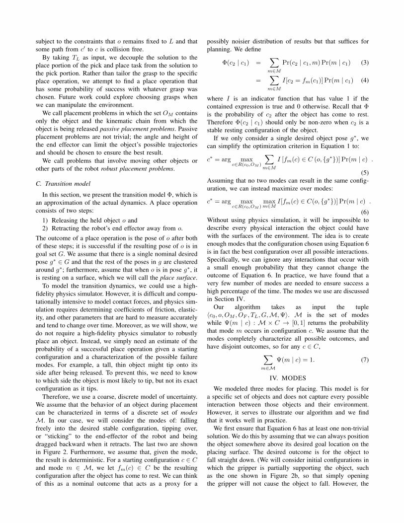
Therefore, we use a coarse, discrete model of uncertainty.We assume that the behavior of an object during placementcan be characterized in terms of a discrete set of modesM. In our case, we will consider the modes of: fallingfreely into the desired stable configuration, tipping over,or “sticking” to the end-effector of the robot and beingdragged backward when it retracts. The last two are shownin Figure 2. Furthermore, we assume that, given the mode,the result is deterministic. For a starting configuration c ∈ Cand mode m ∈ M, we let fm(c) ∈ C be the resultingconfiguration after the object has come to rest. We can thinkof this as a nominal outcome that acts as a proxy for a
possibly noisier distribution of results but that suffices forplanning. We define
Φ(c2 | c1) =∑m∈M
Pr(c2 | c1,m) Pr(m | c1) (3)
=∑m∈M
I[c2 = fm(c1)] Pr(m | c1) (4)
where I is an indicator function that has value 1 if thecontained expression is true and 0 otherwise. Recall that Φis the probability of c2 after the object has come to rest.Therefore Φ(c2 | c1) should only be non-zero when c2 is astable resting configuration of the object.
If we only consider a single desired object pose g∗, wecan simplify the optimization criterion in Equation 1 to:
c∗ = arg maxc∈R(c0,OM )
∑m∈M
I [fm(c) ∈ C (o, {g∗})] Pr(m | c) .
(5)Assuming that no two modes can result in the same config-uration, we can instead maximize over modes:
c∗ = arg maxc∈R(c0,OM )
maxm∈M
I[fm(c) ∈ C(o, {g∗})] Pr(m | c) .
(6)Without using physics simulation, it will be impossible todescribe every physical interaction the object could havewith the surfaces of the environment. The idea is to createenough modes that the configuration chosen using Equation 6is in fact the best configuration over all possible interactions.Specifically, we can ignore any interactions that occur witha small enough probability that they cannot change theoutcome of Equation 6. In practice, we have found that avery few number of modes are needed to ensure success ahigh percentage of the time. The modes we use are discussedin Section IV.
Our algorithm takes as input the tuple〈c0, o, OM , OF , TL, G,M,Ψ〉. M is the set of modeswhile Ψ(m | c) : M× C → [0, 1] returns the probabilitythat mode m occurs in configuration c. We assume that themodes completely characterize all possible outcomes, andhave disjoint outcomes, so for any c ∈ C,∑
m∈MΨ(m | c) = 1. (7)
IV. MODES
We modeled three modes for placing. This model is fora specific set of objects and does not capture every possibleinteraction between those objects and their environment.However, it serves to illustrate our algorithm and we findthat it works well in practice.
We first ensure that Equation 6 has at least one non-trivialsolution. We do this by assuming that we can always positionthe object somewhere above its desired goal location on theplacing surface. The desired outcome is for the object tofall straight down. (We will consider initial configurations inwhich the gripper is partially supporting the object, suchas the one shown in Figure 2b, so that simply openingthe gripper will not cause the object to fall. However, the
(a) (b) (c)
Fig. 2: Failure modes for the different objects. (a) The tower could tip over. (b)-(c) The plates got caught on the gripperand dragged during retreat.
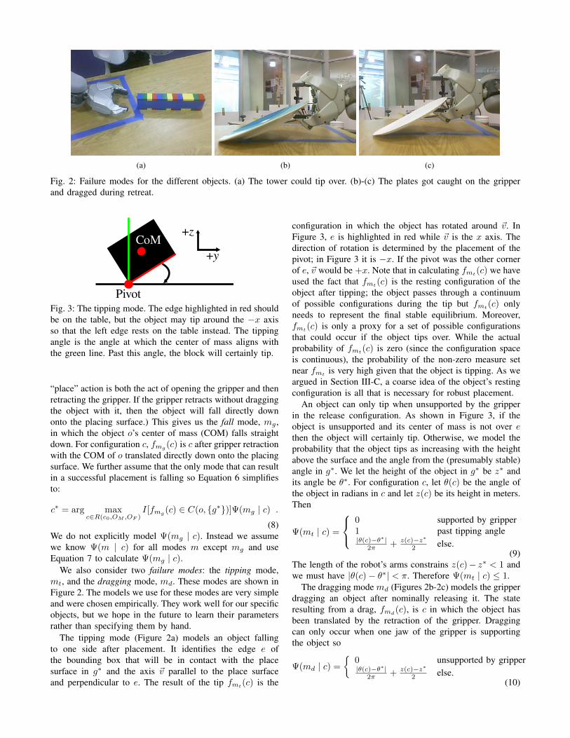
+y
+z
Pivot
CoM
Fig. 3: The tipping mode. The edge highlighted in red shouldbe on the table, but the object may tip around the −x axisso that the left edge rests on the table instead. The tippingangle is the angle at which the center of mass aligns withthe green line. Past this angle, the block will certainly tip.
“place” action is both the act of opening the gripper and thenretracting the gripper. If the gripper retracts without draggingthe object with it, then the object will fall directly downonto the placing surface.) This gives us the fall mode, mg ,in which the object o’s center of mass (COM) falls straightdown. For configuration c, fmg
(c) is c after gripper retractionwith the COM of o translated directly down onto the placingsurface. We further assume that the only mode that can resultin a successful placement is falling so Equation 6 simplifiesto:
c∗ = arg maxc∈R(c0,OM ,OF )
I[fmg (c) ∈ C(o, {g∗})]Ψ(mg | c) .
(8)We do not explicitly model Ψ(mg | c). Instead we assumewe know Ψ(m | c) for all modes m except mg and useEquation 7 to calculate Ψ(mg | c).
We also consider two failure modes: the tipping mode,mt, and the dragging mode, md. These modes are shown inFigure 2. The models we use for these modes are very simpleand were chosen empirically. They work well for our specificobjects, but we hope in the future to learn their parametersrather than specifying them by hand.
The tipping mode (Figure 2a) models an object fallingto one side after placement. It identifies the edge e ofthe bounding box that will be in contact with the placesurface in g∗ and the axis ~v parallel to the place surfaceand perpendicular to e. The result of the tip fmt(c) is the
configuration in which the object has rotated around ~v. InFigure 3, e is highlighted in red while ~v is the x axis. Thedirection of rotation is determined by the placement of thepivot; in Figure 3 it is −x. If the pivot was the other cornerof e, ~v would be +x. Note that in calculating fmt
(c) we haveused the fact that fmt
(c) is the resting configuration of theobject after tipping; the object passes through a continuumof possible configurations during the tip but fmt(c) onlyneeds to represent the final stable equilibrium. Moreover,fmt
(c) is only a proxy for a set of possible configurationsthat could occur if the object tips over. While the actualprobability of fmt(c) is zero (since the configuration spaceis continuous), the probability of the non-zero measure setnear fmt
is very high given that the object is tipping. As weargued in Section III-C, a coarse idea of the object’s restingconfiguration is all that is necessary for robust placement.
An object can only tip when unsupported by the gripperin the release configuration. As shown in Figure 3, if theobject is unsupported and its center of mass is not over ethen the object will certainly tip. Otherwise, we model theprobability that the object tips as increasing with the heightabove the surface and the angle from the (presumably stable)angle in g∗. We let the height of the object in g∗ be z∗ andits angle be θ∗. For configuration c, let θ(c) be the angle ofthe object in radians in c and let z(c) be its height in meters.Then
Ψ(mt | c) =
0 supported by gripper1 past tipping angle|θ(c)−θ∗|
2π + z(c)−z∗2 else.
(9)The length of the robot’s arms constrains z(c)− z∗ < 1 andwe must have |θ(c)− θ∗| < π. Therefore Ψ(mt | c) ≤ 1.
The dragging mode md (Figures 2b-2c) models the gripperdragging an object after nominally releasing it. The stateresulting from a drag, fmd
(c), is c in which the object hasbeen translated by the retraction of the gripper. Draggingcan only occur when one jaw of the gripper is supportingthe object so
Ψ(md | c) =
{0 unsupported by gripper|θ(c)−θ∗|
2π + z(c)−z∗2 else.
(10)

Note that the probability of dragging is only non-zero if theprobability of tipping is zero and vice-versa.
The last parts of Equations 9 and 10 are the same, whichmay seem counter-intuitive as it seems a lower angle shouldresult in less dragging. However, we found that with thegrippers of the robot and the objects that we used, a highangle resulted in the object getting stuck on a gripper padand dragged more often.
V. ALGORITHM
Our algorithm for robust placing, illustrated in Figure 4,takes as input the tuple 〈c0, o, OM , OF , TL, G,M,Ψ〉 andoutputs an approximation to the configuration that maximizesEquation 8.
Searching over all the configurations c ∈ R(c0, OM )for one that maximizes Equation 8 is, for high-dimensionalconfiguration spaces, a computationally intractable approach.Therefore, we split the search into two parts. In practice, wefound that the pose of the end effector when releasing theobject had the largest effect on the success of the place.Thus, we first choose a release configuration assuming therest of the environment stays constant. Specifically, we searchfor the release configuration r for which r ∈ R(c0, OM ),no elements of OM differ from their configuration in c0except o and its attached kinematic chain, fmg (r) ∈ G, andEquation 8 is maximized. Let CR be the set of all configura-tions for which no elements of OM except the object and itsattached chain have moved from their configurations in c0and for all r ∈ CR, fmg
(r) ∈ G. All configurations in CRhave the object positioned at or above its goal pose. We wantto choose the configuration r ∈ CR ∩R(c0, OM ) for whichΨ(mg | r) is maximized. We do this by discretizing CRinto a finite set of configurations {r1, ..., rn}, ordering it bydecreasing Ψ(mg | ri), and choosing the first configurationr for which there is a collision free trajectory for the robotand object to move to r. This is shown in Figure 4a.
Given the release configuration r, the algorithm finds theconfiguration of the elements in OM other than the objectand its attached kinematic chain in which the place has thegreatest probability of success. We first evaluate fm(r) foreach mode m besides the fall mode mg and order theseby decreasing probability (Figure 4b). We then place themovable objects in the environment to prevent the most likelyfailure modes. Currently, we calculate the locations for theseobjects analytically. For our failure modes m, fm(c) is eithera pure rotation (tipping) or a pure translation (dragging) offmg
(c). We identify this axis of rotation or translation andplace objects accordingly. For example, if the object is mostlikely to tip around the −x axis, we place a block next tothe object along the +y axis as shown in Figure 4c. If theobject is likely to drag along the −y axis, we place a blocknext to the object along the −y axis.
VI. RESULTS
We implemented the algorithm described in Section V onthe Willow Garage PR2 robot. The PR2 has two arms, eachwith seven degrees of freedom, and parallel jaw grippers at
Object Dropping Passive Placing Robust PlacingTower 1/10 0/10 10/10
Plastic Plate 0/10 10/10 10/10Paper Plate 0/10 2/10 10/10
TABLE I: Success ratios for dropping (benchmark), passive,and robust placing algorithms. A trial was considered asuccess if the object came to rest at or near its goal pose.Failures occurred when the tower tipped over or the plateswere dragged.
the end of each arm. We modeled the PR2’s empty gripperas a movable block.
We tested the algorithm using three different objects andthree different placing schemes. The objects used were atower of legos, a plastic plate, and a paper plate all shownin Figure 5. The three placing algorithms we tested were:• Dropping (Benchmark Algorithm): With the grasps
used, classic placing is unable to find a solution becausethe gripper collides with the table as shown in Figure 7.The classic fix for this problem is to simply raise thegripper until it is no longer in contact with the table.Therefore, our benchmark algorithm was simply to dropthe object from 5cm above its goal pose.
• Passive Placing: We planned for a placement using thealgorithm from Section V considering only the objectand the arm holding the object as movable objects inthe environment.
• Robust Placing: We planned for a placement using thealgorithm from Section V considering the object, thearm holding the object and the robot’s empty gripper asmovable objects in the environment.
The three objects with which we experimented are difficultto place. The tower tends to tip over if not placed carefullywhile the plates get caught on the gripper and dragged duringthe retraction. These failure modes are shown in Figure 2. Weran 10 trials of each placing algorithm for each object andrecorded the number of times the object came to rest at ornear its goal pose. The results are shown in Table I. Examplerelease configurations for robust and passive placing aregiven in Figure 5. Example trajectories are shown on ourwebsite2 and in the accompanying video.
To show that the robust placing does not introduce toomuch variance in the final pose, we also show the final poseafter each successful robust place overlaid in Figure 6. Thegoal pose was the same each time.
VII. DISCUSSION
The tower and the plate induce two fundamentally dif-ferent types of failure of classic placing. The tower can besuccessfully placed using classic placing when it is graspednear its middle or top, but not when grasped near its base.On the other hand, the plate can only fit into the gripperusing the grasp shown in Figure 5. The plate can never besuccessfully placed using the classic approach to placing.
2http://people.csail.mit.edu/holladay/placing.html

(a) (b) (c)
Fig. 4: A simple algorithm for robust placing. (a) We first search over release configurations for the configuration with thehighest probability of success. (b) Given the release configuration, we evaluate the outcomes of the failure modes. Tippingcauses a rotation around the −x axis while dragging causes a translation along the −y axis as shown by the red arrows.We order these by decreasing probability. (c) Given the release configuration r found in step (a) and the order of the failuremode outcomes found in step (b), we use the movable objects - in this case, the robot’s empty gripper - to block the mostlikely failure modes.
(a)
(b)
Fig. 5: Example release configurations. (a) Passive placing results. (b) Robust placing results. Example trajectories are shownon our website2.
For both the tower and the plates, just dropping them doesnot work. In the case of the tower this is because it is unstableenough that allowing it to fall almost any distance results init tipping over. Thus for the tower, both dropping and passiveplacing give very poor results. With robust placing, however,the tip mode allows us to reason about the possibility of theobject falling over. Tip predicts that the tower will rotatearound the edge that would contact the surface so in thiscase it predicts a rotation out of the open gripper. Figure 5shows the tower tipped in this direction. When analyzingthe possible failure modes, we note this non-zero transitionprobability and bring the robot’s other hand to constrain it
(the tower is kept from tipping by the robot’s wrist). Bymanipulating the environment, we were able to successfullyplace the tower. Note that in our implementation we usedthe other hand to constrain the placement, but in theory wecould also use additional objects in the environment.
Both plates are supported by the gripper during placementand therefore cannot tip. However, this also means that whenthe gripper releases the plate, part of the plate is alreadyresting on the table so that gravity does not cause it to falldirectly out of the gripper. In the case of dropping, thisresulted in the plate being dragged back with the gripperevery time. If the plate was not removed manually from the
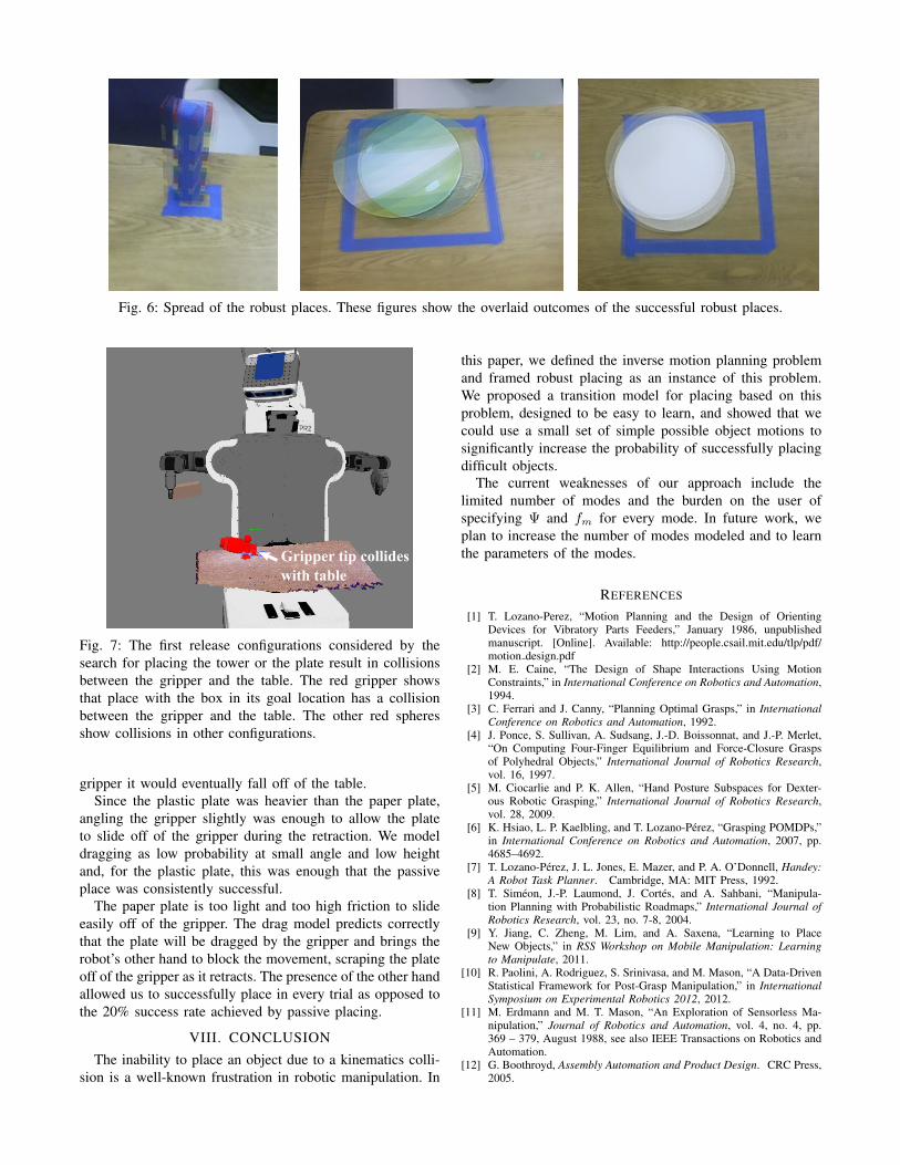
Fig. 6: Spread of the robust places. These figures show the overlaid outcomes of the successful robust places.
Gripper tip collides with table
Fig. 7: The first release configurations considered by thesearch for placing the tower or the plate result in collisionsbetween the gripper and the table. The red gripper showsthat place with the box in its goal location has a collisionbetween the gripper and the table. The other red spheresshow collisions in other configurations.
gripper it would eventually fall off of the table.Since the plastic plate was heavier than the paper plate,
angling the gripper slightly was enough to allow the plateto slide off of the gripper during the retraction. We modeldragging as low probability at small angle and low heightand, for the plastic plate, this was enough that the passiveplace was consistently successful.
The paper plate is too light and too high friction to slideeasily off of the gripper. The drag model predicts correctlythat the plate will be dragged by the gripper and brings therobot’s other hand to block the movement, scraping the plateoff of the gripper as it retracts. The presence of the other handallowed us to successfully place in every trial as opposed tothe 20% success rate achieved by passive placing.
VIII. CONCLUSIONThe inability to place an object due to a kinematics colli-
sion is a well-known frustration in robotic manipulation. In
this paper, we defined the inverse motion planning problemand framed robust placing as an instance of this problem.We proposed a transition model for placing based on thisproblem, designed to be easy to learn, and showed that wecould use a small set of simple possible object motions tosignificantly increase the probability of successfully placingdifficult objects.
The current weaknesses of our approach include thelimited number of modes and the burden on the user ofspecifying Ψ and fm for every mode. In future work, weplan to increase the number of modes modeled and to learnthe parameters of the modes.
REFERENCES
[1] T. Lozano-Perez, “Motion Planning and the Design of OrientingDevices for Vibratory Parts Feeders,” January 1986, unpublishedmanuscript. [Online]. Available: http://people.csail.mit.edu/tlp/pdf/motion design.pdf
[2] M. E. Caine, “The Design of Shape Interactions Using MotionConstraints,” in International Conference on Robotics and Automation,1994.
[3] C. Ferrari and J. Canny, “Planning Optimal Grasps,” in InternationalConference on Robotics and Automation, 1992.
[4] J. Ponce, S. Sullivan, A. Sudsang, J.-D. Boissonnat, and J.-P. Merlet,“On Computing Four-Finger Equilibrium and Force-Closure Graspsof Polyhedral Objects,” International Journal of Robotics Research,vol. 16, 1997.
[5] M. Ciocarlie and P. K. Allen, “Hand Posture Subspaces for Dexter-ous Robotic Grasping,” International Journal of Robotics Research,vol. 28, 2009.
[6] K. Hsiao, L. P. Kaelbling, and T. Lozano-Perez, “Grasping POMDPs,”in International Conference on Robotics and Automation, 2007, pp.4685–4692.
[7] T. Lozano-Perez, J. L. Jones, E. Mazer, and P. A. O’Donnell, Handey:A Robot Task Planner. Cambridge, MA: MIT Press, 1992.
[8] T. Simeon, J.-P. Laumond, J. Cortes, and A. Sahbani, “Manipula-tion Planning with Probabilistic Roadmaps,” International Journal ofRobotics Research, vol. 23, no. 7-8, 2004.
[9] Y. Jiang, C. Zheng, M. Lim, and A. Saxena, “Learning to PlaceNew Objects,” in RSS Workshop on Mobile Manipulation: Learningto Manipulate, 2011.
[10] R. Paolini, A. Rodriguez, S. Srinivasa, and M. Mason, “A Data-DrivenStatistical Framework for Post-Grasp Manipulation,” in InternationalSymposium on Experimental Robotics 2012, 2012.
[11] M. Erdmann and M. T. Mason, “An Exploration of Sensorless Ma-nipulation,” Journal of Robotics and Automation, vol. 4, no. 4, pp.369 – 379, August 1988, see also IEEE Transactions on Robotics andAutomation.
[12] G. Boothroyd, Assembly Automation and Product Design. CRC Press,2005.