object oriented software development and uml
DESCRIPTION
Object Oriented Software Development and UML. Why OO?. Benefits of object-oriented programming Symptoms of software development problems Root causes of project failure Software development best practices. Benefits of OO programming. OOA/OOD/OOP is good for: Analyzing user requirements - PowerPoint PPT PresentationTRANSCRIPT

Object Oriented Software Development and UML
Why OO?
• Benefits of object-oriented programming
• Symptoms of software development problems
• Root causes of project failure
• Software development best practices
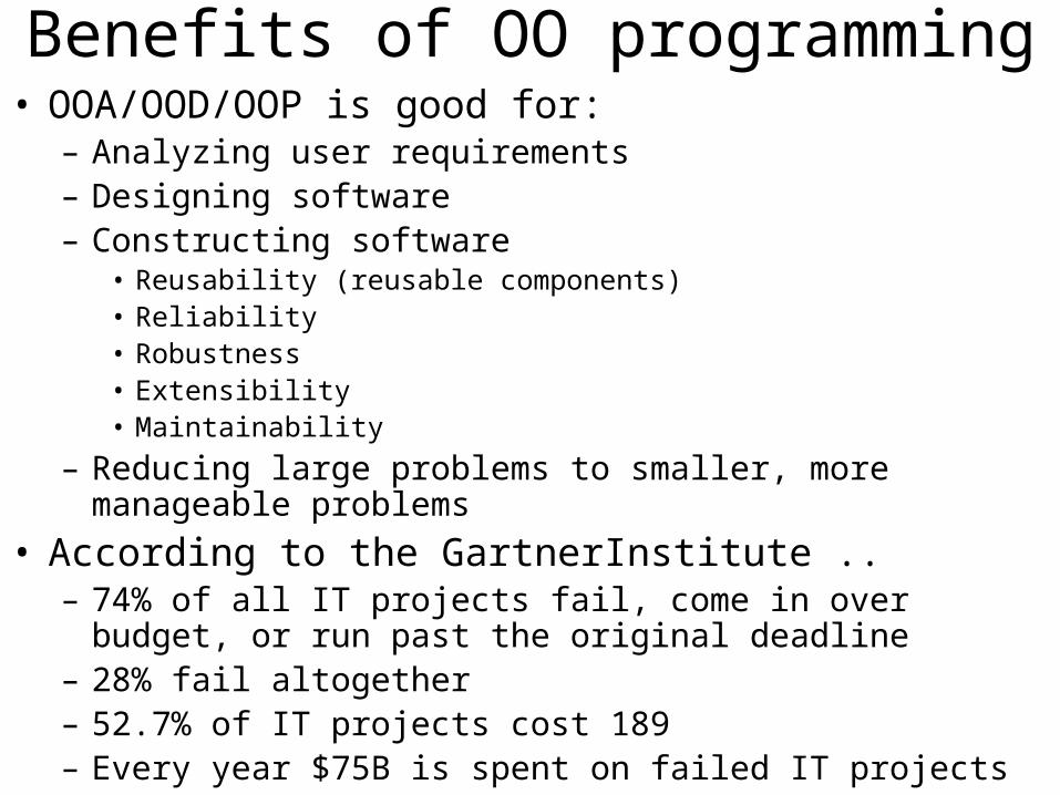
Benefits of OO programming• OOA/OOD/OOP is good for:
– Analyzing user requirements– Designing software– Constructing software
• Reusability (reusable components)• Reliability• Robustness• Extensibility• Maintainability
– Reducing large problems to smaller, more manageable problems
• According to the GartnerInstitute ..– 74% of all IT projects fail, come in over budget, or run past the
original deadline– 28% fail altogether– 52.7% of IT projects cost 189– Every year $75B is spent on failed IT projects
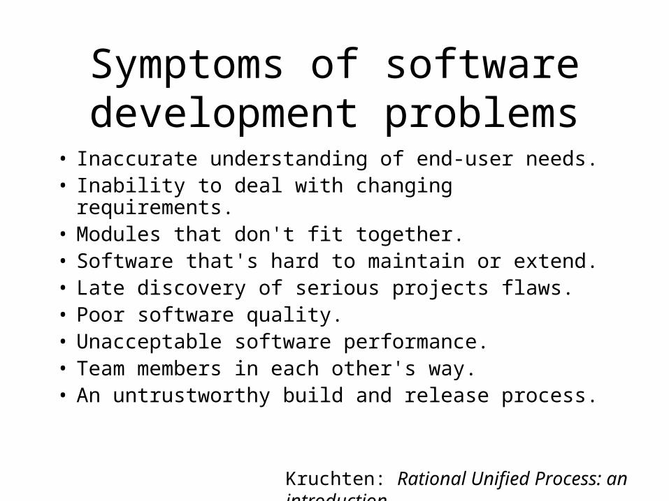
Symptoms of software development problems
• Inaccurate understanding of end-user needs. • Inability to deal with changing requirements. • Modules that don't fit together. • Software that's hard to maintain or extend. • Late discovery of serious projects flaws. • Poor software quality. • Unacceptable software performance. • Team members in each other's way. • An untrustworthy build and release process.
Kruchten: Rational Unified Process: an introduction
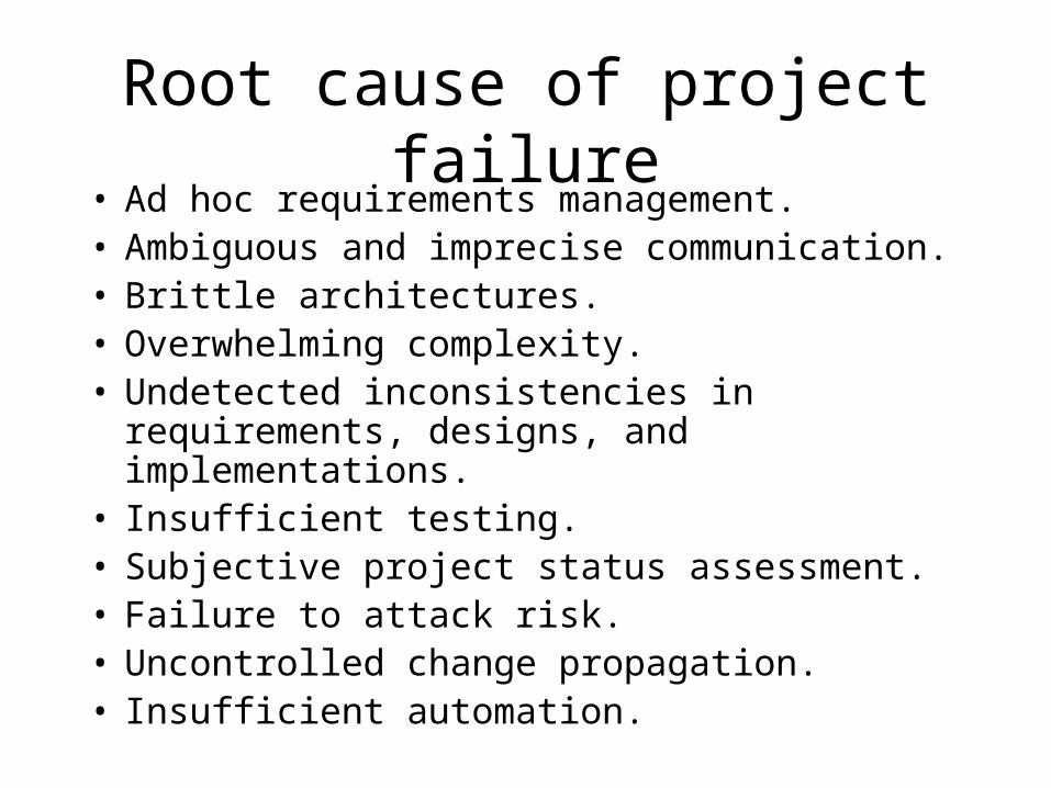
Root cause of project failure• Ad hoc requirements management. • Ambiguous and imprecise communication. • Brittle architectures. • Overwhelming complexity. • Undetected inconsistencies in requirements,
designs, and implementations. • Insufficient testing. • Subjective project status assessment. • Failure to attack risk. • Uncontrolled change propagation. • Insufficient automation.
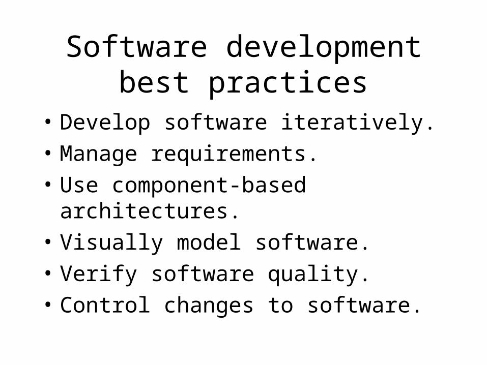
Software development best practices
• Develop software iteratively.
• Manage requirements.
• Use component-based architectures.
• Visually model software.
• Verify software quality.
• Control changes to software.
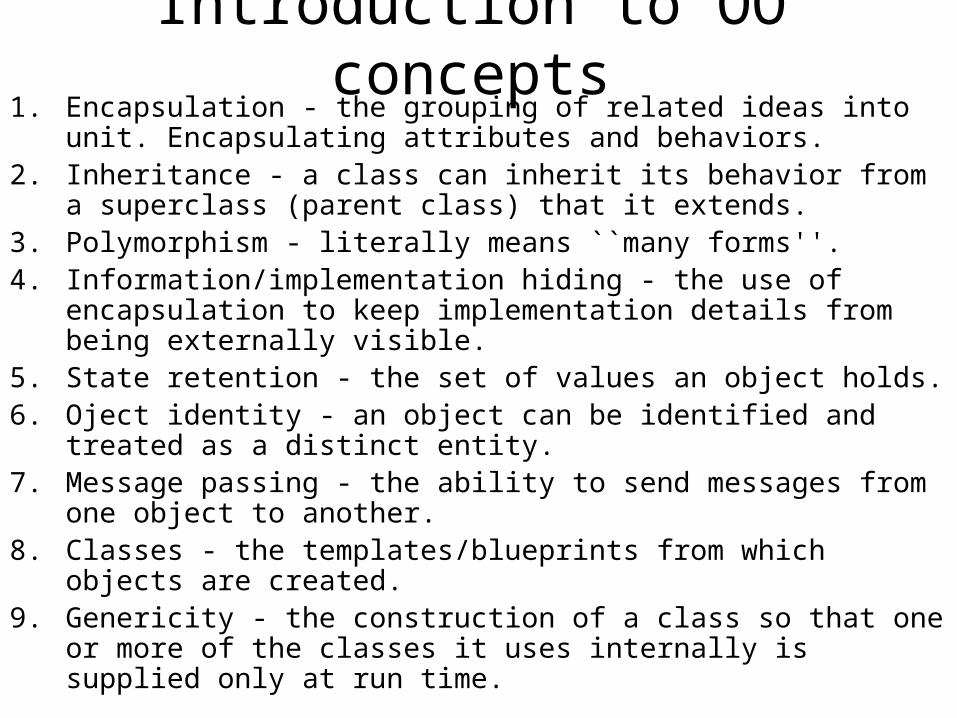
Introduction to OO concepts1. Encapsulation - the grouping of related ideas into unit.
Encapsulating attributes and behaviors. 2. Inheritance - a class can inherit its behavior from a superclass
(parent class) that it extends. 3. Polymorphism - literally means ``many forms''. 4. Information/implementation hiding - the use of encapsulation to
keep implementation details from being externally visible. 5. State retention - the set of values an object holds. 6. Oject identity - an object can be identified and treated as a distinct
entity. 7. Message passing - the ability to send messages from one object to
another. 8. Classes - the templates/blueprints from which objects are created. 9. Genericity - the construction of a class so that one or more of the
classes it uses internally is supplied only at run time.
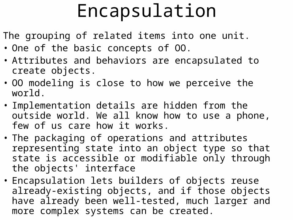
EncapsulationThe grouping of related items into one unit. • One of the basic concepts of OO. • Attributes and behaviors are encapsulated to create objects. • OO modeling is close to how we perceive the world. • Implementation details are hidden from the outside world.
We all know how to use a phone, few of us care how it works.
• The packaging of operations and attributes representing state into an object type so that state is accessible or modifiable only through the objects' interface
• Encapsulation lets builders of objects reuse already-existing objects, and if those objects have already been well-tested, much larger and more complex systems can be created.
Inheritance
• A subclass is derived from a superclass. An Employee is a Person.
• The subclass inherits the attributes and behavior of the superclass.
• The subclass can override the behavior of the superclass.
• Notice the use of the ``Is-A'' phrase to describe inheritance.
• Inheritance promotes re-use.
Polymorphism
• Literally means ``many forms''. • A method can have many different forms of behavior. • Commonly used between a set of classes that have a
common superclass. • The sender of a message does not have to know the
type/class of the receiver. • A single operation or attribute may be defined upon more
than one class and may take on different implementations in each of those classes.
• An attribute may point to different objects at different times

Abstraction with objects
• Abstraction: the act of identifying software artifacts to model the problem domain.
• Classes are abstracted from concepts. • This is the first step in identifying the classes that
will be used in your applications. • Better to have too many classes than too few. • When in doubt, make it a class.
Message passing• Objects communicate by sending messages. • Messages convey some form of information. • An object requests another object to carry out an activity by sending it
a message. • Most messages pass arguments back and forth. • Meilir Page-Jones defines three types of messages:
1. Informative - send information for the object to update itself. 2. Interrogative - ask an object to reveal some information about itself 3. Imperative - take some action on itself, or another object
• Grady Booch defines four types of messages: 1. Synchronous - receiving object starts only when it receives a message from a
sender, and it is ready. 2. Balking - sending object gives up on the message if the receiving object is not
ready to accept it. 3. Timeout - sending object waits only for a certain time period for the receiving
object to be ready to accept the message. 4. Asynchronous - sender can send a message to a receiver regardless of whether
the receiver is ready to receive it.
UML summary
• Unified Modeling Language - UML. • A modeling language, not a method. • Provides a graphical representation that allows
developers and architects to model a software system before the system is ever built.
• Analogy - an architect creating a blueprint before a house or office building is ever built.
• The UML does not specify a methodology or process. Therefore, saying ``We use the UML methodology is incorrect.''
Typical UML diagrams• Each UML diagram is designed to let developers and
customers view a software system from a different perspective and in varying degrees of abstraction. UML diagrams commonly created in visual modeling tools include
• Use case diagram
• Class diagram
• Interaction diagrams– Sequence diagram
– Collaboration diagram
• State diagram
• Activity diagram
• Physical diagrams– Component diagram
– Deployment diagram
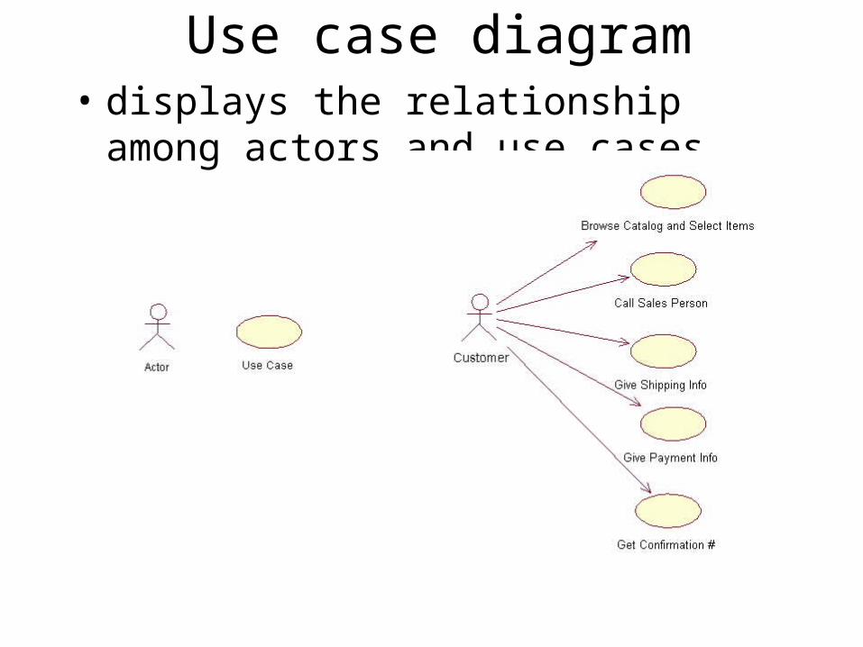
Use case diagram• displays the relationship among actors
and use cases
Class diagram• Models class structure and contents using design
elements such as classes, packages and objects. It also displays relationships such as containment, inheritance, associations and others
• Widely used to describe the types of objects in a system and their relationships.
• Model class structure and contents using design elements such as classes, packages and objects.2
• Describe three different perspectives when designing a system: conceptual, specification, implementation.
• These perspectives become evident as the diagram is created and help solidify the design.
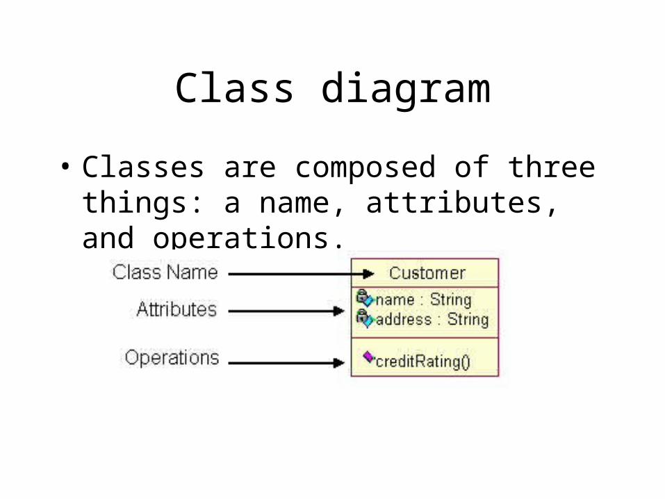
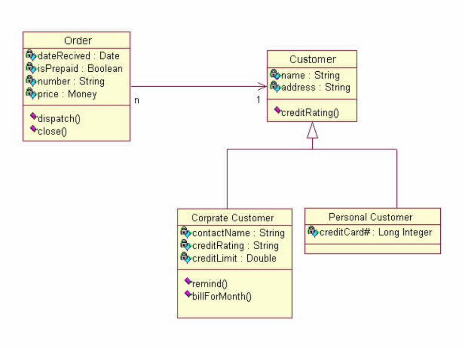
Class diagram
• Classes are composed of three things: a name, attributes, and operations.
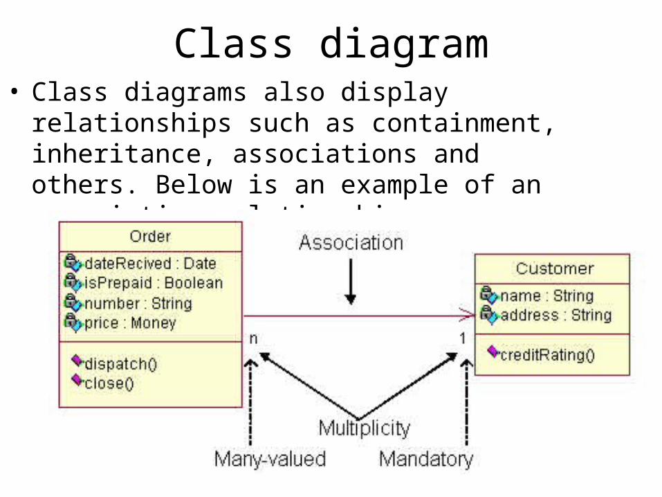
Class diagram• Class diagrams also display relationships such as
containment, inheritance, associations and others. Below is an example of an associative relationship
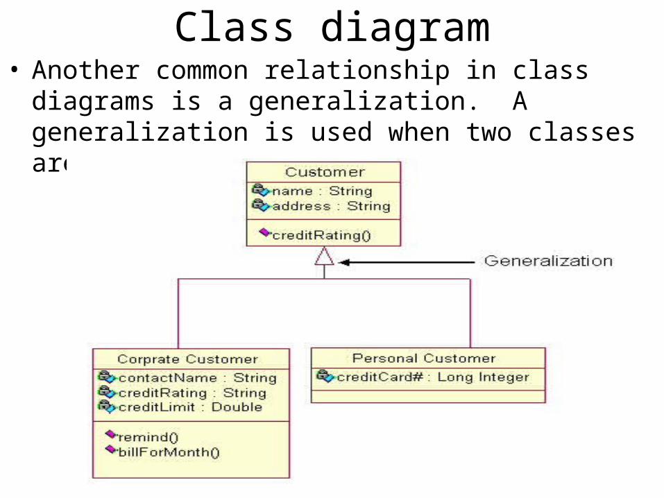
Class diagram• Another common relationship in class diagrams is a
generalization. A generalization is used when two classes are similar, but have some differences.
Class diagram
• When to Use: Class Diagrams– Class diagrams are used in nearly all Object
Oriented software designs. Use them to describe the Classes of the system and their relationships to each other
• How to Draw: Class Diagrams– Class diagrams are some of the most difficult UML
diagrams to draw. To draw detailed and useful diagrams a person would have to study UML and Object Oriented principles for a long time.
Class diagram
• Before drawing a class diagram consider the three different perspectives of the system the diagram will present; conceptual, specification, and implementation. Try not to focus on one perspective and try see how they all work together.
• When designing classes consider what attributes and operations it will have. Then try to determine how instances of the classes will interact with each other. These are the very first steps of many in developing a class diagram. However, using just these basic techniques one can develop a complete view of the software system.
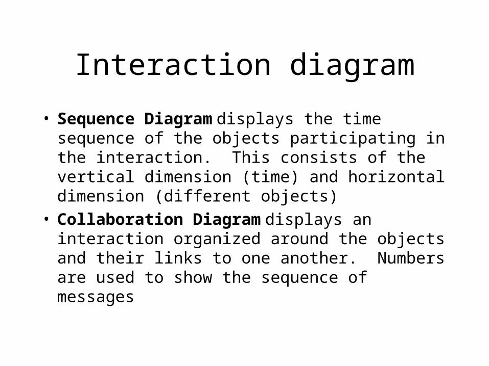
Interaction diagram
• Sequence Diagram displays the time sequence of the objects participating in the interaction. This consists of the vertical dimension (time) and horizontal dimension (different objects)
• Collaboration Diagram displays an interaction organized around the objects and their links to one another. Numbers are used to show the sequence of messages
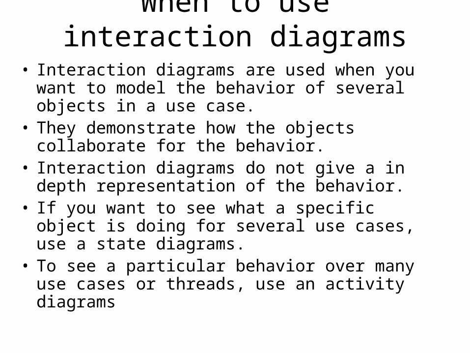
When to use interaction diagrams
• Interaction diagrams are used when you want to model the behavior of several objects in a use case.
• They demonstrate how the objects collaborate for the behavior.
• Interaction diagrams do not give a in depth representation of the behavior.
• If you want to see what a specific object is doing for several use cases, use a state diagrams.
• To see a particular behavior over many use cases or threads, use an activity diagrams
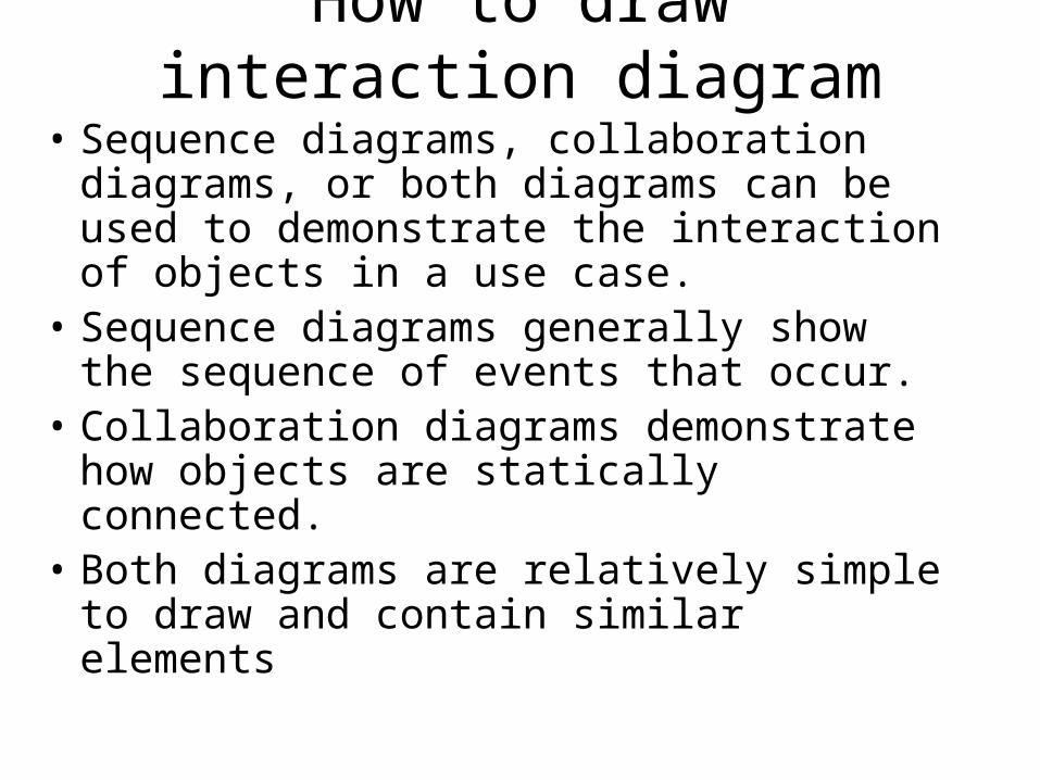
How to draw interaction diagram
• Sequence diagrams, collaboration diagrams, or both diagrams can be used to demonstrate the interaction of objects in a use case.
• Sequence diagrams generally show the sequence of events that occur.
• Collaboration diagrams demonstrate how objects are statically connected.
• Both diagrams are relatively simple to draw and contain similar elements
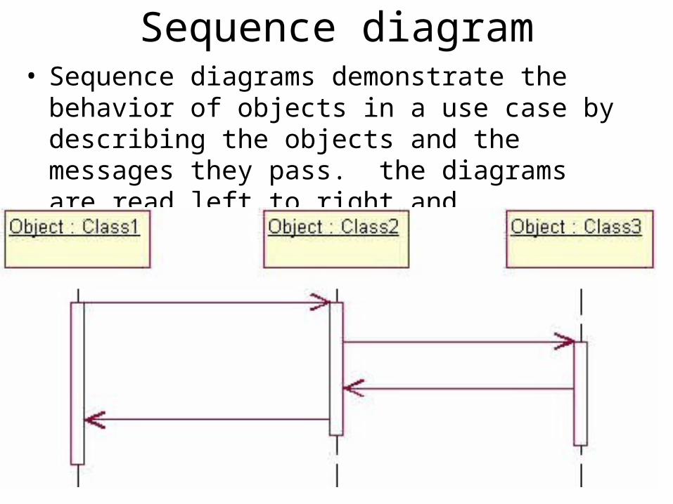
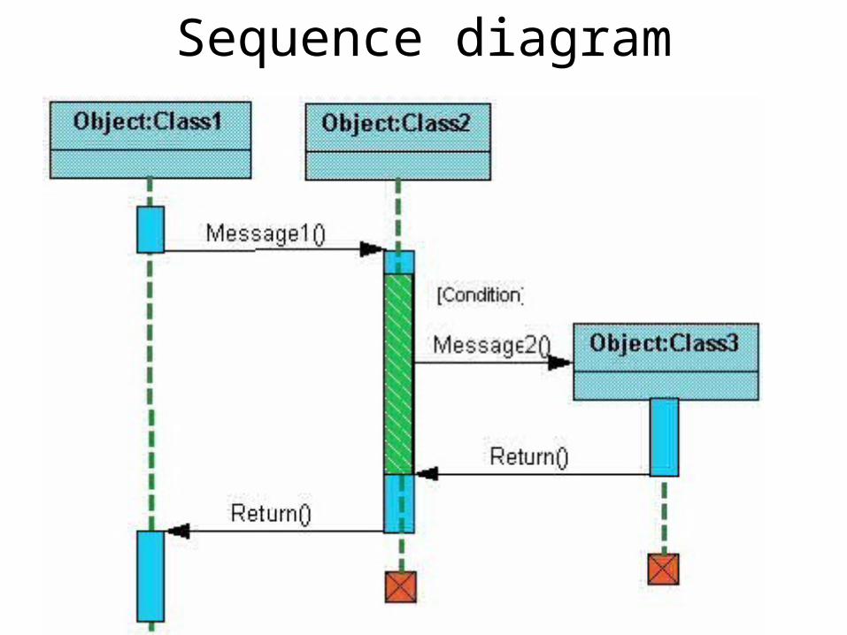
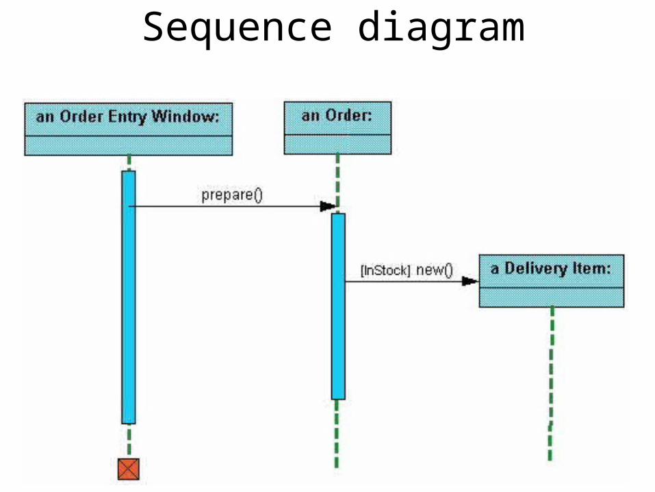
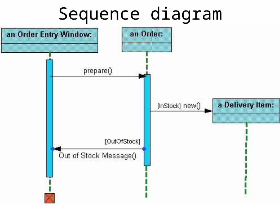
Sequence diagram• Sequence diagrams demonstrate the behavior of
objects in a use case by describing the objects and the messages they pass. the diagrams are read left to right and descending.
Sequence diagram
Sequence diagram
Sequence diagram
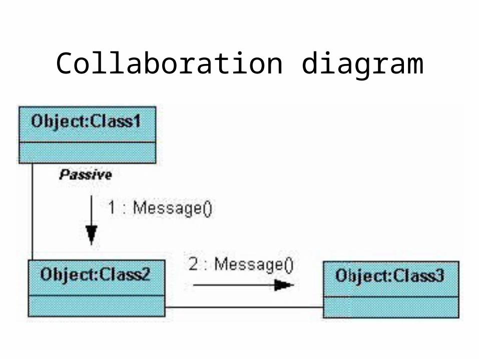
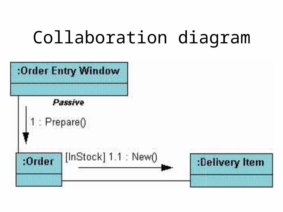
Collaboration diagram
• They show the relationship between objects and the order of messages passed between them
• The objects are listed as icons and arrows indicate the messages being passed between them.
• The numbers next to the messages are called sequence numbers. As the name suggests, they show the sequence of the messages as they are passed between the objects.
Collaboration diagram
Collaboration diagram
State diagram
• displays the sequences of states that an object of an interaction goes through during its life in response to received stimuli, together with its responses and actions
State diagram
• State diagrams are used to describe the behavior of a system.
• State diagrams describe all of the possible states of an object as events occur.
• Each diagram usually represents objects of a single class and track the different states of its objects through the system
When to use state diagram
• Use state diagrams to demonstrate the behavior of an object through many use cases of the system.
• Only use state diagrams for classes where it is necessary to understand the behavior of the object through the entire system.
• Not all classes will require a state diagram and state diagrams are not useful for describing the collaboration of all objects in a use case.
• State diagrams are often combined with other diagrams such as interaction diagrams and activity diagrams
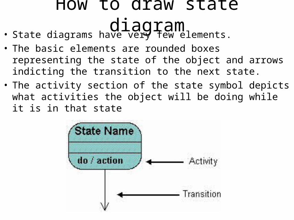
How to draw state diagram• State diagrams have very few elements. • The basic elements are rounded boxes representing
the state of the object and arrows indicting the transition to the next state.
• The activity section of the state symbol depicts what activities the object will be doing while it is in that state
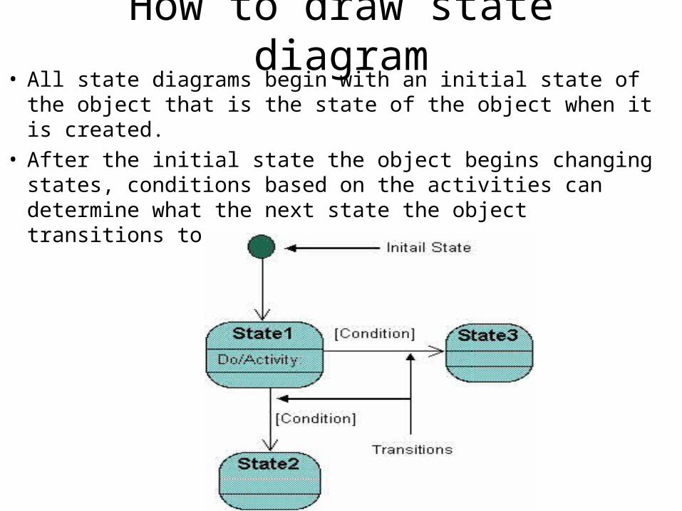
How to draw state diagram• All state diagrams begin with an initial state of the
object that is the state of the object when it is created. • After the initial state the object begins changing states,
conditions based on the activities can determine what the next state the object transitions to
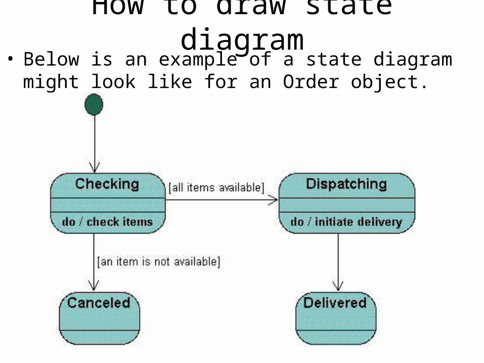
How to draw state diagram• Below is an example of a state diagram might look like
for an Order object.
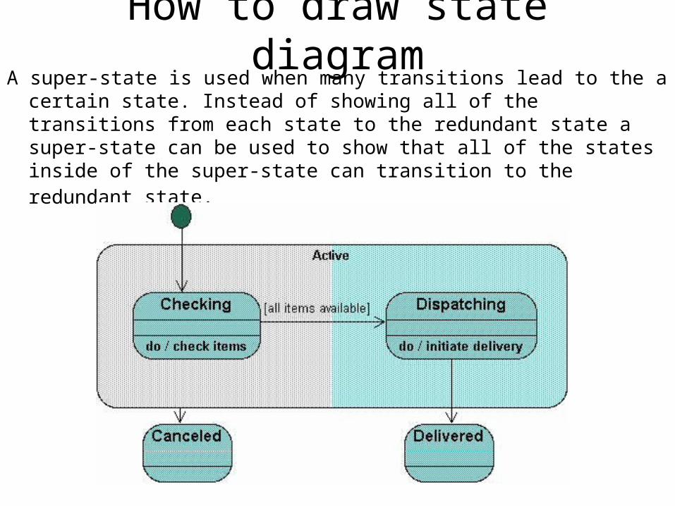
How to draw state diagramA super-state is used when many transitions lead to the a certain
state. Instead of showing all of the transitions from each state to the redundant state a super-state can be used to show that all of the states inside of the super-state can transition to the redundant state.
Activity diagram
• Displays a special state diagram where most of the states are action states and most of the transitions are triggered by completion of the actions in the source states.
• This diagram focuses on flows driven by internal processing
Activity diagram
• Activity diagrams describe the workflow behavior of a system.
• Activity diagrams are similar to state diagrams because activities are the state of doing something.
• The diagrams describe the state of activities by showing the sequence of activities performed.
• Activity diagrams can show activities that are conditional or parallel.
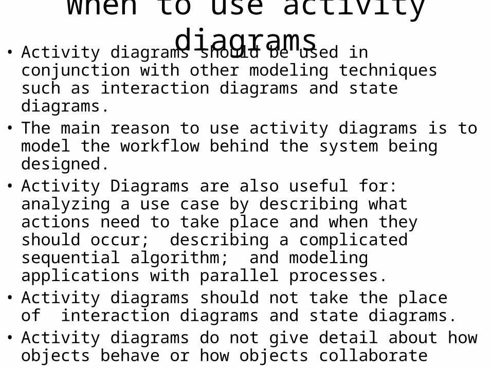
When to use activity diagrams• Activity diagrams should be used in conjunction with
other modeling techniques such as interaction diagrams and state diagrams.
• The main reason to use activity diagrams is to model the workflow behind the system being designed.
• Activity Diagrams are also useful for: analyzing a use case by describing what actions need to take place and when they should occur; describing a complicated sequential algorithm; and modeling applications with parallel processes.
• Activity diagrams should not take the place of interaction diagrams and state diagrams.
• Activity diagrams do not give detail about how objects behave or how objects collaborate
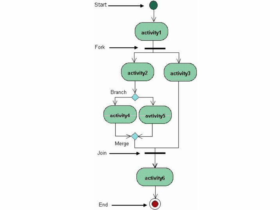
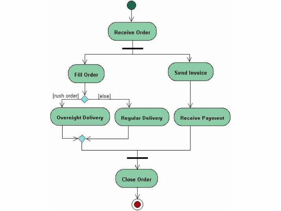
How to draw activity diagram
• Activity diagrams show the flow of activities through the system.
• Diagrams are read from top to bottom and have branches and forks to describe conditions and parallel activities.
• A fork is used when multiple activities are occurring at the same time
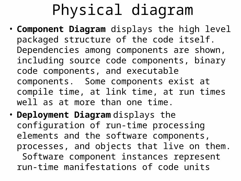
Physical diagram• Component Diagram displays the high level
packaged structure of the code itself. Dependencies among components are shown, including source code components, binary code components, and executable components. Some components exist at compile time, at link time, at run times well as at more than one time.
• Deployment Diagram displays the configuration of run-time processing elements and the software components, processes, and objects that live on them. Software component instances represent run-time manifestations of code units
Where to use physical diagram
• Physical diagrams are used when development of the system is complete.
• Physical diagrams are used to give descriptions of the physical information about a system
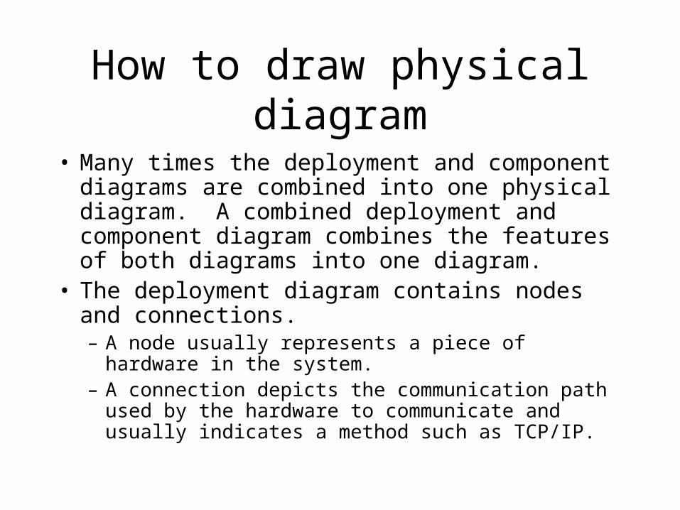
How to draw physical diagram
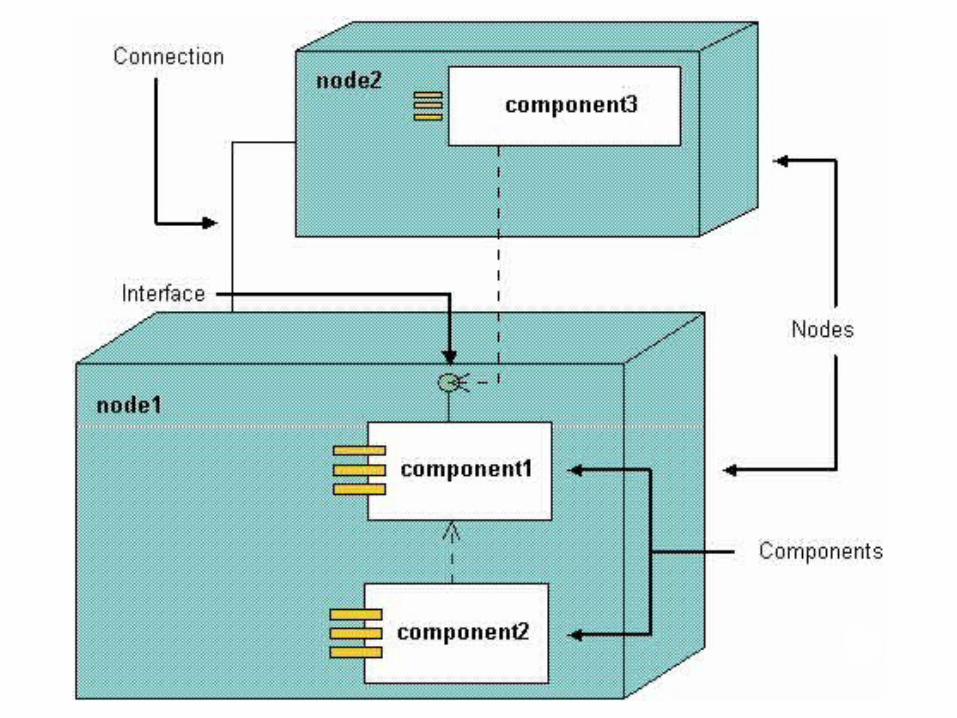
• Many times the deployment and component diagrams are combined into one physical diagram. A combined deployment and component diagram combines the features of both diagrams into one diagram.
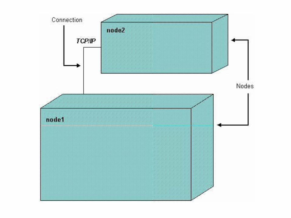
• The deployment diagram contains nodes and connections. – A node usually represents a piece of hardware in the
system. – A connection depicts the communication path used by
the hardware to communicate and usually indicates a method such as TCP/IP.
Component diagram• The component diagram contains components and
dependencies– Components represent the physical packaging of a
module of code. – The dependencies between the components show how
changes made to one component may affect the other components in the system.
– Dependencies in a component diagram are represented by a dashed line between two or more components.
• Component diagrams can also show the interfaces used by the components to communicate to each other