object oriented analysis and design diagrams •uml 2 supports 13 different types of diagrams...
TRANSCRIPT

1
DEPARTMENT OF INFORMATION TECHNOLOGY
OBJECT ORIENTED ANALYSIS AND DESIGN
B Tech III Year II Semester (JNTUH-R15)
Prepared
by
Mr. E.Sunil Reddy.
INSTITUTE OF AERONAUTICAL ENGINEERING (Autonomous)
Dundigal, Hyderabad - 500 043
2 2
UNIT-I
Introduction to UML
3 3
What is the UML?
• “The Unified Modeling Language is a family of
graphical notations, backed by a single meta-model, that
help in describing and designing software systems,
particularly software systems built using the object-
oriented style.”
• UML first appeared in 1997
• UML is standardized. Its content is controlled by the
Object Management Group (OMG), a consortium of
companies.
4 4
What is the UML?
• Unified
– UML combined the best from object-oriented
software modeling methodologies that were in
existence during the early 1990’s.
– Grady Booch, James Rumbaugh, and Ivor Jacobson
are the primary contributors to UML.

5 5
What is the UML? • Modeling
– Used to present a simplified view of reality in order to
facilitate the design and implementation of object-
oriented software systems.
– All creative disciplines use some form of modeling as
part of the creative process.
– UML is a language for documenting design
– Provides a record of what has been built.
– Useful for bringing new programmers up to speed.
6
Chapter 1. Why We Model In this chapter
The importance of modeling
· Four principles of modeling
· Object-oriented modeling

7
Importance of modeling :
A model is a simplification of reality.
We build models so that we can better understand the
system we are developing.
Through modeling, we achieve four aims
1. Models help us to visualize a system as it is or as we
want it to be.
2. Models permit us to specify the structure or behavior
of a system.
3. Models give us a template that guides us in
constructing a system.
4. Models document the decisions we have made.

Principles of Modeling
8
· Four principles of modeling:
1. The choice of what models to create has a profound
influence on how a problem is attacked and how a
solution is shaped.
2. Every model may be expressed at different levels of
precision.
3. The best models are connected to reality.
4. No single model is sufficient. Every nontrivial system is
best approached through a small set of nearly
independent models.

9 9
A Conceptual Model of the UML
• A conceptual model needs to be formed by an individual
to understand UML.
• UML contains three types of building blocks: things,
relationships, and diagrams.
• Things
– Structural things
• Classes, interfaces, collaborations, use cases,
components, and nodes.
– Behavioral things
• Messages and states.

10 10
A Conceptual Model of the UML – Grouping things
• Packages
– Annotational things
• Notes
• Relationships: dependency, association, generalization
and realization.
• Diagrams: class, object, use case, sequence, collaboration,
statechart, activity, component and deployment.
Conceptual Model of the UML
11
Building Blocks of the UML:
The vocabulary of the UML encompasses three kinds of
building blocks:
1. Things
2. Relationships
3. Diagrams
Conceptual Model of the UML
• Things in the UML
• There are four kinds of things in the UML:
• 1. Structural things
• 2. Behavioral things
• 3. Grouping things
• 4. Annotational things
12
Conceptual Model of the UML
• Structural Things
• Structural things are the nouns of UML models. These
are the mostly static parts of a model, representing
elements that are either conceptual or physical. In all,
there are seven kinds of structural things.
• Classes
• Interface
• Cases
• Active Classes
• Components
• Nodes
• Collaborations 13
Conceptual Model of the UML
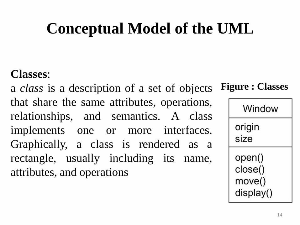
14
Figure : Classes
Classes:
a class is a description of a set of objects
that share the same attributes, operations,
relationships, and semantics. A class
implements one or more interfaces.
Graphically, a class is rendered as a
rectangle, usually including its name,
attributes, and operations
Conceptual Model of the UML
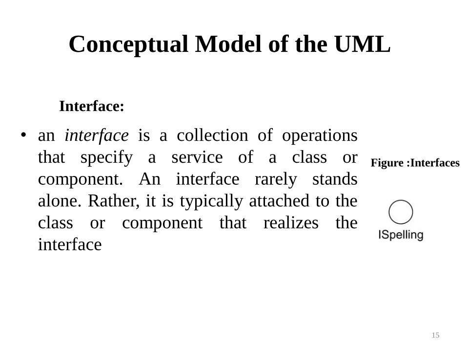
• an interface is a collection of operations
that specify a service of a class or
component. An interface rarely stands
alone. Rather, it is typically attached to the
class or component that realizes the
interface
15
Interface:
Figure :Interfaces
Conceptual Model of the UML
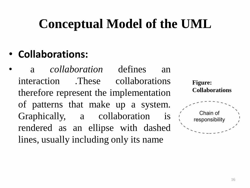
• Collaborations:
• a collaboration defines an
interaction .These collaborations
therefore represent the implementation
of patterns that make up a system.
Graphically, a collaboration is
rendered as an ellipse with dashed
lines, usually including only its name
16
Figure:
Collaborations
Conceptual Model of the UML
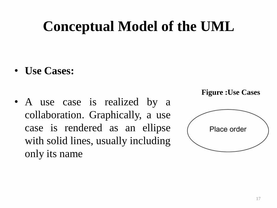
• Use Cases:
• A use case is realized by a
collaboration. Graphically, a use
case is rendered as an ellipse
with solid lines, usually including
only its name
17
Figure :Use Cases
Conceptual Model of the UML
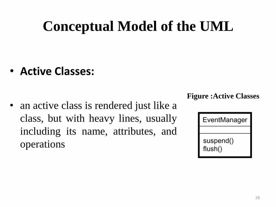
• Active Classes:
• an active class is rendered just like a
class, but with heavy lines, usually
including its name, attributes, and
operations
18
Figure :Active Classes
Conceptual Model of the UML
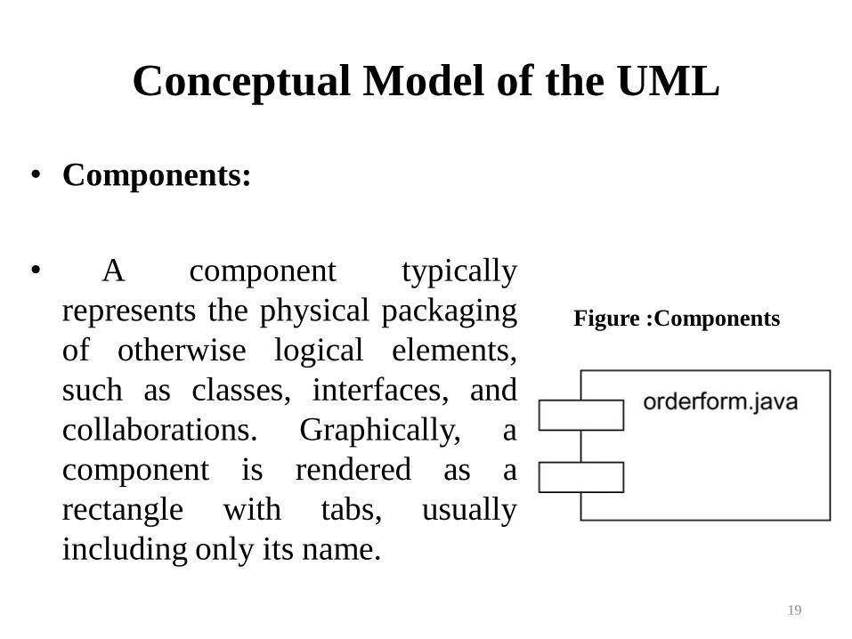
• Components:
• A component typically
represents the physical packaging
of otherwise logical elements,
such as classes, interfaces, and
collaborations. Graphically, a
component is rendered as a
rectangle with tabs, usually
including only its name.
19
Figure :Components

Conceptual Model of the UML
• Nodes:
• a node is a physical element that
exists at run time and represents a
computational resource, generally
having at least some memory and,
often, processing capability. A set of
components may reside on a node
and may also migrate from node to
node. Graphically, a node is rendered
as a cube, usually including only its
name. 20
Figure :Nodes

Conceptual Model of the UML
Behavioral Things:
Behavioral things are the dynamic parts of UML
models. These are the verbs of a model, representing
behavior over time and space. In all, there are two
primary kinds of behavioral things.
1. Messages
2. States
21

Conceptual Model of the UML
• Messages:
• an interaction is a behavior that comprises a set of
messages exchanged among a set of objects within a
particular context to accomplish a specific purpose.
Graphically, a message is rendered as a directed line,
almost always including the name of its operation.
• States:
• a state machine is a behavior that specifies the sequences
of states an object or an interaction goes through during
its lifetime in response to events, together with its
responses to those events.
22
Conceptual Model of the UML
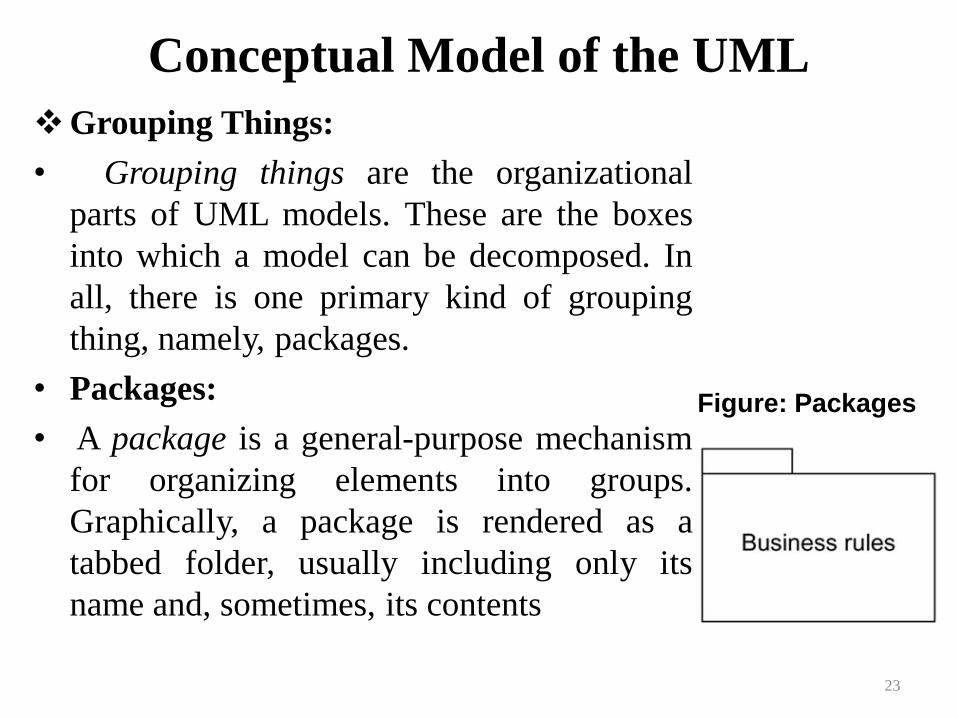
Grouping Things:
• Grouping things are the organizational
parts of UML models. These are the boxes
into which a model can be decomposed. In
all, there is one primary kind of grouping
thing, namely, packages.
• Packages:
• A package is a general-purpose mechanism
for organizing elements into groups.
Graphically, a package is rendered as a
tabbed folder, usually including only its
name and, sometimes, its contents
23
Figure: Packages
24 24
What is the UML?
• Language
– UML is primarily a graphical language that follows a
precise syntax.
– UML 2 is the most recent version
– UML is standardized. Its content is controlled by the
Object Management Group (OMG), a consortium of
companies.
Conceptual Model of the UML
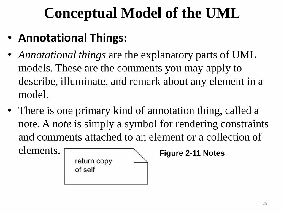
• Annotational Things:
• Annotational things are the explanatory parts of UML
models. These are the comments you may apply to
describe, illuminate, and remark about any element in a
model.
• There is one primary kind of annotation thing, called a
note. A note is simply a symbol for rendering constraints
and comments attached to an element or a collection of
elements.
25
Figure 2-11 Notes
26 26
How We Got to the UML
• OO modeling languages made their appearance in the late
70’s. Smalltalk was the first widely used OO language.
• As the usefulness of OO programming became
undeniable, more OO modeling languages began to
appear.
• By the start of the 90’s there was a flood of modeling
languages, each with its own strengths and weaknesses.
27 27
How We Got to the UML
• In 1994 the UML effort officially began as a
collaborative effort between Booch and Rumbaugh.
Jacobson was soon after included in the effort.
• The goal of UML is to be a comprehensive modeling
language (all things to all people) that will facilitate
communication between all members of the development
effort.
28 28
UML Diagrams
• UML 2 supports 13 different types of diagrams
• Each diagram may be expressed with varying degrees of
detail
• Not all diagrams need be used to model a SW system
• The UML does not offer an opinion as to which diagrams
would be most helpful for a particular type of project
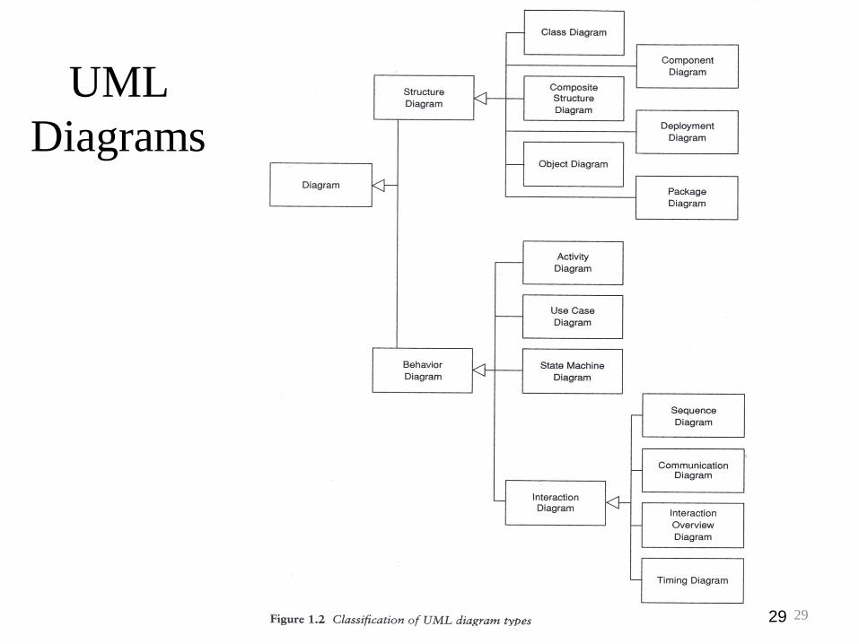
29 29
UML
Diagrams
30 30
What is Legal UML?
• Even though UML is standardized by the OMG
developers will take liberties with syntax.
• These “liberties” have a way of becoming standard
conventions in later releases of the language.
• The same holds true for natural languages.

31 31
The UML is not Enough
Even if the UML is your primary modeling language,
don’t hesitate to use other diagrams to model your
design.
32 32
Architecture
• Architecture refers to the different perspectives from
which a complex system can be viewed.
• The architecture of a software-intensive system is best
described by five interlocking views:
– Use case view: system as seen by users, analysts and
testers.
– Design view: classes, interfaces and collaborations that
make up the system.
– Process view: active classes (threads).
– Implementation view: files that comprise the system.
– Deployment view: nodes on which SW resides.
33 33
Software Development Life Cycle
• UML is involved in each phase of the software
development life cycle.
• The UML development process is
– Use case driven
– Architecture-centric
– Iterative and incremental

UNIT-II
Basic structural modeling
Advanced structural modeling
Class and object diagram
34
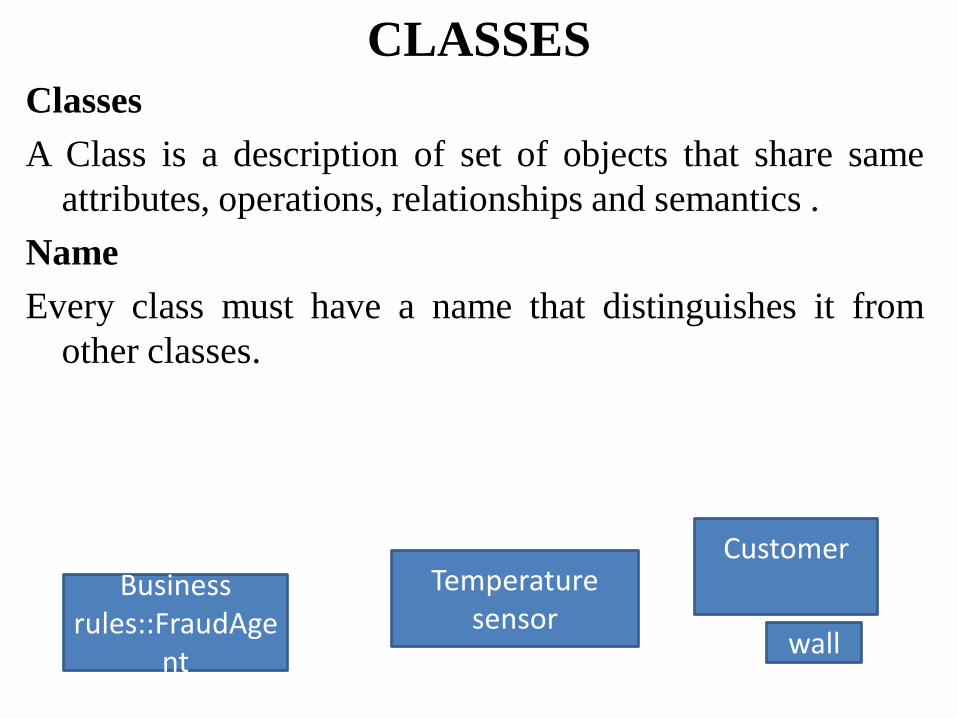
CLASSES Classes
A Class is a description of set of objects that share same
attributes, operations, relationships and semantics .
Name
Every class must have a name that distinguishes it from
other classes.
Temperature sensor
Customer
wall
Business rules::FraudAge
nt

Attributes
-an attribute is a named property of a class that
describes range of values that instances of the
property may hold.
Eg:
Customer Name
Address Phone
Birthdate
wall Height:float Width :float
Thickness:float Isloadbearing
:boolean=false
Attributes and their classes
Attributes

Operations
-An operation is the implementation of a service that can be
requested from any object of the class to affect behavior
.
Rectangle
Add() Grow() Move()
Isempty()
Eg operation
Temperature sensor

Organizing attributes and relationships
-To better organize long lists of attributes and operations
you prefix each group with descriptive category by
using stereotypes .
Fraud agent <<constructor>>
New() New(p:policy
) <<process>> Process(o:or
der)
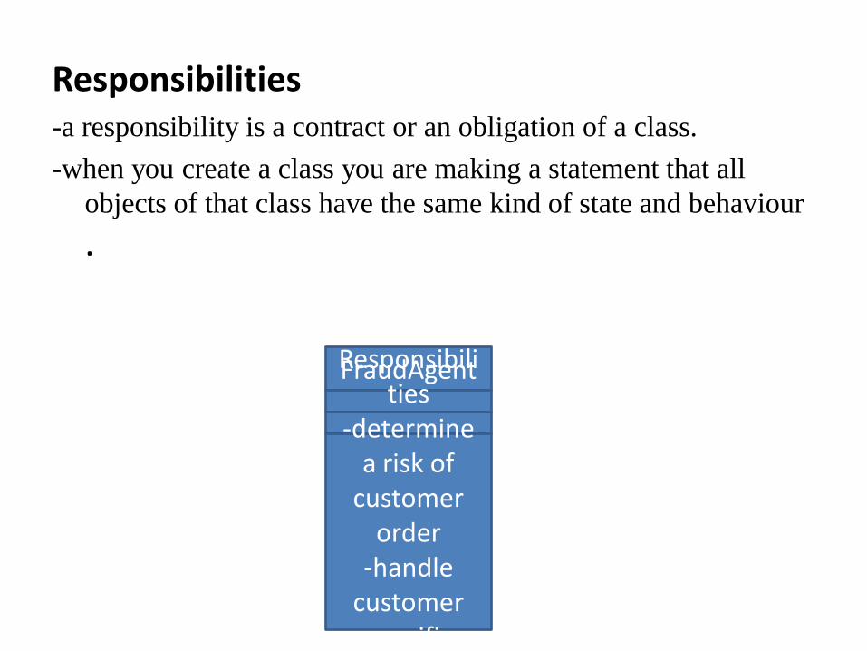
Responsibilities -a responsibility is a contract or an obligation of a class.
-when you create a class you are making a statement that all
objects of that class have the same kind of state and behaviour
.
FraudAgent Responsibilities
-determine a risk of
customer order
-handle customer specific criteria

Common modeling techniques
-Modeling the vocabulary of a system
To model the vocabulary of a system
1) Identify those things that users to describe the problem
.use crc cards and usecase based analysis to help find
these abstractions.
Customer Name Addres
s Phone
BirthDate
Transaction
Action Commit() Rollback(
) Wassuccessfull()

Modeling the vocabulary of a system
contd…. 2)For each abstraction, identify a set of responsibilities.
Make sure that each class is crisply defined and that
there is a good balance of responsibilities among all your
classes.
3)Provide the attributes and operations that are needed to
carry out these responsibilities for each class
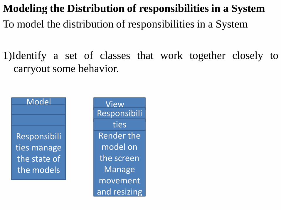
Modeling the Distribution of responsibilities in a System
To model the distribution of responsibilities in a System
1)Identify a set of classes that work together closely to
carryout some behavior.
Model
Responsibilities manage the state of the models
View Responsibili
ties Render the model on the screen
Manage movement and resizing of the view

Modeling the Distribution of responsibilities
in a System contd…
2)Identify a set of responsibilities for each of these classes.
3)Look at this set of classes as a whole, split classes that
have too many responsibilities into smaller abstractions,
collapse tiny classes that have trivial responsibilities into
larger ones, and reallocate responsibilities so that each
abstraction reasonably stands on its own.
4)Consider the ways in which those classes collaborate
with one another, and redistribute their responsibilities
accordingly so that no class within a collaboration does
too much or too little.

Modeling Non software things
1)Model the thing you are abstracting as a class.
2)If you want to distinguish these things from the uml
defined building blocks, create new building block by
using stereotype to specify these new semantics and
to give a distinctive
Visual cue.
Accounts
receivable Agent
Robot
Processorder() Changeorder()
Status()

Modeling Nonsoftware things
contd…
3) If the thing you are modeling is some kind of
hardware that itself contains software, consider
modeling it as a kind of node, as well, so that you can
further expand on its structure.
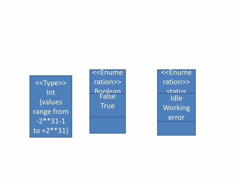
<<Type>> Int
{values range from -2**31-1
to +2**31}
<<Enumeration>> Boolean
False True
<<Enumeration>>
status Idle
Working error

2) If you need to specify the range of values associated with this
type, use constraints.
Modeling Primitive Types contd…

Relationships • A relationship is a connection among things. In
object-oriented modeling, the three most important relationships are dependencies, generalizations, and associations.
• Graphically, a relationship is rendered as a path, with different kinds of lines used to distinguish the kinds of relationships.
48
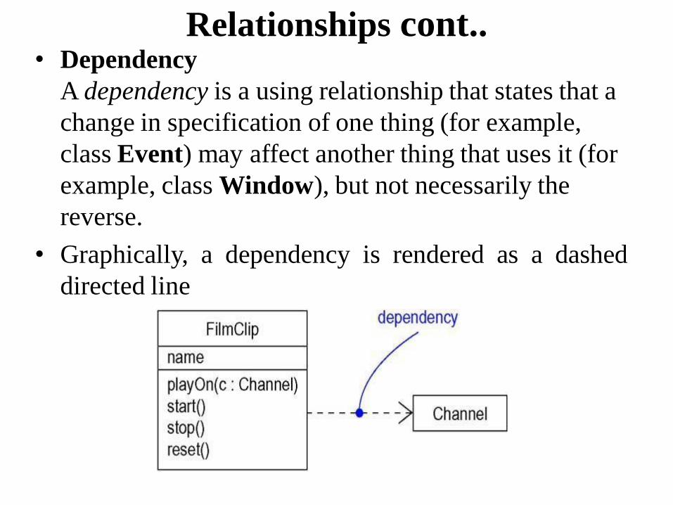
Relationships cont..
• Dependency
A dependency is a using relationship that states that a
change in specification of one thing (for example,
class Event) may affect another thing that uses it (for
example, class Window), but not necessarily the
reverse.
• Graphically, a dependency is rendered as a dashed
directed line
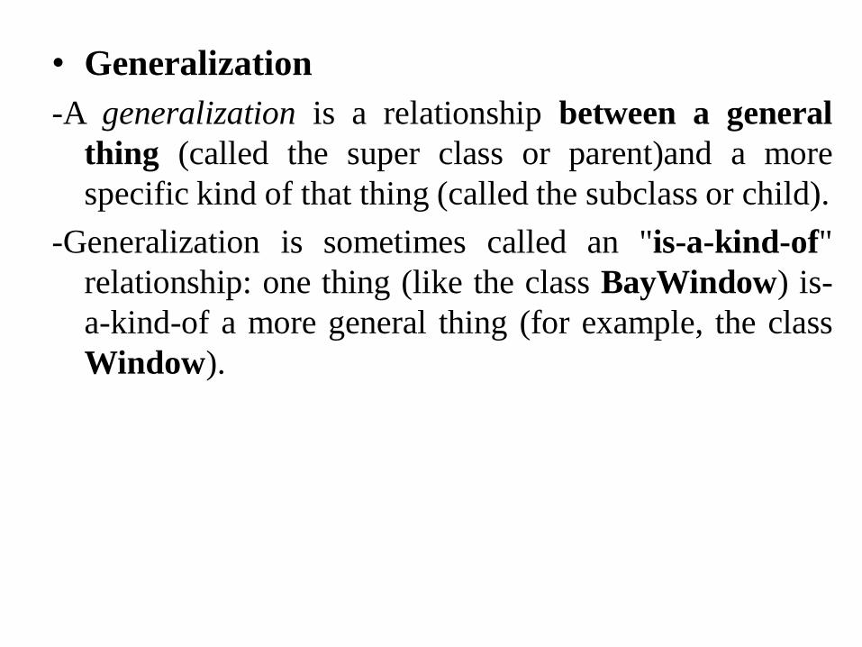
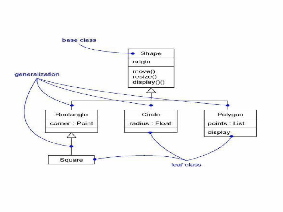
• Generalization
-A generalization is a relationship between a general
thing (called the super class or parent)and a more
specific kind of that thing (called the subclass or child).
-Generalization is sometimes called an "is-a-kind-of"
relationship: one thing (like the class BayWindow) is-
a-kind-of a more general thing (for example, the class
Window).

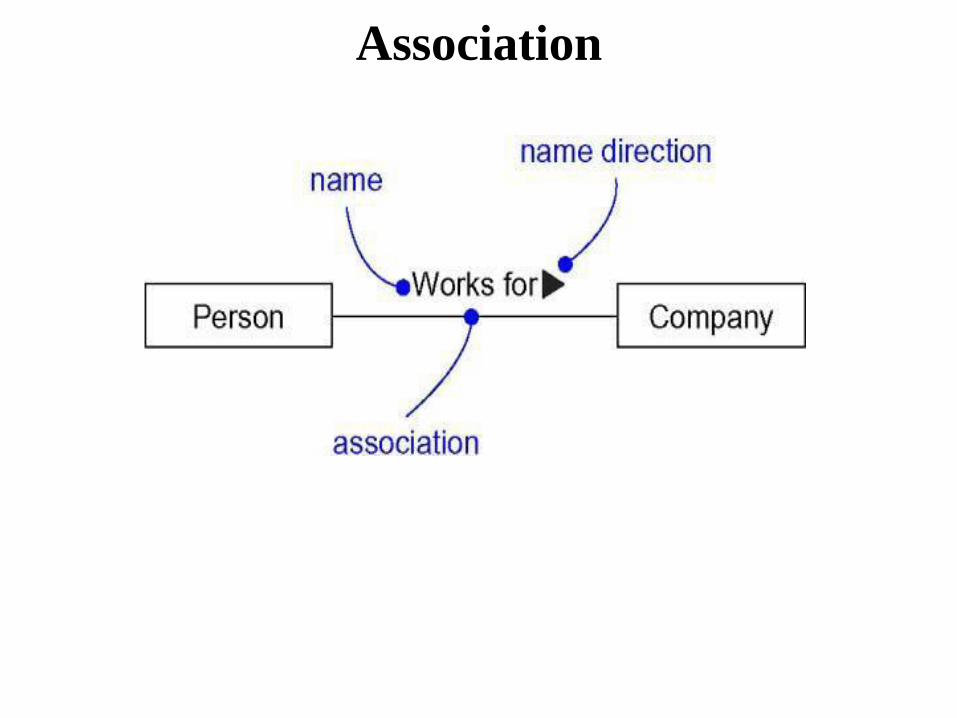
• Association
-An association is a structural relationship that
specifies that objects of one thing are connected to
objects of another. Given an association connecting
two classes, you can navigate from an object of one
class to an object of the other class, and vice versa.
-An association that connects exactly two classes is
called a binary association. Although it's not as
common, you can have associations that connect
more than two classes; these are called n-ary
associations. Graphically, an association is
rendered as a solid line connecting the same or
different classes. Use associations when you want to
show structural relationships.

Association contd…
There are four adornments that apply to associations
Name
- An association can have a name, and you use that
name to describe the nature of the relationship. So
that there is no ambiguity about its meaning, you can
give a direction to the name by providing a direction
triangle that points in the direction you intend to read
the name, as shown in Figure
Association

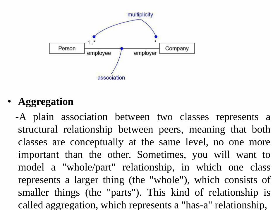
• Multiplicity
-An association represents a structural relationship
among objects. In many modeling situations, it's
important for you to state how many objects may be
connected across an instance of an association.
- This "how many" is called the multiplicity of an
association's role, and is written as an expression that
evaluates to a range of values or an explicit value as
in Figure
• Aggregation
-A plain association between two classes represents a
structural relationship between peers, meaning that both
classes are conceptually at the same level, no one more
important than the other. Sometimes, you will want to
model a "whole/part" relationship, in which one class
represents a larger thing (the "whole"), which consists of
smaller things (the "parts"). This kind of relationship is
called aggregation, which represents a "has-a" relationship,
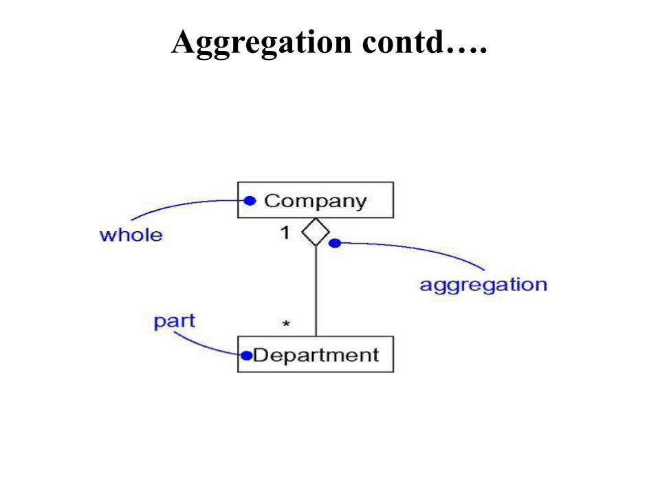
Aggregation contd….
Common Modeling Techniques
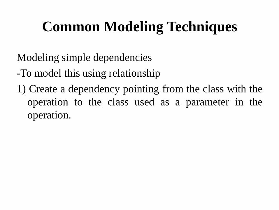
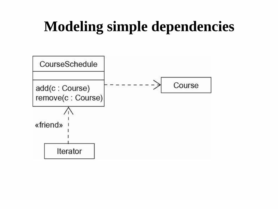
Modeling simple dependencies
-To model this using relationship
1) Create a dependency pointing from the class with the
operation to the class used as a parameter in the
operation.
Modeling simple dependencies
Modeling Single Inheritance
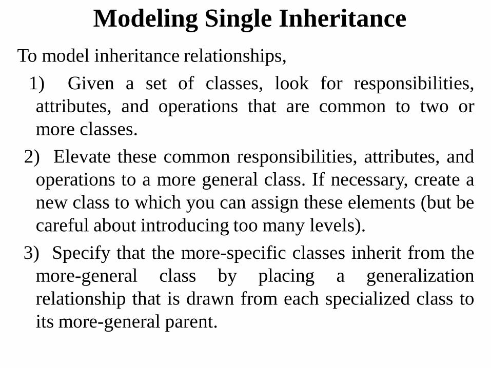
To model inheritance relationships,
1) Given a set of classes, look for responsibilities,
attributes, and operations that are common to two or
more classes.
2) Elevate these common responsibilities, attributes, and
operations to a more general class. If necessary, create a
new class to which you can assign these elements (but be
careful about introducing too many levels).
3) Specify that the more-specific classes inherit from the
more-general class by placing a generalization
relationship that is drawn from each specialized class to
its more-general parent.
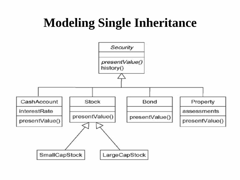
Modeling Single Inheritance
Modeling Structural Relationships
• To model structural relationships,
1)For each pair of classes, if you need to navigate from
objects of one to objects of another, specify an
association between the two. This is a data-driven
view of associations.
2) For each pair of classes, if objects of one class need
to interact with objects of the other class other than as
parameters to an operation, specify an association
between the two. This is more of a behavior-driven
view of associations.
Modeling Structural Relationships
contd….
3) For each of these associations, specify a multiplicity
(especially when the multiplicity is not *, which is the
default), as well as role names (especially if it helps to
explain the model).
4) If one of the classes in an association is structurally or
organizationally a whole compared with the classes at
the other end that look like parts, mark this as an
aggregation by adorning the association at the end near
the whole

Modeling Structural Relationships
contd….
. A note is a graphical symbol for rendering constraints or
comments attached to an element or a collection of elements.
Graphically, a note is rendered as a rectangle with a dog-
eared corner, together with a textual or graphical comment.
A stereotype is an extension of the vocabulary of the UML,
allowing you to create new kinds of building blocks similar
to existing ones but specific to your problem. Graphically, a
stereotype is rendered as a name enclosed by guillemets and
placed above the name of another element. As an option, the
stereotyped element may be rendered by using a new icon
associated with that stereotype.
Modeling Structural Relationships
contd…. • A tagged value is an extension of the properties of a
UML element, allowing you to create new information in
that element's specification. Graphically, a tagged value is
rendered as a string enclosed by brackets and placed
below the name of another element.
A constraint is an extension of the semantics of a UML
element, allowing you to add new rules or to modify
existing ones. Graphically, a constraint is rendered as a
string enclosed by brackets and placed near the
associated element or connected to that element or
elements by dependency relationships. As an alternative,
you can render a constraint in a note.
Modeling Structural Relationships
contd….
• Notes
• A note that renders a comment has no semantic
impact, meaning that its contents do not alter the
meaning of the model to which it is attached. This is
why notes are used to specify things like
requirements, observations, reviews, and
explanations, in addition to rendering constraints.

Other Adornments -Adornments are textual or graphical items that are added to an
element's basic notation and are used to visualize details from
the element's specification.
- For example, the basic notation for an association is a line, but
this may be adorned with such details as the role and
multiplicity of each end.
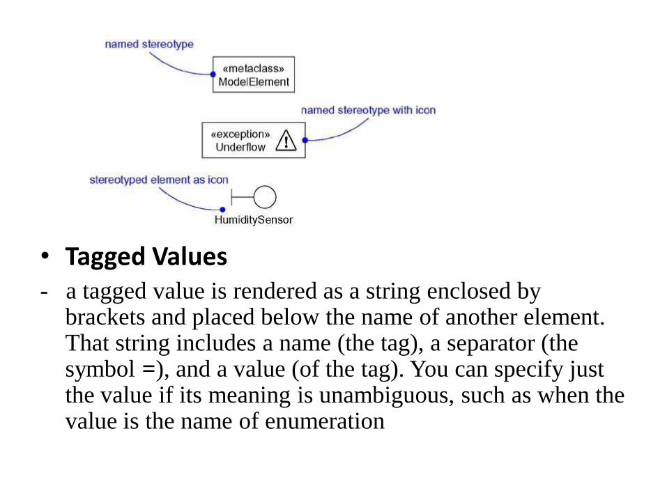
• Tagged Values - a tagged value is rendered as a string enclosed by
brackets and placed below the name of another element. That string includes a name (the tag), a separator (the symbol =), and a value (of the tag). You can specify just the value if its meaning is unambiguous, such as when the value is the name of enumeration

Tagged Values

Documentation
- Specifies a comment, description, or explanation of
the element to which it
is attached.
Common Modeling Techniques
Modeling Comments
• To model a comment
1) Put your comment as text in a note and place it
adjacent to the element to which it refers. You can
show a more explicit relationship by connecting a
note to its elements using a dependency relationship.
Modeling Comments
2) Remember that you can hide or make visible the elements of
your model as you see fit. This means that you don't have to
make your comments visible everywhere the elements to
which it is attached are visible. Rather, expose your
comments in your diagrams only insofar as you need to
communicate that information in that context.
3) If your comment is lengthy or involves something richer than
plain text, consider putting your comment in an external
document and linking or embedding that document in a note
attached to your model.
4) As your model evolves, keep those comments that record
significant decisions that cannot be inferred from the model
itself, and unless they are of historic interest discard the
others.
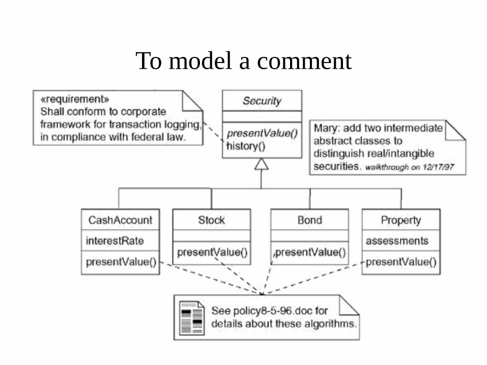
To model a comment

Modeling New Building Blocks
• To model new building blocks,
Make sure there's not already a way to express what you want
by using basic UML. If you have a common modeling
problem, chances are there's already some standard
stereotype that will do what you want.
2) If you're convinced there's no other way to express these
semantics, identify the primitive thing in the UML that's most
like what you want to model (for example, class, interface,
component, node, association, and so on) and define a new
stereotype for that thing. Remember that you can define
hierarchies of stereotypes so that you can have general kinds
of stereotypes along with their specializations (but as with
any hierarchy, use this sparingly).

Modeling New Building Blocks
contd…
3) Specify the common properties and semantics that go
beyond the basic element being stereotyped by
defining a set of tagged values and constraints for the
stereotype.
4) If you want these stereotype elements to have a
distinctive visual cue, define a new icon for the
stereotype.
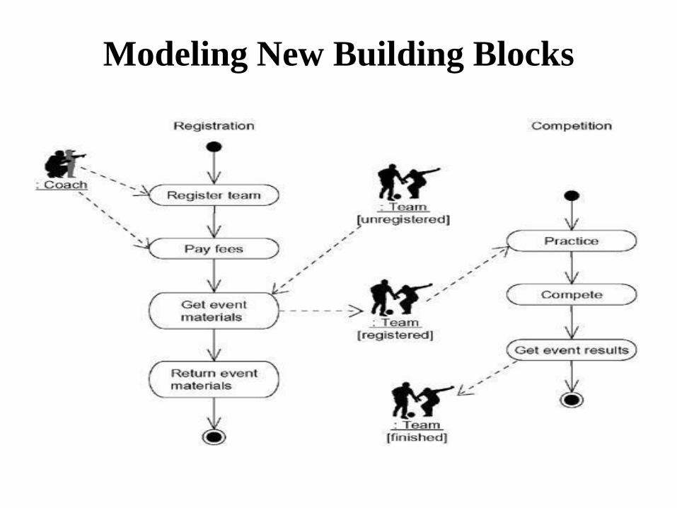
Modeling New Building Blocks
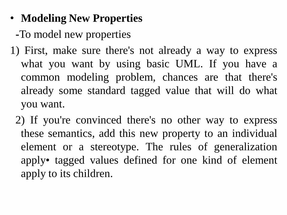
• Modeling New Properties
-To model new properties
1) First, make sure there's not already a way to express
what you want by using basic UML. If you have a
common modeling problem, chances are that there's
already some standard tagged value that will do what
you want.
2) If you're convinced there's no other way to express
these semantics, add this new property to an individual
element or a stereotype. The rules of generalization
apply• tagged values defined for one kind of element
apply to its children.
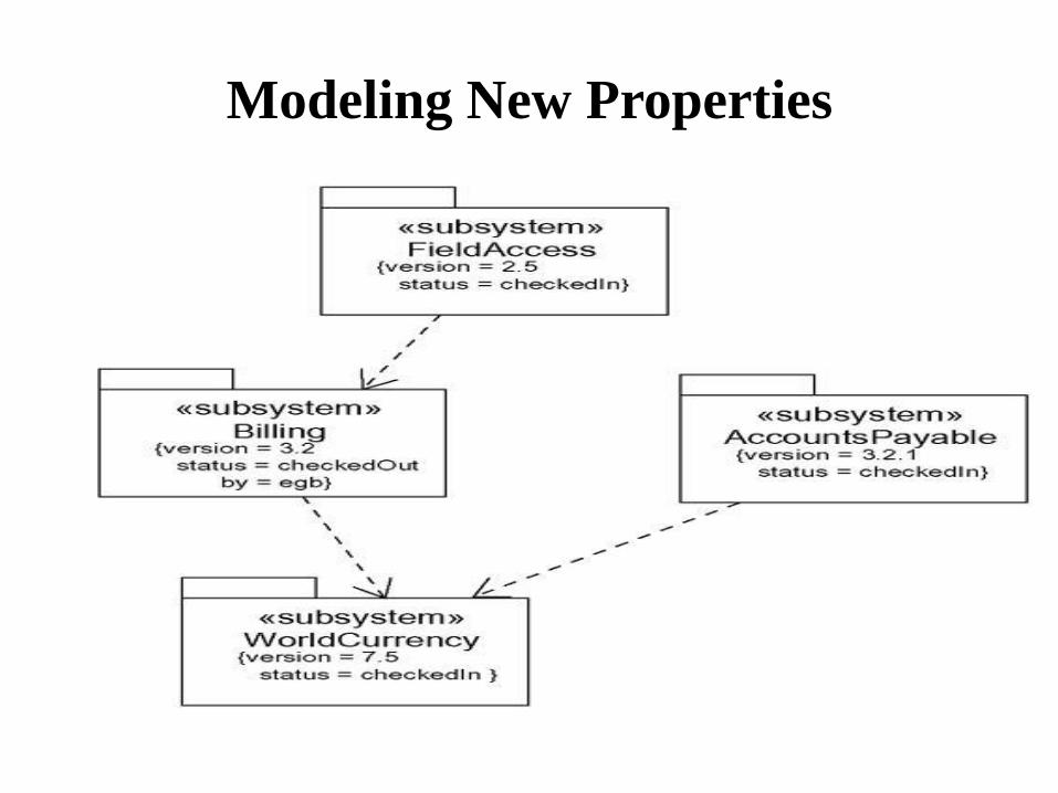
Modeling New Properties
Modeling New Semantics
• To model new semantics,
1) First, make sure there's not already a way to express what
you want by using basic UML. If you have a common
modeling problem, chances are that there's already some
standard constraint that will do what you want.
2) If you're convinced there's no other way to express these
semantics, write your new semantics as text in a constraint
and place it adjacent to the element to which it refers. You
can show a more explicit relationship by connecting a
constraint to its elements using a dependency relationship.
3) If you need to specify your semantics more precisely and
formally, write your new semantics using OCL

Modeling New Semantics

Diagrams
Modeling Different Views of a System
To model a system from different views
1 ) Decide which views you need to best express the
architecture of your system and to expose the technical
risks to your project. The five views of an architecture
described earlier are a good starting point.
2) For each of these views, decide which artifacts you need
to create to capture the essential details of that view. For
the most part, these artifacts will consist of various UML
diagrams.
Modeling Different Views of a System
contd… 3)As part of your process planning, decide which of these
diagrams you'll want to put under some sort of formal or
semi-formal control. These are the diagrams for which
you'll want to schedule reviews and to preserve as
documentation for the project.
4) Allow room for diagrams that are thrown away. Such
transitory diagrams are still useful for exploring the
implications of your decisions and for experimenting
with changes.

Modeling Different Views of a System
-Use case view
Use case diagrams
Activity diagrams (for behavioral modeling)
- Design view
Class diagrams (for structural modeling) Interaction diagrams (for
behavioral
modeling)
Statechart diagrams (for behavioral modeling)
-Process view
Class diagrams (for structural modeling) Interaction diagrams (for
behavioral
modeling)
-Implementation view
Component diagram
-Deployment view
Deployment diagrams
Modeling Different Levels of Abstraction
• Consider the needs of your readers, and start with a
given model.
• If your reader is using the model to construct an
implementation, she'll need diagrams that are at a lower
level of abstraction, which means that they'll need to
reveal a lot of detail. If she is using the model to present
a conceptual model to an end user, she'll need diagrams
that are at a higher level of abstraction, which means that
they'll hide a lot of detail.
• Depending on where you land in this spectrum of low-
to-high levels of abstraction, create a diagram at the right
level of abstraction by hiding or revealing the following
four categories of things from your model
– Building blocks and relationships:
Hide those that are not relevant to the intent of your diagram
or the needs of your reader.
Adornments:
Reveal only the adornments of these building blocks and
relationships that are essential to understanding your intent.
– Flow:
In the context of behavioral diagrams, expand only those
messages or transitions that are essential to understanding
your intent.
Stereotypes:
In the context of stereotypes used to classify lists of things,
such as attributes and operations, reveal only those
stereotyped items that are essential to understanding your
intent.
Modeling Different Levels of Abstraction
- To model a system at different levels of abstraction by
creating models at different levels of abstraction
• Consider the needs of your readers and decide on the
level of abstraction that each should view, forming a
separate model for each level.
In general, populate your models that are at a high level of
abstraction with simple abstractions and your models that
are at a low level of abstraction with detailed abstractions.
Establish trace dependencies among the related elements of
different models.

• there are four common situations you'll encounter when
modeling a system at different levels of abstraction:
Use cases and their realization:
Use cases in a use case model will trace to collaborations in a
design model.
Collaborations and their realization:
Collaborations will trace to a society of classes that work
together to carry out the collaboration.
Components and their design:
Components in an implementation model will trace to the
elements in a design model.
Nodes and their components:
Nodes in a deployment model will trace to components in an
implementation model

Figure Interaction Diagram at a High Level of Abstraction
87

Modeling Different Levels of Abstraction Figure Interaction at a Low Level of Abstraction
Modeling Complex Views
• To model complex views,
• First, convince yourself there's no meaningful way
to present this information at a higher level of
abstraction, perhaps eliding some parts of the diagram
and retaining the detail in other parts.
• If you've hidden as much detail as you can and your
diagram is still complex, consider grouping some of
the elements in packages or in higher level
collaborations, then render only those packages or
collaborations in your diagram.

Modeling Complex Views contd…
• If your diagram is still complex, use notes and
color as visual cues to draw the reader's attention
to the points you want to make.
• If your diagram is still complex, print it in its
entire and hang it on a convenient large wall. You
lose the interactivity an online version of the diagram
brings, but you can step back from the diagram and
study it for common patterns.

Advanced Classes
• A classifier is a mechanism that describes structural and
behavioral features.
• Classifiers include classes, interfaces, data types, signals,
components, nodes, use cases, and subsystems.
• The UML provides a number of other kinds of classifiers to
help you model.
• Interface
A collection of operations that are used to specify a
service of a class or a component
• Data type
A type whose values have no identity, including primitive
built-in types (such as numbers and strings), as well as
enumeration types (such as Boolean)
Signal
• The specification of an asynchronous stimulus communicated
between instances
component
• A physical and replaceable part of a system that conforms to and
provides the realization of a set of interfaces
Node
• A physical element that exists at run time and that represents a
computational resource, generally having at least some memory and
often processing capability
Use case
• A description of a set of a sequence of actions, including variants,
that a system performs that yields an observable result of value to a
particular actor
Subsystem
• A grouping of elements of which some constitute a specification of
the behavior offered by the other contained elements
Advanced Classes contd…
Visibility
- UML, you can specify any of three levels of visibility.
1. public
Any outside classifier with visibility to the given
classifier can use the feature specified by prepending
the symbol +.
2. protected
Any descendant of the classifier can use the feature;
specified by prepending the symbol #.
3. private
Only the classifier itself can use the feature; specified
by prepending the symbol.

• Scope
1. instance
• Each instance of the classifier holds its own value
for the feature.
2. classifier
• There is just one value of the feature for all
instances of the classifier.
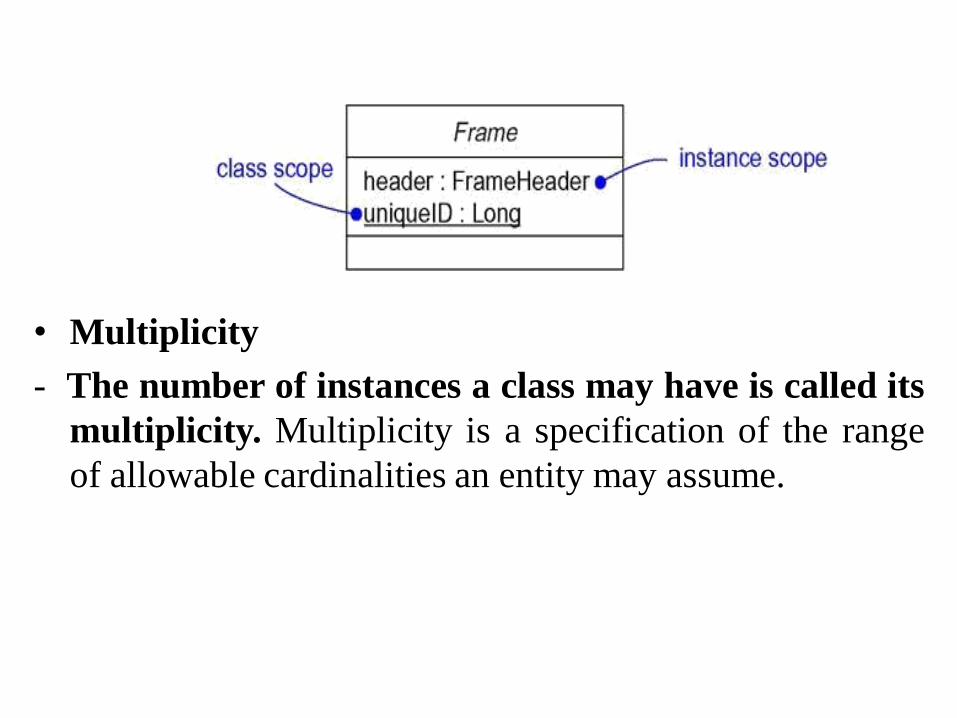
• Multiplicity
- The number of instances a class may have is called its
multiplicity. Multiplicity is a specification of the range
of allowable cardinalities an entity may assume.

• Attributes • In its full form, the syntax of an attribute in the UML is
• [visibility] name [multiplicity] [: type] [= initial-value] [{property-string}]
• There are three defined properties that you can use with
attributes.
1.changeable
2. addOnly
3. frozen
Operations
• In its full form, the syntax of an operation in the UML is
[visibility] name [(parameter-list)] [: return-type] [{property-
string}]
• In an operation's signature, you may provide zero or
more parameters, each of which follows the syntax
• [direction] name : type [= default-value]
• Direction may be any of the following values
1) in
2) out
3) inout
-there are four defined properties that you can use with
operations.
1)IsQuery
2)Sequential
3)Guarded
4)Concurrent
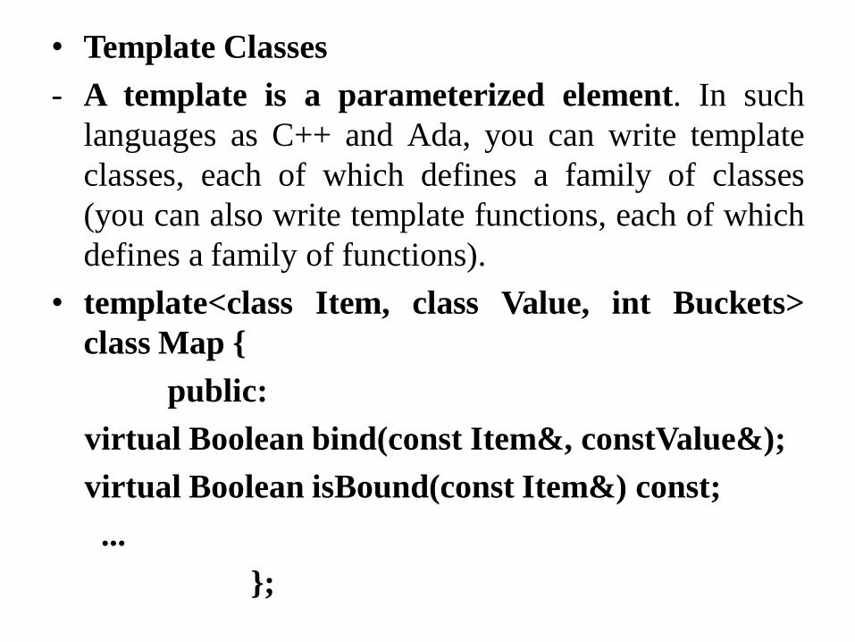
• Template Classes
- A template is a parameterized element. In such
languages as C++ and Ada, you can write template
classes, each of which defines a family of classes
(you can also write template functions, each of which
defines a family of functions).
• template<class Item, class Value, int Buckets>
class Map {
public:
virtual Boolean bind(const Item&, constValue&);
virtual Boolean isBound(const Item&) const;
...
};
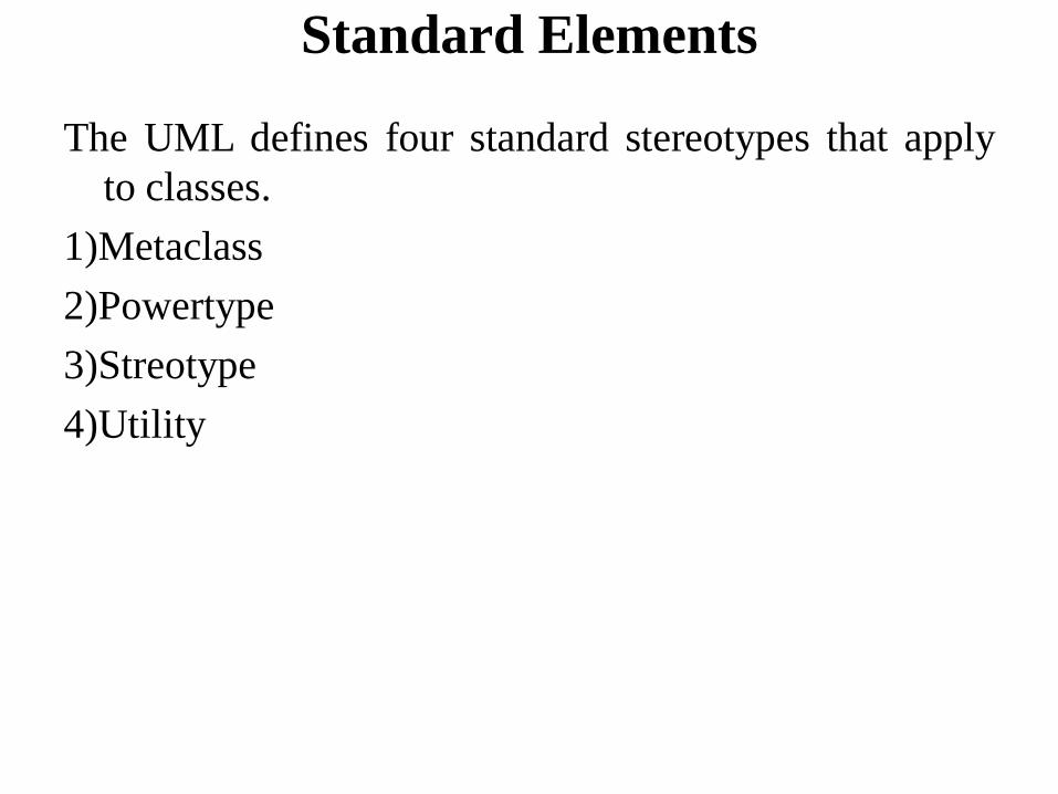
Standard Elements
The UML defines four standard stereotypes that apply
to classes.
1)Metaclass
2)Powertype
3)Streotype
4)Utility
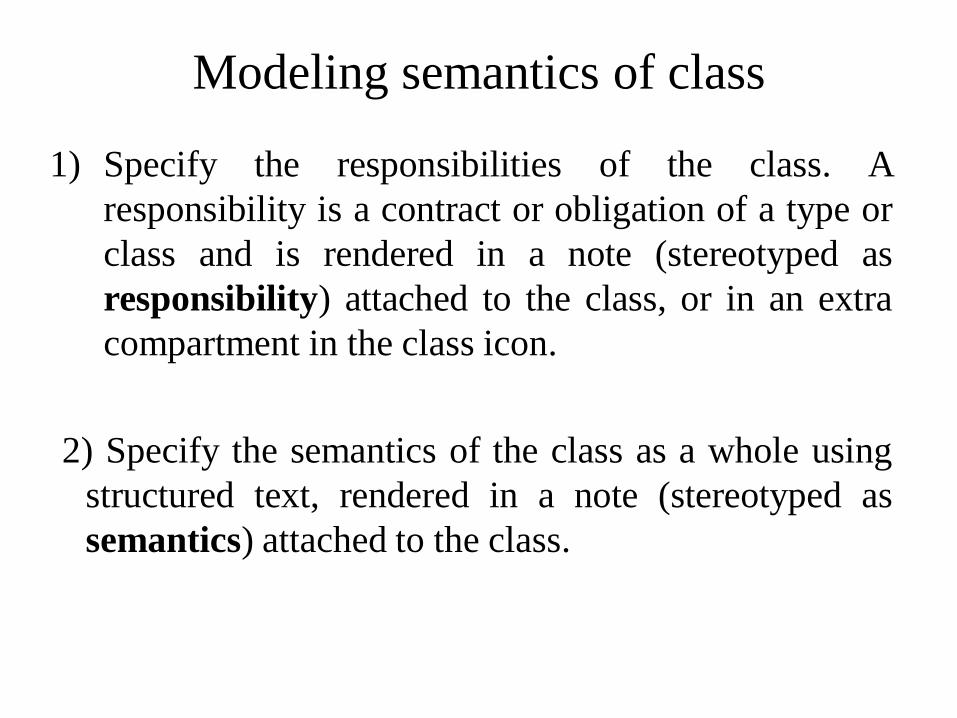
Modeling semantics of class
1) Specify the responsibilities of the class. A
responsibility is a contract or obligation of a type or
class and is rendered in a note (stereotyped as
responsibility) attached to the class, or in an extra
compartment in the class icon.
2) Specify the semantics of the class as a whole using
structured text, rendered in a note (stereotyped as
semantics) attached to the class.

Modeling semantics of class contd…
3) Specify the body of each method using structured text
or a programming language, rendered in a note
attached to the operation by a dependency relationship.
4) Specify the pre- and post conditions of each operation,
plus the invariants of the class as a whole, using
structured text. These elements are rendered in notes
(stereotyped as precondition, post condition, and
invariant) attached to the operation or class by a
dependency relationship.
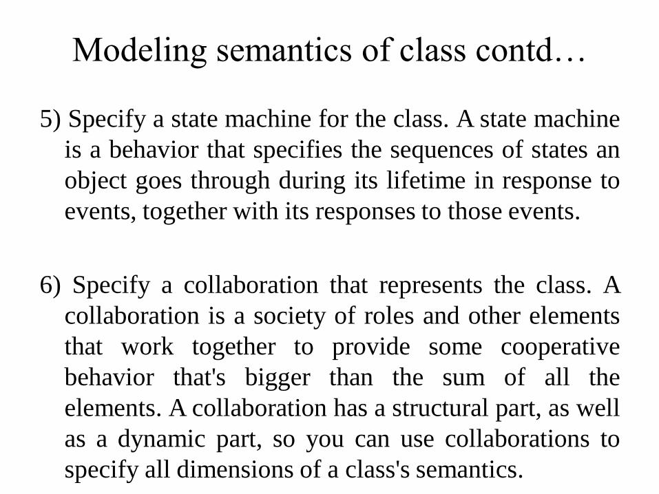
Modeling semantics of class contd…
5) Specify a state machine for the class. A state machine
is a behavior that specifies the sequences of states an
object goes through during its lifetime in response to
events, together with its responses to those events.
6) Specify a collaboration that represents the class. A
collaboration is a society of roles and other elements
that work together to provide some cooperative
behavior that's bigger than the sum of all the
elements. A collaboration has a structural part, as well
as a dynamic part, so you can use collaborations to
specify all dimensions of a class's semantics.

Advanced Relationships
-A relationship is a connection among things. In object-
oriented modeling, the four most important
relationships are dependencies, generalizations,
associations, and realizations.
-Graphically, a relationship is rendered as a path, with
different kinds of lines used to distinguish the
different relationships.
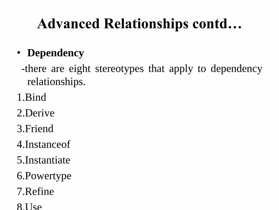
Advanced Relationships contd…
• Dependency
-there are eight stereotypes that apply to dependency
relationships.
1.Bind
2.Derive
3.Friend
4.Instanceof
5.Instantiate
6.Powertype
7.Refine
8.Use

Advanced Relationships contd…
• There are two stereotypes that apply to dependency
relationships among packages.
1)access
2)Import
• There are two stereotypes that apply to dependency
relationships among usecases.
1)Extend
2) Include
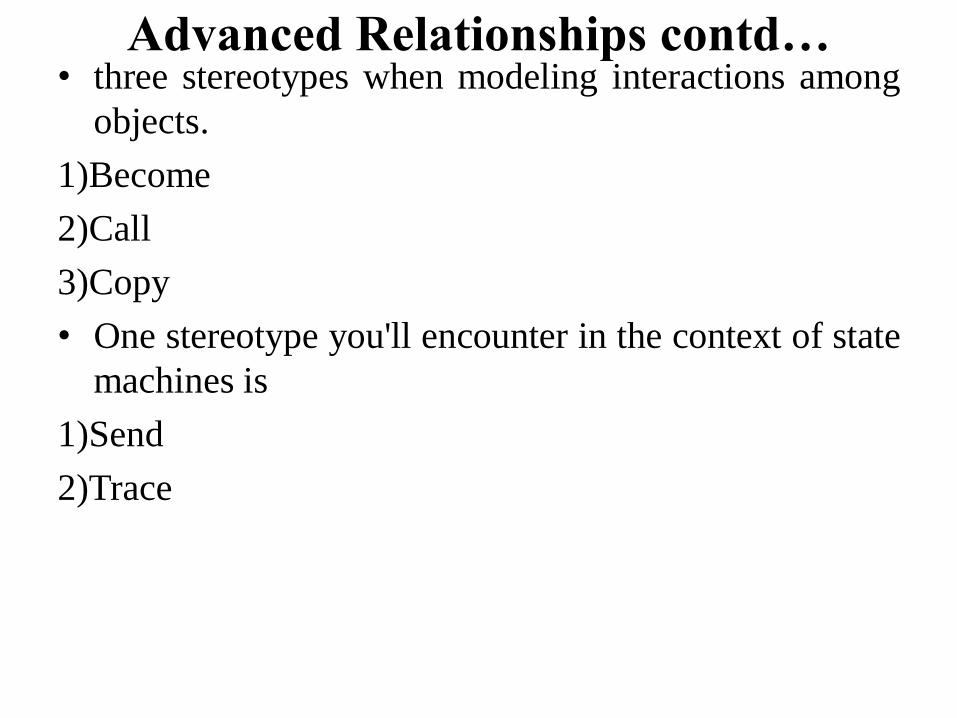
Advanced Relationships contd… • three stereotypes when modeling interactions among
objects.
1)Become
2)Call
3)Copy
• One stereotype you'll encounter in the context of state
machines is
1)Send
2)Trace

Advanced Relationships contd… • Generalization
A generalization is a relationship between a general
thing (called the superclass or parent) and a more
specific kind of that thing (called the subclass or
child).
• The four constraints that may be applied to
generalization relationships.
1.Complete
2.Incomplete
3.Disjoint
4.Overlapping
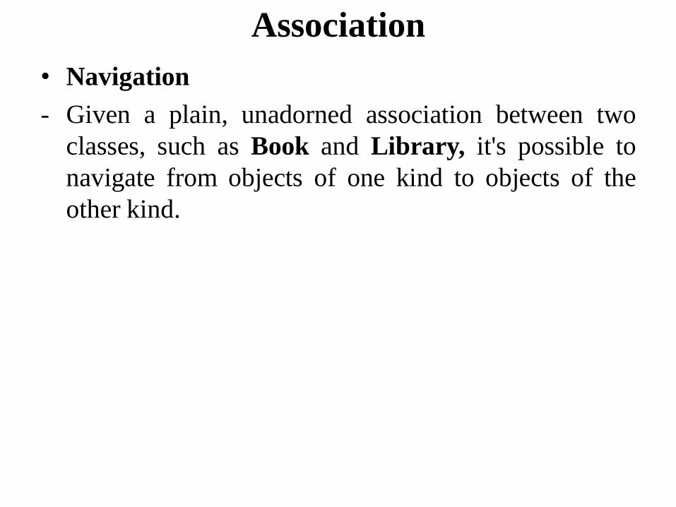
Association
• Navigation
- Given a plain, unadorned association between two
classes, such as Book and Library, it's possible to
navigate from objects of one kind to objects of the
other kind.

• Visibility
- Given an association between two classes, objects of
one class can see and navigate to objects of the other,
unless otherwise restricted by an explicit statement of
navigation
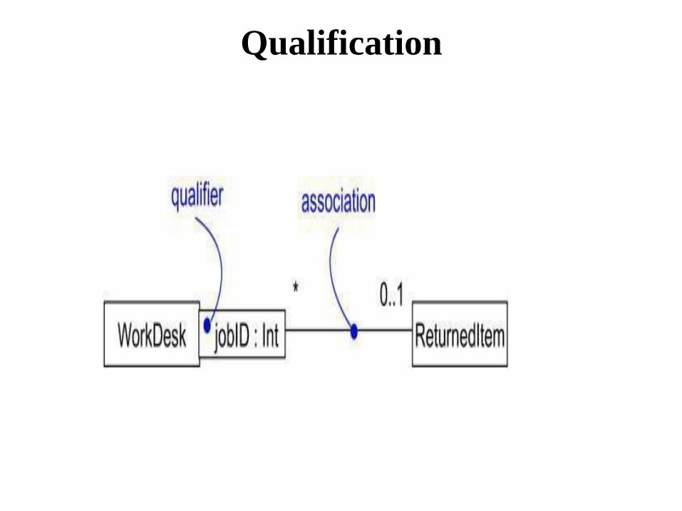
Qualification
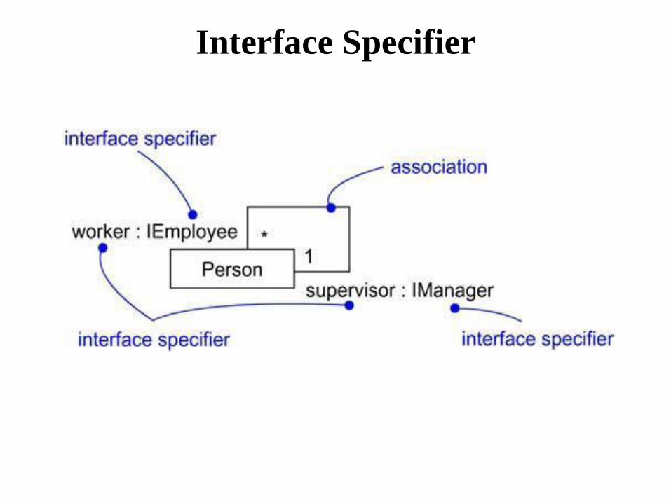
Interface Specifier
• Composition
• Aggregation turns out to be a simple concept with
some fairly deep semantics. Simple aggregation is
entirely conceptual and does nothing more than
distinguish a "whole" from a "part."
• Simple aggregation does not change the meaning of
navigation across the association between the whole
and its parts, nor does it link the lifetimes of the
whole and its parts

Composition
Constraints
1.Implicit
2.Ordered
3.Changable
4.Addonly
5.Frozen
• Realization
• A realization is a semantic relationship between
classifiers in which one classifier specifies a contract
that another classifier guarantees to carry out.
• Common Modeling Techniques
• Modeling Webs of Relationships
• Don't begin in isolation. Apply use cases and
scenarios to drive your discovery of the relationships
among a set of abstractions.
• In general, start by modeling the structural
relationships that are present. These reflect the static
view of the system and are therefore fairly tangible.
• Next, identify opportunities for
generalization/specialization relationships; use
multiple inheritance sparingly.

Modeling Webs of Relationships
• Only after completing the preceding steps should you
look for dependencies; they generally represent more-
subtle forms of semantic connection.
• For each kind of relationship, start with its basic form
and apply advanced features only as absolutely
necessary to express your intent.
• Remember that it is both undesirable and unnecessary
to model all relationships among a set of abstractions in
a single diagram or view. Rather, build up your system's
relationships by considering different views on the
system. Highlight interesting sets of relationships in
individual diagrams.

• An interface is a collection of operations that are used
to specify a service of a class or a component.
• Names
An interface name must be unique within its enclosing
package.
• Operations
An interface is a named collection of operations used
to specify a service of a class or of a component.
• Relationships
Like a class, an interface may participate in
generalization, association, and dependency
relationships.
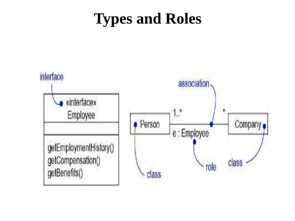
Types and Roles

Common Modeling Techniques
Modeling the Seams in a Systemeling the Seams in a
System
• Within the collection of classes and components in
your system, draw a line around those that tend to be
tightly coupled relative to other sets of classes and
components.
• Refine your grouping by considering the impact of
change. Classes or components that tend to change
together should be grouped together as collaborations.
Modeling the Seams in a Systemeling
the Seams in a System
• Consider the operations and the signals that cross these
boundaries, from instances of one set of classes or components
to instances of other sets of classes and components.
- Package logically related sets of these operations and signals as
interfaces.
• For each such collaboration in your system, identify the
interfaces it relies on (imports) and those it provides to others
(exports). You model the importing of interfaces by
dependency relationships, and you model the exporting of
interfaces by realization relationships.
• For each such interface in your system, document its
dynamics by using pre- and postconditions for each operation,
and use cases and state machines for the interface as a whole.

Modeling Static and Dynamic Types
• To model a dynamic type
• Specify the different possible types of that object by
rendering each type as a class stereotyped as type (if
the abstraction requires structure and behavior) or as
interface (if the abstraction requires only behavior).
• Model all the roles the class of the object may take on
at any point in time. You can do so in two ways:
First, in a class diagram, explicitly type each role that
the class plays in its association with other classes.
Doing this specifies the face instances of that class
put on in the context of the associated object.
Second, also in a class diagram, specify the class-to-
type relationships using generalization.

To model a dynamic type
• In an interaction diagram, properly render each instance
of the dynamically typed class. Display the role of the
instance in brackets below the object's name.
• To show the change in role of an object, render the
object once for each role it plays in the interaction, and
connect these objects with a message stereotyped as
become.
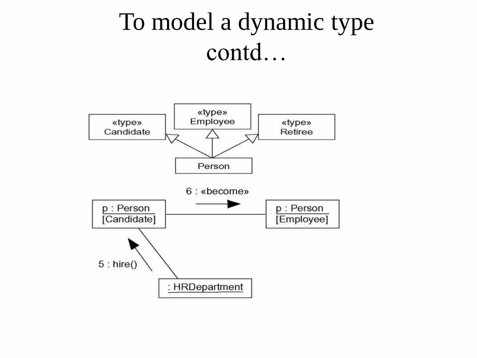
To model a dynamic type
contd…

Packages
• Names
A package name must be unique within its enclosing
package.
Packages contd…
• Owned Elements
-A package may own other elements, including classes,
interfaces, components, nodes, collaborations, use
cases, diagrams, and even other packages.
• Visibility
-You can control the visibility of the elements owned
by a package just as you can control the visibility of
the attributes and operations owned by a class
Packages contd…
• Importing and Exporting
Suppose you have two classes named A and B sitting
side by side. Because they are peers, A can see B and
B can see A, so both can depend on the other. Just
two classes makes for a trivial system, so you really
don't need any kind of packaging.
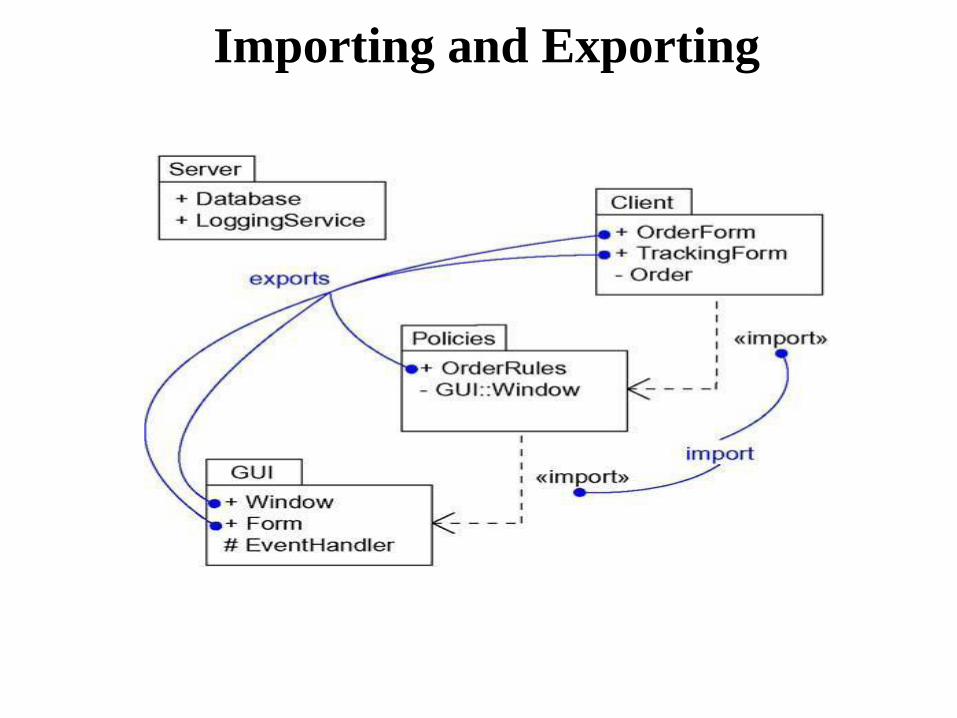
Importing and Exporting

Generalization
• There are two kinds of relationships you can have
between packages: import and access dependencies,
used to import into one package elements exported
from another, and generalizations, used to specify
families of packages.
• Standard Elements
1.Facade
2.Framework
3.Stub
4.Subsytem
5.System
• Common Modeling Techniques
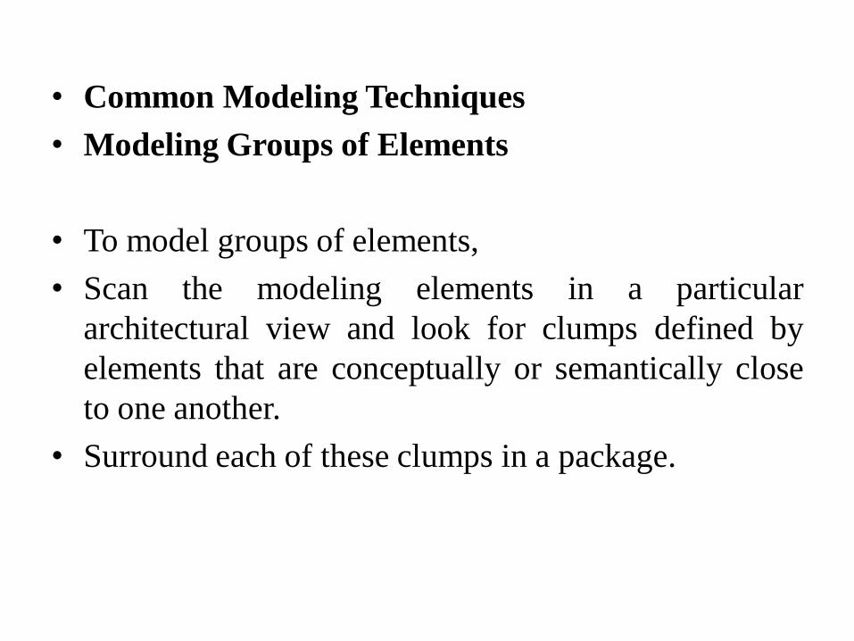
• Modeling Groups of Elements
• To model groups of elements,
• Scan the modeling elements in a particular
architectural view and look for clumps defined by
elements that are conceptually or semantically close
to one another.
• Surround each of these clumps in a package.
Modeling Groups of Elements
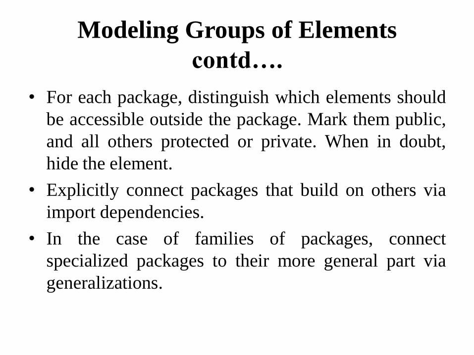
contd….
• For each package, distinguish which elements should
be accessible outside the package. Mark them public,
and all others protected or private. When in doubt,
hide the element.
• Explicitly connect packages that build on others via
import dependencies.
• In the case of families of packages, connect
specialized packages to their more general part via
generalizations.
Modeling Groups of Elements
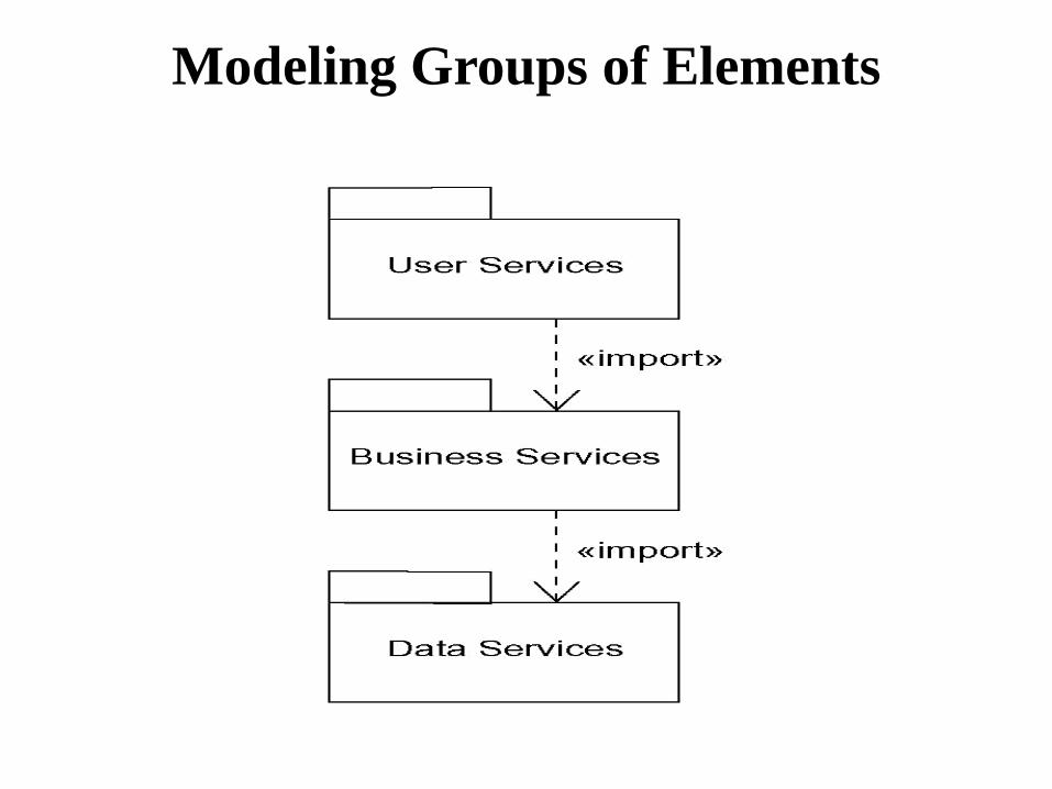
Modeling Architectural Views
• To model architectural views,
• Identify the set of architectural views that are
significant in the context of your problem. In practice,
this typically includes a design view, a process view,
an implementation view, a deployment view, and a
use case view.
• Place the elements (and diagrams) that are necessary
and sufficient to visualize, specify, construct, and
document the semantics of each view into the
appropriate package

Modeling Architectural Views
• As necessary, further group these elements into their
own packages.
• There will typically be dependencies across the
elements in different views. So, in general, let each
view at the top of a system be open to all others at
that level
CLASS AND OBJECT DIAGRAM

Class diagram
Class diagram
• It’s a diagram that shows set of classes ,interfaces
,collaboration and either relationships .
Common properties
• It shows the same common properties as all other
diagrams .
Contents
Class diagram contain the following things
1. Classes
2. Interfaces
3. Collaboration
4. Dependency ,Generalization, association
Common modeling techniques
Modeling simple collaboration
To model a collaboration .
1. Identify the mechanism you want to model .
2. For each mechanism identify the classes ,interfaces
and collaboration .
3. Use scenarios to walk through these things .
4. Be sure to populate these elements with their
contents .
Modeling a logical database schema
To model a schema
1. Identify those classes in the model whose state must
transcend the lifetime of their application.
2. Create class diagram that contain these classes and
mark them as persistent .
3. Explain structural details of these classes .
4. Watch for common pattern that complicate physical
database design .
5. Consider the behavior of these classes by expending
operations .
6. Use tools to transform logical design to physical
design .
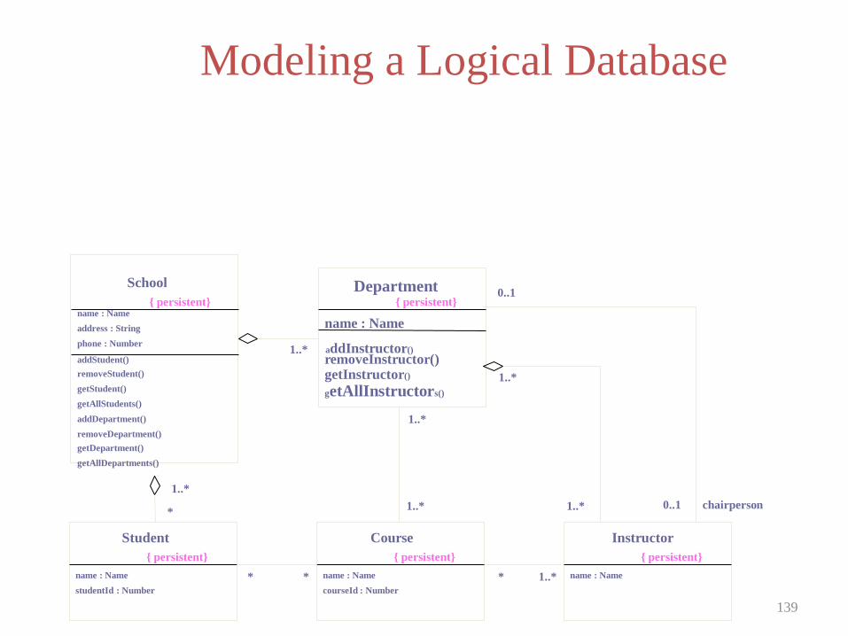
Modeling a Logical Database
139
1..*
School
{ persistent} name : Name
address : String
phone : Number
addStudent()
removeStudent()
getStudent()
getAllStudents()
addDepartment()
removeDepartment()
getDepartment()
getAllDepartments()
Student
{ persistent}
name : Name
studentId : Number
Instructor
{ persistent}
name : Name
Department { persistent}
name : Name
addInstructor()
removeInstructor() getInstructor()
getAllInstructors()
Course
{ persistent}
name : Name
courseId : Number
1..*
1..*
1..*
1..*
1..*
1..* *
0..1
0..1 chairperson
* * *

Forward and Reverse Engineering
Forward Engineering
- It is the process of transforming a model intocode
through a mapping to an implementation language .
To forward engineer a class diagram
1) Identify the rules for mapping to your implentation
language .
2) Depending upon the semsntics of the language you
have to constrain .
3) Use tagged values to specify your tagged values.
4) Use tools to forward engineer your models .
Reverse Engineering
-transforming code to uml model.
To reverse engineer a class diagram
1) Identify the rules for mapping from your language.
2) Use tools point to code you would like to reverse
engineer.
3) Use tool, create a class diagram by querying the
model.

Public abstract class EventHandler
{
EventHandler sucessor;
private Integer CurrentEventId;
private String source;
EventHandler()
{ }
public void handlerequest(){ }
}

Object Diagram
Object diagram
-it is a diagram that shows set of objects and their
relationships at a point in time .
Contents :
-objects
-links
Object diagram contains notes and constraints .
Modeling object structures
To model object structures
1) Identify the mechanism you would like to model.
2) For each mechanism ,identify classes
,interfaces,other elements.
3) Consider one scenario that work through this
mechanism .
4) Expose the state and atrribute value of each such
object to understand .
5) Similarly expose the links ,instances,associationns
among them

Forward and Reverse Engineer
To reverse engineer an object diagram
1) Choose the target you want to reverse engineer.
2) Use tool or simply walkthrough a scenario.
3) Identify the set of objects that collaborate in the
context .
4) As necessary to understand their semantics expose
these objects .
5) Identify links among objects .
6) If your diagrams end up complicated ,prune it by
eliminating objects that are not germane.
UNIT III
BASIC BEHAVIOURAL MODELING-I
BASIC BEHAVIORAL MODELING -II

INTERACTION
An interaction is a behavior that comprises a set of
messages exchanged among a set of objects within a
context to accomplish a purpose. A message is a
specification of a communication between objects
that conveys information with the expectation that
activity will ensue.
CONTEXT
You'll find interactions in the collaboration of objects
that exist in the context of your system or subsystem
Object and Roles :
The object that participate in an interaction is either
concrete or prototypical

LINKS
• A link is a semantic connection among objects.
• In general, a link is an instance of an association.
• Following fig. shows, wherever a class has an
association to another class, there may be a link
between the instances of the two classes; wherever
there is a link between two objects, one object can
send a message to the other object.

LINKS contd…
Link contd….
• Association – corresponding object is visible
by association.
• self - dispatches of operation.
• Global – represents enclosing scope.
• Local – local scope
• Parameter – parameter visibility.
MESSAGE
When you pass a message, the action that results is an executable statement that forms an abstraction of a computational procedure. An action may result in a change in state.
• UML can model several kind of actions:
• call - invoke an operation
• return - return a value to the caller
• send - send signal to an object
• create - creates an object
• destroy - destroys an object
Following figure shows visual distinction among different kind of messages

MESSAGE contd..
SEQUENCING
When an object passes a message to another object (in
effect, delegating some action to the receiver), the
receiving object might in turn send a message to
another object, which might send a message to yet a
different object, and so on. This stream of messages
forms a sequence.

Procedural Sequence
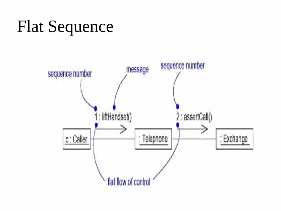
Flat Sequence

Creation ,Modification and destruction :
To specify if an object or link enters and/or leaves
during an interaction you can attach one of the
following constraints to the element:
New – link is created.
Destroyed – link is destroyed.
Transient – link is created during execution
of enclosing interaction.

Modeling a flow control
To model a flow of control
• Set the context for the interaction, whether it is the system as a whole, a class, or an individual operation.
• Set the stage for the interaction by identifying which objects play a role; set their initial properties, including their attribute values, state, and role.
• If your model emphasizes the structural organization of these objects, identify the links that connect them, relevant to the paths of communication that take place in this interaction. Specify the nature of the links using the UML's standard stereotypes and constraints, as necessary.

Modeling a flow control contd..
• In time order, specify the messages that pass from object to object. As necessary, distinguish the different kinds of messages; include parameters and return values to convey the necessary detail of this interaction.
• Also to convey the necessary detail of this interaction, adorn each object at every moment in time with its state and role.
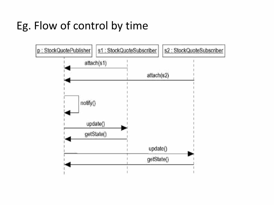
Eg. Flow of control by time
Eg. Flow of control by organization
INTERACTION DIAGRAMS
Interaction diagrams are not only important for
modeling the dynamic aspects of a system, but also
for constructing executable systems through forward
and reverse engineering.
• A sequence diagram is an interaction diagram that
emphasizes the time ordering of messages.
• A collaboration diagram is an interaction diagram
that emphasizes the structural organization of the
objects that send and receive messages.

INTERACTION DIAGRAMS contd…
Interaction diagrams commonly contain
• Objects
• Links
• Messages
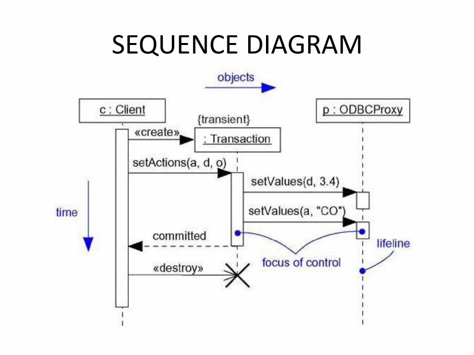
SEQUENCE DIAGRAM
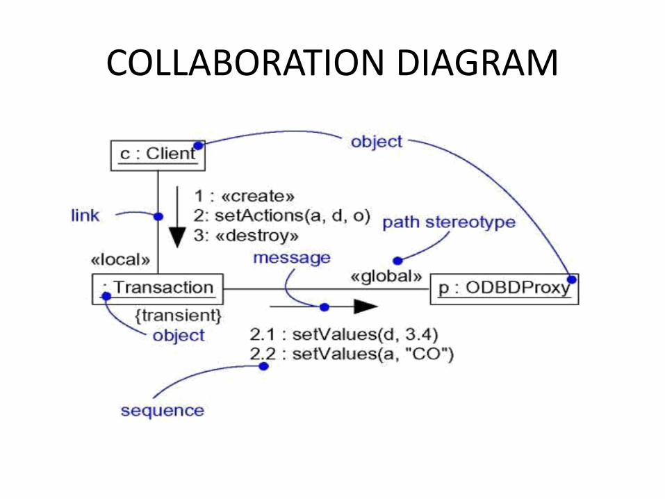
COLLABORATION DIAGRAM
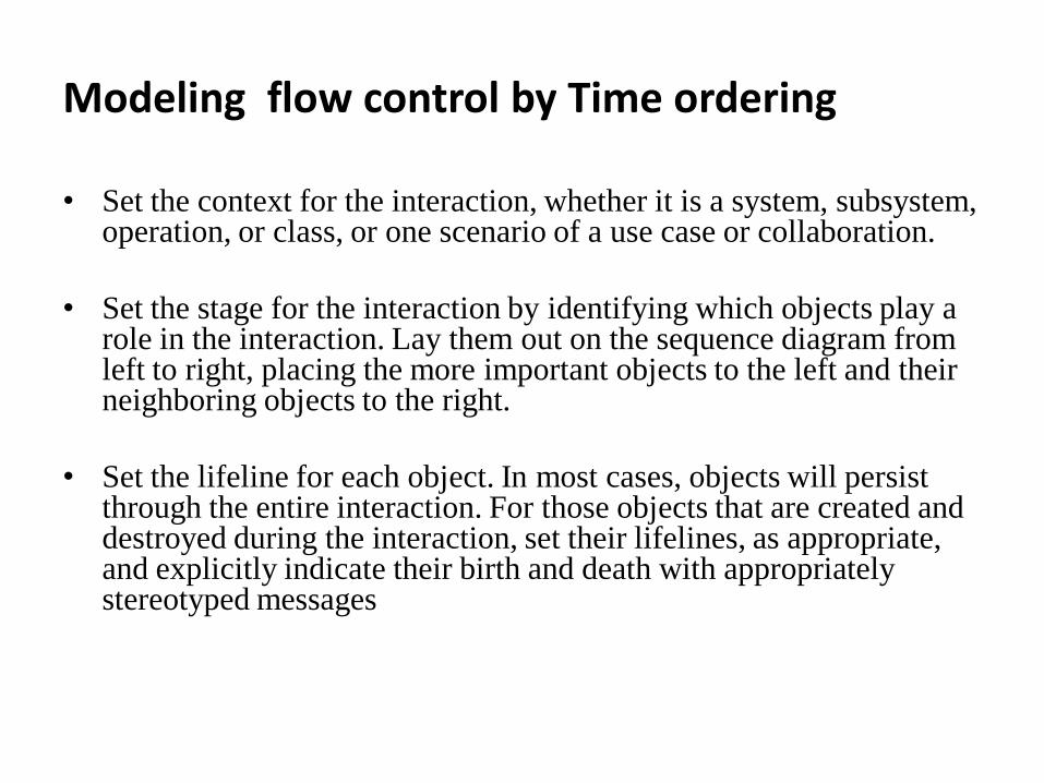
Modeling flow control by Time ordering
• Set the context for the interaction, whether it is a system, subsystem, operation, or class, or one scenario of a use case or collaboration.
• Set the stage for the interaction by identifying which objects play a role in the interaction. Lay them out on the sequence diagram from left to right, placing the more important objects to the left and their neighboring objects to the right.
• Set the lifeline for each object. In most cases, objects will persist through the entire interaction. For those objects that are created and destroyed during the interaction, set their lifelines, as appropriate, and explicitly indicate their birth and death with appropriately stereotyped messages

Modeling flow control by Time ordering contd..
• Starting with the message that initiates this interaction, lay out each subsequent message from top to bottom between the lifelines, showing each message's properties (such as its parameters), as necessary to explain the semantics of the interaction.
• If you need to visualize the nesting of messages or the points in time when actual computation is taking place, adorn each object's lifeline with its focus of control.
• If you need to specify time or space constraints, adorn each message with a timing mark and attach suitable time or space constraints.
• If you need to specify this flow of control more formally, attach pre- and postconditions to each message.
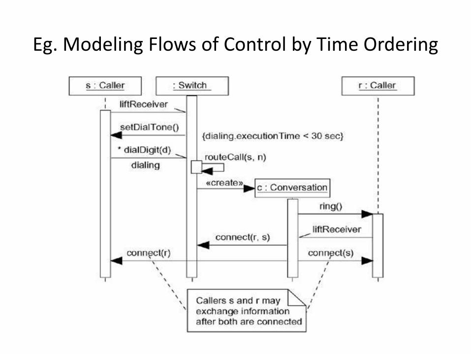
Eg. Modeling Flows of Control by Time Ordering
Modeling Flows of control by organization
• Set the context for the interaction, whether it is a system, subsystem,
operation, or class, or one scenario of a use case or collaboration.
• Set the stage for the interaction by identifying which objects play a role in the interaction. Lay them out on the collaboration diagram as vertices in a graph, placing the more important objects in the center of the diagram and their neighboring objects to the outside.
• Set the initial properties of each of these objects. If the attribute values, tagged values, state, or role of any object changes in significant ways over the duration of the interaction, place a duplicate object on the diagram, update it with these new values, and connect them by a message stereotyped as become or copy (with a suitable sequence number).
Modeling Flows of control by organization contd..
• Specify the links among these objects, along which messages may pass.
– Lay out the association links first; these are the most important ones,
because they represent structural connections.
– Lay out other links next, and adorn them with suitable path stereotypes
(such as global and local) to explicitly specify how these objects are related to one another.
• Starting with the message that initiates this interaction, attach each
subsequent message to the appropriate link, setting its sequence number, as appropriate. Show nesting by using Dewey decimal numbering.

Modeling Flows of control by organization contd..
• If you need to specify time or space constraints, adorn
each message with a timing mark and attach suitable
time or space constraints.
• If you need to specify this flow of control more
formally, attach pre- and post conditions to each
message.

Modeling Flows of control by organization
BASIC BEHAVIORAL MODELING -II
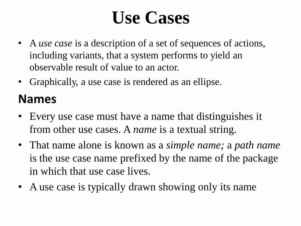
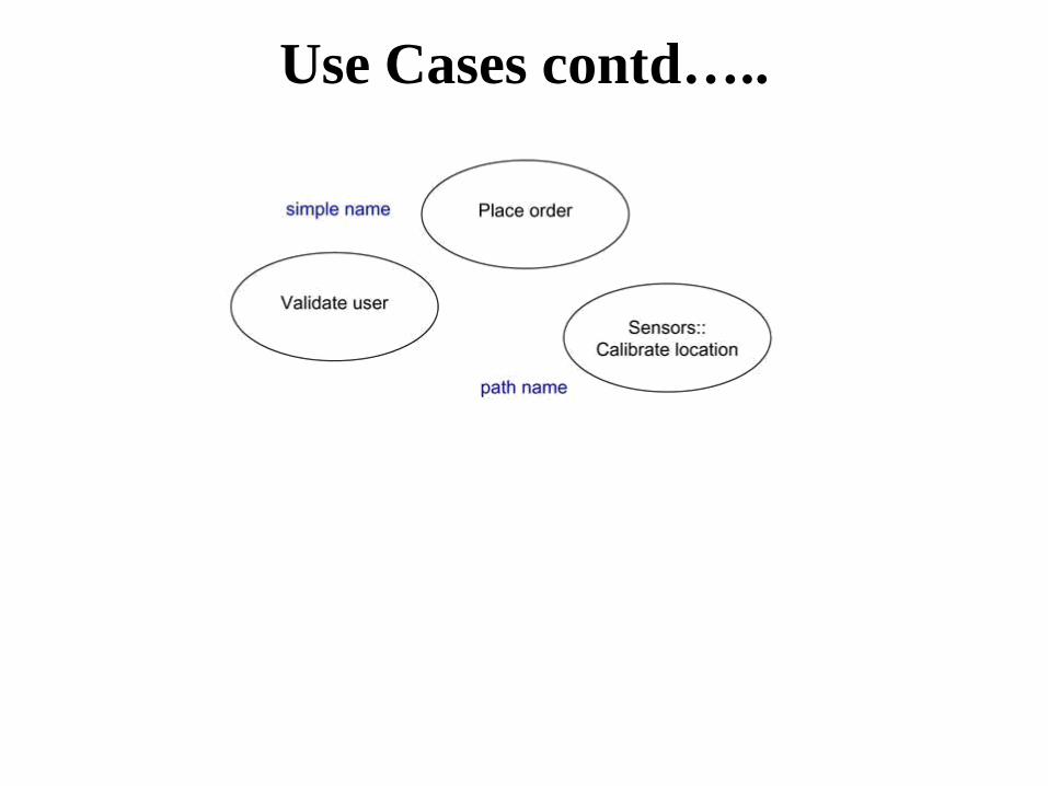
Use Cases
• A use case is a description of a set of sequences of actions,
including variants, that a system performs to yield an
observable result of value to an actor.
• Graphically, a use case is rendered as an ellipse.
Names • Every use case must have a name that distinguishes it
from other use cases. A name is a textual string.
• That name alone is known as a simple name; a path name
is the use case name prefixed by the name of the package
in which that use case lives.
• A use case is typically drawn showing only its name
Use Cases contd…..
Use Cases contd….. • Note
• A use case name may be text consisting of any number of
letters, numbers, and most punctuation marks (except for
marks such as the colon, which is used to separate a class
name and the name of its enclosing package) and may
continue over several lines
• Use Cases and Actors
• An actor represents a coherent set of roles that users of use
cases play when interacting with these use cases.
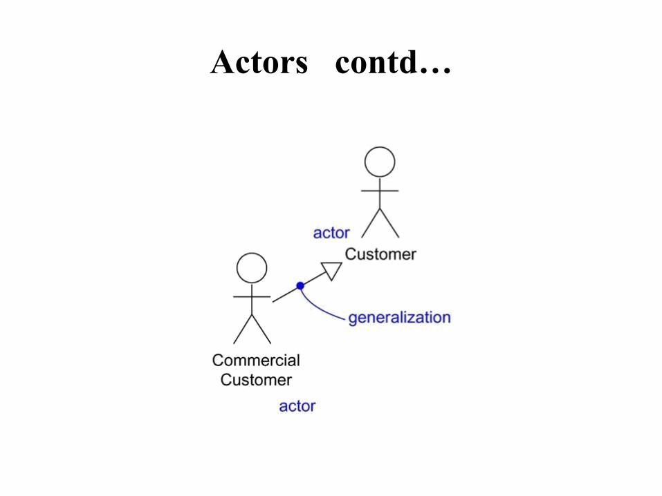
Actors contd…

Use Cases and Flow of Events
• A use case describes what a system (or a subsystem, class, or
interface) does but it does not specify how it does it. When you
model, it's important that you keep clear the separation of
concerns between this outside and inside view.
• Main flow of events:
• The use case starts when the system prompts the Customer for a
PIN number. The Customer can now enter a PIN number via the
keypad. The Customer commits the entry by pressing the Enter
button. The system then checks this PIN number to see if it is
valid. If the PIN number is valid, the system acknowledges the
entry, thus ending the use case.
• Exceptional flow of events:
• The Customer can cancel a transaction at any time by pressing
the Cancel button, thus restarting the use case. No changes are
made to the Customer's account.
•
• Exceptional flow of events:
• The Customer can clear a PIN number anytime before
committing it and reenter a new PIN number.
• Exceptional flow of events:
• If the Customer enters an invalid PIN number, the use
case restarts. If this happens three times in a row, the
system cancels the entire transaction, preventing the
Customer from interacting with the ATM for 60
seconds.
Use Cases and Scenarios
• Scenarios are to use cases as instances are to classes,
meaning that a scenario is basically one instance of a use
case.
• Use Cases and Collaborations
• A use case captures the intended behavior of the system
(or subsystem, class, or interface) you are developing,
without having to specify how that behavior is
implemented. That's an important separation because the
analysis of a system (which specifies behavior) should,
as much as possible, not be influenced by
implementation issues (which specify how that behavior
is to be carried out)
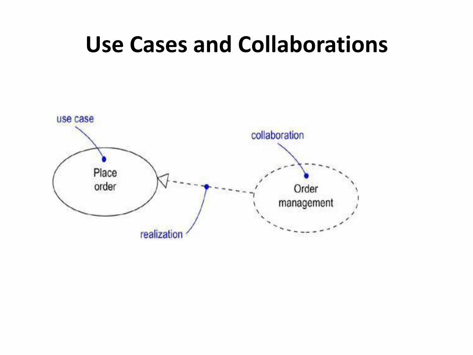
Use Cases and Collaborations

Organizing Use Cases • You can also organize use cases by specifying generalization,
include, and extend relationships among them. You apply
these relationships in order to factor common behavior (by
pulling such behavior from other use cases that it includes)
and in order to factor variants (by pushing such behavior into
other use cases that extend it).
• An include relationship between use cases means that the
base use case explicitly incorporates the behavior of another
use case at a location specified in the base.
• An extend relationship between use cases means that the base
use case implicitly incorporates the behavior of another use
case at a location specified indirectly by the extending use
case
Common Modeling Techniques
• Modeling the Behavior of an Element
To model the behavior of an element,
• Identify the actors that interact with the element. Candidate actors
include groups that require certain behavior to perform their tasks
or that are needed directly or indirectly to perform the element's
functions.
• Organize actors by identifying general and more specialized roles.
• For each actor, consider the primary ways in which that actor
interacts with the element. Consider also interactions that change
the state of the element or its environment or that involve a
response to some event.
• Consider also the exceptional ways in which each actor interacts
with the element.
• Organize these behaviors as use cases, applying include and extend
relationships to factor common behavior and distinguish
exceptional behavior

Modeling the Behavior of an Element
Use Case Diagrams
• A use case diagram is a diagram that shows a set of use
cases and actors and their relationships.
• Common Properties
A use case diagram is just a special kind of diagram and
shares the same common properties as do all other
diagrams• a name and graphical contents that are a
projection into a model. What distinguishes a use case
diagram from all other kinds of diagrams is its particular
content.
• Contents
• Use case diagrams commonly contain
• Use cases
• Actors
• Dependency, generalization, and association relationships

Common Modeling Techniques
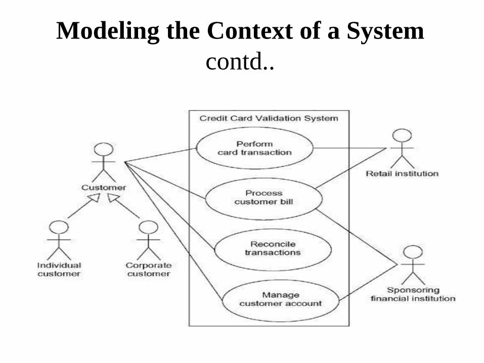
• Modeling the Context of a System
• To model the context of a system,
• Identify the actors that surround the system by considering
which groups require help from the system to perform their
tasks; which groups are needed to execute the system's
functions; which groups interact with external hardware or
other software systems; and which groups perform secondary
functions for administration and maintenance.
• Organize actors that are similar to one another in a
generalization/specialization hierarchy.
Modeling the Context of a System
contd.. • Where it aids understandability, provide a stereotype for
each such actor.
• Populate a use case diagram with these actors and specify
the paths of communication from each actor to the
system's use cases.
Modeling the Context of a System
contd..
Modeling the Requirements of a System
To model the requirements of a system,
• Establish the context of the system by identifying the actors
that surround it.
• For each actor, consider the behavior that each expects or
requires the system to provide.
• Name these common behaviors as use cases.
• Factor common behavior into new use cases that are used by
others; factor variant behavior into new use cases that extend
more main line flows.
• Model these use cases, actors, and their relationships in a use
case diagram.
• Adorn these use cases with notes that assert nonfunctional
requirements; you may have to attach some of these to the
whole system.
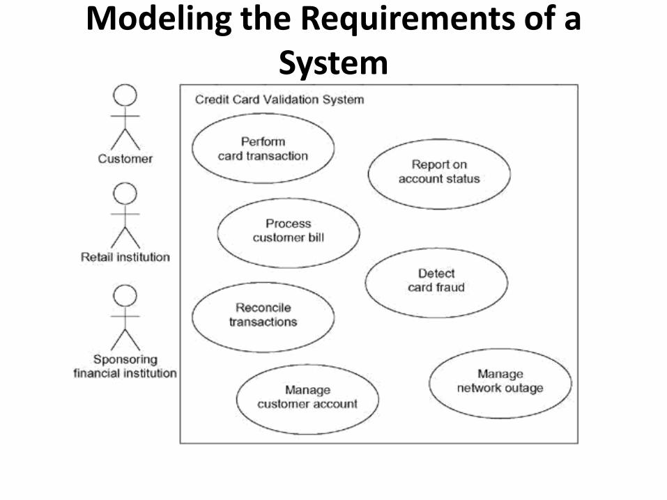
Modeling the Requirements of a System
Forward and Reverse Engineering • Forward engineering is the process of transforming a model into
code through a mapping to an implementation language
• To forward engineer a use case diagram,
• For each use case in the diagram, identify its flow of events and its exceptional flow of events.
• Depending on how deeply you choose to test, generate a test script for each flow, using the flow's preconditions as the test's initial state and its postconditions as its success criteria.
• As necessary, generate test scaffolding to represent each actor that interacts with the use case. Actors that push information to the element or are acted on by the element may either be simulated or substituted by its real-world equivalent.
• Use tools to run these tests each time you release the element to which the use case diagram applies.
• To reverse engineer a use case diagram,
• Identify each actor that interacts with the system.
• For each actor, consider the manner in which that actor interacts with the system, changes the state of the system or its environment, or responds to some event.
• Trace the flow of events in the executable system relative to each actor. Start with primary flows and only later consider alternative paths.
• Cluster related flows by declaring a corresponding use case. Consider modeling variants using extend relationships, and consider modeling common flows by applying include relationships.
• Render these actors and use cases in a use case diagram, and establish their relationships.
Activity Diagrams
• An activity diagram shows the flow from activity to activity. An is an ongoing nonatomic execution within a state machine.
• Contents
• Activity states and action states
• Transitions
• Objects
Action States and Activity States
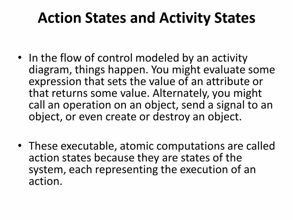
• In the flow of control modeled by an activity diagram, things happen. You might evaluate some expression that sets the value of an attribute or that returns some value. Alternately, you might call an operation on an object, send a signal to an object, or even create or destroy an object.
• These executable, atomic computations are called
action states because they are states of the system, each representing the execution of an action.
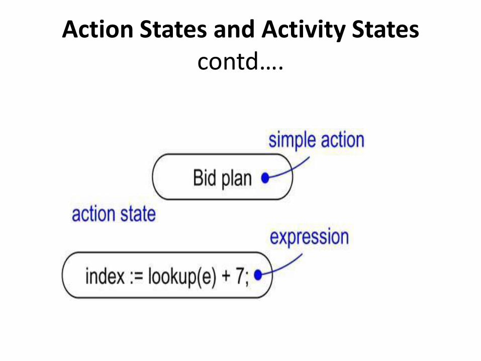
Action States and Activity States contd….
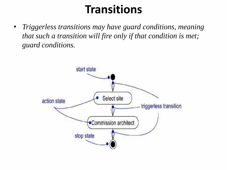
Transitions
• Triggerless transitions may have guard conditions, meaning
that such a transition will fire only if that condition is met;
guard conditions.
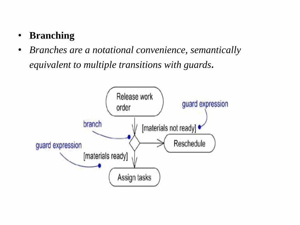
• Branching
• Branches are a notational convenience, semantically
equivalent to multiple transitions with guards.

Forking and Joining • As the figure also shows, a join represents the synchronization
of two or more concurrent flows of control. A join may have
two or more incoming transitions and one outgoing transition.
Above the join, the activities associated with each of these
paths continues in parallel. At the join, the concurrent flows
synchronize, meaning that each waits until all incoming flows
have reached the join, at which point one flow of control
continues on below the join.
• when you are modeling workflows of business processes• you
might encounter flows that are concurrent. In the UML, you
use a synchronization bar to specify the forking and joining of
these parallel flows of control. A synchronization bar is
rendered as a thick horizontal or vertical line.

Swimlanes • In the UML, each group is called a swimlane because,
visually, each group is divided from its neighbor by a vertical solid line.A swimlane specifies a locus of activities.
• Each swimlane has a name unique within its diagram. A swimlane really has no deep semantics, except that it may represent some real-world entity.
• Each swimlane represents a high-level responsibility for part of the overall activity of an activity diagram, and each swimlane may eventually be implemented by one or more classes. In an activity diagram partitioned into swimlanes, every activity belongs to exactly one swimlane, but transitions may cross lanes.
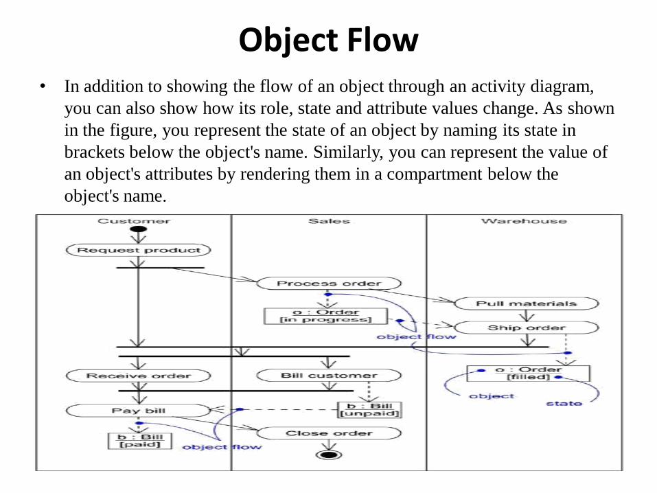
Object Flow • In addition to showing the flow of an object through an activity diagram,
you can also show how its role, state and attribute values change. As shown
in the figure, you represent the state of an object by naming its state in
brackets below the object's name. Similarly, you can represent the value of
an object's attributes by rendering them in a compartment below the
object's name.
Common Modeling Techniques • Modeling a Workflow
• To model a workflow,
• Establish a focus for the workflow. For nontrivial systems, it's
impossible to show all interesting workflows in one diagram.
• Select the business objects that have the high-level
responsibilities for parts of the overall workflow. These may
be real things from the vocabulary of the system, or they may
be more abstract. In either case, create a swimlane for each
important business object.
• Identify the preconditions of the workflow's initial state and
the postconditions of the workflow's final state. This is
important in helping you model the boundaries of the
workflow.
• Beginning at the workflow's initial state, specify the activities
and actions that take place over time and render them in the
activity diagram as either activity states or action states.
Modeling a Workflow contd..
• For complicated actions, or for sets of actions that appear multiple times, collapse these into activity states, and provide a separate activity diagram that expands on each.
• Render the transitions that connect these activity and action states. Start with the sequential flows in the workflow first, next consider branching, and only then consider forking and joining.
• If there are important objects that are involved in the workflow, render them in the activity diagram, as well. Show their changing values and state as necessary to communicate the intent of the object flow.

Modeling a Workflow contd..

Modeling an Operation
• To model an operation,
• Collect the abstractions that are involved in this operation. This includes the operation's parameters (including its return type, if any), the attributes of the enclosing class, and certain neighboring classes.
• Identify the preconditions at the operation's initial state and the postconditions at the operation's final state. Also identify any invariants of the enclosing class that must hold during the execution of the operation.
• Beginning at the operation's initial state, specify the activities and actions that take place over time and render them in the activity diagram as either activity states or action states.
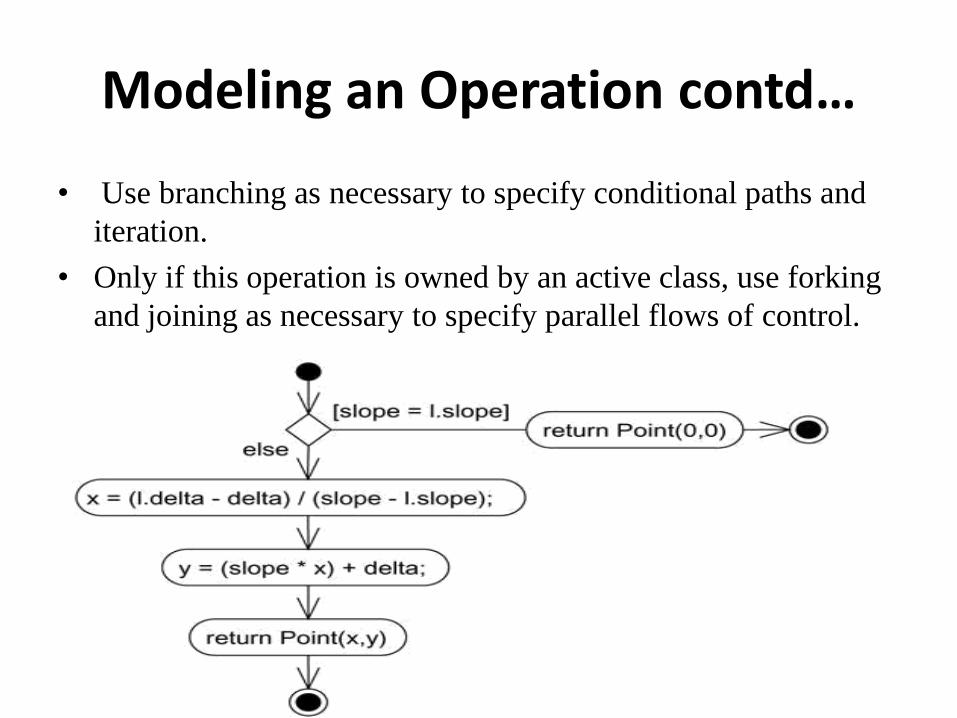
Modeling an Operation contd…
• Use branching as necessary to specify conditional paths and
iteration.
• Only if this operation is owned by an active class, use forking
and joining as necessary to specify parallel flows of control.

Forward and Reverse Engineering • Forward engineering (the creation of code from a model) is possible
for activity diagrams, especially if the context of the diagram is an operation. For example, using the previous activity diagram, a forward engineering tool could generate the following C++ code for the operation intersection.
•
Point Line::intersection (l : Line) { if (slope == l.slope) return Point(0,0); int x = (l.delta - delta) / (slope - l.slope); int y = (slope * x) + delta; return Point(x, y); }
Forward and Reverse Engineering contd…..
• Reverse engineering (the creation of a model from code) is
also possible for activity diagrams, especially if the context of
the code is the body of an operation. In particular, the previous
diagram could have been generated from the implementation
of the class Line.
UNIT-IV Advanced Behavioral Modeling
Architectural modeling

211
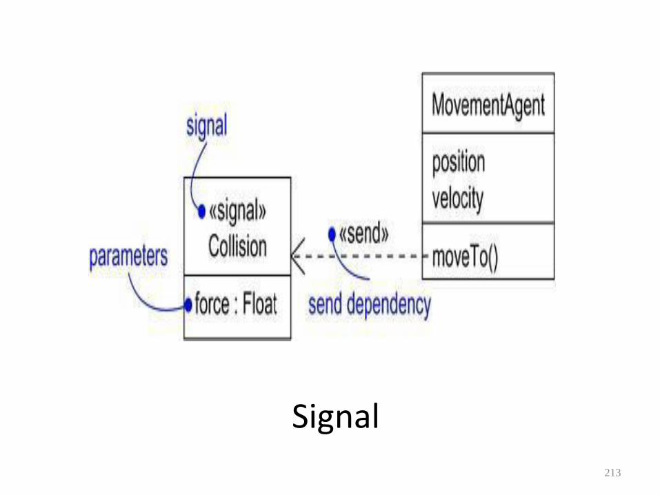
• Events and Signals
• An event is the specification of a significant occurrence that has a location in time and space. In the context of state machines, an event is an occurrence of a stimulus that can trigger a state transition.
• A signal is a kind of event that represents the specification of an asynchronous stimulus communicated between instances.

Event
212
Signal 213
Terms and Concepts
• Events may be external or internal. External events are those that pass between the system and its actors.
• Internal events are those that pass among the objects that live inside the system. An overflow exception is an example of an internal event.
214
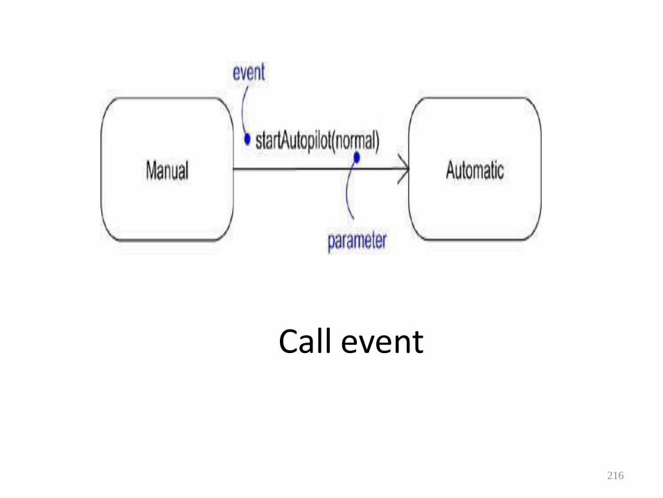
Call Events • Just as a signal event represents the
occurrence of a signal, a call event represents the dispatch of an operation.
• Whereas a signal is an asynchronous event, a call event is, in general, synchronous.
• This means that when an object invokes an operation on another object that has a state machine, control passes from the sender to the receiver, the transition is triggered by the event.
215
Call event
216
Time and Change Events
• A time event is an event that represents the passage of time. In the UML you model a time event by using the keyword after followed by some expression that evaluates to a period of time.
• A change event is an event that represents a change in state or the satisfaction of some condition. In the UML you model a change event by using the keyword when followed by some Boolean expression
217
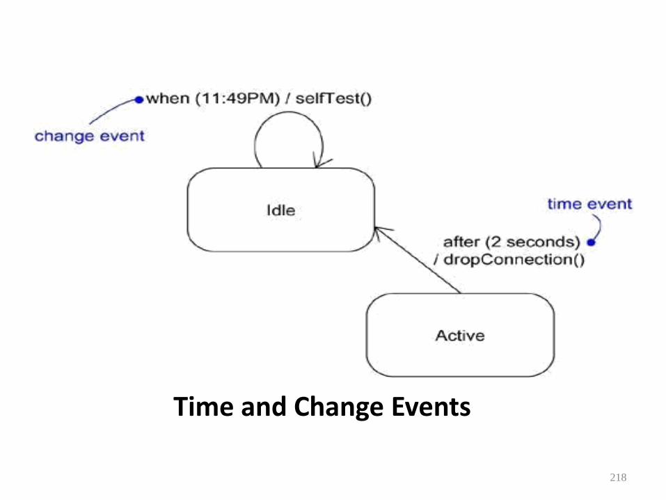
Time and Change Events
218

Sending and Receiving Events
• Signal events and call events involve at least two objects: the object that sends the signal or invokes the operation, and the object to which the event is directed.
• Because signals are asynchronous, and because asynchronous calls are themselves signals, the semantics of events interact with the semantics of active objects and passive objects.
219

Signals and Active Classes.
220

Common Modeling Techniques • Modeling a Family of Signals To model a family of signals, • Consider all the different kinds of signals to
which a given set of active objects may respond.
• Look for the common kinds of signals and place them in a generalization/specialization hierarchy using inheritance. Look for the opportunity for polymorphism in the state machines of these active objects.
221
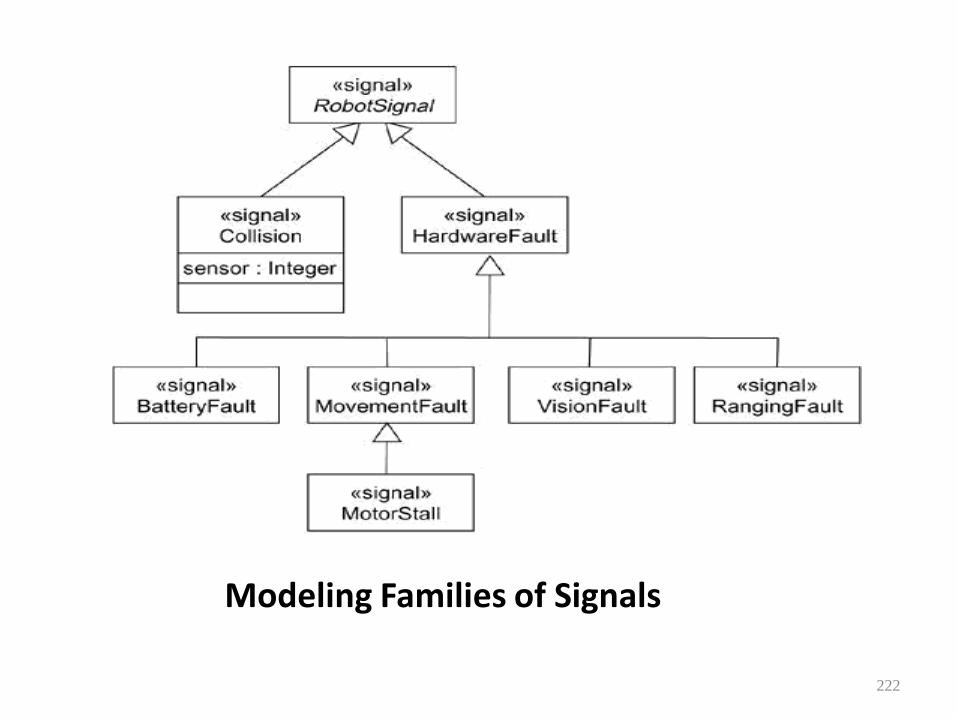
Modeling Families of Signals
222

Modeling Exceptions
• In the UML, exceptions are kinds of signals, which you model as stereotyped classes. Exceptions may be attached to specification operations.
• Modeling exceptions is somewhat the inverse of modeling a general family of signals.
223

• To model exceptions,
• For each class and interface, and for each operation of such elements, consider the exceptional conditions that may be raised.
• Arrange these exceptions in a hierarchy. Elevate
general ones, lower specialized ones, and introduce intermediate exceptions, as necessary.
• For each operation, specify the exceptions that it may
raise. You can do so explicitly (by showing send dependencies from an operation to its exceptions) or you can put this in the operation's specification.
224
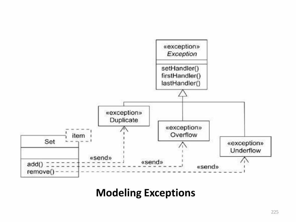
Modeling Exceptions
225

State Machines
• A state machine is a behavior that specifies the sequences of states an object goes through during its lifetime in response to events, together with its responses to those events.
• A state is a condition or situation during the life of an object during which it satisfies some condition, performs some activity, or waits for some event.
226

Terms and Concepts • A transition is a relationship between two states
indicating that an object in the first state will perform certain actions and enter the second state when a specified event occurs and specified conditions are satisfied.
• An activity is ongoing nonatomic execution within a state machine. An action is an executable atomic computation that results in a change in state of the model or the return of a value. Graphically, a state is rendered as a rectangle with rounded corners. A transition is rendered as a solid directed line
227

States
• A state is a condition or situation during the life of an object during which it satisfies some condition, performs some activity, or waits for some event. An object remains in a state for a finite amount of time.
228
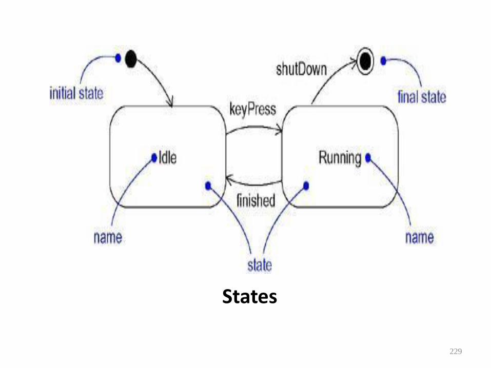
States
229
Transitions
• A transition is a relationship between two states indicating that an object in the first state will perform certain actions and enter the second state when a specified event occurs and specified conditions are satisfied.
230

Transitions
231

Common Modeling Techniques
• Modeling the Lifetime of an Object
• To model the lifetime of an object,
• Set the context for the state machine, whether it is a class, a use case, or the system as a whole.
• Establish the initial and final states for the object. To guide the rest of your model, possibly state the pre- and postconditions of the initial and final states, respectively.
232
• Decide on the events to which this object may respond.
• Starting from the initial state to the final state, lay out the top-level states the object may be in. Connect these states with transitions triggered by the appropriate events. Continue by adding actions to these transitions.
• Identify any entry or exit actions (especially if you find that the idiom they cover is used in the state machine).
233
• Expand these states as necessary by using substates.
• Check that all actions mentioned in the state machine are sustained by the relationships, methods, and operations of the enclosing object.
234
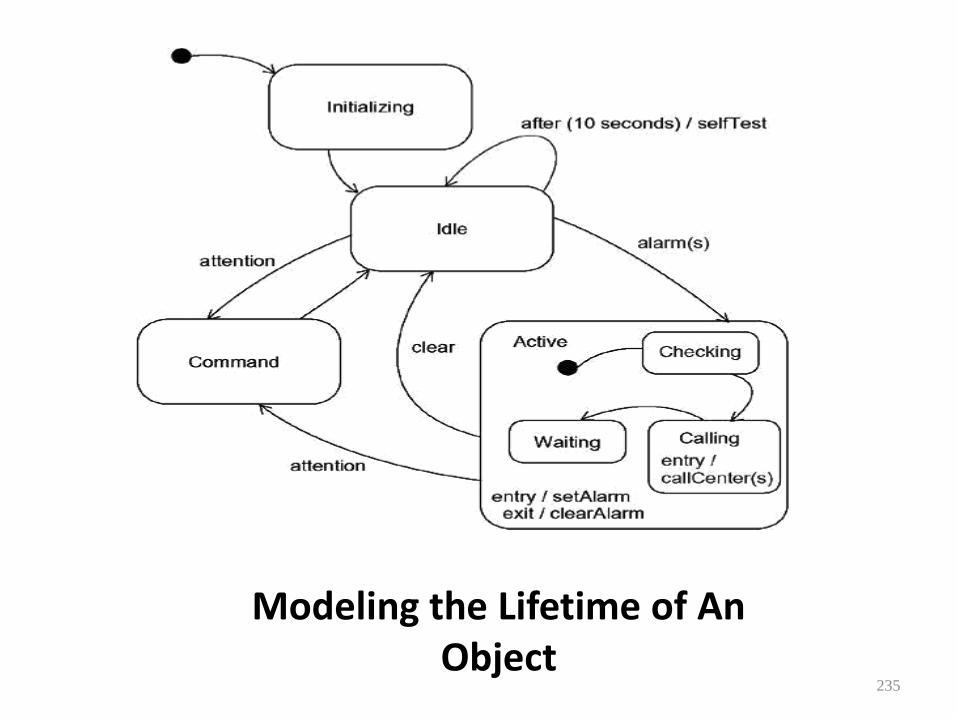
Modeling the Lifetime of An Object
235

Processes and Threads • Terms and Concepts
• A process is a heavyweight flow that can execute concurrently with other processes.
• A thread is a lightweight flow that can execute concurrently with other threads within the same process.
• Processes and threads are rendered as stereotyped active classes (and also appear as sequences in interaction diagrams).
236
Flow of Control • In a purely sequential system, there is one
flow of control.
• When a sequential program starts, control is rooted at the beginning of the program and operations are dispatched one after another.
• Even if there are concurrent things happening among the actors outside the system, a sequential program will process only one event at a time, queuing or discarding any concurrent external events.
237
Synchronization • Visualize for a moment the multiple flows of
control that weave through a concurrent system.
• When a flow passes through an operation, we say that at a given moment, the locus of control is in the operation.
• If that operation is defined for some class, we can also say that at a given moment, the locus of control is in a specific instance of that class.
238
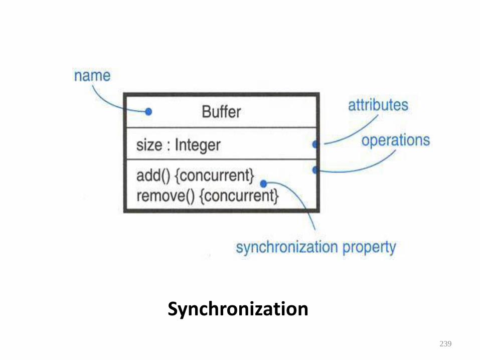
Synchronization
239

Common Modeling Techniques
• Modeling Multiple Flows of Control
• To model multiple flows of control,
• Identify the opportunities for concurrent action and reify each flow as an active class. Generalize common sets of active objects into an active class.
• Capture these static decisions in class diagrams, explicitly highlighting each active class.
240

Modeling Flows of Control
241
Modeling Interprocess Communication
• To model interprocess communication,
• Model the multiple flows of control.
• Consider which of these active objects represent processes and which represent threads.
• Model messaging using asynchronous communication.
• Informally specify the underlying mechanism for communication by using notes, or more formally by using collaborations.
242
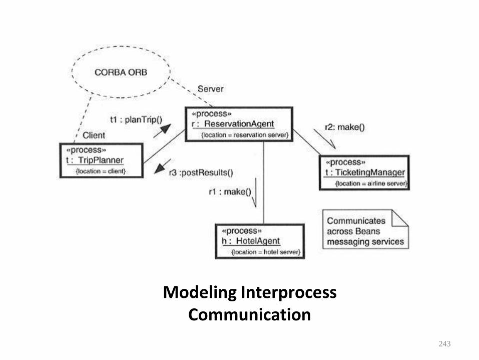
Modeling Interprocess
Communication
243
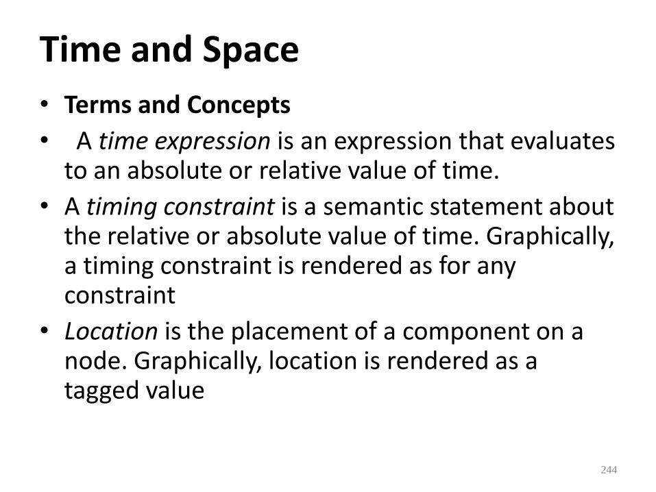
Time and Space
• Terms and Concepts
• A time expression is an expression that evaluates to an absolute or relative value of time.
• A timing constraint is a semantic statement about the relative or absolute value of time. Graphically, a timing constraint is rendered as for any constraint
• Location is the placement of a component on a node. Graphically, location is rendered as a tagged value
244

Time 245

Common Modeling Techniques
• Modeling Timing Constraints • To model timing constraints, • For each event in an interaction, consider whether it must
start at some absolute time. Model that real time property as a timing constraint on the message.
• • For each interesting sequence of messages in an
interaction, consider whether there is an associated maximum relative time for that sequence. Model that real time property as a timing constraint on the sequence.
• • For each time critical operation in each class, consider its
time complexity. Model those semantics as timing constraints on the operation
246

Modeling Timing Constraint
247
Modeling the Distribution of Objects •
• To model the distribution of objects, • For each interesting class of objects in your system, consider its locality of
reference. In other words, consider all its neighbors and their locations. A tightly coupled locality will have neighboring objects close by
• • Next consider patterns of interaction among related sets of objects. Co-
locate sets of objects that have high degrees of interaction, to reduce the cost of communication. Partition sets of objects that have low degrees of interaction.
• • Next consider the distribution of responsibilities across the system.
Redistribute your objects to balance the load of each node. • • Consider also issues of security, volatility, and quality of service, and
redistribute your objects as appropriate.
248
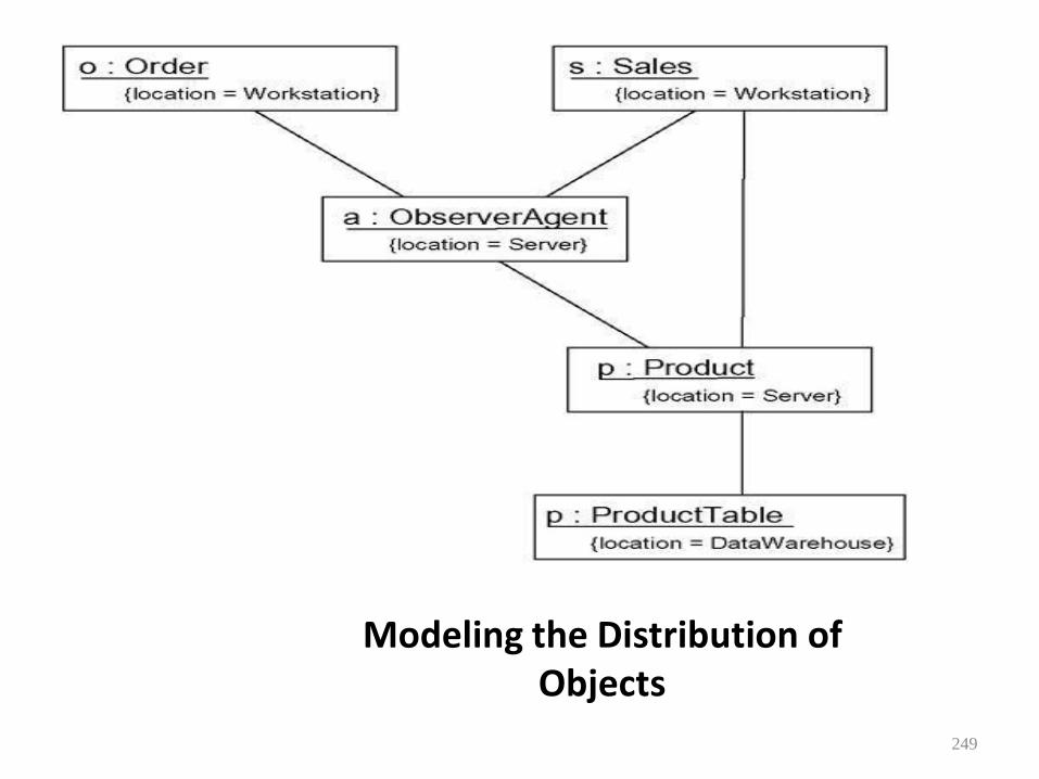
Modeling the Distribution of Objects
249
Modeling Objects that Migrate
To model the migration of objects,
• Select an underlying mechanism for physically transporting objects across nodes.
• Render the allocation of an object to a node by
explicitly indicating its location as a tagged value. • Using the become and copy stereotyped messages,
render the allocation of an object to a new node. • Consider the issues of synchronization (keeping the
state of cloned objects consistent) and identity (preserving the name of the object as it moves).
250
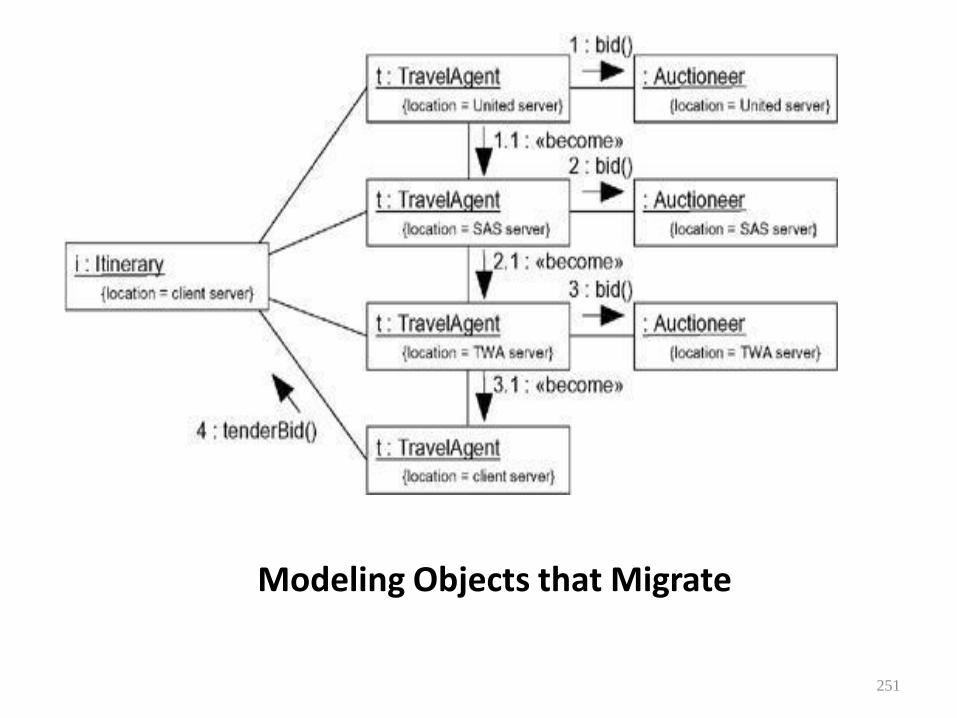
Modeling Objects that Migrate
251
Statechart Diagrams • Terms and Concepts • A statechart diagram shows a state machine,
emphasizing the flow of control from state to state.
• A state machine is a behavior that specifies the sequences of states an object goes through during its lifetime in response to events, together with its responses to those events. A
• state is a condition or situation in the life of an object during which it satisfies some condition, performs some activity, or waits for some event.
252
Contents • Statechart diagrams commonly contain
• Simple states and composite states
• Transitions, including events and actions
A statechart diagram is basically a projection of the elements found in a state machine. This means that statechart diagrams may contain branches, forks, joins, action states, activity states, objects, initial states, final states, history states,
253

Common Modeling Technique • Modeling Reactive Objects
• To model a reactive object, • Choose the context for the state machine, whether it is a
class, a use case, or the system as a whole. • • Choose the initial and final states for the object. To guide
the rest of your model, possibly state the pre- and postconditions of the initial and final states, respectively.
• • Decide on the stable states of the object by considering the
conditions in which the object may exist for some identifiable period of time. Start with the high-level states of the object and only then consider its possible substates.
254
• Decide on the meaningful partial ordering of stable states over the lifetime of the object.
• • Decide on the events that may trigger a transition from
state to state. Model these events as triggers to transitions that move from one legal ordering of states to another.
• • Attach actions to these transitions (as in a Mealy machine)
and/or to these states (as in a Moore machine). • • Consider ways to simplify your machine by using substates,
branches, forks, joins, and history states.
255
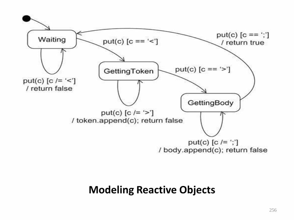
Modeling Reactive Objects
256
Forward and Reverse Engineering • Forward engineering(the creation of code
from a model) is possible for statechart diagrams, especially if the context of the diagram is a class.
257
• The forward engineering tool must generate the necessary private attributes and final static constants.
• • Reverse engineering (the creation of a model from code) is theoretically
possible, but practically not very useful. The choice of what constitutes a meaningful state is in the eye of the designer.
• Reverse engineering tools have no capacity for abstraction and therefore cannot automatically produce meaningful statechart diagrams.
• More interesting than the reverse engineering of a model from code is the animation of a model against the execution of a deployed system. For example, given the previous diagram, a tool could animate the states in the diagram as they were reached in the running system. Similarly, the firing of transitions could be animated, showing the receipt of events and the resulting dispatch of actions
258
ARCHITECTURAL MODELING
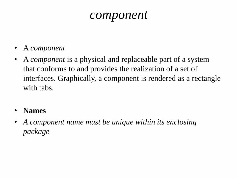
component
• A component
• A component is a physical and replaceable part of a system
that conforms to and provides the realization of a set of
interfaces. Graphically, a component is rendered as a rectangle
with tabs.
• Names
• A component name must be unique within its enclosing
package

component

Components and Classes
• there are some significant differences between components and classes.
• Classes represent logical abstractions; components represent physical things that live in the world of bits. In short, components may live on nodes, classes may not.
• Components represent the physical packaging of otherwise logical components and are at a different level of abstraction.
• Classes may have attributes and operations directly. In general, components only have operations that are reachable only through their interfaces.


Components and Interfaces • An interface is a collection of operations that are used to specify a
service of a class or a component. The relationship between component and interface is important. All the most common component-based operating system facilities (such as COM+, CORBA, and Enterprise Java Beans) use interfaces as the glue that binds components together.
• An interface that a component realizes is called an export interface, meaning an interface that the component provides as a service to other components. A component may provide many export interfaces. The interface that a component uses is called an import interface, meaning an interface that the component conforms to and so builds on. A component may conform to many import interfaces. Also, a component may both import and export interfaces.
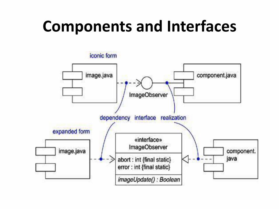
Components and Interfaces

Binary Replaceability • The basic intent of every component-based operating system
facility is to permit the assembly of systems from binary replaceable parts.
• This means that you can create a system out of components and then evolve that system by adding new components and replacing old ones, without rebuilding the system.
• Interfaces are the key to making this happen. When you specify an interface, you can drop into the executable system any component that conforms to or provides that interface.
• You can extend the system by making the components provide new services through other interfaces, which, in turn, other components can discover and use. These semantics explain the intent behind the definition of components in the UML.
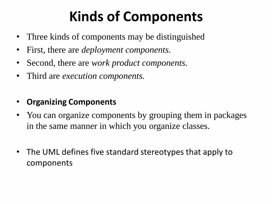
Kinds of Components • Three kinds of components may be distinguished
• First, there are deployment components.
• Second, there are work product components.
• Third are execution components.
• Organizing Components
• You can organize components by grouping them in packages
in the same manner in which you organize classes.
• The UML defines five standard stereotypes that apply to components

The UML defines five standard stereotypes that apply to
components
1.Executable
2. library
3. table
4. file
5. Document

Common Modeling Techniques • Modeling Executables and Libraries
• To model executables and libraries,
• Identify the partitioning of your physical system.
Consider the impact of technical, configuration
management, and reuse issues.
• Model any executables and libraries as components, using
the appropriate standard elements. If your implementation
introduces new kinds of components, introduce a new
appropriate stereotype.
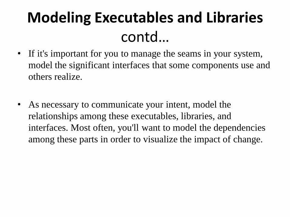
Modeling Executables and Libraries contd…
• If it's important for you to manage the seams in your system,
model the significant interfaces that some components use and
others realize.
• As necessary to communicate your intent, model the
relationships among these executables, libraries, and
interfaces. Most often, you'll want to model the dependencies
among these parts in order to visualize the impact of change.
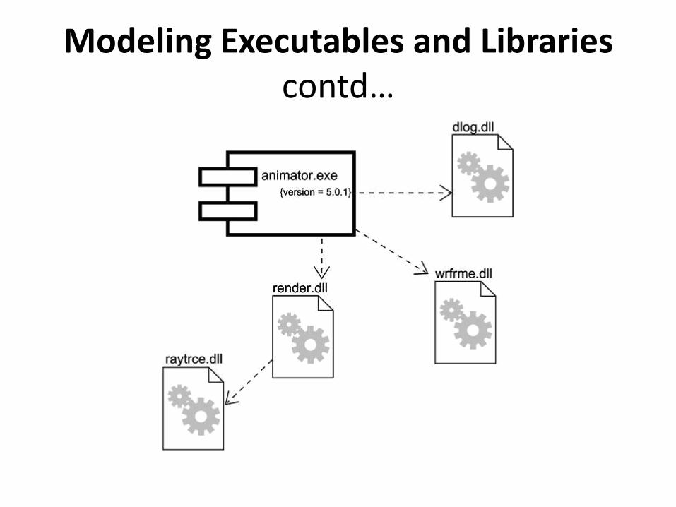
Modeling Executables and Libraries contd…
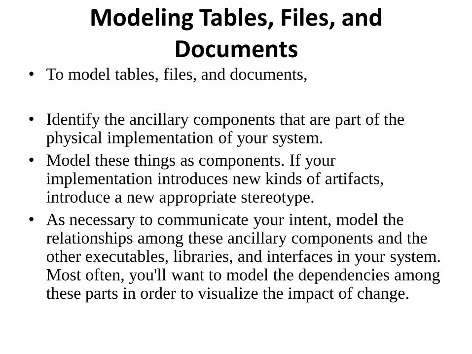
Modeling Tables, Files, and Documents
• To model tables, files, and documents,
• Identify the ancillary components that are part of the physical implementation of your system.
• Model these things as components. If your implementation introduces new kinds of artifacts, introduce a new appropriate stereotype.
• As necessary to communicate your intent, model the relationships among these ancillary components and the other executables, libraries, and interfaces in your system. Most often, you'll want to model the dependencies among these parts in order to visualize the impact of change.
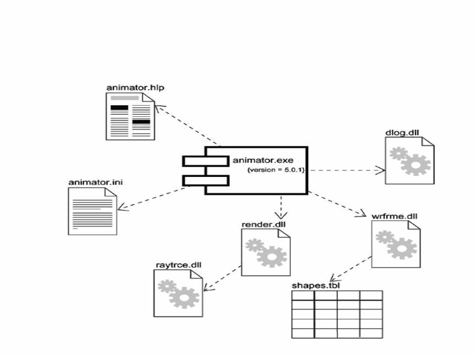

Modeling an API • To model an API,
• Identify the programmatic seams in your system and
model each seam as an interface, collecting the attributes
and operations that form this edge.
• Expose only those properties of the interface that are
important to visualize in the given context; otherwise,
hide these properties, keeping them in the interface's
specification for reference, as necessary.
• Model the realization of each API only insofar as it is
important to show the configuration of a specific
implementation.
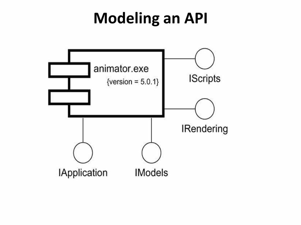
Modeling an API
Modeling Source Code • To model source code,
• Depending on the constraints imposed by your development tools, model the files used to store the details of all your logical elements, along with their compilation dependencies.
• If it's important for you to bolt these models to your configuration management and version control tools, you'll want to include tagged values, such as version, author, and check in/check out information, for each file that's under configuration management.
• As far as possible, let your development tools manage the relationships among these files, and use the UML only to visualize and document these relationships.

Modeling Source Code
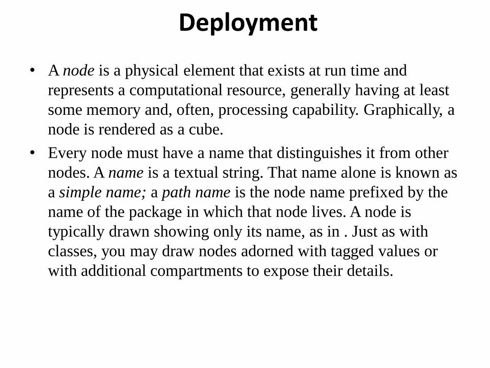
Deployment
• A node is a physical element that exists at run time and
represents a computational resource, generally having at least
some memory and, often, processing capability. Graphically, a
node is rendered as a cube.
• Every node must have a name that distinguishes it from other
nodes. A name is a textual string. That name alone is known as
a simple name; a path name is the node name prefixed by the
name of the package in which that node lives. A node is
typically drawn showing only its name, as in . Just as with
classes, you may draw nodes adorned with tagged values or
with additional compartments to expose their details.
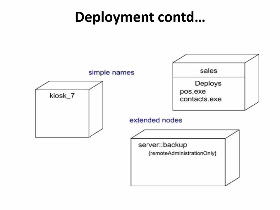
Deployment contd…
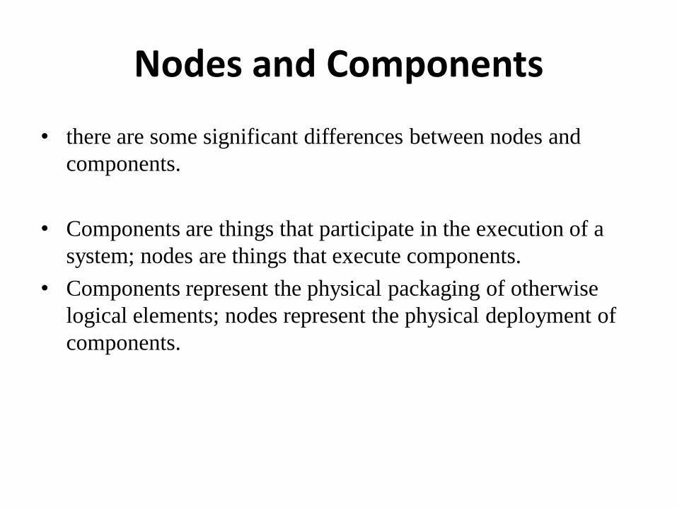
Nodes and Components
• there are some significant differences between nodes and
components.
• Components are things that participate in the execution of a
system; nodes are things that execute components.
• Components represent the physical packaging of otherwise
logical elements; nodes represent the physical deployment of
components.
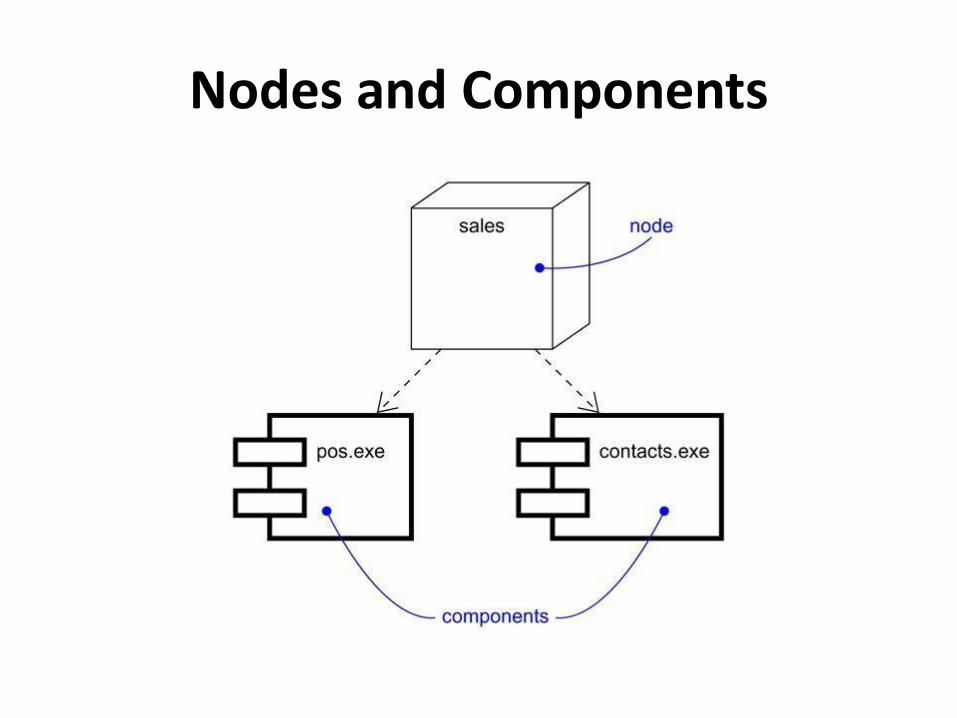
Nodes and Components
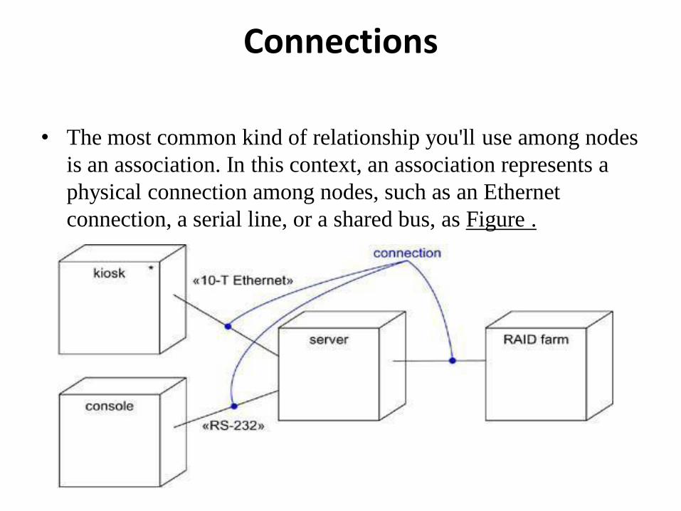
Connections
• The most common kind of relationship you'll use among nodes
is an association. In this context, an association represents a
physical connection among nodes, such as an Ethernet
connection, a serial line, or a shared bus, as Figure .
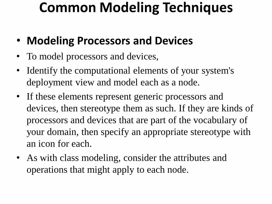
Common Modeling Techniques • Modeling Processors and Devices
• To model processors and devices,
• Identify the computational elements of your system's
deployment view and model each as a node.
• If these elements represent generic processors and
devices, then stereotype them as such. If they are kinds of
processors and devices that are part of the vocabulary of
your domain, then specify an appropriate stereotype with
an icon for each.
• As with class modeling, consider the attributes and
operations that might apply to each node.

Modeling Processors and Devices contd….

Modeling the Distribution of Components
• To model the distribution of components,
• For each significant component in your system, allocate it to a
given node.
• Consider duplicate locations for components. It's not
uncommon for the same kind of component (such as specific
executables and libraries) to reside on multiple nodes
simultaneously.
• Render this allocation in one of three ways.
• Don't make the allocation visible, but leave it as part of the
backplane of your model• that is, in each node's specification.
• Using dependency relationships, connect each node with the
components it deploys.
• List the components deployed on a node in an additional
compartment.
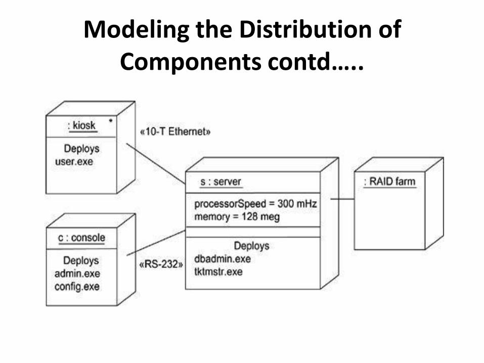
Modeling the Distribution of Components contd…..
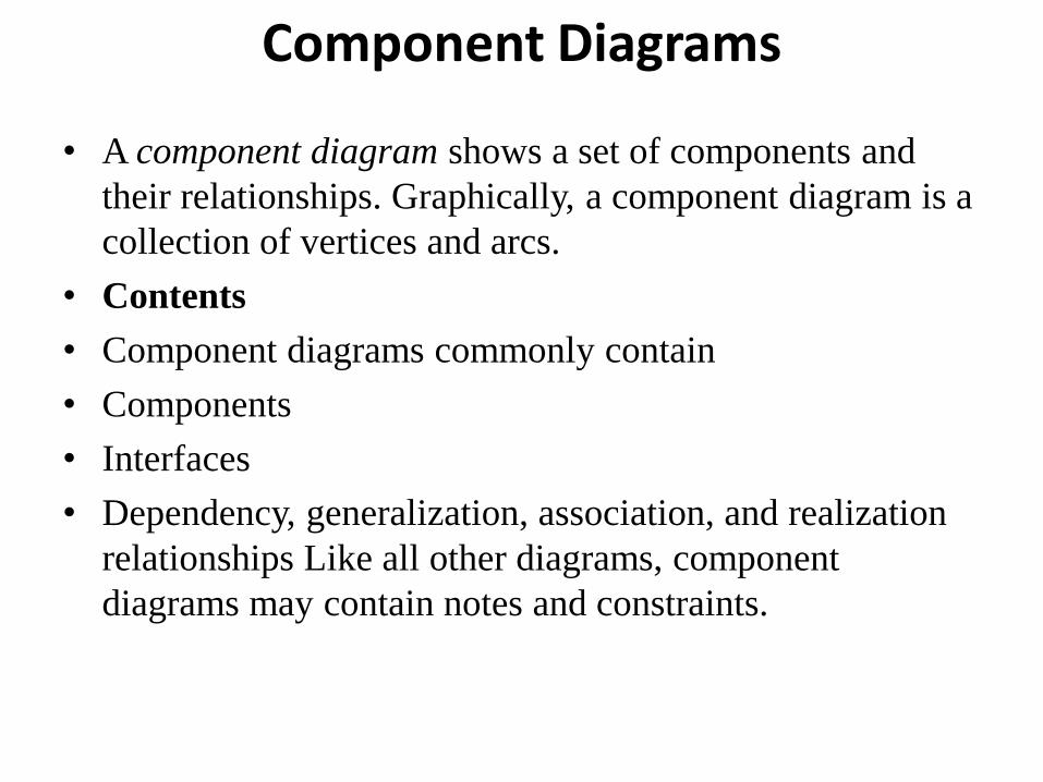
Component Diagrams
• A component diagram shows a set of components and
their relationships. Graphically, a component diagram is a
collection of vertices and arcs.
• Contents
• Component diagrams commonly contain
• Components
• Interfaces
• Dependency, generalization, association, and realization
relationships Like all other diagrams, component
diagrams may contain notes and constraints.

Common uses
• When you model the static implementation view of a system,
you'll typically use component diagrams in one of four ways.
• To model source code
• 2 model executable releases
• To model physical databases
• To model adaptable systems
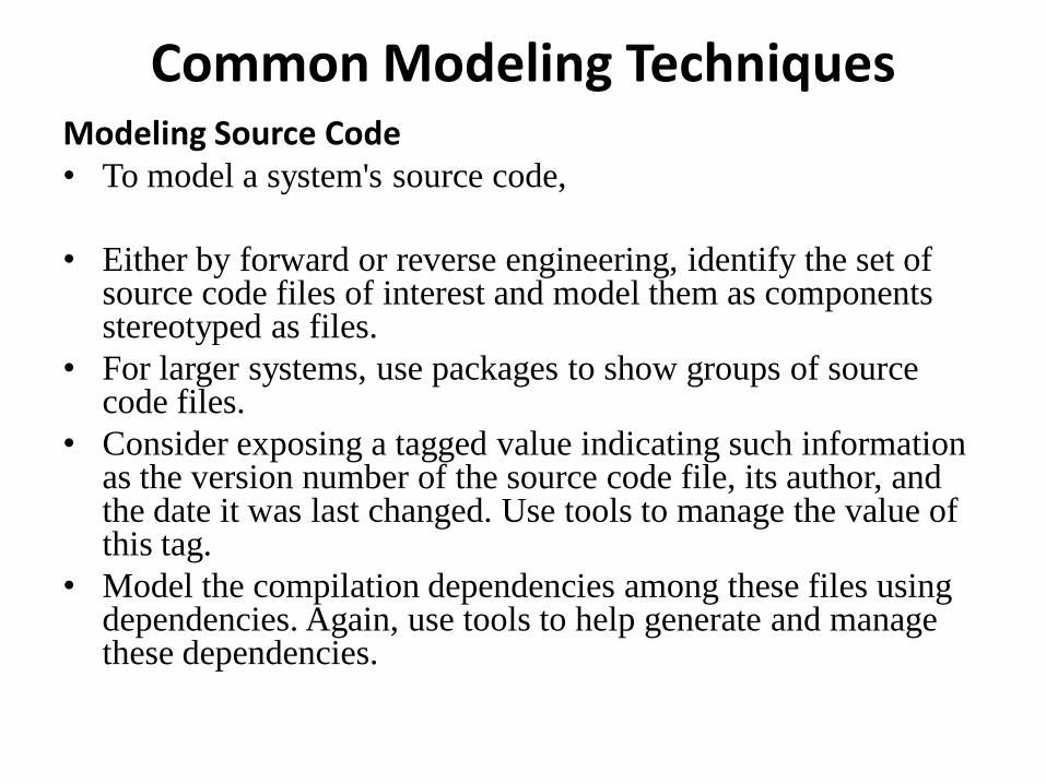
Common Modeling Techniques Modeling Source Code
• To model a system's source code,
• Either by forward or reverse engineering, identify the set of source code files of interest and model them as components stereotyped as files.
• For larger systems, use packages to show groups of source code files.
• Consider exposing a tagged value indicating such information as the version number of the source code file, its author, and the date it was last changed. Use tools to manage the value of this tag.
• Model the compilation dependencies among these files using dependencies. Again, use tools to help generate and manage these dependencies.
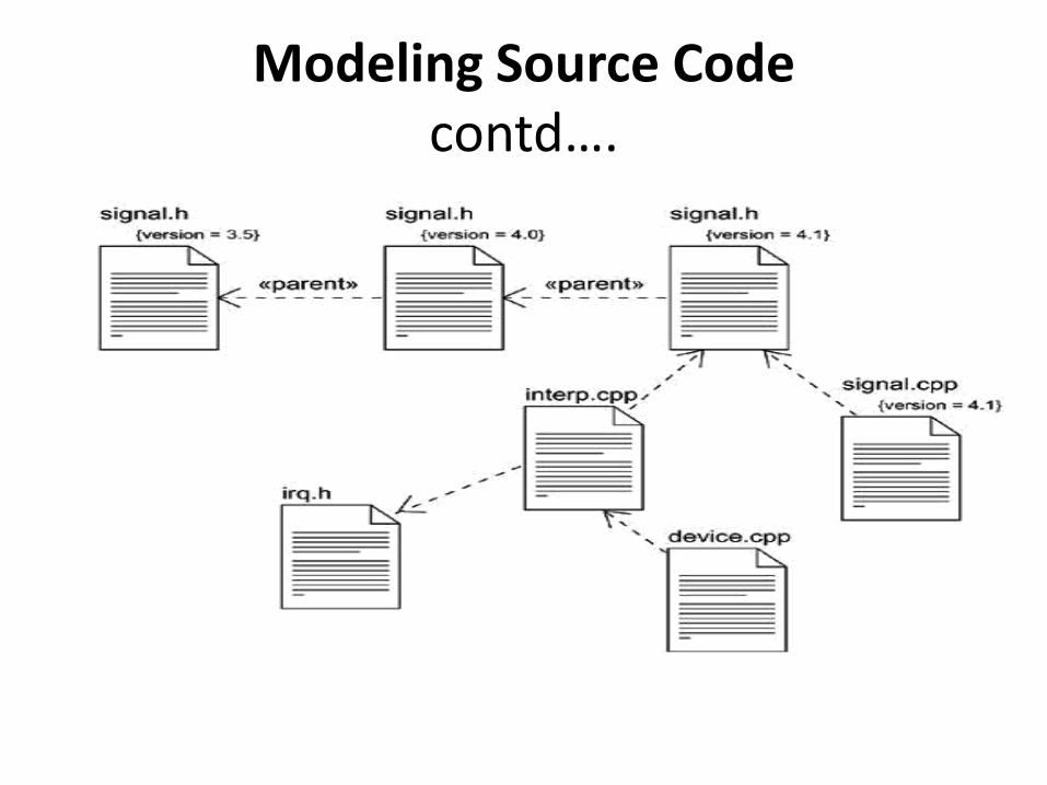
Modeling Source Code contd….
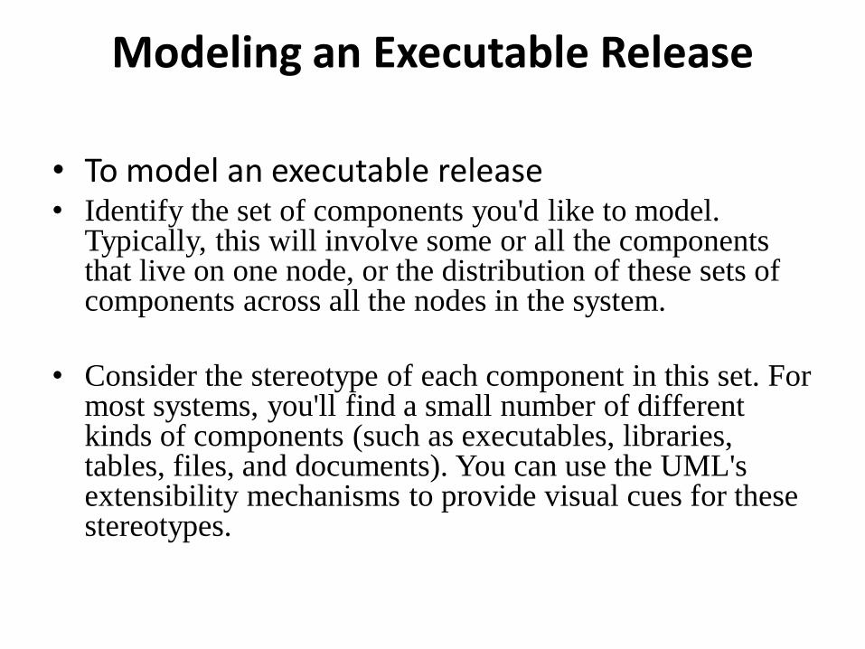
Modeling an Executable Release
• To model an executable release • Identify the set of components you'd like to model.
Typically, this will involve some or all the components that live on one node, or the distribution of these sets of components across all the nodes in the system.
• Consider the stereotype of each component in this set. For most systems, you'll find a small number of different kinds of components (such as executables, libraries, tables, files, and documents). You can use the UML's extensibility mechanisms to provide visual cues for these stereotypes.

Modeling an Executable Release contd….
• For each component in this set, consider its relationship to
its neighbors. Most often, this will involve interfaces that
are exported (realized) by certain components and then
imported (used) by others. If you want to expose the
seams in your system, model these interfaces explicitly. If
you want your model at a higher level of abstraction,
elide these relationships by showing only dependencies
among the components.

Modeling a Physical Database
• to model a physical database,
• Identify the classes in your model that represent your logical database schema.
• Select a strategy for mapping these classes to tables. You will also want to consider the physical distribution of your databases. Your mapping strategy will be affected by the location in which you want your data to live on your deployed system.
• To visualize, specify, construct, and document your mapping, create a component diagram that contains components stereotyped as tables.
• Where possible, use tools to help you transform your logical design into a physical design.

Modeling a Physical Database contd…
Modeling Adaptable Systems
• Consider the physical distribution of the components that may migrate from node to node. You can specify the location of a component instance by marking it with a location tagged value, which you can then render in a component diagram (although, technically speaking, a diagram that contains only instances is an object diagram).
• If you want to model the actions that cause a component to migrate, create a corresponding interaction diagram that contains component instances. You can illustrate a change of location by drawing the same instance more than once, but with different values for its location tagged value.
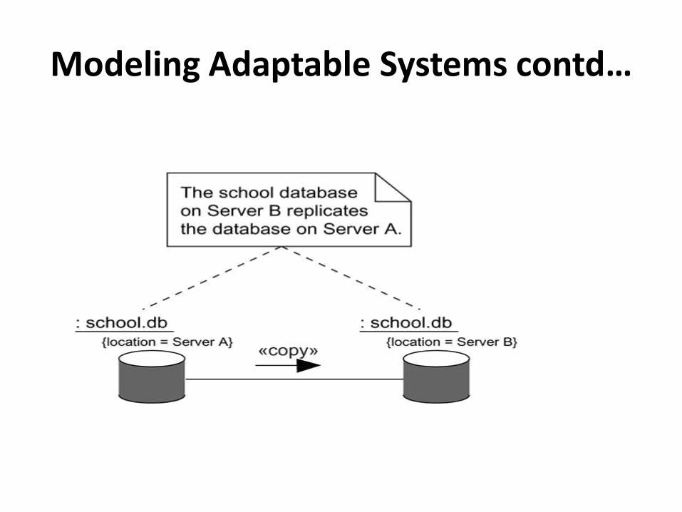
Modeling Adaptable Systems contd…
Forward and Reverse Engineering • To forward engineer a component diagram,
• For each component, identify the classes or collaborations that
the component implements.
• Choose the target for each component. Your choice is basically
between source code (a form that can be manipulated by
development tools) or a binary library or executable (a form
that can be dropped into a running system).
• Use tools to forward engineer your models.
•
Forward and Reverse Engineering • To reverse engineer a component diagram,
• Choose the target you want to reverse engineer. Source code can be reverse engineered to components and then classes. Binary libraries can be reverse engineered to uncover their interfaces. Executables can be reverse engineered the least.
• Using a tool, point to the code you'd like to reverse engineer. Use your tool to generate a new model or to modify an existing one that was previously forward engineered.
• Using your tool, create a component diagram by querying the model. For example, you might start with one or more components, then expand the diagram by following relationships or neighboring components. Expose or hide the details of the contents of this component diagram as necessary to communicate your intent.
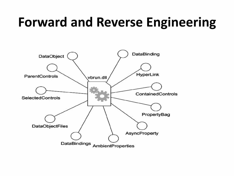
Forward and Reverse Engineering

Deployment Diagrams
• A deployment is a diagram that shows the configuration of
run time processing nodes and the components that live on
them. Graphically, a deployment diagram is a collection of
vertices and arcs.
• Contents • Deployment diagrams commonly contain
• Nodes
• Dependency and association relationships
• Like all other diagrams, deployment diagrams may contain
notes and constraints
Common Uses
• When you model the static deployment view of a system,
you'll typically use deployment diagrams in one of three ways.
• 1. To model embedded systems
• 2. To model client/server systems
• 3. To model fully distributed systems

Common Modeling Techniques
• Modeling an Embedded System
• To model an embedded system,
• Identify the devices and nodes that are unique to your system.
• Provide visual cues, especially for unusual devices, by using the UML's extensibility mechanisms to define system-specific stereotypes with appropriate icons. At the very least, you'll want to distinguish processors (which contain software components) and devices (which, at that level of abstraction, don't directly contain software).
Modeling an Embedded System contd….
• Model the relationships among these processors and devices in
a deployment diagram. Similarly, specify the relationship
between the components in your system's implementation
view and the nodes in your system's deployment view.
• As necessary, expand on any intelligent devices by modeling
their structure with a more detailed deployment diagram.
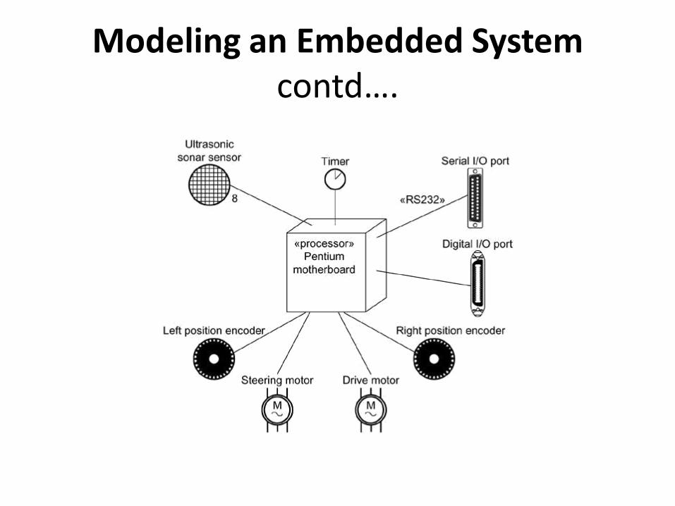
Modeling an Embedded System contd….

Modeling a Client/Server System
• To model a client/server system,
• Identify the nodes that represent your system's client and server processors.
• Highlight those devices that are germane to the behavior of your system. For example, you'll want to model special devices, such as credit card readers, badge readers, and display devices other than monitors, because their placement in the system's hardware topology are likely to be architecturally significant.
• Provide visual cues for these processors and devices via stereotyping.
• Model the topology of these nodes in a deployment diagram. Similarly, specify the relationship between the components in your system's implementation view and the nodes in your system's deployment view.

Modeling a Client/Server System

Modeling a Fully Distributed System
• To model a fully distributed system,
• Identify the system's devices and processors as for
simpler client/server systems.
• If you need to reason about the performance of the
system's network or the impact of changes to the network,
be sure to model these communication devices to the
level of detail sufficient to make these assessments.
• Pay close attention to logical groupings of nodes, which
you can specify by using packages.

Modeling a Fully Distributed System
• Model these devices and processors using deployment
diagrams. Where possible, use tools that discover the
topology of your system by walking your system's
network.
•
• If you need to focus on the dynamics of your system,
introduce use case diagrams to specify the kinds of
behavior you are interested in, and expand on these use
cases with interaction diagrams.
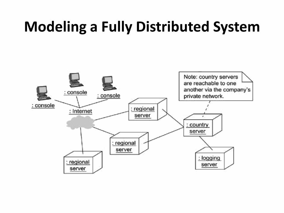
Modeling a Fully Distributed System

Forward and Reverse Engineering
• To reverse engineer a deployment diagram,
• Choose the target that you want to reverse engineer. In some cases, you'll want to sweep across your entire network; in others, you can limit your search.
• Choose also the fidelity of your reverse engineering. In some cases, it's sufficient to reverse engineer just to the level of all the system's processors; in others, you'll want to reverse engineer the system's networking peripherals, as well.
• Use a tool that walks across your system, discovering its hardware topology. Record that topology in a deployment model.
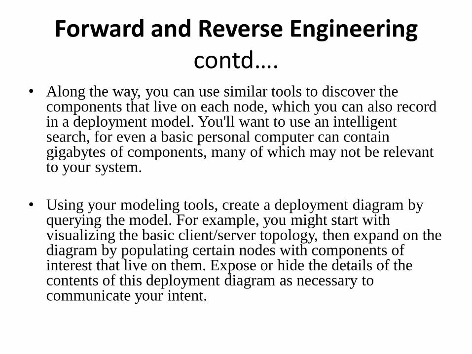
Forward and Reverse Engineering contd….
• Along the way, you can use similar tools to discover the components that live on each node, which you can also record in a deployment model. You'll want to use an intelligent search, for even a basic personal computer can contain gigabytes of components, many of which may not be relevant to your system.
• Using your modeling tools, create a deployment diagram by querying the model. For example, you might start with visualizing the basic client/server topology, then expand on the diagram by populating certain nodes with components of interest that live on them. Expose or hide the details of the contents of this deployment diagram as necessary to communicate your intent.
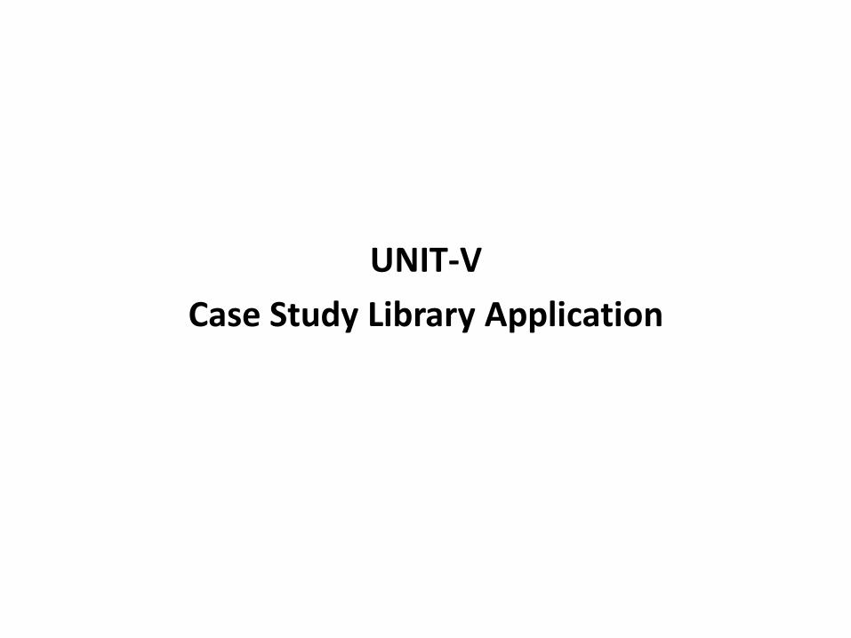
UNIT-V
Case Study Library Application
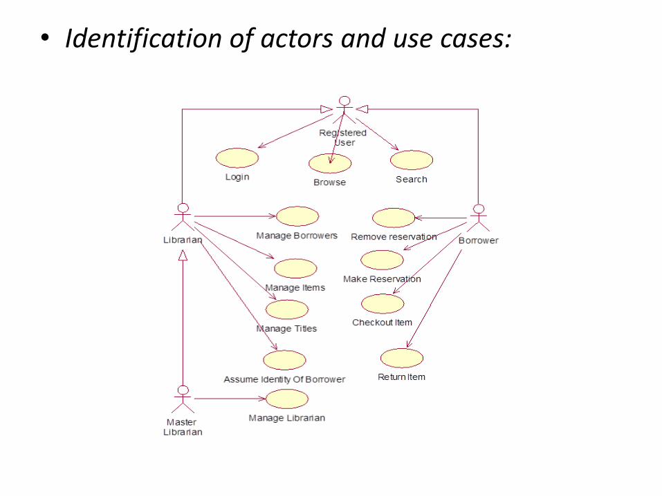
• Identification of actors and use cases:
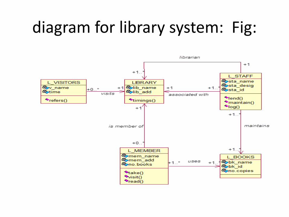
diagram for library system: Fig:

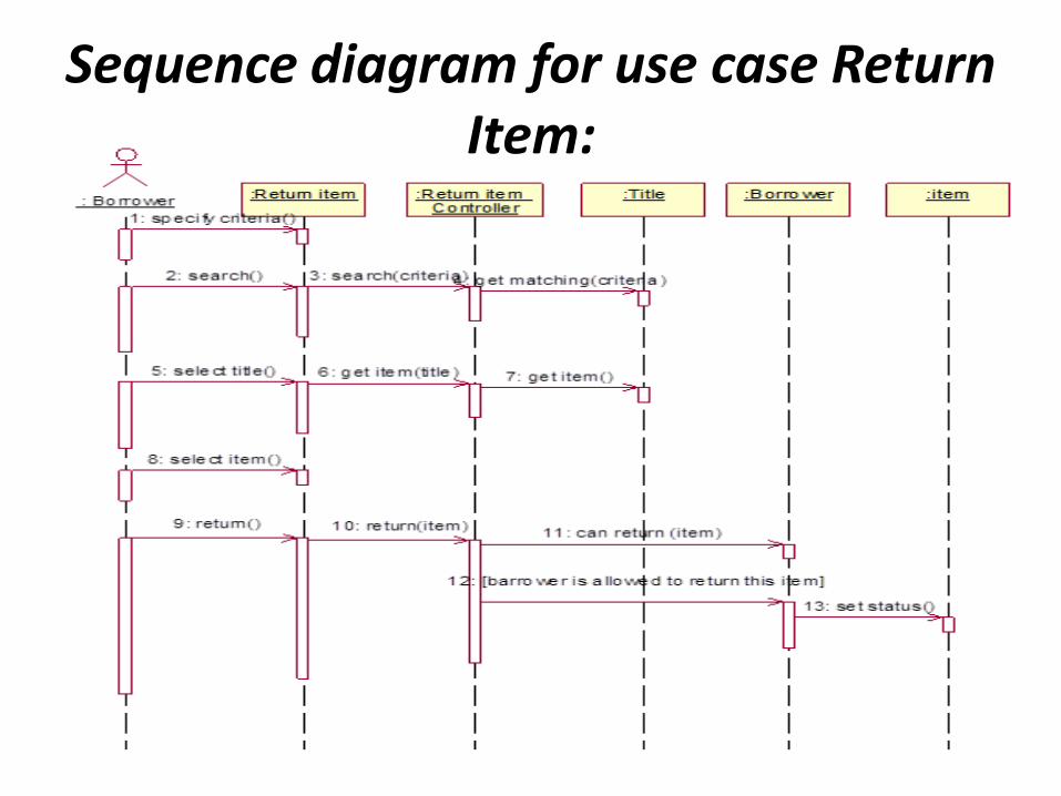
Sequence diagram for use case Return Item:
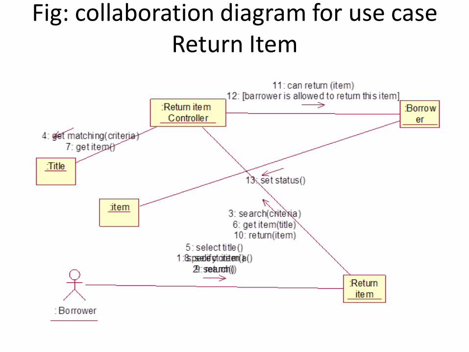
Fig: collaboration diagram for use case Return Item
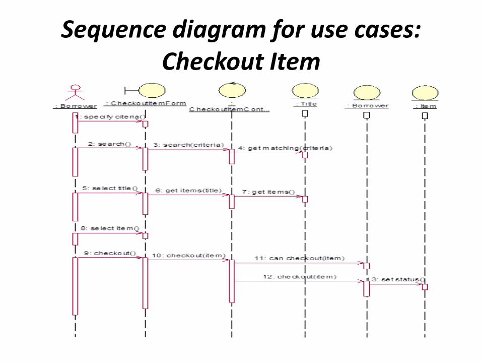
Sequence diagram for use cases: Checkout Item

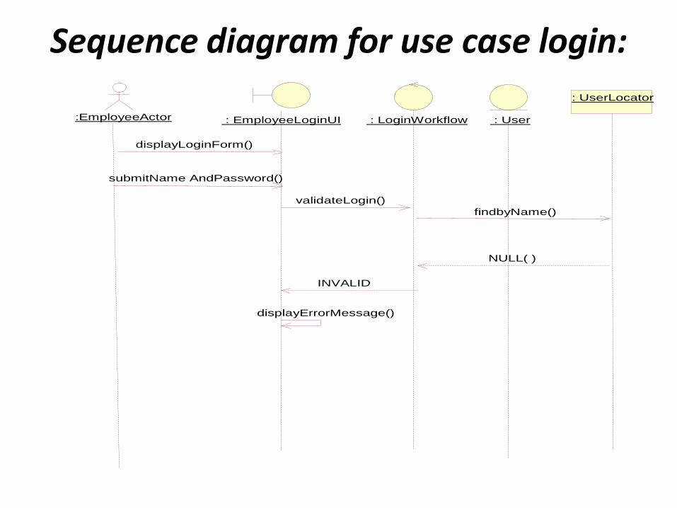
Sequence diagram for use case login:
:EmployeeActor : LoginWorkflow : User
: UserLocator
: EmployeeLoginUI
findbyName()
NULL( )
displayLoginForm()
submitName AndPassword()
validateLogin()
INVALID
displayErrorMessage()

Fig: collaboration diagram for login
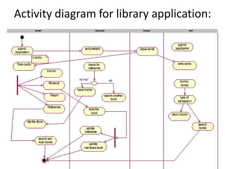
Activity diagram for library application:

STATE MACHINE DIAGRAM FOR THE TITLE CLASS:

STATE DIAGRAM FOR LIBRARY SYSTEM

Component diagram for library application:
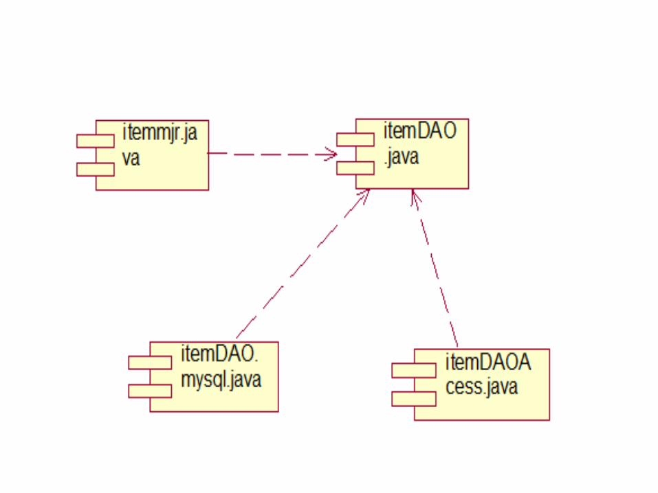
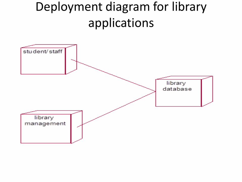
Deployment diagram for library applications