object follower bot
TRANSCRIPT

Object Follower Bot
Project Report Submitted in Partial Fulfillment of the Requirement for
The Project Of Mechatronics
in
Mechanical Engg. of
Aiktc , New Panvel
By
13ME80 KHAN FAHAD
13ME106 SEIKH FARHAN
13ME107 MUKADAM SHAFIQUE
14DME UMAR ANSARI

DECLARATION
We, Khan Fahad, seikh farhan, Mukadam Shafique and Umar Ansari the
students of T.e M.e 2 , hereby declare that the work presented in this Minor
Project is an authentic record of our own and has been carried out taking care of
Engineering Ethics under the guidance of Prof. Arshad qureshi
Khan Fahad (13me80) ………………………
Seikh Farhan (13me106) ………………………
Mukadam Shafique (13me107) ………………………
Umar Ansari (14dme) ………………………
ii

CERTIFICATE
This is to certify that the work embodied in this Minor Project entitled
“Object follower Robot” has been satisfactorily completed by the students of third
year, Mr Khan fahad , Mr. Seikh Farhan , Mr. Mukadam Shafique And Mr. Umar
Ansari . The work was carried out satisfactorily under the supervision and
guidance of the undersigned in the Department of Mechanical Engineering, Aiktc
, New Panvel for the partial fulfillment of the requirement of degree of Bachelor
of Engineering during the Academic year 2015-2016.
Prof. Arshad Qureshi
Professor and Project Guide,
Mechanical Department
Approved
Prof. Zakir Ansari Dr. Abdul Razzak
Head of Department Director
iii
ACKNOWLEDGEMENT

CONTENTS
DECLARATION … ii
CERTIFICATE … iii
1. INTRODUCTION … 01
2. REWVIEW OF LITERATURE … 05
2.1 Construction … 07
2.1.1 Hardware Unit … 07
2.1.2 Software Unit … 13
2.2 Basic Parts Of Project …29
2.2.1 Sensors … 29
2.2.2 Microcontroller … 29
2.2.3 Driver … 30
2.2.4 Motors … 30
2.3 Problem Faced In Making Project … 31
2.4 Testing … 32
2.5 Applications … 33
2.6 Future Scope By Improvement … 33
3. COMPONENTS … 34
3.1 Microcontroller ATMEGA8L … 35
3.2 IC L293D … 36
3.3 IC LM324N … 37
3.4 IC 7805 … 38
3.5 Resistor … 38
3.6 IR LED … 39
3.7 Photodiode … 40
4. RESULTS … 41
5. REFERENCES ... 42
6. APPENDICES … 43
6.1 Datasheet … 43
6.2 Program …48

LIST OF FIGURS
Figure 2.1 Block Diagram of Project ... 06
Figure 2.2 IR Sensor circuit ... 10
Figure 2.3 Controller Circuit ... 12
Figure 2.4 PCB layout of sensor …18
Figure 2.5 PCB of Controller Circuit ... 19
Figure 2.6 Final PCB Layout ... 20
Figure 3.1 Microcontroller ATMEGA8L ... 35
Figure 3.2 IC L293D ... 36
Figure 3.3 IC LM324N … 37
Figure 3.4 IC 7805 … 38
Figure 3.5 Resistor … 39
Figure 3.6 IR LED … 39
Figure 3.7 Photodiode … 40
Figure 6.1 ATMEGA8L Pin Diagram … 45
Figure 6.2 IC 7805 Pin Diagram … 46
Figure 6.3 IC LM324N Pin Diagram … 47
Figure 6.4 IC 293 Pin Diagram … 48

1. INTRODUCTION
Robotics is part of Today’s communication. In today’s world
ROBOTICS is fast growing and interesting field. It is simplest way for latest
technology modification. Now a day’s communication is part of advancement of
technology, so we decided to work on robotics field, and design something which
will make human life simpler in day today aspect. Thus we are supporting this
cause.
Robotics is the branch of technology that deals with the design,
construction, operation, structural disposition, manufacture and application of
robots and computer systems for their control, sensory feedback, and information
processing.
Obstacle detection and avoidance robots are intelligent robots which
can perform desired tasks in unstructured environments by finding and
overcoming obstacles in their way without continuous human guidance.
In robotics, obstacle avoidance is the task of satisfying some control
objective subject to non-intersection or non-collision position constraints.
Normally obstacle avoidance is considered to be distinct from path planning in
that one is usually implemented as a reactive control law while the other involves
the pre-computation of an obstacle-free path which a controller will then guide a
robot along. A practical real-time system for passive obstacle detection and
avoidance is presented.
Robot Sensors are essential components in creating autonomous robots
as they are the only means for a robot to detect information about itself and its
environment. As little as one sensor is needed by a robot, though increasing the
number and variety of sensors tends to increase the robot’s ability to get a more
thorough understanding of the world around it.
There are a wide variety of sensors available which are capable of
measuring almost anything, from environmental conditions (distance, light,
sound, temperature) to angular and linear acceleration, forces and distances. The
01

first sensor often incorporated into a mobile robot is a distance sensor, which is
usually in the form of an infrared or ultrasonic sensor. In both cases, a pulse (of
light or sound) is sent and its reflection is timed to get a sense of distance. Usually
these values are sent to the controller many times each second.
Robot Shop offers a wide variety of sensors applicable to almost any
robotics project. If you are looking for a distance sensor, we offer them in a
variety of configurations and optimal distances to suit almost any budget. If you
are looking for a more professional solution for measuring distances, take a look
at our selection of scanning laser rangefinders, which are able to scan over >180
degrees (and less than 1 degree of accuracy) in well under 1 second.IR Pair is
used as sensor to detect the presence of objects. IR LED is used for detecting
objects.
In this project mainly when ever robot senses any obstacle
automatically diverts its position to left or right and follows the path. Robot
consists of two motors, which control the side pair wheels of each and help in
moving forward and backward direction. Robot senses the object with help of
obstacle sensor. IR pair is used for detecting the obstacle. The two basic parts for
working with IR are the emitter and the detector. The emitter is typically an LED
that emits near-infrared light.
Infrared (IR) light is electromagnetic radiation with a wavelength
longer than that of visible light, measured from the nominal edge of visible red
light at 0.74 micrometers (µm), and extending conventionally to 300 µm. These
wavelengths correspond to a frequency range of approximately 1 to 400 THz, and
include most of the thermal radiation emitted by objects near room temperature.
Microscopically, IR light is typically emitted or absorbed by molecules when they
change their rotational-vibration movements.
Infrared light is used in industrial, scientific, and medical applications.
Night-vision devices using infrared illumination allow people or animals to be
observed without the observer being detected. In astronomy, imaging at infrared
wavelengths allows observation of objects obscured by interstellar dust. Infrared
02

Imaging cameras are used to detect heat loss in insulated systems, observe
changing blood flow in the skin, and overheating of electrical apparatus.
IR LED IR detectors are specially filtered for Infrared lighted are not
good at detecting visible light. On the other hand, photocells are good at detecting
yellow/green visible light, not well at IR light.
IR detectors have a demodulator inside that looks for modulated IR at
38 KHz. Just shining an IR LED won’t be detected, it has to be PWM blinking at
38KHz. Photocells do not have any sort of demodulator and can detect any
frequency (including DC) within the response speed of the photocell (which is
about 1KHz). IR detectors are digital out - either they detect 38KHz IR signal
and output low (0V) or they do not detect any and output high (5V). Photocells
act like resistors, the resistance changes depending on how much light they are
exposed to.
A photodiode is a type of photo detector capable of converting light
into either current or voltage, depending upon the mode of operation. The
common, traditional solar cell used to generate electric solar power is a large area
photodiode.
Photodiodes are similar to regular semiconductor diodes except that
they may be either exposed (to detect vacuum UV or X-rays) or packaged with a
window or optical fiber connection to allow light to reach the sensitive part of the
device. Many diodes designed for use specifically as a photodiode use a PIN
junction rather than a p-n junction, to increase the speed of response. A
photodiode is designed to operate in reverse bias. In this project we develop a
robot such that it will be moving according to path assigned to it if at all there is
any obstacle in between then the robot stops and change its direction. This sort of
project is very much useful in the industries where the automated supervision is
required.
This project is basic stage of any automatic robot. This robot has
sufficient intelligence to cover the maximum area of provided space. It has a
infrared sensor which are used to sense the object coming in between the path of
robot. It will move in a particular direction and Follow the Object which is
coming in its path.
03

A robot object follower system comprising: a robot housing which
navigates with respect to a surface; a sensor subsystem having a defined
relationship with respect to the housing and aimed at the surface for detecting the
surface, the sensor subsystem including: an optical emitter which emits a directed
beam having a defined field of emission, and a photon detector having a defined
field of view which intersects the field of emission of the emitter at a finite
region; and a circuit in communication with the detector for redirecting the robot
when the surface does not occupy the region to avoid follow object.
Object sensors are nothing but the IR pair. As the transmitter part
travel IR rays from to receiver here also transmitter send the data receiver but
these IR pair are places beside each other. So whenever an object sensor got a
obstacle in between its way the IR rays reflects in a certain angle. As they are
placed side by each.
We have used two D.C motors to give motion to the robot. The
construction of the robot circuit is easy and small .The electronics parts used in
the robot circuits are easily available and cheap too.
04
2. REVIEW OF LITERATURES
This robot has sufficient intelligence to cover the maximum area of
provided space. It has an infrared sensor which is used to sense the obstacles
coming in between the path of robot. It will move in a particular direction and
avoid the obstacle which is coming in its path.
It uses IR (Infra Red) sensors and two IR transmitting circuitry. When
the obstacle comes in path of robot IR beam is reflected from the obstacle then
sensor gives zero voltage to µc. This zero voltage is detected then µc decides to
avoid the obstacle by taking left or right turn. If the sensor gives +5v to µc that
means there is no obstacle present in its path so it goes straight until any obstacle
is detected.
The two IR transmitter circuits are fitted on front and left side of
robot. The two IR sensors are placed near to transmitters’ IR LEDs. The
connections can be given from main circuit to sensors using simple twisted pair
cables. Two motors namely right motor and left motor are connected to driver IC
(L293D). L293D is interface with µc. Micro-controller sends logic 0 & logic 1 as
per the programming to driver IC which moves motors forward or reverse
direction. Now let us see all the things in our project.
05

Figure 2.1: Block Diagram of Project
06

2.1 Construction
The project is combination of different units as follows:
1. Hardware
2. Software
2.1.1 Hardware Unit
The hardware part includes the structure of robot that is Electronics and
Communication structure, PCB (printed circuit board), blower, and battery. In this
unit all the connections are being made along with the PCB now let us see in brief
how it can be done.
2.1.1.1 Electronics and Communication Connection
In Electronics and Communication connection wheel is connected to base very
tightly to avoid errors in the system. Connection of blower is made with lower
part of base and battery is connected in upper portion of base for power supply to
the system which is very important battery used here is of 6v battery, blower of
+5V to +9V. And along with wheel electrical motors are connected with base
having r.p.m of 100 rpm.
2.1.1.2 PCB Connection
A printed circuit board, or PCB, is used to Electronics and Communicationly
support and electrically connect electronic components using conductive pathways,
tracks or signal traces etched from copper sheets laminated onto a non-conductive
substrate.
The PCB is printed circuit board having circuit made with cooper
layer on the plate there are various steps to design a PCB for that the basic thing
required is circuit. So, the circuits required for the system are:
07
2.1.1.2.1 IR Sensor Circuit
An infrared sensor is an electronic device that emits and/or detects infrared
radiation in order to sense some aspect of its surroundings. Infrared sensors can
measure the heat of an object, as well as detect motion. Many of these types of
sensors only measure infrared radiation, rather than emitting it, and thus are
known as passive infrared (PIR) sensors.
All objects emit some form of thermal radiation, usually in the infrared
spectrum. This radiation is invisible to our eyes, but can be detected by an
infrared sensor that accepts and interprets it. In a typical infrared sensor like a
motion detector, radiation enters the front and reaches the sensor itself at the center
of the device. This part may be composed of more than one individual sensor,
each of them being made from piezoelectric materials, whether natural or
artificial.
IR Sensor includes photodiode and IR LED which play the role of
receiver and transmitter respectively.
2.1.1.2.1.1 IR LED
An IR LED, also known as IR transmitter, is a special purpose LED that transmits
infrared rays in the range of 760 nm wavelength. Such LEDs are usually made of
gallium arsenide or aluminum gallium arsenide. They, along with IR receivers,
are commonly used as sensors.
The appearance is same as a common LED. Since the human eye
cannot see the infrared radiations, it is not possible for a person to identify
whether the IR LED is working or not, unlike a common LED. To overcome this
problem, the camera on a cell phone can be used. The camera can show us the IR
rays being emanated from the IR LED in a circuit.
08

2.1.1.2.1.2 Photodiode
A photodiode is a type of photo detector capable of converting light into either
current or voltage, depending upon the mode of operation. The common,
traditional solar cell used to generate electric solar power is a large area
photodiode. It is use to sense the reflected IR rays which reflect due to presence of
obstacle and due to it robot change its path.
This sensor uses IR (Infra Red) sensors and two IR transmitting
circuitry. When the obstacle comes in path of robot IR beam is reflected from the
obstacle then sensor gives zero voltage to µc. This zero voltage is detected then
µc decides to avoid the obstacle by taking left or right turn. If the sensor gives
+5v to µc that means there is no obstacle present in its path so it goes straight
until any obstacle is detected. The sensor circuit is shown in figure 2.2.
It uses IR (Infra Red) sensors and two IR transmitting circuitry. When
the obstacle comes in path of robot IR beam is reflected from the obstacle then
sensor gives zero voltage to µc. This zero voltage is detected then µc decides to
avoid the obstacle by taking left or right turn. If the sensor gives +5v to µc that
means there is no obstacle present in its path so it goes straight until any obstacle
is detected.
The two IR transmitter circuits are fitted on front and left side of
robot. The two IR sensors are placed near to transmitters’ IR LEDs. The
connections can be given from main circuit to sensors using simple twisted pair
cables.
09

Figure 2.2: IR Sensor circuit
10

After having the circuit it is easy to design PCB. Circuit is traced in PCB by using
different software here we have used PCB Express software to design layout then
it is etched and further the component are soled in it.
2.1.1.2.2 Controller Circuit
A microcontroller (sometimes abbreviated µC, uC or MCU) is a small computer
on a single integrated circuit containing a processor core, memory, and
programmable input/output peripherals.
Microcontrollers are used in automatically controlled products and
devices, such as automobile engine control systems, implantable medical devices,
remote controls, office machines, appliances, power tools, toys and other
embedded systems. By reducing the size and cost compared to a design that uses a
separate microprocessor, memory, and input/output devices, microcontrollers
make it economical to digitally control even more devices and processes. Mixed
signal microcontrollers are common, integrating analog components needed to
control non-digital electronic systems.
Here we are giving code to Microcontroller according to those codes
our robot move; these codes are created by programming logic in Keil software
and latter burn in microcontroller by flash magic software. These codes control
the motor by the logic of 0 and by logic 1 and through this direction of robot is
control.
But for the purpose of providing this logic to motor we use an IC that
is L293D Having 16 pin it get input by output of microcontroller this make robot
an intelligent or autonomous robot this IC also amplifies the current and provide
to motor .
11

Figure 2.3: Controller Circuit
12

After having the circuit it is easy to design PCB. Circuit is traced in PCB by using
different software here we have used PCBExpress software to design layout then
it is etched and further the component are solded in it.
Now when all the PCBs are connected according to required condition
and the electro-Electronics and Communication structure is ready still the system
will not work without software unit.
Let us discuss the software unit.
2.1.2 Software Unit
Computer software or just software is a collection of computer programs and
related data that provides the instructions for telling a computer what to do and
how to do it. Software refers to one or more computer programs and data held in
the storage of the computer for some purposes. In other words, software is a set of
programs, procedures, algorithms and its documentation concerned with the
operation of a data processing system. Program software performs the function of
the program it implements, either by directly providing instructions to the
computer hardware or by serving as input to another piece of software.
The term was coined to contrast to the old term hardware (meaning
physical devices). In contrast to hardware, software "cannot be touched".
Software is also sometimes used in a more narrow sense, meaning application
software only. Sometimes the term includes data that has not traditionally been
associated with computers, such as film, tapes, and records.
28

2.2 Basic Parts Of Project
So, now we may say that there are following main parts are there used
in our projects those are:
2.2.1 Sensors
A sensor (also called detector) is a converter that measures a physical
quantity and converts it into a signal which can be read by an observer or by an
(today mostly electronic) instrument.
Sensors are used in everyday objects such as touch-sensitive elevator
buttons (tactile sensor) and lamps which dim or brighten by touching the base.
There are also innumerable applications for sensors of which most people are
never aware. Applications include cars, machines, aerospace, medicine ,
manufacturing and robotics.
The IR Transmitter block mainly used to generate IR signal. It uses
timer IC555 in astable multivibrator mode to generate square wave which have
continuous pulses of 50% duty cycle of frequency 38 KHz. This transmitter is so
arranged that the IR rays are focused on the sensor.
2.2.2 Microcontroller
This is the most important block of the system. Microcontroller is the
decision making logical device which has its own memory, I/O ports, CPU and
Clock circuit embedded on a single chip.
A microcontroller (sometimes abbreviated µC, uC or MCU) is a small
computer on a single integrated circuit containing a processor core, memory, and
programmable input/output peripherals. Program memory in the form of NOR
flash or OTP ROM is also often included on chip, as well as a typically small
amount of RAM. Microcontrollers are designed for embedded applications, in
contrast to the microprocessors used in personal computers or other general
purpose applications.

29
Microcontrollers are used in automatically controlled products and
devices, such as automobile engine control systems, implantable medical devices,
remote controls, office machines, appliances, power tools, toys and other
embedded systems.
By reducing the size and cost compared to a design that uses a separate
microprocessor, memory, and input/output devices, microcontrollers make it
economical to digitally control even more devices and processes. Mixed signal
microcontrollers are common, integrating analog components needed to control
non-digital electronic systems
2.2.3 Driver
L293D is used as driver IC. Motors are connected to this IC. According to
program in µc it drives the left and right motor. L293D is a dual H-bridge motor
driver integrated circuit (IC). Motor drivers act as current amplifiers since they
take a low-current control signal and provide a higher-current signal. This higher
current signal is used to drive the motors.
L293D contains two inbuilt H-bridge driver circuits. In its common
mode of operation, two DC motors can be driven simultaneously, both in forward
and reverse direction. The motor operations of two motors can be controlled by
input logic at pins 2 & 7 and 10 & 15. Input logic 00 or 11 will stop the
corresponding motor. Logic 01 and 10 will rotate it in clockwise and
anticlockwise directions, respectively.
Enable pins 1 and 9 (corresponding to the two motors) must be high
for motors to start operating. When an enable input is high, the associated driver
gets enabled. As a result, the outputs become active and work in phase with their
inputs. Similarly, when the enable input is low, that driver is disabled, and their
outputs are off and in the high- impedance state.
2.2.4 Motors
An electric motor is an electromechanical device that converts electrical energy
into mechanical energy.

30
Most electric motors operate through the interaction of magnetic fields
and current-carrying conductors to generate force.
The reverse process, producing electrical energy from mechanical
energy, is done by generators such as an alternator or a dynamo; some electric
motors can also be used as generators, for example, a traction motor on a vehicle
may perform both tasks. Electric motors and generators are commonly referred to
as electric machines.
2.3 Problem Faced In Making Project
Although the concept & design of the project seemed perfect, there were
some problems faced while actual implementation:
2.3.1 Proving Proper Power to different circuit
Solution: taking high precaution in designing of circuit.
2.4 Testing
There is always necessary to check the work for that here we have
implemented various test for following:
2.4.1 Continuity test
First of all we checked the PCB that all the tracks are as per the design
of PCB and showing continuity with the help of multimeter and PCB layout.
2.4.2 Short circuit test
Then we checked the PCB for any unwanted short circuits with the
help of multimeter and PCB layout.
2.4.3 Soldering
In the next step, we soldered the required components. And then
checked that there are no any unwanted shorts occurred due to soldering without
putting IC's and keeping power supply off.

2.4.4 Power supply test
In the next step, we put power supply on and checked whether
required voltage is appearing at the required voltage is appearing at the required
points i.e.+Vcc and GND at the respective points. We took care of not connecting
IC's in the circuit while performing this test.
2.4.5 Microcontroller test
For testing the microcontroller, we wrote the square wave generation
program for generating square wave on each port pin. Then we fed the program in
microcontroller and checked the output with the help of CRO by connecting the
microcontroller in the circuit. We took care of not connecting any other IC in the
circuit.
32
2.5 Applications
There are following application of Object Follower robot
1) This logic has been specially designed for _______ . By using heavy rating
motors, strong mechanical structure and using highly sensitive obstacle sensors, it
efficiently works as________.
2) Just by making small changes in software this system can be used for avoiding
concealed paths. This robot can effectively sense the obstacles and find out
correct path.
3) With proper programming we can use it as a______.
4) In Mines.
2.6 Future Scope By Improvement
The future uses of IR obstacle detector are as follows:

2.6.1 Adding a Camera:
If the current project is interfaced with a camera (e.g. a Webcam) robot
can be driven beyond line-of-sight & range becomes practically unlimited as
networks have a very large range.
2.6.2 Use as a fire fighting robot:
By adding temperature sensor, water tank and making some changes in
programming we can use this robot as fire fighting robot.
33
3. COMPONENTS
An electronic component is a basic electronic element that is available in a
discrete form (a discrete device or discrete component) that has two or more
electrical terminals (or leads). These leads connect, usually soldered to a printed
circuit board, to create an electronic circuit (a discrete circuit) with a particular
function (for example an amplifier, radio receiver, or oscillator). Basic electronic
components may be packaged discretely, as arrays or networks of like
components, or integrated inside of packages such as semiconductor integrated
circuits, hybrid integrated circuits, or thick film devices. The following list of
electronic components focuses on the discrete version of these components,
treating such packages as components in their own right.
So the components used in our project are:
1. Microcontroller ATMEGA8L
2. IC 293D

3. IC LM324N
4. IC 7805
5. Potentiometer 20k
6. Resistor 1k ohm
7. IR LED
8. Photo diode
9. Battery
10. Soldering wire
Let us discuss all components in brief
34
3.1. Microcontroller ATMEGA8L
The ATmega8 is a low-power CMOS 8-bit microcontroller based on the AVR
RISC architecture. By executing powerful instructions in a single clock cycle, the
ATmega8 achieves throughputs approaching 1 MIPS per MHz, allowing the
system designer to optimize power consumption versus processing speed.

Fig 3.1 Microcontroller ATMEGA8L
ATMEGA8L Features:
High-performance, Low-power AVR® 8-bit Microcontroller Advanced RISC
Architecture
– 130 Powerful Instructions – Most Single-clock Cycle Execution
– 32 x 8 General Purpose Working Registers
– Fully Static Operation
Nonvolatile Program and Data Memories
– 8K Bytes of In-System Self-Programmable Flash
In-System Programming by On-chip Boot Program
Special Microcontroller Features
– Power-on Reset and Programmable Brown-out Detection
– Internal Calibrated RC Oscillator
– External and Internal Interrupt Sources
35
I/O and Packages
– 23 Programmable I/O Lines
– 28-lead PDIP, 32-lead TQFP, and 32-pad MLF
Operating Voltages 2.7 - 5.5V (ATmega8L)

3.2 IC L293D
L293D is a dual H-bridge motor driver integrated circuit (IC). Motor drivers act
as current amplifiers since they take a low-current control signal and provide a
higher-current signal. This higher current signal is used to drive the motors.
Fig 3.2 IC L293D
L293D contains two inbuilt H-bridge driver circuits. In its common mode of
operation, two DC motors can be driven simultaneously, both in forward and
reverse direction. The motor operations of two motors can be controlled by
input logic at pins 2 & 7 and 10 & 15. Input logic 00 or 11 will stop the
corresponding motor. Logic 01 and 10 will rotate it in clockwise and
anticlockwise directions, respectively. Enable pins 1 and 9 (corresponding to
36
the two motors) must be high for motors to start operating. When an enable
input is high, the associated driver gets enabled.
As a result, the outputs become active and work in phase with
their inputs. Similarly, when the enable input is low, that driver is disabled, and
their outputs are off and in the high-impedance state.

3.3 IC LM324N
LM324 is a 14pin IC consisting of four independent operational amplifiers (op-
amps) compensated in a single package. Op-amps are high gain electronic voltage
amplifier with differential input and, usually, a single-ended output. The output
voltage is many times higher than the voltage difference between input terminals
of an op-amp.
Fig 3.3 IC LM324N
These op-amps are operated by a single power supply LM324 and need
for a dual supply is eliminated. They can be used as amplifiers, comparators,
oscillators, rectifiers etc. The conventional op-amp applications can be more
easily implemented with LM324.
37
3.4 IC 7805
Fixed voltage Positive and Negative regulator ICs are used in circuits to give
precise regulated voltage.78 XX series regulator IC can handle maximum 1
ampere current. The Regulator ICs require minimum 1.5 higher input voltage than
their voltage rating. For example 7805 IC requires minimum 6.5 volts to give 5

volt output. Here are some circuit designs of IC 7805 to monitor the output
voltage.
Fig 3.4 IC 7805
3.5 Resistor
A resistor is a passive two-terminal electrical component that implements
electrical resistance as a circuit element. The current through a resistor is in direct
proportion to the voltage across the resistor's terminals. Thus, the ratio of the
voltage applied across a resistor's terminals to the intensity of current through the
circuit is called resistance.
V= IR
where I is the current through the conductor in units of amperes, V is
the potential difference measured across the conductor in units of volts, and R is
the resistance of the conductor in units of ohms. More specifically, Ohm's law
states that the R in this relation is constant, independent of the current.
38
Resistors are common elements of electrical networks and electronic
circuits and are ubiquitous in electronic equipment. Practical resistors can be
made of various compounds and films, as well as resistance wire (wire made of a
high-resistivity alloy, such as nickel-chrome). Resistors are also implemented

within integrated circuits, particularly analog devices, and can also be integrated
into hybrid and printed circuits.
Fig 3.5 RESISTOR
3.6 IR LED
An IR LED, also known as IR transmitter, is a special purpose LED that transmits
infrared rays in the range of 760 nm wavelength. Such LEDs are usually made of
gallium arsenide or aluminum gallium arsenide. They, along with IR receivers,
are commonly used as sensors.
Fig 3.6 IR LED
39
The appearance is same as a common LED. Since the human eye
cannot see the infrared radiations, it is not possible for a person to identify
whether the IR LED is working or not, unlike a common LED. To overcome this
problem, the camera on a cell phone can be used. The camera can show us the IR
rays being emanated from the IR LED in a circuit.
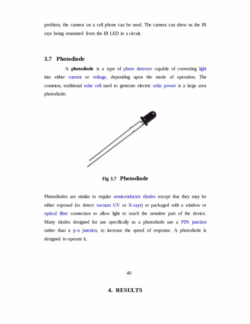
3.7 Photodiode
A photodiode is a type of photo detector capable of converting light
into either current or voltage, depending upon the mode of operation. The
common, traditional solar cell used to generate electric solar power is a large area
photodiode.
Fig 3.7 Photodiode
Photodiodes are similar to regular semiconductor diodes except that they may be
either exposed (to detect vacuum UV or X-rays) or packaged with a window or
optical fiber connection to allow light to reach the sensitive part of the device.
Many diodes designed for use specifically as a photodiode use a PIN junction
rather than a p-n junction, to increase the speed of response. A photodiode is
designed to operate it.
40
4. RESULTS

Thus, we believe that our project will be beneficial for various purposes & hence
our efforts will be fruitful. So, we made a successfully obstacle detector robot
having application of vacuum cleaner which have ability to move freely anywhere
and along with it, it have ability to create its own path and it avoid obstacle by
artificial intelligence provided by programming in microcontroller to perform
action and IR sensor to sense the obstacle, it also clean the area where it move
with vacuum cleaner which is its application.
41
5. REFERENCES

1. "Atmel’s Self-Programming Flash Microcontrollers" by Odd Jostein
Svendsli 2003
2. http://www.semico.com
3. Heath, Steve (2003). Embedded systems design. EDN series for design
engineers (2 ed.). Newnes. pp. 11–12. ISBN 9780750655460.
4. Easy Way to build a microcontroller project
5. Robert Edwards (1987). "Optimizing the Zilog Z8 Forth Microcontroller
for Rapid Prototyping". p. 3.
6. www.infineon.com/mcu
42
6. APPENDICES

6.1 Datasheet
6.1.1 ATMEGA8L
6.1.2 IC 7805
6.1.3 IC LM324N
6.1.4 IC 293D
6.1.1 ATMEGA8L
1. Introduction
• High-performance, Low-power Atmel®AVR® 8-bit Microcontroller
• Advanced RISC Architecture
– 130 Powerful Instructions – Most Single-clock Cycle Execution
– 32 × 8 General Purpose Working Registers
– Fully Static Operation
– Up to 16MIPS Throughput at 16MHz
– On-chip 2-cycle Multiplier
• High Endurance Non-volatile Memory segments
– 8Kbytes of In-System Self-programmable Flash program memory
– 512Bytes EEPROM
– 1Kbyte Internal SRAM
– Write/Erase Cycles: 10,000 Flash/100,000 EEPROM
– Data retention: 20 years at 85°C/100 years at 25°C
– Optional Boot Code Section with Independent Lock Bits
2. In-System Programming by On-chip Boot Program
3. True Read-While-Write Operation
– Programming Lock for Software Security
• Peripheral Features
– Two 8-bit Timer/Counters with Separate Prescaler, one Compare Mode
– One 16-bit Timer/Counter with Separate Prescaler, Compare Mode, and
Capture
43
2. Mode

– Real Time Counter with Separate Oscillator
– Three PWM Channels
– 8-channel ADC in TQFP and QFN/MLF package
3. Eight Channels 10-bit Accuracy
– 6-channel ADC in PDIP package
4. Six Channels 10-bit Accuracy
– Byte-oriented Two-wire Serial Interface
– Programmable Serial USART
– Master/Slave SPI Serial Interface
– Programmable Watchdog Timer with Separate On-chip Oscillator
– On-chip Analog Comparator
• Special Microcontroller Features
– Power-on Reset and Programmable Brown-out Detection
– Internal Calibrated RC Oscillator
– External and Internal Interrupt Sources
– Five Sleep Modes: Idle, ADC Noise Reduction, Power-save, Power-down,
and
5. Standby
• I/O and Packages
– 23 Programmable I/O Lines
– 28-lead PDIP, 32-lead TQFP, and 32-pad QFN/MLF
• Operating Voltages
– 2.7V - 5.5V (ATmega8L)
– 4.5V - 5.5V (ATmega8)
• Speed Grades
– 0 - 8MHz (ATmega8L)
– 0 - 16MHz (ATmega8)
• Power Consumption at 4Mhz, 3V, 25°C
– Active: 3.6mA
– Idle Mode: 1.0mA
44
6. 8-bit
7. with 8KBytes

8. In-System
9. Programmable
10. Flash
Fig 6.1 ATMEGA8L PIN DIAGRAM
6.1.2 IC 7805
1. Internal Thermal Overload Protection.
2. Internal Short Circuit Current Limiting.
3. Output Current up to 1.5A.
4. Satisfies IEC-65 Specification. (International Electronical Commission).
5. Package is TO
45

Fig 6.2 IC 7805 PIN DIAGRAM
6.1.3 IC LM324N
• Internally frequency-compensated for unity gain
• Large DC voltage gain: 100dB
• Wide bandwidth (unity gain): 1MHz (temperature-compensated)
• Wide power supply range Single supply: 3VDC to 30VDC or dual
Supplies: ±1.5VDC to ±15VDC
• Very low supply current drain: essentially independent of supply
Voltage (1mW/op amp at +5VDC)
• Low input biasing current: 45nADC (temperature-compensated)
• Low input offset voltage: 2mVDC and offset current: 5nADC
• Differential input voltage range equal to the power supply voltage
• Large output voltage: 0VDC to VCC-1.5VDC swing
46

Fig 6.3 LM324N PIN DIAGRAM
6.1.4 IC 293D
• Terminations: 100 % matte tin, standard, tin/lead available
• Compliant terminations
• Molded case available in six case codes
• Compatible with “High Volume” automatic pick and place equipment
• Optical character recognition qualified
• Meets IEC specification QC300801/US0001 and
EIA535BAAC mechanical and performance requirements
• Compliant to RoHS Directive 2002/95/EC
• Moisture sensitivity level 1
47

Fig 6.4 IC 293 PIN DIAGRAM
6.2 Program
50