obd data logger user manual - dg tech
TRANSCRIPT
OBD Data Logger User Manual
© 2020 DG Technologies
Document 1.0
Document Date: December 2020
DG Technologies 33604 West Eight Mile Road Farmington Hills, MI 48335 Phone (248) 888-2000 Fax (248) 888-9977
Page | 2
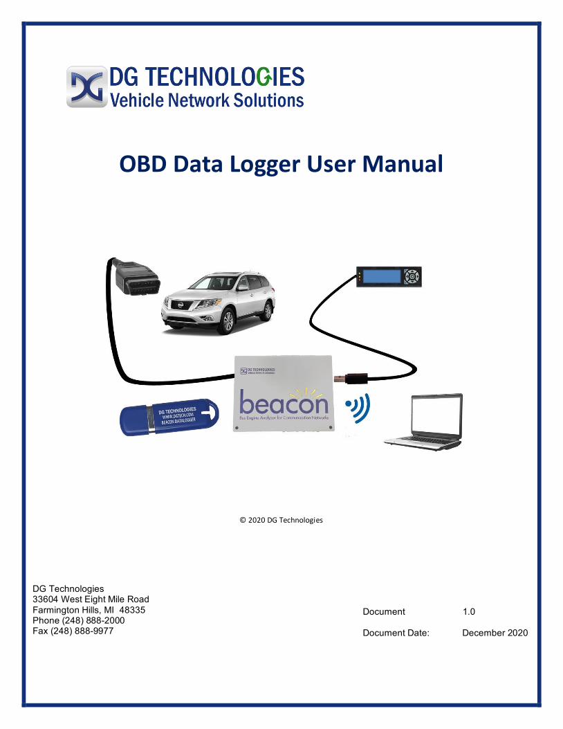
This document describes DG Technologies On-Board Diagnostics (OBD) Data Logger. The OBD Data Logger collects digital message data from a vehicle network for various types of analysis, such as vehicle performance, cost efficiency, problem diagnosis or network development work.
This comprehensive data logger can simultaneously collect digital OBD and ECU message data along with analog or digital signals from sensors and actuators. This provides a complete picture of what is happening in the vehicle for analysis or diagnosis of the user’s specific concerns.
Permission is granted to copy any or all portions of this manual, provided that such copies are for use with OBD Data Logger product and that “© 2020 DG Technologies.”, (herein referred to as “Dearborn Group”, “DG Technologies”, or “DG”), remains on all copies.
The accompanying software, provided for use with the OBD Data Logger, is also copyrighted. Permission is granted to copy this software for back-up purposes only.
I M P O R T A N T
To ensure your success with this product, it is essential that you read this document carefully before using the hardware.
Damage caused by misuse of the hardware is not covered under product warranty. When using this manual, please remember the following:
• This manual may be changed, in whole or in part, without notice. • DG assumes no responsibility for any damage resulting from the use of this
hardware or software. • Specifications presented herein are provided for illustration purposes only and
may not accurately represent the latest revisions of hardware, software or cabling. • No license is granted, by implication or otherwise, for any patents or other rights
of DG or of any third party.
DG® logo is a registered trademark of DG Technologies, Inc. Other products that may be referenced in this manual are trademarks of their respective manufacturers.
© 2020 DG Technologies
Page | 3
Introduction ................................................................................................ 4
OBD Data Logger Overview ...................................................................... 7
Standard Usage - Loading Instructions ................................................................................................... 8
Data Monitor Screen.............................................................................................................................. 8
Menu Screen ......................................................................................................................................... 8
Menu Buttons ........................................................................................................................................ 9
Menu Buttons Functions........................................................................................................................ 9
LED Functions ...................................................................................................................................... 10
Set-Up and Loading Instructions ............................................................ 10
Optional Trip Limit Sequence ............................................................................................................... 10
Ability to Lock and Unlock the Module ................................................................................................ 10
DiagRA X .............................................................................................................................................. 11
DiagRA X Process Illustration ............................................................................................................... 12
After DiagRA X Configuration/Process ................................................................................................. 12
Possible Trigger Modes ........................................................................................................................ 13
Road Test Procedure............................................................................................................................ 13
Data Monitor ....................................................................................................................................... 14
Error Codes .......................................................................................................................................... 15
XCPon Error Response ......................................................................................................................... 15
XCPon Event Response ........................................................................................................................ 15
Accessories .............................................................................................. 16
Technical Support and Return Merchandise Authorization ................. 17
Return Merchandise Authorization (RMA) ..................................................................................... 18
Appendix A. Warranty Information and Limitation Statements ......... 19
Warranty Information ........................................................................................................................ 19
Limitation Statements ....................................................................................................................... 19
General Limitation and Risk Assignment ................................................................................... 19
Exclusion of Incidental, Consequential and Certain Other Damages ..................................... 20
Limitation of Liability and Remedies ........................................................................................... 20
Right to Revise or Update Without Notice .................................................................................. 20
Governance ................................................................................................................................... 20
Page | 4
Contact ........................................................................................................................................... 20
Appendix B - List of Acronyms Used in this Document ....................... 21
Introduction
Data Loggers: Are instruments with internal memory for data storage that record data over time. They are based upon digital processors or computers with built in sensors. They are small, battery powered and portable.
They are used for fixing recurring intermittent failures, solving performance anomalies, competitive performance tuning, and custom data collection applications. They can be used by fleet operations for: On road data collection, vehicle health assessment, fuel economy logging, and route/cost optimization.
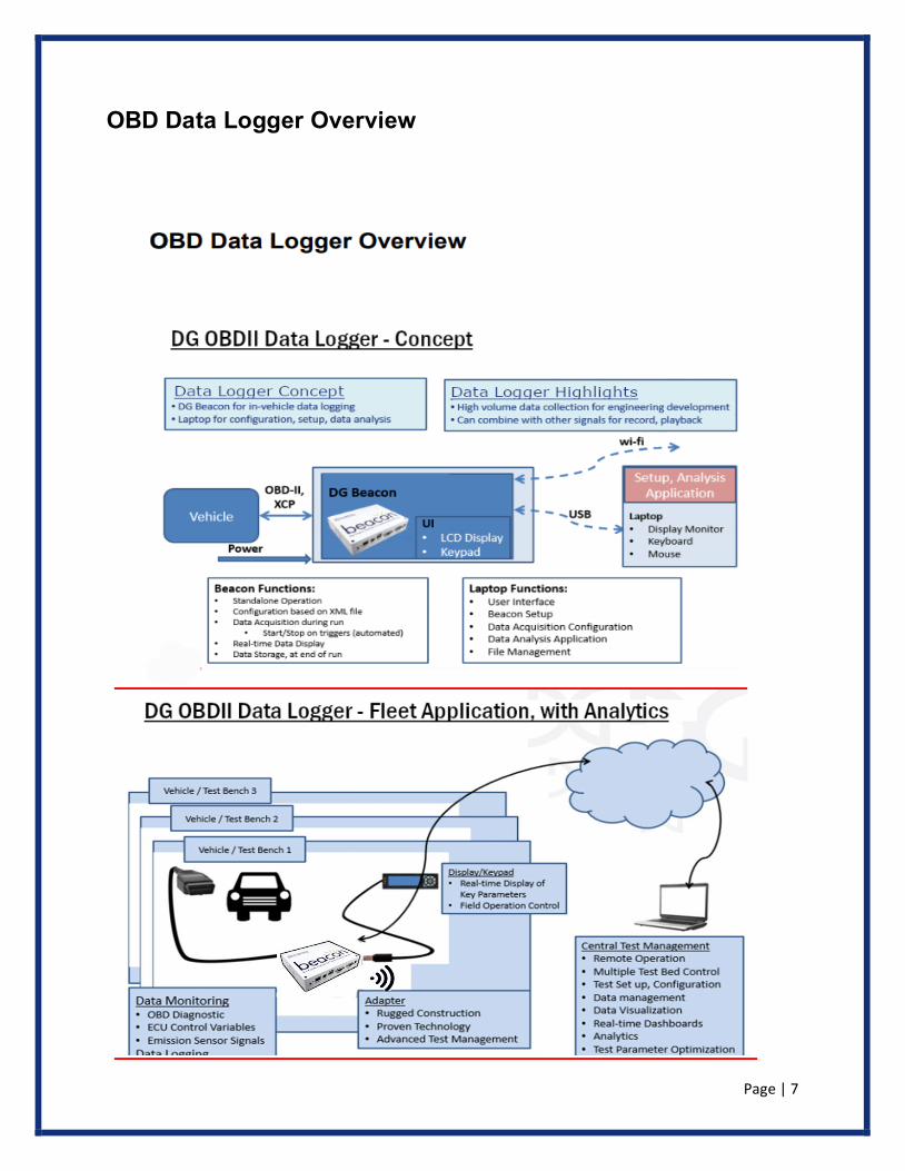
Vehicle Manufacturers and Suppliers: The OBD Data Logger can be used for network system development/validation and troubleshooting, emission testing and validation, fuel efficiency analysis, engineering product development/testing and cybersecurity https://www.dgtech.com/cyber-security/. Features - Based on the DG Beacon network analyzer, the DG OBD Autonomous data logger is an extremely versatile digital data collection system that supports an extensive range of vehicle network and data acquisition needs:
o Data protocols – CAN and CAN-FD o Data interfaces – J2534 and RP1210 o ECU variables as described in A2L file
o The A2L file is defined in DiagRA X program o Seed-Key security mechanism (part of XCP protocol)
o Ability to lock and unlock the module o Automated Cloud data storage to allow access via Internet o Start/Stop on custom data Triggers
Hardware – consists of:
o Processor – ARM Cortex A8, 1 GHz speed o RAM 512 Mbytes SDRAM o NAND Flash Memory – 512 Mbytes o User Storage: Micro SWD card to 64 GBytes o LCD Display and Keypad
Features o Operation utilizing a standard laptop o Easy to use
o Intuitive user interface via portable keypad/display o Data analysis and file management
o Custom functionality available o Suitable of long test runs and fleet data collection
Page | 5
Software – Several items contribute to this area: o Linux OS interface (start/stop process) o On-board Web Server o Embedded DiagRA X
o ECU communication o XCP data
o Gryphon Logger o A2L processing o DBC File compatible o TCP/IP support of standard services into the Beacon (FTP, SSH, etc.) o Module drivers and applications
Logged Data Files
o Are saved in a binary format on the internal SD card and transferrable to thumb drive o Named in a standard format o Can automatically be transferred to internal memory or memory stick
Benefits – There are several contributions for your business by using this system:
o Connects to vehicle via diagnostic connector o Ability to merge OBD Diagnostics and ECU data o Suited for laboratory and vehicle applications o Import/Export data management o Remote control capability for set-up and operation o Report generation o Raw CAN data recorded on all networks o Logged Data File named in a standard format
o Start Logging– Automatic or Manual start and stop o High volume data collection for engineering development o All logged data files can automatically be transferred to:
o Internal memory SD card
o Memory stick o Offloaded wirelessly to a network
o Real Time Data Display o Can combine with other signals for record/playback
o Data Storage, at end of run o Automated Cloud Data Storage allows access via internet o Ability to merge:
o OBD Diagnostics o ECU Data
Page | 6
Use Case – examples: o On-road/Off-road Data Logging o Automated repetitive testing across multiple installations/laboratories o Remote test execution and data collection o Fleet data collection o Fleet application, with analytics o EOL test system o Vehicle emissions testing
Technical Aspects– examples: o ECU communications o GST PID’s o Services and full OBD diagnostic data o XCP measurement parameter data
o ECU variables via XCP Protocol o Automatic or manual start and stop o Start/stop on triggers (automated) o Data file is saved on internal SD card transferrable to a thumb drive o Data is saved in a binary format
Beacon Functions:
o Data Acquisition during run o Start/Stop Triggers (Automated)
o Real Time Data Display
o Data Storage at end of run
Laptop Functions:
o Beacon Setup o Data Acquisition Configuration o Data Analysis Application
o File Management
Page | 7
OBD Data Logger Overview
Page | 8
Standard Usage - Loading Instructions
The Beacon Data Logger is provided with pre-loaded software. No special loading sequence is required.
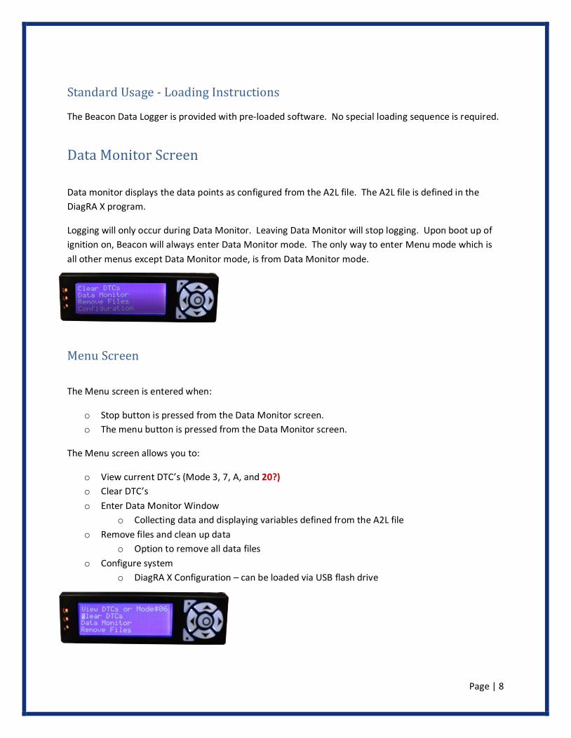
Data Monitor Screen
Data monitor displays the data points as configured from the A2L file. The A2L file is defined in the DiagRA X program.
Logging will only occur during Data Monitor. Leaving Data Monitor will stop logging. Upon boot up of ignition on, Beacon will always enter Data Monitor mode. The only way to enter Menu mode which is all other menus except Data Monitor mode, is from Data Monitor mode.
Menu Screen
The Menu screen is entered when:
o Stop button is pressed from the Data Monitor screen. o The menu button is pressed from the Data Monitor screen.
The Menu screen allows you to:
o View current DTC’s (Mode 3, 7, A, and 20?) o Clear DTC’s o Enter Data Monitor Window
o Collecting data and displaying variables defined from the A2L file o Remove files and clean up data
o Option to remove all data files o Configure system
o DiagRA X Configuration – can be loaded via USB flash drive
Page | 9
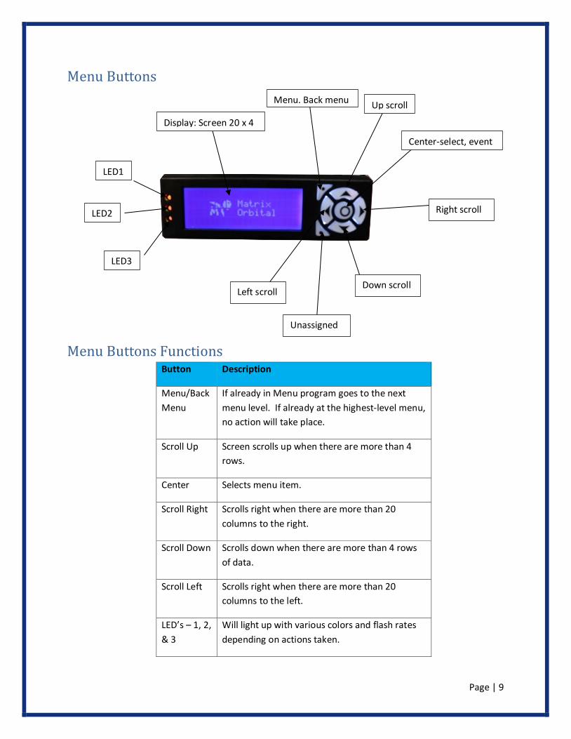
Menu Buttons
Menu Buttons Functions Button Description
Menu/Back Menu
If already in Menu program goes to the next menu level. If already at the highest-level menu, no action will take place.
Scroll Up Screen scrolls up when there are more than 4 rows.
Center Selects menu item.
Scroll Right Scrolls right when there are more than 20 columns to the right.
Scroll Down Scrolls down when there are more than 4 rows of data.
Scroll Left Scrolls right when there are more than 20 columns to the left.
LED’s – 1, 2, & 3
Will light up with various colors and flash rates depending on actions taken.
LED1
LED2
LED3
Display: Screen 20 x 4
Left scroll Down scroll
Right scroll
Center-select, event
Unassigned
Menu, Back menu Up scroll
Page | 10
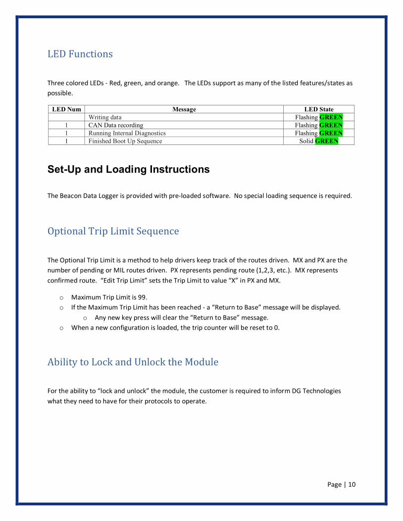
LED Functions
Three colored LEDs - Red, green, and orange. The LEDs support as many of the listed features/states as possible.
LED Num Message LED State Writing data Flashing GREEN 1 CAN Data recording Flashing GREEN 1 Running Internal Diagnostics Flashing GREEN 1 Finished Boot Up Sequence Solid GREEN
Set-Up and Loading Instructions
The Beacon Data Logger is provided with pre-loaded software. No special loading sequence is required.
Optional Trip Limit Sequence
The Optional Trip Limit is a method to help drivers keep track of the routes driven. MX and PX are the number of pending or MIL routes driven. PX represents pending route (1,2,3, etc.). MX represents confirmed route. “Edit Trip Limit” sets the Trip Limit to value “X” in PX and MX.
o Maximum Trip Limit is 99. o If the Maximum Trip Limit has been reached - a “Return to Base” message will be displayed.
o Any new key press will clear the “Return to Base” message. o When a new configuration is loaded, the trip counter will be reset to 0.
Ability to Lock and Unlock the Module
For the ability to “lock and unlock” the module, the customer is required to inform DG Technologies what they need to have for their protocols to operate.
Page | 11
DiagRA X
Embedded DiagRA X is the Beacon data logging mechanism.
DiagRA X is a modern and User-Friendly Measurement and Calibration Tool which simplifies the daily tasks of calibration and measurement engineers working with many labels within their experiments
Features support by PC based DiagRA X:
• Supports XCP on Ethernet, XCP on CAN, CCP and CAN • Integrated ASAP 3 client for connection to test benches and automation systems • Adjustable grid-based layout with pre-configured templates • Optimized setup from program launch to measurement • Day night color schemes, scientific color concept • Customizable gauges, bars, numbers, oscilloscopes etc. • Includes basic analyzer tool DiagRA X Viewer • Clear and simple program configuration • Import and export layouts along with project data • Software functions optimized to maximum user friendliness • Developed in cooperation with calibration engineers • Project, data, and configuration management client with integrated database management system,
file management and search engine • Support for backend systems and third-party products • Based upon ASAM, ISO, and SAE standards
Page | 12
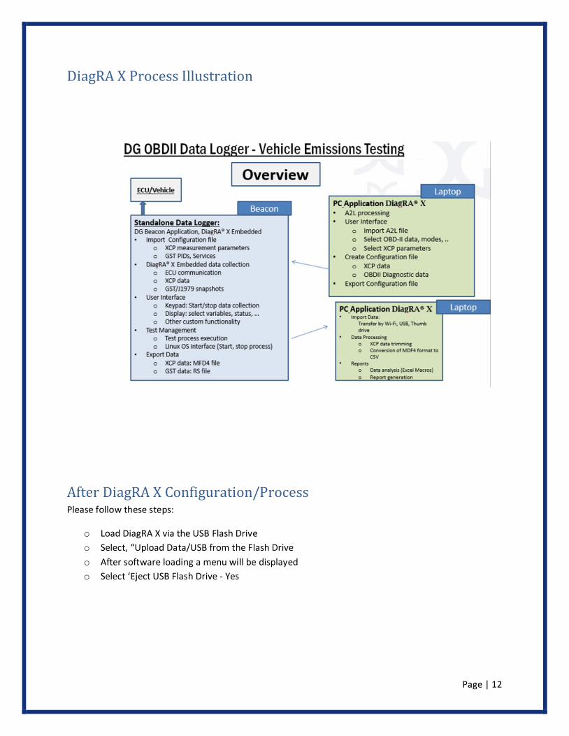
DiagRA X Process Illustration
After DiagRA X Configuration/Process Please follow these steps:
o Load DiagRA X via the USB Flash Drive o Select, “Upload Data/USB from the Flash Drive o After software loading a menu will be displayed o Select ‘Eject USB Flash Drive - Yes
Page | 13
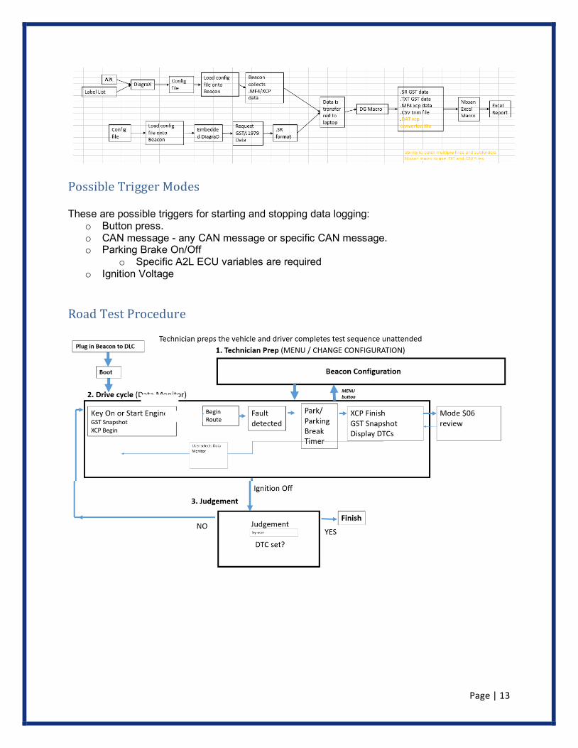
Possible Trigger Modes
These are possible triggers for starting and stopping data logging: o Button press. o CAN message - any CAN message or specific CAN message. o Parking Brake On/Off
o Specific A2L ECU variables are required o Ignition Voltage
Road Test Procedure
Page | 14
Data Monitor
Data Monitor is entered after booting up (hard or soft) or the "Data Monitor" menu selection is chosen. Logging should begin based on the worksheets "Road Test Procedure". All values should not display past the decimal point except for battery voltage.
Page | 15
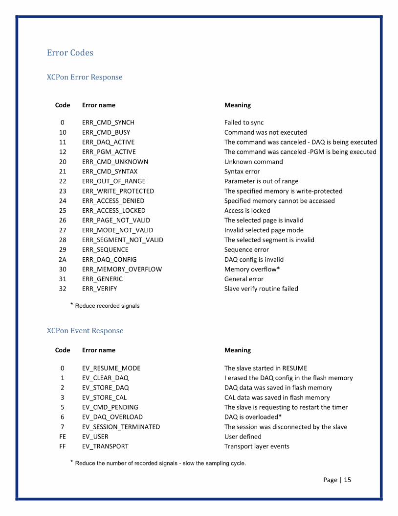
Error Codes XCPon Error Response
Code Error name Meaning
0 ERR_CMD_SYNCH Failed to sync 10 ERR_CMD_BUSY Command was not executed 11 ERR_DAQ_ACTIVE The command was canceled - DAQ is being executed 12 ERR_PGM_ACTIVE The command was canceled -PGM is being executed 20 ERR_CMD_UNKNOWN Unknown command 21 ERR_CMD_SYNTAX Syntax error 22 ERR_OUT_OF_RANGE Parameter is out of range 23 ERR_WRITE_PROTECTED The specified memory is write-protected 24 ERR_ACCESS_DENIED Specified memory cannot be accessed 25 ERR_ACCESS_LOCKED Access is locked 26 ERR_PAGE_NOT_VALID The selected page is invalid 27 ERR_MODE_NOT_VALID Invalid selected page mode 28 ERR_SEGMENT_NOT_VALID The selected segment is invalid 29 ERR_SEQUENCE Sequence error 2A ERR_DAQ_CONFIG DAQ config is invalid 30 ERR_MEMORY_OVERFLOW Memory overflow* 31 ERR_GENERIC General error 32 ERR_VERIFY Slave verify routine failed
* Reduce recorded signals
XCPon Event Response
Code Error name Meaning
0 EV_RESUME_MODE The slave started in RESUME 1 EV_CLEAR_DAQ I erased the DAQ config in the flash memory 2 EV_STORE_DAQ DAQ data was saved in flash memory 3 EV_STORE_CAL CAL data was saved in flash memory 5 EV_CMD_PENDING The slave is requesting to restart the timer 6 EV_DAQ_OVERLOAD DAQ is overloaded* 7 EV_SESSION_TERMINATED The session was disconnected by the slave FE EV_USER User defined FF EV_TRANSPORT Transport layer events
* Reduce the number of recorded signals - slow the sampling cycle.
Page | 16
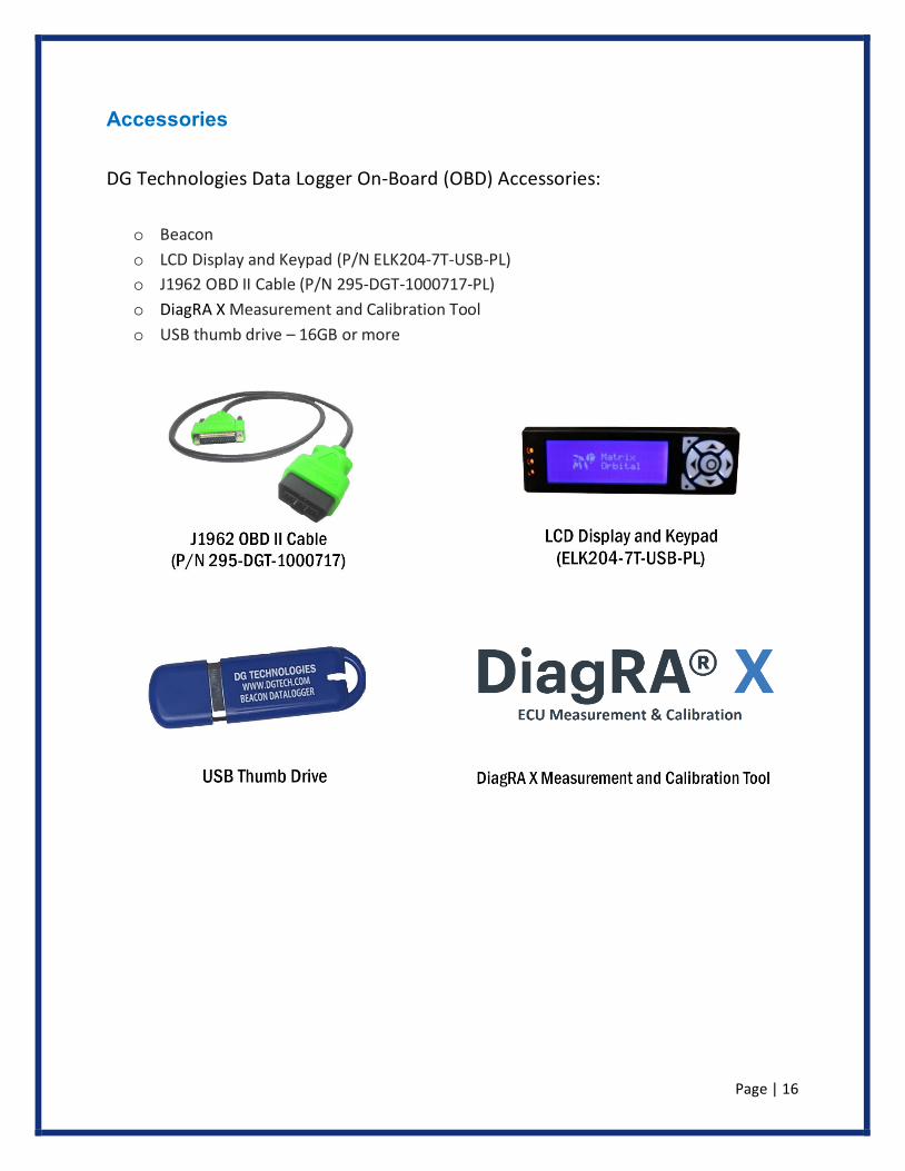
Accessories
DG Technologies Data Logger On-Board (OBD) Accessories:
o Beacon o LCD Display and Keypad (P/N ELK204-7T-USB-PL) o J1962 OBD II Cable (P/N 295-DGT-1000717-PL) o DiagRA X Measurement and Calibration Tool o USB thumb drive – 16GB or more
Page | 17
Technical Support and Return Merchandise Authorization
After reading and following the troubleshooting and validation procedures in this document please check the FAQ page at www.dgtech.com/faqs. If you are still not able to resolve an issue, please feel free to contact DG technical support. For users in the United States, technical support is available from 9 a.m. to 5 p.m. Eastern Time. You may also fax or e-mail your questions to us. For prompt assistance, please include your voice telephone number and the serial number located on the bottom of your OBD Data Logger.
DG Technologies Technical Support
Phone: (248) 888-2000
Fax: (248) 888-9977
E-mail: [email protected]
Web site:www.dgtech.com/tech-support
Users not residing in the United States should contact your local DG representative or e-mail [email protected]
Page | 18
Return Merchandise Authorization (RMA)
If technical support has deemed that there may be a physical problem with your OBD Data Logger, you will be issued you an RMA number. You would then return the product along with any documentation of ownership you have (proof of purchase/price) to the following address:
Product Repair Services
Attn: RMA# xxxxxxx
DG Technologies
33604 West 8 Mile Road
Farmington Hills, MI 48335
Page | 19
Appendix A. Warranty Information and Limitation Statements
Warranty Information DG Technologies, Inc. the OBD Data Logger is warranted against defects in materials and workmanship for two (2) years following date of shipment. Cables (both USB and vehicle) are warranted for 90 days.
DG Technologies will, at its option, repair or replace, at no cost to the customer, products which prove to be defective during the warranty period, provided the defect or failure is not due to misuse, abuse, or alteration of the product. The customer is responsible for shipment of the defective product to DG. This warranty does not cover damage to any item that DG Technologies, determines has been damaged by the customer's abuse, misuse, negligence, improper assembly, modification, or operation of the product.
A Return Merchandise Authorization (RMA) number must be issued to the customer by our Technical Support Department at (248) 888-2000 and must be included with the product being returned (for more details, see section Return Merchandise Authorization (RMA)). The OBD Data Logger is warranted for 90 days after a warranty repair, or to end of the original factory warranty period, whichever is longer.
Limitation Statements
General Limitation and Risk Assignment
To the maximum extent permitted by applicable law, DG Technologies and its suppliers provide support services on an “as-is” basis and disclaim all other warranties and conditions not specifically stated herein, whether express, implied or statutory, including, but not limited to, any warranties of merchantability or fitness for a particular purpose, lack of viruses, accuracy or completeness of responses, results, lack of negligence or lack of workmanlike effort, and correspondence to description. The user assumes the entire risk arising out of the use or performance of the device, its operating system components, and any support services.
Page | 20
Exclusion of Incidental, Consequential and Certain Other Damages
To the maximum extent permitted by applicable law, in no event shall DG Technologies or its suppliers be liable for any special, incidental, indirect or consequential damages whatsoever, including but not limited to: damages for loss of profit, loss of confidential or other information; business interruption; personal injury; loss of privacy, failure to meet any duty (including good faith or of reasonable care); negligence; and any other pecuniary or other loss related to the use of or the inability to use the device, components or support services or the provision of or failure to provide support services or otherwise in connection with any provision, even if DG Technologies or any supplier has been advised of the possibility of such damages.
Limitation of Liability and Remedies
Notwithstanding any damages that you might incur for any reason whatsoever (including, without limitation, all damages referenced above and all direct or general damages), in no event shall the liability of DG Technologies and any of its suppliers exceed the price paid for the device. The user assumes the entire risk and liability from the use of this device.
Right to Revise or Update Without Notice
DG Technologies reserves the right to revise or update its products, software and/or any or all documentation without obligation to notify any individual or entity.
Governance
The user agrees to be governed by the laws of the State of Michigan, USA, and consents to the jurisdiction of the state court of Michigan in all disputes arising out of or relating to the use of this device.
Contact
Please direct all inquiries to:
DG Technologies
33604 West 8 Mile Road
Farmington Hills, MI 48335
Phone (248) 888-2000
Fax (248) 888-9977
Page | 21
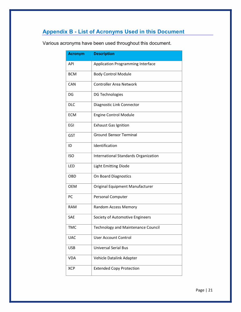
Appendix B - List of Acronyms Used in this Document
Various acronyms have been used throughout this document.
Acronym Description
API Application Programming Interface
BCM Body Control Module
CAN Controller Area Network
DG DG Technologies
DLC Diagnostic Link Connector
ECM Engine Control Module
EGI Exhaust Gas Ignition
GST Ground Sensor Terminal
ID Identification
ISO International Standards Organization
LED Light Emitting Diode
OBD On Board Diagnostics
OEM Original Equipment Manufacturer
PC Personal Computer
RAM Random Access Memory
SAE Society of Automotive Engineers
TMC Technology and Maintenance Council
UAC User Account Control
USB Universal Serial Bus
VDA Vehicle Datalink Adapter
XCP Extended Copy Protection