o r t idiap - pdfs.semanticscholar.org€¦ · order to b e compatible with the reduced frame rate...
TRANSCRIPT

ES
EA
RC
HR
EP
RO
RT
ID
IA
P
D a l l e M o l l e I n s t i t u t efor Perceptua l Art i f i c ia lIntelligence � P.O.Box 592 �Martigny �Valais �Switzerlandphone +41� 27� 721 77 11fax +41� 27� 721 77 12e-mail [email protected] http://www.idiap.ch
IDIAP Martigny - Valais - SuisseSegmentation of X-ray ImageSequences Showing theVocal TractGeorg ThimmIDIAP{RR 99-01
January 1999
IDIAP Research Report 99-01Segmentation of X-ray Image Sequences Showingthe Vocal TractGeorg ThimmJanuary 1999Abstract. The tongue, the lips, the palate, and the throat are tracked in X-ray images showingthe side view of the vocal tract. This is performed by using specialized histogram normalizationtechniques and a new tracking method that is robust against occlusion, noise, and spontaneous,non-linear deformations of objects.Although the segmentation procedure is optimized for the X-ray images of the vocal tract, theunderlying tracking method can easily be used in other applications.Keywords: contour tracking, edge template, joined forward-backward trackingAcknowledgements: This work has been performed with �nancial support from the Swiss NationalScience Foundation under Contract No. 21 49 725 96.

IDIAP{RR 99-01 11 IntroductionAlthough speech and speaker recognition systems archive nowadays high performances in laboratoryconditions, their performance is still unsatisfying under real-life conditions. Several authors havesuggested that more knowledge about the speech production process (e.g co-articulation, dynamics,inter/-intro speaker di�erences) might lead to an improved feature extraction method. Having this inmind, the ARTIST project was proposed to Swiss National Science Foundation. In this project, �rstlyarticulatory features form X-ray movies are extracted (see section 2), and then the speech productionprocess is thoroughly analysed.Tracking is very di�cult in the X-ray database. Our �rst attempt with some variations of point dis-tribution models and grey-level models the surrounding of the points failed [Luettin and Thacker, 1997].One of these variations used the condensation algorithm [Isard and Blake, 1996]. Furthermore, weobserved, that the optical ow �elds obtained for this database are - depending on applied al-gorithm, its parameterization, and the �ltering of the images - almost random or widely unre-lated to the motions of the articulators (we tested the algorithms reported to be best performingin [J.L. Barron and Fleet, 1994]).The approach described in the following is not the �rst that tries to track articulatory features inthis database. In [Laprie and Berger, 1996] and [Berger and Laprie, 1996], the contour of the tongueis tracked in X-ray images, but no �nal results were published and they did not track the lips and thejaws. We are not aware of tracking results published by other authors.For completeness, we want to mention that other researches gain quantitative data on the motionof articulators in various ways:� [Davis et al., 1996] uses MRI and tags (small metal pellets attached to the tongue). The move-ments in 500ms windows for 4 vowels are extracted. But due to technical restrictions, neitherthe movements corresponding to consonants, nor the movements of the throat can be observed.� An alternative approach uses ultra sound [Stone and Davis, 1995] [Stone and Lundberg, 1996].This approach has the disadvantage that lips, tongue, and the lower jaw can not be tracked atthe same time, and that the experiments are di�cult as the head has to be immobilized and thedevice has to be calibrated. However, a high sampling rate (> 1000 frames/second) is possible.2 The X-ray image DatabaseThe ATR X-ray �lm database, which is the largest X-ray database available for speech research[Munhall et al., 1995], was digitized at IDIAP. This database was only in small parts and in a lowquality available in a digitalized form, the original movies are available on a NTSC video-disc. Thedigitized data is stored in Quicktime format including the sound and as separate images in GIF format(approximately 100,000 frames, non-relevant borders are removed). However, for speech analysispurposes, a tape with the original sound should be used as sound on the video disc is modi�ed inorder to be compatible with the reduced frame rate of NTSC.Concerning the articulatory features, the data imposes certain restrictions: the larynx is invisibleon most of the X-ray movies of the ATR database. The features we decided to track are: lips, teeth,palate, tongue, and the upper part of the throat (we did not achieve the tracking of the velum).The tracking of the tongue and the velum are the most challenging problems, as their contours areoften not well de�ned and blurred, or even disappear due to shadowing and contact between them orother organs (i.e. between tongue and palate). The contours obtained for the tongue are thereforesometimes incorrect and/or incomplete.During the digitization and inspection, the characteristics listed in table 1 were observed. Thedigitized database can be obtained form IDIAP.From this database, the �lm Laval 43 with 3944 frames showing the vocal tract was completely ana-lysed and the results are available via the WWWpage of the IDIAP vision group (URL: http:www.idiap.ch/vision).
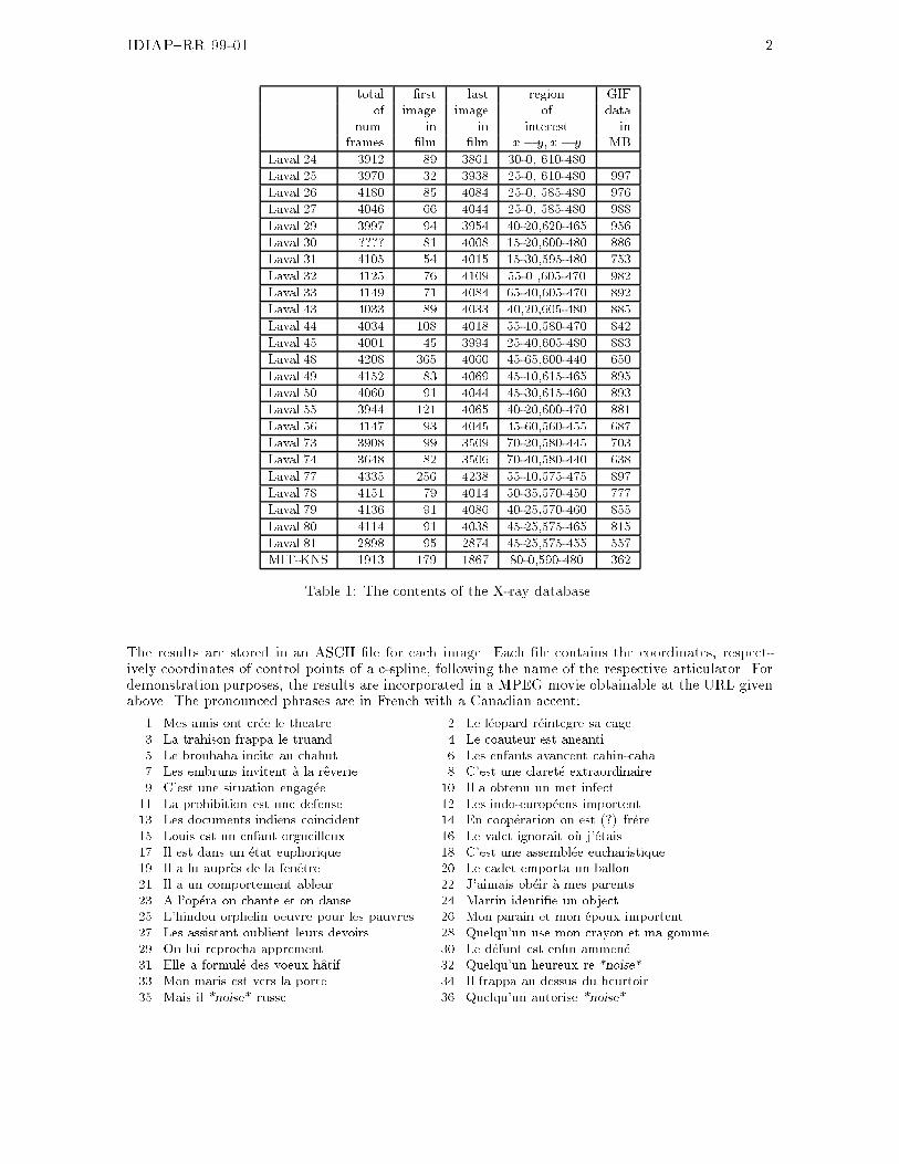
IDIAP{RR 99-01 2total �rst last region GIFof image image of datanum. in in interest inframes �lm �lm x� y; x� y MBLaval.24 3912 89 3861 30-0, 610-480Laval.25 3970 32 3938 25-0, 610-480 997Laval.26 4180 85 4084 25-0, 585-480 976Laval.27 4046 66 4044 25-0, 585-480 988Laval.29 3997 94 3954 40-20,620-465 956Laval.30 ???? 81 4008 15-20,600-480 886Laval.31 4105 54 4015 15-30,595-480 753Laval.32 4125 76 4109 55-0 ,605-470 982Laval.33 4149 71 4084 65-40,605-470 892Laval.43 4033 89 4033 40,20,605-480 885Laval.44 4034 108 4018 55-10,580-470 842Laval.45 4001 45 3994 25-40,605-480 883Laval.48 4208 365 4060 45-65,600-440 650Laval.49 4152 83 4069 45-10,615-465 895Laval.50 4060 91 4044 45-30,615-460 893Laval.55 3944 121 4065 40-20,600-470 881Laval.56 4147 93 4045 45-60,560-455 687Laval.73 3908 99 3509 70-20,580-445 703Laval.74 3648 82 3506 70-40,580-440 638Laval.77 4335 256 4238 55-10,575-475 897Laval.78 4151 79 4014 50-35,570-450 777Laval.79 4136 91 4086 40-25,570-460 855Laval.80 4114 91 4038 45-25,575-465 815Laval.81 2898 95 2874 45-25,575-455 557MIT-KNS 1913 179 1867 80-0,590-480 362Table 1: The contents of the X-ray database.The results are stored in an ASCII �le for each image. Each �le contains the coordinates, respect-ively coordinates of control points of a c-spline, following the name of the respective articulator. Fordemonstration purposes, the results are incorporated in a MPEG movie obtainable at the URL givenabove. The pronounced phrases are in French with a Canadian accent:1. Mes amis ont cr�ee le theatre. 2. Le l�eopard r�eintegre sa cage.3. La trahison frappa le truand. 4. Le coauteur est aneanti.5. Le brouhaha incite au chahut. 6. Les enfants avancent cahin-caha.7. Les embruns invitent �a la reverie. 8. C'est une claret�e extraordinaire.9. C'est une situation engag�ee. 10. Il a obtenu un met infect11. La prohibition est une defense. 12. Les indo-europ�eens importent.13. Les documents indiens coincident. 14. En coop�eration on est (?) fr�ere.15. Louis est un enfant orgueilleux. 16. Le valet ignorait o�u j'�etais.17. Il est dans un �etat euphorique. 18. C'est une assembl�ee eucharistique.19. Il a lu aupr�es de la fenetre. 20. Le cadet emporta un ballon.21. Il a un comportement ableur. 22. J'aimais ob�eir �a mes parents.23. A l'op�era on chante et on danse. 24. Martin identi�e un object.25. L'hindou orphelin oeuvre pour les pauvres. 26. Mon parain et mon �epoux importent.27. Les assistant oublient leurs devoirs. 28. Quelqu'un use mon crayon et ma gomme.29. On lui reprocha apprement. 30. Le d�efunt est en�n ammen�e.31. Elle a formul�e des voeux hatif. 32. Quelqu'un heureux re *noise*33. Mon maris est vers la porte 34. Il frappa au dessus du heurtoir.35. Mais il *noise* russe. 36. Quelqu'un autorise *noise*

IDIAP{RR 99-01 337. S'il a eu un.3 Overview of the SegmentationA sophisticated sequential procedure was developed as traditional methods (edge detection, contourmethods, optical ow, and so on) were found to provide unsatisfactory results.Some articulators are more distinct because of a comparably higher contrast - and consequentlyare easier to �nd in an automated way - than others. Therefore, these are located �rst, and then, usingthe bene�ts of image normalization and constraints on relative positions, more di�cult articulatorsare tracked. In this sense, the following steps are performed, �gure 1 shows a scheme of the procedure:1. The X-ray images are �ltered with a Gaussian �lter and their histograms are then zero-normalized(see section 4.1).2. The upper front teeth are located by the means of a pattern matching algorithm using distortedgrey-level histograms (section 4.2).3. Similarly, a reference point in the rear upper teeth is tracked. Teeth �llings are very robustobjects for this purpose. They have a good contrast and are brighter than any surroundingobjects. Furthermore, the shadow of the tongue does not alter their appearance much. Notethat the position of the upper front teeth and the reference point de�ne also the position of thepalate.4. The position of the head in images is normalized (translation and rotation) using the coordinatesof the upper front teeth and some point of the rear upper teeth.At the same time, the histogram of the images is normalized (i.e. non-linear deformations ofthe histogram are compensated for) using the distortion value obtained for the matching of theupper front teeth.5. and 6. The position of the lower front teeth and a reference point of lower teeth is determined.Again, �llings are very useful.7. Edges are extracted from the normalized images obtained in 4. by the means of a Canny edgedetector.8., 9., and 10. The edges corresponding to the lips and the rear throat are located in the edgeimages extracted in 7. by matching edge templates (see section 5). During the matchingprocedure, the velocity of edges is restricted in order to improve the robustness of the trackingalgorithm against spurious edges and situations where the edges of an articulator are partlyinvisible. However, this causes the algorithm to loose track in the case of fast motions whichoccasionally occur (see the comments in section 7). To counterbalance this de�ciency, thesequences are tracked forward and backward in time and the results of both sequences arejoined together.11. Edges are extracted from the normalized images obtained in 4. by the means of a Canny edgedetector, but negative gradients in the x-direction of the image are set to zero before the edgesare extracted.12. The front throat is tracked in the edge images obtained in step 11. using the same approachas for the lips and the rear throat.13. Image parts representing the upper and lower jaw with the tongue in an advanced and lowered,as well as in a back and high position, are subtracted from the normalized images.14. This gives two series of images, to which a Canny edge detector is applied.

IDIAP{RR 99-01 415. In these images, templates of the edges of the tongue are matched with one of the series ofthe images, depending on the position of the front throat (which is also the location of the reartongue). Furthermore, possible matches are limited by an approach similar to the one used forthe lips and the rear throat.1. Noise filtered images
4. Position and histogram
2. Detection of
5. Detection of lower
6. Detection a reference
11. Edge detectionwith X gradient >0
9. Detection7. Edge detection
8. Detection of
12. Detection
10. Detection
13. Subtraction of images with
14. Edge detection
15. Detection of tongueupper lip of rear thoat
of front throat
of lower lip
point in the lower teeth
front teeth
upper and lower jawnormalized images
point in the upper teethupper front teeth3. Detection a reference
Figure 1: Scheme for the detection of teeth, lips, front and rear throat, as well as the tongue4 Localizing the TeethThe X-ray �lms are a�ected by a variable illumination, caused by either an instable X-ray energy or avarying shutter speed of the camera. This e�ect can not be eliminated by standard linear histogramnormalization. A standard pattern matching algorithm based on a simple distance measure betweengray values is therefore likely to yield unsatisfactory results.4.1 Zero-normalization of the Gray-level HistogramA �rst step to overcome this problem is to remove parts of the histogram: black parts with gray valuessmaller than some value g0 correspond to noise and parts of the image that are of no interest (compare�gures 2(a) and 2(b)). Furthermore, gray-values in the interval [g0; g] are almost not occurring, as

IDIAP{RR 99-01 5shown in �gure 2(d). With respect to these considerations, all pixels with gray values smaller than gare set to g. The modi�ed image is then normalized to again have a gray-level histogram covering thewhole possible range of values. The image 2(c) shows that the modi�ed images have a higher contrast,but yield no other visible artifacts. Although the higher contrast is helpful for the human observer,this is not the main bene�t of the approach, but to obtain the same gray level for the same object inall images.As the cut-o� value g is variable, it is chosen for each image separately according to the formula:g = argmaxK2[g0 ;255]�PKi=g0 hist(i)N < p�: (1)In this formula, hist(i) is the number of pixels with gray value i, N the number of pixels in the image,g0 is chosen close to zero and to the left of the nearly empty part of the gray level histogram, and pthe fraction of pixel values that are allowed in the interval1 [g0; g]. Figure 2(e) shows the histogramof the resulting image.(a) The original image. (b) The points of the his-togram corresponding tothe range [0;47]. (c) The modi�ed image.
g g00.6
0.8
1
1.2
1.4
1.6
0 50 100 150 200 250
0.4
0.2
0 (d) The histogram of the original image 0
0.2
0.4
0.6
0.8
1
1.2
1.4
1.6
0 50 100 150 200 250(e) The modi�ed histogram.Figure 2: The lower part of the histogram of the images can be removed.4.2 Compensating the Non-linear Distortion of the HistogramThe zero-normalization of the histogram is insu�cient, as the histograms are also subject to non-lineardistortions. We compensated for this in the pattern matching process: the histogram of the template ismodi�ed during a comparison with some image location (for more details see [Thimm and Luettin, 1998]).1For the ARTIST project the values g0 = 5 and p = 0:1 appeared to be appropriate, but the results are not sensitiveto the values of these two parameters. In the example given, g0 = 0 would give a very similar result.

IDIAP{RR 99-01 6The function projecting the histogram of the template to the histogram of the image can be regardedas a model of the illumination variation. The illumination changes are represented by a free variablewhich changes the shape of the mapping function. These changes are restricted according to threeassumptions:1. Black and white remain unchanged. Therefore, the lowest and highest intensities in the grey-levelhistogram will be mapped onto themselves.2. Contrasts diminish or augment smoothly when the global illumination changes. Therefore,modi�cations of grey-levels must vary smoothly within neighboring intensity values.3. The relative brightness of arbitrary objects must remain unchanged: if a certain spot in theimage is brighter than another spot, it will remain brighter or, in the limit, assume the sameintensity.5 Tracking Articulators using Edges5.1 The Basic Edge Template Matching ProcedureThis section describes the basic matching procedure for edge templates with an edge image. Theapproach assumes that the object (e.g. the tracked articulatory feature)� is exactly once present in an image,� and it is invariably at the same place and has the same orientation and size, respectively allpossible places, orientations, and sizes of the object are represented in the training data.The procedure is, however, robust against small deformations, translations, and rotations, as well asocclusion and noise. It does not require that the edges corresponding to the object are connected.The matching procedure uses edge images, as produced by a Canny edge detector (compare �g-ure 3(a)). In a �rst step, edges are detected in all normalized images. From these edge images,representative edges that correspond to a certain object are extracted (see �gure 3(b); how to selectrepresentative edges is discussed in section 5.2). Such images are called state images in the follow-ing. These state images are inverted and blurred by a Gaussian �lter, resulting in so-called matchingimages Si (for the ARTIST project, a variance � = 5 pixel for the Gaussian �lter is used, compare�gure 3(c)). Both images are further associated with the same state which is proper to them. Thevariance of the Gaussian �lter is directly related to the tolerance of the matching procedure towardsthe variability of an object.(a) The Canny-�ltered im-age (b) An example for an ex-tracted edge or state image (c) A matching imageFigure 3: Creation of a state (image).

IDIAP{RR 99-01 7The matching images Si (the �gure background is encoded as 0, the foreground as positive values)are used in the matching procedure. The score of a matching images Si with respect to an image Xis calculated as score(Si;X ) =Xx;y X (x; y) � Si(x; y) (2)The matching image Si with i = argmaxk(score(Sk;X )) with respect to some image X is de�nedas the optimal state and written as S(X ).Although equation (2) evokes a rather high computational complexity (per frame n multiplicationsof matrices in the size of the images, if n is the number of possible states), an implementation canbe e�cient: only non-zero parts of the matching image need to be considered in equation (2), whichpermits considerable optimizations. Furthermore, the tracking procedure described in section 5.3limits the number of matching images for which the score has to be calculated to a small subset.A simple tracking procedure would consist of calculating the optimal state for each image and anassociation with the contour of the corresponding optimal state image. As this procedure does notyield satisfactory results, temporal information is used to reduce the number of errors (see section5.3).5.2 Selection of State ImagesIn order to obtain good results with the matching procedure, the edges used for the state imagesshould be selected consistently. In particular, the size of the selected edges and cut-o� points shouldbe similar.As �ve articulatory features are tracked, �ve sets of state images are required. For the ARTISTproject, the following choice for the size and cut-o� points was done by the author (the number inparenthesis is the number of state images for the respective object):Front Throat (83): from the lowest visible point up to the rim of the lower jaw.Tongue (226): from the lowest visible point in the throat (thus including the front throat) forwardsto tip - as far as visible. In some cases, the edge is invisible form the region of the rearrest teethforward or for some intermediate parts.Rear Throat (11): from the lowest visible point up to the place where, in the nasal cavity, the curvehas an inclination of approximatively 60 degrees.Lower Lip (105): from the point where it touches the lower front tooth to the recess point abovethe chin.Upper Lip (75): from the point where it touches the tongue to the recess point below the nose.Example choices are given in �gure 4 by the bold lines. These edge images are generated withoutbackground subtraction, as it is used for the tongue (compare section 6.1).The selection of a representative set of state images can be performed in an iterative manner: �rst,some edge images are selected randomly. Then, the image sequence is tracked using the correspondingset of matching images. If the feature is not well localized in some images, some of the respectiveedges are added to the set of state images and the whole procedure re-iterated.5.3 Adding Temporal Information to the Tracking ProcedureThe basic matching procedure described in section 5.1 can be disturbed by edges not belonging to thetracked object. This tracking procedure can be improved by using temporal information. I.e. underthe assumption that the deformation of a feature between consecutive frames is small, the states that

IDIAP{RR 99-01 8Figure 4: Example choices for selected edges: the bold lines are the selected edges. From the pointsmarked by the ash downwards, the edge of the tongue is also the edge of the front throat.are reachable from a given state is a small subset of the whole training set. For this approach it isnecessary to possess information on which state transitions are possible and which not. Whether ornot a certain transitions is possible, is here estimated by calculating the some distance between statesand then using only a percentage p of the transitions with the smallest distances.Supposed that two edges e1 and e2 are approximated by the cubic splines c1 and c2, respectively.In this notation ci;k is a pair of x- and y-coordinates corresponding to the kth point of spline ci withN points. These points are not the control points of the spline, which are never explicitly used in thefollowing. See [Bartels et al., 1998] for an introduction to splines.Then the distance between two edges is calculated by dividing the surface between the splinesby the mean length of the splines. While calculation the surface between the splines, it has to beconsidered that generally the endpoints of the splines do not necessarily correspond to the same pointsof the feature. Two parts jutting out at the ends (F1 and F2 in �gure 5), each delimited by a part of aspline, the connecting line between the endpoints, and the line between one endpoint and the closestpoint on the opposite spline, have to be neglected. Figure 5 illustrates the situation.c1;1c2;1 c2;i c2;N c1;j`1 `2FF1 F2c1;NF0 = F + F1 + F2Figure 5: Measuring the distance between two splines.The surface F can be calculated by subtracting the surface of the surfaces F1 and F2 from thesurface F0 delimited by the splines and the lines connecting the endpoints (����P ;Q;S���� is the surface

IDIAP{RR 99-01 9of a triangle delimited by the points P;Q; and S):F = F0 � F1 � F2 (3)= N�1Xn=1 �����c1;n; c2;n; c2;n+1����+ ����c1;n; c1;n+1; c2;n+1������ F1 � F2 with (4)F1 = 8>>>>>><>>>>>>:0 if a = c = 1c�1Xn=1����c1;1; c2;n; c2;n+1���� if c 6= 1a�1Xn=1����c1;n; c1;n+1; c2;1���� if a 6= 1F2 = 8>>>>>><>>>>>>:0 if b = d = NN�1Xn=1����c1;N ; c2;n; c2;n+1���� if d 6= NN�1Xn=1����c1;n; c1;n+1; c2;N���� if b 6= Nwhere a; b; c; and d are selected so that1. c1;a is the point on c1 that is closest to c2;1,2. c1;b is the point on c1 that is closest to c2;N ,3. c2;c is the point on c2 that is closest to c1;1, and4. c2;d is the point on c2 that is closest to c1;N .Note, that if a = b or c = d, then F = 0, and that either a or c is equal to one, as well as that eitherb or d is equal to one.The distance Di;j between the splines is then de�ned as the surface F divided by the accumulatedlengths of the parts of the splines c1 and c2 that delimit F :Dn;m = F`1 + `2 with (5)`1 = b�1Xi=a jcn;i � cn;i+1j and`2 = d�1Xi=c jcm;i � cm;i+1jFurthermore, D is augmented by an initial state S0 for which D0;j = 1.To obtain �nally the state transition matrix T , a minimal limit Li, that is proper to each stateSi, is searched, so that for p percent of the transitions Li > Di;j is true. Then, Ti;j is de�ned as 1, ifLi > Di;j and 0 otherwise. For the ARTIST project, typically p = 30% was chosen.5.4 Tracking a FeatureThe tracking procedure is an iterative process, in which the selection of a set of possible states bymeans of the transition matrix T alternates with the calculation of the optimal state with respect to

IDIAP{RR 99-01 10this selection. More precisely, the score of Si with respect to matching image Xt and the optimal state�!S (Xt�1) for the previous frame is calculated using the following formula:��!score(Si;Xt) = (score(Si;Xt) if Tj;i = 1 with �!S (Xt�1) = Sj0 otherwise. (6)Whereas for the �rst image X1 in the sequence, the preceding state is de�ned as S0 (or equivalently:�!S (X0) � S0). Then, the optimal state �!S (Xt) is de�ned as the state with the maximal score.The optimal state sequence �!S is then de�ned as ��!S (X1);�!S (X2); : : :�.6 Joined Forward-Backward TrackingOne important assumption in section 5.3 is, that objects move slowly (i.e. only transitions permittedby the states transition matrix are performed). Although this is true most of the time, there areexceptions: tongue and lips can move so fast that they assume almost extreme positions in consecutiveframes. Section 7 gives some quantitative analysis of maximal velocity and acceleration.However, before and after those high-velocity movements, the velocity and acceleration of therespective articulators is low and ful�lls for a certain time the assumption. The following approachreduces the severity of the assumption on the velocity of the movement according to this observation:1. Calculate the forward tracking sequence �!S as in section 5.3.2. Calculate the backward tracking sequence �S in a similar manner, except for using a score thatrestricts the states in a backward manner: ��score(Si;Xt) = (score(Si;Xt) if Tj;i = 1 with �S (Xt+1) = Sj0 otherwise. (7)3. Join state sequences �!S and �S to form the forward-backward sequence !S (see also �gure 6): !Si = (�!Si if ��!score(�!Si ) � ��score( �Si ) �Si otherwise (8) !S (Xt) = �!S (Xt) Time t !S (Xt) = �S (Xt) ��score(Si;Xt)��!score(Si;Xt) < �!S (Xt) = �S (Xt)�!S (Xt) = �S (Xt) ��!score(Si;Xt) > ��score(Si;Xt)Figure 6: Joined forward-backward tracking: the straight lines represent the correct sequence resultingfrom this approach, the zig-zag lines the wrong parts of the forward, respectively backward, sequence.This approach can be used for the lips as well as for the rear and front throat. The tracking of thetongue is discussed in section 6.1.

IDIAP{RR 99-01 116.1 Tracking the TongueThe tongue causes another problem: it is often hidden by the jaws, which means that the contour ofthe tongue is not or only hardly visible. Sometimes even a human observer is unable detect the preciselocation of the tongue. The tracking procedure is consequently augmented by background subtraction.The background subtraction is, however, a little bit more complex than in standard applications. Asthe upper jaws is not moving, it can be directly be subtracted (�gure 7(a)). However, the backgroundimage with the lower jaw has to be oriented according to the current position of the jaw, which isknown from the tracking of the lower teeth. Furthermore, two background images of the lower jaw withdi�erent tongue positions are required (�gures 7(b) and 7(c)), as the background image necessarilyshows the tongue, and therefore the contour of the tongue will disappear if the tongue in the image isat the same position as in the subtracted background image. Therefore, according to the position ofthe front throat, which can be tracked more easily, one of the two di�erent background images of thelower jaw are used.(a) The upper jaw (b) The lower jaw with thetongue advanced (c) The lower jaw with thetongue drawn backFigure 7: Background images subtracted from images before the edge detection for the tongue.The for this approach required edge images are created in the following way:1. From one normalized image which shows the tongue in a low position, everything but the upperjaw is removed (set to zero; see �gure 7(a)).2. Similarly, from an image where the tongue is in an advanced, lowered position, everything butthe lower jaw is removed (�gure 7(b)), and3. from an image where the tongue is in a retracted, high position, everything but the lower jaw isremoved (�gure 7(c)).4. From each image, the image with upper jaw is subtracted. Then, depending on whether theposition of the rear throat is in an advanced or retracted position, the partial image with thelower jaw and the tongue in the opposite position is also subtracted.5. Finally, the edges in these images are detected.Figure 8 shows an example for this process: from the original in image 8(a) the jaws are subtracted,resulting into the image 8(b). It can be seen that the image region corresponding to tongue is moreuniform and the �llings in the upper teeth disappeared. In consequence, the edge of the tongue in theregion of the mouth is nicely detected by a Canny edge detector (image 8(c)).For the tracking procedure, a set of state is then prepared and the corresponding matching imagesare created as it is described in section 5.1. The tracking procedure is the same, except for using thespecial edge images and selecting possible states also by limiting the distance between the previously

IDIAP{RR 99-01 12(a) A part of a normalizedX-ray image. (b) The image with theupper and lower jaw sub-tracted (the contrast is en-hanced for better visibil-ity). (c) The corresponding edgeimage. The contour of thetongue shows up nicely.Figure 8: An example for the subtraction of the jaws followed by an edge detection as used for thetracking of the tongue.detected front throat and the contour of the tongue in the state image. The distance between all frontthroat state image and tongue state images is calculated in the following way:� If there are horizontal lines, on which both, a point of the tongue edge and the front throat edgeexists, then the maximal Euclidean distance between such points de�nes the distance.� If no such point exist, the highest point of the front throat is extrapolated by a line with aninclination of 2. Then the horizontal distance of the lowest point of the rear part of the tongueto the extrapolating line de�nes the distance.During the match of a state with an edge image, again the assumption of slow motion is used andcounterbalanced by joining forward and backward tracking results. Furthermore, the distance of theposition of the previously detected front throat is used to restrict the matched states for the tongueto typically 30% of all states for the tongue.7 RemarksThe frame rate of 50 images per second is rather low as compared to the maximal velocity observedfor the di�erent articulators. For example for the lower front tooth velocities of 10 to 40 pixel/frame(which corresponds roughly to 17 to 68 cm per second) were encountered. This is high as compared toa maximal observed distance of 76 pixel between arbitrary positions. Furthermore, as the lower jawdoes not move visibly in the frames before and after the event, the movement jumps from zero to veryhigh velocity and acceleration and then rapidly comes to a stop. This causes algorithms like Kalman�lters [Blake et al., 1995] or the condensation algorithm [Isard and Blake, 1996] to loose track, as themotion does not obey the assumption of regular motion (due to the low frame rate).Similarly, for the lower lip and the tongue speeds above 20 pixel per frame (appr. 35 cm persecond) are observable.8 ConclusionWe proposed a contour tracking algorithm that can be applied to objects of which the general positionis known (or limited to a small number of positions), but that are subject to non-linear, spontaneousdeformations. The approach is very robust to noise and occlusion, and is based on the assumptionthat deformations, with the exception of rarely occurring spontaneous deformations, are slow. The

IDIAP{RR 99-01 13approach associates contours with states, and motion, respectively object deformations with statetransitions. During the tracking procedure, the state transitions are restricted to those associated withsmall movements, which are determined by calculating the distance between splines approximatingthe contours. Spontaneous deformations are dealt with by joining the state sequences obtained bytracking the image sequence forward and backward in time.The segmentation of the vocal tract is done in an iterative manner: �rst the teeth were tracked bythe means of two specialized histogram normalization techniques combined with a pattern matchingalgorithm, which also gives the position of the palate. Then by the means of a position normalizationof the vocal tract, the movements of the lips, the tongue, and the throat are restricted to deformations.Based on this, the throat and the lips are tracked. Finally, the con�guration of the front throat isused to restrict the number of deformations of the tongue, and a specialized background subtractiontechnique is used to enhance the contrast of the tongue.We assume that the precision of the tracking procedure is su�cient for speech analysis purposes,although a quantization of the error is infeasible in practice. However, we estimate that the contours ofthe lips, the front, and rear throat are located in more than 98% with a su�cient precision. Similarly,the position of the tongue should be su�ciently precise in 95% of the frames. We further estimatethe error for the position of the teeth below 7 pixel (approximatively 2mm).With respect to the obtained results, the low quality of the X-ray database, and the di�cultiesproper to this type of data, the method can be estimated to be very robust.References[Bartels et al., 1998] Richard H. Bartels, John C. Beatty, and Brian A. Barsky. An Introduction toSplines for use in Computer Graphics and Geometric Modeling. Morgan Kaufmann Publishers Inc.,September 1998.[Berger and Laprie, 1996] M.-O. Berger and Y. Laprie. Tracking articulators in X-ray images withminimal user interaction: Example of the tongue extraction. In Proceedings of IEEE InternationalConference on Image Processing, Lausanne, Switzerland, volume II, page 289�, September 1996.[Blake et al., 1995] Andrew Blake, Michael Isard, and David Reynard. Learning to track the visualmotion of contours. Arti�cial Intelligence, 78:101{133, 1995.[Davis et al., 1996] Edward P. Davis, Andrew S. Douglas, and Maureen Stone. A continuum mech-anics representation of tongue deformation. In H. Timothy Bunnell and William Idsardi, editors,Proceedings ICSLP96: Fourth Conference on Spoken Language Processing, volume 2, pages 788{792,New Castle, Delaware, 1996. Citation Delaware.[Isard and Blake, 1996] Michael Isard and Andrew Blake. Contour tracking by stochastic propagationof conditional density. In ECCV'96, 1996.[J.L. Barron and Fleet, 1994] S.S. Beauchemin J.L. Barron and D.J. Fleet. On optical ow. In Int.Conf. on Arti�cial Intelligence and Information-Control Systems of Robots, pages 3{14, Bratislava,Slovakia, September 12-16, 1994.[Laprie and Berger, 1996] Y. Laprie and M.O. Berger. Towards automatic extraction of tongue con-tours in x-ray images. In Proceedings of International Conference on Spoken Language Processing96, volume 1, pages 268{271, Philadelphia (USA), October 1996.[Luettin and Thacker, 1997] Juergen Luettin and Neil A. Thacker. Speechreading using probabilisticmodels. Computer Vision and Image Understanding, 65(2):163{178, 1997.[Munhall et al., 1995] K.G. Munhall, E. Vatikiotis-Bateson, and Y. Tokhura. X-ray �lm database forspeech research. Journal of the Acoustical Society of America, 98(2):1222{1224, 1995.

IDIAP{RR 99-01 14[Stone and Davis, 1995] M. Stone and E.P. Davis. A head and transducer support system for makingultrasound images of tongue/jaw movement. J. Acoust. Soc. Am., 98(6):3107{3112, 1995.[Stone and Lundberg, 1996] M. Stone and L. Lundberg. Three-dimensional tongue surface shapes ofenglish consonants and vowels. J. Acoust. Soc. Am., 99(6):1{10, 1996.[Thimm and Luettin, 1998] Georg Thimm and Juergen Luettin. Illumination-robust pattern match-ing using distorted color histograms. IDIAP-RR 9, IDIAP, Rue de Simplon 4, CP 592, CH-1920Martigny, Switzerland. Email: [email protected], June 1998.