o p e ns p r i nk l e r pi ( o s pi ) v 1 . 4 3 + u s e r ... · o p e ns p r i nk l e r pi ( o s...
TRANSCRIPT
OpenSprinkler Pi (OSPi) v1.43+ User Manual (Updated Oct 8, 2017)
Contents Introduction
Hardware Interface
Hardware Setup
0. Preparation
1. Test Power Supply
2. Attach RPi to OSPi
3. Web Connectivity
5. Zone Expansion Board
6. Rain Sensor / Flow Sensor / Program Switch
7. Analog-Digital Converter (Advanced Topic)
8. Radio Frequency (RF) Transmitter (Advanced Topic)
Software Setup
1. Install OpenSprinkler Unified Firmware
2. Using OSPi Firmware
Technical Details
RPi Pin Uses
Specifications
Terms and Conditions
Open-Source Links
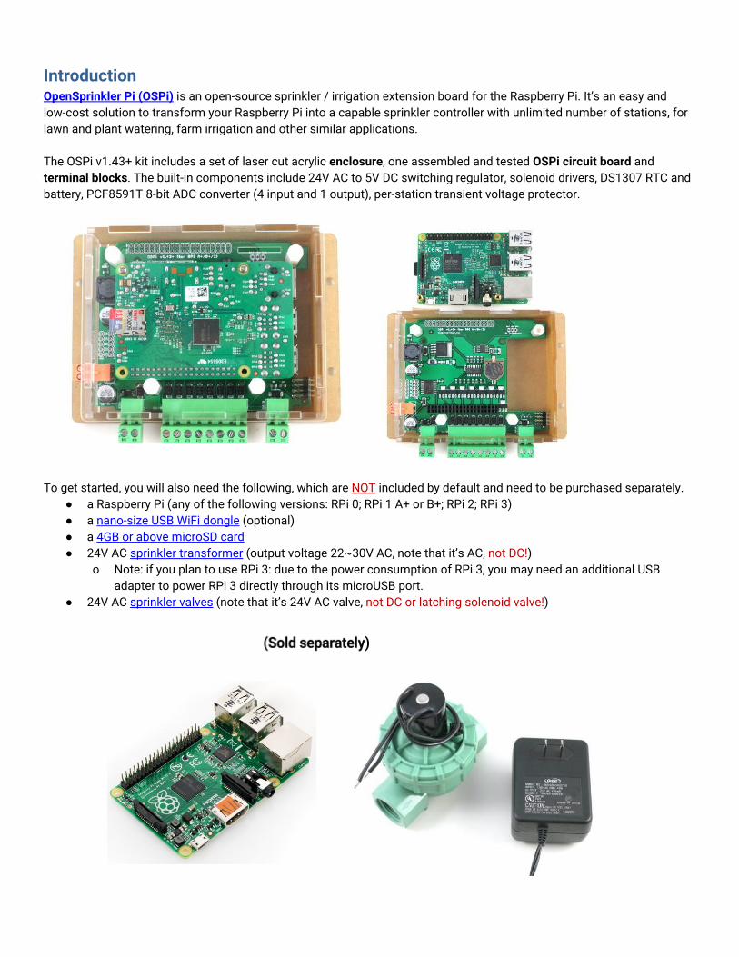
Introduction OpenSprinkler Pi (OSPi) is an open-source sprinkler / irrigation extension board for the Raspberry Pi. It’s an easy and low-cost solution to transform your Raspberry Pi into a capable sprinkler controller with unlimited number of stations, for lawn and plant watering, farm irrigation and other similar applications. The OSPi v1.43+ kit includes a set of laser cut acrylic enclosure, one assembled and tested OSPi circuit board and terminal blocks. The built-in components include 24V AC to 5V DC switching regulator, solenoid drivers, DS1307 RTC and battery, PCF8591T 8-bit ADC converter (4 input and 1 output), per-station transient voltage protector.
To get started, you will also need the following, which are NOT included by default and need to be purchased separately. ● a Raspberry Pi (any of the following versions: RPi 0; RPi 1 A+ or B+; RPi 2; RPi 3) ● a nano-size USB WiFi dongle (optional) ● a 4GB or above microSD card ● 24V AC sprinkler transformer (output voltage 22~30V AC, note that it’s AC, not DC!)
o Note: if you plan to use RPi 3: due to the power consumption of RPi 3, you may need an additional USB adapter to power RPi 3 directly through its microUSB port.
● 24V AC sprinkler valves (note that it’s 24V AC valve, not DC or latching solenoid valve!)

Hardware Interface The left image below marks the connectors and locations of various pinouts. The right image marks the locations of the USB WiFi dongle and SD card after the Raspberry Pi is plugged in.
Hardware Setup 0. Preparation OSPi 1.43+ comes with a laser-cut acrylic enclosure. Enclosure assembly instructions can be found in this Youtube Video. You can do so either before or after the following setup steps. ● If the RTC battery (CR1220) is not pre-installed, insert the battery to the brown battery jack, with positive
(marked by +) facing up. ● If terminal blocks are pre-installed, you need to first remove all terminal blocks before assembling the
acrylic enclosure.
1. Test Power Supply Insert the sprinkler transformer wires into the orange terminal, then plug it into the matching terminal on OSPi. The green LED should light up, indicating power is on. See pictures below.
Warning: if the LED doesn’t light up, please unplug the power immediately. If you can’t figure out the problem, send an email to [email protected].
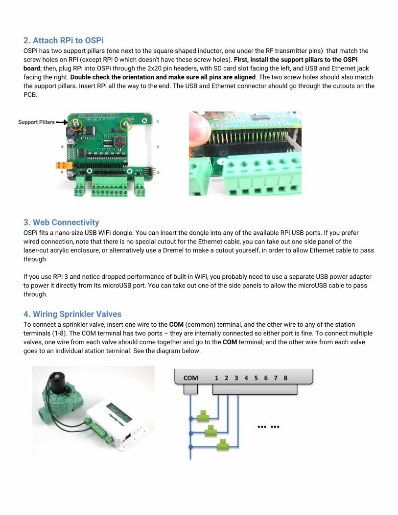
2. Attach RPi to OSPi OSPi has two support pillars (one next to the square-shaped inductor, one under the RF transmitter pins) that match the screw holes on RPi (except RPi 0 which doesn't have these screw holes). First, install the support pillars to the OSPi board; then, plug RPi into OSPi through the 2x20 pin headers, with SD card slot facing the left, and USB and Ethernet jack facing the right. Double check the orientation and make sure all pins are aligned. The two screw holes should also match the support pillars. Insert RPi all the way to the end. The USB and Ethernet connector should go through the cutouts on the PCB.
3. Web Connectivity OSPi fits a nano-size USB WiFi dongle. You can insert the dongle into any of the available RPi USB ports. If you prefer wired connection, note that there is no special cutout for the Ethernet cable, you can take out one side panel of the laser-cut acrylic enclosure, or alternatively use a Dremel to make a cutout yourself, in order to allow Ethernet cable to pass through. If you use RPi 3 and notice dropped performance of built-in WiFi, you probably need to use a separate USB power adapter to power it directly from its microUSB port. You can take out one of the side panels to allow the microUSB cable to pass through.
4. Wiring Sprinkler Valves To connect a sprinkler valve, insert one wire to the COM (common) terminal, and the other wire to any of the station terminals (1-8). The COM terminal has two ports – they are internally connected so either port is fine. To connect multiple valves, one wire from each valve should come together and go to the COM terminal; and the other wire from each valve goes to an individual station terminal. See the diagram below.

5. Zone Expansion Board To connect a zone expansion board, use the extension cable you received to link the OSPi’s OUT port to the expansion board’s IN port. The connector on the cable is polarized (with a bump on the top), so there is only one way to plug it. If you have multiple expansion boards, you can daisy chain them in the same way, by following the OUT -> IN links. When using zone expansion boards, the sprinkler valves are wired the same way as before: one wire from each valve should come together and go to the COM terminal on the OSPi; and the other wire from each valve goes to an individual station terminal.
6. Rain Sensor / Flow Sensor / Program Switch If you have a rain sensor, you can connect it to OSPi via the rain sensor terminal. The rain sensor has two wires and is essentially a rain-activated switch. The OSPi software can decide what to do when rain is detected, such as turn off stations or ignore rain. The latest OpenSprinkler also supports using the sensor terminal to connect a flow sensor, or program switch. Please refer to the OpenSprinkler User Manual Sensors Section for details.
7. Analog-Digital Converter (Advanced Topic) OSPi has a built-in PCF8591T A/D D/A converter, which provides four 8-bit analog inputs, and one analog output. The analog inputs can be used to read analog sensors, such as light, temperature, soil humidity. Details on how to use this converter can be found in this blog post.
8. Radio Frequency (RF) Transmitter (Advanced Topic) The current OSPi has a 3-pin header that fits a 433MHz or 315MHz radio frequency (RF) transmitter. This allows you to use OSPi to communicate with RF wireless power sockets. Please refer to the OpenSprinkler User Manual RF Transmitter Section for details.
Software Setup
1. Install OpenSprinkler Unified Firmware The recommended way to install OpenSprinkler Firmware is to start from a standard Raspbian image, make sure you can boot RPi correctly, then follow the OSPi firmware installation instructions below to install the firmware yourself:
● OSPi Firmware Installation Instructions
NOTE: some Raspbian systems installed by NOOBs will take over GPIO 4 for 1-wire interface, but that OSPi needs GPIO 4 to send control signals to the solenoid valves. If you found that the firmware runs correctly but OSPi does not turn on valves correctly, one solution is to sudo open /etc/modules, and comment out the line containing w1-gpio, then reboot. Another solution is to reinstall Raspbian OS from scratch without using NOOBs.
The previous OSPi pre-configured SD card image is retired -- we no longer provide pre-configured SD card image because it's relatively easy to install a fresh Raspbian and follow the instructions above to install the OpenSprinkler firmware.
2. Using OSPi Firmware The default firmware set to run on start-up is the OpenSprinkler Unified Firmware. It’s available at port 8080. Open a browser, and type in http://ospi_ip:8080/ to start using the firmware, where ospi_ip is your OSPi's local IP address. Details about the OpenSprinkler Unified Firmware can be found in the OpenSprinkler Firmware User Manual:
● OpenSprinkler User Manual
The two alternative firmwares are the Python Interval Program (written by Dan Kimberling) and the sprinklers_pi program (written by Rich Zimmerman). Please refer to their specific Github repositories for installation and usage instructions.
If you want to write your own firmware, use the provided firmwares as starting point. In addition, in the OSPi Github folder, there are a few demo programs that shows basic solenoid control in various programming languages.
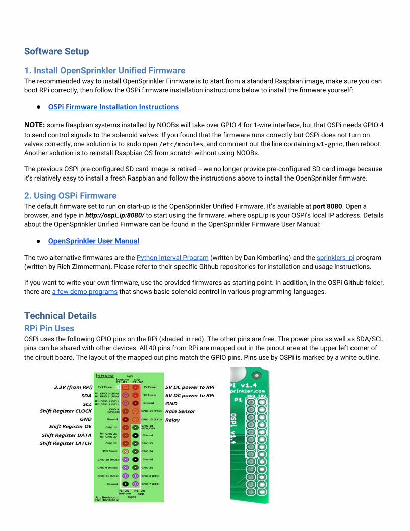
Technical Details RPi Pin Uses OSPi uses the following GPIO pins on the RPi (shaded in red). The other pins are free. The power pins as well as SDA/SCL pins can be shared with other devices. All 40 pins from RPi are mapped out in the pinout area at the upper left corner of the circuit board. The layout of the mapped out pins match the GPIO pins. Pins use by OSPi is marked by a white outline.

Specifications ● Input Voltage: 22V AC to 30V AC. ● DC Output Current: 500mA @ 5V (to power RPi). ● Number of Zones: 8 on the OSPi, expandable by linking zone expansion boards. ● AC Output Current: 800mA continues @ 24V AC per zone / station, 8A impulse / inrush. ● Over-voltage Protection: 48V bi-directional TVS on each zone, AC input, and rain sensor terminal. ● Over-current Protection: 2A on AC input; 1A on 5V DC. ● Size: 135mm x 100mm x 32mm (5.3” x 4” x 1.26”) ● Weight: 150g (5.3oz) w/o RPi
Terms and Conditions OpenSprinkler Pi (OSPi) is an open-source project. The hardware design and software code are made publicly available under the Creative Commons Attribution-ShareAlike (CC BY--SA) 3.0 license. The product is open-source for educational purpose and to promote innovations. The hardware and software are provided as is. We (Rayshobby LLC) are not responsible for any damage or accident that may occur due to hardware or software error, or during the assembly, use, and modification of OSPi.
Open-Source Links ● OSPi Github Repository
● OpenSprinkler Firmware Github Repository
● OSPi homepage