nyc department of environmental protection … department of environmental protection . bureau of...
TRANSCRIPT

NYC Department of Environmental Protection Bureau of Engineering Design and Construction
Cost Estimating Manual Issued June 2008


i
Table of Contents
Cost Estimating Manual - Issued June 2008Table of Contents
Chapter 1 – IntroductionIntroduction ................................................................................................................................... 1-1 Estimating Framework .................................................................................................................. 1-2Manual Organization ..................................................................................................................... 1-4Compliance with Cost Estimating Manual .................................................................................... 1-4
Chapter 2 – Inputs to Estimating ProcessIntroduction ................................................................................................................................... 2-1 Estimate Preparation Services ...................................................................................................... 2-1Estimate Work Breakdown Structure (WBS) ................................................................................ 2-2Project Scope ................................................................................................................................ 2-7Project Risks ............................................................................................................................... 2-10Project Schedule ......................................................................................................................... 2-11Pre-Estimate Meeting .................................................................................................................. 2-11
Chapter 3 – Estimate PreparationEstimating System Requirements ................................................................................................ 3-1 Estimating Methodology ............................................................................................................... 3-2Estimate Structure and Definitions ............................................................................................... 3-4Estimating System Rates and Supporting Calculations ............................................................ 3-10Estimate Inputs ........................................................................................................................... 3-12Escalation of Construction Cost Inputs ...................................................................................... 3-13Estimate Sections ....................................................................................................................... 3-14
Chapter 4 – Estimate OutputBasic Estimate Reports ................................................................................................................. 4-1 Basis of Estimate Report ............................................................................................................... 4-3
Chapter 5 – ContingencyIntroduction ................................................................................................................................... 5-1 Contingency Definitions ................................................................................................................ 5-2Key Source of Risk and Variability ................................................................................................ 5-3Methods for Setting Contingency ................................................................................................. 5-8
Chapter 6 – Estimate Review and ApprovalIntroduction ................................................................................................................................... 6-1 Cost Estimating Team Review ...................................................................................................... 6-1Project Management and Design Team Review ........................................................................... 6-3Design Consultant Senior Management Endorsement ............................................................... 6-5

ii
Cost Estimating Manual June 2008
Cost Estimating Manual - Issued June 2008Table of Contents
List of AttachmentsAttachment 1-1 AACE 18R-97
Attachment 2-1 BEDC Work Packages by CSI Division
Attachment 2-2 Design Content by Estimate Class
Attachment 3-1 Sample Wage Rate Calculation
Attachment 3-2 Sample Work Week Differential Calculations
Attachment 3-3 Estimator Inputs
3-3A Equipment
3-3B Earthwork
3-3C Structural Concrete
3-3D Electrical
3-3E Process Piping
3-3F Indirect Project Cost
Attachment 3-4 Indirect Project Costs Checklist
Attachment 4-1 Estimating Reports
4-1A WBS Level 1 Summary Report
4-1B WBS Level 2 Summary Report
4-1C Scope Review Report Summarized to Assembly
4-1D Scope Review Report Detailed
4-1E Labor Productivity Detail Report (Assembly)
4-1F Labor Productivity Detail Report (Item)
Attachment 4-2 AACE 34R-05
Attachment 5-1 Guidance on Contingency Levels for Primary Construction Inputs

Chapter 1
Introduction
Chapter 1
Introduction


1-1
Chapter 1 Introduction
Chapter 1 – Introduction
Introduction
Accurate cost estimating is essential for the effective management of the New York City, Department of
Environmental Protection’s Capital Program. To ensure consistency across all projects and to facilitate
review and approval of all cost estimates prepared for the Capital Program, the Bureau of Engineering
Design and Construction (BEDC) has developed this Cost Estimating Manual. Key objectives of Manual
include the following:
• Standardizationinengineeringinputs(scope)atallestimatingmilestonestodriveconsistencyintheexpected accuracy range of cost estimates
• Standardizationofestimatingformattofacilitatedevelopment,review,andhistoricaldatacapture
• Guidance on development of appropriate contingency levels to facilitate better transparency anddecision-making in Capital Program budgeting
• Standardizationinthesubmittalofestimatesupportingdocumentationincludingsourcesofinformationand assumptions used to develop the estimate
• MinimumqualityrequirementsforestimatereviewpriortosubmittaltoBEDC
TheManualidentifiesrequirementsoftheentireestimatingprocesscoveringthefollowingeightmajorsteps
in cost estimating:
E i g h t M a j o r
S t E p S i n C o S t
E S t i M a t i n g
1Communicate Project Scope to Estimating Team
(ScopeInputfromEngineertoEstimator)
2Plan the Estimate Preparation
(WorkBreakdownStructureandEstimateStructure)
3Develop Estimate
4Risk Analysis and Contingency Development
5Output Estimate
6Document Basis of Estimate
7Quality Review
(Estimating Team and Engineering Team)
8Submit Estimate to BEDC

1-2
Cost Estimating Manual June 2008
Estimating Framework
The estimating framework described in this Manual is largely based on the Association for the Advance-
ment of Cost Engineering (AACE) Recommended Practice No. 18R-97: Cost Estimate Classification Sys-
tem – As Applied in Engineering, Procurement and Construction for the Process Industries. This AACE
Recommended Practice has been adapted and expanded to the specific needs and characteristics of the
BEDC Capital Program. A copy of this Practice can be obtained from the AACE website at www.aacei.org/
technical/rp.shtml and is included as Attachment 1-1 to this Manual.
AACEPractice18R-97utilizesafivelevelClassSystem(5,4,3,2,and1)whichcorrespondstoestimate
typespreparedatvariousstagesofprojectdevelopment.Type5costestimatesaredevelopedaproject
conception when little project information or scope has been developed. Type 1 estimates are complete
detailed unit cost and take off estimates with complete or near complete scope definition. For planning and
budgetingpurposes,BEDCrequiresdevelopmentofprojectcostestimatesatthevariousmilestoneswithin
the project life cycle. The correlation between the estimates produced at each of the key BEDC project
life cycle milestones and AACE estimate classes is shown in Figure 1.1. For each delivery milestone, the
generally accepted estimating methods, expected level of accuracy, level of scope definition, and the key
scopecontentrequirementsnecessarytodeveloptheestimateareidentified.

1-3
Chapter 1 Introduction
Fig
ur
E 1
-1
Su
MM
ar
y o
F C
oS
t E
St
iMa
tE
Cl
aS
SiF
iCa
tio
nS
ap
pl
iEd
to
ny
C d
Ep
Bu
rE
au
oF
En
gin
EE
rin
g d
ES
ign
an
d C
on
St
ru
Ct
ion
Ca
pit
al
pr
oj
EC
tS
Esti
mat
E Cha
raCt
Eris
tiCs
AACE
Est
imat
e Cl
ass
Clas
s 5
Clas
s 4
Clas
s 3
Clas
s 2
Clas
s 1*
Estim
ate
Met
hodo
logy
Para
met
ric o
r Ca
paci
ty F
acto
red
Equi
pmen
t Fac
tore
d
or P
aram
etric
Sem
i-Det
aile
d Un
it Co
sts
with
Ass
embl
y Le
vel L
ine
Item
s
Deta
iled
Unit
Cost
w
ith F
orce
d De
taile
d Ta
ke-o
ff
Deta
iled
Unit
Cost
w
ith D
etai
led
Take
-off
Expe
cted
Lev
el o
f Acc
urac
y-5
0% to
+10
0%-3
0% to
+50
%-2
0% to
+30
%-1
5% to
+20
%-1
0% to
+15
%
Key
Cont
ent R
equi
rem
ents
(Sco
pe C
onte
nt
Exam
ples
)
0 to
2%
Hydr
aulic
Cap
acity
1 to
15%
Proc
ess
Flow
Dia
gram
Desi
gn C
riter
ia
Gene
ral S
ite L
ayou
t
Pipe
line
Corr
idor
s
Prel
im. E
quip
men
t Li
sts
Prel
im. E
lect
rical
Loa
ds
10 to
40%
Fina
l Equ
ipm
ent L
ists
Site
Lay
out (
Earth
wor
k)
Build
ing/
Faci
lity
Plan
s
Maj
or S
ectio
ns
Conc
rete
Qua
ntiti
es
Fina
l P&I
Ds
Elec
trica
l Sin
gle
Line
s
40 to
70%
Prel
imin
ary
to
Adva
nced
Dra
win
gs
Maj
or S
peci
ficat
ions
95 to
100
%
Com
plet
e An
nota
ted
Draw
ings
Com
plet
e
Spec
ifica
tions
* Pe
r AA
CE
18R
-97,
Cla
ss 1
est
imat
es a
re g
ener
ally
pre
pare
d on
ly fo
r dis
cret
e pa
rts o
r sec
tions
of t
he to
tal p
roje
ct w
hen
prep
arin
g ow
ner’s
est
imat
es,
or p
repa
red
by su
bcon
tract
ors f
or b
iddi
ng p
urpo
ses.
Acc
ordi
ngly
, whi
le se
ctio
ns o
f an
estim
ate
used
by
DEP
mig
ht b
e pr
epar
ed to
Cla
ss 1
stan
dard
s, th
e ov
eral
l est
imat
e is
onl
y
cons
ider
ed a
Cla
ss 2
est
imat
e.
Faci
lity
Plan
ning
Faci
lity
Plan
ning
Initi
atio
n90
/100
%
Mile
ston
eLi
fe C
ycle
Pha
se30
%
Mile
ston
eDe
sign
: 60
% M
ilest
one

1-4
Cost Estimating Manual June 2008
Manual Organization
ThisManualdescribesstandardizedproceduresusedinthedevelopmentofCapitalProjectcostestimates
insupportofdeliveryofBEDC’sCapitalProgram.TheManualisorganizedintothefollowingChaptersand
associated main subject areas:
Chapter 2 – inputs to the Estimating process• EstimatePreparationServices
• EstablishWorkBreakdownStructure(WBS)
• ProjectScope
• ProjectRisks
• ProjectSchedule
• Pre-EstimatePreparationMeeting
Chapter 3 – Estimate preparation• EstimatingSystemRequirements(Software)
• EstimatingMethodology
• EstimateStructureandDefinitions
• EstimatingSystemRatesandSupportingCalculations
• EstimateInputs
• EscalationofConstructionInputs
• EstimateSections
Chapter 4 – Estimate output• BasicEstimateReports
• BasisofEstimateReport
Chapter 5 – Contingency• ContingencyDefinitions
• KeySourcesofRiskandVariability
• MethodsforAnalyzingRiskandSettingContingency
Chapter 6 – Estimate review and approval• CostEstimatingTeamReview
• ProjectTeamReview
• ConsultantSeniorManagementReviewAndEndorsement
Compliance with Cost Estimating Manual
AllcostestimatespreparedforBEDCduringfacilityplanninganddesigneffortsshalladheretotherequire-
ments of this Manual. Exception to compliance with this Manual must be received in writing from the Con-
sultant Project Manager and submitted to the BEDC Project Manager at the initiation of design. Waivers will
bereviewedonacasebycasebasisweighingprojectsize,complexity,andreasonsforvariancerequest.

Chapter 1
Attachments


1
Attachment 1-1 AACE 18R-97
Attachment 1-1 AACE 18R-97
Copyright 2000 AACE, Inc. AACE International Recommended Practices and Standards
AACE International Recommended Practice No. 18R-97
COST ESTIMATE CLASSIFICATION SYSTEM – AS APPLIED INENGINEERING, PROCUREMENT, AND CONSTRUCTION FOR
THE PROCESS INDUSTRIES

2
Attachment 1-1 AACE 18R-97
Copyright 2000 AACE, Inc. AACE International Recommended Practices and Standards
Recommended Practice No. 18R-97Cost Estimate Classification System – As Applied in Engineering,Procurement, and Construction for the Process Industries
June 15, 1998
PURPOSE
As a recommended practice of AACE International, the Cost Estimate Classification System providesguidelines for applying the general principles of estimate classification to project cost estimates (i.e., costestimates that are used to evaluate, approve, and/or fund projects). The Cost Estimate ClassificationSystem maps the phases and stages of project cost estimating together with a generic maturity andquality matrix, which can be applied across a wide variety of industries.
This addendum to the generic recommended practice provides guidelines for applying the principlesof estimate classification specifically to project estimates for engineering, procurement, and construction(EPC) work for the process industries. This addendum supplements the generic recommended practice(17R-97) by providing:
• a section that further defines classification concepts as they apply to the process industries;• charts that compare existing estimate classification practices in the process industry; and• a chart that maps the extent and maturity of estimate input information (project definition deliverables)
against the class of estimate.
As with the generic standard, an intent of this addendum is to improve communications among all ofthe stakeholders involved with preparing, evaluating, and using project cost estimates specifically for theprocess industries.
It is understood that each enterprise may have its own project and estimating processes andterminology, and may classify estimates in particular ways. This guideline provides a generic andgenerally acceptable classification system for process industries that can be used as a basis to compareagainst. It is hoped that this addendum will allow each user to better assess, define, and communicatetheir own processes and standards in the light of generally-accepted cost engineering practice.
INTRODUCTION
For the purposes of this addendum, the term process industries is assumed to include firms involvedwith the manufacturing and production of chemicals, petrochemicals, and hydrocarbonprocessing. The common thread among these industries (for the purpose of estimate classification) istheir reliance on process flow diagrams (PFDs) and piping and instrument diagrams (P&IDs) as primaryscope defining documents. These documents are key deliverables in determining the level of projectdefinition, and thus the extent and maturity of estimate inputinformation.
Estimates for process facilities center on mechanical and chemical process equipment, and they havesignificant amounts of piping, instrumentation, and process controls involved. As such, this addendummay apply to portions of other industries, such as pharmaceutical, utility, metallurgical, converting, andsimilar industries. Specific addendums addressing these industries may be developed over time.
This addendum specifically does not address cost estimate classification in nonprocess industriessuch as commercial building construction, environmental remediation, transportation infrastructure, “dry”processes such as assembly and manufacturing, “soft asset” production such as software development,and similar industries. It also does not specifically address estimates for the exploration, production, ortransportation of mining or hydrocarbon materials, although it may apply to some of the intermediateprocessing steps in these systems.
The cost estimates covered by this addendum are for engineering, procurement, and construction(EPC) work only. It does not cover estimates for the products manufactured by the process facilities, orfor research and development work in support of the process industries. This guideline does not cover thesignificant building construction that may be a part of process plants. Building construction will be coveredin a separate addendum.

3
Attachment 1-1 AACE 18R-97
Copyright 2000 AACE, Inc. AACE International Recommended Practices and Standards
Cost Estimate Classification System – As Applied in EngineeringProcurement, and Construction for the Process Industries
June 15, 1998
2 of 8
This guideline reflects generally-accepted cost engineering practices. This addendum was basedupon the practices of a wide range of companies in the process industries from around the world, as wellas published references and standards. Company and public standards were solicited and reviewed bythe AACE International Cost Estimating Committee. The practices were found to have significantcommonalities that are conveyed in this addendum.
COST ESTIMATE CLASSIFICATION MATRIX FOR THE PROCESS INDUSTRIES
The five estimate classes are presented in figure 1 in relationship to the identified characteristics.Only the level of project definition determines the estimate class. The other four characteristics aresecondary characteristics that are generally correlated with the level of project definition, as discussed inthe generic standard. The characteristics are typical for the process industries but may vary fromapplication to application.
This matrix and guideline provide an estimate classification system that is specific to the processindustries. Refer to the generic standard for a general matrix that is nonindustry specific, or to otheraddendums for guidelines that will provide more detailed information for application in other specificindustries. These will typically provide additional information, such as input deliverable checklists to allowmeaningful categorization in those particular industries.
Notes: [a] The state of process technology and availability of applicable reference cost data affect the range markedly.The +/- value represents typical percentage variation of actual costs from the cost estimate after application ofcontingency (typically at a 50% level of confidence) for given scope.
[b] If the range index value of “1” represents 0.005% of project costs, then an index value of 100 represents 0.5%.Estimate preparation effort is highly dependent upon the size of the project and the quality of estimating data andtools.
Figure 1. – Cost Estimate Classification Matrix for Process Industries
ESTIMATECLASS
Class 5 0% to 2% Concept Screening
Capacity Factored,Parametr ic Models,
Judgment, orAnalogy
L: -20% to -50%H: +30% to +100% 1
Class 4 1% to 15% Study or Feasibil ityEquipmentFactored or
Parametr ic Models
L: -15% to -30%H: +20% to +50% 2 to 4
Class 3 10% to 40%Budget,
Authorization, orControl
Semi-Detai led UnitCosts with
Assembly LevelLine I tems
L: -10% to -20%H: +10% to +30% 3 to 10
Class 2 30% to 70% Control or Bid/Tender
Detailed Unit Costwith Forced
Detai led Take-Off
L: -5% to -15%H: +5% to +20% 4 to 20
Class 1 50% to 100% Check Est imate orBid/Tender
Detailed Unit Costwith Detai led Take-
Off
L: -3% to -10%H: +3% to +15% 5 to 100
PrimaryCharacteristic Secondary Characteristic
END USAGETypical purpose of
est imate
METHODOLOGYTypical estimating
method
EXPECTEDACCURACY
RANGETypical variation in
low and highranges [a]
PREPARATIONEFFORT
Typical degree ofeffort relative to
least cost index of1 [b]
LEVEL OFPROJECT
DEFINITIONExpressed as % ofcomplete definit ion

4
Attachment 1-1 AACE 18R-97
Copyright 2000 AACE, Inc. AACE International Recommended Practices and Standards
Cost Estimate Classification System – As Applied in EngineeringProcurement, and Construction for the Process Industries
June 15, 1998
3 of 8
CHARACTERISTICS OF THE ESTIMATE CLASSES
The following charts (figures 2a through 2e) provide detailed descriptions of the five estimateclassifications as applied in the process industries. They are presented in the order of least-definedestimates to the most-defined estimates. These descriptions include brief discussions of each of theestimate characteristics that define an estimate class.
For each chart, the following information is provided.
• ANSI Standard Reference (1972) Name: this is a reference to the equivalent estimate class in theexisting ANSI standards.
• Alternate Estimate Names, Terms, Expressions, Synonyms: this section provides othercommonly used names that an estimate of this class might be known by. These alternate names arenot endorsed by this Recommended Practice. The user is cautioned that an alternative name may notalways be correlated with the class of estimate as identified in the chart.
• Description: a short description of the class of estimate, including a brief listing of the expectedestimate inputs based on the level of project definition.
• Level of Project Definition Required: expressed as a percent of full definition. For the processindustries, this correlates with the percent of engineering and design complete.
• End Usage: a short discussion of the possible end usage of this class of estimate.• Estimating Methods Used: a listing of the possible estimating methods that may be employed to
develop an estimate of this class.• Expected Accuracy Range: typical variation in low and high ranges after the application of
contingency (determined at a 50% level of confidence). Typically, this results in a 90% confidencethat the actual cost will fall within the bounds of the low and high ranges.
• Effort to Prepare: this section provides a typical level of effort (in hours) to produce a completeestimate for a US$20,000,000 plant. Estimate preparation effort is highly dependent on project size,project complexity, estimator skills and knowledge, and on the availability of appropriate estimatingcost data and tools.
CLASS 5 ESTIMATEANSI Standard Reference Z94.2-1989 Name:Order of magnitude estimate (typically -30% to +50%).
Alternate Estimate Names, Terms, Expressions,Synonyms:Ratio, ballpark, blue sky, seat-of-pants, ROM, idea study,prospect estimate, concession license estimate,guesstimate, rule-of-thumb.
Description:Class 5 estimates are generally prepared based on verylimited information, and subsequently have wide accuracyranges. As such, some companies and organizations haveelected to determine that due to the inherent inaccuracies,such estimates cannot be classified in a conventional andsystemic manner. Class 5 estimates, due to therequirements of end use, may be prepared within a verylimited amount of time and with little effort expended—sometimes requiring less than an hour to prepare. Often,little more than proposed plant type, location, and capacityare known at the time of estimate preparation.
Level of Project Definition Required:0% to 2% of full project definition.
End Usage:Class 5 estimates are prepared for any number of strategicbusiness planning purposes, such as but not limited tomarket studies, assessment of initial viability, evaluation ofalternate schemes, project screening, project locationstudies, evaluation of resource needs and budgeting, long-range capital planning, etc.
Estimating Methods Used:Class 5 estimates virtually always use stochasticestimating methods such as cost/capacity curves andfactors, scale of operations factors, Lang factors, Handfactors, Chilton factors, Peters-Timmerhaus factors,Guthrie factors, and other parametric and modelingtechniques.
Expected Accuracy Range:Typical accuracy ranges for Class 5 estimates are - 20% to-50% on the low side, and +30% to +100% on the highside, depending on the technological complexity of theproject, appropriate reference information, and theinclusion of an appropriate contingency determination.Ranges could exceed those shown in unusualcircumstances.
Effort to Prepare (for US$20MM project):As little as 1 hour or less to perhaps more than 200 hours,depending on the project and the estimating methodologyused.
Figure 2a. – Class 5 Estimate

5
Attachment 1-1 AACE 18R-97
Copyright 2000 AACE, Inc. AACE International Recommended Practices and Standards
Cost Estimate Classification System – As Applied in EngineeringProcurement, and Construction for the Process Industries
June 15, 1998
4 of 8
CLASS 4 ESTIMATEANSI Standard Reference Z94.2-1989 Name:Budget estimate (typically -15% to + 30%).
Alternate Estimate Names, Terms, Expressions,Synonyms:Screening, top-down, feasibility, authorization, factored,pre-design, pre-study.
Description:Class 4 estimates are generally prepared based on limitedinformation and subsequently have fairly wide accuracyranges. They are typically used for project screening,determination of feasibility, concept evaluation, andpreliminary budget approval. Typically, engineering is from1% to 5% complete, and would comprise at a minimum thefollowing: plant capacity, block schematics, indicatedlayout, process flow diagrams (PFDs) for main processsystems, andpreliminary engineered process and utility equipment lists.
Level of Project Definition Required:1% to 15% of full project definition.
End Usage:Class 4 estimates are prepared for a number of purposes,such as but not limited to, detailed strategic planning,business development, project screening at moredeveloped stages, alternative scheme analysis,confirmation of economic and/or technical feasibility, andpreliminary budget approval or approval to proceed to nextstage.
Estimating Methods Used:Class 4 estimates virtually always use stochasticestimating methods such as equipment factors, Langfactors, Hand factors, Chilton factors, Peters-Timmerhausfactors, Guthrie factors, the Miller method, gross unitcosts/ratios, and other parametric and modelingtechniques.
Expected Accuracy Range:Typical accuracy ranges for Class 4 estimates are -15% to-30% on the low side, and +20% to +50% on the high side,depending on the technological complexity of the project,appropriate reference information, and the inclusion of anappropriate contingency determination. Ranges couldexceed those shown in unusual circumstances.
Effort to Prepare (for US$20MM project):Typically, as little as 20 hours or less to perhaps more than300 hours, depending on the project and the estimatingmethodology used.
Figure 2b. – Class 4 Estimate
CLASS 3 ESTIMATEANSI Standard Reference Z94.2-1989 Name:Budget estimate (typically -15% to + 30%).
Alternate Estimate Names, Terms, Expressions,Synonyms:Budget, scope, sanction, semi-detailed, authorization,preliminary control, concept study, development, basicengineering phase estimate, target estimate.
Description:Class 3 estimates are generally prepared to form the basisfor budget authorization, appropriation, and/or funding. Assuch, they typically form the initial control estimate againstwhich all actual costs and resources will be monitored.Typically, engineering is from 10% to 40% complete, andwould comprise at a minimum the following: process flowdiagrams, utility flowdiagrams, preliminary piping and instrument diagrams, plotplan, developed layout drawings, and essentially completeengineered process and utility equipment lists.
Level of Project Definition Required:10% to 40% of full project definition.
End Usage:Class 3 estimates are typically prepared to support fullproject funding requests, and become the first of theproject phase “control estimates” against which all actualcosts and resources will be monitored for variations to thebudget. They are used as the project budget until replacedby more detailed estimates. In many owner organizations,a Class 3 estimate may be the last estimate required andcould well form the only basis for cost/schedule control.
Estimating Methods Used:Class 3 estimates usually involve more deterministicestimating methods than stochastic methods. They usuallyinvolve a high degree of unit cost line items, although thesemay be at an assembly level of detail rather than individualcomponents. Factoring and other stochastic methods maybe used to estimate less-significant areas of the project.
Expected Accuracy Range:Typical accuracy ranges for Class 3 estimates are -10% to-20% on the low side, and +10% to +30% on the high side,depending on the technological complexity of the project,appropriate reference information, and the inclusion of anappropriate contingency determination. Ranges couldexceed those shown in unusual circumstances.
Effort to Prepare (for US$20MM project):Typically, as little as 150 hours or less to perhaps morethan 1,500 hours, depending on the project and theestimating methodology used.
Figure 2c. – Class 3 Estimate

6
Attachment 1-1 AACE 18R-97
Copyright 2000 AACE, Inc. AACE International Recommended Practices and Standards
Cost Estimate Classification System – As Applied in EngineeringProcurement, and Construction for the Process Industries
June 15, 1998
5 of 8
CLASS 2 ESTIMATEANSI Standard Reference Z94.2-1989 Name:Definitive estimate (typically -5% to + 15%).
Alternate Estimate Names, Terms, Expressions,Synonyms:Detailed control, forced detail, execution phase, mastercontrol, engineering, bid, tender, change order estimate.
Description:Class 2 estimates are generally prepared to form a detailedcontrol baseline against which all project work is monitoredin terms of cost and progress control. For contractors, thisclass of estimate is often used as the “bid” estimate toestablish contract value. Typically, engineering is from 30%to 70% complete, and would comprise at a minimum thefollowing: process flow diagrams, utility flow diagrams,piping and instrument diagrams, heat and materialbalances, final plot plan, final layout drawings, completeengineered process and utility equipment lists, single linediagrams for electrical, electrical equipment and motorschedules, vendor quotations, detailed project executionplans, resourcing and work force plans, etc.
Level of Project Definition Required:30% to 70% of full project definition.
End Usage:Class 2 estimates are typically prepared as the detailedcontrol baseline against which all actual costs andresources will now be monitored for variations to thebudget, and form a part of the change/variation controlprogram.
Estimating Methods Used:Class 2 estimates always involve a high degree ofdeterministic estimating methods. Class 2 estimates areprepared in great detail, and often involve tens ofthousands of unit cost line items. For those areas of theproject still undefined, an assumed level of detail takeoff(forced detail) may be developed to use as line items in theestimate instead of relying on factoring methods.
Expected Accuracy Range:Typical accuracy ranges for Class 2 estimates are -5% to-15% on the low side, and +5% to +20% on the high side,depending on the technological complexity of the project,appropriate reference information, and the inclusion of anappropriate contingency determination. Ranges couldexceed those shown in unusual circumstances.
Effort to Prepare (for US$20MM project):Typically, as little as 300 hours or less to perhaps morethan 3,000 hours, depending on the project and theestimating methodology used. Bid estimates typicallyrequire more effort than estimates used for funding orcontrol purposes.
Figure 2d. – Class 2 Estimate
CLASS 1 ESTIMATEANSI Standard Reference Z94.2 Name:Definitive estimate (typically -5% to + 15%).
Alternate Estimate Names, Terms, Expressions,Synonyms:Full detail, release, fall-out, tender, firm price, bottoms-up,final, detailed control, forced detail, execution phase,master control, fair price, definitive, change order estimate.
Description:Class 1 estimates are generally prepared for discrete partsor sections of the total project rather than generating thislevel of detail for the entire project. The parts of the projectestimated at this level of detail will typically be used bysubcontractors for bids, or by owners for check estimates.The updated estimate is often referred to as the currentcontrol estimate and becomes the new baseline forcost/schedule control of the project. Class 1 estimates maybe prepared for parts of the project to comprise a fair priceestimate or bid check estimate to compare against acontractor’s bid estimate, or to evaluate/dispute claims.Typically, engineering is from 50% to 100% complete, andwould comprise virtually all engineering and designdocumentation of the project, and complete projectexecution and commissioning plans.
Level of Project Definition Required:50% to 100% of full project definition.
End Usage:Class 1 estimates are typically prepared to form a currentcontrol estimate to be used as the final control baselineagainst which all actual costs and resources will now bemonitored for variations to the budget, and form a part ofthe change/variation control program. They may be used toevaluate bid checking, to support vendor/contractornegotiations, or for claim evaluations and disputeresolution.
Estimating Methods Used:Class 1 estimates involve the highest degree ofdeterministic estimating methods, and require a greatamount of effort. Class 1 estimates are prepared in greatdetail, and thus are usually performed on only the mostimportant or critical areas of the project. All items in theestimate are usually unit cost line items based on actualdesign quantities.
Expected Accuracy Range:Typical accuracy ranges for Class 1 estimates are -3% to-10% on the low side, and +3% to +15% on the high side,depending on the technological complexity of the project,appropriate reference information, and the inclusion of anappropriate contingency determination. Ranges couldexceed those shown in unusual circumstances.
Effort to Prepare (for US$20MM project):Class 1 estimates require the most effort to create, and assuch are generally developed for only selected areas of theproject, or for bidding purposes. A complete Class 1estimate may involve as little as 600 hours or less, toperhaps more than 6,000 hours, depending on the projectand the estimating methodology used. Bid estimatestypically require more effort than estimates used for fundingor control purposes.
Figure 2e. – Class 1 Estimate

7
Attachment 1-1 AACE 18R-97
Copyright 2000 AACE, Inc. AACE International Recommended Practices and Standards
Cost Estimate Classification System – As Applied in EngineeringProcurement, and Construction for the Process Industries
June 15, 1998
6 of 8
COMPARISON OF CLASSIFICATION PRACTICES
Figures 3a through 3c provide a comparison of the estimate classification practices of various firms,organizations, and published sources against one another and against the guideline classifications.These tables permits users to benchmark their own classification practices.
Figure 3a. – Comparison of Classification Practices
AACE ClassificationStandard
ANSI StandardZ94.0 AACE Pre-1972
Association of CostEngineers (UK)
ACostE
Class 5Order of Magnitude
Estimate-30/+50
Order of MagnitudeEstimate
Order of MagnitudeEstimate
Class IV -30/+30
Budget EstimateClass II -10/+10
Study EstimateClass III -20/+20
Study Estimate
Preliminary Estimate
Budget Estimate-15/+30
Class 4
Class 3
Definitive Estimate-5/+15
Definitive EstimateClass I -5/+5
Definitive Estimate
Detailed Estimate
Class 2
Class 1
INCR
EASI
NG P
ROJE
CT D
EFIN
ITIO
N
Norwegian ProjectManagement
Association (NFP)
Concession Estimate
Exploration Estimate
Feasibil ity Estimate
AuthorizationEstimate
Master ControlEstimate
Current ControlEstimate
American Societyof Professional
Estimators (ASPE)
Level 1
Level 2
Level 3
Level 4
Level 5
Level 6

8
Attachment 1-1 AACE 18R-97
Copyright 2000 AACE, Inc. AACE International Recommended Practices and Standards
Cost Estimate Classification System – As Applied in EngineeringProcurement, and Construction for the Process Industries
June 15, 1998
7 of 8
Figure 3b. – Comparison of Classification Practices
[1] John R. Heizelman, ARCO Oil & Gas Co., 1988 AACE Transactions, Paper V3.7[2] K.T. Yeo, The Cost Engineer, Vol. 27, No. 6, 1989[3] Stevens & Davis, BP International Ltd., 1988 AACE Transactions, Paper B4.1 (* Class III is inferred)[4] Peter Behrenbruck, BHP Petroleum Pty., Ltd., article in Petroleum Technology, August 1993
Figure 3c. – Comparison of Classification Practices
INCR
EASI
NG P
ROJE
CT D
EFIN
ITIO
N
C lass SStrategic Estimate
AACE Classif icationStandard
Class 5
Class 4
Class 3
Class 2
Class 1
Major ConsumerProducts Company
(Confidential)
Major Oil Company(Confidential)
Major Oil Company(Confidential)
Major Oil Company(Confidential)
Class 1Conceptual Estimate
Class 2Semi-Detailed
Estimate
Class 3Detailed Estimate
Class VOrder of Magnitude
Estimate
Class IVScreening Estimate
Class IIIPrimary Control
Estimate
Class IIMaster Control
Estimate
Class ICurrent Control
Estimate
Class AProspect Estimate
Class BEvaluation Estimate
Class CFeasibil ity Estimate
Class DDevelopment
Estimate
Class EPreliminary Estimate
Class FMaster Control
Estimate
Current ControlEstimate
Class V
Class IV
Class III
Class II
Class I
INC
REA
SIN
G P
RO
JEC
T D
EFIN
ITIO
N
C lass V
AACE Classi f icat ionStandard
Class 5
Class 4
Class 3
Class 2
Class 1
J.R. Heizelman,1988 AACE
Transactions [1]
K.T. Yeo,The Cost Engineer,
1989 [2]
Stevens & Davis,1988 AACE
Transactions [3]
P. Behrenbruck,Journal of PetroleumTechnology, 1993 [4]
Class IV
Class III
Class II
Class I
Class VOrder of Magnitude
Class IVFactor Est imate
Class IIIOff ice Est imate
Class IIDefinit ive Estimate
Class IFinal Est imate
Class III*
Class II
Class I
Order of Magnitude
Study Est imate
Budget Est imate
Control Est imate

9
Attachment 1-1 AACE 18R-97
Copyright 2000 AACE, Inc. AACE International Recommended Practices and Standards
Cost Estimate Classification System – As Applied in EngineeringProcurement, and Construction for the Process Industries
June 15, 1998
8 of 8
ESTIMATE INPUT CHECKLIST AND MATURITY MATRIX
Figure 4 maps the extent and maturity of estimate input information (deliverables) against the fiveestimate classification levels. This is a checklist of basic deliverables found in common practice in theprocess industries. The maturity level is an approximation of the degree of completion of the deliverable.The degree of completion is indicated by the following letters.
• None (blank): development of the deliverable has not begun.• Started (S): work on the deliverable has begun. Development is typically limited to sketches, rough
outlines, or similar levels of early completion.• Preliminary (P): work on the deliverable is advanced. Interim, cross-functional reviews have usually
been conducted. Development may be near completion except for final reviews and approvals.• Complete (C): the deliverable has been reviewed and approved as appropriate.
ESTIMATE CLASSIFICATIONGeneral Project Data: CLASS 5 CLASS 4 CLASS 3 CLASS 2 CLASS 1
Project Scope Description General Preliminary Defined Defined DefinedPlant Production/Facility Capacity Assumed Preliminary Defined Defined DefinedPlant Location General Approximate Specific Specific SpecificSoils & Hydrology None Preliminary Defined Defined DefinedIntegrated Project Plan None Preliminary Defined Defined DefinedProject Master Schedule None Preliminary Defined Defined DefinedEscalation Strategy None Preliminary Defined Defined DefinedWork Breakdown Structure None Preliminary Defined Defined DefinedProject Code of Accounts None Preliminary Defined Defined DefinedContracting Strategy Assumed Assumed Preliminary Defined Defined
Engineering Deliverables:Block Flow Diagrams S/P P/C C C CPlot Plans S P/C C CProcess Flow Diagrams (PFDs) S/P P/C C CUtility Flow Diagrams (UFDs) S/P P/C C CPiping & Instrument Diagrams (P&IDs) S P/C C CHeat & Material Balances S P/C C CProcess Equipment List S/P P/C C CUtility Equipment List S/P P/C C CElectrical One-Line Drawings S/P P/C C CSpecifications & Datasheets S P/C C CGeneral Equipment Arrangement Drawings S P/C C CSpare Parts Listings S/P P CMechanical Discipline Drawings S P P/CElectrical Discipline Drawings S P P/CInstrumentation/Control System Discipline Drawings S P P/CCivil/Structural/Site Discipline Drawings S P P/C
Figure 4. – Estimate Input Checklist and Maturity Matrix
REFERENCES
ANSI Standard Z94.2-1989. Industrial Engineering Terminology: Cost Engineering.AACE International Recommended Practice No.17R-97, Cost Estimate Classification System.

10
Attachment 1-1 AACE 18R-97

Chapter 2
Inputs to the Estimating Process
Chapter 2
Inputs to the Estimating Process


2-1
Chapter 2 Inputs to Estimating Process
Chapter 2 – Inputs to Estimating Process
Introduction
This Chapter describes the key inputs to the cost estimating process and focuses primarily on the transmit-
tal of project scope definition to the estimating team. Scope definition is consistently identified as the most
important factor in estimating accuracy. Scope communication between the engineering and estimating
teams is particularly critical in the early stages of project development when little scope is physically shown
in the documents. The engineer is expected to work closely with the estimating team throughout the plan-
ning and design phases of the project to ensure effective communication of the scope including both what
is shown and not shown in the documents. An integrated design and estimating team will help facilitate the
scope transfer and cost estimate development process.
The primary cost estimating inputs covered in this chapter are:
• GeneralEstimatePreparation
• EstimateWorkBreakdownStructure
• ProjectScope(Reports,Drawings,Specifications,etc.)
– ScopeDefinition
– GapAnalysis
– Scope Change Log
• ProjectRisks
• ProjectSchedule
• Pre-EstimatePreparationMeeting
Estimate Preparation Services
Insomeinstances,theengineerisrushedtomakeadeliverabledateandtheestimatingteammaynotbe
givensufficienttimetoprepareaqualityestimate.Inothercases,theestimatingteammaybestretched
withworkloadandnotapplyadequatetimetodevelopaproperestimate.Independentofcause,ahasty
estimate can obviously result in greater estimating error.
The estimating team is encouraged to develop a cost estimating model that can be used to quickly deter-
minethelevelofeffortandcosttoprovideadequatecostestimatingservices,meetingalloftherequire-
mentsoutlinedinthisManual.Factorsthatshouldbeconsideredinthemodelincludebutarenotlimited
to the following:
• Costestimateclass(5,4,3,2,or1)
• Estimatedtotalconstructioncost
• Projectcomplexity
• EstimatedNo.ofDrawings

2-2
Cost Estimating Manual June 2008
• Availabilityofeffectiveparametriccostmodels(forearlyestimates)
• Effectivenessofcoordinationandcommunicationofdesignteamwithestimatingteam
• Averagehourlyratesofestimatingstaff
TheAACEhasanexamplecostestimatingservicesmodelthatcanbedownloadedfromthewebsiteand
calibrated based on each estimating team’s historical estimating experience. This model only includes cost
and time for the cost estimating function. It does not include the level of effort required of the engineering
team to develop the deliverables and coordinate with the estimating team.
Toensureadequatemanagementof thescheduleandbudgetofallestimatingservices, theconsultant
engineer shall provide the following information:
• AtthebeginningofboththefacilityplanningandthedesignphaseofallBEDCprojects,thedesignandestimatingteammustidentifytheamountoftimerequired,thenumberofestimatorsrequired,andthescheduleforpreparationofallestimates.ThisinformationmustbesummarizedintheProjectManage-mentPlanandincorporatedintotheEngineer’sbaselineprojectschedule.Anyprojectedschedulevariation or any significant change in the overall project scope should be reported to the estimating team so that the estimating services plan can be adjusted as necessary to ensure adequate time and budget for preparation of a sound cost estimate at all submittal milestones.
• InthecoverletterforallcostestimatessubmittedtoBEDC,theengineerofrecordmustdocumentthedatethatthescopepackagewasdeliveredtotheestimatingteam,thedatetheprojectteammetwiththeestimatingteamtoreviewtheinformation,thedatetheestimatewasreturnedtotheengineerforreview,andthedatetheestimatewassubmittedtoBEDC.TheleadestimatorshouldbecopiedonthecorrespondencetoBEDC.
• Theconsultant’smonthlyinvoiceshouldincludeaseparatetaskforcostestimatingsupportandser-vices. The invoice must include an itemized list of the name and corresponding number of hours devoted to cost estimating services during the billing period.
Estimate Work Breakdown Structure (WBS)
TheWBSisahierarchallistingofelementsthatorganizesanddefinesthescopeoftheprojectintoman-
ageableanddefinableareasandpackagesofwork.AstandardWBSmustbecreatedpriortoinitiating
anycostestimatingservices.TheWBSprovidesthestructureinwhichtoproducetheestimateandmust
remain constant throughout each of the project estimating phases.AnestablishedWBSprovidesthefol-
lowing benefits:
1. Drivesconsistencyintheelementsandlineitemsincludedinthecostestimates.
2. Actsasachecklisttoensureallrequiredelementsareincludedintheestimate.
3. Providesacommunicationtoolbetweenthedesignerandestimatorforscopedefinitionateachesti-mating interval.
4. Provides a framework for allocating costs to scope items not shown at various cost estimatingintervals.
5. Facilitatescostreconciliationfromoneestimatetothenextbyisolatingareasofcostincrease.
6. Facilitates reviewandcomparisonofcostestimatesatbothagross levelanddetailed levelacrossmultiple capital projects.

2-3
Chapter 2 Inputs to Estimating Process
Astandardsix-levelWBSstructurehasbeenestablishedforBEDCCapitalProjectsandisasshownbelow:
Level 1 – Area
Level 2–Process
Level 3 – System
Level 4–Group/Division
Level 5–WorkPackage
Level 6 – Assembly
Level 1 – Area
AreaisthehighestleveloftheWBSandrepresentsageographicalareaofthesitewithadefinedboundary
that may include one or more process units. Areas may also included non-process parts of a plant includ-
ingroads,walkways, landscaping,buildings,etc. Examplesof typicalareas includeHeadworks,Solids
Handling,PrimaryClarification,orEffluentPumpStation. The boundaries for an area are generally defined
as the footprint of all the process elements that are co-located in the same discrete area. Interconnecting
pipingandotherutilities(betweenprocessunits)shouldbeassignedtothe“General/Site”area.
Level 2 - Process
A process unit typically changes the physical properties of whatever enters it or it can be a utility process
thatenhancesorimprovestheefficiencyoftheprocessfunction.ExamplesofprocessesincludePrimary
Clarification,Screening,orThickening.Dependingonthefacility,aprocessunderanAreacanbeoneinthe
same.Forexample,theFiltrationprocesscanbelocatedintheFiltrationareaalongwithotherprocesses
such as the FiltrationBackwashWasteBasin. In other cases the processes can be different from the area.
Forexample,theScreeningprocessistypicallylocatedintheHeadworksarea,alongwithotherprocesses
such as CoarseSolidsReduction,GritProcessing,etc.Manyoftheelementswithinanygivenareaare
requiredtocompletethefacility,butarenotnecessarilypartofanygivenprocess.Forconsistency,items
notshownontheP&ID’s(ProcessandInstrumentationDiagrams)ornotdirectlyattributabletosystems
shownontheP&ID’s,shouldbeassignedtothe“General/Building”designationatWBSLevel2.Support
elements,suchaselectricalservice,instrumentation,SCADA,thatcanbeattributedtoaprocessand/or
systemshouldbeassignedtothatprocess/system.Tomakethisdistinction,determineiftheelementwould
beeliminatediftheprocess/systemwaseliminated.
Level 3 – System
Asystemisacomponentofaprocessthatisrequiredinordertoachievetheprocessobjective.Examples
of systems include GritCyclone for thegrit removal process,BackwashPumpSystem for the filtration
process,orChlorine Contact TankfortheDisinfectionProcess.Capacityand/orsizinginformationforeach
systemisalsoprovidedbythedesignteam.Thedistinctionbetweena“process”anda“system”canalso
be explained by the following:
• Aprocessiswhatisbeingdonetothematerialintheprocessstream.
• Systemsarethephysicalcomponentsthatenabletheprocess.

2-4
Cost Estimating Manual June 2008
Sincesomesystemsmaybeoptional,dependingonprocessdesign,andthedifferenttypesofsystems
mayalsoaccomplish thesamepurposewith theprocess, it isessential that thedesign teamdefineall
systems required for a given process.
Foritemsassignedtothe“General/Buildings”designationatWBSLevel2,systemdesignationsatWBS
Level3shouldfollowUniformatIIforMajorGroupItemsasdefinedbyASTME1557-05designations.These
include:
A – Substructure
B – Shell
C – Interiors
D – Services
E–EquipmentandFurnishings
F–SpecialConstructionandDemolition
G – Sitework
ForincorporationintotheoverallWBSforatreatmentplantproject,thecodeshouldbelinkedtogetherto
includetheabbreviationfortheGeneral/Buildingsprocessasshownbelow:
G/B-A – Substructure
G/B-B – Shell
etc.
Level 4 – Group/Division
Level4organizesprojectelementsintogroups(GroupElementsinASTME1557)and/orCSImajordivi-
sions(Divisions1through17).
Level 5 – Work Package
TheWorkPackagelevelislargelywheretheworkpackagesarebrokendownbasedonthediscipline,trade,
orcrew.Workpackagesaregenerallythescopeofworkwithineachsystemthatwouldbeperformedbya
specialtysubcontractortothegeneralcontractororbyaseparatetradediscipline/crewwithinthegeneral
contactor’sforces.(InASTME1557WorkPackagesareidentifiedasIndividualElements).Examplesof
WorkPackagesincludeMassExcavation,StructuralExcavation,Equipment,ProcessPiping,YardPiping,
Plumbing, Structural Concrete, Structural Steel, MiscellaneousMetal, Masonry, Electrical, Painting and
Coating,etc.AstandardlistofWorkPackagesorganizedbyCSIdivisionisincludedasAttachment2-1to
thisManual.
Level 6 – Assembly
AssemblyisthelowestleveloftheWBSandiswherethedetailedquantitytake-offisperformed.Assemblies
are used to convert the dimensional information available on the plan to detailed line item quantities in order
tocalculatethecostoflabor,materials,equipment,subcontracts,etc.fortheelementsshownonthedesign

2-5
Chapter 2 Inputs to Estimating Process
drawings.Forexample,giventhedimensionsandrebarsizing/spacingforaslabongrade,theestimator
can determine quantities for the detailed line items such as:
• Finegrading/subgradepreparation
• Volumeofaggregatebase(ifrequired)
• Vaporbarrier(ifrequired)
• Formworkarea
• Concretevolumetobuyandplace
• Surfaceareaofconcreterequiringfinishing
• Quantityofreinforcingsteeltobuyandinstall
ApartialsampleofaWBSforaportionofawastewatertreatmentplantisshownbelow:
Level 1(Area) – Headworks
Level2(Process)-General
Level2(Process)-Screening
Level2(Process)–CoarseSolidsReduction
Level2(Process)–OdorCollection
Level2(Process)–General/Buildings
Level 2 (Process) – Grit/Debris Processing
Level3(System)–GritClassifications/SeparationandWashing
Level3(System)-GritConveyance
Level3(System-GritReceptacle
Level 3 (System) – Grit Removal
Level4(Group/Discipline)–Equipment/Division11
Level4(Group/Discipline)–Piping/Division15
Level4(Group/Discipline)–Electrical/Division16
Level 5 (Work Package) – Electrical Service and Distribution
Level 6 (Assembly) – Equipment Connection
DetailEstimateLineItems(includedintheassembly):
Conduit
Wire/Cable
Flex
MotorConnection
LocalVFD/ControlStation
Disconnects
Heat Trace
Intheexampleabove,multipleprocessesexistwithinthesamearea.Accordingly,systemsthatareachild
ofthearea(buildingsubstructure,buildingservices,buildingsuperstructure),butarecommontoandsup-

2-6
Cost Estimating Manual June 2008
portmultipleprocesseswouldbeassignedto“General/Buildings”atLevel2asshownbelow:
Level 1 (Area) – Headworks
Level2(Process)–Screening
Level2(Process)–CoarseSolidsReduction
Level2(Process)–Grit/DebrisProcessing
Level 2 – General/Buildings
Level3–G/B-A;Substructure
Level4(WorkPackage)–StructureExcavation
Level4(WorkPackage)–Foundation
Level3–G/B-Services
Level4–(Group/Division)–Electrical/Division17
Level4–(Group/Division)–Plumbing/Division15
Level4–(Group/Division)–HVAC/Division15
Level4–(Group/Division)–FireProtection/Division15
Level 3 – G/B - Shell
Level 4 - (Group/Division) – Exterior Enclosure/Division 3
Level 5 – Exterior Walls
Level 6 – (Assembly) – CIP Concrete Walls
Assembly includes these detail items:
Concrete
Construction Joints
Waterstop
Formwork
Placement
Reinforcing
EmbeddedItems
StripForms
Finish
Cure
Intheexampleabove,theLevel3itemsdonotsupportanygivenprocessandthereforetheyareassigned
to“General”atLevel2.ThissamerationaleapplieswheneveraWBSvalueatanylevelisnotspecificto
anygivenWBSelementatthehigher(parent) level. If theelementcannotbespecificallyassignedtoa
uniqueelementatthehigherlevel,itisassignedtothe“General”valueatthehigherlevel.Anotherwayto
determine whether an element belongs to a specific element at a higher level is to evaluate whether or not
the lower level element is required if the higher level element is deleted. If the lower level element is still
required(eventhoughitmaybedownsized),itshouldbeassignedtothe“General”WBSvalueatthehigher

2-7
Chapter 2 Inputs to Estimating Process
level.Conversely,ifthelowerlevelelementisnolongerrequiredifthehigherlevelelementiseliminated,it
should be assigned specifically to the corresponding higher element.
AnexampleWBSfortypicalwastewaterfacilitiescanbediscernedintheExampleCostEstimatingOutput
ReportsincludedasAttachments 4-1andreferencedinChapter4ofthisManual.Level5(WorkPackage)
andLevel6(Assembly)WBSvalues,organizedbyCSIspecificationdivisionforuseonalltypesofDEP
projects are included in Attachment 2-1ofthisManual.
WBS Development by Deliverable Milestone and Estimate Class
Table 2-1providesasummaryoftheminimumanddesirableleveloftheWBSthatmustbedevelopedfor
eachcostestimateateachdeliverymilestone.TheminimumanddesirablelevelsoftheWBSreflectthe
rangeofscopedefinitionthatmaybeavailableateachestimatinginterval.Levels1through3oftheWBS
shouldbedefinedbytheengineerofrecordwhilelevels4and5canbedevelopedjointlybytheengineer
and the estimating team with the engineer likely providing the initial definition and the estimating team
verifying this information. Level6, and thedetailedestimate line itemsbelowLevel6, aredefinedand
generated by the estimating team.
T A B L E 2 - 1 W B S R E q u i R E M E n T S f o R E A C h E S T i M A T E D E L i v E R A B L E
Life CyCLe MiLestone estiMate CLass MiniMuM WBs LeveL DesiraBLe WBs LeveL
Project Initiation 5 None Level 2 - Process
Facility Planning 4 Level 2 - Process Level 3 - System
Preliminary Design – 30% 3 Level 5 – Work Package Level 6 – Assembly
Final Design – 60% 2 Level 5 – Work Package Level 6 – Assembly
Final Design – 90/100% 1, 2 Level 5 – Work Package Level 6 – Assembly
Project Scope
Toensurethattheestimateaccuratelyincludesallelementsoftheapprovedprojectscope,thedesignteam
shall transmit a project scope definition package to the estimating team at each estimating milestone. The
projectscopedefinitionpackageshallinclude,ataminimum,thefollowingdocuments:
• WBS
• ScopeDocuments(Reports,Memos,Drawings,Specifications,etc.)
• GapAnalysis
• ScopeChangeLog
Work Breakdown Structure
TheWBSwillbeusedbytheengineeringteamtocommunicateadetaileditemizedscopeoftheoverall
project to the estimating team. This is a particularly valuable tool to communicate scope shown and scope
notshown.Oftentheengineerhasanunderstandingofthescopeoftheprojectbeyondwhathasbeen

2-8
Cost Estimating Manual June 2008
documentedtodateviatheplanningdocumentsorthedesigndrawingsandspecifications.Ontheother
hand, theestimator’sunderstandingof thescope issomewhat limited towhat isshown in thephysical
documents.
TheestimatingteamwillusetheWBStransmittedbytheengineertostructurethedevelopmentandpre-
sentation of the cost estimate. The estimating team will develop line item costs at the lowest level available
intheWBSforeacharea.Dependingonwhatlevelthisis,thelineitemestimatecouldbebasedonresults
ofparametricmodeling(e.g.Level2),estimatedallocations(Level1,2,3,or4),orquantitiesshownoras-
sumed(e.g.Level6).TheWBSshouldbeasdetailedaspossiblebasedontheengineer’sunderstanding
of theultimateprojectscope. Themoredetailed theWBScanbedeveloped, themorepowerfula tool
itwillbetotheestimatingteamtoallocatecoststotheproject,andthemorevaluabletotheengineerin
reviewingtheestimate.Asestimatesaredevelopedthroughthelifecycleandadditionalscopeisshown,
costsassociatedwithunquantifieditemswillshiftfromallocationstomoredetailed(andcorrespondingly
moreaccurate)take-offs.
Scope Definition
Projectscopedefinitionisthemostcriticalelementinsuccessfulcostestimating.Aminimumlevelofscope
definitionisrequiredforeachAACEEstimatingClass.Ifthenecessaryscopedefinitionisnotprovidedat
eachmilestone,theestimatingteamcannotdeveloptheassociatedclassofestimatewiththeexpected
rangeofaccuracy.TheBEDChasdevelopedasummaryofthescoperequirementsforeachdeliverable
milestoneandassociatedAACEEstimatingClass(SeeAttachment 2-2).Thetableisasignificantexpan-
sionofFigure4intheAACERecommendedPracticeNo.18R-97(seepage8ofAttachment 1-1)tailored
largely to the municipal water and wastewater industries. The engineer is required to review the content
table and ensure that as many items as possible are included with each associated deliverable. Areas that
could not be developed due to lack of information shall be flagged to the estimating team and should be a
focusoftheGapAnalysisdescribedinthenextsection.
Inanyproject,certainelementsoftheprojectwillhavethemostsignificanteffectonthefinalconstruction
cost.Asaruleofthumb,about20%oftheelementsofaprojectcancomprise80%ofthetotalcost.These
elementsor“costdrivers”shouldbeidentifiedasearlyintheprojectlifecycleaspossibleandthedesign
team should focus progress on design development based on the key cost drivers. This will improve the
expectedaccuracyof thecostestimatesatearlystagesofprojectdevelopment. Ingeneral, thecontent
requirements for each class of estimate shown in Attachment 2-2ofthisManualareintendedtocapture
the key cost drivers at early stages of project development.

2-9
Chapter 2 Inputs to Estimating Process
Costdriversvarydependingonthetypeofprojectandtheproject-specificscope.Forwaterandwaste-
water treatmentplantwork,keycostdrivers inearlystagesofprojectdevelopment typically includethe
following:
T A B L E 2 - 2 K E y C o S T D R i v E R S i n E A R L y P R o j E C T D E v E L o P M E n T
estiMate CLass Key Cost Drivers
Class 5 CapacitySite SelectionProcess Selection
Class 4 Major Process Design CriteriaPreliminary Site PlanPreliminary Geotechnical InformationPreliminary Hydraulic Profile Preliminary Equipment ListPreliminary Electrical LoadsPreliminary Building, Structure, and Process Area Elevations, Plans and Major Sections (Archi-tectural and Mechanical Disciplines with approximately structural dimensions)
Class 3 Final Geotechnical PlanSite Hazard AssessmentFinal Site Plan and Hydraulic Profile (Site Civil Works)Building and Process Area Plans and Major SectionsPreliminary Concrete and Reinforcing Steel QuantitiesMechanical Equipment and ValvesLarge PipingElectrical Equipment and Distribution (Single Line Drawings)Architectural ElevationsProcess and Instrumentation DrawingsConstruction Duration (General Conditions)
Gap Analysis
AGapAnalysisisasystematicreviewandevaluationofthedesigndocumentsagainsttheapprovedscope.
Inperforming theGapAnalysis, thecurrentdesigndeliverablesare reviewed toassess theelementsof
thedesignscopethatareandarenotillustrated.The“gap”itemsconveyscopeelementsknownbythe
engineer to ultimately be required to complete the project but are not yet shown in the unfinished contract
documents.TheestimatorsusetheGapAnalysistodevelopascompleteapriceaspossiblebyincluding
unshownitemsidentifiedintheAnalysis.Ingeneral,themorecomprehensivetheGapAnalysis,theless
uncertainty in the cost estimate.
TheGapAnalysis isperformedby theprojectdesign team.The leaddesignersshould identifyareasof
thedesignthatrequirefurtherdevelopment,aswellaselementsthatwillberequired,buthaveyettobe
designed.AspartoftheGapAnalysis,theengineershouldprovideguidanceonhowtoclosethescope
gapintheestimatingprocess.Wherepossible,oneormoreofthefollowingstrategiesshouldbeusedto
close the identified scope gaps and communicate information to the estimating team:

2-10
Cost Estimating Manual June 2008
• Itemizedlist(withreferencetodrawingnumber)ofscopeitemsneededbutnotshown(e.g.structuralfootingdrainpipe,peagravel,geotextile,andobservationmanhole).
• Handmark-uponthedocumentsdeliveredtotheengineerwitheithersketchesornotesofitemsthatwillbeaddedinsubsequentdeliverablemilestonesandincludealistoftheseitemsintheGapAnalysisnarrative.
• Hand mark-ups of existing facility drawings describing the change or elements to be replaced/repaired.
• Handmark-upsofdrawingsofsimilarscopeitemsfromotherprojectsshowingmodifieddimensionsandnotescommunicatingthedifferencesbetweenthe“go-by”designandthecurrentproject.(e.g.modifyclarifierdiameterfrom50to70feetandinfluent/effluentpipediameterfrom12to18-inch)
• Providecutsheetsorothermanufacturer’sinformationformajorequipmentandsuppliesandwhenavailable,vendorphonequotes.
Regardlessof theestimateclassbeingperformed, theestimators shoulduse themostdetaileddesign
informationavailableatthetimetheestimateisbeingprepared.Prioritizationofavailabledesigndatatobe
usedforinputintotheestimate(indescendingorder)is:
• Quantitiesfromdetailedengineeringdesigndocumentsforthecurrentprojectincludinghandmark-ups where possible
• Quantitiesfrom“Go-by”detaildesignsfromasimilarproject
• Costestimatingrelationships(capacityfactors,equipmentfactors,etc.)
Scope Change Log
Eachprojectteamisrequiredtomaintainascopechangelogthroughoutthedesignphaseoftheproject.
Thescopechangelogisatooltorecordallchangestothedefinedprojectscope.DuringtheDesignPhase,
the Scope Change Log should maintain a record of any changes to the project that were either not defined
ornotanticipatedattheinitiationoftheDesignphase.Typically,thescopeofaprojectduringtheFacility
PlanningPhaseiscapturedinaBasisofDesignReport(BODR).Itisparticularlyimportanttodocumentall
scope items that were not accounted for in the previous estimate to help direct the estimating team to the
new scope items. The most recent version of the Scope Change Log shall be submitted to the estimating
team with each project scope definition package to assist in quickly identifying areas of change since the
previous estimate was developed.
Project Risks
Each project team is required tomaintain a RiskRegister throughout the life cycle of the project. The
RiskRegisterisatooltorecordallidentifiedprojectrisksthatcouldimpactthebudgetorscheduleofthe
project.TheRegisterincludesanestimateoftheprobabilityofoccurrenceandquantificationofthepotential
scheduleand/orbudgetimpactofeachidentifiedrisk.AdditionaldetailonhowtheRiskRegistershouldbe
incorporatedintothecostestimateisincludedinChapter5–Contingency.

2-11
Chapter 2 Inputs to Estimating Process
Project Schedule
Accurate,realisticconstructionschedulesareacriticalelementfordevelopingaccuratecostestimates.In
additiontofacilitatingcalculationoftime-relatedcosts,anaccurateschedulevalidatesthetimeallottedfor
constructionoftheprojectinthebiddocuments.Ataminimum,theprojectdesignteammustprovidethees-
timatingteamwithsignificantmilestones,anticipatedcontractdates,constraints,andphasingrequirements
for the project. The level of detail required in the project schedule to prepare a proper estimate increases
withestimateclass.Abasicscheduleofconstructionstart,substantialcompletionandfinalcompletionis
sufficientforpreparationofaClass5estimatewhileadetailedcriticalpathmethodGanttschedulealigned
toatleastlevel3oftheWBSisnecessarytoprepareaClass1estimate.Theestimatinganddesignteam
should work together to validate the durations and logic shown.
Pre-Estimate Meeting
Priortodevelopmentofaprojectestimate,ameetingshallbeheldwiththekeyprojectstakeholdersinclud-
ing the design team (ProjectManager and technical leads, key subconsultants as appropriate), BEDC
(ProjectManager and a representative of theCost EstimatingDivision), and the estimating team (lead
estimators).Themeetingshouldbeheldwithinapproximatelyoneweekoftheestimator’sreceiptofthe
ScopePackagefromtheengineer.Themainpurposeofthemeetingistoensurethattheestimatingteam
has a thorough understanding of the project scope. Key discussion items of the meeting shall include but
not be limited to the following areas:
Design Team:• Reviewoverallprojectscope
• ReviewWBS
• Reviewprojectscopenotphysicallyshownbutnecessaryfortheproject(GapAnalysis)
• Reviewspecificareasofchangesincethepreviousestimate(recordedonScopeChangeLog)
• Reviewidentifiedprojectrisks(RiskRegister)
• Provideanyhistoricalcostdatathatmayberelevanttoproject
Estimating Team:• Describeproposedestimatingmethodologyandrelatedassumptions
• DescribeproposedestimateWBS
• Describesourcesofdata(labor,materials,escalations,etc.)
The meeting shall be documented in a set of meeting minutes highlighting key decisions and action items.
All action items shall have an assigned responsible party and due date. The minutes shall be distributed to
key project stakeholders.

2-12
Cost Estimating Manual June 2008

Chapter 2
Attachments


Attachment 2-1 BEDC Work Packages by CSI Divisions
1
Attachment 2-1 BEDC Work Packages by CSI Division - DIVISION 2ATTACHMENT 2-1BEDC WORK PACKAGES BY CSI DIVISION
WORK PACKAGE ASSEMBLY UNIT CLASS 2 CLASS 3 CLASS 4 SCOPE OF ASSEMBLY
HAZMAT ABATEMENT
Asbestos Removal sfType of Asbestos Product, Method of Removal, SF of Surface
Type of Asbestos Product, Method of Removal, SF of Surface
Area of Structure Includes Items for Glove Bag Removal, Testing, Disposal, Containment Structure, Negative Air, & Filtration.
Lead Abatement sf Type of Product (Paint, or Metallic), SF of Surface
Type of Product (Paint, or Metallic), SF of Surface
Area of Structure Includes Items for Containment Structure, Sandblasting, Testing & Disposal.
EARTHWORK
Clear and Grub acre Area for Clear & Grub, Density of Vegetation
Area for Clear & Grub, Density of Vegetation
Area of Clear & Grub Include Equipment for Clearing and Grubbing, Chipping & Disposal.
Logging acre Area for Clear & Grub, Density of Vegetation
Area for Clear & Grub, Density of Vegetation
Area of Clear & Grub Include Equipment and Labor for Felling Trees, Tree Handling, & Transport.
Erosion Control lsLf of Silt Fence, Area for Re-seeding, # Tire Washes, # of Check Dams, lf of Swales
Lf of Silt Fence, Area for Re-seeding, # Tire Washes, # of Check Dams, lf of Swales
Area of Erosion Control Include silt fence, re-seeding, tire washes, check dams, & Swales.
Rip Rap cy Area of Rip Rap, Size of Rip Rap, Grouted Y/N
Include Placement & Grouting of Rip Rap.
Soil Stabilization (lime or cement) cyArea of Stabilization, Depth of Stabilization, % Stabilization by Vol
Area of Stabilization Area of Site Include Lime/Cement Delivery, Spreading, Mixing, and Compaction of Soil to be Stabilized.
Slope Stabilization syArea of Jute Mat, Area of Seeding, lf of Drainage Swales
Area of Stabilization Area of Stabilization Include Items for Jute Mat, Seeding, and Drainage Swales.
Excavation Support sfDepth of Shoring, Shoring Type, Length of Shoring. Type of Support Specialities
Area of Shoring Area of Shoring Includes Shoring Material & Installation, Bracing, & Support Specialities.
Trucking cy (or tons) Vol of Material, Haul Distance, # of Trucks
Vol of Material Vol of Material Includes Loading, & Hauling of Material.
Disposal cy (or tons) Vol of Material, Haul Distance, # of Trucks
Vol of Material Vol of Material Includes Loading, & Hauling of Material.
Mass Excavation & Backfill cy Vol of Cut & Fill, Haul Distance Vol of Cut & Fill Vol of Cut (Assume Site Balance)
Includes Equipment and Labor to Complete Excavation & Backfill.
Structural Excavation & Backfill cyStructure Dimensions, Structure Depth, Excavation Slope Angle,
Vol of Cut & Fill Vol of Cut (Assume Site Balance)
Includes Equipment and Labor to Complete Excavation & Backfill.
Storm Drainage lf
Lf of Drainage Piping, Size of Piping,Type of Piping # of Manholes, # of Culverts, Ave Invert Depth
LF of Drainage Piping Area of Site Include Excavation, Bedding, Backfill, Pipe Laying, Utility Crossing, & Restoration.
Structure Underdrains lfLf of Drainage Piping, Size of Piping,Type of Piping, Ave Invert Depth
LF of Drainage Piping Area of Structure Include Excavation, Bedding, Backfill, Pipe Laying, Utility Crossing, & Restoration.
SURVEYING
Surveying lsTask Type ( Set Control, Building Layout, Grade Checking, As-Built Surveys)
Duration of Survey Crew Approximate Value of Earthwork Package
Inlcudes Survey Crew Hours Based on Task.
SOIL STERILIZINGSoil Sterilizing sy Area Area Area of Structure Includes Application of Sterilant.
Surface Dewatering ls Pump Type, Pump Duration, Pump Qty
Duration of Pumping Approximate Value of Earthwork Package
Includes Sump, Gravel Barrel, Pump & Hose Operation.
DEWATERING
Well Point System lsWell Point Spacing, Length of Line, Number of Header Lines, Days of Operation
Length of Well Point System Approximate Value of Earthwork Package
Includes Well Installation, Wells System Lines, & Pump Operation.
ATTACHMENT 2-1 DIVISION 2 JUNE 2008

2
Attachment 2-1 BEDC Work Packages by CSI Divisions
Attachment 2-1 BEDC Work Packages by CSI Division - DIVISION 2ATTACHMENT 2-1BEDC WORK PACKAGES BY CSI DIVISION
WORK PACKAGE ASSEMBLY UNIT CLASS 2 CLASS 3 CLASS 4 SCOPE OF ASSEMBLY
MEMBRANE LINER
Membrane Liners syLiner Type, Liner Thickness, Liner Area
Liner Area Liner Area Includes Liner Installation as Sub Number based on Job Size (Small, Med, & Large) and Material Type.
CAISSON DRILLING
Caisson Drilling vlf (or ea) Caisson Diameter, Depth, Count, Soil or Rock
Caisson Diameter, Depth, Count, Soil or Rock
Area of Structure Includes Drilling of Caissons by Size and Soil Conditions.
TRAFFIC CONTROL
Traffic Control ls
Required Elements (Traffic Control Plan, # of Flaggers, # of Cones, # of Barrels, # of Barricades, # of Signs, Duration of Work)
Duration of Traffic Control, Area of Traffic Control
Area of Site Includes Traffic Control Elements ( Permits, Flaggers, Cones, Barrels, Barricades, & Signs).
RAILROAD WORK
Rail Road Work ls
Required Improvement Elements ( # of Crossing Gates, # of Signs, # of Signals)
# of Crossings # of Crossings Includes Railroad Improvement Elements (Permits, Crossing Gates, Signs, Signals).
FOUNDATION SUPPORT
Sheetpiling sfDepth of Shoring, Length of Shoring, Shoring Supports
Depth of Shoring, Length of Shoring, Shoring Supports
Area of Shoring Includes Sheet Piling and Special Shoring Elements such as Deadmen, Tie-Backs, Rakers, and Walers.
H Pile & Lagging sfDepth of Shoring, Length of Shoring, Shoring Supports
Depth of Shoring, Length of Shoring, Shoring Supports
Area of Shoring Includes H Piles and Lagging and Special Shoring Elements such as Deadmen, Tie-Backs, Rakers, and Walers.
Secant Walls vlf (or ea) Diameter, Depth, Count, Soil or Rock
Diameter, Depth, Count, Soil or Rock
Area of Shoring Includes Subcontractor Price for Secant Piles.
Tangent Walls vlf (or ea) Diameter, Depth, Count, Soil or Rock
Diameter, Depth, Count, Soil or Rock
Area of Shoring Includes Subcontractor Price for Tangent Piles.
Slurry Walls sf Wall Length, Width, and Depth. Wall Length, Width, and Depth. Area of Shoring Includes Subcontractor Price for Slurry Walls.
Soil Mixing vlf (or ea) Diameter, Depth, Count, Soil or Rock
Area of Shoring Area of Shoring Includes Subcontractor Price for Soil Mixing.
Underpinning vlf (or ea)No. of Slant Piles, Depth of Slant Piles, Diameter of Slant Piles.
Area of Shoring Area of Shoring Includes Subcontractor Price for Slant Piles.
Jet Grouting vlf (or ea) Diameter, Depth, Count, Soil or Rock
Diameter, Depth, Count, Soil or Rock
Area of Shoring Includes Subcontractor Price for Jet Grout Columns.
Stone Columns vlf (or ea) Diameter, Depth, Count, Soil or Rock
Diameter, Depth, Count, Soil or Rock
Area of Shoring Includes Subcontractor Price for Stone Columns.
ATTACHMENT 2-1 DIVISION 2 JUNE 2008

Attachment 2-1 BEDC Work Packages by CSI Divisions
3
Attachment 2-1 BEDC Work Packages by CSI Division - DIVISION 2ATTACHMENT 2-1BEDC WORK PACKAGES BY CSI DIVISION
WORK PACKAGE ASSEMBLY UNIT CLASS 2 CLASS 3 CLASS 4 SCOPE OF ASSEMBLY
SITE CONCRETE
Curb & Gutter lfLength of Straight Section, Length of Curved Section, Curb only?
Length of Curb Area of Site Includes Curb and/or Gutter.
Concrete Paving sy
Area of Paving, Thickness of Paving, Perimeter of Paving, Pavement Markings (y/n), # of Parking Stalls, Lf of Striping.
Area of Paving, Thickness of Paving
Area of Site Includes Concrete Paving Elements and Pavement Markings.
Sidewalks sfLength of Sidewalk, Width of Sidewalk, Thickness of Sidewalk.
Length of Sidewalk Area of Site Includes Installation of Sidewalk Installation.
Drain Pans sfLength of Drain Pan, Width of Drain Pan, Thickness of Drain Pan
Length of Drain Pan Area of Site Includes Concrete Paving Elements for Drain Pan.
Retaining Walls cy
Length of Wall, Thickness of Wall Height of Wall, Width of Base, Thickness of Base, Rebar #/CY, Face Finish
Area of Wall # of Walls Includes Concrete Construction Elements, Coatings, & Exterior Finishes on Wall Face.
AC PAVING
Pavement Markings ls lf of Striping, # of Parking Stalls, # of Handicap Stalls
LF of Striping Area of Site Includes Subcontractor Price for Pavement Markings.
Paving sy
Area of Paving, Thickness of Paving, Perimeter of Paving, Pavement Markings (y/n), # of Parking Stalls, Lf of Striping.
Area of Paving, Thickness of Paving
Area of Site Includes AC Paving Elements and Pavement Markings.
Wheel Stops ea # of Wheel Stops # of Wheel Stops Area of Site Includes # of Wheel StopsDEMOLITION
Demolition ls # of Crew Days, Volume of Disposal
# of Crew Days, Volume of Disposal
Area of Site Includes Hours for a Standard Demolition Crew and Disposal Costs.
FENCING
Chain Link Fencing lfFence Height, Fence Length, # of Man Gates, # of Vehicle Gates, Barbed Wire (y/n)
Fence Height, Fence Length, # of Man Gates, # of Vehicle Gates, Barbed Wire (y/n)
Area of Site Includes Fence Elements and Gates.
ATTACHMENT 2-1 DIVISION 2 JUNE 2008

4
Attachment 2-1 BEDC Work Packages by CSI Divisions
Attachment 2-1 BEDC Work Packages by CSI Division - DIVISION 2ATTACHMENT 2-1BEDC WORK PACKAGES BY CSI DIVISION
WORK PACKAGE ASSEMBLY UNIT CLASS 2 CLASS 3 CLASS 4 SCOPE OF ASSEMBLY
LANDSCAOPE & IRRIGATION
Pavers sfType of Pavers, Area of Pavers, Perimeter of Pavers, Base Sand Depth
Area of Pavers Area of Site Includes Installation of Pavers, Weed Barrier, Sand, and Soil Preparation.
Plant Materials eaShrub Type, Shrub Size, Tree Type, Tree Size, # of Plant Relocations
# of Shrubs, # of Trees Area of Site Inlcudes Plant Materials by Size and Type, Staking, Guying, Mulch, and Maintenance.
Grasses sf or acreGrass Area, Grass Type, Fertilizer (y/n), Mulch Type, Loam Thickness
Grass Area Area of Site Includes Grass Planting, Fertilizer, Loam Spreading, and Mulching.
Sprinkler Systems sf
# of Controllers, # of Backflow Preventers, LF of 3" PVC Pipe, LF of 2.5" PVC Pipe, LF of 2" PVC Pipe, LF of 1.5" PVC Pipe, LF of 1" PVC Pipe, LF of 3/4" PVC Pipe, # of 3" Ftgs, # of 2.5" Ftgs, # of 2" Ftgs, # of 1.5" Ftgs, # of 1" Ftgs, # of 3/4" Ftgs, # of Rotary Heads, # of Pop-Up Heads, # of Control Valves
Sprinkler System Area Area of Site Includes Installation of Sprinkler System Components by Type and Quantity.
Ground Cover sf# of Ground Cover Plants, Planting Bed Area, Weed Barrier (y/n), Mulch Type
Area of Ground Cover Area of Site Includes Ground Cover Plants, Planting Bed Preparation, Weed Barrier, and Mulch.
Architectural Boulders ea # of Architectural Boulders Area of Boulders Area of Site Includes Delivery and Machine Placement of Boulders.
Wetland Mitigation lsWetlands Mitigation Plan (y/n), lf of Safety Fence, lf of Silt Fence
Wetlands Mitigation Plan (y/n), lf of Safety Fence, lf of Silt Fence
Area of Site Inlcudes Wetlands Mitigation Plan, Safety Fence, and Silt Fence.
MONITORING WELLS
Monitoring Wells vlf (ea)
# of Monitoring Wells, Depth of Monitoring Wells, Monitoring Well Dia., PVC or Stainless Well Materials, Depth of Soil, Depth of Rock, Decontamination Station (y/n), Contain Water (y/n), Flush Mount or Stick Up
# of Monitoring Wells Area of Site Includes Monitoring Well Drilling, Well Construction including Casing, Screens, Sand, & Bentonite, Access Structure (Flush or Stick-up), Well Development, Decon Station, Water Handling, Clean-up and Soil Disposal.
WELL DRILLING
Well Drilling vlf (ea)
# of Monitoring Wells, Depth of Monitoring Wells, Monitoring Well Dia., PVC or Stainless Well Materials, Depth of Soil, Depth of Rock
# of Wells Area of Site Includes Well Drilling, Well Construction including Casing, Screens, Sand, & Bentonite, Access Structure (Flush or Stick-up), and Well Development.
SIGNAGE
Signage ls
# of Building ID Signs, # of Traffic Signs, # of Room Signs, # of Pipe ID Signs, # of Hazard Signs, # of Restrictive Signs, # of Equipment Tags
# of Signs Area of Site Includes Building ID Signs, Traffic Signs, Room Signs, Pipe ID Signs, Hazard Signs, Restrictive Signs, and Equipment Tags.
ATTACHMENT 2-1 DIVISION 2 JUNE 2008

Attachment 2-1 BEDC Work Packages by CSI Divisions
5
Attachment 2-1 BEDC Work Packages by CSI Division - DIVISION 2ATTACHMENT 2-1BEDC WORK PACKAGES BY CSI DIVISION
WORK PACKAGE ASSEMBLY UNIT CLASS 2 CLASS 3 CLASS 4 SCOPE OF ASSEMBLY
SITE PIPING
Sanitary Sewer lf
Pipe Dia, Pipe Material, Invert Depth, # of Manholes, Manhole Dia, # of Flared Ends, Bedding Depth
Pipe Dia, LF of Pipe, Ftg Density
Area of Site Includes Pipe Installation, Manholes, Flared Ends, and Bedding.
Fire Protection lf
Pipe Dia, Pipe Material, Pipe Depth, # of 90s, # or Tees, Bedding Depth, # of Hydrants, # of PIVs
Pipe Dia, LF of Pipe, Ftg Density
Area of Site Includes Pipe Installation, Bedding, Hydrants, PIVs, and Testing.
Gas Piping lfPipe Dia, Pipe Material, Pipe Depth, # of 90s, # or Tees, # of Meters, Bedding Depth
Pipe Dia, LF of Pipe, Ftg Density
Area of Site Includes Pipe Installation, Bedding, Meters and Testing.
Domestic / Utility Water lfPipe Dia, Pipe Material, Pipe Depth, # of 90s, # or Tees, Bedding Depth
Pipe Dia, LF of Pipe, Ftg Density
Area of Site Includes Pipe Installation, Bedding, and Testing.
Manholes / Vaults ea# of Manholes, Manhole Depth, Manhole Dia, Type of Cover, Damproofing (y/n)
# of Manholes Area of Site Includes Manhole Base, Precast Risers, Precast Conical Section, Ladder, Damproofing, and Castings.
Cathodic Protection lf DEFER TO ELECTRICAL
Potholing ls# of Potholing Locations, Depth of Exploration, Area of Restoration, Restoration Type
# of Potholes Area of Site Includes Backhoe and Laborer Time, Shoring, and Restoration.
Utility Protection ls
Support Crossing Utility (y/n), Crossing Span, Hand Excavate(y/n), Hand Excavation Vol, Encase Utiltity (y/n), Ecasement Vol
# of Crossings Area of Site Includes Timber & Sling Supports, Hand Excavation, and Concrete Encasement.
PROCESS YARD PIPING*See Div 15
PIPING REHAB*See Div 15
PIPE BURSTING
Pipe Bursting lf
Existing Pipe Dia, Replacement Pipe Dia, Length of Pipe Bursting, Surface Restoration (y/n), Area of Restoration, Type of Restoration
Pipe Dia, LF of Pipe LF of Pipe Includes Subcontractor Price for Pipe Bursting based on Length and Diameter, and Restoration.
JACKING & TUNNELING
Jacking & Tunneling lf
Depth of Launch/Receiving Pits, Diameter of Pipe, Length of Pipe Run
Pipe Dia, LF of Pipe LF of Pipe Includes Subcontractor Price for Jacking/Tunneling based on Length and Diameter, Launch and Receiving Pit Construction and Backfill, and Restoration.
ATTACHMENT 2-1 DIVISION 2 JUNE 2008

6
Attachment 2-1 BEDC Work Packages by CSI Divisions
Attachment 2-1 BEDC Work Packages by CSI Division - DIVISION 3ATTACHMENT 2-1BEDC WORK PACKAGES BY CSI DIVISION
WORK PACKAGE ASSEMBLY UNIT CLASS 2 CLASS 3 CLASS 4 SCOPE OF ASSEMBLY
FORM/REINFORCE/PLACE/FINISH CONCRETE
Slab on Grade cy
Slab Length, Slab Width, Slab Thickness, LF of CJ, Waterstop Type, Thickened Edge (y/n), Reinforcing, Finish
Slab Length, Slab Width, Slab Thickness, LF of CJ, Waterstop Type, Thickened Edge (y/n), Reinforcing, Finish
Slab Length, Slab Width, Slab Thickness, Reinforcing.
Includes Concrete Formwork, Construction Joints, Waterstop, Placement, Reinforcing, Strip Forms, Finish, and Cure.
Walls cy
Wall Length, Wall Height, Wall Thickness, CJ Spacing, Waterstop Type, Reinforcing, Form Type, Embedded Items, Finish
Wall Length, Wall Height, Wall Thickness, CJ Spacing, Waterstop Type, Reinforcing, Form Type, Embedded Items, Finish
Wall Length, Wall Height, Wall Thickness, Reinforcing.
Includes Concrete Formwork, Construction Joints, Waterstop, Formwork, Placement, Reinforcing, Embedded Items, Strip Forms, Finish, and Cure.
Elevated Slabs cy
Slab Length, Slab Width, Slab Thickness, LF of CJ, Waterstop Type, Reinforcing, Shoring Volume, Embedded Items, Finish
Slab Length, Slab Width, Slab Thickness, LF of CJ, Waterstop Type, Reinforcing, Shoring Volume, Embedded Items, Finish
Slab Length, Slab Width, Slab Thickness, Shoring Height, Reinforcing.
Includes Concrete Formwork, Shoring, Construction Joints, Waterstop, Placement, Reinforcing, Strip Forms, Finish, and Cure.
Beams cy
# of Beams, Length of Beam, Width of Beam, Height of Beams AFF, Depth of Beams, Reinforcing
# of Beams, Length of Beam, Width of Beam, Height of Beams AFF, Depth of Beams, Reinforcing
# of Beams, Length of Beam, Width of Beam, Height of Beams AFF, Depth of Beams
Includes Concrete Formwork, Shoring, Placement, Reinforcing, Strip Forms, Finish, and Cure.
Columns cy
# of Columns, Length of Column, Width of Column, Reinforcing, Finish
# of Columns, Length of Column, Width of Column
Includes Concrete Formwork, Placement, Reinforcing, Strip Forms, Finish, and Cure.
Column Footings cy
# of Footings, Footing Width, Footing Length, Footing Thickness, Reinforcing
# of Footings, Footing Width, Footing Length, Footing Thickness, Reinforcing
# of Footings, Footing Width, Footing Length, Footing Thickness
Includes Concrete Formwork, Placement, Reinforcing, Strip Forms, Finish, and Cure.
Continuous Footings cy
# of Footings, Footing Width, Footing Length, Footing Thickness, Reinforcing
# of Footings, Footing Width, Footing Length, Footing Thickness, Reinforcing
# of Footings, Footing Width, Footing Length, Footing Thickness
Includes Concrete Formwork, Placement, Reinforcing, Strip Forms, Finish, and Cure.
Stairs cy
# of Treads, Width of Stairs, # of Landings, Length of Landings, Width of Landings, Reinforcing
# of Treads, Width of Stairs, # of Landings, Length of Landings, Width of Landings, Reinforcing
# of Treads Includes Concrete Formwork, Placement, Reinforcing, Strip Forms, Finish, and Cure.
Pipe Supports cy
# of Supports, Pipe Diameter, Support Type, Support Width, Support Height, Support Length, Reinforcing
# of Supports, Pipe Diameter, Support Type, Support Width, Support Height, Support Length, Reinforcing
# of Pipe Supports Includes Concrete Formwork, Placement, Reinforcing, Strip Forms, Finish, and Cure.
Equipment Pads cy
# of Equipment Pads, Pad Length , Pad Width, Pad Thickness, Anchor Bolts (y/n), # of Anchor Bolts, Reinforcing
# of Equipment Pads, Pad Length , Pad Width, Pad Thickness, Anchor Bolts (y/n), # of Anchor Bolts, Reinforcing
# of Equipment Pads Includes Concrete Formwork, Placement, Reinforcing, Strip Forms, Finish, Cure, and Anchor Bolts.
ATTACHMENT 2-1 DIVISION 3 JUNE 2008

Attachment 2-1 BEDC Work Packages by CSI Divisions
7
Attachment 2-1 BEDC Work Packages by CSI Division - DIVISION 3ATTACHMENT 2-1BEDC WORK PACKAGES BY CSI DIVISION
PRECAST CONCRETE
Wall Panels sf# of Panels, Area of Panels, Thickness of Panels
# of Panels, Area of Panels, Thickness of Panels
Area of Panels Includes Subcontractor Price to Furnish & Erect Precast Panels.
Roof Tees sf# of Panels, Area of Panels, Thickness of Panels
# of Panels, Area of Panels, Thickness of Panels
Area of Panels Includes Subcontractor Price to Furnish & Erect Precast Panels.
Architectural Wall Panels sf
# of Panels, Area of Panels, Thickness of Panels, Surface Type
# of Panels, Area of Panels, Thickness of Panels, Surface Type
Area of Panels Includes Subcontractor Price to Furnish & Erect Precast Panels.
CONCRETE REHABILITATION
Joint Repair lfLF of Joint Repair LF of Joint Repair LF of Joint Repair Includes Saw Cutting, Formwork, Placement,
Finish, and Sealants.
Re-Surfacing sfType of Resurfacing, Area of Resurfacing
Type of Resurfacing, Area of Resurfacing
Area of Resurfacing Includes Milling, and Replacement of Concrete.
ATTACHMENT 2-1 DIVISION 3 JUNE 2008

8
Attachment 2-1 BEDC Work Packages by CSI Divisions
Attachment 2-1 BEDC Work Packages by CSI Division - DIVISION 4ATTACHMENT 2-1BEDC WORK PACKAGES BY CSI DIVISION
WORK PACKAGE ASSEMBLY UNIT CLASS 2 CLASS 3 CLASS 4 SCOPE OF ASSEMBLY
MASONRY SUB
Concrete Block- CMU
sf
Length, Width, size/thickness; height; bond;openings;cmu type;reinf;grout
Wall Area Structure Perimeter Includes scaffolding, layout, block/mortar/rebar/grout, cleaning, sealer
Brick Masonry
sf
Length, Width, size/thickness; height; bond;openings;brick type;reinf;grout
Wall Area Structure Perimeter Includes scaffolding, layout, block/mortar/rebar/grout, cleaning, sealer
Special Masonry-Glass, Stone, Veneers
sf
Length, Width, size/thickness;height;openings;type matl;attachment
Wall Area Structure Perimeter Includes scaffolding, layout, matl/installation,cleaning, sealer
ATTACHMENT 2-1 DIVISION 4 JUNE 2008

Attachment 2-1 BEDC Work Packages by CSI Divisions
9
Attachment 2-1 BEDC Work Packages by CSI Division - DIVISION 5ATTACHMENT 2-1BEDC WORK PACKAGES BY CSI DIVISION
WORK PACKAGE ASSEMBLY UNIT CLASS 2 CLASS 3 CLASS 4 SCOPE OF ASSEMBLY
STRUCTURAL ERECTION
Structural Steel Framing tonNumber levels, member sizes/count, steel/conn types
Bldg Area, Bldg Height Area of Structure, # of Floors Includes detailing,fab/delivery, hoisting/erecting, all conn's/welding, safety provisions
Joists lfCount, Length, Member size/count, mat'l/conn types, finish
Count, Length Area of Structure Includes detailing,fab/delivery, hoisting/erecting, all conn's/welding, safety provisions
Deck sf Area, Material type/finish, openings, conn details
Bldg Area Area of Structure Includes detailing,fab/delivery, hoisting/erecting, welding, safety provisions
MISCELLANEOUS METALS
Handrail lf Length of Railing, Railing mat'l /type, conn's, finish
Length of Railing Area of Structure Includes detailing, fab/delivery, shop finishes, installation
Stairs & Ladders ea Count,Mat'l type, height, conn's, finish
Count Area of Structure Includes detailing, fab/delivery, shop finishes, installation
Grating sf Area, Mat'l type, openings, support/fastening, finish
Area Area of Structure Includes detailing, fab/delivery, shop finishes, installation
Plate sf Area, Mat'l type, openings, support/fastening, finish
Area Area of Structure Includes detailing, fab/delivery, shop finishes, installation
Guard Rail lf Length, Mat'l type/sizes, post spacing, anchorage
Length Area of Structure Includes detailing, fab/delivery, shop finishes, installation
Embedded Items ls Count, Mat'l type/sizes, finish Count Area of Structure Includes detailing, fab/delivery, shop finishes, installation
Pipe Sleeves ea Count, Mat'l type/sizes Count Area of Structure Includes detailing, fab/delivery, installation
Anchor Bolts set Count, Bolt dia/length, mat'l type, patterns if poss
Count Area of Structure Includes detailing, fab/delivery, installation
Crane Rail lf Length, Mat'l type/size, conn's Length Area of Structure Includes detailing,fab/delivery, hoisting/erection, conn's
Aluminum Covers sfArea, Mat'l type, support/anchorage, special finish
Area Area of Structure Includes detailing, fab/delivery, installation
ATTACHMENT 2-1 DIVISION 5 JUNE 2008

10
Attachment 2-1 BEDC Work Packages by CSI Divisions
Attachment 2-1 BEDC Work Packages by CSI Division - DIVISION 6ATTACHMENT 2-1BEDC WORK PACKAGES BY CSI DIVISION
WORK PACKAGE ASSEMBLY UNIT CLASS 2 CLASS 3 CLASS 4 SCOPE OF ASSEMBLY
CARPENTRY
Rough Carpentry ls Area, Mat'l sizes/types, location, fastening
Area Area of Structure Includes all labor, materials, fasteners, stock/scrap
Finish Carpentry lsArea, Mat'l sizes/types, location, fastening, prefinishes
Area Area of Structure Includes all labor, materials, fasteners, stock/scrap
Casework lsArea, Mat'l sizes/types, quantity uppers/lowers, prefinishes
Area Area of Structure Includes all labor, materials incl tops, fasteners, stock/scrap
FRP Products (Weir plates) ls Area, Mat'l dimensions, connection
Area Area of Structure Includes detailing fab/delivery, installation
ATTACHMENT 2-1 DIVISION 6 JUNE 2008

Attachment 2-1 BEDC Work Packages by CSI Divisions
11
Attachment 2-1 BEDC Work Packages by CSI Division - DIVISION 7ATTACHMENT 2-1BEDC WORK PACKAGES BY CSI DIVISION
WORK PACKAGE ASSEMBLY UNIT CLASS 2 CLASS 3 CLASS 4 SCOPE OF ASSEMBLY
Waterproofing/Moisture Protection sf Area, Mat'l type, thickness Area Area of Structure Includes surface prep, application, protection
EIFS sf Area, Mat'l system type, thickness
Area, Mat'l system type, thickness
Area of Structure Includes integral color/finish, surface prep, application, protection
FIREPROOFINGFireproofing sf Area, Mat'l type/hour rating Area Area of Structure Includes surface prep, application, patching
ROOFING
Membrane Roofing sq Area, Mat'l/system type, substrate/ballast
Area Area of Structure Includes safety,surface prep, hoisting, installation, stock/scap,protection
Built-Up Roofing sq Area, Mat'l/system type, substrate/ballast
Area Area of Structure Includes safety,surface prep,hoisting, installation, stock/scap protection
Bituminous Roofing sq Area, Mat'l/system type, substrate/ballast
Area Area of Structure Includes safety,surface prep,hoisting, installation,stock/scrap, protection
Shingle Roofing sq Area, Mat'l type, style Area Area of Structure Includes safety, installation, stock/scrapTile Roofing sq Area, Mat'l type, style Area Area of Structure Includes safety, installation, stock/scrap
METAL SIDING & ROOFING
Metal Siding & Roofing sf Area, Mat'l/ system type, support, openings
Area Perimeter, Area of Structure Includes detailing, fab/delivery, shop finish, hoisting, install, stock/scrap
FLASHING & SHEET METAL
Flashing & Sheet Metal sf Area, Mat'l type/sizes/profiles, attachment
Area Area of Structure Includes fab/deliver, shop finish, installation, stock/scrap
ROOFING ACCESSORIES
Roofing Accessories ls Count, Item sizes/types, anchorage, finish
Count Area of Structure Includes shop finishes, hoisting, installation, stock, cleanup
SEALANTS & CAULKING
Sealants & Caulking ls Length, Mat'l types, bead thicknesses
Length Area of Structure Includes surface prep, priming, application, protection/cleanup
WATERPROOFING/MOISTURE PROTECTION
EXTERIOR INSULATION FINISH SYSTEM (EIFS)
ATTACHMENT 2-1 DIVISION 7 JUNE 2008

12
Attachment 2-1 BEDC Work Packages by CSI Divisions
Attachment 2-1 BEDC Work Packages by CSI Division - DIVISION 8ATTACHMENT 2-1BEDC WORK PACKAGES BY CSI DIVISION
WORK PACKAGE ASSEMBLY UNIT CLASS 2 CLASS 3 CLASS 4 SCOPE OF ASSEMBLY
DOORS FRAMES & HARDWARE
Doors & Hardware ea Count, Mat'l types, sizes, fire rating, special hdwre
Count Area of Structure Includes setting/grouting frames, install/adjusting doors and hdwre
OVERHEAD DOORS
Overhead Doors ea Count, Mat'l type/sizes, manual/electric, shop finishes
Count Area of Structure Includes inst rails, door, operator-framing/trims by others
Aluminum Entrances & Storefronts ls Count, Mat'l type/sizes, manual/auto operators, hdwre
Count Area of Structure Includes frame inst, doors, glazing, hdwre
WINDOWS
Windows ea Count, Mat'l type/sizes, conn's, shop finishes
Count Area of Structure Includes frame inst, hoisting-glazing usually separate
GLASS & GLAZINGGlass & Glazing sf Area, Mat'l type/sizes Area Area of Structure Includes glass inst, hoisting, cleanup
ALUMINUM ENTRANCES / STOREFRONTS
ATTACHMENT 2-1 DIVISION 8 JUNE 2008

Attachment 2-1 BEDC Work Packages by CSI Divisions
13
Attachment 2-1 BEDC Work Packages by CSI Division - DIVISION 9ATTACHMENT 2-1BEDC WORK PACKAGES BY CSI DIVISION
WORK PACKAGE ASSEMBLY UNIT CLASS 2 CLASS 3 CLASS 4 SCOPE OF ASSEMBLY
LATHE & PLASTER
Lathe & Plaster sy Area, Mat'l type/system, substrate, integral finish
Area Area of Structure Includes scaffold, surface prep, application, cleanup
DRYWALL & METAL STUDS
Drywall & Metal Studs sf Area, Mat'l type,framing height/spacing, firewalls
Area Area of Structure Includes layout, framing,backing, gwb, stock/scrap-verify taping w/painting
CERAMIC FLOOR & WALL TILE
Ceramic Floor & Wall Tile sfArea, Mat'l type, perimeter, thinset/thickset, special finishes
Area Area of Structure Includes inst/mortar bed, grout, cleanup
ACOUSTICAL CEILING
Acoustical Ceiling sf Area, Mat'l type, grid/support type
Area Area of Structure Includes wires, grid, dropping tile, stock/scap
CARPET & RESILIENT FLOORS
Carpet & Resilient Floor sf Area, Mat'l type/substrate, special designs/layouts
Area Area of Structure Includes minor surface prep, installation, stock/scrap,cleanup/ first wax
SEAMLESS FLOORS
Seamless Floors sfArea, Mat'l type/substrate,underlayment,special layout
Area Area of Structure Includes minor surface prep/underlayment if spec'd, stock/scrap, cleanup
WOOD FLOORS
Wood Floors sf Area, Mat'l type/substrate, underlayment
Area Area of Structure Includes minor surface prep/underlayment if spec'd, stock/scrap, cleanup
TERAZZO FLOORS
Terazzo Floors sf Area, Mat'l type/finish, location quantities
Area Area of Structure Includes minor surface prep, inst, stock/scrap, cleanup
PROTECTIVE COATINGS
Protective/Cementitious Coatings sf Area, Mat'l type/thicknesses, locations
Area Area of Structure Includes surface prep,application in/outside, cleanup, touchup
CEMENTITOUS COATINGS
Cementitious Coatings sf Area, Mat'l type/thicknesses, locations
Area Area of Structure Includes surface prep,application in/outside, cleanup, touchup
Painting & Vinyl Wall Coverings sf Area, Mat'l type/mil thicknesses, locations
Area Area of Structure Includes surface prep, application in/outside, cleanup, touchup
PAINTING & VINYL WALL COVERINGS
ATTACHMENT 2-1 DIVISION 9 JUNE 2008

14
Attachment 2-1 BEDC Work Packages by CSI Divisions
Attachment 2-1 BEDC Work Packages by CSI Division - DIVISION 10ATTACHMENT 2-1BEDC WORK PACKAGES BY CSI DIVISION
WORK PACKAGE ASSEMBLY UNIT CLASS 2 CLASS 3 CLASS 4 SCOPE OF ASSEMBLY
MISCELLANOUS SPECIALTIES
Marker / Tack Boards ea Count, Mat'l type/sizes, conn's Count Area of Structure Includes mat'l, installation
Architectural Louvers sf Area, Mat'l type/sizes, conn's, shop finishes
Area Area of Structure Includes detailing/fab/delivery, hoisting, inst, shop finishes,sealant
Flag Poles ea Count, Mat'l type, size, base reqm't
Count Area of Structure Includes mat'l, hoisting, installation-verify conc/steel base elsewhere
Signage ls Count, Mat'l type/sizes, lighting in exterior units
Count Area of Structure Includes detailing/fab/delivery, hoisting, conn's, installation
Fire Protection Specialties ls Count, Mat'l type/rating, cabinet/mounting reqm'ts
Count Area of Structure Includes cabinet/mounting bracket installation
Shelving ls Count, Mat'l type/sizes, shop finishes, conn's
Count Area of Structure Includes assembly installation and connection to substrate
Toilet & Bath Accessories lsCount, Mat'l type/sizes/finishes, anchoring, schedule
Count Area of Structure Includes inventory/stocking, installation/anchoring, cleanup
TOILET PARTITONS
Toilet Partitions ls Count, Mat'l type/size/finishes, anchoring
Count Area of Structure Includes layout, installation, shop finishes, cleanup
ACCESS FLOORING
Access Flooring sfArea, Mat'l type/size/finish,supportstructure,grounding
Area Area of Structure Includes minor substrate prep, support grid/grounding, floor inst
LOCKERS
Lockers eaCount, Mat'l type/size/support/conn's, shop finish
Count Area of Structure Includes installation, anchoring, cleanup
PARTITIONS
Operable Partitions sfArea, Mat'l size/types,support, manual/auto operation
Count Area of Structure Includes support tracks, installation, operators, cleanup
Wire Mesh Partitions sfArea, Mat'l size/types,support/conn's, shop finish
Count Area of Structure Includes, installation, hdwre,cleanup
ATTACHMENT 2-1 DIVISION 10 JUNE 2008

Attachment 2-1 BEDC Work Packages by CSI Divisions
15
Attachment 2-1 BEDC Work Packages by CSI Division - DIVISION 12ATTACHMENT 2-1BEDC WORK PACKAGES BY CSI DIVISION
WORK PACKAGE ASSEMBLY UNIT CLASS 2 CLASS 3 CLASS 4 SCOPE OF ASSEMBLY
WINDOW TREATMENT
Drapes sf Area, Mat'l type/sizes, support Count Area of Structure Includes hdwre, installation, cleanup
Blinds sf Area, Mat'l type/sizes, support Count Area of Structure Includes hdwre, installation, cleanup
PROJECTION SCREENS
Projection Screens ea Count, Mat'l type/sizes, support, manual/motor oper Count Area of Structure Includes mounting hdwre, auto operator
LABORATORY CASEWORK
Laboratory Casework ls Count, Mat'l type/sizes, quantity uppers/lowers, finish Count Area of Structure Includes installation/adjutment, stock/scrap,
cleanupFURNITURE
Interior Plants & Planters ls Count, Mat'l type/sizes, special items Count Area of Structure Includes planter/plant materials
Entry Mats sf Area, Mat'l type/sizes, frame support Count Area of Structure Includes installation of frame and mats
ATTACHMENT 2-1 DIVISION 12 JUNE 2008

16
Attachment 2-1 BEDC Work Packages by CSI Divisions
Attachment 2-1 BEDC Work Packages by CSI Division - DIVISION 15ATTACHMENT 2-1BEDC WORK PACKAGES BY CSI DIVISION
WORK PACKAGE ASSEMBLY UNIT CLASS 2 CLASS 3 CLASS 4 SCOPE OF ASSEMBLY
PLUMBING FIXTURES
Water Closets ea
Qty, fixture type, pipe material, pipe length, pipe diameter, # of elbow, tees, caps, traps, Valve Type, Valve Qty.
Qty, fixture type, Pipe Length, ftg density. Qty. Assembly includes providing and installing pipe,
fittings, and plumbing fixtures.
Urinals ea
Qty, fixture type, pipe material, pipe length, pipe diameter, # of elbow, tees, caps, traps, Valve Type, Valve Qty.
Qty, fixture type, Pipe Length, ftg density. Qty. Assembly includes providing and installing pipe,
fittings, and plumbing fixtures.
Lavatories ea Qty, lavatory type, lavatory material.
Qty, lavatory type, lavatory material. Qty. Assembly includes providing and installing pipe,
fittings, and plumbing fixtures.
Sinks ea
Qty, sink type, sink material, pipe material, pipe length, pipe diameter, # of elbow, tees, caps, traps, Valve Type, Valve Qty.
Qty, sink type, sink material, Pipe Length, ftg density. Qty. Assembly includes providing and installing pipe,
fittings, and plumbing fixtures.
Showers/tubs ea
Qty, shower/tub type, material, pipe material, pipe length, pipe diameter, # of elbow, tees, caps, traps, Valve Type, Valve Qty.
Qty, shower/tub type, material, Pipe Length, ftg density. Qty. Assembly includes providing and installing pipe,
fittings, and plumbing fixtures.
Drinking Fountains and Coolers ea
Qty, fountain type, pipe material, pipe length, pipe diameter, # of elbow, tees, caps, traps, Valve Type, Valve Qty.
Qty, fountain type, Pipe Length, ftg density. Qty. Assembly includes providing and installing pipe,
fittings, and plumbing fixtures.
Bidets ea
Qty, fixture type, pipe material, pipe length, pipe diameter, # of elbow, tees, caps, traps, Valve Type, Valve Qty.
Qty, fixture type, Pipe Length, ftg density. Qty. Assembly includes providing and installing pipe,
fittings, and plumbing fixtures.
Emergency Fixtures ea
Qty, fixture type, pipe material, pipe length, pipe diameter, # of elbow, tees, caps, traps, Valve Type, Valve Qty.
Qty, fixture type, Pipe Length, ftg density. Qty. Assembly includes providing and installing pipe,
fittings, and plumbing fixtures.
ATTACHMENT 2-1 DIVISION 15 JUNE 2008

Attachment 2-1 BEDC Work Packages by CSI Divisions
17
Attachment 2-1 BEDC Work Packages by CSI Division - DIVISION 15ATTACHMENT 2-1BEDC WORK PACKAGES BY CSI DIVISION
WORK PACKAGE ASSEMBLY UNIT CLASS 2 CLASS 3 CLASS 4 SCOPE OF ASSEMBLY
Pipes & Fittings eaPipe Material, Diameter, # of elbows, tees, caps, pipe length,hanger type/spacing
Pipe Material, Diameter, ftg density, pipe length, hanger type/spacing
Pipe length, diameter, material.
Assemblies include all pipe, fittings, and associated work with regard to domestic water supply. The unit of measure at the assembly level is number of fixtures.
Valves & Hydrants eaValve Qty, material, size, and type. Hydrant Qty, material, size, and type.
Valve Qty, size, and type.Hydrant Qty, size, and type.
Valve size & qty. Hydrant size & qty.
Assemblies include all valves and hydrants. Hose bibbs are included in this assembly. The unit of measure at the assembly level is number of valves and hydrants.
Domestic Water Equipment ea
Water heater size, water sofener size, filter qty, filter size, water supply pump size, water supply pump type, tank size, tank type.
Water heater size, water sofener size, filter qty, water supply pump size, tank size.
Qty of domestic water equipment items.
This assembly includes equipment associated with the domestic water supply, including fittings, and specialties required for hookup. Assemblies include hot water heaters, water treatment plant, i.e., water softeners, filters, distillers, etc.; pumps directly associated with domestic water supply; and tanks for the potable hot or cold water system. The unit of measure at the assembly level is pieces of equipment.
Insulation and Identification ea Pipe length, diameter, insulation type, sign type. Pipe length, diameter Pipe length
Assemblies include insulation used in association with domestic water supply. The unit of measure at the assembly level is number of fixtures.
Specialties ea Specialty qty, size, type. Specialty qty, size, type. Specialty qty, size, type.
Any other special items associated with domestic water supply. All associated work items, including pipes, fittings, valves, insulation, and hookup should be included in this assembly. The unit of measure at the assembly level is pieces of special equipment.
Other Domestic Water Supply ea
DOMESTIC WATER DISTRIBUTION
ATTACHMENT 2-1 DIVISION 15 JUNE 2008

18
Attachment 2-1 BEDC Work Packages by CSI Divisions
Attachment 2-1 BEDC Work Packages by CSI Division - DIVISION 15ATTACHMENT 2-1BEDC WORK PACKAGES BY CSI DIVISION
WORK PACKAGE ASSEMBLY UNIT CLASS 2 CLASS 3 CLASS 4 SCOPE OF ASSEMBLY
SANITARY WASTE
Waste Pipe & Fittings lf
Pipe Material, Diameter, # of bends, tees, caps, pipe length,trench depth, bedding depth, surface type.
Pipe Material, Diameter, fitting density, pipe length, trench depth
Pipe length, diameter, material.
Assemblies include all pipe, fittings, and associated work with regard to sanitary waste pipe and fittings. The unit of measure at the assembly level is number of fixtures.
Vent Pipe & Fittings lfPipe Material, Diameter, # of bends, tees, caps, pipe length, hanger type, hanger spacing.
Pipe Material, Diameter, fitting density, pipe length Pipe length
Assemblies include all pipe, fittings, and associated work with regard to sanitary vent pipe and fittings. The unit of measure at the assembly level is number of fixtures.
Floor Drains lf Pipe Material, Diameter, # of bends, tees, caps, pipe length.
Pipe Material, Diameter, fitting density, pipe length. Pipe length
Assemblies include all floor drains. Hub drains are considered to be pipe and are not included in this category. The unit of measure at the assembly level is number of drains.
Sanitary Vent and Equipment eaPipe Material, Diameter, # of bends, tees, caps, pipe length, hanger type, hanger spacing.
Pipe Material, Diameter, fitting density, pipe length Pipe length
This is equipment associated with the sanitary waste system, including fittings and specialties required for hook-up. Assemblies include waste treatment equipment, i.e., sluice gates, incinerators, etc.; pumps for sewage injection; and holding tanks for the domestic water system.The unit of measure at the assembly level is pieces of equipment.
Insulation and Identification lf Pipe length, diameter, insulation type, sign type. Pipe length, diameter Pipe length
Assemblies include insulation used in association with sanitary waste and vent system. The unit of measure at the assembly level is number of fixtures.
Other Sanitary Waste ea Sanitary waste and vent not described by the assembly categories listed above.
RAIN WATER DRAINAGE
Pipe & Fittings lfPipe Material, Diameter, # of bends, tees, caps, pipe length, hanger type, hanger spacing.
Pipe Material, Diameter, fitting density, pipe length Pipe length
Assemblies include pipe and fittings from the roof drains to the discharge points, including supports and other associated work.
Roof Drains eaPipe Material, Diameter, # of bends, tees, caps, pipe length, hanger type, hanger spacing.
Pipe Material, Diameter, fitting density, pipe length Pipe length
Assemblies include roof drains. The unit of measure at the assembly level is number of drains.
Rainwater Drainage Equipment ea Rain water supply pump size, rain water supply pump type. Rain water supply pump size. Rain water supply pump size.
This is equipment associated with the rain water drainage, including fittings and specialties required for hook-up. Assemblies include pumps and other associated items for drainage of rain water.
Insulation and Identification lf Pipe length, diameter, insulation type, sign type. Pipe length, diameter Pipe length Assemblies include insulation used in association
with rain water drainage system.
Other Rainwater Drainage ea Rain water drainage system not described by the assembly categories
ATTACHMENT 2-1 DIVISION 15 JUNE 2008

Attachment 2-1 BEDC Work Packages by CSI Divisions
19
Attachment 2-1 BEDC Work Packages by CSI Division - DIVISION 15ATTACHMENT 2-1BEDC WORK PACKAGES BY CSI DIVISION
WORK PACKAGE ASSEMBLY UNIT CLASS 2 CLASS 3 CLASS 4 SCOPE OF ASSEMBLY
OTHER PLUMBING SYSTEMS
Special Piping Systems eaPipe Material, Diameter, # of bends, tees, caps, pipe length, hanger type, hanger spacing.
Pipe Material, Diameter, fitting density, pipe length Pipe length
Assemblies include all special pipe and fittings, excluding acid waste pipe and work with regard to special pipe. Medical gas and vacuum fittings, and associated systems piping are included in this category. The unit of measure at the assembly level is the number of special fixtures, interceptors, outlets, or systems.
Acid Waste Systems ea
Pipe Material, Diameter, # of bends, tees, caps, pipe length, hanger type, hanger spacing, special fixture qty, special fixture type, interceptor qty, outlet qty.
Pipe Material, Diameter, fitting density, pipe length, specialy qty.
Pipe length
Assemblies include all pipe, fittings, special acid waste equipment, and other associated work items with regard to acid waste systems. The unit of measure at the assembly level is the number of special fixtures, interceptors, outlets, or systems.
Interceptors ea Interceptor qty, interceptor size Interceptor qty Interceptor qtyAssemblies include all interceptors. The unit of measure at the assembly level is number of interceptors.
Pool Piping & Equipment gpm
Pipe Material, Diameter, # of bends, tees, caps, pipe length,trench depth, bedding depth, surface type, pump type, pump size, vacuum system size.
Pipe Material, Diameter, # of bends, tees, caps, pipe length, surface type, pump size, vacuum system size.
Pipe Length, equipment allowance.
Assemblies include pumps and associated equipment with pools, including specialties required for hook-up. The unit of measure at the assembly level is each.
Compressted Air System (Non-Breathing) psi
Pipe Material, Diameter, # of bends, tees, caps, pipe length, hanger type, hanger spacing.
Pipe Material, Diameter, fitting density, pipe length Pipe length
Other Plumbing Systems ea
Pipe Material, Diameter, # of bends, tees, caps, pipe length, hanger type, hanger spacing, device type, device qty.
Pipe Material, Diameter, fitting density, pipe length, device type, device qty.
Pipe length, device qty
This system includes special plumbing systems not described by the assembly categories listed above, such as fountain piping systems and devices.
ATTACHMENT 2-1 DIVISION 15 JUNE 2008

20
Attachment 2-1 BEDC Work Packages by CSI Divisions
Attachment 2-1 BEDC Work Packages by CSI Division - DIVISION 15ATTACHMENT 2-1BEDC WORK PACKAGES BY CSI DIVISION
WORK PACKAGE ASSEMBLY UNIT CLASS 2 CLASS 3 CLASS 4 SCOPE OF ASSEMBLY
ENERGY SUPPLY
Oil Supply System mbh
Pipe Material, Diameter, # of bends, tees, caps, pipe length, hanger type, hanger spacing, tank type, tank size, pump size, pump type.
Pipe Material, Diameter, fitting density, pipe length, tank type, tank size, pump size.
Pipe length, tank size, pump size.
Assemblies include storage equipment, transfer equipment, and distribution piping. The unit of measure at the assembly level is each system.
Gas Supply System mbh
Pipe Material, Diameter, # of bends, tees, caps, pipe length, hanger type, hanger spacing, tank type, tank size, regulator type, pump size, pump type.
Pipe Material, Diameter, ftg density, pipe length, tank type, tank size, regulator type, pump size.
Pipe length, tank size, pump size.
This category includes both natural gas and LPG. Assemblies include metering and regulation equipment, storage equipment, transfer equipment, and distribution piping. The unit of measure at the assembly level is each system.
Coal Supply System mbh Conveyor length, hopper size, scale type
Conveyor length, hopper size, scale type
Conveyor length, equipment allowance
This category includes storage equipment, transfer equipment, processing equipment, and distribution piping. The unit of measure at the assembly level is each system.
Steam supply system (from central plant) mbh
Pipe Material, Diameter, # of bends, tees, caps, pipe length, hanger type, hanger spacing, device type, device qty.
Pipe Material, Diameter, fitting density, pipe length, device type, device qty.
Pipe length, device qty
Assemblies include meters, valves, heat exchangers, fittings, and specialties required for hook-up and distribution piping, including supports, sleeves, and insulation. The unit of measure at the assembly level is each system.
Hot Water Supply System (from central plant) mbh
Pipe Material, Diameter, # of bends, tees, caps, pipe length, hanger type, hanger spacing, device type, device qty.
Pipe Material, Diameter, fitting density, pipe length, device type, device qty.
Pipe length, device qty
Assemblies include meters, valves, heat exchangers, fittings, and specialties required for hook-up and distribution piping, including supports, sleeves, and insulation. The unit of measure at the assembly level is each system.
Solar Energy Supply Systems mbh
Pipe Material, Diameter, # of bends, tees, caps, pipe length, hanger type, hanger spacing, tank type, tank size, pump size, pump type, heat exchanger size, collector panel size, collector panel qty.
Pipe Material, Diameter, ftg density, pipe length, tank size, pump size, pump type, heat exchanger size, collector panel size, collector panel qty.
Pipe Length, equipment allowance.
Assemblies include collector panels, heat exchangers, storage tanks, pumps, etc., including pipe and fittings required for hookup. The unit of measure at the assembly level is each system.
Wind Energy Supply System mbh
Windmill size, Windmill height, Foundation depth, boiler size, pipe length, # of bends, tees, caps, insulation type, battery size, battery qty.
Windmill size, Windmill height, Foundation depth, boiler size, pipe length, ftg density, battery size, battery qty.
Pipe Length, equipment allowance.
Wind is used to turn a generator which generates electricity. This energy is either stored in a battery or used to generate hot water in an electric boiler. Assemblies would include the required devices to make this a total electromechanical system. The unit of measure at the assembly level is each system.
Other Energy Supply xx
ATTACHMENT 2-1 DIVISION 15 JUNE 2008

Attachment 2-1 BEDC Work Packages by CSI Divisions
21
Attachment 2-1 BEDC Work Packages by CSI Division - DIVISION 15ATTACHMENT 2-1BEDC WORK PACKAGES BY CSI DIVISION
WORK PACKAGE ASSEMBLY UNIT CLASS 2 CLASS 3 CLASS 4 SCOPE OF ASSEMBLY
HEAT GENERATING SYSTEMS
Steam Boilers mbh
Boiler Size, Boiler Fuel Type, Expansion Tank Size, Heat Exchanger Size, Heat Exchanger Type, Steam Piping Length, Dia, # of Elbows, Tees, Valves, Valve Type, Expansion Joints, Insulation type.
Boiler Size, Boiler Fuel Type, Expansion Tank Size, Heat Exchanger Size, Steam Piping Length, Dia, ftg density.
Boiler Size
Assemblies include boilers, expansion tanks, chemical feeders, air separators, pumps, heat exchangers, boiler feed units, etc. This assembly would also include fittings and specialties and the flue stack. The unit of measure at the assembly level is each system.
Hot Water Boilers mbh
Boiler Size, Boiler Fuel Type, Expansion Tank Size, Heat Exchanger Size, Heat Exchanger Type, Steam Piping Length, Dia, # of Elbows, Tees, Valves, Valve Type, Expansion Joints.
Boiler Size, Boiler Fuel Type, Expansion Tank Size, Heat Exchanger Size, Steam Piping Length, Dia, ftg density.
Boiler Size
Assemblies include boilers, expansion tanks, chemical feeders, air separators, pumps, heat exchangers, boiler feed units, etc. This assembly would also include fittings and specialties and the flue stack. The unit of measure at the assembly level is each system.
Furnaces mbh
Furnace Size, Furnace Type, Fuel Type, Fuel Piping Length, diameter, # of elbow, tees, caps Duct size, Duct Length, Hanger Spacing.
Furnace Size, Furnace Type, Fuel Type, Fuel Piping Length, diameter, transition density, Duct size, Duct Length.
Furnace Size.
This is a system that heats air. Assemblies would include furnace and necessary fittings and specialties required for hookup, including flue and stack. The unit of measure at the assembly level is each.
Fuel-Fired Unit Heaters mbh
Heater Size, heater Type, Fuel Type, Fuel Piping Length, diameter, # of elbow, tees, caps, Duct size, Duct Length, Hanger Spacing.
Heater Size, heater Type, Fuel Type, Fuel Piping Length, diameter, transition density, Duct size, Duct Length.
Heater Size.
Assemblies would include unit heaters and the energy supply system hookup (other than electrical), including all necessary pipe, fittings, and specialties required for hook-up. Flue and stack, if required, are included in this assembly. The unit of measure at the assembly level is each.
Auxiliary Equipment mbhAuxiliary Equipment Type, Size, Piping Length, diameter, # of elbow, tees, cap
Auxiliary Equipment Type, Size, Piping Length, diameter,ftg density
Auxiliary Equipment AllowanceAssemblies would include any other equipment associated with heat generating systems. The unit of measure at the assembly level is each.
Equipment Thermal Insulation sfInsulation Type, Insulation R-Value, Insulation Location, Insulation Qty
Insulation Type, Insulation Qty Insulation QtyAssemblies would include insulation of any component in this subsystem. The unit of measure at the assembly level is each.
Other Heat Generating Systems xx
ATTACHMENT 2-1 DIVISION 15 JUNE 2008

22
Attachment 2-1 BEDC Work Packages by CSI Divisions
Attachment 2-1 BEDC Work Packages by CSI Division - DIVISION 15ATTACHMENT 2-1BEDC WORK PACKAGES BY CSI DIVISION
WORK PACKAGE ASSEMBLY UNIT CLASS 2 CLASS 3 CLASS 4 SCOPE OF ASSEMBLY
COOLING GENERATING SYSTEMS
Chilled Water Systems ton
Condenser Size, Condenser Type, Compressor Size, Compressor Type, Pump Size, Pump Type, Cooling Tower Size, Cooling Tower Type, Piping Length, diameter, # of elbow, tees, caps
Condensor Size, , Compressor Size, Compressor Type, Pump Size, Cooling Tower Size, Cooling, Piping Length, ftg density
Equipment Allowance
Assemblies include condensers, compressors, chillers, pumps, cooling towers, etc., including fittings and specialties required for hook-up. The unit of measure at the assembly level is each.
Direct Expansion Systems ton
Condenser Size, Condenser Type, Compressor Size, Compressor Type, Heat Pump Size, Heat Pump Type, Refrigerant Pump Size, Refrigerant Pump Type, Piping Length, diameter, # of elbow, tees, caps
Condenser Size, Compressor Size, Heat Pump Size,Refrigerant Pump Size, Piping Length, diameter, ftg density
Equipment AllowanceAssemblies include condensers, compressors, heat pumps, and refrigerant piping. The unit of measure at the assembly level is each.
Other Cooling Generating Systems xx
ATTACHMENT 2-1 DIVISION 15 JUNE 2008

Attachment 2-1 BEDC Work Packages by CSI Divisions
23
Attachment 2-1 BEDC Work Packages by CSI Division - DIVISION 15ATTACHMENT 2-1BEDC WORK PACKAGES BY CSI DIVISION
WORK PACKAGE ASSEMBLY UNIT CLASS 2 CLASS 3 CLASS 4 SCOPE OF ASSEMBLY
DISTRIBUTION SYSTEMS
Air Distribution, Heating & Cooling cf/m
Heating Coil Size, Cooling Coil Size, Heating/Cooling Water Piping Length, dia, # of elbow, tees, caps, Duct Heater qty, Duct Heater size, Humidifier Size, Duct Length, Duct Size, Damper Qty, Fire Damper Qty, Grill Qty, Diffuser Qty, Register Qty, Turning Vane Qty, Insulation Type, Insulation Area.
Heating Coil Size, Cooling Coil Size, Heating/Cooling Water Piping Length, dia,ftg density, Duct Heater qty, Humidifier Size, Duct Length, Duct Size, Device Count, Insulation Area.
Bldg Area
Assemblies include heating coils, cooling coils, and fittings and specialties required for water hook-up. This assembly also includes duct heaters, filters, humidifiers, supply and return ductwork, dampers, fire dampers, supply and return grilles, registers and diffusers, turning vanes, sound traps, and all associated insulation. The unit of measure at the assembly level is CF/M.
Steam Distribution Systems mbhPipe length, diameter, insulation type, # of elbows, tees, caps, sleeves.
Pipe Length, diameter, ftg density. Bldg Area
Assemblies include pipe and fittings, supports, wall and floor sleeves, and pipe insulation. The unit of measure at the assembly level is MBH.
Hot Water Distribution Systems mbhPipe length, diameter, insulation type, # of elbows, tees, caps, sleeves.
Pipe Length, diameter, ftg density. Bldg Area
Assemblies include pipe and fittings, supports, wall and floor sleeves, and pipe insulation. The unit of measure at the assembly level is MBH.
Change Over Distribution Systems mbh
Glycol Distribution Systems mbhPipe length, diameter, insulation type, # of elbows, tees, caps, sleeves.
Pipe Length, diameter, ftg density. Bldg Area
Assemblies include pipe and fittings, supports, wall and floor sleeves, and pipe insulation. The unit of measure at the assembly level is MBH.
Chilled Water Distribution Systems tonPipe length, diameter, insulation type, # of elbows, tees, caps, sleeves.
Pipe Length, diameter, ftg density. Bldg Area
Assemblies include pipe and fittings, supports, wall and floor sleeves, and pipe insulation. The unit of measure at the assembly level is tons.
Exhaust Systems cf/m
Duct Length, Duct Material, Duct Size, # of bends, tees, caps, sleeves, Fan Type, Fan Qty, Grille qty, Register Qty
Duct Length, Duct Material, Ftg Density Bldg Area
Assemblies include ductwork grilles, registers, diffusers, fans, and all associated work. The unit of measure at the assembly level is each system.
Air Handling Units cf/m
Air Handling Unit Size, Air Handling Unit Type, Duct Length, Duct Material, Duct Size, # of bends, tees, caps, sleeves, Fan Type, Fan Qty, Grille qty, Register Qty
Air Handling Unit Size, Air Handling Unit Type, Duct Length, Duct Size, ftg density, Fan Qty, Grille qty, Register Qty
Bldg Area
Assemblies include AHU, ductwork grilles, registers, diffusers, fans, and all associated work. The unit of measure at the assembly level is each system.
Other Distribution Systems xx
ATTACHMENT 2-1 DIVISION 15 JUNE 2008

24
Attachment 2-1 BEDC Work Packages by CSI Divisions
Attachment 2-1 BEDC Work Packages by CSI Division - DIVISION 15ATTACHMENT 2-1BEDC WORK PACKAGES BY CSI DIVISION
WORK PACKAGE ASSEMBLY UNIT CLASS 2 CLASS 3 CLASS 4 SCOPE OF ASSEMBLY
TERMINAL & PACKAGE UNITS
Unit Ventilators ea
Unit Size, Unit Type, Unit Qty, pipe length, pipe material, # of elbows, tees, caps, valves, insulation length.
Unit Size, Unit Type, Unit Qty, pipe length, ftg density Bldg Area Assemblies include the complete terminal unit and
wall sleeve with all controls.
Unit Heaters ea
Unit Size, Unit Type, Unit Qty, pipe length, pipe material, # of elbows, tees, caps, valves, insulation length.
Unit Size, Unit Type, Unit Qty, pipe length, ftg density Bldg Area Assemblies include the complete terminal unit and
wall sleeve with all controls.
Fan Coil Units ea
Unit Size, Unit Type, Unit Qty, pipe length, pipe material, # of elbows, tees, caps, valves, insulation length.
Unit Size, Unit Type, Unit Qty, pipe length, ftg density Bldg Area Assemblies include the complete terminal unit and
wall sleeve with all controls.
Fin Tube Radiation ea
Unit Size, Unit Type, Unit Qty, pipe length, pipe material, # of elbows, tees, caps, valves, insulation length.
Unit Size, Unit Type, Unit Qty, pipe length, ftg density Bldg Area Assemblies include the complete terminal unit and
wall sleeve with all controls.
Electric Heating ea Unit Size, Unit Type, Unit Qty Count Bldg Area Assemblies include the complete terminal unit and wall sleeve with all controls.
CONTROLS & INSTRUMENTATION
HVAC Controls ea
Thermostat Type, Thermostat Qty, Sensor Type, Sensor Qty, Control Valve Type, Control Valve Qty.
Thermostat Qty, Sensor Qty, Control Valve Qty Equipment Allowance
Includes devices such as thermostats, timers, sensors, control valves, etc., necessary to operate the total system. The unit of measure at the assembly level is each system.
Electronic Controls ea
Pneumatic Controls ea
Valve Qty, Valve Size, Valve Type, High Pressure Choke Qty, High Pressure Choke Size, Sensor Qty, Sensor Type, Regulator Qty, Regulator Size.
Valve Qty, High Pressure Choke Qty, Sensor Qty, Regulator Qty
Equipment AllowanceAssemblies includes ball and butterfly valves, actuators, high pressure chokes, valve positioners, sensors, regulators, etc.
Instrument Air Compressors ea
Air Compressor Size, Air Compressor Type, Air Compressor Qty, Compressed Air Piping Size, Compressed Air Piping Material, dia, # of elbows, tees, caps, connections to instruments.
Air Compressor Size, Air Compressor Type, Air Compressor Qty, Compressed Air Piping Size, Compressed Air Piping Material, dia, ftg density.
Air Compressor Size, Air Compressor Type, Air Compressor Qty
Assemblies include air compressors, dryers, and distribution tubing, (only used with pneumatic control systems). The unit of measure at the assembly level is each.
Gas Purging Systems ea
Fan Qty, Fan Size, Fan Type, Duct Length, Duct Size, Duct Material, # of Duct Bends and Transitions, caps, sleeves.
Fan Qty, Fan Size, Duct Length, Duct Size, Duct Material, ftg density
Equipment and Duct Allowance Assemblies include the removal of contaminated or unwanted gases from a structure or pipe.
Other Controls Instrumentation ea Controls and instrumentation not described by the assembly categories listed above.
ATTACHMENT 2-1 DIVISION 15 JUNE 2008

Attachment 2-1 BEDC Work Packages by CSI Divisions
25
Attachment 2-1 BEDC Work Packages by CSI Division - DIVISION 15ATTACHMENT 2-1BEDC WORK PACKAGES BY CSI DIVISION
WORK PACKAGE ASSEMBLY UNIT CLASS 2 CLASS 3 CLASS 4 SCOPE OF ASSEMBLY
SYSTEMS TESTING & BALANCING
Water Side Testing & Balancing -Heating & Cooling ea # of Units to be tested, Type of
Units to be tested. # of Units to be Tested Testing Allowance
Includes operating and testing of pumps, setting of all control valves, and determining system capacity. The unit of measure at the assembly level is each device, i.e., boiler, chiller, fan coil,and unit heater.
Air Side Testing & Balancing -Heating, Cooling & Exhaust ea # of Units to be tested, Type of
Units to be tested. # of Units to be Tested Testing Allowance
Includes operating and testing of all air handling devices, adjusting of all fans to set rate of air flow, setting all fan motorsat desired operation, setting of air flow at all registers, grilles, diffusers, and louvers to deliver design CFM, and testing and calibrating of thermostats to achieve desired space temperature. The unit of measure at the assembly level is each device.
HVAC Commissioning ls # of Units to be tested, Type of Units to be tested. # of Units to be Tested Testing Allowance Final testing of operational system.
Other Systems Testing & Balancing ea # of Units to be tested, Type of
Units to be tested. # of Units to be Tested Testing Allowance Systems testing and balancing not described by the assembly categories listed above.
OTHER HVAC SYSTEMS AND EQUIPMENT
General Construction Items sf Labor hours, Equipment Hours, Material Cost. Crew hours Allowance
Includes construction work other than mechanical which must be performed in conjunction with the special mechanical system to make the system complete.
Refrigeration Systems ton
Condenser Size, Condenser Type, Compressor Size, Compressor Type, Evaporative Blower Size, Evaporative Blower Type, Heat Recovery System Size, Heat Recovery System Type, Piping Length, Piping Material, Piping Dia, # of elbow, tees, caps, Insulation Length, Insulation Type.
Condenser Size, Compressor Size, Evaporative Blower Size,, Heat Recovery System Size, , Piping Length, Piping Material, Piping Dia, ftg density.
Equipment Allowance, Piping Allowance
Includes equipment for refrigeration in a cold storage facility. Both low and medium temperature equipment are included. Assemblies include: condensing and compressor units, evaporator blowers, refrigerant piping, and specialties, heat recovery systems (liquid or gas), heat recovery distribution systems (liquid or gas), and system testing and balancing.
Other Special Mechanical Systems ea Labor hours, Equipment Hours, Material Cost. Crew hours Allowance
Any other mechanical system not defined in other categories. Assemblies would include special systems and special devices. The unit of measure at the assembly level is each system or device.
SPRINKLERS
Sprinklers And Releasing Devices ea Sprinkler Head Type, Sprinkler Head Qty Sprinkler Head Qty Building Area
The fixture, device, or sprinkler head that releases the water to suppress the fire. The unit of measure at the assembly level is each sprinkler head.
Sprinkler Water Supply Equipment And Piping ea
Sprinkler System Type, Manifold Piping Dia, Piping Material, Piping Length, # of elbows, tees, caps, couplings, Valve Qty, Valve Type.
Sprinkler System Type, Manifold Piping Dia, Piping Material, Piping Length, ftg density, Valve Qty
Building Area
Assemblies include alarm valves, flow control valves, pipe and fittings from equipment to sprinkler heads, including all supports and wall or floor sleeves. All equipment including tanks, pumps, and other associated equipment, fittings, and specialties required for hook-up are in this assembly. The unit of measure at the assembly level is each sprinkler head.
ATTACHMENT 2-1 DIVISION 15 JUNE 2008

26
Attachment 2-1 BEDC Work Packages by CSI Divisions
Attachment 2-1 BEDC Work Packages by CSI Division - DIVISION 15ATTACHMENT 2-1BEDC WORK PACKAGES BY CSI DIVISION
WORK PACKAGE ASSEMBLY UNIT CLASS 2 CLASS 3 CLASS 4 SCOPE OF ASSEMBLY
STANDPIPE SYSTEMS
Standpipe Equipment & Piping ea
Piping Dia, Piping Material, Piping Length, # of elbows, tees, caps, couplings, Valve Qty, Valve Type, Roof Manifold Qty, Cabinet Qty, Cabinet Size, Cabinet Type, Hose Rack Qty.
Piping Dia, Piping Material, Piping Length, ftg density, Valve Qty, Valve Type, Accessories Qty
Building Area
Assemblies include standpipe risers and all other piping, fittings, and supports associated with this category. Siamese connections, roof manifolds, cabinets, hoses, racks, and other fire department connections are included in this assembly. All equipment including pumps, tanks, etc., with all required fittings and specialties for hook-up are included in this assembly.
FIRE PROTECTION SPECIALTIES
Fire Extinguishing Devices eaExtinguisher Type, Extinguisher Size, Extinguisher Qty, Extinguisher Cabinet Type.
Extinguisher Qty Building Area
Assemblies include all types of fire extinguishers, i.e., water, dry chemical, carbon dioxide, soda acid, etc. The brackets, sleeves, and supporting devices are included in this assembly.
OTHER FIRE PROTECTION SYSTEMS Carbon Dioxide Systems ea Carbon Dioxide System Size Carbon Dioxide System Size Building Area
Foam Generating Equipment ea Foam Fire Suppression System Size
Foam Fire Suppression System Size Building Area
Clean Agent Systems ea Clean Agent System Size Clean Agent System Size Building Area
Hood & Duct Fire Protection ea Hood & Duct Fire Protection System Size
Hood & Duct Fire Protection System Size Building Area
Other Special Fire Protection Systems ea Special Fire System Type,
Special Fire System SizeSpecial Fire System Type, Special Fire System Size Building Area
Assemblies includes other fire protection systems such as halon systems, exhaust hood systems, and special chemical suppression systems.
ATTACHMENT 2-1 DIVISION 15 JUNE 2008

Attachment 2-1 BEDC Work Packages by CSI Divisions
27
Attachment 2-1 BEDC Work Packages by CSI Division - DIVISION 16ATTACHMENT 2-1BEDC WORK PACKAGES BY CSI DIVISION
WORK PACKAGE ASSEMBLY UNIT CLASS 2 CLASS 3 CLASS 4 SCOPE OF ASSEMBLY
ELECTRICAL SERVICE & DISTRIBUTION
Main Transformers KVA
Duct bank Layout, Pad requirements, Conduit feeder and wire size, Location of equipment, size of Transformers
Conduit feeder and wire size, Location of equipment, size of Transformers
Location of equipment, size of Transformers
Overhead or underground transformers used or primary electrical service. Assemblies include transformers, pad, trenching, and backfill.
Secondary KVA
Duct bank Layout, Pad requirements, Conduit feeder and wire size, Location of equipment, size of Equipment
Conduit feeder and wire sizes, Location of equipment, size of equipment
Location of equipment, size of Equipment
Transformers fed from protection equipment on the building side of primary transformer. Assemblies include transformers, conduit, conduit support, and wire.
Main Switchboards KVA
Elevation drawing, Breaker size and layout, Conduit feeder and wire sizes, Single one line drawing, Location of equipment, size of equipment
Conduit feeder and wire sizes, Single one line drawing, Location of equipment, size of equipment
Single one line drawing, Location of equipment, size of Equipment
This includes the protection equipment and metering devices for main distribution. Assemblies include main distribution panel, breaker, fuses, and meters.
Interior Distribution Transformers KVA
Single one line drawing, Conduit feeder and wire sizes, Location of equipment, size of equipment
Conduit feeder and wire sizes, Location of equipment, size of equipment
Location of equipment, size of Equipment
This includes the interior step-down or back boost transformers.
Panels AMP
Breaker size and layout, Conduit feeder and wire sizes, Panel Schedule, Location of panels, size of panels
Conduit feeder and wire sizes, Location of panels, size of panels
Single one line drawing, Location of panels, size of Panel
Branch circuit panelboards. Assemblies include panelboards, breakers ,conduit, and wire.
Enclosed Circuit Breakers AMPBreaker size and layout, Conduit feeder and wire sizes, Location of equipment
Conduit feeder and wire sizes, Location of equipment, size of breaker
Location of equipment, size of breaker
Over-current protection device enclosed in its own housing. Assemblies include enclosed circuit breaker, conduit, and wire.
Motor Control Centers AMP
Elevation drawing, MCC Buckets size and layout, Conduit feeder and wire sizes, Single one line drawing, Location of equipment, size of equipment
Conduit feeder and wire sizes, Single one line drawing, Location of equipment, size of equipment
Single one line drawing, Location of equipment, size of Equipment
This is a cabinet in which motor starters and operation devices are contained. Assemblies include the motor control center cabinet, motor starters, contacts, switches, conduit, wire, and all associated items.
Other Service And Distribution XX
Elevation drawing, Conduit feeder and wire sizes, Single one line drawing, Location of equipment, size of equipment
Conduit feeder and wire sizes, Single one line drawing, Location of equipment, size of equipment
Location of equipment, size of Equipment
Service and distribution not described by the assembly categories listed above.
LIGHTING & BRANCH WIRING
Lighting Equipment SF
Fixture description, Fixture location, receptacle location, switch location, Classification of area, and circuitry
Fixture description, Reflective ceiling plan, Lighting requirements, Classification of area
Lighting requirements, Size of area requiring lighting and power, Classification of area
This assembly includes fixtures, conduit, wire, and switching devices.
Other Lighting And Branch Wiring SFDevice description, Device location, Classification of area, and circuitry required
Device description, Device location, Classification of area
Lighting and general power requirements, Size of area requiring lighting, Classification of area
This assembly includes switches, receptacles, equipment connections, conduit, and wire.
Emergency Lighting & Power XX
Classification of emergency lighting system, Conduit and Cable requirements, fixture and device location, Classification of area,
Conduit and Cable requirements, fixture and device location, Classification of area,
Location of areas requiring emergency lighting systems, Size of area, Classification of area
This assembly includes fixtures, conduit, wire, and switching devices for an emergency lighting and power system.
ATTACHMENT 2-1 DIVISION 16 JUNE 2008

28
Attachment 2-1 BEDC Work Packages by CSI Divisions
Attachment 2-1 BEDC Work Packages by CSI Division - DIVISION 16ATTACHMENT 2-1BEDC WORK PACKAGES BY CSI DIVISION
WORK PACKAGE ASSEMBLY UNIT CLASS 2 CLASS 3 CLASS 4 SCOPE OF ASSEMBLY
COMMUNICATIONS & SECURITY
Fire Alarm Systems EA
Classification of Fire alarm system, ladder diagram, panel size, Conduit and cable requirements, Fire alarm device location, Classification of area,
Conduit and cable requirements, Fire alarm device location, Classification of area,
Fire Alarm requirements, Size of area requiring Fire Alarm, Classification of area
Assemblies include wire, conduit, conduit support or fastening systems, fire alarm devices, fire detection devices, panels, safety switches, all electrical connections, and other associated items.
Nurse Call Systems EA
Classification of Nurse call system, ladder diagram, Conduit and Cable requirements, Nurse call device location, Classification of area,
Conduit and Cable requirements, Nurse call device location, Classification of area,
Location of areas requiring Nurse Call, Size of area, Classification of area
Assemblies include wire, conduit, conduit support or fastening systems, Nurse call devices, Panels, safety switches, all electrical connections, and other associated items.
Public Address Systems EA
Classification of Public address system, ladder diagram, Conduit and Cable requirements, Public address device location, Classification of area,
Conduit and Cable requirements, Public address device location, Classification of area,
Location of areas requiring Public address, Size of area, Classification of area
Assemblies include wire, conduit, speakers, monitoring devices, amplifiers, switches, power system tie-in devices, and detection devices.
Intercommunications Systems EA
Classification of Intercommunication system, ladder diagram, Conduit and Cable requirements, Intercommunication device location, Classification of area,
Conduit and Cable requirements,Intercommunication device location, Classification of area,
Location of areas requiring an Intercommunication System, Size of area, Classification of area
This system would include central switchboards, telephone sets, underground ducts, and manholes. Assemblies include wire, conduit, backboards, cabinets, outlets, and power supply connections.
Clock & Program Systems SF
Classification of Clock system, ladder diagram, Conduit and Cable requirements, Clock device location, Classification of area,
Conduit and Cable requirements, Clock device location, Classification of area,
Location of areas requiring Clock and Program system, Size of area, Classification of area
Assemblies include wire, conduit, power systems tie-in, safety switches, control panels, battery back-up devices, clocks and outlets.
Television Systems SF
Classification of television system, ladder diagram, Conduit and Cable requirements, television device location, Classification of area,
Conduit and Cable requirements, television device location, Classification of area,
Location of areas requiring Television system, Size of area, Classification of area
Assemblies include wire, conduit, grounding amplifiers, receivers, video equipment, and outlets grouped according to use.
Security Systems EA
Classification of security system, ladder diagram, Conduit and Cable requirements, Security system device location, Classification of area,
Conduit and Cable requirements, Security system device location, Classification of area,
Location of areas requiring Security System, Size of area, Classification of area
Assemblies include wire, conduit, conduit support or fastening systems, security alarm devices, all electrical connections, and other associated items. Intrusion Detection Systems (IDS) are included in this category.
ATTACHMENT 2-1 DIVISION 16 JUNE 2008

Attachment 2-1 BEDC Work Packages by CSI Divisions
29
Attachment 2-1 BEDC Work Packages by CSI Division - DIVISION 16ATTACHMENT 2-1BEDC WORK PACKAGES BY CSI DIVISION
WORK PACKAGE ASSEMBLY UNIT CLASS 2 CLASS 3 CLASS 4 SCOPE OF ASSEMBLY
Other Communications & Alarm Systems EA
Classification of other communication system, ladder diagram, Conduit and Cable requirements, other communication device location, Classification of area,
Conduit and Cable requirements, other communication device location, Classification of area,
Location of areas requiring Other Communication System, Size of area, Classification of area
Communication and alarm systems not described by the assembly categories listed above.
General Construction Items (Electrical) EA
Classification of Detection System, ladder diagram, Conduit and Cable requirements, detection system device location, Classification of area,
Conduit and Cable requirements, detection system device location, Classification of area,
Location of areas requiring Detection System, Size of area, Classification of area
Detection systems not described by the assembly categories listed above.
OTHER ELECTRICAL SERVICES
Lightning Protection SF
Lightning protection system layout, Description of Lightning protection system, Cable requirements, quantity of down leads, quantity of lightning rods
Description of Lightning protection system, Cable requirements, quantity of down leads, quantity of lightning rods
Location of areas requiring Lightning Protection, Size of area
Assemblies include lightning protection devices (air terminals, mounting devices), clamps, ground rods, cadwells, conductors, trenching, backfill, and any other items used to ground metal structural frames with conduit and wire.
Electric Heating SF
Electric heating control location, power requirements, Electrical Heating requirements, Conduit and wire requirements, Location of Electric Heating equipment, classification of area
Electrical Heating requirements, Conduit and wire requirements, Location of Electric Heating equipment, classification of area
Location of areas requiring Electric Heating, Size of area, classification of area
Items could include baseboard heaters and wall and ceiling heaters. Assemblies include safety switches, control devices, heaters, conduit, and wire.
Energy Management Control System EA
Single one line drawing or schematic drawings, Energy Management requirements, Conduit and wire requirements, Location of Energy Management equipment, classification of area
Energy Management requirements, Conduit and wire requirements, Location of Energy Management equipment, classification of area
Location of areas requiring an Energy Management system, Size of area, classification of area
Assemblies include wire, conduit, conduit support or fastening systems, sensor devices, and all electrical connections.
Other Special Systems And Devices SF
Single one line, schematic, or ladder drawings, Conduit and wire requirements, Location of other special systems devices, Classification of area
Conduit and wire requirements, Location of other special systems devices, Classification of area
Location of area for other special systems, Size of area, Classification of area
Special systems and devices not described by the assembly categories.
ATTACHMENT 2-1 DIVISION 16 JUNE 2008

30
Attachment 2-1 BEDC Work Packages by CSI Divisions
Attachment 2-1 BEDC Work Packages by CSI Division - DIVISION 16ATTACHMENT 2-1BEDC WORK PACKAGES BY CSI DIVISION
WORK PACKAGE ASSEMBLY UNIT CLASS 2 CLASS 3 CLASS 4 SCOPE OF ASSEMBLY
ELECTRICAL DISTRIBUTION
Substations SF
Classification of Substation, elevation drawing of substation, Breaker layout and size, Conduit and Cable requirements, Single one line drawing, Substation location and size.
Conduit and Cable requirements, Single one line drawing, Substation location and size.
Location of area for Substation, single one line drawing
This system includes substation equipment and materials required from the primary power source.
Transformers EA
Classification of Transformer, Conduit and Cable requirements, Single one line drawing, Transformer location and size
Conduit and Cable requirements, Single one line drawing, transformer location and size.
Location of area for transformer, single one line drawing
Electrical power transformers used in conjunction with electrical substations. May include pole/tower or pad-mounted transformers.
Switches, Controls & Devices XX
Classification of switches and control devices, elevation drawing of substation, switches and control device layout and size, Conduit and Cable requirements, Single one line drawing,
Switches and control device layout and size, Conduit and Cable requirements, Single one line drawing,
Single one line drawing,
Includes all components of switchgear, voltage regulators and bus bars used with electrical substations.
Metering EA
Elevation drawing of substation, Metering requirements, Conduit and Cable requirements, Single one line drawing, Substation location and size.
Metering requirements, Conduit and Cable requirements, Single one line drawing, Substation location and size.
Location of area for Substation, single one line drawing
Includes all components of switchgear, for metering used with electrical substations.
Towers, Poles, Crossarms & Insulators KVA
Pole/Tower layout, Roadway or people crossing layouts, Cable and wire size, Cross arm, insulator requirements, Separation of poles/towers requirements, height of poles/towers, cable sag requirements
Roadway or people crossing layouts, Cable and wire size, Cross arm, insulator requirements, Separation of poles/towers requirements, height of poles/towers, cable sag requirements
Separation of poles/towers requirements, height of poles/towers, cable sag requirements
Towers, poles, crossarms, and insulators used in conjunction with substations.
Underground Electric Conductors KVA
Duct bank layouts, Cable and wire description in duct bank conduits, Duct bank location, Number of conduits in duct bank, concrete and reinforcement requirements.
Cable and wire description in duct bank conduits, Duct bank location, Number of conduits in duct bank, concrete and reinforcement requirements.
Number of conduits in duct bank, concrete and reinforcement requirements.
Includes conductors used in conjunction with substations.
Manholes, and Handholes EAManhole/Handhole size and description, Manhole/Handhole location
Manhole/Handhole size and description, Manhole/Handhole location
Manhole/Handhole locationIncludes manholes and handholes and excavation for use in conjunction with substations.
ATTACHMENT 2-1 DIVISION 16 JUNE 2008

Attachment 2-1 BEDC Work Packages by CSI Divisions
31
Attachment 2-1 BEDC Work Packages by CSI Division - DIVISION 16ATTACHMENT 2-1BEDC WORK PACKAGES BY CSI DIVISION
WORK PACKAGE ASSEMBLY UNIT CLASS 2 CLASS 3 CLASS 4 SCOPE OF ASSEMBLY
Overhead Electric Conductors EA
Pole/Tower layout, Roadway or people crossing layouts, Cable and wire size, Cross arm, insulator requirements, Separation of poles/towers requirements, height of poles/towers, cable sag requirements
Roadway or people crossing layouts, Cable and wire size, Cross arm, insulator requirements, Separation of poles/towers requirements, height of poles/towers, cable sag requirements
Separation of poles/towers requirements, height of poles/towers, cable sag requirements
Includes conductors used in conjunction with substations.
Grounding Systems LF
Size of grounding electrode, location of test wells, Grounding requirements, Substation location
Size of grounding electrode, location of test wells, Grounding requirements, Substation location
Grounding requirements, Substation location
Grounding systems used in conjunction with substations. Grounding systems for buildings, power distribution, and other electrical systems and subsystems are included with those other systems.
Other Electric Transmission & Distribution LF
Elevation drawing, Size of Transmission & Distribution equipment, Conduit and cable requirements, Location of Transmission & Distribution equipment, Single one line drawing
Size of Transmission & Distribution equipment, Conduit and cable requirements, Location of Transmission & Distribution equipment, Single one line drawing
Location of Transmission & Distribution equipment, Single one line drawing
Includes conductors for underground electrical distribution.
SITE LIGHTING
Exterior Lighting Fixtures & Controls KVA
Fixture description, Fixture location, receptacle location, switch location, Classification of area, and circuitry
Fixture description, roadway layout, Lighting requirements, Classification of area
Lighting requirements, Size of area requiring lighting and power, Classification of area
Includes fixtures, controls, and all components used in conjunction with exterior lighting.
Grounding Systems LFFixture location, Grounding requirements, size of grounding electrode
Grounding requirements, size of grounding electrode
Lighting requirements, Size of area requiring lighting and power, Classification of area
Grounding systems used in conjunction with exterior lighting.
Special Security Lighting Systems EA
Fixture description, Fixture location, receptacle location, switch location, Classification of area, and circuitry
Fixture description, Conduit and Cable requirements, fixture and device location, Classification of area,
Special security lighting requirements, Size of area requiring special security lighting and power, Classification of area
Includes all components used for special security lighting.
Other Area Lighting LF
Fixture description, Fixture location, receptacle location, switch location, Classification of area, and circuitry
Conduit and Cable requirements, fixture and device location, Classification of area,
Lighting requirements, Size of area requiring lighting and power, Classification of area
Includes components and equipment used for area lighting not described above.
SITE COMMUNICATION AND SECURITY
Telecommunications Systems EA
Classification of Telecommunication system, ladder diagram, Conduit and Cable requirements, Telecommunication device location, Classification of area,
Conduit and Cable requirements,Telecommunication device location, Classification of area,
Location of areas requiring a telecommunication System, Size of area, Classification of area
Includes all components, cables, and equipment used in conjunction with exterior telephone systems.
Sound Systems EA
Classification of Sound system, ladder diagram, Conduit and Cable requirements, sound system device location, Classification of area,
Conduit and Cable requirements, Sound system device location, Classification of area,
Location of areas requiring a sound system, Size of area, Classification of area
Includes all components, cables, and equipment used in conjunction with exterior sound systems.
ATTACHMENT 2-1 DIVISION 16 JUNE 2008

32
Attachment 2-1 BEDC Work Packages by CSI Divisions
Attachment 2-1 BEDC Work Packages by CSI Division - DIVISION 16ATTACHMENT 2-1BEDC WORK PACKAGES BY CSI DIVISION
WORK PACKAGE ASSEMBLY UNIT CLASS 2 CLASS 3 CLASS 4 SCOPE OF ASSEMBLY
Fire Alarm Systems EA
Classification of Fire alarm system, ladder diagram, panel size, Conduit and cable requirements, Fire alarm device location, Classification of area,
Conduit and cable requirements, Fire alarm device location, Classification of area,
Fire Alarm requirements, Size of area requiring Fire Alarm, Classification of area
Includes all components, cables, and equipment used in conjunction with exterior fire alarm systems.
Cable TV Systems (CATV) EA
Classification of CATV system, ladder diagram, Conduit and Cable requirements, television device location, Classification of area,
Conduit and Cable requirements, CATV device location, Classification of area,
Location of areas requiring CATV system, Size of area, Classification of area
Includes all components, cables, and equipment used in conjunction with exterior cable TV systems.
Security Systems XX
Classification of security system, ladder diagram, Conduit and Cable requirements, Security system device location, Classification of area,
Conduit and Cable requirements, Security system device location, Classification of area,
Location of areas requiring Security System, Size of area, Classification of area
Includes cables, wiring, and equipment used in conjunction with exterior security systems.
TV Cameras & Monitors LF
Classification of TV Camera and monitor system, ladder diagram, Conduit and Cable requirements, TV Camera and monitor system device location, Classification of area,
Conduit and Cable requirements, TV Camera and monitor system device location, Classification of area,
Location of areas requiring TV Camera and monitor system, Size of area, Classification of area
Includes cameras, monitors, and components used in conjunction with exterior security systems.
Grounding Systems LFGrounding requirements, size of grounding electrode Duct Bank location
Grounding requirements, size of grounding electrode Duct Bank location
Grounding requirements, Duct Bank location
Grounding systems used in conjunction with exterior electrical distribution.
Other Communication & Alarm LF
Classification of other Communication/Alarm System, ladder diagram, Conduit and Cable requirements, other Communication/Alarm System device location, Classification of area,
Conduit and Cable requirements, other Communication/Alarm System device location, Classification of area,
Location of areas requiring other Communication/Alarm System, Size of area, Classification of area
Includes all components, cables, and equipment used in conjunction with other special communication and alarm systems not defined above.
Other Security Systems LF
Classification of other security system, ladder diagram, Conduit and Cable requirements, Security system device location, Classification of area,
Conduit and Cable requirements, other Security system device location, Classification of area,
Location of areas requiring other Security System, Size of area, Classification of area
Includes all components and equipment used in conjunction with special security systems not defined above.
Emergency Power Generation EA
Classification of Emergency Power Generation System, Conduit and Cable requirements, Single one line drawing, Emergency Power Generation System equipment location and size, Classification of area.
Conduit and Cable requirements, Single one line drawing, Emergency Power Generation System equipment location and size, Classification of area.
Location of areas requiring Emergency Power Generation System, Size of area, Classification of area
Electric power transformers used in conjunction with exterior electrical distribution. May include pole/tower or pad-mounted transformers and generators.
ATTACHMENT 2-1 DIVISION 16 JUNE 2008

Attachment 2-1 BEDC Work Packages by CSI Divisions
33
Attachment 2-1 BEDC Work Packages by CSI Division - DIVISION 16ATTACHMENT 2-1BEDC WORK PACKAGES BY CSI DIVISION
WORK PACKAGE ASSEMBLY UNIT CLASS 2 CLASS 3 CLASS 4 SCOPE OF ASSEMBLY
OTHER SITE ELECTRICAL UTILITIES
Sacrificial Anode Cathodic Protection System EA
Details of cathodic protection connection, Location of test sites, Type of Sacrificial required, conduit and wire requirements, yard piping layout.
Type of Sacrificial required, conduit and wire requirements, yard piping layout.
Location of areas requiring cathodic Protection
Includes all components required in conjunction with sacrificial anode system.
Induced Current Cathodic Protection System LF
Details of cathodic protection connection, Location of test sites, Induced current cathodic protection requirements, conduit and wire requirements, yard piping layout.
Induced current cathodic protection requirements, conduit and wire requirements, yard piping layout.
Location of areas requiring cathodic Protection
Includes conductors and termination required for cathodic protection.
Other Cathodic Protection XX
Details of cathodic protection connection, Location of test sites, cathodic protection requirements, conduit and wire requirements, yard piping layout.
cathodic protection requirements, conduit and wire requirements, yard piping layout.
Location of areas requiring cathodic Protection
Includes components and equipment used in conjunction with other cathodic protection systems not defined above.
ATTACHMENT 2-1 DIVISION 16 JUNE 2008

34
Attachment 2-1 BEDC Work Packages by CSI Divisions

Attachment 2-2 Design Content by Estimate Class
1
Attachment 2-2 Design Content by Estimate ClassATTACHMENT 2-2DESIGN CONTENT BY ESTIMATE CLASS
Class 5 Class 4 Class 3 Class 2 Class 1Initiation Planning 30% Design 60% Design 90/100% Design
GENERAL PROJECT INFORMATIONProject Scope Description Preliminary Advanced Final Final FinalPlant Capacity Assumed Advanced Final Final FinalSite Location Assumed Specific Specific Specific SpecificSite Layout None Preliminary Final Final FinalEarthwork Quantities None Preliminary Final Final FinalProcess Selection and Criteria None Preliminary Final Final FinalDesign Discipline Criteria and Standards None Preliminary Final Final FinalEquipment Lists (Criteria, Hp, size, etc.) None Preliminary Final Final FinalElectrical Load Lists None Preliminary Advanced Final FinalGeotechnical Information None Preliminary Final Final FinalPermitting Requirements Assumed Preliminary Final Final FinalSite Environmental Survey None Preliminary Final Final FinalSite Hazards Survey None Preliminary Final Final FinalAerial Photography None Preliminary Final Final FinalSite Survey None Preliminary Final Final FinalBuilding Programming None Advanced Final Final FinalArchitectural Material Boards None None Preliminary Final FinalTraffic Plan None None Preliminary Final FinalAccoustical Study None None Preliminary Final FinalContracting (Packaging) Strategy None Advanced Final Final FinalEquipment Procurement Approach None Preliminary Final Final FinalCalculations None Preliminary Advanced Final FinalSurge Analysis None None Preliminary Final FinalProject Schedule Assumed Preliminary Advanced Final FinalProject Risk Log Assumed Updated Updated Updated Updated
DescriptionEstimate Class
ATTACHMENT 2-2 Site Projects JUNE 2008

2
Attachment 2-2 Design Content by Estimate Class ATTACHMENT 2-2DESIGN CONTENT BY ESTIMATE CLASS
Class 5 Class 4 Class 3 Class 2 Class 1Initiation Planning 30% Design 60% Design 90/100% Design
DescriptionEstimate Class
SPECIFICATIONSTable of Contents Draft Final Final FinalMajor Mechanical Equipment (>~$100k) Draft Final FinalMajor Pipe (>~48 to 60-in) Draft Final FinalMajor Electrical Equipment (generators, switchgear, VFDs) Draft Final FinalProcess Control Strategies Draft Final FinalConcrete Draft Final FinalTrenchless Technology Draft Final FinalRemaining Specifications Draft Final
DRAWINGS
GENERALLocation and Vicinity Map FinishedList of Drawings Preliminary Advanced FinishedBuilding/Location Area Designation Key Preliminary FinishedPipeline Key Plan Preliminary FinishedList of Symbols FinishedList of Abbreviations FinishedLiquids Process Flow Schematic Advanced FinishedSolids Process Flow Schematic Advanced FinishedDesign Criteria Advanced FinishedHydraulic Profile (Plants) Preliminary FinishedHydraulic Gradeline (Pipelines) Preliminary FinishedPiping Schedule Preliminary Finished
ATTACHMENT 2-2 Site Projects JUNE 2008

Attachment 2-2 Design Content by Estimate Class
3
ATTACHMENT 2-2DESIGN CONTENT BY ESTIMATE CLASS
Class 5 Class 4 Class 3 Class 2 Class 1Initiation Planning 30% Design 60% Design 90/100% Design
DescriptionEstimate Class
CIVILCivil Notes and Symbols Preliminary Advanced FinishedList of Abbreviations Advanced FinishedCivil Standard Details Preliminary Advanced FinishedExisting Site Plan Preliminary FinishedSite Key Plan FinishedDemolition Preliminary Advanced FinishedConstruction Staging Area Plan and Notes Preliminary Advanced FinishedHorizontal Control and Paving Plan Preliminary FinishedGrading and Drainage Plan Preliminary FinishedSite Plan Preliminary Preliminary FinishedLarge Yard Piping Plan Preliminary Preliminary Advanced FinishedSmall Piping Plan Preliminary Preliminary FinishedSite Sections Preliminary FinishedRoad Profiles Preliminary Advanced FinishedYard Piping Profiles Preliminary Advanced FinishedCivil Structure Plans Preliminary FinishedCivil Structure Sections and Details Preliminary Advanced Finished
CORROSION CONTROLCorrosion Control Notes Preliminary Advanced FinishedCorrosion Control Symbols and Abbreviations Preliminary FinishedCorrosion Control Standard Details Preliminary Advanced FinishedCorrosion Control Plans Advanced FinishedCorrosion Control Sections and Details Preliminary Finished
ATTACHMENT 2-2 Site Projects JUNE 2008

4
Attachment 2-2 Design Content by Estimate Class ATTACHMENT 2-2DESIGN CONTENT BY ESTIMATE CLASS
Class 5 Class 4 Class 3 Class 2 Class 1Initiation Planning 30% Design 60% Design 90/100% Design
DescriptionEstimate Class
PIPING PLANSExisting topographic features Preliminary FinishedExisting sub-surface piping and structures Preliminary Advanced FinishedExisting utility data Advanced FinishedStreet, physical feature names (creeks, rivers etc.) Preliminary FinishedSurvey control points located on plan view Advanced FinishedGeotechnical bore hole/test pipe locations shown on plan view Finished
Pipeline bend and fitting coordinates shown on plan view Finished
New improvements Advanced FinishedNew piping showing coordinates, sizes, material Advanced FinishedPipe stationing and tick marks Advanced FinishedPipe bend information to angle point callouts Advanced FinishedInvert elevations on small gravity lines Advanced FinishedCorrosion Control Details Advanced Finished
PIPING PROFILESExisting ground line Preliminary FinishedNew finish grade Advanced FinishedNew pipe showing invert, crown and manholes Preliminary Advanced FinishedStations at all pipe angle points, appurtenances, inlets, outlets, and any other items necessary for fabrication and installation (pressure piping).
Advanced Finished
Appurtenances such as meters, couplings, valves, etc (pressure pipeline). Preliminary Advanced Finished
Pipe crossings both new and existing. Advanced FinishedPipe slopes on the profile. Advanced FinishedDefine special bedding conditions. Advanced FinishedPipe material classifications including size, service and material callouts. Preliminary Advanced Finished
ATTACHMENT 2-2 Site Projects JUNE 2008
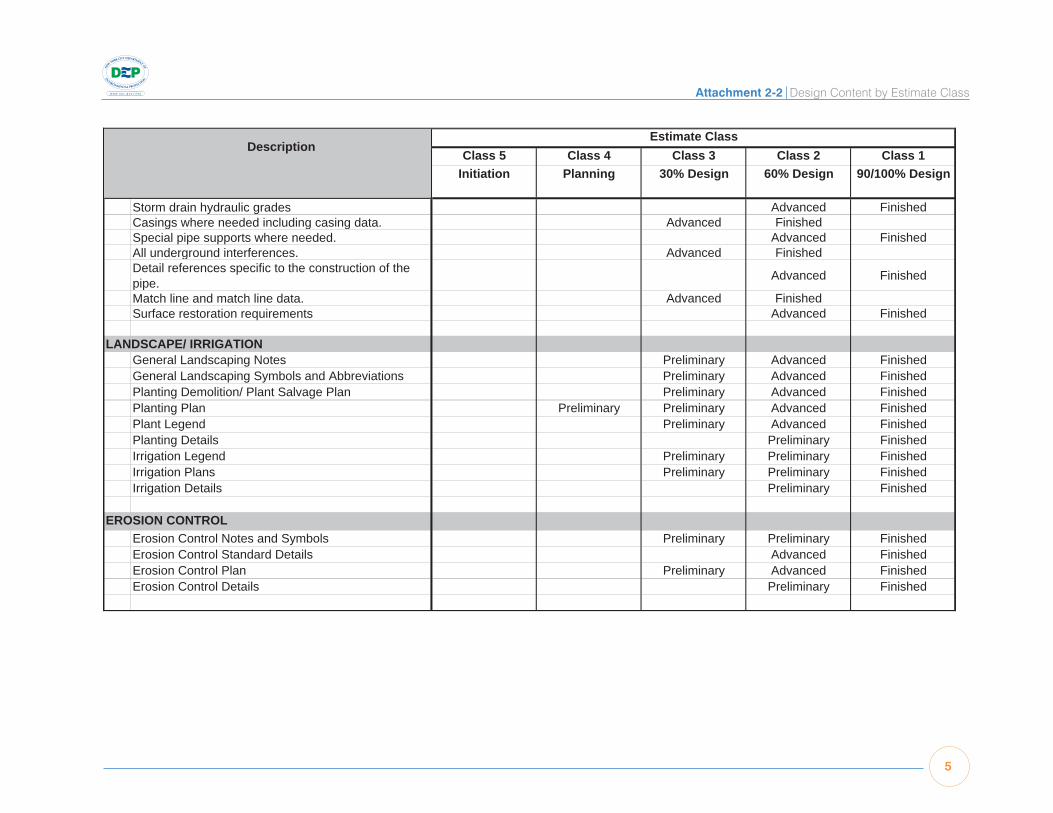
Attachment 2-2 Design Content by Estimate Class
5
ATTACHMENT 2-2DESIGN CONTENT BY ESTIMATE CLASS
Class 5 Class 4 Class 3 Class 2 Class 1Initiation Planning 30% Design 60% Design 90/100% Design
DescriptionEstimate Class
Storm drain hydraulic grades Advanced FinishedCasings where needed including casing data. Advanced FinishedSpecial pipe supports where needed. Advanced FinishedAll underground interferences. Advanced FinishedDetail references specific to the construction of the pipe. Advanced Finished
Match line and match line data. Advanced FinishedSurface restoration requirements Advanced Finished
LANDSCAPE/ IRRIGATIONGeneral Landscaping Notes Preliminary Advanced FinishedGeneral Landscaping Symbols and Abbreviations Preliminary Advanced FinishedPlanting Demolition/ Plant Salvage Plan Preliminary Advanced FinishedPlanting Plan Preliminary Preliminary Advanced FinishedPlant Legend Preliminary Advanced FinishedPlanting Details Preliminary FinishedIrrigation Legend Preliminary Preliminary FinishedIrrigation Plans Preliminary Preliminary FinishedIrrigation Details Preliminary Finished
EROSION CONTROLErosion Control Notes and Symbols Preliminary Preliminary FinishedErosion Control Standard Details Advanced FinishedErosion Control Plan Preliminary Advanced FinishedErosion Control Details Preliminary Finished
ATTACHMENT 2-2 Site Projects JUNE 2008

6
Attachment 2-2 Design Content by Estimate Class ATTACHMENT 2-2DESIGN CONTENT BY ESTIMATE CLASS
Class 5 Class 4 Class 3 Class 2 Class 1Initiation Planning 30% Design 60% Design 90/100% Design
DescriptionEstimate Class
ARCHITECTURALArchitectural General Notes & Symbols Advanced FinishedArchitectural Standard Details Preliminary Advanced FinishedBuilding Code Summary Preliminary FinishedLife Safety Plans & Notes Preliminary FinishedADA Standards (NA where projects are exempt) Preliminary FinishedWall & Partition Types Preliminary FinishedDoor & Finish Schedules, Window Types Preliminary FinishedLaboratory Equipment Schedule (if applicable) Preliminary FinishedToilet Accessories Schedule Preliminary FinishedFurnishings Plan & Schedule (if applicable) Preliminary Advanced FinishedDemolition Plans, Sections & Details Preliminary Advanced FinishedArchitectural Key Plan Preliminary FinishedFloor Plan(s) Preliminary Advanced Advanced FinishedReflected Ceiling Plan(s) Preliminary Advanced FinishedRoof Plan Preliminary Advanced FinishedExterior Building Elevations Preliminary Advanced FinishedElevation Details Preliminary FinishedBuilding Sections Preliminary Advanced FinishedInterior Elevations Advanced FinishedWall Sections Preliminary FinishedProject Specific Details & Sections Advanced Finished
ATTACHMENT 2-2 Site Projects JUNE 2008

Attachment 2-2 Design Content by Estimate Class
7
ATTACHMENT 2-2DESIGN CONTENT BY ESTIMATE CLASS
Class 5 Class 4 Class 3 Class 2 Class 1Initiation Planning 30% Design 60% Design 90/100% Design
DescriptionEstimate Class
STRUCTURALAssumed = Approximate Wall and Slab Thickness; Preliminary = + Rebar; Advanced = + Accessories (e.g. stairs, hatches); Finished = Fully Annotated
General Structural Notes Preliminary FinishedGeneral Standard Structural Details Preliminary Advanced FinishedGeneral Project Specific Details Preliminary FinishedDemolition Plans, Sections & Details Preliminary Advanced FinishedPile Plan Assumed Preliminary Advanced FinishedFoundation Plan Assumed Preliminary Advanced FinishedFloor Plan Assumed Preliminary Advanced FinishedTop Deck or Intermediate Plan Assumed Preliminary Advanced FinishedPartial Plans Preliminary FinishedRoof Framing Plans Preliminary Advanced FinishedMain Sections Assumed Preliminary Advanced FinishedPartial Sections Preliminary FinishedStructural Steel Frame Elevations and Details Preliminary Advanced FinishedMinor Structure Plans, Sections & Details Preliminary Preliminary Finished
MECHANICALStarted = Overall Dimensions; Preliminary = + Major Equipment and Piping (>8"); Advanced = + Accessories (e.g. small piping, supports); Finished = Fully Annotated
Mechanical Standard General Notes Preliminary Advanced FinishedMechanical Standard Details Preliminary FinishedMechanical Equipment Schedules Preliminary Advanced FinishedMechanical Demolition Preliminary Advanced FinishedMechanical Floor Plans Preliminary Advanced FinishedMechanical Sections Preliminary Advanced FinishedMechanical Details Preliminary Advanced Finished
ATTACHMENT 2-2 Site Projects JUNE 2008

8
Attachment 2-2 Design Content by Estimate Class ATTACHMENT 2-2DESIGN CONTENT BY ESTIMATE CLASS
Class 5 Class 4 Class 3 Class 2 Class 1Initiation Planning 30% Design 60% Design 90/100% Design
DescriptionEstimate Class
PLUMBINGPlumbing Standard Details Advanced FinishedPlumbing Schedules Preliminary Advanced FinishedDomestic Riser Diagrams Preliminary Advanced FinishedSanitary Riser Diagrams Preliminary Advanced FinishedNatural Gas Riser Diagrams Preliminary Advanced FinishedPlumbing Floor Plans Preliminary Advanced FinishedPlumbing Sections Advanced FinishedPlumbing Details Finished
HVACHVAC Standard General Notes Preliminary FinishedHVAC Standard Details Preliminary Advanced FinishedHVAC Equipment Schedules Preliminary FinishedHVAC Demolition Preliminary Advanced FinishedHVAC Floor Plans Preliminary Advanced FinishedHVAC Sections Preliminary FinishedHVAC Details Preliminary Finished
FIRE PROTECTIONFire Protection Standard Details Advanced FinishedFire Protection Floor Plans Preliminary Advanced FinishedFire Protection Details Preliminary Finished
ATTACHMENT 2-2 Site Projects JUNE 2008

Attachment 2-2 Design Content by Estimate Class
9
ATTACHMENT 2-2DESIGN CONTENT BY ESTIMATE CLASS
Class 5 Class 4 Class 3 Class 2 Class 1Initiation Planning 30% Design 60% Design 90/100% Design
DescriptionEstimate Class
INSTRUMENTATIONInstrumentation Notes FinishedInstrumentation Symbols and Abbreviations Advanced FinishedInstrumentation Standard Details Advanced FinishedControl System Block Diagram Advanced FinishedCommunication System Diagram Advanced FinishedSecurity System Diagram Advanced FinishedLogic Diagrams Preliminary Advanced FinishedPanel Layout Drawings Preliminary Advanced FinishedLoop Drawings (if required) Advanced FinishedControl Room Plan and Elevations Preliminary FinishedProcess and Instrumentation Diagrams (P&IDs) Advanced FinishedInstrument and I/O Lists Advanced Finished
ELECTRICALElectrical Standard Symbols FinishedElectrical Standard Details Advanced FinishedSite Plan Advanced FinishedDuct Bank Schedule Advanced FinishedManhole, Hand hole and Pull Box Schedule Advanced FinishedSingle Line Diagrams Advanced FinishedElectrical Equipment Elevations Preliminary FinishedSchematic Diagrams Preliminary FinishedLighting Fixture Schedule Advanced FinishedPanelboards/Transformers Advanced FinishedRiser Diagrams for Telephone Systems Preliminary FinishedRiser Diagrams for Fire Alarm Systems Preliminary FinishedConduit Development Preliminary Advanced FinishedConduit Schedule Advanced FinishedDemolition Preliminary FinishedElectrical Equipment Location Plans Advanced FinishedLighting and Receptacle Plans Preliminary FinishedLightning and Grounding Plans Preliminary FinishedMiscellaneous Systems Plans Preliminary Finished
ATTACHMENT 2-2 Site Projects JUNE 2008

10
Attachment 2-2 Design Content by Estimate Class

Chapter 3
Estimate Preparation
Chapter 3
Estimate Preparation


3-1
Chapter 3 Estimate Preparation
Chapter 3 – Estimate PreparationThis chapter describes the general approach to estimate preparation to be used for all BEDC cost estimat-
ing and includes subsections on the following subjects:
• EstimatingSystemRequirements
• EstimatingMethodology
• EstimateStructureandDefinitions
• EstimatingSystemRatesandSupportingCalculations
• EstimateInputs
• EscalationofConstructionCostInputs
• EstimateSections
Estimating System Requirements
AllClass4,3,2and1estimatespreparedforBEDCprojectswithanestimatedconstructioncostof$25Mor
greatershallbeproducedusinganestimatingsystemwiththeminimumfeatureslistedbelow:
• Multiplestandardandcustomreportsusingfilter,sort,andsubtotalfeatures
• Resourcereports(labor,equipment,materials,etc.)
• Variancereportsabletocompareestimatespreparedatvariousstagesofprojectdevelopment
• On-screenreviewcapability,includingsummary/drill-downfeatures
• Multipleresourceratetables
• Updatetheentireestimatebychangingaresourcepriceorrate
• Applyadjustmentfactorstoportionsoftheestimatebasedonaselectioncriteria
SpreadsheetsoftwaremaybeusedforClass5and4estimatesandforsupportingcalculationsofClass3,
2,and1estimates.However,thebodyofClass3,2,and1estimatesmustbepreparedusinganestimating
systemwiththecapabilitieslistedabove,aswellasthecapabilityofproducingthereportslistedinChapter
4ofthisManual.EstimatingsystemsusedtoprepareBEDCClass3,2and1estimatesshallbeoneofthe
following,oranapprovedequal:
• Sage;TimberlineEstimatingExtended
• MC2(ManagementComputerControls);ICE
• HeavyConstructionSystemsSpecialists(HCSS);HeavyBid
• Bid2WinSoftware
• HardDollar
• WinEstimator;WinEst
Approvaltouseanyestimatingsystemotherthanthoselistedabovemustbeobtainedinwritingfromthe
BEDCCostEstimatingDivision.

3-2
Cost Estimating Manual June 2008
EstimatesshallbesubmittedtotheBEDCinhard-copyandelectronicformat.Electroniccopiesmustpro-
videBEDCCostEstimatingDivisionstafftheabilitytomanipulatetheestimate(sort,summarize,drill-down)
aswellasproducecustomreports,butnotnecessarilyrevisetheestimate.
Estimating Methodology
WhensubmittinganestimatetoBEDC,theestimatormustidentifythetypeofestimatingmethodologythat
willbeusedforthevariouscomponentsoftheestimateandprovideback-upmaterialasrequiredtosupport
theaccuracyofthemethod.Thereareavarietyofindustrystandardtechniquestodevelopestimates.The
choiceoftechniqueisdictatedlargelybythelevelofscopedefinitionandtheenduseoftheestimate.In
mostestimates,multiplemethodologiesareusedtoaccountforthevaryingdegreesofscopedefinitionfor
different project elements.Ingeneral,top-downestimatesareusedinearlystagesofprojectdevelopment
whenlessthanabout15to20%ofthetotalscopeisdefinedandaretypicallylimitedinapplicationtoClass
5and4estimates.Top-downestimatesuserulesofthumb,parametricmodels,analogies,orothercost
estimatingrelationships(CERs)toestimatethetotalcost.Thesetypesofestimatingmethodologiescan
behighlyinaccurateandproperlevelsofcontingencymustbeappliedtoaccountforthisestimatingrisk.
Bottoms-upmethodsarecharacterizedbya thorough,detailedanalysisofscopeandtaskcomponents
whichcanbe“rolled-up”toproduceanestimateoftheentireproject.Thisrequiresadetailedworkbreak-
downstructureandpricingofeachworkpackagethatcomprisestheproject.Thismethodrequiresahigher
levelofscopedefinitionandistypicallyreservedforClass3,2and1estimates.
Definitionsof thevariousestimatingmethods typicallyused inprojects is listedbelow.Whereavailable,
definitionswerequoted fromtheAACERecommendedPracticeNo.10S-90CostEngineeringTerminol-
ogy.Themethodologiesarelistedintheorderofacceptableusebasedonscopedefinition.Forexample,
Judgment,GrossCapacity-factored,andParametricModelsshouldonlybeusedinearlyestimates(Class
5or4)whileDetailedUnitCostwithDetailedQuantityTake-Offsarereservedforlaterestimates(Class3,
2,and1):
Judgment–Judgmentisanestimatingmethodbasedonhistoricalexperiencewithsimilartypefacilities
adjustedforknownprojectcomplexitiesandsizeorcapacitydifferences.
Gross Capacity-Factored–“Acostestimatingmethodinwhichthecostofanewfacilityorfacilitycom-
ponentisderivedfromthecostofasimilaritemorfacilityofaknown,butusuallydifferentcapacity.Inthis
method,theratioofcostsbetweentwosimilarfacilitiesisequaltotherationofthecapacitiestakentoan
exponentialfactor.”Capacity-factoredestimatingmethodsaretypicallybasedonaverylimitedamountof
highlevelprojectdefinitionsuchasaveragedryweatherandpeakwetweatherflow(ADWForPWWF)fora
secondarywastewatertreatmentfacility.Agrosscapacity-factoredestimatecouldbebasedonaunitcost
percapacitydevelopedbasedonhistoricalcostdataofsimilarfacilitiesadjustedforlocationandtime.

3-3
Chapter 3 Estimate Preparation
Discipline-Factored –Inearlyestimates,thevariousmajortradesofaprojectaresometimescalculatedas
apercentageofthetotalprojectcosts.Disciplinecostssuchassitecivilworks,electrical,instrumentation,
and landscapinggenerally fallwithinapercent rangeof the totalproject. Forexample, instrumentation
istypicallyintherangeof4to8%ofthetotalprojectcostofatypicalwatertreatmentplantprojectwhile
electricalsystemsaregenerallyintherangeof8to15%ofthetotalprojectcosts.
Parametric Model–“Inestimatingpractice,describesestimatingalgorithmsorcostestimatingrelation-
shipsthatarehighlyprobabilistic innature.Typicalparametricalgorithmsinclude,butarenotlimitedto,
factoringtechniques,grossunitcosts,andcostmodels.Parametricestimatescanbeasaccurateasdefini-
tiveestimates.”Exampleinputsofaparametricmodelforasecondaryclarifiercostmodelmightinclude
PWWF,maximumsurfaceloadingrate,andallowablewaterdepth.Basedonthesehighlevelinputs,the
generaldimensionsofthefacilitycanbeestimatedandwhencombinedwithunitcostsoftheelements,a
parametric-basedcostestimatecanbedeveloped.
Parametricmodelscanalsobeusedtopricecomponentsoftheprojectbasedontheoutputofpreliminary
designinformation.Forexample,afterequipmentrequirementshavebeendefined,powerdistributioncan
beestimatedbasedonthetotalconnectedhorsepoweroftheequipment;buildinglightingandreceptacle/
branchwiringcostscanbeestimatedbasedofthesquarefootageoffloorareaofbuildings.
Semi-Detailed Unit Costs with Assembly-Level Line Items–Boththetakeoffandtheestimateisdone
atthe“assemblylevel”vs.the“line-itemlevel”.ThispracticeistypicalofClass4estimatesandforsome
elementsofClass3estimates.Incaseswhereportionsofthedesigndocumentshavenotprogressedtoa
pointtoallowdetailedtakeoff,anda“go-by”designfromasimilarprojectisnotavailable,itmaybeneces-
sarytousecompositeunitcostsforcertainelementsoftheprojects.Forexample,iftheonlyinformation
availableforabuildingisthesquarefootageandtheuseofthebuilding,itmaybeappropriatetousea
“unitpricefactor”,whichinthecaseofabuildingwouldbe$/squarefootofbuilding.Factorssuchasthis
areknownas“composite”pricesastheyincludeallthecostfortheelementsatthelowerWBSlevels.In
thiscase,thecompositesquarefootpriceforabuilding($/squarefoot),includesthecostforalloftheele-
mentsthatmakeupacompletebuilding(structural,architectural,plumbing,HVAC,electrical,etc.),andthe
estimateisdoneatWBSLevel2only.Asthedesignprogresses,andmoredetailbecomesavailable,itwill
bepossibletoincludemoredetailintheestimateforWBSLevels3through6,butbypricingatWBSLevel
2only,itisunderstoodthatthecostforallelementsbelowthislevelareincludedinthecompositeprice.
Detailed (Line Item) Unit Cost with Forced (Line Item) Quantity Take-Offs – If theclassofestimate
requiresmoredetailthanacapacityfactororcompositeprice,“forced”takeoff,usingcostestimatingre-
lationships,canbeusedtoestimatethequantitiesatthelowerWBSlevels.Forinstance,costestimating
relationshipsfortheaveragesquarefeetofinteriorpartitionpersquarefootofbuildingorthenumberof
sprinklerheadspersquarefootofbuildingcanbeusedtoestimatequantitiesfortheseelements,aswell
theremainingbuildingelements.Anotherexampleofforcedtakeoffispricingforaconcretewall-ifthewall

3-4
Cost Estimating Manual June 2008
dimensionsareavailablebuttherebardetailsarenotavailable,theformworkandconcretevolumecould
bedeterminedusinglineitemdetailandtherebarquantitycouldbedeterminedusinganaveragelbs/cy
factor(poundsofrebarpercubicyardofconcrete).
Detailed (Line Item) Unit Cost with Detailed (Line Item) Quantity Take-Offs–Completedetailedtakeoff
andlineitemestimatingwith100%designdrawingsanddocuments.
Definition Assembly-Level and Detailed (Line-Item) Quantity Take-Offs –The difference between as-
sembly-levelandline-itemdetailasreferencedinthediscussionofestimatingmethodologyabovecanbe
demonstratedbytheexampleofcast-in-placeconcrete.Attheassemblylevel,thetakeoffquantitywould
becubicyards,andtheestimatedetailwouldbemanhours/laborpercubicyard,materialpercubicyard,
equipmentcostpercubicyard,etc.Atthedetailedlinelevel, takeoffquantitieswouldincludeformwork,
constructionjoints,waterstop,buy/placeconcrete,buyplacereinforcingsteel,embeddeditems,cure,etc.
Thedesignandestimatingteammustworktogethertoselectthemostappropriateestimatingmethodolo-
giesbasedon thescopedefinitionandavailabilityofhistoricalcostdataandparametricmodels,again
keepinginmindthatvariousmethodologiescanbeusedforvariousprojectelementsorcomponents.The
teamshouldstrivetousethemostadvancedmethodologieswherepossibletoreduceestimatingerror.The
estimatingteamisrequiredtoreportontheestimatingmethodologiesusedindevelopingtheestimateas
partoftheBasisofEstimateReport(SeeChapter4–EstimateOutputs).
Estimate Structure and Definitions
Inordertoensureconsistencyandtofacilitatereviewandcaptureofhistoricalcostdata,allcostestimates
preparedforBEDCCapitalProjectsmustbepreparedusingaconsistentformat.Thissectiondescribesthe
generalorganizationoftheestimateincludingrequiredCostTypes,Fields(orColumns),EstimateSections,
andLineItemCoding.
Cost Types
Standardcosttypes/categoriestobeusedinallestimatesare:
• Labor
• Material
• Equipment(Construction)
• Subcontracts
• Other

3-5
Chapter 3 Estimate Preparation
Thesecostcategoriesaretypicallythemajorcolumnheadingsinallestimates,andallcostsintheestimate
mustfallintooneofthesecategories.Eachcosttype/categoryisdefinedbelow:
Labor –Allcraftandstaff labor (bothhourlyandsalariedemployees) required tocomplete theproject.
Man-hours is the basic unit ofmeasure for labor and regardless of how labor costs are estimated (by
crewhours,man-months,man-weeks,etc.),totalman-hoursshouldalsobecalculatedandincludedinthe
estimate.
Equipment–Thecostforconstructionequipmentutilizedforconstructionoftheproject.Costsinclude:
• Rental/depreciation
• Maintenance/repaircosts
• Operatingcosts(fuel,oil,grease)
Labortooperatetheequipmentisnotincludedintheequipmentcosttype.Laborformajormaintenance/
repairoftheequipmentisincludedintheequipmentcost.Laborfordailyservicingshouldbeincludedin
thelaborcategory,butasanindirectcost.
Material–Allpermanentandtemporarymaterialusedintheproject.Materialisfurthersubdividedintothe
following categories:
• Permanent material – all material that becomes part of the completed facility other than processequipment
• Processequipment–allequipmentthatbecomespartofthecompletedfacilityandisshownontheequipmentlist
• Temporarymaterial–allmaterialusedand/orconsumedduringconstructionoftheprojectthatdoesnotbecomepartofthecompletedfacility.Examplesincludeplywoodforconcreteformwork,lumberfortemporaryscaffoldingorwalkways,andmaterialsfortemporaryroadways.
Subcontracts – The cost of specialty work performed by subcontractors to the prime contractor. For
allestimatespreparedforBEDC,onlysubcontract itemsperformedonanhourlyortrueunit-pricebasis
shouldbeincludedinthesubcontractcategory.Pricesinthesubcontractcolumnshouldbe“all-in”prices,
includingsubcontractoroverheadandprofit.Allothercosts(notprocuredonatrueunit-pricebasis),even
ifperformedbyasubcontractor,shouldbeestimatedwiththetypicalcostcategories(labor,equipment,
material,andother),butidentifiedasasubcontracteditem.Thisallowsbetteranalysisofon-sitemanpower
levels,risk,escalation,markup,andotherfactorsthatmayaffectthetotalpriceoftheproject.Pricesinthe
labor,equipment,material,andothercosttypecolumnsshouldnotincludesubcontractoroverheadand
profit.Subcontractoroverheadandprofitcanbeaddedinthemarkupsectionoftheestimateasdescribed
laterinthischapter.
Other –Allothercosts thatdonot fit intooneof theothercostcategories(labor,equipment,materials,
subcontracts).

3-6
Cost Estimating Manual June 2008
Fields/Columns in Estimates
Inadditiontoseparatecolumnsforthedollaramountforeachof thecosttypes/categoriesnotedinthe
previoussection,theestimatingsystemmustcontainadditionalfields(columns)toprovideadditionaldata
toeachlineitemestimateincludingquantities,howthelineitemispriced,andcodestoallowtheestimate
tobesortedandsummarizedinvariouscombinations.Notallcolumnswillbeusedinanygivenreport.
Chapter4describesthestandardestimatereportsandwhichcolumnsare includedineachreport.The
fieldsandtheir functionsaredescribedbelow.Theactualnamesofanygivenfieldmayvarydepending
on theestimatingsystembeingusedas longas the fieldperforms thesame functionandprovides the
informationlisted.Fieldnamesinitalicsinthelistbeloware“unitofmeasure”descriptionsassociatedwith
aspecificvaluefield.Theheaderforthesefieldsmaybecombinedwiththeheaderwiththeassociated
valuefield.Forexampletheheaderforthe“EstimatedProductivity”valuemaybecombinedwiththeheader
forthe“ProductivityUnit”aslongasthe“ProductivityUnit”isshownforeachlineitem(e.g250cy/dayor
0.15mh/sf).
Item Level 1/Item Level 2/Item Level 3 – These three fields make up a unique identifier for likeitemsintheestimatingdatabase.Theactualfieldnamesmayvarydependingontheestimatingsys-tembeingused.Thefieldsarehierarchal.Level1 is thehighest leveland isgenerallyorganizedby CSI division or section within the estimatingdatabase.Eachlineitemintheestimatemustbeassignedavalueforeachofthesefieldsinorderto allow grouping of similar items for comparison duringtheestimatereviewprocess.
Description–Descriptionoftheworkincludedintheestimatelineitem.
Take-off Quantity – Physical quantity of theestimate line item determined from the design documents.
Unit –Unitofmeasure(UOM)forthetakeoffquan-tity(e.g.linealfeet,cubicyard,squarefeet,etc.).
Waste–Percentagewasteappliedtothetakeoffquantitytodeterminetheorder(buy)quantityforthematerialfortheestimatelineitem.
Crew–Compositionofthecrew(laborandequip-ment resources) used to perform the work de-scribedbytheestimatelineitem.Crewscancon-sist of multiple craft personnel, and multiple pieces ofequipment,ormaybeasingleresource.
Base Productivity (value)–Productivityistherateatwhichtheworkisperformedbytheresources
(labor and equipment) assigned to the work.Resourcesaretime-related(e.g.manhours,crew-hours,crew-days,man-days,etc.).Productivityisquantified as resources per unit (e.g.manhoursper lineal foot) or units per resource (e.g. cubicyards per crew-day). “Base” Productivity is theproductivity from the estimating organization’shistorical cost library, reference, or experience,and represents the productivity expected underidealconditions.Incaseswherethehistoricalcostistrackedasarange,thebaseproductivityshouldrepresent theaverageormost likelyproductivityunder ideal conditions, before adjustments for project-specificfactors.
Productivity Adjustment –Thevalueinthiscol-umnrepresentsanyadjustment (bypercentage)tothebaseproductivity(seeabove)todeterminetheestimatedproductivityusedforthelineitem.Apositivepercentagecalculatesahigherproductiv-ity(lowercost),andanegativepercentageresultsinalowerproductivity(highercost).Differentlineitems within the estimate including line items for similarwork,mayhavedifferent adjustment fac-torsappliedtothem.
Estimated Productivity–Theproductivityusedto calculate the cost for a given estimate lineitem. With the recommendedprocedureabove,“Estimated Productivity” is “Base Productivity”adjustedbythepercentageshowninthe“Produc-tivityAdjustmentcolumn.

3-7
Chapter 3 Estimate Preparation
Productivity Units – Units associated with the pro-ductivity rates (e.g. mh/lf, cubic yards/crew-hour, sf/mh, etc.)
Labor Quantity – Quantity of labor units (man-hours,crew-hours,man-day,crew-days)usedtoperformthework.
Labor Quantity Unit – Unit of measure for “Labor Quantity”.
Labor Price–Priceof the labor in thecrewperunit of time, expressed as $/manhours, $/crew-day,etc.
Labor Price Unit – Unit of measure for “Labor Price” (manhours, crew-day, etc.).
Labor Manhours –Quantityofmanhoursrequiredto perform the work on the estimate line item,calculatedas“LaborQuantity”multipliedbycrewsize(numberofpersonnelonthecrew).
Labor Amount – “LaborQuantity”multiplied by“LaborPrice”.
Labor Cost/Unit – Labor amount (dollars) pertakeoffunit.
Labor Cost Unit – Unit of measure for “Labor Cost/Unit”.
Labor Rate Table–Codetoidentifythelaborratetableusedtopricethelineitem.
Material Conversion Factor – The “MaterialConversionFactor” isusedwhen thematerial isquantifiedwithaunitofmeasurebutpricedwithanotherunitofmeasure.Forexample,aggregatebasemightbequantifiedby thecubicyard,butpurchasedbytheton.Inthiscase,the“MaterialConversionFactor”wouldbeexpressedas tonspercubicyard(tons/cy).
Material Unit/Unit – Unit of measure for “Material Conversion Factor” (tons/cy, etc.).
Material Waste (yes/no)–Indicatesifthe“Waste”percentage(seeabove)isappliedtothe“TakeoffQuantity”tocalculatethe“MaterialQuantity”usedto determine the cost of the material for the esti-matelineitem.
Material Quantity–“TakeoffQuantity”multipliedby “MaterialConversionFactor”multipliedby (1plus “Waste” factor). This is alsoknownas the“order”quantity.
Material Quantity Unit – Unit of measure for “Ma-terial Quantity”.
Material Price – Price per unit to purchase thematerial. This represents thepriceperunit thatwillactuallybepaid to thesupplierof themate-rial,notthematerialamountdividedbythetakeoffquantity.
Material Price Unit – Unit of measure for “Material Price”.
Material Amount–“MaterialQuantity”multipliedby“MaterialPrice”
Material Cost/Unit – “Material Amount” dividedby“TakeoffQuantity”.
Material Cost Unit – Unit of measure for Material Cost/Unit
Material Tax–Checkmarkoryes/notoindicatewhethertaxisapplicabletothematerialinthelineitem.
Material Subcategory – Code to indicate if the material is permanent material, process equip-ment,ortemporarymaterial/supplies.
Subcontract Price – Cost per takeoff unit ofsubcontractorsworkrequiredfortheestimatelineitem.
Subcontract Price Unit – Unit of measure for “Subcontract Price”.
Subcontract Amount–“SubcontractPrice”multi-pliedby“TakeoffQuantity”.
Equipment Price –Costperunit(hour,day,etc.)oftheequipmentinthecrewusedtoperformthework.
Equipment Price Unit – Unit of measure for “Equipment Price”.
Equipment Amount – “Equipment Price” multi-pliedby“TakeoffQuantity”.
Equipment Rate Table – Code to indicate the equipment rate table used to price the equipment in the line item.
Other Price – Cost per takeoff unit of “Other”costs.
Other Price Unit – Unit of measure for “Other Price”.

3-8
Cost Estimating Manual June 2008
Other Amount – “Other Price” multiplied by“TakeoffQuantity”.
Other Tax –Checkmarkor “yes/no” to indicatewhethertaxisapplicabletothe“other”costinthelineitem.
Total Cost/Unit –Sumof theunitcost(costpertakeoffunit)forLabor,Material,Equipment,Sub-contracts,andOthercosts.
Total Unit – Unit of measure for “Total Cost/Unit”.
Total Amount – Total dollar amount for the esti-matelineitem.TotalAmountisequaltothetotalamountsofLabor,Material,Equipment,Subcon-tracts,andOther.
Percent of Total (optional) -Percentof the totalcost in theestimate representedbyagiven lineor subtotal within the estimate. Typically usedforreviewpurposestoidentifycostdriversintheestimate. Although a value can be assigned toeach line item in theestimate, typicallyonly thepercentagevalueson thesubtotal line itemsareuseful.
Estimate Line Item Coding
Eachlineinthedetailedestimate(attheitemlevel)
shouldbeassignedtheappropriatevaluesforthe
following item codes:
• WBSLevel1;AreaName
• WBSLevel2;ProcessName
• WBSLevel3;SystemName
• WBSLevel4;Group/DivisionName
• WBSLevel5;WorkPackageName
• WBSLevel6;AssemblyName
• SubcontractPackage(to identifywork tobeperformed by subcontractors and assignworktoindividualsubcontractpackages)
• Material Class (for assigning escalation val-ues–seebelow)
• WorkWeek(averagehoursperweekforover-timecalculations)
• QuantitySource(seebelow)
• MaterialPricingSource(seebelow)
• Estimator’sInitials
• DrawingReference
SourcecodesforQuantityandMaterialPricingare
usedforreportingpurposestoratetheaccuracy
oftheestimate.Thesecodesaredefinedbelow.
Quantity Source Codes:1) Detailedtakeoffoffdesigndrawings
2) “Forced” takeoff frompartially completede-sign drawings
3) Takeofffroma“go-by”design(designdraw-ingsfromapreviously-designedfacilitysimilarinsizeinnature)
4) Factoredusingacostestimatingrelationship
5) Assumedbyestimator (nodrawingsorcostestimatingrelationshipavailable)
Material Pricing Source Codes:1) Firmquote(written)
2) Budgetquote(written)
3) Telephonequote
4) Estimated price (using current invoices orpublisheddata)
5) Databaseprices
6) Plugnumbers
Material Classes:
All materials in the database should be assigned
toaBillofMaterialsDescription.BillofMaterials
Descriptions should be grouped into product cat-
egoriesofsimilarmaterialitems.MaterialClasses
should be structured to group materials that would
generallybesubjecttothesamesupply/demand
fluctuationandescalationratesandhavereadily-
availableescalationforecastdataavailable,such
asProducerPriceIndex(PPI)data.ProducerPrice
Index classifications aremaintained by the U.S.
Department of Labor, Bureau of Labor Statistics
andareavailableontheBureau’swebsite,http://
www.bls.gov/ppi/.

3-9
Chapter 3 Estimate Preparation
A partial list of PPI classifications applicable to
BEDC capital projects is listed below:
• Asphaltpavingmixesandblocks
• Roofingasphaltsandpitches,coatings, and cements
• Concreteproducts
• Concretepipe
• Ready-mixedconcrete
• Sand,gravel,andcrushedstone
• Gypsumproducts
• Lumber
• Plywood
• Plasticconstructionproductsandpipe
• Hotrolledbars,plates,andstructuralshapes
• Concretereinforcingbar
• Fabricatedstructuralmetal
• Ironandsteelpipe
• Fabricatedpipeandfittings
• Valvesandfittings
• Pumpsandpumpingequipment
• Fansandblowers
• Industrialmaterialhandlingequipment
• Otherspecialindustryequipment
• Power,distributionandspe-cialtytransformers
• Switchgearandswitchboardapparatus
• Panelboards
• Motorsandgenerators
• Electricallightingequipment
• Buildingwireandcable
• Powerwireandcable
• Commerciallightingfixtures
• Currentcarryingwiringdevices
• Noncurrent-carryingwiringdevices
• Communicationssystemsandequipment
Line Item Coding for Composite Material Prices
To produce several of the required reports, line
items must be coded to a material class and ma-
terial source code in order to calculate escalation
or contingency or other factors associated with
the line item. Whencompositeprices are used
that contain materials that belong to more than
one material class or code, the line item can either
be assigned to the predominant material code,
or a material class that reflects the composition
of theunitpricecanbeused. For instance, for
reinforced concrete, the concrete and the reinforc-
ingsteelwouldnormallybeassigned to twodif-
ferent material classes for calculating escalation
andcontingency.The line itemcanbecoded to
a material class for “reinforced concrete” and the
approximatequantity of reinforcing steel canbe
calculatedusinganaveragelb/cyfactor.

3-10
Cost Estimating Manual June 2008
Estimating System Rates and Supporting Calculations
Thissectiondescribestherequirementsofthevariousratetablesandsupportingcalculationsthatarepart
oftheestimatingsystem.
Labor Productivity
There are three basic methods for estimating labor costs:
1. Unit Price–Laborcost(dollaramount)perunit,notbasedonmanhoursandalaborrate.Forex-ample,theunit-pricemethodforlaborwoulduseanhistoricalpriceof$2.50/sfforanitem,vs.usinganhistoricalproductionrateof0.05manhourspersquarefoot,extendedbyalaborrateof$50.00permanhour.Theunit-pricemethodforpricinglaborshallnotbeusedinestimatespreparedforBEDC.
2. Manhour Pricing–Manhoursperunitorunitpermanhour;forexample5manhours/eachor8sfpermanhour.
3. Crew Pricing–Inthismethod,acrewisbuiltupusingmultipleresources(laborandequipment),andextendedagainstaproductionrate(example;cubicyardsperhour,squarefeetperday,dayspereach,etc.).
Manhourpricing is typicallyusedfor labor-intensiveworksuchasmechanical,electrical,concreteform-
work,etc.Manhourpricingcanperformedthesamewayascrewpricing;byusingasinglelaborresource
asthecrew.However,whenusingmanhourpricing,acrewshouldstillbeusedtoaccountforaworking
foreman.Thiscanbedonebyeitheraddingafractionforemantoacrewwithasinglejourneymanorby
composingthecrewfortheanticipatedforemanration.Forexample,withajourneyman-to-workingforeman
ratiooffour-to-one,thecrewcouldeitherconsistofonejourneymanand0.25foremanorfourjourneymen
andoneforeman.
Crewpricing is typicallyused forcivilworkandotherequipment-intensiveworkbecauseequipment re-
sourcescanbeassigned to thecrew. Inaddition, crewpricingallows for thepossibilityof theneed to
augmentthebasiccrewwithadditionalresources.Forexample,itmaybenecessarytoaddaflaggertoan
excavationcrewtoaccountfortrafficconditionsaroundtheexcavation.Inthiscase,theproductionratecan
staythesame,butthemanhoursperunitandlaborcostwillgoupsincethecrewislarger.
Anotherexampleistruckingassociatedwithanexcavationoperation.Theproductionrateistypicallycon-
trolledbythecapacityoftheequipmentperformingtheexcavation,butthehauldistancetothedisposal
affectsthenumberoftrucksrequiredtosupporttheoperation(asthehauldistanceincreases,moretrucks
arerequired).
Labor Rates
Manhourlaborratesshouldbeestablishedbycraftintheestimatingsystem.Barewagesratesandfringe
benefitsshouldbeobtainedfrompublishedprevailingwagesratesascoveredbytheNewYorkStateLabor
LawStatutes220&230.PrevailingWageRatetablesarepublishedforNewYorkCityandonacounty-by-
countybasisintheremainderofthestate.Laborratesshouldbefully-burdenedtoincludepayrolltaxesand
payroll-basedinsurancesuchasworkerscompensation.Craft-specificworkerscompensationratesshould

3-11
Chapter 3 Estimate Preparation
beused.Forpayrolltaxandinsuranceratesthatareemployer-specific(basedonexperiencefactors),the
defaultpublishedrateshouldbeused.AnexamplelaborratecalculationstableisincludedasAttachment
3-1tothisManual.
Overtime Calculations
Laborcostsmustbeincreasedtoaccountforplannedand/orincidentalovertime.Plannedovertimeoccurs
whenthecontractorplanstoworkotherthana40-hourwork-week,(suchasfive10-hourdaysperweek,
six8-hourdaysperweek,etc.)forsomeorallworkactivities.Incidentalovertimeoccurswhencrewsmust
workpast regularlyscheduledworkhours to finishacriticalactivity,suchasaconcretepour.Overtime
shouldbeincludedintheestimateusingadd-onfactors.(Seethesectiontitled“EstimateSections”later
inthischapterforinstructionsonusingadd-onfactors.)Theadd-oncalculationforovertimekeysoffthe
“WorkWeek”codeassignedtoeachlineitemintheestimate.
Possiblefactorsinclude:
42hours/week–5%incidentalovertime
44hours/week–10%incidentalovertime
48hours/week–schedulesix8-hourdaysperweek
50hours/week–scheduledfive10-hourdaysperweek
60hours/week–scheduledsix10-hourdaysperweek
Otherovertimepossibilitiestoconsiderwouldbe12-hourdays.Thissituationmightoccurwhensupporting
a24-hrperdayoperationandchangingcrewstwiceperday(three,8-hourshifts)isnotfeasible.Overtime
factorsshouldalsotakeintoaccountshiftpremiumssuchas8-hourspayfor7hoursofworkforswingor
nightshifts,orotherpremiumsnot included in thenormalstraight-timerates. Theserulesarenormally
identified in theunion labor agreements. Anexampleworkweekdifferential table for variousovertime
options is included as Attachment 3-2tothisManual.
Material Pricing
Mostconstructionmaterialsmaybegroupedintothreegeneralcategories:
1. Commercially-Available Commodities.Off-the-shelf items thatarecommerciallyavailableandnotsubjecttosignificantregionalvariationinpricesuchas:
– Electrical commodities
– Mechanicalcommodities
– Building commodities
2. Location-Specific Commodities.Materials required insubstantialquantities thataremanufacturedlocallyorregionallyandsubjecttoregionalpricing/availabilitysuchas:
– Concrete
– Aggregates
– Earthworkfillmaterial
– Rebar
– Fabricatedstructuralsteel

3-12
Cost Estimating Manual June 2008
3. Project-Specific Equipment/Materials.Commonlylargeorcustom(not“off-the-shelf”)itemsthatarenotmanufacturedlocallyandaresubjecttonationalorinternationalavailabilitysuchas:
– Largefabricatedpipe
– MajorEquipment
– Largeandspecialtyvalves
Thecostestimator is required toobtain telephonequotesorhave inpossessioncurrent invoices forall
commerciallyavailablecommodities. For location-specificandproject-specificcommodities,budgetary
quotesfromvendorsarerequired.
Decomposition of Composite Prices
Whencompositeunitpricesareused,thereshouldbeadetailedestimatethatcalculatesthatunitprice.
Thedetailedestimateshoulddocumenttheassumptionsforcostestimatingrelationships(forexamplelbs/
cyofrebar,sfofpartitionspersfoffloorarea,etc.),aswellaslaborproductivity,laborrates,materialpricing,
etc.Inaddition,whenusingcompositeunitprices,thepriceshouldstillbebrokenintothebasiccosttypes
(labor,equipment,materials,subcontracts,andother)aswellasmanhours.Thisallowstheunitpricesin
theassemblytobeadjustedforescalation,wagerates,andproductivity.
Equipment Rates (Construction)
Ifactualequipmentrentalratesandoperatingcostsarenotavailable,ratesshouldbeestablishedusingthe
mostcurrentdatafromtheAssociatedEquipmentDistributors(AED)GreenBook.Whenusinghourlyrates
forequipmentthatwillbeassignedtoaworkactivitycontinuously,thehourlyratesshouldbecalculated
asthemonthlyrentalratedividedby173hourspermonth(40hoursperweektimes52weeksperyear
dividedby12monthsperyear).BlueBookweekly,daily,andhourlyrentalratesshouldonlybeusedwhen
theequipmentwillbeusedfordurationsconsistentwithsuchrates.Equipmentratetablesshouldbeset
upwithseparatecategoriesforownershipandoperatingcoststoallowadjustmentsand/orescalationfor
operatingcostsduethepotentialvolatilityoffuelcosts.
Estimate Inputs
Attachment 3-3summarizesestimatorinputsforeachclassofestimateforthetypicalcostdriversinmu-
nicipalwaterandwastewaterwork.Thesekeycostdriversincludethefollowing:
• Equipment(Attachment3-3A)
• Earthwork(Attachment3-3B)
• StructuralConcrete(Attachment3-3C)
• Electrical(Attachment3-3D)
• ProcessPiping(Attachment3-3E)
• IndirectCosts(Attachment3-3F)

3-13
Chapter 3 Estimate Preparation
The tables in Attachment 2-1showthedescriptionofeachassembly,theunitofmeasure,andtherequired
inputforestimateClasses2,3,and4.ForClass5estimates,assemblyleveldetailisnottypicallyused.
Class1estimateswilltypicallyuselineitemlevelofdetail.The“requiredinput”columnisbasedonthe
designinformationthatistypicallyavailableatthestageoftheprojectdevelopmentthatcorrespondswith
thatestimateclass.Where the required input is less thanwhat is required forcompletedetailed takeoff
usingtheassembly,theestimatormayeitheruseacompositepriceasdescribedabove,orgeneratethe
requiredinputusingforcedtakeoffs.
Escalation of Construction Cost Inputs
Escalationofconstructioncostinputsshallbeincludedinallestimates.Theassumedescalationiscon-
sideredanelementof thebasecostestimateandnotcontingency.Escalationcontingencyisaddedto
accountforthepossibilitythattheamountofescalationincludedinthebaseestimatewillbeexceeded.
Duetothevolatilityofvariouskeyconstructionmaterials,laborandmaterialescalationshouldbecalculated
independently.Basecostestimatesshouldincludedcurrentlaborandmaterialpriceswithescalationcal-
culatedandshownseparatelyasoutlinedbelow.EscalationcalculationsaretobeincludedintheBasisof
EstimateReport(SeeChapter4–EstimateOutputs).
Material Escalation
The base estimate should be prepared using current prices for all materials and supplies included in the
estimate.Asnotedearlierinthischapter,allmaterialitemsintheestimateshallbeassignedtoamaterial
classthatcorrespondstoitsassociatedPPI(ProducerPriceIndex)escalationindex.ProducerPriceIndex
classificationsaremaintainedbytheU.S.DepartmentofLabor,BureauofLaborStatisticsandareavailable
ontheBureau’swebsite,http://www.bls.gov/ppi/.
Differentclassesofmaterialthatrepresentasignificantportionoftheestimatemaybesubjecttodifferent
marketvolatilityandshouldbeescalatedusingdifferentrates.Aspartofthisanalysis,amaterialresource
reportbymaterialclassshouldbepreparedandincludedwiththeestimatebackup.Materials forwhich
aspecificescalationindexisnotavailableandarenotasignificantportionofthetotalmaterialcost,may
beassignedtoageneralescalationindex,aslongasaminimumof80%ofthetotalmaterialcostinthe
estimateisassignedtoaspecificescalationindex.Escalationformaterialsshallbebasedondatafroma
recognizedproviderofpricingdata,suchasGlobalInsight,orasimilarserviceacceptabletotheBEDCCost
EstimatingDivision.Forecastdatamustbeupdatedatleastannuallybutpreferablyquarterly,especiallyfor
criticalmaterials.Updatesshallbeobtainedtocorrespondwiththeanticipateddurationoftheprojectorfor
theperiodinwhichthematerialsareexpectedtobepurchasedbythecontractor.
Materialescalationshallalsobeanalyzedusing theproposedconstructionschedule. Differentmaterial
andequipmentitemsmayrequiredifferentescalationfactors,dependingontheanticipatedpurchasedate.
Forinstance,long-leadtimespecialtyequipmentwilltypicallybepurchasedbythecontractorshortlyafter

3-14
Cost Estimating Manual June 2008
receivingaNotice toProceed. In thiscase, theestimatedcost for theequipmentdoesnotneed tobe
escalated past this date. Othermaterialsmay be subject to escalation throughout the duration of the
project.Forexample,ready-mixconcretepricesaretypicallysubjecttoescalationatleastannually,evenif
thecontractorhascommittedtotheentireconcreterequiredfortheworkatthebeginningoftheproject.
Materialescalationshallbeshownasseparate line itemson theestimatesummarysheet,one lineper
escalationpercentage,andthesupportingcalculationsshallbeincludedintheBasisofEstimateReport
(seeChapter4–EstimateOutputs).
Labor Escalation
Ifavailable,laborratesshouldbeescalatedbasedonfutureincreasesincludedintheappropriateunion
laboragreements.Ifthisinformationisnotavailableorifcontractswillexpirepriortothescheduledendof
theproject,forecastsoflaborrateincreasespreparedbyarecognizedindustryforecastservice(e.gGlobal
Insight)shouldbeused.Escalationshouldbebasedonanestimateofthenumberofmanhoursthatwillbe
expendedduringeachwageperiod,typicallyannually.
Laborescalationshallbeshownasaseparatelineitemontheestimatesummarysheetandthesupporting
calculationsshallbeincludedintheBasisofEstimatedocument(seeChapter4–EstimateOutputs).
Escalating Composite Prices
Where theestimate, orportionsof theestimate, arenotpreparedat the line itemdetail level (for early
estimatesbasedonfactoringorcompositeunitpricesonly),escalationshouldbecalculatedbydecompos-
ing the price to the same labor and material components that correspond to the escalation factors used
indetaillineitemestimates.Completedestimatesfromhistoricalprojectsshouldbeusedtofacilitatethe
decompositionoftheprices.Asimilarmethodshouldbeusedforescalatinghistoricalcompositepricesto
currentpricing.
Estimate Sections
All estimates should be structured with separate sections for each of the following major cost
classifications:
1. DirectCosts
2. IndirectProjectCosts
3. Add-ons
4. ContractorMarkup
5. ContractorBonds/Insurance
6. ProjectContingency

3-15
Chapter 3 Estimate Preparation
Definitionsforeachofthesecostclassificationsareshownbelow.
Direct Costs
PerAACERecommendedPractice10S-90,directcostsare:“Costsofcompletingwork thataredirectly
attributabletoitsperformanceandarenecessaryforitscompletion.1)Inconstruction:thecostofinstalled
equipment,material,laborandsupervisiondirectlyorimmediatelyinvolvedinthephysicalconstructionof
thepermanentfacility.”
Directcosts includeall craft laborextending from theworking foreman leveldown, thataredirectlyas-
sociatedwiththephysicalworkactivity. Non-workingcraftsupervisionabovetheworkingforemanlevel
(generalforeman,mastermechanics,shopstewards,superintendents,etc.)andallotherstaffsupervision
shouldbeincludedinindirectprojectcosts.
Allpermanentmaterials(materialsthatbecomepartofthecompletedfacility/project)areincludedindirect
costs.Inaddition,temporarymaterials/suppliesthataredirectlyassociatedwithaphysicalworkitemarein-
cludedindirectcosts.Examplesoftemporarymaterials/suppliesthatareincludedindirectcostsinclude:
• Materials/suppliesforconcreteformwork
• Concretecuringcompound
• Lumberandstructuralsteelusedfortemporarysupportsandfalsework
• Shoringforastructureexcavationandrecoveredwhennolongerneeded
Temporarymaterialsandsuppliesthatarenotdirectlyassociatedwithaphysicalworkitemareincludedin
indirectprojectcosts.Examplesinclude:
• Scaffolding/walkwaysusedbyallcraftsforvariousworkitems
• Temporaryenclosuresandheatingforallcraftsforvariousworkitems
• Materialsforatemporarybridgeconstructedforaccesstothesite
Constructionequipment thatcanbedirectlyattributedtothephysicalworkandassignedtothecrewis
consideredadirectcost.Examplesofequipmentthatshouldbeinincludedindirectcostsinclude:
• Excavatingequipment
• Cranesassigneddirectlytoaspecificcrewandusedforaspecificworkactivity
• Compressorsassignedtoanindividualcrew
Examplesofequipmentthatshouldbeincludedinindirectprojectcostsare:
• Forkliftsatacommonstagingfacilitythatsupportsallworkactivities
• Cranes(fixedandmobile)thatsupportmultiplescraftsandworkactivities
• Flatbedtrucksusedforgeneralpurposes
• Centralizedcompressedairsystems
• Centralizedtemporarypowerfacilities

3-16
Cost Estimating Manual June 2008
Indirect Project Costs
AACERecommendedPractice10S-90definesindirectcostsas;“Costnotdirectlyattributabletothecomple-
tionofanactivity.”Inconstruction,allcostwhichdonotbecomeafinalpartoftheinstallation,butwhichare
requiredfortheorderlycompletionoftheinstallationandmayinclude,butarenotlimitedto,fieldadminis-
tration,directsupervision,capitaltools,startupcosts,etc.”Indirectprojectcostsaresometimesreferredto
as“generalconditionscosts”,“generalexpensecosts”,“fieldoverheadcosts”,etc.Forconsistency,these
costsshouldalwaysbeidentifiedas“indirectprojectcosts”inestimatespreparedforBEDC.
Indirectprojectcostscannotbeallocatedtophysicalworkitemsastheyareeithernotrelatedtotheoverall
volumeofworkorcannot logicallybeallocated toanyonephysicalwork item. Essentially theyareall
project-relatedcosts(otherthanbondsandinsurance)thatcannotbeattributeddirectlytoaphysicalwork
activityandgenerallyinclude:
• Mobilization/demobilization
• Job-sitestaff(management,engineering,supervision,qualitycontrol,safety,support,etc.)
• Temporaryfacilitiesandstructures(offices,warehouses,safety/first-aid,toolsheds,fuel/repairfacilities,etc.)
• Temporarysupportfacilitiesandutilities(barricades/fencing,parking/roadways,storageyards,signs,scaffolding,enclosures,etc.)
• Temporaryutilities(telephone,water,power,compressedair)
• Jobofficeexpenses
• Financeexpenses
Notall indirectprojectcostswillbeincurred/expendedattheprojectsite.Dependingonthesizeofthe
projectandthecontractor’sorganization,someproject-relatedfunctionsmaybeperformedatthecontrac-
tor’shomeoffice(e.g.projectcontrols,changeorderestimating,projectaccounting,etc.).Eventhough
thesefunctionsareperformedatthehomeoffice,sincetheyaredirectlyrelatedtotheproject,theyarestill
consideredproject-relatedcostsandshouldbeincludedintheestimateasindirectprojectcosts.
Manyindirectcostsareone-timecosts(mobilization/demobilization)orstrictlytime-relatedcosts(e.g.rent
ofofficetrailersorsecurityguards)andareindependentofthevolumeofworkperformedduringanygiven
period.Acomprehensivechecklistofallpotentialindirectprojectcoststobeincludedintheestimatecan
befoundinAttachment3-4ofthisManual.
Someindirectcostsareveryeasilycalculatedaspercentagesofothercostsandarethereforeincludedin
the“Add-ons”sectionoftheestimatesummary.

3-17
Chapter 3 Estimate Preparation
Add-Ons
Add-onsareusedinestimatestocalculatecostsof itemsthataretypicallyapercentageofothercosts.
Salestaxasapercentageofmaterialsinanexample.Otherexamplesinclude:
• Smalltoolsandsuppliesasa%oflabororasadollarpermanhourrate
• Overtimeasapercentageoflaborcost
• Subcontractormarkup
• Escalation
Add-onsareusefulbecausetheyautomaticallyrecalculatetheamountoftheadd-onifthecostonwhich
itwasbasedchanged.Theyalsoallowquickrecalculationofanestimateiftherateassociatedwiththe
add-onchanges(escalationincreasedfrom6%to8%forinstance).
Add-ons can also be used to calculate contractormarkup/profit, aswell as bond, and revenue-related
insurancecosts.However,thesecostsshouldbeshownintheirrespectivesectionsandnotintheadd-ons
sectionoftheestimatesummary.
Contractor Markup
Anamountincludedinthecontractor’sbidpriceinadditiontoallproject-relateddirectandindirectcoststo
accountforprofit/feeandtocoveraportionofthecompany’shomeofficeoverhead.
Contractor Bonds/Insurance
Thisestimatesectionincludesthecosttoprovidepaymentandperformancebondsaswellastherevenue-
basedinsurance(typicallybuildersriskandgeneralliabilityinsurance).Worker’scompensationinsurance
shouldbeincludedinthelaborrates.
Contingency
EstimatingcontingencyisincludedasaseparatechaptertothisManual(Chapter5–Contingency).

3-18
Cost Estimating Manual June 2008

Chapter 3
Attachments


Attachment 3-1 Sample Wage Rate Calculation
1
Attachment 3-1 Sample Wage Rate CalculationATTACHMENT 3-1
SAMPLE WAGE RATE CALCULATION
Craft: United Brotherhood of Carpenters and JoinersLocal: District Council of New York City and Vicinity
Classification: Carpenter-Building CommercialEffective Dates: 10/1/2007 through 6/30/2008
Normal Work Hours per Day (A) 7Average Weeks/Yr 52Days per Week ( C ) 5Hours per Year (A X B X C) 1820
ST Shift 1.5 OT 2.0 OT41.710$ 53.63 62.57 83.4348.120$ 60.04 68.98 89.93
Fringe Calc. Method PercentageDollars per hour worked N/A 10.00$ 10.00$ 10.00$ 10.00$ Dollars per hour worked N/A 9.81$ 9.81$ 9.81$ 9.81$ Dollars per hour worked N/A 6.60$ 6.60$ 6.60$ 6.60$ Dollars per hour worked N/A 0.70$ 0.70$ 0.70$ 0.70$ Dollars per hour worked N/A 6.41$ 6.41$ 6.41$ 6.41$ Dollars per hour worked N/A 0.04$ 0.04$ 0.04$ 0.04$ Dollars per hour worked N/A 1.00$ 1.00$ 1.00$ 1.00$ Dollars per hour worked N/A 0.06$ 0.06$ 0.06$ 0.06$ Dollars per hour worked N/A 0.20$ 0.20$ 0.20$ 0.20$
34.82$ 34.82$ 34.82$ 34.82$
Wage Plus Fringe 76.53$ 88.45$ 97.39$ 118.25$
Taxable Wage CapFICA/S.S. 6.200% Note 1 2.98$ 3.72$ 4.28$ 5.58$ FICA/Med 1.450% N/A 0.70$ 0.87$ 1.00$ 1.30$ State U.I. 9.500% 8,500$ /Year 0.44$ 0.44$ 0.44$ 0.44$ Fed U.I. 0.800% 7,000$ /Year 0.03$ 0.03$ 0.03$ 0.03$ Workers Compensation 12.670% 750$ /Week 2.72$ 2.72$ 2.72$ 2.72$
WC Classification 54036.87$ 7.78$ 8.47$ 10.07$
83.40$ 96.23$ 105.86$ 128.32$
NOTES:1) FICA cap not used in calculations.2) Shift work (2nd and 3rd shift) rate based on 9 hours pay for 7 hours work.3) 1.5 OT for weekday hours over 7 and all day Saturdays4) 2.0 OT for Sundays and Holidays
NY DCC Labor/ManagementInt'l Brotherhood of CarpentersSupplemental PensionSupplementalVacation
Fringe Benefits
Taxable WageHourly Wage
Welfare FundPension FundAnnuity FundA.J.R.E.I.F.
Total Fringe
Taxes & Insurance
Total Hourly Rate
Total Taxes and Insurance
ATTACHMENT 3-1 JUNE 2008

2
Attachment 3-1 Sample Wage Rate Calculation

Attachment 3-2 Sample Work Week Differential Calculations
1
Attachment 3-2 Sample Work Week Differential CalculationsATTACHMENT 3-2
SAMPLE WORK WEEK DIFFERENTIAL CALCULATIONS
Hrs/Wk Amt/Wk Hrs/Wk Amt/Wk Hrs/Wk Amt/Wk Hrs/Wk Amt/Wk Hrs/Wk Amt/Wk Hrs/Wk Amt/WkRate Description Ave Rate/Hr
Straight Time 83.4 35 2919 35 2919 35 2919 35 2919 35 2919 35 2919Overtime-Day Shift 105.86 0 0 5 529.3 15 1587.9 0 0 0 0 15 1587.9Straight Time-Middle Shift 96.23 0 0 0 0 0 0 35 3368.05 35 3368.05 35 3368.05Overtime-Middle Shift 105.86 0 0 0 0 0 0 0 0 0 0 15 1587.9Straight Time-Night Shift 96.23 0 0 0 0 0 35 3368.05 0Overtime-Night Shift 105.86 0 0 0 0 0 0 0 0
0 0 0 0 0 0 0
Total per Week 35 2,919.00 40 3,448.30 50 4,506.90 70 6,287.05 105 9,655.10 100 9,462.85
Average $/HR 83.4 86.21 90.14 89.82 91.95 94.63Premium $/HR vs Base N/A 2.81 6.74 6.42 8.55 11.23% premium vs. Base N/A 3.37% 8.08% 7.70% 10.25% 13.47%
Alt Week 4 Alt Week 5Base Week Alt Week 1 Alt Week 2 Alt Week 3
2 shifts; 10-hrs/day; 5 days/wk
Single shift; 7-hrs/day; 5 days/wk
Single shift; 10-hrs/day; 5 days/wk
2 shifts; 7-hrs/day; 5 days/wk
3 shifts; 7-hrs/day; 5 days/wk
Incidental overtime, 1-hr/day; 7-hrs/day; 5
days/wk
ATTACHMENT 3-2 JUNE 2008

2
Attachment 3-2 Sample Work Week Differential Calculations

1
Attachment 3-3 Estimator Inputs
Attachment 3-3A EquipmentIn process plants, equipment is one of the most significant cost drivers and must therefore be identified
and defined early in the design phase. In addition to being identified on the drawings, equipment must be
defined using the followings:
• EquipmentList
• EquipmentSpecifications
Equipment List
The equipment list should be started no later than the Class 4 estimate phase and updated as required
throughout the remainder of design. At a minimum, the following equipment must be included on the
equipment list:
• AllequipmentshownontheProcessFlowDiagramsandProcessandInstrumentationDiagrams
• Allvalvesof>6-inchesindiameter,gates,andmeters
• AllequipmentshownontheelectricalSingle-LineDiagrams
• AllequipmentshownonHVACschematics
The equipment list should include the item title, type of equipment, installation location, equipment number
(fromP&ID)drivetype(rotatingequipment),actuatortype(forvalvesandgates)powerrequirements,key
designcriteria(size,dimensions,capacity,etc.),specificationsection,andP&IDReferenceSheet.
MinimumrequirementsfortheEquipmentListandSpecificationsforallequipmentbyestimateclassare
shown in the table below:
EstimatEClass
EquipmEnt list ContEnts(inCludE all EquipmEnt shown on) spECifiCations
sourCE ofpriCing data
5 Not started Not Started Historical data
4 Process Flow Diagrams Not StartedBudget quotes for major process equipment; Historical data for others
3Completed P&ID’sPreliminary Electrical Single-Line DiagramsPartially- completed HVAC Schematics
DraftVendor budget quotes for all equip-ment
2
Completed P&ID’sCompleted Electrical Single-Line DiagramsCompleted HVAC SchematicsAdditional minor equipment
FinalWritten quotations for major process equipment; vendor budget quotes for all other
1 Additional minor equipment (e.g. small sump pumps)
Final

2
Attachment 3-3 Estimator Inputs
Attachment 3-3B Earthwork
General
Dependingontheparticularscopeoftheproject,earthworkcanbeamajorcostdriverinconstruction.Be-
cause of the wide range of existing site conditions, soil types, groundwater, staging/phasing requirements,
andconstructionmethods/equipment,earthworkisalsoamajorsourceofvariabilityinestimates.Inad-
dition,duetothepotentialforencounteringunknownorunanticipatedconditions,evenaftergeotechnical
investigationshavebeencompleted,earthworkrepresentsamajorriskfactor.
Major Earthwork Work Packages
Workpackageswithinthegeneral“earthwork”classificationcanbegroupedintothreecategories:
• MassExcavation&Fill/SitePreparation/OverlotGrading
• MajorStructureExcavationandBackfill(perstructure)
• Other(roadways,siteworkfinishes,etc.)
Asthemajorityofthecostwilltypicallybeinthefirsttwocategoriesfortreatmentplantwork,thissection
focuses on those categories only.
The“MassExcavation/SitePreparation”workpackageincludesallworkrequiredtoadjustthesiteeleva-
tionstoapproximatefinalgrade(orlowerifstructureexcavationwillbewastedonsite).“MajorStructure
ExcavationandBackfill”includestheexcavation/backfillspecifictoagivenstructureorareaafterthemass
excavationhasbeenperformed.Excavationandbackfillspecifictootherprojectelements(pipe,ductbank,
smallstructures,etc)isincludedwitheachstructureorelement.
Excavation Production Table
Tofacilitateestimatereview,anExcavationProductionTableshouldbecompletedandincludedintheBasis
ofEstimatedocumentforallmajorexcavationestimates.TheExcavationProductionTablesummarizesthe
quantitiesdeterminedbythedetailedexcavationtakeoffanddocumentstheassumptions(method,crew,
andproductivity)forthemajorelementsoftheexcavationestimate:
• Excavate
• LoadandHaul
• PlaceandCompact
Line items in theExcavationProduction Table should be structured to allow the reviewer to determine
where the excavation occurs, where the material is transported, excavation methods, placement/compac-
tion methods, and associated production rates. Total quantity should be based on the amount to be
excavated and/or fill required. Individual line item within the table represent quantities for separate areas or

3
Attachment 3-3 Estimator Inputs
structures that will use the same methods, crew, production rates, haul distances, disposal methods, etc.
Forexample,materialthatwillbemovedtoatemporarystockpilelocationshouldbeonaseparatelineitem
thanmaterialthatwillgostraighttoapermanentfilllocation,orbehauledtoanoffsitedisposalarea.Only
quantities that use the same method, crew, disposition, and production rates should be on the same line.
The combination of the various methods for these elements will depend on a number of factors, including:
• Distancebetweenexcavationsiteandspoil/stockpilesite
• Timingofexcavationvs.backfill
• Materialtype
• Equipmentavailability
Ifmaterialmustdisposedoff-site,anyrequireddisposal/tippingfeepercubicyardortonshouldbeshown
for each affected line. If the fee is on a per ton basis, the conversion from cubic yards should also be shown
in this column.
Dependingontheconditions,notalloftheelementsmaybeapplicabletoagivenoperation.Forexample,
iftheexcavationforasmallstructureisperformedbyabackhoethatisabletosimplysidecastthematerial
which is laterusedforbackfillat thesamelocation, theremaynotbea load/haulcomponent. Inother
cases, the excavator may be able to place the material directly in the hauler such that a separate loading
operation is not required.
Incaseswhereallthreeelements(excavate,load/haul,place/compact)areperformedsimultaneouslyand
at the same rate, this could theoretically be considered as a single crew. In this case, individual crew
members and equipment should still be assigned to each element to facilitate production analysis and
review.Onlyincaseswherethesamepieceofequipmentperformsmultipleelements(suchasascraper
operation)shouldthecrewsbecombined.
Siteconditionsmayrequireadditionalprocessingofthematerialinadditiontothethreetypicaloperations
(excavate,load/haul,place/compact).Additionaloperationsmayinclude:
• Screening
• Drill/Blast
• SoilConditioning
• Disking/Drying
• Mixing
• Shoring/SoilStabilization
TheseadditionaloperationsshouldbeshownasseparatelineitemsintheExcavationProductionTable,
and since they represent “double handling” of thematerial, thequantitieswill be in addition to typical
excavation quantities.

4
Attachment 3-3 Estimator Inputs
Support Operations
Many other items that are not necessarily driven by the excavation quantities must also be included in the
earthworkestimate.Theseinclude:
• ErosionControl
• Haulroaddevelopment
• Haulroadmaintenance
• Dustcontrol
• Stockpilemaintenance
• Weedcontrol
• Dewatering
Since these itemsmaynotbe “quantity-driven” (notproportional to theexcavationquantities) theywill
typicallynotbeincludedinaunitpriceforexcavation,andarenotincludedintheExcavationProduction
Table.
Structure Excavation Table
AStructureExcavationTableshouldbecreatedforallmajorstructureexcavationandbackfilltodocument
theassumptionsmadeforquantitytakeoffs(excavationdepth,sideslopes,sideclearance,etc.),andto
serveasachecklisttoensureallrequiredelementshavebeenincluded.Forsimply-shapedexcavations,
thetablemayalsobeusedtoperformthequantitytakeoff.Quantitiesandassumptionsgeneratedbythe
StructureExcavationTableshouldbepostedtotheExcavationProductionTable.
Quantity Determination for Each Estimate Class
Sinceearthworkrepresentsamajorcostdriver,estimatesshouldbepreparedusingthemostdetailedin-
formation available. The minimum level of detail that should be used for each estimate class is summarized
below.
Class 5–Earthworkquantitiescanbeassumedusinga“go-by”design,historicaldata,ormaybeincluded
inthecapacityfactorusedtopricethework.
Class 4–Majorearthworkquantitiesmaybedeterminedusing thepreliminarysitegradingand facility
layout plans coupled with the hydraulic profile.
Class 3–Majorearthworkquantitiescantypicallybefinalizedatthispoint.Preliminaryquantitiesforother
earthworkpackages(roads,finishes)shouldbeestimatedatleastattheassemblylevel.
Class 1/2–AllearthworkquantitiesshouldbefinalizedintheClass2estimate.

5
Attachment 3-3 Estimator Inputs
Attachment 3-3C Structural ConcreteStructuralconcrete typically representsasignificantcostdriver forwaterandwastewater facilities. The
percentageofthetotalcostassociatedwithconcretewillvarydependingontheparticularprojectscope.
Where concrete will be a significant cost driver, the estimate should be based on the most detailed informa-
tionavailable.Wheneverpossible,estimatesforstructuralconcreteshouldbebasedondetailedtakeoffs,
either from thedesigndocuments from theactualproject,ordocuments fromasimilar facility (“go-by”
design)adjustedtoapproximatetheactualproject.
Forced Takeoff for Structural Concrete
If details arenot available, either from thedesigndocumentsor “go-by”designdocuments, itmaybe
necessarytouse“forcedtakeoff”(costestimatingrelationships)tocalculateconcretequantities.Typically,
therearetwolevelsofforcedtakeoff:
• Volumeofconcretebasedonaprojectdesignparameter
• Quantityofconcrete-relatedcomponentsbasedonconcretevolume
Components for Structural Concrete
Estimatesdoneatline-itemdetaillevelshouldcontainataminimumthefollowingcomponents:
• Concretevolume(cy)
• Formwork(sf)
• Shoring(cf)
• Finishing(sf)
• Reinforcing(tons)
• Accessories
– Waterstop(lf)
– Embeddedmisc.metal,includinganchorbolts(lbs)
– Expansion/contractionjoints(lf)
– VaporBarrier(sf)
– Hardner/Sealer(sf)
– Formliners
– Admixtures
– Keyways
– Blockouts
In addition to the components listed above, line items should be identified by the following categories:
• Concreteby:
– Strength/mixdesign
– Placementmethod

6
Attachment 3-3 Estimator Inputs
• Buggy
• Truck
• Crane
• Pumped
– Assembly
• Walls
– Straight
– Circular
– Battered
• SlabonGrade
• ElevatedSlabs
– SuspendedFormed
– SlabonMetalDeck
• Beams(ifnotintegralwithslabs)
• Columns
– Square
– Round
• Footings
– Continuous
– Pad
• EquipmentPads
• Stairs(castinplaceconcrete)
• CurbsandMiscellaneous
• Formworkbytype
– Walls
• Gang
• Handset
• Straight
• Circular
• Battered
– Elevatedslabs
– SlabonGrade
• <12”
• 12”to24”
• >24”(RaftType)
– Columns
• Square
• Round

7
Attachment 3-3 Estimator Inputs
– Beams(integralornon-integral)
– Footings
• Continuous
• Pad
– Stairs
– Equipmentpads
– Curbs
• Finishingbytype
– Horizontal
• Float
• Trowel
– Vertical
• PointandPatch
• SackRub
Composite Prices
Whendetailsarenotavailabletoperformtakeoffattheassemblyorcomponentlevel,compositepricesmay
be generated. Composite prices per cubic yard of concrete are generated by using an average quantity
for the various components, and pricing the average quantities with current labor and material rates. This
composite cost is then extended against the concrete quantity to obtain the total cost.
Typical composite prices include:
• Costpercubicyardforallstructuralconcrete,whenquantitiesbyassemblyarenotavailable.
• Costpercubicyardbyassemblytype.
Composite prices should be generated to allow calculation of all cost types (labor, permanent material,
equipment, supplies, etc.) andman-hours. Also,becauseof thepossibility of large swings inmaterial
prices, concrete and reinforcing steel should be itemized separately for all estimates (i.e., even though a
compositepriceisusedtogeneratecosts,thequantityandcostofreinforcingsteelshouldbebrokenout
separately).Ifcompositepricesareused,thesupportingcalculationsandpricingshouldbeincludedin
theBasisofEstimatedocuments.
Assemblies
Inordertofacilitatescopeandpricingreviews,concretetakeoffsandestimatesshouldbeperformedand
summarizedbythefollowingassemblies(WBSLevel4).Small/insignificantquantitiesmaybesummarized
inthe“other”assemblycategory.Large/significantquantitiesmayrequireanadditionaldesignation.Total
and unit costs should be shown at the assembly level, with cubic yards as the unit.

8
Attachment 3-3 Estimator Inputs
Takeoff/Estimating Requirements by Estimate Class
Targetrequirementsforconcretetakeoffandpricingarelistedbelowforeachestimateclass.Thesearethe
targeted requirements and whenever possible, revert to the following preferences:
• Detailedtakeoffofallcomponents(DTO)
• Detailed takeoffofvolumeand formwork; forced takeoff (FTO)of remainingcomponentsbasedonconcrete volume
EstimatEClass
targEt linE itEm dEtail takEoff mEthod priCing mEthod
5 Total CY of Concrete Forced takeoff of total volume Composite cost/cy
4 CY of Concrete by Assembly Force takeoff of volume by assembly Composite cost/cy by assembly
3 See table below See table below See table below
1 and 2 Complete line item detail for all components
Detailed takeoff of all components Line item pricing for all components
Class 3
assEmbly
VolumE/ plaCEmEnt formwork finishing
rEinforCing stEEl
aCCEssoriEs/dEtails
Quantity Pricing Quantity Pricing Quantity Pricing Quantity Pricing Quantity Pricing
Slab on Grade DTO DTO DTO lbs/CY FTO/CY
Walls DTO DTO DTO lbs/CY FTO/CY
Elevated Slabs DTO DTO DTO lbs/CY FTO/CY
Beams DTO DTO DTO lbs/CY FTO/CY
Columns DTO DTO DTO lbs/CY FTO/CY
Column Footings DTO DTO DTO lbs/CY FTO/CY
Continuous Footings DTO DTO DTO lbs/CY FTO/CY
Stairs FTO Comp In Comp In Comp In Comp In Comp In Comp In Comp In Comp In Comp
Pipe Supports FTO Comp In Comp In Comp In Comp In Comp In Comp In Comp In Comp In Comp
Equipment Pads FTO Comp In Comp In Comp In Comp In Comp In Comp In Comp In Comp In Comp
Other/Miscellaneous FTO Comp In Comp In Comp In Comp In Comp In Comp In Comp In Comp In Comp

9
Attachment 3-3 Estimator Inputs
Attachment 3-3D ElectricalElectricalsystemstypicallyrepresentasignificantcostintreatmentplantconstruction.Becausetheelectri-
cal design is highly dependent on the process design and especially the equipment selection, the input
available for estimating the electrical systems typically lags behind other disciplines. Accordingly, early
estimatesmustrelymoreheavilyoncostestimatingrelationshipsand/or“go-by”designs.Electricalwork
intreatmentplantsgenerallyfallsintothreemajorcategories:
• Process-relatedsystemsthatsupplypowertothemajorprocessequipment
• Buildingandsiteservices(lighting,receptaclepower,etc.)
• Communicationandsecuritysystems
Horsepoweroftheprocessequipmentisthecostdriverfortheprocess-relatedsystemswhilethesquare
footage of the buildings and facilities drives the other systems. Minimum required input and the associated
estimatingmethodologyforeachclassofestimatearelistedbelow.SeeAppendix2-1fortheinputrequire-
ments for electrical assemblies.
Class 5
If “go-by”design information isnotavailable for theClass5estimate,electrical systemsmayeitherbe
included in thecapacity factor,orbasedonacostestimating relationship (typicallyequipment-factored
basedontheanticipatedhorsepoweroftheequipment)andthesquarefootageofthefacilities.
Class 4
AtClass4,theP&IDdrawingsare“advanced”andshouldshowallprocessequipmentandthepreliminary
equipmentlistshouldbeavailableincludingallhorsepowerrequirements.Fromthisinformation,thetotal
powerrequirementsforeachprocessareamaybedeterminedandcostestimatingrelationshipsor“go-by”
design of electrical systems can be used for estimating purposes. In addition, the preliminary site plan and
architecturalfloorplansareavailableforforcedtakeoffsofbuildingandsiteelectricalservices(e.g.sight
lighting).
Class 3
AtClass3,theelectricalsingle-linediagramsareadvancedandanyelectricalsystemsnotshownonthe
single-linediagramsshouldbenotedintheGapAnalysisprovidedbythedesignteam.Togetherwiththe
mechanical,structural,andarchitecturalfloorplans,alloftheprocess-relatedelectricalsystemsandthe
majorityoftheremainingelectricalsystemscanbeestimatedatlineitemdetailbyusingassemblies(see
Appendixforalistofassemblies).Forthebuilding/siteservices,andcommunications/securitysystems,
forcedtakeoffonasquarefootbasismayberequiredtogeneratequantitiesfortheassemblies.
Class 2 and 1
AtClass2,allsystemshaveatleastapreliminarydesignavailableandallelectricalshouldbeestimatedat
aline-itemlevelofdetailwithonlyminoradjustmentsrequiredfortheclass1estimate.

10
Attachment 3-3 Estimator Inputs
Attachment 3-3E Process PipingProcesspipingisnormallyasignificantcostitemintreatmentplantworkandincludesallpipingshownon
theP&IDdrawings.Itdoesnotincludeplumbing(domesticwaterandsanitarywastepiping).Themajority
ofthecostforprocesspipingwillbearoundtheprocessequipmentasthis iswherethemajorityofthe
valves, fittings, and in-linedevicesare located.CompleteP&ID (Processand InstrumentationDiagram)
drawings are essential for accurate piping estimates.
Pipingtakeoffsshouldbeorganizedandidentifiedbysystem,service,andsizewithineachprocessarea.
Process piping outside the battery limits of a given process area (typically identified as “yard piping”)
shouldbeincludedinthe“GeneralSite”areaintheWBS.
Assembliesforprocesspipingshouldincludeallvalvesandin-linedevicesaswellashangers,supports,
andotherancillaryitems(nut/boltsets,gaskets,fittings,etc.).Minimumrequiredinputandtheassociated
estimating methodology for each class of estimate are listed below.
Class 5
If“go-by”designinformationisnotavailablefortheClass5estimate,processpipingmayeitherbeincluded
inthecapacityfactororbasedonacostestimatingrelationship(typicallyequipment-factoredbasedonthe
valueorcapacityoftheequipment)ineachprocessarea.
Class 4
AtClass4,theP&IDdrawingsare“advanced”andshouldshowallprocesspipingsotakeoffsmaybedone
fromtheP&IDdrawingswithestimatedlengthsandassumedfittingdensities(numberofelbows,tees,etc.,
perlinealfootofpipe).AnypipingnotshownontheP&IDdrawingsshouldbenotedintheGapAnalysis
provided by the design team.
Class 3
P&IDdrawingsarecompleteat thispoint,soallprocesspipingwillbeshown. Inaddition,most large
diameterpipewillbeshownonthemechanicalplansandsections.Pipenotshownonthemechanical
plans/sectionsmaybeestimatedfromtheP&IdrawingsusingthesamemethodologyasfortheClass4
estimate.
Class 2 AND 1
AtClass2,alllarge-boreprocesspiping(4”diameterandgreater)isshownonthemechanicaldrawings
andcompletetakeoffscanbeincludedintheestimate.Small-borepipe(lessthan4”diameter)maynot
beshownonthemechanicaldrawingssotakeoffisperformedusingassumedrouting,lengths,andfitting
densities.

11
Attachment 3-3 Estimator Inputs
Attachment 3-3F Indirect Project CostsIndirectcostmaybeestimatedasapercentageofdirectcostforallprojectswithanestimatedconstruction
oflessthan$50Mforallestimateclassesandforallprojectgreaterthan$50Mforclass5and4estimates.
Forprojectsgreaterthan$50Morwithconstructionschedulesthatexceed24months,adetailedestimate
ofIndirectProjectCostshouldbeperformedusingthechecklistincludedinAttachment 3-4.
SincemanyoftheIndirectProjectCostsaretime-related,theanticipatedconstructionscheduleshouldbe
usedwhenestimatingthesecosts.Personnelcostsrepresentamajorportionofthetime-relatedIndirect
ProjectCost,andtheaverageandpeakstaffmanpoweronsitealsodrivesothercostssuchasofficespace
requirements,relocationandper-diemcost,etc.Onallprojectsover$50M,apersonnelscheduleshould
beincludedaspartoftheBasisofEstimatedocument.Foreachindividual,thescheduleshouldindicate:
• Anticipatedstartdate
• Anticipatedcompletiondate
• Relocationrequired(yes/no)
• Perdiemrequired(yes/no)
• Vehicle(yes/no)
• Cellphone(yes/no)
• Personalcomputer(yes/no)
The personnel may be done in a spreadsheet or by other means, but should be capable of calculating the
totalmonthsorweeksforeachindividual,andtheaverageandpeakmanpower.

12
Attachment 3-3 Estimator Inputs

1
Attachment 3-4 Indirect Project Costs Checklist
Attachment 3-4 Indirect Project Costs ChecklistATTACHMENT 3 - 4INDIRECT PROJECT COSTS CHECKLIST
Phase Item Description Unit100.100 Project Management
20 PROJECT MANAGEMENT (RECURRING) wk21 Project Executive wk22 Project Manager wk23 Assistant Project Manager wk24 Construction Manager wk25 Assistant Construction Manager wk29 Risk Manager wk
100.110 Field Engineering20 FIELD ENGINEERING (RECURRING) ls21 Senior Project Engineer wk22 Project Engineer wk23 Field Engineer wk24 Detailer/Draftsman wk25 Geotechnical Engineer wk26 Civil Engineer wk27 Structural Engineer wk28 Mechanical Engineer wk29 Electrical - I & C Engineer wk
100.115 Surveying20 SURVEYING (RECURRING) wk21 Survey Crew Chief wk22 Survey Crew wk
100.120 Field Supervisory Staff20 FIELD SUPERVISORY STAFF (RECURRING) wk21 General Superintendent wk22 Project (or Area) Superintendent wk23 Assistant Project Superintendent wk24 Civil Superintendent wk25 Concrete Superintendent wk26 Mechanical Superintendent wk27 Electrical - I & C Superintendent wk
100.125 Operations30 OPERATIONS (STARTUP) wk31 Lead Operator wk32 Operator wk
100.130 Project Controls20 PROJECT CONTROLS (RECURRING) wk21 Project Controls Engineer wk22 Project Scheduler wk23 Document Control Engineer wk
100.135 Project Accounting Staff20 PROJECT ACCOUNTING STAFF (RECURRING) wk21 Project Accounting wk
100.140 Project Safety Personnel20 PROJECT SAFETY PERSONNEL (RECURRING) wk21 Safety Manager wk22 Assistant Safety Manager wk
Attachment 3-4 June 2008

2
Attachment 3-4 Indirect Project Costs ChecklistATTACHMENT 3 - 4INDIRECT PROJECT COSTS CHECKLIST
100.150 Project Admin Staff20 PROJECT ADMIN STAFF (RECURRING) wk21 Office Manager wk22 Project Coordinator wk23 Project Secretary wk24 Time Keeper wk25 Runner wk
100.160 Quality Control Staff20 QUALITY CONTROL STAFF (RECURRING) wk21 QA Manager wk22 QA Inspector wk23 Civil Inspector wk24 Mechanical Inspector wk25 Concrete Inspector wk26 Building Inspector wk27 Electrical Inspector wk29 Construction Materials Technician wk
100.170 Estimating20 ESTIMATING (RECURRING) wk21 Chief Estimator wk22 Lead Estimator wk23 Civil Estimator wk24 Mechanical Estimator wk25 Concrete Estimator wk26 Building Estimator wk27 Electrical Estimator wk
100.180 Procurement20 PROCUREMENT (RECURRING) wk21 Procurement Manager wk22 Purchasing Agent wk
100.190 Laborers20 LABORERS (RECURRING) wk21 General Purpose Laborers wk22 Carpenters wk23 Pipefitters wk24 Operators wk25 Electricians wk
100.195 Other Project Staff20 OTHER PROJECT STAFF (RECURRING) wk21 Security wk22 Traffice Control wk23 Interns wk
100.200 Community Service10 COMMUNITY SERVICE (SETUP) ls11 Community Service Programs ls12 Community Outreach ls
Attachment 3-4 June 2008

3
Attachment 3-4 Indirect Project Costs ChecklistATTACHMENT 3 - 4INDIRECT PROJECT COSTS CHECKLIST
100.400 Travel & Living Expense10 "ONE TIME" TRAVEL & LIVING EXPENSE (SETUP) ls11 Relocation Expenses (Billable) ls12 Moving Expense (Billable) ls13 En route Expense (Billable) ls14 Other One Time Expenses (Billable) ls20 TRAVEL & LIVING EXPENSE (RECURRING) ls21 Living Allowance mo22 Auto Rental mo23 Motel & Hotel mo24 Airline trip25 Travel Expenses mo29 Management Travel mo60 TRAVEL & LIVING EXPENSE (NON-BILLABLE) ls61 Relocation (Non-Billable) ls62 Moving Expenses (Non-Billable) ls63 En route Expenses (Non-Billable) ls64 Other One Time Expenses (Non-Billable) ls65 Living Allowance(Non-Billable) mo66 Auto Rental(Non-Billable) mo67 Motel & Hotel(Non-Billable) mo68 Airline(Non-Billable) trip69 Travel Expenses(Non-Billable) mo
100.600 Bonds10 PERFORMANCE & PAYMENT BONDS (SETUP) ls11 Performance Bonds ls12 Payment Bonds ls
100.700 Insurance Charges10 MONTHLY LIABILITY INSURANCE CHARGE (SETUP) ls11 Professional Liability (E & O) Insurance ls12 Construction Liability Insurance ls13 Owner's Protective Liability Insurance ls14 Railroad Protective Insurance ls15 Pollution Insurance ls16 Marine/Offshore Insurance ls17 Builder's Risk Insurance ls60 MISC CHARGES (NON-BILLABLE) ls61 Monthly Liability Insurance Charge (Non-Billable) ls62 Temp Living ls63 Project Differential ls64 Recruiting ls
100.800 Taxes70 TAXES (MISC COST) ls71 Gross Receipts Tax ls72 Owner Tax ls73 Wage Tax ls
Attachment 3-4 June 2008

4
Attachment 3-4 Indirect Project Costs ChecklistATTACHMENT 3 - 4INDIRECT PROJECT COSTS CHECKLIST
101.060 Regulatory Requirements10 REGULATORY REQUIREMENTS (SETUP) ls11 Building Permits ls12 Electric Permits ls13 Plumbing Permits ls14 Temporary Dewatering Permit ls15 Sprinkler System Permit ls16 Fire Alarm Hook up Permit ls17 Street Cut Permits ls18 Other Project Specific Permits ls19 Other Project Specific Permits ls
101.065 Health & Safety10 HEALTH & SAFETY (SETUP) ls11 Health & Safety Plan ls40 HEALTH & SAFETY (FIELD COST) ls41 Safety Awards ls42 Safety Equipment & Materials mo46 First Aid Kit ea48 Fall Protection Harness ea49 Confined Space Rescue System ea
101.066 Temporary Protection40 TEMPORARY PROTECTION (FIELD COST) ls41 Temporary Partitions lf42 Guard Rails lf
56 23 Temporary Barricades43 Debris & Personnel Nets sf44 Temporary Stairs/Ladders/Covers ea
56 29 Temporary Protective Walkways45 Portable Ventilation Blowers (explosion proof) ea46 Fire Extinguishers ea47 Safety Signs/Barracades ea
56 33 Temporary Security BarriersTemporary Security Enclosures
48 54 23 Scaffolding & Platforms sf101.400 Quality Control
40 QUALITY CONTROL (FIELD COST) ls41 Soil Testing ls42 Material Testing ls43 Concrete Testing ls44 Project Specific Testing (non-start up) ls45 Project Specific Testing (non-start up) ls46 Project Specific Testing (non-start up) ls47 Project Specific Testing (non-start up) ls48 Project Specific Testing (non-start up) ls49 Project Specific Testing (non-start up) ls
101.450 Start Up Testing30 START UP TESTING (STARTUP) ls31 Water Quality Testing ls
Attachment 3-4 June 2008

5
Attachment 3-4 Indirect Project Costs ChecklistATTACHMENT 3 - 4INDIRECT PROJECT COSTS CHECKLIST
101.505 Mobilization10 MOBILIZATION (SETUP) ls11 Site Trailers Set Up ls12 Phone System Set Up ls13 LAN Set Up ls50 DEMOBILIZATION (CLOSEOUT) ls51 Site Trailers Tear Down ls52 Phone System Tear Down ls53 LAN System Tear Down ls54 Access Roads Removal ls
101.510 Temporary Utilities10 TEMPORARY UTILITIES (SETUP) ls11 Telephone Line Installation ls12 Cell Phone Set Up ls13 Cable Installation ls14 51 13 Electric Power Supply Line Installation ls15 Gas Line Installation ls16 Drinking Water Line Installation ls17 Construction Water Line Installation ls18 Sanitary Line Installation ls19 51 16 Fire Protection Installation ls
19.1 51 23 Temporary HVAC Installation20 TEMPORARY UTILITIES (RECURRING) mo21 Telephone Monthly Charge mo22 Cell Phone/Pager Monthly Charge mo23 Cable Monthly Charge mo24 Electrical Monthly Power Charge mo25 Gas Monthly Charge mo26 Drinking Water/Ice Monthly Charges mo27 Construction Water Monthly Charges mo28 Fuel Oil Monthly Charge mo29 Heat/Cooling Monthly Charge mo50 TEMPORARY UTILITIES (CLOSEOUT) ls51 51 33 Telephone Line Disconnect & Remove ls52 Cell Phone Disconnect ls53 Cable Disconnect & Remove ls54 Electric Power Supply Line Disconnect & Remove ls55 51 29 Gas Line Disconnect & Remove ls56 Drinking Water Line Disconnect & Remove ls57 Construction Water Line Disconnect & Remove ls58 Sanitary Line Disconnect & Remove ls59 Fire Protection Disconnect & Remove ls
101.520 Security20 SECURITY (RECURRING) wk
101.530 Protect Exist Facilities10 PROTECTION OF EXISTING FACILITIES (SETUP) ls11 56 39 Protection of Trees ls20 PROTECTION OF EXISTING FACILITIES (RECURRING) ls
Attachment 3-4 June 2008

6
Attachment 3-4 Indirect Project Costs ChecklistATTACHMENT 3 - 4INDIRECT PROJECT COSTS CHECKLIST
101.532 Site Condition Surveys10 SITE CONDITION SURVEYS (SETUP) ls11 Survey ls12 Video Survey ls13 Photographs ls20 SITE CONDITION SURVEYS (RECURRING) mo21 Monthly Surveys mo40 SURVEYS (FIELD COST) ls50 SITE CONDITION SURVEYS (CLOSEOUT) ls51 Survey ls52 Video Survey ls53 Photographs ls
101.535 Settlement Monitoring20 SETTLEMENT MONITORING (RECURRING) wk
101.540 Progress Documentation20 MONTHLY PROGRESS DOCUMENTATION (RECURRING) wk21 Progress Photos wk22 Progress Videos wk40 SPECIAL INSPECTIONS (FIELD COST) ls
101.550 Site Access & Storage10 SITE ACCESS AND STORAGE (SETUP) ls11 55 13 Access Roads Construct ls
55 16 Haul Routes55 19 Temporary Parking55 23 Temporary Roads55 26 Traffic Control55 29 Staging Areas53 13 Temporary Bridges53 16 Temporary Decking53 19 Temporary Overpasses53 23 Temporary Ramps53 26 Temporary Ramps (check description)
40 SITE ACCESS AND STORAGE (FIELD COST) ls41 Road Maintenance ls42 Snow Removal ls43 Street Sweeping ls
101.560 Temp Environ Controls10 TEMPORARY ENVIRONMENTAL CONTROLS (SETUP) ls11 Waste Management Plan ls20 TEMPORARY ENVIRONMENTAL CONTROLS (RECURRING) mo21 Dumpster Pickups mo22 Recycle Pickups mo40 TEMPORARY ENVIRONMENTAL CONTROLS (FIELD COST) ls41 56 26 Temporary Chain Link Fence lf
56 13 Temporary Air Barriers42 56 16 Dust Barriers sf43 56 19 Noise Barriers sf44 Pollution Control ls45 51 26 Lighting System ls
Attachment 3-4 June 2008

7
Attachment 3-4 Indirect Project Costs ChecklistATTACHMENT 3 - 4INDIRECT PROJECT COSTS CHECKLIST
101.565 Weather Protection40 WEATHER PROTECTION (FIELD COST) mo41 Winter Conditions mo42 Heating Equipment mo43 Winter Heat Fuel mo44 Temp Enclosures ls45 Ground Covers ls
101.570 SWPPP10 STORM WATER POLLUTION PREVENTION PLAN (SET UP) ls20 STORM WATER POLLUTION PREVENTION PLAN (RECURRING) mo
57 13 Temporary Erosion and Sediment Control57 16 Temporary Pest Control57 19 Temporary Environmental Controls57 23 Temporary Storm Water Pollution Controls
101.575 Hoisting / Staging40 HOISTING/STAGING (FIELD COST) mo41 54 16 Hoisting Costs mo42 Staging Costs mo
54 13 Temporary Elevators101.580 Project Sign
10 PROJECT SIGN (SETUP) ls58 13 Temporary Project Signage58 16 Temporary Interior Signage
101.585 Construction Equipment40 CONSTRUCTION EQUIPMENT (FIELD COST) mo41 Small tools mo42 Truck & Tools mo43 Fork Lift (Rough Terrain) mo44 Crane mo45 Loader mo46 Compressor mo47 Generator mo49 Survey Equipment mo
101.586 Fuels & Maintenance40 FUELS & MAINTENANCE (FIELD COST) mo41 Fuels - Gas mo42 Fuels - Diesel mo43 Maintenance of Equipment mo
101.590 Field Offices20 FIELD OFFICES (RECURRING) mo21 51 13 MWH Constructors Office Trailer mo22 Owners Office Trailer mo23 Oversight Office Trailer mo24 Change Room/Lunch Room Trailer mo25 Supply Trailer/Container mo26 51 13 Tool Shed mo27 Decon Trailer mo28 51 19 Chemical Toilet mo
Attachment 3-4 June 2008

8
Attachment 3-4 Indirect Project Costs ChecklistATTACHMENT 3 - 4INDIRECT PROJECT COSTS CHECKLIST
101.591 Field Office Equipment10 FIELD OFFICE EQUIPMENT (SETUP) ls11 Copy Machine purchase ea12 Fax Machine Purchase ea13 Personal Computer purchase ea14 Printers purchase ea15 Software Licenses purchase ls16 Furniture purchase ls20 FIELD OFFICE EQUIPMENT (RECURRING) mo21 Copy Machine Lease/Rental mo22 Fax Machine Lease/Rental mo23 Personal Computer Lease/Rental mo24 Printers Lease/Rental mo25 Software Charges ls26 Furniture Lease/Rental mo
101.592 Field Office Services20 FIELD OFFICE SERVICES (RECURRING) mo21 Office Supply mo22 Janitorial Service mo23 Printing & Photocopies Service mo24 Postage & Fed Ex mo25 Courier mo
101.595 Project Vehicles20 PROJECT VEHICLES (RECURRING) mo21 Pick-Up Truck: Supervision mo22 Pick-Up Truck: Job mo25 Golf Cart mo29 Automobile mo
101.600 Prod/Matl/Equip/Subst's40 PRODUCTS, MATERIALS, EQUIPMENT AND SUBSTITUTIONS (FIELD COST) ls41 Equipment Unloading ls42 Equipment Storage ls43 Off Load Misc Deliveries ls
101.610 Owner-Furnished Equipment40 OWNER-FURNISHED EQUIPMENT (FIELD COST) ls
101.650 Test/Disinfect Structures30 TEST & DISINFECT CONCRETE AND STEEL WATER STRUCTURES (STARTUP) ls
101.655 Gravity Pipeline Testing30 GRAVITY PIPELINE TESTING (STARTUP) ls
101.656 Pressure Pipe Test/Disinf30 PRESSURE PIPE TESTING AND DISINFECTION (STARTUP) ls
101.657 Pneumatic Struct Testing30 PNEUMATIC STRUCTURE TESTING (STARTUP) ls
101.658 TV Inspect Sewers30 TELEVISION INSPECTION OF SEWERS (STARTUP) ls
Attachment 3-4 June 2008

9
Attachment 3-4 Indirect Project Costs ChecklistATTACHMENT 3 - 4INDIRECT PROJECT COSTS CHECKLIST
101.660 Equip Test/Plant Startup30 EQUIPMENT TESTING AND PLANT STARTUP (STARTUP) ls31 Chemicals for Start-Up ls32 Utilities for Start-Up ls33 Temporary Process Facilites ls34 Solids Handling & Disposal ls
101.670 Owner Staff Training30 OWNER STAFF TRAINING (STARTUP) ls
101.700 Project Closeout50 PROJECT CLOSEOUT (CLOSEOUT) ls51 Record Drawings ls52 Punchlists ls53 Final Cleaning ls54 Closeout Submittals ls
101.800 Maintenance50 MAINTENANCE (CLOSEOUT) ls51 Operations & Maintenance Manual ls
Attachment 3-4 June 2008

10
Attachment 3-4 Indirect Project Costs Checklist

Chapter 4
Estimate Output
Chapter 4
Estimate Output


4-1
Chapter 4 Estimate Output
Chapter 4 – Estimate Output
Basic Estimate Reports
It is imperative that estimating reports be delivered to BEDC in a consistent format to facilitate review by
the BEDC Cost Estimating Division. This section describes the desired format of estimate submittals to
BEDC. Each of the estimating reports to be submitted by the estimating team at each estimating interval is
described below and examples of each are contained in Attachment 4-1 of this Manual.
1. Summary Reports – summarized to the following WBS Levels (one line per summary level):
1a. WBS Level 1 Summary Report (Attachment 4-1A)
1b. WBS Level 2 Summary Report (Attachment 4-1B)
Summary reports should include the following columns:
• WBSLevel
• LaborManhours
• ”Amount”columnsfor:
– Labor
– Equipment
– Material
– Subcontracts
– Other
– Total
• PercentageofTotal(optional)
2. Scope Review Reports 2a. Scope Review Report -organizedbyAssemblyshowingallcosttypes,summarizedtoWBSLevel
5 (WorkPackage), sortedbyArea/Process/System/WorkPackage/Assemblyandwith the followingcolumns (See Attachment 4-1C):
• LaborCost/Unit
• LaborAmount
• EquipmentCost/Unit
• EquipmentAmount
• MaterialCost/Unit
• MaterialAmount
• SortLevel(todelineate sort/subtotallevels)
• Notes
• TakeoffQuantity
• UnitOfMeasure
• LaborManhours
• SubcontractCost/Unit
• SubcontractAmount
• OtherCost/Unit
• OtherAmount
• TotalCost/Unit
• TotalAmount

4-2
Estimate Output June 2008
2b. Scope Review Report-withLineItemDetailusingsameformatasabovewithestimateline(SeeAttachment 4-1D).NOTE:thisisanoptionalreporttoBEDCandonlyrequiredifrequestedbytheCostEstimatingDivision.Thisreportcanbesubmittedaspartoftheestimatereviewpackage,orasinglecopycanbeavailableatthescopereviewmeetingwiththeprojectteam.Alternately,thislevelofdetailmaybereviewedduringthereviewmeetingwithalivecopyoftheestimate“on-screen”usingalaptopcomputer and screened projection.
3. Labor/Productivity and Pricing Reports 3a. Labor/Productivity Detail Report Organized by Assembly. This report is used for review of con-
tentandlaborproductivity/pricingwithinassemblies(See Attachment 4-1E). The report is sorted by assemblywithlineitemdetailfortheitemswithintheassembly.Likeassembliesarecombinedinthisreport(quantitiesandamountsforlikeassembliesarecombinedintoasingleassembly).Columnsasshown below:
3b. Labor/Productivity Detail Report (Item). This report isused for reviewof laborpricing, laborproductivity,andmaterialpricingofindividualestimatelineitems(SeeAttachment 4-1F). The report issortedbyDatabaseLevel3/DatabaseLevel2with like itemscombined(itemsof thesameworkscope and same production rate combined into a single line item; quantities and amounts represent thetotalofalllikeitems).Columnsasshownbelow:
• Assembly/ DatabaseLevel2
• ItemDescription
• DatabaseLevel3
• TakeoffQuantity
• UnitOfMeasure
• Crew
• LaborManhours
• BaseProductivity
• ProductivityAdjustment
• EstimatedProductivity
• LaborCost/Unit
• LaborAmount
• EquipmentCost/Unit
• EquipmentAmount
• MaterialConversionFactor
• MaterialWaste(yes/no)
• MaterialWaste%
• MaterialQuantity
• MaterialPrice
• MaterialCost/Unit
• MaterialAmount
• SubcontractCost/Unit
• SubcontractAmount
• OtherPrice
• OtherCost/Unit
• OtherAmount
• TotalCost/Unit
• TotalAmount
• DatabaseLevel2/3
• ItemDescription
• TakeoffQuantity
• UnitOfMeasure
• Crew
• LaborManhours
• BaseProductivity
• ProductivityAdjustment
• EstimatedProductivity
• LaborCost/Unit
• LaborPrice
• LaborRateTable
• LaborAmount
• EquipmentCost/Unit
• EquipmentAmount
• MaterialConversionFactor
• MaterialWaste(yes/no)
• MaterialWaste%
• MaterialQuantity
• MaterialPrice
• MaterialCost/Unit
• MaterialAmount
• MaterialTax(yes/no)
• SubcontractCost/Unit
• SubcontractAmount
• OtherPrice
• OtherCost/Unit
• OtherAmount
• OtherTax(yes/no)
• TotalCost/Unit
• TotalAmount

4-3
Chapter 4 Estimate Output
4. Labor and Equipment Resource Reports 4a. Labor Resource Report organized by labor classification (See Attachment 4-1G). One line per
labor classification with columns for:
• DescriptionofLaborClassification
• Manhours
• LaborAmount($)
• Average$/Manhour
Total labor amount for the report should be equal to the total labor amount on the summary sec-tionofthevariousestimatereportsnotedpreviously.Average$/Manhourforeachlaborclassificationshouldbecomparedtothelaborratelistinginthebasisofestimatereporttomakesuretheratesareconsistent.
4b. Equipment Resource Report organized by piece of equipment (See Attachment 4-1H). One line per piece of equipment with columns for:
• Descriptionofequipment
• Totalequipmenthours
• EquipmentAmount($)
• Average$/Equipment-Hour
The total equipment amount for the report should be equal to the total equipment amount on the summarysectionof thevariousestimatereportsnotedabove.Average$/Equipment-HourManhourshouldbecomparedtothelaborratelistinginthebasisofestimatereporttomakesuretheratesareconsistent.
Inaddition,thisreportmaybeusedtomakean“equipmentadjustment”.Thismaybenecessarywhencertainpiecesofequipmentmayberequiredonthesite,butnotfullyutilized.Thehoursforthepieceofequipmentmayneedtobeadjustedtoa“time-phased”basisinlieuofthetotalhoursutilizedintheestimate.
Basis of Estimate Report
Inadditiontotheestimatereportsnotedabove,allestimatespreparedateachstageintheprojectdevelop-
mentwithavalueover$25MshallincludeacomprehensiveBasisofEstimateReport(BOE)Report.The
Reportmustbeprepared inaccordancewithAACERecommendPractice34R-05BasisofEstimateas
modifiedherein.AcopyofthedocumentisincludedasAttachment 4-2 of this Manual or may be obtained
at http://www.aacei.org/tcm/.SpecificrequirementsforBOEReportspreparedforBEDCaredetailedbelow.
Insomecases,therecommendationsinAACE34R-05havebeenadoptedandquotedinwhole.
TheBOEReportcommunicatestherationale,assumptions,pricingsources,andotherinputstotheestimat-
ing process used by the team in development of the cost estimate. This document consolidates information
preparedfrommultiplesourceswhichareusedtoestablishthebasisofthecostforecast.EachBOEReport
shalladdressthetopics,asapplicable,describedinthissection.If therearenoapplicableitemsforthe
section,ofifforanyreasonthesectiondoesnotapply,thesectionheadingshouldstillbeincludedinthe
document,andthetextshouldread“NONE”,or“N/A”(notapplicable).

4-4
Estimate Output June 2008
Project Scope Description
Provideabriefnarrativedescribingthemajorprojectcomponents.Thesectionshouldgenerallybelimited
to no more than one page.
Estimating Methodology
Indicatetheprimaryestimatingmethodologyusedtopreparethecostestimate.Wheredifferentmethod-
ologieswereusedformajorelementsoftheestimateordifferentworkpackages,giveabriefdescription
ofeach,organizedbyWBS.Identifythepercentagesofthetotaldirectcostwhereinthequantitieswere
determined by the various estimating methods. These percentages can be determined by running an
estimatereportsortedbytheQuantitySourceCodeasdefinedinChapter3.
1) Detailedtakeoffoffdesigndrawings
2) “Forced”takeofffrompartiallycompletedesigndrawings
3) Takeoff froma“go-by”design(designdrawingsfromapreviously-designedfacilitysimilar insize innature)
4) Factoredusingacostestimatingrelationship
5) Assumedbyestimator(nodrawingsorcostestimatingrelationshipavailable)
Estimate Classification
IdentifytheAACEestimateclassificationfortheentireestimatebasedonthequalityofthedesigndocuments
usedtopreparetheestimateandtheestimatingmethodsused.Wheredifferentelementsoftheestimate
fallwithindifferentAACEclassifications,theestimateshouldonlybeassignedtoagivenclassificationif
atleast75%oftheestimatedcostissupportedbyscopedefinitionandestimatingmethodologiesfalling
withinthatclassification.IfthecompletedestimatedoesnotmeetthecriteriafortheAACEestimateclass
asfurtherdefinedinthisManualrequiredbythecorrespondinglife-cyclestage,identifythereasonsand/or
justification why the estimate does not meet the specified class.
Design Basis
Referencealldocumentsprovidedtotheestimatingteamtoconveythescopeoftheproject.Asaminimum,
the following documents should be referenced in the BOE and attachments provided where noted:
• Updatedlogofallreports,designdrawings,specifications,equipmentslists,andotherdesigninforma-tionusedinpreparingtheestimate.Typicallythislistshouldbepreparedandkeptuptodatebythedesign team.
• Compare the requireddesigncontentsummarized inAttachment2-2 (seeChapter2) to theactualdesign content delivered to the estimating team. Include comments of the completeness and adequacy of the documents for the class of estimate proposed.
• Ifmaterialtake-off’s(MTO’s)areprovidedtotheestimatingteam,identifyspecificallywhodevelopedtheMTO’sandthemethodologyused.AlsoasummaryofthesequantitiesasanattachmenttotheBOE.
• GapAnalysisincludingdispositionoftheitemsbytheestimatingteam(Attachment).

4-5
Chapter 4 Estimate Output
• MeetingminutesofthePre-EstimatePreparationMeetingandanyadditionalmeetingsheldwiththeproject team during estimate preparation and review.
Planning Basis
Includeabriefdescriptionofthecontractingandprocurementplan/strategyprovidedtotheestimatingteam
by the project team. The plan should include any provisions for pre-purchase of equipment or materials by
theOwnerorOwner’sagent,useofspecializedconstructionequipment,modularization,etc.
Identifykeyprojectmilestones,boththosesuppliedtotheestimatingteambyothermembersoftheproject
teamandthoseassumedbytheproject team. Ifmultiplecontractsaretobeawarded,thedatesforall
contractsshouldbeincluded.Ataminimum,keymilestonesshouldincludetheanticipateddatesfor:
• Advertisement
• BidDate
• NoticeofAward
• BeginMobilization
• SpecifiedContractualInterimMilestones
• SubstantialCompletionDate
• FinalCompletionDate
• Startandcompletionofmajorphasesofthework
• Startup/commissioningofmajorsystems
• Othersignificantmilestonesintheconstructionschedule
Document and discuss scheduling assumptions used in preparing the schedule and estimate including but
not limited to:
• Work-weekschedule(hourworkedperday,daysworkedperweek,shiftsworkedperday,etc.)
• Planneduseofovertime
• Provisionfor“incidental”overtime
• Constraintson“seasonal”workduetotemperature,inclementweather,assumptionsforlostworkdaysduetoinclementweather,etc.
• Identifywhichkeyworkactivitieswillbeaffectedbytheabove
Referenceandattachacopyoftheconstructionscheduleusedtoestimatethework.Theschedulepro-
videdtotheestimatingteamwiththeprojectdefinitionpackageforeachestimateshouldbevalidatedfor
logicanddurationsbytheestimatingteam.Listanyrecommendedchangestotheengineer’sproposed
schedule based on the estimating effort.

4-6
Estimate Output June 2008
Cost Basis
Identifyanddescribethecostbasis,factors,andpricingsourcesforthefollowing:
Material Pricing.Pricingsourcesforallmajorequipmentandsignificantcommoditiesshallbeidenti-fied. Include a Bill of Material report sorted by the Material Source Code and Material Class. Include any quotes for major equipment and significant commodities in the attachments. Discuss calculation of freightcostsforanymaterialswherefreightisnotincludedinthebaseprice.Ifdesired,freightmaybeincludedasanadd-oncost(seeChapter3).
Labor and Equipment Rates. Calculation sheet documenting all wage and equipment rates used in-cludingcraftrates,crewmix,equipmentrates,etc.Includeacrewdetailreporttoidentifythecrewmixandaratetablereport.Includeallitemsincludedintherates.Forlaborincludethebaserate,fringes,payrolltaxes,workerscompensationandotherinsurance.Forequipment,includerental/depreciationrate and hourly operating cost).
Labor Productivity. Discuss source of labor productivity rates used in the estimate (source of data-base,historicaldata,etc.)andsourceandrationaleforanyadjustmentfactorsappliedforeachmajorWorkPackage. IncludeanestimatereportsortedbyWorkPackage(WBSLevel5)andProductivityTable to identify and quantify productivity adjustments included in the estimate.
Indirect Cost.Pricingsourceandmethodology forestimatingproject indirectcosts. If the indirectcostsarecalculatedbypercentage,providetherationaleandidentifythesource
Taxes and Duties. Identify all taxes and duties, including their rate and basis, included in theestimate.
Escalation. Describe indices used, basis for application, towhat items theywere applied and themethod of calculation (including duration).
Contractor Markup/Profit.Discuss thebasis for thecontractormarkup/profitused in theestimate,includingtheinfluenceoflocalmarketconditions.
Other Factors. Identify any unusual pricing factors or external influence that may have a significant impact on the project that are not described elsewhere in the report. Examples include:
• Currencyexchangerateforequipment/materialspurchasedoutsidethecountry. Ifcurrencyex-changerateswereusedtocalculateportionsoftheestimate,listcurrencyexchangefluctuationsasapotentialintherisklog.
• Temporarysurcharges
• Price and productivity factors for an unusual location, restricted access, restrictedwork hours,etc.
Allowances
Describeanyallowances(per thedefinitionbelow) included in theestimate, theamountof thoseallow-
ances,andwheretheyareincludedintheestimate.ThedefinitionofallowancesfromAACE10S-90and
adopted by BEDC is as follows:
“Resources included in estimates to cover the cost of known but undefined requirements for
an individual activity, work item, account or sub account. (6/07)” (emphasis added)
DonotincludeotheritemsreferencedintheallowancesectionofAACERP34-05(materialtake-offallow-
ance,overbuyallowances,congestionallowances,workingallowances)asthesedonotfitthedefinitionof
allowances. These types of costs should be detailed in the cost section of the BOE document.

4-7
Chapter 4 Estimate Output
Assumptions
Anyassumptionsmadebytheestimatorbutnotdocumentedelsewhereintheestimatebasisshouldbe
includedinthissection.Assumptionsshouldbegroupedintotwobasiccategories:
1. Scope.Assumptionsmadebytheestimatorwherethedesigndocumentsdidnotprovideadequatedetailtodoaproperquantitytake-off,siteconditionsnotdefined,etc.
2. Pricing.Assumptionsthatwouldaffectpricingofmaterials,availabilityoflabor,etc.Examplesincludeadequatesourceoffillmateriallocatedwithin50milesoftheprojectsiteoradequatesupplyoflaborwithout supplementing with resources from other areas.
Add-Ons
Includeareporttoshowhowalladd-ons(seeChapter3)havebeenapplied(basis,range,etc.).
Exclusions
Inthissection,theestimatorshoulddocumentallpotentialitemsofcostwhichareviewermightassociate
withtheproject,butforwhichnocostshavebeenincludedintheestimate.Asbestosabatement,removalof
hazardouswastes,acquisitionofland,taxes,financingcosts,licensingcosts,etc.,areexamplesofpotential
items that need to be identified.
Exceptions
TheestimatorshouldidentifyanyanomaliesorvariancestotheBEDC’sstandardestimatingpractices.
Risks and Opportunities
Anyareasof theestimatecontainingsignificant riskoropportunityshouldbe identifiedand itemized in
thissection.Asaminimum,theprojectrisklogshouldbeattachedtotheBOE.Forprojectsthatrequirea
completeriskanalysis,thesummaryreportshouldbeattachedtotheBOE.SeeChapter5–Contingency
foradditionaldetailsonestimatingprojectrisks.
Contingencies
The methods used to determine the contingency amount should be described.
Reconciliation
AllBOEdocumentsshouldreferenceandincludeasanattachmentareconciliationreport WBS2level
showingthepreviousestimate(estimatepreparedatthepreviousstageoftheprojectlifecycle),thecurrent
estimateandthedifferencebycosttype(labor,equipment,material,other, total).Additionalreportsata
lowerWBSlevelmaybenecessarytohighlightcertainchanges.Provideanoverviewofthemajordiffer-
ence between the current estimate and the last-published estimate.
Iftherearemajordifferencesbetweenthecurrentestimate,andthepreviousestimate,adetailedreconcilia-
tionmaybenecessary.DetailedreconciliationsshouldbeorganizedbyWBSandcoverallaspectsofproj-
ectdocumentation(costestimate,basisofestimate,schedule,andrisks).Ingeneral,reconciliationshould

4-8
Estimate Output June 2008
recognizeorhighlightspecificchangesinscope,basisofestimate,schedule,andrisks.Identifythecost
impactduetoscopechanges,pricingupdates,laborproductivityadjustments,estimaterefinements,etc.
Estimate Quality Assurance
Identifyallestimatereviewsthathavetakenplacetodateandanyadditionalreviewsthatareproposedto
takeplacesubsequenttodeliverytoBEDC.
Estimating Team
IncludealistoftheestimatorresponsibleforeachWorkPackage(WBSLevel5)intheestimate.

Chapter 4
Attachments


Attachment 4-1 Estimating Reports
1
Attachment 4-1A WBS Level 1 Summary ReportSample Project Page 1
WBS Level 1 Summary Report 5/16/2008 12:25 AM
Spreadsheet Level Labor Man Hrs Labor Amount Material Amount Sub Amount Equip Amount Other Amount Total Amount
Direct Costs Direct Costs 01 HW/OC Head Works / Odor Control 31,794 2,675,856 6,026,033 313,298 332,028 13,684 9,360,89901 HW/OC Head Works / Odor Control02 A Basin Aeration Basins 33,041 2,571,705 1,159,369 163,312 46,783 3,941,16902 A Basin Aeration Basins03 Memb/WAS Membrane System And WAS Piping 65,132 5,671,492 14,764,135 245,570 510,425 1,176,980 22,368,60203 Memb/WAS Membrane System And WAS Piping05 UV UV System 3,201 294,830 881,632 120,165 6,679 3,200 1,306,50705 UV UV System06 Recl. Pump Reclaimed Pumping And Storage 17,470 1,330,471 2,393,653 2,592,438 929,660 100 7,246,32206 Recl. Pump Reclaimed Pumping And Storage07 Rej Pump Reject Pumping and Storage 10,031 687,293 421,434 1,787,617 828,256 3,724,60007 Rej Pump Reject Pumping and Storage10 Gen. Struct. General Site Structures 1,830 168,832 347,583 293,295 9,913 819,62310 Gen. Struct. General Site Structures11 Elect. Bldg Electrical / Generator Building and Fuel System 7,387 707,564 1,357,473 5,348 2,070,38511 Elect. Bldg Electrical / Generator Building and Fuel System12 Ops Bldg Operations and Maintenance Building 32,277 2,671,006 2,527,829 11,855 39,022 5,249,71112 Ops Bldg Operations and Maintenance Building13 Blowers Blower Systems 27,817 2,389,273 5,716,757 247,265 12,731 3,542 8,369,56813 Blowers Blower Systems14 Chem Storage Chemical Storage and Feed Systems 959 88,604 61,101 45 149,75014 Chem Storage Chemical Storage and Feed Systems
Direct Costs 230,939 19,256,926 35,656,998 5,616,850 2,832,072 1,244,289 64,607,135Indirect Costs Indirect Costs
* unassigned * 163,200 11,692,249 185,685 72,740 2,015,840 13,966,514* unassigned * Indirect Costs 163,200 11,692,249 185,685 72,740 2,015,840 13,966,514Sample Project Page 2A
WBS Level 1 Summary Report 5/16/2008 12:25 AM
Estimate Totals
Description Amount Totals Hours Rate Basis Percent of TotalLabor 30,949,175 394,139 hrs 21.67%
Material 35,656,998 24.97%Subcontract 5,802,535 4.06%
Equipment 2,904,813 84,108 hrs 2.03%Other 3,260,129 2.28%
78,573,650 78,573,650 55.02Small Tools & Supplies 1,547,459 5.00 % C 1.08%
Incidental Overtime Allowance 1,547,459 5.00 % C 1.08%Overtime Allowance - 48 hr/wk 2,321,188 7.50 % C 1.63%Overtime Allowance - 60 hr/wk 3,094,918 10.00 % C 2.17%Overtime Allowance - 70 hr/wk 4,642,376 15.00 % C 3.25%
Subcontractor OH&P 8,643,101 11.00 % C 6.05%Contractor Profit 15,714,730 20.00 % T 11.00%
Contractor Bond & Insurance 3,142,946 4.00 % T 2.20%Project Contingency 23,572,095 30.00 % T 16.51%
Total 142,799,922
THIS IS A SAMPLE REPORT TO ILLUSTRATE REPORT LAYOUT ONLY. QUANTITIES, RATES, MARKUPS, ETC. SHOULD NOT BE USED FOR ESTIMATING PURPOSES. NOT ALL PAGES OF THE REPORT ARE INCLUDED IN THIS SAMPLE.

2
Attachment 4-1 Estimating Reports

Attachment 4-1 Estimating Reports
3
Attachment 4-1B WBS Level 2 Summary ReportSample Project Page 1
WBS Level 2 Summary Report 5/16/2008 12:26 AM
Spreadsheet Level Labor Man Hrs Labor Amount Material Amount Sub Amount Equip Amount Other Amount Total Amount
Direct Costs Direct Costs 01 HW/OC Head Works / Odor Control01 HW/OC Head Works / Odor Control
Coarse Screening Coarse Screening 477 43,921 115,107 260 159,288Coarse Screening Coarse ScreeningCommon Systems 929 89,146 134,693 223,839Common Systems Fine Screening 310 29,027 67,892 220 97,140Fine Screening Flow Measurement Flow Measurement 561 51,911 3,557,483 190 300 3,609,884Flow Measurement Flow MeasurementGeneral/Buildings 19,769 1,571,803 804,285 312,998 329,893 12,712 3,031,690General/Buildings Grit Removal 2,218 205,275 682,404 470 19 888,167Grit Removal Odor Control Odor Control 7,530 684,773 664,170 300 995 653 1,350,891Odor Control Odor Control
01 HW/OC Head Works / Odor Control 31,794 2,675,856 6,026,033 313,298 332,028 13,684 9,360,89902 A Basin Aeration Basins02 A Basin Aeration Basins
Activated Sludge 33,041 2,571,705 1,159,369 163,312 46,783 3,941,169Activated Sludge
02 A Basin Aeration Basins 33,041 2,571,705 1,159,369 163,312 46,783 3,941,16903 Memb/WAS Membrane System And WAS Piping03 Memb/WAS Membrane System And WAS Piping
Activated Sludge 2,084 189,166 319,908 85 509,159Activated Sludge General/Buildings 22,689 1,801,843 1,119,436 368,963 15,980 3,306,221General/Buildings MBR Filtration 4,819 454,286 989,871 214,070 211 1,658,438MBR Filtration * unassigned * 35,541 3,226,198 12,334,920 31,500 141,165 1,161,000 16,894,783* unassigned *
03 Memb/WAS Membrane System And WAS Piping 65,132 5,671,492 14,764,135 245,570 510,425 1,176,980 22,368,60205 UV UV System05 UV UV System
Disinfection 2,138 198,329 305,884 165 3,910 508,289Disinfection * unassigned * 1,063 96,501 575,748 120,000 2,769 3,200 798,218* unassigned *
05 UV UV System 3,201 294,830 881,632 120,165 6,679 3,200 1,306,50706 Recl. Pump Reclaimed Pumping And Storage06 Recl. Pump Reclaimed Pumping And Storage
Reclaimed Pumping 17,470 1,330,471 2,393,653 2,592,438 929,660 100 7,246,322Reclaimed Pumping
06 Recl. Pump Reclaimed Pumping And Storage 17,470 1,330,471 2,393,653 2,592,438 929,660 100 7,246,32207 Rej Pump Reject Pumping and Storage07 Rej Pump Reject Pumping and Storage
Reject Water 10,031 687,293 421,434 1,787,617 828,256 3,724,600Reject Water
07 Rej Pump Reject Pumping and Storage 10,031 687,293 421,434 1,787,617 828,256 3,724,60010 Gen. Struct. General Site Structures10 Gen. Struct. General Site Structures
General/Buildings 296 21,766 180,556 291,274 9,913 503,509General/Buildings Lift Station 199 18,981 11,104 205 30,290Lift Station Sitework 1,334 128,085 155,924 1,815 285,824Sitework
10 Gen. Struct. General Site Structures 1,830 168,832 347,583 293,295 9,913 819,62311 Elect. Bldg Electrical / Generator Building and Fuel System11 Elect. Bldg Electrical / Generator Building and Fuel System
Elect. Distribution 925 88,476 130,602 3,465 222,544Elect. Distribution General/Buildings 6,462 619,087 1,226,871 1,883 1,847,841General/Buildings
11 Elect. Bldg Electrical / Generator Building and Fuel System 7,387 707,564 1,357,473 5,348 2,070,38512 Ops Bldg Operations and Maintenance Building12 Ops Bldg Operations and Maintenance Building
General/Buildings 32,277 2,671,006 2,527,829 11,855 39,022 5,249,711General/Buildings
12 Ops Bldg Operations and Maintenance Building 32,277 2,671,006 2,527,829 11,855 39,022 5,249,71113 Blowers Blower Systems13 Blowers Blower Systems
Activated Sludge 8,713 822,190 1,991,154 3,433 3,478 2,820,254Activated Sludge General/Buildings 15,888 1,275,209 1,290,769 182,833 600 3,542 2,752,953General/Buildings * unassigned * 3,215 291,874 2,434,833 61,000 8,653 2,796,361* unassigned *
13 Blowers Blower Systems 27,817 2,389,273 5,716,757 247,265 12,731 3,542 8,369,56814 Chem Storage Chemical Storage and Feed Systems14 Chem Storage Chemical Storage and Feed Systems
Chemical Systems 959 88,604 61,101 45 149,750Chemical Systems
14 Chem Storage Chemical Storage and Feed Systems 959 88,604 61,101 45 149,750
Direct Costs 230,939 19,256,926 35,656,998 5,616,850 2,832,072 1,244,289 64,607,135Indirect Costs Indirect Costs
* unassigned * * unassigned * * unassigned * 163,200 11,692,249 185,685 72,740 2,015,840 13,966,514* unassigned *
* unassigned * 163,200 11,692,249 185,685 72,740 2,015,840 13,966,514
Indirect Costs 163,200 11,692,249 185,685 72,740 2,015,840 13,966,514
Estimate Totals
Sample Project Page 1AWBS Level 2 Summary Report 5/16/2008 12:26 AM

4
Attachment 4-1 Estimating Reports Sample Project Page 2AWBS Level 2 Summary Report 5/16/2008 12:26 AM
Estimate Totals
Labor 30,949,175 394,139 hrs 21.67%Material 35,656,998 24.97%
Subcontract 5,802,535 4.06%Equipment 2,904,813 84,108 hrs 2.03%
Other 3,260,129 2.28%78,573,650 78,573,650 55.02
Small Tools & Supplies 1,547,459 5.00 % C 1.08%Incidental Overtime Allowance 1,547,459 5.00 % C 1.08%Overtime Allowance - 48 hr/wk 2,321,188 7.50 % C 1.63%Overtime Allowance - 60 hr/wk 3,094,918 10.00 % C 2.17%Overtime Allowance - 70 hr/wk 4,642,376 15.00 % C 3.25%
Subcontractor OH&P 8,643,101 11.00 % C 6.05%Contractor Profit 15,714,730 20.00 % T 11.00%
Contractor Bond & Insurance 3,142,946 4.00 % T 2.20%Project Contingency 23,572,095 30.00 % T 16.51%
Total 142,799,922THIS IS A SAMPLE REPORT TO ILLUSTRATE REPORT LAYOUT ONLY. QUANTITIES, RATES, MARKUPS, ETC. SHOULD NOT BE USED FOR ESTIMATING PURPOSES. NOT ALL PAGES OF THE REPORT ARE INCLUDED IN THIS SAMPLE.

Attachment 4-1 Estimating Reports
5
Attachment 4-1C Scope Review Report Summarized to AssemblySample Project Page 1
Scope Review Report Summarized to Assembly 5/15/2008 7:46 PM
Spreadsheet Level NotesTakeoffQuantity
Labor ManHrs
LaborCost/Unit
LaborAmount
Equip Cost/UnitEquip
AmountMaterial
Cost/UnitMaterialAmount
Sub Cost/UnitSub
AmountOther
Cost/UnitOther
AmountTotal Cost/Unit
TotalAmount
Direct Costs Direct Costs 01 HW/OC Head Works / Odor Control01 HW/OC Head Works / Odor Control
Coarse Screening Coarse ScreeningCoarse Screening Coarse ScreeningBar Screen Bar Screen
Division 11 EquipmentDivision 11 EquipmentEquipment Vendor Equipment Vendor
11A-e Equipment 1.00 ea 128.000 11,619.20 /ea 11,619 40.00 /ea 40 /ea /ea /ea 11,659.20 /ea 11,65911A-e EquipmentEquipment Vendor 128.000 11,619 40 11,659Division 11 Equipment 128.000 11,619 40 11,659
Division 17 InstrumentationDivision 17 InstrumentationInstrumentation Instrumentation
16130-001 Conduit and Copper Wire Bar Screen 1 Instrum 180.00 lf 21.836 11.65 /lf 2,096 /lf 7.20 /lf 1,296 /lf /lf 18.85 /lf 3,39216130-001 Conduit and Copper Wire16130-001 Conduit and Copper Wire Bar Screen 1 Instrum 180.00 lf 16.381 8.74 /lf 1,573 /lf 6.72 /lf 1,210 /lf /lf 15.46 /lf 2,78316130-001 Conduit and Copper Wire16130-001 Conduit and Copper Wire Bar Screen 1 Instrum 90.00 lf 11.754 12.54 /lf 1,128 /lf 7.59 /lf 683 /lf /lf 20.12 /lf 1,81116130-001 Conduit and Copper Wire17000-01 Transmitter 3/4" Transmitter Connection Bar Screen 1 Instrum 2.00 ea 25.890 1,242.72 /ea 2,485 /ea 3,819.65 /ea 7,639 /ea /ea 5,062.37 /ea 10,12517000-01 Transmitter 3/4" Transmitter Connection 17000-10 Discrete 3/4" Instrument Connection Bar Screen 1 Instrum 2.00 ea 36.608 1,757.19 /ea 3,514 /ea 2,247.70 /ea 4,495 /ea /ea 4,004.89 /ea 8,01017000-10 Discrete 3/4" Instrument Connection 17000-10 Discrete 3/4" Instrument Connection Bar Screen 1 Instrum 1.00 ea 12.204 1,171.58 /ea 1,172 /ea 1,383.71 /ea 1,384 /ea /ea 2,555.29 /ea 2,55517000-10 Discrete 3/4" Instrument Connection
Instrumentation 124.673 11,969 16,707 28,676Division 17 Instrumentation 124.673 11,969 16,707 28,676Bar Screen 252.673 23,588 40 16,707 40,335
Flow Control Flow Control Division 11 EquipmentDivision 11 Equipment
Process Mechanical Process Mechanical 11A-e Equipment 1.00 ea 224.000 20,333.60 /ea 20,334 220.00 /ea 220 98,400.00 /ea 98,400 /ea /ea 118,953.60 /ea 118,95411A-e Equipment
Process Mechanical 224.000 20,334 220 98,400 118,954Division 11 Equipment 224.000 20,334 220 98,400 118,954Flow Control 224.000 20,334 220 98,400 118,954Coarse Screening Coarse Screening 476.673 43,921 260 115,107 159,288
Common Systems Common Systems Control System Control System
Division 17 InstrumentationDivision 17 InstrumentationInstrumentation Instrumentation
16001-011a Duct Bank - PVC Sch 40 or Sch 80 Conduit Fiber Optic 450.00 lf 41.110 8.77 /lf 3,947 /lf 1.70 /lf 765 /lf /lf 10.47 /lf 4,71116001-011a Duct Bank - PVC Sch 40 or Sch 80 Conduit17000-20 - Cabinets Cabinets for instrumentation PLC-1 1.00 ea 154.130 14,796.48 /ea 14,796 /ea 19,422.11 /ea 19,422 /ea /ea 34,218.59 /ea 34,21917000-20 - Cabinets Cabinets for instrumentation17000-20 - Cabinets Cabinets for instrumentation PLC-10V,11V 2.00 ea 178.660 8,575.68 /ea 17,151 /ea 8,019.62 /ea 16,039 /ea /ea 16,595.29 /ea 33,19117000-20 - Cabinets Cabinets for instrumentation17000-20 - Cabinets Cabinets for instrumentation PLC-12V 1.00 ea 263.130 25,260.48 /ea 25,260 /ea 44,529.61 /ea 44,530 /ea /ea 69,790.09 /ea 69,79017000-20 - Cabinets Cabinets for instrumentation
Instrumentation 637.030 61,155 80,756 141,911Division 17 Instrumentation 637.030 61,155 80,756 141,911Control System 637.030 61,155 80,756 141,911
Eye Wash Eye Wash Division 17 InstrumentationDivision 17 Instrumentation
Instrumentation Instrumentation 17000-10 Discrete 3/4" Instrument Connection Eye Wash 2.00 ea 16.048 770.31 /ea 1,541 /ea 1,388.24 /ea 2,776 /ea /ea 2,158.55 /ea 4,31717000-10 Discrete 3/4" Instrument Connection
Instrumentation 16.048 1,541 2,776 4,317Division 17 Instrumentation 16.048 1,541 2,776 4,317Eye Wash 16.048 1,541 2,776 4,317
Gas Detection Gas Detection Division 17 InstrumentationDivision 17 Instrumentation
Instrumentation Instrumentation 16130-001 Conduit and Copper Wire Gas Detection Instrumentation 170.00 lf 17.396 9.82 /lf 1,670 /lf 5.02 /lf 854 /lf /lf 14.85 /lf 2,52416130-001 Conduit and Copper Wire16130-001 Conduit and Copper Wire Gas Detection Instrumentation 630.00 lf 72.600 11.06 /lf 6,970 /lf 6.65 /lf 4,190 /lf /lf 17.71 /lf 11,16016130-001 Conduit and Copper Wire17000-01 Transmitter 3/4" Transmitter Connection Gas Detection Instru 7.00 ea 84.595 1,160.16 /ea 8,121 /ea 3,102.29 /ea 21,716 /ea /ea 4,262.45 /ea 29,83717000-01 Transmitter 3/4" Transmitter Connection 17000-01 Transmitter 3/4" Transmitter Connection Odor Control II Inst 1.00 ea 18.000 1,728.00 /ea 1,728 /ea 4,675.00 /ea 4,675 /ea /ea 6,403.00 /ea 6,40317000-01 Transmitter 3/4" Transmitter Connection 17000-10 Discrete 3/4" Instrument Connection Gas Detection Instru 7.00 ea 78.106 1,071.17 /ea 7,498 /ea 2,766.61 /ea 19,366 /ea /ea 3,837.78 /ea 26,86417000-10 Discrete 3/4" Instrument Connection 17000-20 - Cabinets Cabinets for instrumentation Gas Detection Instrumentation 2.00 ea 4.830 231.84 /ea 464 /ea 179.61 /ea 359 /ea /ea 411.45 /ea 82317000-20 - Cabinets Cabinets for instrumentation
Instrumentation 275.527 26,451 51,160 77,611Division 17 Instrumentation 275.527 26,451 51,160 77,611Gas Detection 275.527 26,451 51,160 77,611Common Systems 928.605 89,146 134,693 223,839
Fine Screening Fine Screening Fine Screen Drum Fine Screen Drum
Division 11 EquipmentDivision 11 EquipmentProcess Mechanical Process Mechanical
11A-e Equipment 1.00 ea 20.000 1,815.50 /ea 1,816 100.00 /ea 100 /ea /ea /ea 1,915.50 /ea 1,91611A-e EquipmentProcess Mechanical 20.000 1,816 100 1,916Division 11 Equipment 20.000 1,816 100 1,916
Division 17 InstrumentationDivision 17 InstrumentationInstrumentation Instrumentation
16130-001 Conduit and Copper Wire Fine Drum Screen Instruments 180.00 lf 24.366 13.00 /lf 2,339 /lf 8.00 /lf 1,441 /lf /lf 21.00 /lf 3,78016130-001 Conduit and Copper Wire16130-001 Conduit and Copper Wire Fine Drum Screen Instruments 360.00 lf 41.825 11.15 /lf 4,015 /lf 7.63 /lf 2,746 /lf /lf 18.78 /lf 6,76116130-001 Conduit and Copper Wire

6
Attachment 4-1 Estimating ReportsSample Project Page 2
Scope Review Report Summarized to Assembly 5/15/2008 7:46 PM
Spreadsheet Level NotesTakeoffQuantity
Labor ManHrs
LaborCost/Unit
LaborAmount
Equip Cost/UnitEquip
AmountMaterial
Cost/UnitMaterialAmount
Sub Cost/UnitSub
AmountOther
Cost/UnitOther
AmountTotal Cost/Unit
TotalAmount
16130-001 Conduit and Copper Wire Fine Drum Screen Instruments 180.00 lf 19.784 10.55 /lf 1,899 /lf 6.68 /lf 1,203 /lf /lf 17.24 /lf 3,10216130-001 Conduit and Copper Wire16130-001 Conduit and Copper Wire Fine Drum Screen Instruments 80.00 lf 10.284 12.34 /lf 987 /lf 2.77 /lf 221 /lf /lf 15.11 /lf 1,20916130-001 Conduit and Copper Wire17000-01 Transmitter 3/4" Transmitter Connection Fine drum scr Instru 2.00 ea 26.130 1,254.24 /ea 2,508 /ea 3,907.62 /ea 7,815 /ea /ea 5,161.86 /ea 10,32417000-01 Transmitter 3/4" Transmitter Connection 17000-10 Discrete 3/4" Instrument Connection Fine drum scr Instru 2.00 ea 35.108 1,685.19 /ea 3,370 /ea 1,960.46 /ea 3,921 /ea /ea 3,645.65 /ea 7,29117000-10 Discrete 3/4" Instrument Connection 17000-10 Discrete 3/4" Instrument Connection Fine drum scr Instru 2.00 ea 3.048 146.31 /ea 293 /ea 68.24 /ea 136 /ea /ea 214.55 /ea 42917000-10 Discrete 3/4" Instrument Connection 17000-10 Discrete 3/4" Instrument Connection Fine drum scr Instru 1.00 ea 2.024 194.30 /ea 194 /ea 1,113.24 /ea 1,113 /ea /ea 1,307.54 /ea 1,30817000-10 Discrete 3/4" Instrument Connection 17000-10 Discrete 3/4" Instrument Connection Fine drum scr Instru 1.00 ea 1.954 187.58 /ea 188 /ea 1,389.42 /ea 1,389 /ea /ea 1,577.00 /ea 1,57717000-10 Discrete 3/4" Instrument Connection 17000-10 Discrete 3/4" Instrument Connection Fine drum scr Instru 2.00 ea 9.248 443.91 /ea 888 /ea 352.96 /ea 706 /ea /ea 796.87 /ea 1,59417000-10 Discrete 3/4" Instrument Connection
Instrumentation 173.771 16,682 20,692 37,374Division 17 Instrumentation 173.771 16,682 20,692 37,374Fine Screen Drum 193.771 18,498 100 20,692 39,290
Flow Control Flow Control Division 11 EquipmentDivision 11 Equipment
Process Mechanical Process Mechanical 11A-e Equipment 1.00 ea 116.000 10,529.90 /ea 10,530 120.00 /ea 120 47,200.00 /ea 47,200 /ea /ea 57,849.90 /ea 57,85011A-e Equipment
Process Mechanical 116.000 10,530 120 47,200 57,850Division 11 Equipment 116.000 10,530 120 47,200 57,850Flow Control 116.000 10,530 120 47,200 57,850Fine Screening 309.771 29,027 220 67,892 97,140
Flow Measurement Flow MeasurementFlow Measurement Flow MeasurementFlow Control Flow Control
Division 15 MechanicalDivision 15 MechanicalProcess Mechanical Process Mechanical
15A-e DI Mech Joint Pipe by LF - JSW Flow Measurement Piping 100.00 lf 183.000 166.12 /lf 16,612 0.45 /lf 45 278.08 /lf 27,808 /lf /lf 444.65 /lf 44,46515A-e DI Mech Joint Pipe by LF - JSWProcess Mechanical 183.000 16,612 45 27,808 44,465Division 15 Mechanical 183.000 16,612 45 27,808 44,465
Division 17 InstrumentationDivision 17 InstrumentationInstrumentation Instrumentation
16130-001 Conduit and Copper Wire Influent Channel Ins 360.00 lf 39.692 10.59 /lf 3,810 /lf 6.16 /lf 2,219 /lf /lf 16.75 /lf 6,02916130-001 Conduit and Copper Wire16130-001 Conduit and Copper Wire Influent Channel Ins 360.00 lf 32.785 8.74 /lf 3,147 /lf 5.79 /lf 2,083 /lf /lf 14.53 /lf 5,23016130-001 Conduit and Copper Wire17000-01 Transmitter 3/4" Transmitter Connection Influent Channel Ins 1.00 ea 23.345 2,241.12 /ea 2,241 /ea 5,503.57 /ea 5,504 /ea /ea 7,744.69 /ea 7,74517000-01 Transmitter 3/4" Transmitter Connection 17000-01 Transmitter 3/4" Transmitter Connection Influent Channel Ins 1.00 ea 15.345 1,473.12 /ea 1,473 /ea 3,853.57 /ea 3,854 /ea /ea 5,326.69 /ea 5,32717000-01 Transmitter 3/4" Transmitter Connection
Instrumentation 111.167 10,672 13,659 24,331Division 17 Instrumentation 111.167 10,672 13,659 24,331Flow Control 294.167 27,284 45 41,467 68,796
Sampling Sampling Division 11 EquipmentDivision 11 Equipment
Equipment Vendor Equipment Vendor 11A-e Equipment 1.00 ea 152.000 13,797.80 /ea 13,798 120.00 /ea 120 3,507,500.00 /ea 3,507,500 /ea 300.00 /ea 300 3,521,717.80 /ea 3,521,71811A-e Equipment
Equipment Vendor 152.000 13,798 120 3,507,500 300 3,521,718Division 11 Equipment 152.000 13,798 120 3,507,500 300 3,521,718
Division 15 MechanicalDivision 15 MechanicalProcess Mechanical Process Mechanical
15A-h Sample Piping Sample Piping 120.00 lf 45.040 34.07 /lf 4,089 0.21 /lf 25 5.62 /lf 674 /lf /lf 39.90 /lf 4,78815A-h Sample PipingProcess Mechanical 45.040 4,089 25 674 4,788Division 15 Mechanical 45.040 4,089 25 674 4,788
Division 17 InstrumentationDivision 17 InstrumentationInstrumentation Instrumentation
17000-10 Discrete 3/4" Instrument Connection Influent Channel Ins 4.00 ea 70.216 1,685.19 /ea 6,741 /ea 1,960.46 /ea 7,842 /ea /ea 3,645.64 /ea 14,58317000-10 Discrete 3/4" Instrument Connection Instrumentation 70.216 6,741 7,842 14,583Division 17 Instrumentation 70.216 6,741 7,842 14,583Sampling 267.256 24,627 145 3,516,016 300 3,541,088Flow Measurement Flow Measurement 561.423 51,911 190 3,557,483 300 3,609,884
General/Buildings General/Buildings Common Systems Common Systems
Division 03 ConcreteDivision 03 ConcreteFRP Concrete FRP Concrete
0301- Headworks Concrete Equipment Headworks Concrete Equipment 1.00 ls 640.000 61,100.80 /ls 61,101 145,081.60 /ls 145,082 /ls /ls /ls 206,182.40 /ls 206,1820301- Headworks Concrete EquipmentFRP Concrete 640.000 61,101 145,082 206,182Division 03 Concrete 640.000 61,101 145,082 206,182Common Systems 640.000 61,101 145,082 206,182
G/B-A-Substructure G/B-A-Substructure Division 03 ConcreteDivision 03 Concrete
FRP Concrete FRP Concrete 0322- Wall Concrete (Dimensional Takeoff) Headworks Intermediate Channel & Drum
Screen Area61.67 cy 1,163.787 1,542.44 /cy 95,117 /cy 324.46 /cy 20,009 /cy 10.00 /cy 617 1,876.90 /cy 115,7430322- Wall Concrete (Dimensional Takeoff)
0330- S-O-G Concrete (Rectangular) Headworks Lower Level Floors 433.46 cy 1,568.258 262.89 /cy 113,951 /cy 186.35 /cy 80,776 /cy 10.00 /cy 4,335 459.24 /cy 199,0620330- S-O-G Concrete (Rectangular)0330- S-O-G Concrete (Rectangular) Headworks Odor Control Exterior Slab 175.00 cy 623.650 261.68 /cy 45,794 /cy 175.09 /cy 30,641 /cy 10.00 /cy 1,750 446.77 /cy 78,1850330- S-O-G Concrete (Rectangular)0330- S-O-G Concrete (Rectangular) Headworks Odor Control BioScrubber &
Carbon Absorber Pads39.85 cy 211.952 399.42 /cy 15,918 /cy 180.07 /cy 7,176 /cy 10.00 /cy 399 589.49 /cy 23,4920330- S-O-G Concrete (Rectangular)

Attachment 4-1 Estimating Reports
7
Sample Project Page 3Scope Review Report Summarized to Assembly 5/15/2008 7:46 PM
Spreadsheet Level NotesTakeoffQuantity
Labor ManHrs
LaborCost/Unit
LaborAmount
Equip Cost/UnitEquip
AmountMaterial
Cost/UnitMaterialAmount
Sub Cost/UnitSub
AmountOther
Cost/UnitOther
AmountTotal Cost/Unit
TotalAmount
0334- Suspended Slab Concrete (Dimensional Take-Off) Headworks Influent Channel Floors 51.39 cy 562.302 900.81 /cy 46,292 /cy 359.26 /cy 18,462 /cy /cy 1,260.06 /cy 64,7530334- Suspended Slab Concrete (Dimensional Take-Off)0334- Suspended Slab Concrete (Dimensional Take-Off) Headworks Intermediate Channel and Drum
Screen Area Channel Floor217.78 cy 1,974.375 736.55 /cy 160,404 /cy 323.87 /cy 70,531 /cy /cy 1,060.42 /cy 230,9350334- Suspended Slab Concrete (Dimensional Take-Off)
FRP Concrete 6,104.326 477,476 227,594 7,100 712,170Division 03 Concrete 6,104.326 477,476 227,594 7,100 712,170G/B-A-Substructure 6,104.326 477,476 227,594 7,100 712,170
G/B-B-Shell G/B-B-Shell Division 03 ConcreteDivision 03 Concrete
FRP Concrete FRP Concrete 0322- Wall Concrete (Dimensional Takeoff) Headworks Grit Tanks Walls 228.89 cy 2,544.657 877.83 /cy 200,926 /cy 271.64 /cy 62,175 /cy 10.00 /cy 2,289 1,159.47 /cy 265,3890322- Wall Concrete (Dimensional Takeoff)0322- Wall Concrete (Dimensional Takeoff) Headworks Wall in Mechanical Bar Screen
Area131.93 cy 2,788.718 1,733.89 /cy 228,746 /cy 316.37 /cy 41,738 /cy 10.00 /cy 1,319 2,060.26 /cy 271,8040322- Wall Concrete (Dimensional Takeoff)
0326- Rectangle Column Concrete Headworks Columns 106.67 cy 1,706.873 1,309.92 /cy 139,724 /cy 269.89 /cy 28,788 /cy 10.00 /cy 1,067 1,589.81 /cy 169,5780326- Rectangle Column Concrete0334- Suspended Slab Concrete (Dimensional Take-Off) Headworks Upper Level Grit Classifier Floor 93.75 cy 1,021.505 897.02 /cy 84,096 /cy 356.51 /cy 33,423 /cy 10.00 /cy 938 1,263.54 /cy 118,4560334- Suspended Slab Concrete (Dimensional Take-Off)0334- Suspended Slab Concrete (Dimensional Take-Off) Headworks Elevated Slabs Near Mechanical
Screens and Influent Channels60.69 cy 641.764 868.38 /cy 52,698 /cy 353.26 /cy 21,437 /cy /cy 1,221.63 /cy 74,1350334- Suspended Slab Concrete (Dimensional Take-Off)
FRP Concrete 8,703.517 706,189 187,561 5,612 899,363Division 03 Concrete 8,703.517 706,189 187,561 5,612 899,363
Division 04 MasonryDivision 04 MasonryMasonry Masonry
0412- 12" Block 12" CMU Infill 4,500.00 sf 913.500 15.85 /sf 71,342 /sf 11.69 /sf 52,625 /sf /sf 27.55 /sf 123,9670412- 12" BlockMasonry 913.500 71,342 52,625 123,967Division 04 Masonry 913.500 71,342 52,625 123,967
Division 08 Doors and WindowsDivision 08 Doors and WindowsDoors, Frames, & Hdw Doors, Frames, & Hdw
0800- Hollow Metal Doors Basic Doors/Frames/Hardware 5.00 ea 56.000 945.39 /ea 4,727 /ea 1,620.00 /ea 8,100 /ea /ea 2,565.39 /ea 12,8270800- Hollow Metal Doors BasicDoors, Frames, & Hdw 56.000 4,727 8,100 12,827Division 08 Doors and Windows 56.000 4,727 8,100 12,827G/B-B-Shell 9,673.017 782,258 248,286 5,612 1,036,157
G/B-C-Interiors G/B-C-Interiors Division 05 MetalsDivision 05 Metals
Misc Metals Misc Metals 0532- Misc Metals Headworks Upper Level Metals 273.760 /lf 24,010 /lf /lf 174,939 /lf /lf /lf 198,9490532- Misc Metals0545- Headworks Exterior Metal Stairs Headworks Exterior Metal Stairs 2.00 ea 94.800 4,157.12 /ea 8,314 /ea 6,600.00 /ea 13,200 /ea /ea 10,757.12 /ea 21,5140545- Headworks Exterior Metal Stairs
Misc Metals 368.560 32,324 188,139 220,463Division 05 Metals 368.560 32,324 188,139 220,463
Division 08 Doors and WindowsDivision 08 Doors and WindowsDoors, Frames, & Hdw Doors, Frames, & Hdw
0800- Hollow Metal Doors Basic Doors/Frames/Hardware 5.00 ea 32.000 540.22 /ea 2,701 /ea 800.00 /ea 4,000 /ea /ea 1,340.22 /ea 6,7010800- Hollow Metal Doors BasicDoors, Frames, & Hdw 32.000 2,701 4,000 6,701Division 08 Doors and Windows 32.000 2,701 4,000 6,701
Division 09 FinishesDivision 09 FinishesProtective Coatings Protective Coatings
099 0- Headworks Interior Coatings Allowance 1.00 ls /ls /ls /ls 250,000.00 /ls 250,000 /ls 250,000.00 /ls 250,000099 0- Headworks Interior Coatings AllowanceProtective Coatings 250,000 250,000Division 09 Finishes 250,000 250,000G/B-C-Interiors 400.560 35,025 192,139 250,000 477,164
G/B-D-Services G/B-D-Services Division 15 MechanicalDivision 15 Mechanical
Distribution Systems Distribution Systems 15B-b HVAC Budget /lf /lf /lf /lf 60,000 /lf /lf 60,00015B-b HVAC Budget
Distribution Systems 60,000 60,000Domestic Water Dist. Domestic Water Dist.
15A-h UW System Utility Water System 320.00 lf 386.670 109.69 /lf 35,100 0.31 /lf 100 63.97 /lf 20,471 /lf /lf 173.97 /lf 55,67115A-h UW SystemDomestic Water Dist. 386.670 35,100 100 20,471 55,671
Energy Supply Energy Supply 15A-f Compressed Air Piping Compressed Air Piping 100.000 /lf 9,078 /lf 500 /lf 60,000 /lf /lf /lf 69,57815A-f Compressed Air Piping
Energy Supply 100.000 9,078 500 60,000 69,578Other Plumbing Sys. Other Plumbing Sys.
15B-b HVAC Budget 200.000 /lf 18,155 /lf 1,000 /lf 20,000 /lf /lf /lf 39,15515B-b HVAC BudgetOther Plumbing Sys. 200.000 18,155 1,000 20,000 39,155
Other Plumbing Syst. Other Plumbing Syst. 15A-c PD System PD System 65.10 lf 89.000 124.10 /lf 8,079 /lf 138.94 /lf 9,045 /lf /lf 263.04 /lf 17,12415A-c PD System
Other Plumbing Syst. 89.000 8,079 9,045 17,124Sanitary Waste Sanitary Waste
15A-h Floor Drainage Floor Drainage 140.00 lf 63.960 41.47 /lf 5,806 0.07 /lf 10 32.57 /lf 4,560 /lf /lf 74.11 /lf 10,37615A-h Floor DrainageSanitary Waste 63.960 5,806 10 4,560 10,376Division 15 Mechanical 839.630 76,217 1,610 114,076 60,000 251,903
Division 16 ElectricalDivision 16 ElectricalElect - Other Other Electrical ServicesElect - Other Other Electrical Services

8
Attachment 4-1 Estimating Reports
Sample Project Page 28Scope Review Report Summarized to Assembly 5/15/2008 7:46 PM
Estimate Totals
Description Amount Totals Hours Rate Basis Percent of TotalLabor 30,949,175 394,139 hrs 21.67%
Material 35,656,998 24.97%Subcontract 5,802,535 4.06%
Equipment 2,904,813 84,108 hrs 2.03%Other 3,260,129 2.28%
78,573,650 78,573,650 55.02Small Tools & Supplies 1,547,459 5.00 % C 1.08%
Incidental Overtime Allowance 1,547,459 5.00 % C 1.08%Overtime Allowance - 48 hr/wk 2,321,188 7.50 % C 1.63%Overtime Allowance - 60 hr/wk 3,094,918 10.00 % C 2.17%Overtime Allowance - 70 hr/wk 4,642,376 15.00 % C 3.25%
Subcontractor OH&P 8,643,101 11.00 % C 6.05%Contractor Profit 15,714,730 20.00 % T 11.00%
Contractor Bond & Insurance 3,142,946 4.00 % T 2.20%Project Contingency 23,572,095 30.00 % T 16.51%
Total 142,799,922THIS IS A SAMPLE REPORT TO ILLUSTRATE REPORT LAYOUT ONLY. QUANTITIES, RATES, MARKUPS, ETC. SHOULD NOT BE USED FOR ESTIMATING PURPOSES. NOT ALL PAGES OF THE REPORT ARE INCLUDED IN THIS SAMPLE.
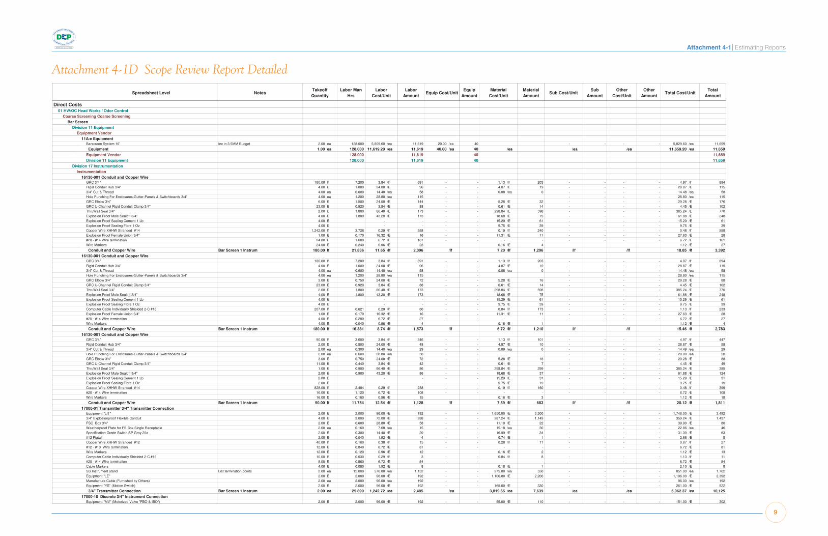
Attachment 4-1 Estimating Reports
9
Attachment 4-1D Scope Review Report DetailedSample Project Page 1
Scope Review Report - Detailed 5/15/2008 7:53 PM
Spreadsheet Level NotesTakeoffQuantity
Labor ManHrs
LaborCost/Unit
LaborAmount
Equip Cost/UnitEquip
AmountMaterial
Cost/UnitMaterialAmount
Sub Cost/UnitSub
AmountOther
Cost/UnitOther
AmountTotal Cost/Unit
TotalAmount
Direct Costs Direct Costs 01 HW/OC Head Works / Odor Control01 HW/OC Head Works / Odor Control
Coarse Screening Coarse ScreeningCoarse Screening Coarse ScreeningBar Screen Bar Screen
Division 11 EquipmentDivision 11 EquipmentEquipment Vendor Equipment Vendor
11A-e Equipment11A-e EquipmentBarscreen System 16' Inc in 3.5MM Budget 2.00 ea 128.000 5,809.60 /ea 11,619 20.00 /ea 40 - - - - 5,829.60 /ea 11,659
Equipment 1.00 ea 128.000 11,619.20 /ea 11,619 40.00 /ea 40 /ea /ea /ea 11,659.20 /ea 11,659Equipment Vendor 128.000 11,619 40 11,659Division 11 Equipment 128.000 11,619 40 11,659
Division 17 InstrumentationDivision 17 InstrumentationInstrumentation Instrumentation
16130-001 Conduit and Copper Wire16130-001 Conduit and Copper WireGRC 3/4" 180.00 lf 7.200 3.84 /lf 691 - - 1.13 /lf 203 - - - - 4.97 /lf 894Rigid Conduit Hub 3/4" 4.00 E 1.000 24.00 /E 96 - - 4.87 /E 19 - - - - 28.87 /E 1153/4" Cut & Thread 4.00 ea 0.600 14.40 /ea 58 - - 0.08 /ea 0 - - - - 14.48 /ea 58Hole Punching For Enclosures-Gutter-Panels & Switchboards 3/4" 4.00 ea 1.200 28.80 /ea 115 - - - - - - 28.80 /ea 115GRC Elbow 3/4" 6.00 E 1.500 24.00 /E 144 - - 5.28 /E 32 - - - - 29.28 /E 176GRC U-Channel Rigid Conduit Clamp 3/4" 23.00 E 0.920 3.84 /E 88 - - 0.61 /E 14 - - - - 4.45 /E 102ThruWall Seal 3/4" 2.00 E 1.800 86.40 /E 173 - - 298.84 /E 598 - - - - 385.24 /E 770Explosion Proof Male Sealoff 3/4" 4.00 E 1.800 43.20 /E 173 - - 18.68 /E 75 - - - - 61.88 /E 248Explosion Proof Sealing Cement 1 Lb 4.00 E - - - - 15.29 /E 61 - - - - 15.29 /E 61Explosion Proof Sealing Fibre 1 Oz 4.00 E - - - - 9.75 /E 39 - - - - 9.75 /E 39Copper Wire XHHW Stranded #14 1,242.00 lf 3.726 0.29 /lf 358 - - 0.19 /lf 240 - - - - 0.48 /lf 598Explosion Proof Female Union 3/4" 1.00 E 0.170 16.32 /E 16 - - 11.31 /E 11 - - - - 27.63 /E 28#20 - #14 Wire termination 24.00 E 1.680 6.72 /E 161 - - - - - - - - 6.72 /E 161Wire Markers 24.00 E 0.240 0.96 /E 23 0.16 /E 4 1.12 /E 27
Conduit and Copper Wire Bar Screen 1 Instrum 180.00 lf 21.836 11.65 /lf 2,096 /lf 7.20 /lf 1,296 /lf /lf 18.85 /lf 3,39216130-001 Conduit and Copper Wire16130-001 Conduit and Copper Wire
GRC 3/4" 180.00 lf 7.200 3.84 /lf 691 - - 1.13 /lf 203 - - - - 4.97 /lf 894Rigid Conduit Hub 3/4" 4.00 E 1.000 24.00 /E 96 - - 4.87 /E 19 - - - - 28.87 /E 1153/4" Cut & Thread 4.00 ea 0.600 14.40 /ea 58 - - 0.08 /ea 0 - - - - 14.48 /ea 58Hole Punching For Enclosures-Gutter-Panels & Switchboards 3/4" 4.00 ea 1.200 28.80 /ea 115 - - - - - - 28.80 /ea 115GRC Elbow 3/4" 3.00 E 0.750 24.00 /E 72 - - 5.28 /E 16 - - - - 29.28 /E 88GRC U-Channel Rigid Conduit Clamp 3/4" 23.00 E 0.920 3.84 /E 88 - - 0.61 /E 14 - - - - 4.45 /E 102ThruWall Seal 3/4" 2.00 E 1.800 86.40 /E 173 - - 298.84 /E 598 - - - - 385.24 /E 770Explosion Proof Male Sealoff 3/4" 4.00 E 1.800 43.20 /E 173 - - 18.68 /E 75 - - - - 61.88 /E 248Explosion Proof Sealing Cement 1 Lb 4.00 E - - - - 15.29 /E 61 - - - - 15.29 /E 61Explosion Proof Sealing Fibre 1 Oz 4.00 E - - - - 9.75 /E 39 - - - - 9.75 /E 39Computer Cable Individually Shielded 2-C #16 207.00 lf 0.621 0.29 /lf 60 - - 0.84 /lf 173 - - - - 1.13 /lf 233Explosion Proof Female Union 3/4" 1.00 E 0.170 16.32 /E 16 - - 11.31 /E 11 - - - - 27.63 /E 28#20 - #14 Wire termination 4.00 E 0.280 6.72 /E 27 - - - - - - - - 6.72 /E 27Wire Markers 4.00 E 0.040 0.96 /E 4 0.16 /E 1 1.12 /E 4
Conduit and Copper Wire Bar Screen 1 Instrum 180.00 lf 16.381 8.74 /lf 1,573 /lf 6.72 /lf 1,210 /lf /lf 15.46 /lf 2,78316130-001 Conduit and Copper Wire16130-001 Conduit and Copper Wire
GRC 3/4" 90.00 lf 3.600 3.84 /lf 346 - - 1.13 /lf 101 - - - - 4.97 /lf 447Rigid Conduit Hub 3/4" 2.00 E 0.500 24.00 /E 48 - - 4.87 /E 10 - - - - 28.87 /E 583/4" Cut & Thread 2.00 ea 0.300 14.40 /ea 29 - - 0.09 /ea 0 - - - - 14.49 /ea 29Hole Punching For Enclosures-Gutter-Panels & Switchboards 3/4" 2.00 ea 0.600 28.80 /ea 58 - - - - - - 28.80 /ea 58GRC Elbow 3/4" 3.00 E 0.750 24.00 /E 72 - - 5.28 /E 16 - - - - 29.28 /E 88GRC U-Channel Rigid Conduit Clamp 3/4" 11.00 E 0.440 3.84 /E 42 - - 0.61 /E 7 - - - - 4.45 /E 49ThruWall Seal 3/4" 1.00 E 0.900 86.40 /E 86 - - 298.84 /E 299 - - - - 385.24 /E 385Explosion Proof Male Sealoff 3/4" 2.00 E 0.900 43.20 /E 86 - - 18.68 /E 37 - - - - 61.88 /E 124Explosion Proof Sealing Cement 1 Lb 2.00 E - - - - 15.29 /E 31 - - - - 15.29 /E 31Explosion Proof Sealing Fibre 1 Oz 2.00 E - - - - 9.75 /E 19 - - - - 9.75 /E 19Copper Wire XHHW Stranded #14 828.00 lf 2.484 0.29 /lf 238 - - 0.19 /lf 160 - - - - 0.48 /lf 399#20 - #14 Wire termination 16.00 E 1.120 6.72 /E 108 - - - - - - - - 6.72 /E 108Wire Markers 16.00 E 0.160 0.96 /E 15 0.16 /E 3 1.12 /E 18
Conduit and Copper Wire Bar Screen 1 Instrum 90.00 lf 11.754 12.54 /lf 1,128 /lf 7.59 /lf 683 /lf /lf 20.12 /lf 1,81117000-01 Transmitter 3/4" Transmitter Connection 17000-01 Transmitter 3/4" Transmitter Connection
Equipment "LIT" 2.00 E 2.000 96.00 /E 192 - - 1,650.00 /E 3,300 - - - - 1,746.00 /E 3,4923/4" Explosionproof Flexible Conduit 4.00 E 3.000 72.00 /E 288 - - 287.24 /E 1,149 - - - - 359.24 /E 1,437FSC Box 3/4" 2.00 E 0.600 28.80 /E 58 - - 11.10 /E 22 - - - - 39.90 /E 80Weatherproof Plate for FS Box Single Receptacle 2.00 ea 0.160 7.68 /ea 15 - - 15.18 /ea 30 - - - - 22.86 /ea 46Specification Grade Switch SP Gray 20a 2.00 E 0.300 14.40 /E 29 - - 16.99 /E 34 - - - - 31.39 /E 63#12 Pigtail 2.00 E 0.040 1.92 /E 4 - - 0.74 /E 1 - - - - 2.66 /E 5Copper Wire XHHW Stranded #12 40.00 lf 0.160 0.38 /lf 15 - - 0.28 /lf 11 - - - - 0.67 /lf 27#12 - #10 Wire termination 12.00 E 0.840 6.72 /E 81 - - - - - - - - 6.72 /E 81Wire Markers 12.00 E 0.120 0.96 /E 12 0.16 /E 2 1.12 /E 13Computer Cable Individually Shielded 2-C #16 10.00 lf 0.030 0.29 /lf 3 - - 0.84 /lf 8 - - - - 1.13 /lf 11#20 - #14 Wire termination 8.00 E 0.560 6.72 /E 54 - - - - - - - - 6.72 /E 54Cable Markers 4.00 E 0.080 1.92 /E 8 0.18 /E 1 2.10 /E 8SS Instrument stand List termination points 2.00 ea 12.000 576.00 /ea 1,152 - - 275.00 /ea 550 - - - - 851.00 /ea 1,702Equipment "LE" 2.00 E 2.000 96.00 /E 192 - - 1,100.00 /E 2,200 - - - - 1,196.00 /E 2,392Manufacture Cable (Furnished by Others) 2.00 ea 2.000 96.00 /ea 192 - - - - - - - - 96.00 /ea 192Equipment "YS" (Motion Switch) 2.00 E 2.000 96.00 /E 192 - - 165.00 /E 330 - - - - 261.00 /E 522
3/4" Transmitter Connection Bar Screen 1 Instrum 2.00 ea 25.890 1,242.72 /ea 2,485 /ea 3,819.65 /ea 7,639 /ea /ea 5,062.37 /ea 10,12517000-10 Discrete 3/4" Instrument Connection 17000-10 Discrete 3/4" Instrument Connection
Equipment "MV" (Motorized Valve "FBO & IBO") 2.00 E 2.000 96.00 /E 192 - - 55.00 /E 110 - - - - 151.00 /E 302

10
Attachment 4-1 Estimating ReportsSample Project Page 8
Scope Review Report - Detailed 5/15/2008 7:53 PM
Spreadsheet Level NotesTakeoffQuantity
Labor ManHrs
LaborCost/Unit
LaborAmount
Equip Cost/UnitEquip
AmountMaterial
Cost/UnitMaterialAmount
Sub Cost/UnitSub
AmountOther
Cost/UnitOther
AmountTotal Cost/Unit
TotalAmount
Instrumentation Instrumentation 17000-10 Discrete 3/4" Instrument Connection 17000-10 Discrete 3/4" Instrument Connection
Equipment "MV" (Motorized Valve "FBO & IBO") 4.00 E 4.000 96.00 /E 384 - - 55.00 /E 220 - - - - 151.00 /E 6043/4" Explosionproof Flexible Conduit 4.00 E 3.000 72.00 /E 288 - - 287.24 /E 1,149 - - - - 359.24 /E 1,437Copper Wire XHHW Stranded #14 32.00 lf 0.096 0.29 /lf 9 - - 0.19 /lf 6 - - - - 0.48 /lf 15Wire Markers 16.00 E 0.160 0.96 /E 15 0.16 /E 3 1.12 /E 18#20 - #14 Wire termination 8.00 E 0.560 6.72 /E 54 - - - - - - - - 6.72 /E 54SS Instrument stand List termination points 4.00 ea 24.000 576.00 /ea 2,304 - - 275.00 /ea 1,100 - - - - 851.00 /ea 3,404Equipment "ZS" (Postions Switch "FBO" & "IBO") 8.00 E 12.000 144.00 /E 1,152 - - 55.00 /E 440 - - - - 199.00 /E 1,592Equipment "HS" (Hand Switch/Control Switch) 12.00 E 12.000 96.00 /E 1,152 - - 275.00 /E 3,300 - - - - 371.00 /E 4,452Equipment "ZL" 8.00 ea 4.000 48.00 /ea 384 - - 55.00 /ea 440 - - - - 103.00 /ea 824Heavy Duty One Unit Control Station NEMA 4 Open 4.00 ea 3.200 76.80 /ea 307 - - 85.80 /ea 343 - - - - 162.60 /ea 650Heavy Duty One Unit Control Station NEMA 4 Close 4.00 ea 3.200 76.80 /ea 307 - - 103.38 /ea 414 - - - - 180.18 /ea 721Heavy Duty One Unit Control Station NEMA 4 LOR 4.00 ea 4.000 96.00 /ea 384 - - 106.86 /ea 427 - - - - 202.86 /ea 811
3/4" Instrument Connection Influent Channel Ins 4.00 ea 70.216 1,685.19 /ea 6,741 /ea 1,960.46 /ea 7,842 /ea /ea 3,645.64 /ea 14,583Instrumentation 70.216 6,741 7,842 14,583Division 17 Instrumentation 70.216 6,741 7,842 14,583Sampling 267.256 24,627 145 3,516,016 300 3,541,088Flow Measurement Flow Measurement 561.423 51,911 190 3,557,483 300 3,609,884
General/Buildings General/Buildings Common Systems Common Systems
Division 03 ConcreteDivision 03 ConcreteFRP Concrete FRP Concrete
0301- Headworks Concrete Equipment0301- Headworks Concrete Equipment100-Ton Crawler Crane 16.00 wk 640.000 3,818.80 /wk 61,101 7,450.80 /wk 119,213 - - - - - - 11,269.60 /wk 180,314Concrete Vibrators 32.00 wk - - 150.00 /wk 4,800 - - - - - - 150.00 /wk 4,800Air Compressors 16.00 wk - - 566.00 /wk 9,056 - - - - - - 566.00 /wk 9,056Generators 16.00 wk - - 750.80 /wk 12,013 - - - - - - 750.80 /wk 12,013
Headworks Concrete Equipment Headworks Concrete Equipment 1.00 ls 640.000 61,100.80 /ls 61,101 145,081.60 /ls 145,082 /ls /ls /ls 206,182.40 /ls 206,182FRP Concrete 640.000 61,101 145,082 206,182Division 03 Concrete 640.000 61,101 145,082 206,182Common Systems 640.000 61,101 145,082 206,182
G/B-A-Substructure G/B-A-Substructure Division 03 ConcreteDivision 03 Concrete
FRP Concrete FRP Concrete 0322- Wall Concrete (Dimensional Takeoff)0322- Wall Concrete (Dimensional Takeoff)
4000 psi Concrete 61.67 cy - - - - 105.00 /cy 6,475 - - - - 105.00 /cy 6,475Pump Place Walls 61.67 cy 50.690 53.93 /cy 3,325 - - - - - - 10.00 /cy 617 63.93 /cy 3,942Job Built with Plyform 4-8' 2,664.00 sf 793.872 26.17 /sf 69,716 1.79 /sf 4,755 - - - - 27.96 /sf 74,471Strip & Oil Wall Forms 2,664.00 sf 45.288 1.07 /sf 2,845 - - - - - - - - 1.07 /sf 2,845Wall Bulkhead Forms 15.00 sf 6.450 37.76 /sf 566 2.10 /sf 32 - - - - 39.86 /sf 598Horizontal Wall Keyway 4" 397.00 lf 9.925 2.20 /lf 872 0.42 /lf 167 - - - - 2.62 /lf 1,038Vertical Wall Keyway 4" 345.00 lf 10.350 2.64 /lf 909 0.42 /lf 145 - - - - 3.06 /lf 1,054Waterstop 9" Bulb 409.00 lf 12.270 1.89 /lf 771 - - 7.88 /lf 3,221 - - - - 9.76 /lf 3,992Grind/Patch Walls 2,664.00 sf 66.600 1.57 /sf 4,184 - - 0.02 /sf 53 - - - - 1.59 /sf 4,238Liquid Curing Compounds 2,664.00 sf 7.992 0.19 /sf 502 - - 0.03 /sf 70 - - - - 0.22 /sf 572Finish- Top of Wall & Curb 277.50 sf 2.775 0.78 /sf 215 - - - - - - - - 0.78 /sf 215Wall Rebar 5.71 tn 114.100 1,356.60 /tn 7,739 - - 818.97 /tn 4,672 - - - - 2,175.57 /tn 12,412Sandblast CJ's 277.50 sf 13.875 3.14 /sf 872 0.25 /sf 69 - - - - 3.39 /sf 941Labor to Install Embedded Angle @ Top of Wall 222.00 lf 29.600 11.71 /lf 2,599 - - 1.58 /lf 350 - - - - 13.28 /lf 2,949
Wall Concrete (Dimensional Takeoff) Headworks Intermediate Channel & DrumScreen Area
61.67 cy 1,163.787 1,542.44 /cy 95,117 /cy 324.46 /cy 20,009 /cy 10.00 /cy 617 1,876.90 /cy 115,743
0330- S-O-G Concrete (Rectangular)0330- S-O-G Concrete (Rectangular)4000 psi Concrete 433.46 cy - - - - 105.00 /cy 45,513 - - - - 105.00 /cy 45,513Pump Place Slab on Grade 433.46 cy 270.911 41.00 /cy 17,773 - - - - - - 10.00 /cy 4,335 51.00 /cy 22,107Fine Grade SOG 7,802.25 sf 187.254 1.51 /sf 11,765 - - - - - - - - 1.51 /sf 11,765S.O.G. Edge Form > 1' 534.75 sf 117.645 19.32 /sf 10,331 1.31 /sf 702 - - - - 20.63 /sf 11,033S-O-G Const Joints > 1' 975.00 sf 282.750 25.47 /sf 24,831 1.31 /sf 1,280 - - - - 26.78 /sf 26,110Zip Strips 1/2" 650.00 lf 65.000 6.28 /lf 4,084 0.15 /lf 96 - - - - 6.43 /lf 4,180Sealant At Sealant Grooves 650.00 lf 8.125 1.10 /lf 714 - - 1.05 /lf 683 - - - - 2.15 /lf 1,396Strip & Oil SOG Form 1,509.75 sf 21.137 0.88 /sf 1,328 - - - - - - - - 0.88 /sf 1,328Waterstop 9" Bulb 650.00 lf 19.500 1.89 /lf 1,225 - - 7.88 /lf 5,119 - - - - 9.76 /lf 6,344Rebar/Mesh Support - Bricks 928.00 ea 2.320 0.17 /ea 157 - - 0.26 /ea 244 - - - - 0.43 /ea 401SOG Rebar 32.51 tn 406.363 847.88 /tn 27,564 - - 818.99 /tn 26,625 - - - - 1,666.86 /tn 54,188Finish- Hard Trowel 7,802.25 sf 163.847 1.63 /sf 12,709 - - 0.04 /sf 312 - - - - 1.67 /sf 13,021Liquid Curing Compounds 7,802.25 sf 23.407 0.19 /sf 1,471 - - 0.03 /sf 205 - - - - 0.22 /sf 1,675
S-O-G Concrete (Rectangular) Headworks Lower Level Floors 433.46 cy 1,568.258 262.89 /cy 113,951 /cy 186.35 /cy 80,776 /cy 10.00 /cy 4,335 459.24 /cy 199,0620330- S-O-G Concrete (Rectangular)0330- S-O-G Concrete (Rectangular)
4000 psi Concrete 175.00 cy - - - - 105.00 /cy 18,375 - - - - 105.00 /cy 18,375Pump Place Slab on Grade 175.00 cy 102.942 38.59 /cy 6,753 - - - - - - 10.00 /cy 1,750 48.59 /cy 8,503Fine Grade SOG 3,150.00 sf 75.600 1.51 /sf 4,750 - - - - - - - - 1.51 /sf 4,750S.O.G. Edge Form > 1' 375.00 sf 82.500 19.32 /sf 7,245 1.31 /sf 492 - - - - 20.63 /sf 7,737S-O-G Const Joints > 1' 337.50 sf 97.875 25.47 /sf 8,595 1.31 /sf 443 - - - - 26.78 /sf 9,038Zip Strips 1/2" 225.00 lf 21.177 5.91 /lf 1,331 0.15 /lf 33 - - - - 6.06 /lf 1,364Sealant At Sealant Grooves 225.00 lf 2.646 1.03 /lf 232 - - 1.05 /lf 236 - - - - 2.08 /lf 469Strip & Oil SOG Form 712.50 sf 9.975 0.88 /sf 627 - - - - - - - - 0.88 /sf 627Rebar/Mesh Support - Bricks 393.00 ea 0.924 0.16 /ea 63 - - 0.26 /ea 103 - - - - 0.42 /ea 166SOG Rebar 13.13 tn 154.412 798.00 /tn 10,474 - - 818.99 /tn 10,749 - - - - 1,616.99 /tn 21,223Finish- Hard Trowel 3,150.00 sf 66.150 1.63 /sf 5,131 - - 0.04 /sf 126 - - - - 1.67 /sf 5,257

Attachment 4-1 Estimating Reports
11
Sample Project Page 12Scope Review Report - Detailed 5/15/2008 7:53 PM
Spreadsheet Level NotesTakeoffQuantity
Labor ManHrs
LaborCost/Unit
LaborAmount
Equip Cost/UnitEquip
AmountMaterial
Cost/UnitMaterialAmount
Sub Cost/UnitSub
AmountOther
Cost/UnitOther
AmountTotal Cost/Unit
TotalAmount
PD System PD System 65.10 lf 89.000 124.10 /lf 8,079 /lf 138.94 /lf 9,045 /lf /lf 263.04 /lf 17,124Other Plumbing Syst. 89.000 8,079 9,045 17,124
Sanitary Waste Sanitary Waste 15A-h Floor Drainage15A-h Floor Drainage
SWgt Pipe Single Hub 6" 80.00 lf 20.000 22.69 /lf 1,816 - - 25.85 /lf 2,068 - - - - 48.55 /lf 3,884SWgt Pipe Single Hub 4" 60.00 lf 12.000 18.16 /lf 1,089 - - 13.69 /lf 821 - - - - 31.84 /lf 1,910SWgt 90 Ell 4 5.00 ea 3.000 54.47 /ea 272 - - 26.25 /ea 131 - - - - 80.72 /ea 404SWgt 90 Ell 6 4.00 ea 2.800 63.54 /ea 254 - - 45.70 /ea 183 - - - - 109.24 /ea 437SWgt 45 Ell 4 4.00 ea 2.560 58.10 /ea 232 - - 20.50 /ea 82 - - - - 78.60 /ea 314SWgt Wye 6 1.00 ea 1.400 127.09 /ea 127 - - 91.40 /ea 91 - - - - 218.49 /ea 218SWgt Wye 6x4 6.00 ea 8.400 127.09 /ea 763 - - 61.75 /ea 371 - - - - 188.84 /ea 1,133SWgt P Trap 4 4.00 ea 2.800 63.54 /ea 254 - - 43.15 /ea 173 - - - - 106.69 /ea 427Floor Drain 4" 4.00 ea 9.000 204.25 /ea 817 - - 125.00 /ea 500 - - - - 329.25 /ea 1,3176" Clean Outs 2.00 ea 2.000 90.78 /ea 182 5.00 /ea 10 70.00 /ea 140 - - - - 165.78 /ea 332
Floor Drainage Floor Drainage 140.00 lf 63.960 41.47 /lf 5,806 0.07 /lf 10 32.57 /lf 4,560 /lf /lf 74.11 /lf 10,376Sanitary Waste 63.960 5,806 10 4,560 10,376Division 15 Mechanical 839.630 76,217 1,610 114,076 60,000 251,903
Division 16 ElectricalDivision 16 ElectricalElect - Other Other Electrical ServicesElect - Other Other Electrical Services
16670-000 Lightning protection assembly16670-000 Lightning protection assemblyCopper Air Terminal 8.00 E 8.000 96.00 /E 768 - - 99.46 /E 796 - - - - 195.46 /E 1,564Copper Lightning protection cable 350.00 lf 12.250 3.36 /lf 1,176 - - 1.95 /lf 682 - - - - 5.31 /lf 1,858Lightning protection arrester 1.00 E 1.200 115.20 /E 115 - - 99.46 /E 99 - - - - 214.66 /E 21512" x 12" Rubber pad 124.67 E 12.467 9.60 /E 1,197 - - 0.99 /E 123 - - - - 10.59 /E 1,32012" x 12" Cement paver 8.00 E 8.000 96.00 /E 768 - - 99.46 /E 796 - - - - 195.46 /E 1,564GRC One Hole Steel Straps 1/2" 116.67 E 3.500 2.88 /E 336 - - 0.23 /E 27 - - - - 3.11 /E 363Sch 80 PVC Conduit 1" Overhead/Surface 210.00 lf 7.350 3.36 /lf 706 - - 0.77 /lf 161 - - - - 4.13 /lf 867GRC One Hole Steel Straps 1" 30.00 E 0.900 2.88 /E 86 - - 0.58 /E 17 - - - - 3.46 /E 104Cadwelds 6.00 ea 3.000 48.00 /ea 288 - - 12.17 /ea 73 - - - - 60.17 /ea 361Copper Lightning protection cable 252.00 lf 8.820 3.36 /lf 847 - - 1.95 /lf 491 - - - - 5.31 /lf 1,338Roof penetration and Roof Jack 6.00 ea 13.200 211.20 /ea 1,267 - - 16.50 /ea 99 - - - - 227.70 /ea 1,366Lightning Protection Certification 1.00 ls 4.000 384.00 /ls 384 - - - - 2,750.00 /ls 2,750 - - 3,134.00 /ls 3,134
Lightning protection assembly Lightning Protection 1.00 ea 82.687 7,937.92 /ea 7,938 /ea 3,365.21 /ea 3,365 2,750.00 /ea 2,750 /ea 14,053.13 /ea 14,053Elect - Other Other Electrical Services 82.687 7,938 3,365 2,750 14,053
Electrical Electrical 16151-110 Ground loop16151-110 Ground loop
Copper Wire Bare Stranded #4/0 450.00 lf 9.900 2.11 /lf 950 - - 4.56 /lf 2,054 - - - - 6.68 /lf 3,004Site Ditching 6" x 36" 450.00 lf 4.500 0.96 /lf 432 - - 1.93 /lf 866 - - - - 2.89 /lf 1,298Backfill per Cu/Yard 25.00 cy 12.500 48.00 /cy 1,200 - - 9.90 /cy 248 - - 57.90 /cy 1,448Detectable Warning Tape 450.00 lf - - - - 0.17 /lf 77 - - - - 0.17 /lf 77Ground Rod 3/4" x10' 8.00 E 6.400 76.80 /E 614 - - 9.50 /E 76 - - - - 86.30 /E 690Driving Stud 3/4" 8.00 E 0.400 4.80 /E 38 - - 4.93 /E 39 - - - - 9.73 /E 78Cadwelds 8.00 ea 4.000 48.00 /ea 384 - - 12.17 /ea 97 - - - - 60.17 /ea 481Sch 80 PVC Conduit 1" 200.00 lf 6.000 2.88 /lf 576 - - 0.77 /lf 154 - - - - 3.65 /lf 730Sch 80 PVC 90 Degree Elbow 1" 20.00 E 3.000 14.40 /E 288 - - 3.28 /E 66 - - - - 17.68 /E 354PVC Terminal Adaptor 1" 20.00 E 1.600 7.68 /E 154 - - 0.29 /E 6 - - - - 7.97 /E 1591 Pint PVC Cement 2.00 E 1.000 48.00 /E 96 - - 6.31 /E 13 - - - - 54.31 /E 109
Ground loop Building Ground 450.00 lf 49.300 10.52 /lf 4,733 /lf 7.66 /lf 3,447 0.55 /lf 248 /lf 18.73 /lf 8,428Electrical 49.300 4,733 3,447 248 8,428Division 16 Electrical 131.987 12,671 6,813 2,998 22,481
Division 17 InstrumentationDivision 17 InstrumentationInstrumentation Instrumentation
16001-011a Duct Bank - PVC Sch 40 or Sch 80 Conduit16001-011a Duct Bank - PVC Sch 40 or Sch 80 ConduitSch 40 PVC Conduit 1" 250.00 lf 7.500 2.88 /lf 720 - - 0.39 /lf 98 - - - - 3.27 /lf 818Plastic Coated Rigid Steel 90 Elbow 1" 2.00 E 0.700 33.60 /E 67 - - 10.86 /E 22 - - - - 44.46 /E 89PVC Female Adaptor 1" 2.00 E 0.160 7.68 /E 15 - - 0.33 /E 1 - - - - 8.01 /E 16Plastic Coated Rigid Steel Conduit 1" 20.00 lf 1.200 5.76 /lf 115 - - 3.36 /lf 67 - - - - 9.12 /lf 182Plastic Coated Rigid Steel Coupling 1" 4.00 E 0.280 6.72 /E 27 - - 3.47 /E 14 - - - - 10.19 /E 411" Cutting & Threading PVC Coated 2.00 ea 0.600 28.80 /ea 58 - - 0.22 /ea 0 - - - - 29.02 /ea 581 Pint PVC Cement 2.50 E 1.250 48.00 /E 120 - - 6.30 /E 16 - - - - 54.30 /E 136Tie Wire (50' roll) 2.50 ea 2.500 96.00 /ea 240 - - 8.80 /ea 22 - - - - 104.80 /ea 262#3 Re-bar 200.00 ea 2.000 0.96 /ea 192 - - 0.20 /ea 40 - - - - 1.16 /ea 232Copper Wire XHHW Stranded #14 500.00 lf 1.500 0.29 /lf 144 - - 0.19 /lf 97 - - - - 0.48 /lf 241#20 - #14 Wire termination 4.00 E 0.280 6.72 /E 27 - - - - - - - - 6.72 /E 27Wire Markers 4.00 E 0.040 0.96 /E 4 0.16 /E 1 1.12 /E 4
Duct Bank - PVC Sch 40 or Sch 80 Conduit Eye Wash 250.00 lf 18.010 6.92 /lf 1,729 /lf 1.51 /lf 377 /lf /lf 8.42 /lf 2,106Instrumentation 18.010 1,729 377 2,106Division 17 Instrumentation 18.010 1,729 377 2,106G/B-D-Services 989.627 90,617 1,610 121,265 62,998 276,489
G/B-G-Sitework G/B-G-Sitework Division 02 Division 02
Earthwork Earthwork 02B-200 Headworks Site Preparation02B-200 Headworks Site Preparation
Caterpillar CP-323C Vibratory Soil Compactor w/ Operator 8.00 hr 8.000 84.69 /hr 678 29.32 /hr 235 - - - - - - 114.01 /hr 912Caterpillar 938G Wheel Loader & Operator 16.00 hr 16.000 90.08 /hr 1,441 47.70 /hr 763 - - - - - - 137.78 /hr 2,204Dump Truck 14 cy 16.00 hr 16.000 74.72 /hr 1,196 48.53 /hr 776 - - - - - - 123.25 /hr 1,972Caterpillar 236 Skid Steer Loader w/ Operator 16.00 hr 16.000 84.69 /hr 1,355 26.31 /hr 421 - - - - - - 111.00 /hr 1,776General Laborer 32.00 hr 32.000 62.83 /hr 2,011 62.83 /hr 2,011Site Foreman 16.00 hr 16.000 95.47 /hr 1,528 14.64 /hr 234 - - - - - - 110.11 /hr 1,762

12
Attachment 4-1 Estimating Reports
Sample Project Page 109Scope Review Report - Detailed 5/15/2008 7:53 PM
Estimate Totals
Description Amount Totals Hours Rate Basis Percent of TotalLabor 30,949,175 394,139 hrs 21.67%
Material 35,656,998 24.97%Subcontract 5,802,535 4.06%
Equipment 2,904,813 84,108 hrs 2.03%Other 3,260,129 2.28%
78,573,650 78,573,650 55.02Small Tools & Supplies 1,547,459 5.00 % C 1.08%
Incidental Overtime Allowance 1,547,459 5.00 % C 1.08%Overtime Allowance - 48 hr/wk 2,321,188 7.50 % C 1.63%Overtime Allowance - 60 hr/wk 3,094,918 10.00 % C 2.17%Overtime Allowance - 70 hr/wk 4,642,376 15.00 % C 3.25%
Subcontractor OH&P 8,643,101 11.00 % C 6.05%Contractor Profit 15,714,730 20.00 % T 11.00%
Contractor Bond & Insurance 3,142,946 4.00 % T 2.20%Project Contingency 23,572,095 30.00 % T 16.51%
Total 142,799,922THIS IS A SAMPLE REPORT TO ILLUSTRATE REPORT LAYOUT ONLY. QUANTITIES, RATES, MARKUPS, ETC. SHOULD NOT BE USED FOR ESTIMATING PURPOSES. NOT ALL PAGES OF THE REPORT ARE INCLUDED IN THIS SAMPLE.

Attachment 4-1 Estimating Reports
13
Attachment 4-1E Labor Productivity Detail Report (Assembly) Sample Project Page 1Labor Productivity Detail Report (Assembly) 5/15/2008 7:05 PM
Assembly/DB Level 2
Spreadsheet LevelDB
Level3
Takeoff Quantity CrewLabor
Man Hrs
BaseProduc-
tivity
Produc-tivityAdj
EstimatedProductivity
LaborCost/Unit
LaborAmount
EquipCost/Unit
EquipAmount
Material ConvFactor
MatlWaste
% Material Quantity Material PriceMaterial
Cost/UnitMaterialAmount
Sub Cost/UnitSub
AmountOther
Cost/UnitOther
AmountTotal Cost/Unit Total Amount
02B-020 Chain Link Fencing02B-020 Chain Link Fencing2820.006 6' Chain Link Fence 2 2,000.00 lf - - - - No - - - - 13.00 26,000 - - 13.00 26,0002820.006 6' Fence Man Gate 4 4.00 ea - - - - No - - - - 175.00 700 - - 175.00 7002820.006 6' Fence Vehicle Gate 20' 20 1.00 ea - - - - No - - - - 880.00 880 - - 880.00 8802820.006 3 Strand Barb Wire @ Top Add 100 2,000.00 lf - - - - No - - - - 6.00 12,000 - - 6.00 12,000
Chain Link Fencing 2,000.00 lf 19.79 39,580 19.79 39,58002B-030 Traffic Control (Signs, Rails, Signals)02B-030 Traffic Control (Signs, Rails, Signals)
2892.100 Allowance for Site Signage (Traffic Control, Bldg ID, Etc.) 10 1.00 ls - - - - No - - - - 10,000.00 10,000 - - 10,000.00 10,000
Traffic Control (Signs, Rails, Signals) 1.00 ls 10,000.00 10,000 10,000.00 10,00002B-040 Grassed Areas02B-040 Grassed Areas
2900.990 Landscaping Allowance -sub 1.00 ls - - - - No - - - - 75,000.00 75,000 - - 75,000.00 75,000
Grassed Areas 75,000 75,00002B-120 Bituminous Paving-Small Areas02B-120 Bituminous Paving-Small Areas
2310.110 Rough Grade Areas 60 11,111.11 sy 02-Site Grade Rough 89 1,000.00 1,000.00 sy/cd 0.72 8,007 0.60 6,707 No - - - - - - - - 1.32 14,7142310.120 Fine Grade Small Pads 60 11,111.11 sy 02-Site Grade Fine 178 1,000.00 1,000.00 sy/cd 1.01 11,170 No 1.01 11,1702320.010 Gravel Base - Small Paving 70 3,703.70 cy 02-Site Fl Base 30 2,000.00 2,000.00 cy/cd 0.70 2,589 0.87 3,207 1.50 ton/cy Yes 30 7,222.22 ton 25.00 /ton 48.75 180,556 - - - - 50.32 186,3512740.120 Bituminous Base Course 3" 30 11,111.11 sy - - - - No - - - - 8.00 88,889 - - 8.00 88,8892740.120 Bituminous Binder Course 1" 110 11,111.11 sy - - - - No - - - - 5.00 55,556 - - 5.00 55,5562760.100 Painted Lines 6" Wide 6 5,000.00 lf - - - - No - - - - 0.45 2,250 - - 0.45 2,250
Bituminous Paving-Small Areas 11,111.11 sy 296 1.96 21,766 0.89 9,913 16.25 180,556 13.20 146,694 32.30 358,92902B-130 Concrete Sidewalks02B-130 Concrete Sidewalks
2895.100 Allowance for Misc Site Concrete 22 1.00 ls 06-Laborer ls/ch - - Yes 7 1.07 ls /ls 20,000.00 20,000 - - 20,000.00 20,000
Concrete Sidewalks 1.00 ls 20,000.00 20,000 20,000.00 20,00002B-200 Aeration Basins / MBR Excavation02B-200 Aeration Basins / MBR Excavation
1900.120 Cat Dozer D-8 d8 40.00 hr 01-Dozer D8 40 90.08 3,603 153.71 6,148 No - - - - - - - - 243.79 9,7521900.136 Cat Excavator 325 w/ Operator 325 80.00 hr 01-Excavator Cat 325 80 95.47 7,638 105.02 8,402 No - - - - - - - - 200.49 16,0392010.100 General Laborer 10 240.00 hr 02- General Laborer 240 62.83 15,079 No 62.83 15,0792010.100 Site Foreman 20 60.00 hr 02- General Foreman 60 95.47 5,728 14.64 878 No - - - - - - - - 110.11 6,6072010.100 Heavy Equipment Mechanic 30 60.00 hr 02- General Mechanic 60 89.83 5,390 No 89.83 5,390
Aeration Basins / MBR Excavation 3,500.00 bcy 480 10.70 37,438 4.41 15,428 15.11 52,86602B-200 Aeration Basins / MBR Backfill02B-200 Aeration Basins / MBR Backfill
1900.120 Cat Dozer D-8 w/ Operator d8 80.00 hr 01-Dozer D8 80 90.08 7,206 153.71 12,297 No - - - - - - - - 243.79 19,5031900.160 Caterpillar 825H Double Drum Soil Compactor w/ Operator 012 80.00 hr 01-Soil Comp 825H 80 84.69 6,775 142.02 11,362 No - - - - - - - - 226.71 18,1371900.210 Dump Truck 14 cy td14 160.00 hr 01-Truck Dump 14 160 74.72 11,955 48.53 7,765 No - - - - - - - - 123.25 19,7201900.220 Caterpillar 966G Wheel Loader & Operator 966G 80.00 hr 01-Wheel Loader 966G 80 90.08 7,206 80.62 6,450 No - - - - - - - - 170.70 13,6561900.240 Caterpillar 236 Skid Steer Loader w/ Operator 236 40.00 hr 01-Skid Steers 236 40 84.69 3,388 26.31 1,052 No - - - - - - - - 111.00 4,4402010.100 General Laborer 10 160.00 hr 02- General Laborer 160 62.83 10,053 No 62.83 10,0532010.100 Site Foreman 20 40.00 hr 02- General Foreman 40 95.47 3,819 14.64 586 No - - - - - - - - 110.11 4,4042010.100 Heavy Equipment Mechanic 30 40.00 hr 02- General Mechanic 40 89.83 3,593 No 89.83 3,593
Aeration Basins / MBR Backfill 3,500.00 ccy 680 15.43 53,996 11.29 39,511 26.72 93,50602B-200 Aeration Basins / MBR Subgrade Preparation02B-200 Aeration Basins / MBR Subgrade Preparation
1900.170 Caterpillar CP-663E Vibratory Soil Compactor w/ Operator 016 60.00 hr 01-Vib Roller 663E 60 84.69 5,081 63.70 3,822 No - - - - - - - - 148.39 8,9031900.220 Caterpillar 966G Wheel Loader & Operator 966G 30.00 hr 01-Wheel Loader 966G 30 90.08 2,702 80.62 2,419 No - - - - - - - - 170.70 5,1212010.100 General Laborer 10 120.00 hr 02- General Laborer 120 62.83 7,540 No 62.83 7,5402010.100 Site Foreman 20 60.00 hr 02- General Foreman 60 95.47 5,728 14.64 878 No - - - - - - - - 110.11 6,6072301.100 Purchase Type A: 3/4" Minus Granular Rock 05 1,450.00 CY - - - - 1.50 ton/CY No 2,175.00 ton 25.00 /ton 37.50 54,375 - - - - 37.50 54,375
Aeration Basins / MBR Subgrade Preparation 1,125.00 ccy 270 18.71 21,052 6.33 7,119 48.33 54,375 73.37 82,54602B-200 Headworks Site Preparation02B-200 Headworks Site Preparation
1900.170 Caterpillar CP-323C Vibratory Soil Compactor w/ Operator 010 8.00 hr 01-Vib Roller 323C 8 84.69 678 29.32 235 No - - - - - - - - 114.01 9121900.210 Dump Truck 14 cy td14 16.00 hr 01-Truck Dump 14 16 74.72 1,196 48.53 776 No - - - - - - - - 123.25 1,9721900.220 Caterpillar 938G Wheel Loader & Operator 938G 16.00 hr 01-Wheel Loader 938G 16 90.08 1,441 47.70 763 No - - - - - - - - 137.78 2,2041900.240 Caterpillar 236 Skid Steer Loader w/ Operator 236 16.00 hr 01-Skid Steers 236 16 84.69 1,355 26.31 421 No - - - - - - - - 111.00 1,7762010.100 General Laborer 10 32.00 hr 02- General Laborer 32 62.83 2,011 No 62.83 2,0112010.100 Site Foreman 20 16.00 hr 02- General Foreman 16 95.47 1,528 14.64 234 No - - - - - - - - 110.11 1,7622240.110 Maintenance of Pumps 60 350.00 day NYC Drilling Crew 1,051 0.33 0.33 day/ch 188.68 66,038 300.30 105,105 Yes 350.00 day 25.00 /day 25.00 8,750 - - - - 513.98 179,893
Headworks Site Preparation 1.00 ls 1,155 74,244.98 74,245 107,534.55 107,535 8,750.00 8,750 190,529.53 190,53002B-200 Headworks Odor Control Exterior Slab Site Preparation02B-200 Headworks Odor Control Exterior Slab Site Preparation
1900.220 Caterpillar 938G Wheel Loader & Operator 938G 8.00 hr 01-Wheel Loader 938G 8 90.08 721 47.70 382 No - - - - - - - - 137.78 1,1021900.240 Caterpillar 236 Skid Steer Loader w/ Operator 236 8.00 hr 01-Skid Steers 236 8 84.69 678 26.31 210 No - - - - - - - - 111.00 8882010.100 General Laborer *10 40.00 hr 02- General Laborer 40 62.83 2,513 No 62.83 2,5132240.110 Maintenance of Pumps 60 250.00 day NYC Drilling Crew 751 0.33 0.33 day/ch 188.68 47,170 300.30 75,075 Yes 250.00 day 25.00 /day 25.00 6,250 - - - - 513.98 128,495
Headworks Odor Control Exterior Slab SitePreparation
1.00 ls 807 51,081.03 51,081 75,667.16 75,667 6,250.00 6,250 132,998.19 132,998
02B-200 Reclaimed Water Pump Station Earthwork02B-200 Reclaimed Water Pump Station Earthwork1900.210 Dump Truck 14 cy td14 8.00 hr 01-Truck Dump 14 8 74.72 598 48.53 388 No - - - - - - - - 123.25 9861900.220 Caterpillar 966G Wheel Loader & Operator 966G 8.00 hr 01-Wheel Loader 966G 8 90.08 721 80.62 645 No - - - - - - - - 170.70 1,3661900.240 Caterpillar 236 Skid Steer Loader w/ Operator 236 8.00 hr 01-Skid Steers 236 8 84.69 678 26.31 210 No - - - - - - - - 111.00 8882010.100 General Laborer 10 32.00 hr 02- General Laborer 32 62.83 2,011 No 62.83 2,0112010.100 Site Foreman 20 16.00 hr 02- General Foreman 16 95.47 1,528 14.64 234 No - - - - - - - - 110.11 1,7622240.110 Maintenance of Pumps 60 25.00 day NYC Drilling Crew 75 0.33 0.33 day/ch 188.68 4,717 300.30 7,508 Yes 25.00 day 25.00 /day 25.00 625 - - - - 513.98 12,849
Reclaimed Water Pump Station Earthwork 1.00 ls 147 10,250.97 10,251 8,985.43 8,985 625.00 625 19,861.40 19,86102B-200 Duration Earthwork Equipment02B-200 Duration Earthwork Equipment
1900.120 Cat Dozer D-8 w/ Operator *d8 80.00 hr 01-Dozer D8 80 90.08 7,206 153.71 12,297 No - - - - - - - - 243.79 19,5031900.136 Cat Excavator 320 w/ Operator *320 80.00 hr 01-Excavator Cat 320 80 95.47 7,638 77.06 6,165 No - - - - - - - - 172.53 13,8021900.160 Caterpillar 815F Double Drum Soil Compactor w/ Operator *010 80.00 hr 01-Soil Comp 815F 80 84.69 6,775 106.54 8,523 No - - - - - - - - 191.23 15,2981900.210 Dump Truck 14 cy td14 40.00 hr 01-Truck Dump 14 40 74.72 2,989 48.53 1,941 No - - - - - - - - 123.25 4,9301900.220 Caterpillar 966G Wheel Loader & Operator *966G 80.00 hr 01-Wheel Loader 966G 80 90.08 7,206 80.62 6,450 No - - - - - - - - 170.70 13,6562010.100 General Laborer *10 160.00 hr 02- General Laborer 160 62.83 10,053 No 62.83 10,0532010.100 Site Foreman *20 80.00 hr 02- General Foreman 80 95.47 7,638 14.64 1,171 No - - - - - - - - 110.11 8,8092240.110 Maintenance of Pumps *60 5,700.00 day NYC Drilling Crew 17,117 0.33 0.33 day/ch 188.68 1,075,468 300.30 1,711,712 Yes 5,700.00 day 25.00 /day 25.00 142,500 - - - - 513.98 2,929,680

14
Attachment 4-1 Estimating ReportsSample Project Page 2
Labor Productivity Detail Report (Assembly) 5/15/2008 7:05 PM
Assembly/DB Level 2
Spreadsheet LevelDB
Level3
Takeoff Quantity CrewLabor
Man Hrs
BaseProduc-
tivity
Produc-tivityAdj
EstimatedProductivity
LaborCost/Unit
LaborAmount
EquipCost/Unit
EquipAmount
Material ConvFactor
MatlWaste
% Material Quantity Material PriceMaterial
Cost/UnitMaterialAmount
Sub Cost/UnitSub
AmountOther
Cost/UnitOther
AmountTotal Cost/Unit Total Amount
Duration Earthwork Equipment 5,700.00 bcy 17,717 197.36 1,124,973 306.71 1,748,259 25.00 142,500 529.08 3,015,73202B-240 Aeration Basins / MBR Well Point Dewatering System02B-240 Aeration Basins / MBR Well Point Dewatering System
2240.110 Set Well Points 10 74.00 ea NYC Drilling Crew 148 0.50 0.50 ea/ch 125.66 9,299 200.00 14,800 Yes 74.00 ea 350.00 /ea 350.00 25,900 675.66 49,9992240.110 Header Lines 12 1,100.00 lf - - No - - - - - - 5.00 5,500 5.00 5,5002240.110 Pumps and Equipment 50 180.00 day 02-Dewater Pumps - - 180.00 32,400 No - - - - - - - - 180.00 32,4002240.110 Maintenance of Pumps 60 180.00 day NYC Drilling Crew 541 0.33 0.33 day/ch 188.68 33,962 300.30 54,054 Yes 180.00 day 25.00 /day 25.00 4,500 513.98 92,516
Aeration Basins / MBR Well Point DewateringSystem
1.00 ls 689 43,261.00 43,261 101,254.05 101,254 30,400.00 30,400 5,500.00 5,500 180,415.05 180,415
0301- MBR / AerationConcrete Equipment0301- MBR / AerationConcrete Equipment3995.100 100-Ton Crawler Crane 6 12.00 wk 01-Crane Crawl 100 480 40.00 40.00 hr/wk 3,818.80 45,826 7,450.80 89,410 No - - - - - - - - 11,269.60 135,2353995.100 40-Ton Hyrdaulic Crane 10 40.00 wk 01-Crane Hydro 40 1,600 40.00 40.00 hr/wk 3,818.80 152,752 4,618.00 184,720 No - - - - - - - - 8,436.80 337,4723995.100 Concrete Buggies 50 52.00 wk 01-Concr Eqp-Buggies - - 200.00 10,400 No - - - - - - - - 200.00 10,4003995.100 Concrete Vibrators 52 104.00 wk 01-Concr Eqp-Vibr - - 150.00 15,600 No - - - - - - - - 150.00 15,6003995.100 Air Compressors 54 52.00 wk 01-Air Comp 185 - - 566.00 29,432 No - - - - - - - - 566.00 29,4323995.100 Generators 56 52.00 wk 01-Generator 45 - - 750.80 39,042 No - - - - - - - - 750.80 39,042
MBR / AerationConcrete Equipment 12.00 mon
2,080 16,548.13 198,578 30,716.93 368,603 47,265.07 567,181
0301- Headworks Concrete Equipment0301- Headworks Concrete Equipment3995.100 100-Ton Crawler Crane 6 16.00 wk 01-Crane Crawl 100 640 40.00 40.00 hr/wk 3,818.80 61,101 7,450.80 119,213 No - - - - - - - - 11,269.60 180,3143995.100 Concrete Vibrators 52 32.00 wk 01-Concr Eqp-Vibr - - 150.00 4,800 No - - - - - - - - 150.00 4,8003995.100 Air Compressors 54 16.00 wk 01-Air Comp 185 - - 566.00 9,056 No - - - - - - - - 566.00 9,0563995.100 Generators 56 16.00 wk 01-Generator 45 - - 750.80 12,013 No - - - - - - - - 750.80 12,013
Headworks Concrete Equipment 1.00 ls 640 61,100.80 61,101 145,081.60 145,082 206,182.40 206,1820301- Reject Water Storage Tank (7MG)0301- Reject Water Storage Tank (7MG)
3000.990 Reject Water Storage Tank (7MG) -sub 1.00 ls - - - - No - - - - 1,736,000.00 1,736,000 - - 1,736,000.00 1,736,000
Reject Water Storage Tank (7MG) 1.00 ls 1,736,000.00 1,736,000 1,736,000.00 1,736,0000301- Reclaimed Water Tank (10MG)0301- Reclaimed Water Tank (10MG)
3000.990 Reclaimed Water Tank (10MG) -sub 1.00 ls - - - - No - - - - 2,540,000.00 2,540,000 - - 2,540,000.00 2,540,000
Reclaimed Water Tank (10MG) 1.00 ls 2,540,000.00 2,540,000 2,540,000.00 2,540,0000302- Continuous Footings0302- Continuous Footings
2310.120 Hand Trim Footings 37 1,350.00 sf 02-Site Grade Fine 34 0.03 0.03 mh/sf 1.57 2,121 - - No - - - - - - - - 1.57 2,1213100.102 Continuous Footing Forms < 12" 2 900.00 sf 03-Conc Forming 126 0.14 0.14 mh/sf 12.30 11,065 Yes 900.00 sf 0.40 /sf 0.40 360 - - - - 12.70 11,4253100.310 Strip & Oil Footing Forms 14 900.00 sf 06-Laborer 9 0.01 0.01 mh/sf 0.63 565 - - No - - - - - - - - 0.63 5653210.104 Footing Rebar 202 3.75 tn 03-Conc Rebar 38 10.00 10.00 mh/tn 678.30 2,544 - - Yes 5 3.94 tn 780.00 /tn 819.10 3,072 - - - - 1,497.41 5,6153310.100 4000 psi Concrete 40 50.00 cy - - - - Yes 5 52.50 cy 100.00 /cy 105.00 5,250 - - - - 105.00 5,2503310.150 Truck Place Wall Footings 1 50.00 cy 03-Conc Placement 20 0.40 0.40 mh/cy 26.24 1,312 - - No - - - - - - - - 26.24 1,3123350.110 Finish- Float 4 1,350.00 sf 03-Conc Finishing 14 0.01 0.01 mh/sf 0.78 1,047 - - Yes 1,350.00 sf 0.01 /sf 0.01 14 - - - - 0.79 1,061
Continuous Footings 50.00 cy 240 373.08 18,654 173.90 8,695 546.98 27,3490303-1 Continuous Footings with Pier Footings0303-1 Continuous Footings with Pier Footings
3000.110 Form/Place/Finish Footings, incl rebar/cmu dowels 3 150.00 cy 03-Conc Forming 900 6.00 6.00 mh/cy 526.91 79,036 No 3 150.00 cy 250.00 /cy 250.00 37,500 7.00 1,050 - - 783.91 117,586
Continuous Footings with Pier Footings 150.00 cy 900 526.91 79,036 250.00 37,500 7.00 1,050 783.91 117,5860322- Wall Concrete (Dimensional Takeoff)0322- Wall Concrete (Dimensional Takeoff)
3100.180 Panel Form System 16'-> *b 17 46,834.00 sf 03-Conc Forming 8,196 0.18 0.18 mh/sf 15.37 719,752 Yes 5 49,175.70 sf 1.80 /sf 1.89 88,516 - - - - 17.26 808,2683100.180 Job Built with Plyform 0-4' *c 4 6,830.00 sf 03-Conc Forming 1,694 0.25 0.25 mh/sf 21.78 148,750 Yes 5 7,171.50 sf 1.60 /sf 1.68 11,474 - - - - 23.46 160,2243100.180 Job Built with Plyform 4-8' *c 8 10,548.00 sf 03-Conc Forming 3,143 0.30 0.30 mh/sf 26.17 276,039 Yes 5 11,075.40 sf 1.70 /sf 1.79 18,828 - - - - 27.96 294,8673100.180 Job Built with Plyform 8-12' *c 12 9,666.00 sf 03-Conc Forming 1,924 0.20 0.20 mh/sf 17.48 168,921 Yes 5 10,149.30 sf 1.80 /sf 1.89 18,269 - - - - 19.37 187,1903100.180 Job Built with Plyform 16'-> *c 17 38,188.00 sf 03-Conc Forming 6,683 0.18 0.18 mh/sf 15.37 586,879 Yes 5 40,097.40 sf 2.00 /sf 2.10 80,195 - - - - 17.47 667,0743100.310 Strip & Oil Wall Forms *22 112,066.00 sf 06-Laborer 1,905 0.02 0.02 mh/sf 1.07 119,699 - - No - - - - - - - - 1.07 119,6993150.192 Wall Bulkhead Forms *2 3,572.00 sf 03-Conc Forming 1,536 0.43 0.43 mh/sf 37.76 134,885 Yes 5 3,750.60 sf 2.00 /sf 2.10 7,501 - - - - 39.86 142,3863150.198 Labor to Install Embedded Angle @ Top of Wall *12 1,049.00 lf 03-Conc Forming 140 7.50 7.50 lf/mh 11.71 12,283 - - Yes 5 1,101.45 lf 1.50 /lf 1.58 1,652 - - - - 13.28 13,9353150.620 Keyway 4" *4 2,619.00 lf 03-Conc Forming 52 0.02 0.02 mh/lf 1.76 4,600 Yes 5 2,749.95 lf 0.40 /lf 0.42 1,100 - - - - 2.18 5,7003150.620 Horizontal Wall Keyway 4" *24 4,495.00 lf 03-Conc Forming 112 0.03 0.03 mh/lf 2.20 9,869 Yes 5 4,719.75 lf 0.40 /lf 0.42 1,888 - - - - 2.62 11,7563150.620 Vertical Wall Keyway 4" *34 1,625.00 lf 03-Conc Forming 49 0.03 0.03 mh/lf 2.64 4,281 Yes 5 1,706.25 lf 0.40 /lf 0.42 683 - - - - 3.06 4,9643210.104 Wall Rebar *210 343.78 tn 03-Conc Rebar 6,876 20.00 20.00 mh/tn 1,356.60 466,372 - - Yes 5 360.97 tn 780.00 /tn 819.00 281,555 - - - - 2,175.60 747,9273310.100 4000 psi Concrete *40 3,744.82 cy - - - - Yes 5 3,932.06 cy 100.00 /cy 105.00 393,206 - - - - 105.00 393,2063310.260 Truck Place Walls 1 33.33 cy 03-Conc Placement 20 0.60 0.60 mh/cy 39.36 1,312 - - No - - - - - - - - 39.36 1,3123310.260 Pump Place Walls *3 3,711.48 cy 03-Conc Placement 3,051 0.82 0.82 mh/cy 53.93 200,144 - - No - - - - - - 10.00 37,115 63.93 237,2593350.110 Finish- Top of Wall & Curb *20 6,692.50 sf 03-Conc Finishing 67 0.01 0.01 mh/sf 0.78 5,191 - - No - - - - - - - - 0.78 5,1913350.130 Grind/Patch Walls *2 112,066.00 sf 06-Laborer 2,802 0.03 0.03 mh/sf 1.57 176,028 - - Yes 112,066.00 sf 0.02 /sf 0.02 2,241 - - - - 1.59 178,2693350.140 Rub Walls 2 3,393.00 sf 06-Laborer 254 0.08 0.08 mh/sf 4.71 15,989 - - Yes 3,393.00 sf 0.20 /sf 0.20 679 - - - - 4.91 16,6673350.150 Sandblast CJ's *3 6,692.50 sf 06-Laborer 335 0.05 0.05 mh/sf 3.14 21,024 Yes 6,692.50 sf 0.25 /sf 0.25 1,673 - - - - 3.39 22,6983390.170 Liquid Curing Compounds *2 112,066.00 sf 06-Laborer 336 0.00 0.00 mh/sf 0.19 21,123 - - Yes 5 117,669.30 sf 0.03 /sf 0.03 2,942 - - - - 0.22 24,0653510.610 Waterstop 6" Bulb *106 4,529.00 lf 06-Laborer 91 0.02 0.02 mh/lf 1.26 5,691 - - Yes 5 4,755.45 lf 6.25 /lf 6.56 29,722 - - - - 7.82 35,4133510.610 Waterstop 9" Bulb *109 1,209.00 lf 06-Laborer 36 0.03 0.03 mh/lf 1.89 2,279 - - Yes 5 1,269.45 lf 7.50 /lf 7.88 9,521 - - - - 9.76 11,800
Wall Concrete (Dimensional Takeoff) 3,744.82 cy 39,301 828.11 3,101,110 254.12 951,644 9.91 37,115 1,092.14 4,089,8680322- Wall Concrete (Dimensional Takeoff)0322- Wall Concrete (Dimensional Takeoff)
7110.100 Sprayed On Bituminous Damproofing 15 15,000.00 sf 07-Insul\Waterprof 225 0.02 0.02 mh/sf 1.08 16,252 - - Yes 7 16,050.00 sf 0.60 /sf 0.64 9,630 - - - - 1.73 25,882
Wall Concrete (Dimensional Takeoff) 15,000.00 sf 225 1.08 16,252 0.64 9,630 1.73 25,8820326- Rectangle Column Concrete0326- Rectangle Column Concrete
3100.110 Form Rectangle Columns 16 -20' 20 5,760.00 sf 03-Conc Forming 1,220 0.21 0.21 mh/sf 18.60 107,115 Yes 5 6,048.00 sf 1.50 /sf 1.58 9,072 - - - - 20.17 116,1873100.310 Strip & Oil Column Forms 4 5,760.00 sf 06-Laborer 68 0.01 0.01 mh/sf 0.74 4,256 - - No - - - - - - - - 0.74 4,2563150.625 Chamfer 1" 10 2,880.00 lf 03-Conc Forming 50 0.02 0.02 mh/lf 1.54 4,434 Yes 5 3,024.00 lf 0.20 /lf 0.21 605 - - - - 1.75 5,0383210.104 Column Rebar 206 9.33 tn 03-Conc Rebar 110 11.76 11.76 mh/tn 798.00 7,449 - - Yes 5 9.80 tn 780.00 /tn 819.03 7,645 - - - - 1,617.03 15,0933310.100 4000 psi Concrete 40 106.67 cy - - - - Yes 5 112.00 cy 100.00 /cy 105.00 11,200 - - - - 105.00 11,2003310.270 Pump Place Piers & Columns 3 106.67 cy 03-Conc Placement 69 0.65 0.65 mh/cy 42.45 4,528 - - No - - - - - - 10.00 1,067 52.45 5,5953350.130 Grind/Patch Columns 4 5,760.00 sf 06-Laborer 173 0.03 0.03 mh/sf 1.89 10,857 - - Yes 5,760.00 sf 0.02 /sf 0.02 115 - - - - 1.91 10,9723390.170 Liquid Curing Compounds 2 5,760.00 sf 06-Laborer 17 0.00 0.00 mh/sf 0.19 1,086 - - Yes 5 6,048.00 sf 0.03 /sf 0.03 151 - - - - 0.22 1,237
Rectangle Column Concrete 106.67 cy 1,707 1,309.92 139,724 269.89 28,788 10.00 1,067 1,589.81 169,5780330- Upper Floor Structural0330- Upper Floor Structural
3000.135 Topping Slab, 2" thick 4 110.00 cy 03-Conc Forming 1,100 10.00 10.00 mh/cy 878.18 96,600 - - No 110.00 cy 250.00 /cy 250.00 27,500 20.00 2,200 - - 1,148.18 126,3003410.130 PC Hollow Core Planks 8", grouted, w/embeds 80 14,000.00 sf 03-Conc Precast 350 0.03 0.03 mh/sf 2.39 33,411 0.98 13,691 Yes 14,000.00 sf 11.00 /sf 11.00 154,000 - - - - 14.36 201,102

Attachment 4-1 Estimating Reports
15
Sample Project Page 8Labor Productivity Detail Report (Assembly) 5/15/2008 7:05 PM
Assembly/DB Level 2
Spreadsheet LevelDB
Level3
Takeoff Quantity CrewLabor
Man Hrs
BaseProduc-
tivity
Produc-tivityAdj
EstimatedProductivity
LaborCost/Unit
LaborAmount
EquipCost/Unit
EquipAmount
Material ConvFactor
MatlWaste
% Material Quantity Material PriceMaterial
Cost/UnitMaterialAmount
Sub Cost/UnitSub
AmountOther
Cost/UnitOther
AmountTotal Cost/Unit Total Amount
15A-c Grit System15A-c Grit System15203.002 DI Flg x Flg Pipe 4" x 15' CL-53 415 2.00 ea 15-PipeCrew 8 4.00 4.00 mh/ea 363.10 726 - - 233.00 lb/ea No 466.00 lb 2.60 /lb 605.80 1,212 - - - - 968.90 1,93815203.002 DI Flg x Flg Pipe 4" x 18' CL-53 418 2.00 ea 15-PipeCrew 8 4.00 4.00 mh/ea 363.10 726 - - 274.40 lb/ea No 548.80 lb 2.60 /lb 713.44 1,427 - - - - 1,076.54 2,15315203.002 DI Flg x Flg Pipe 6" x 1' CL-53 601 8.00 ea 15-PipeCrew 24 3.00 3.00 mh/ea 272.33 2,179 - - 55.40 lb/ea No 443.20 lb 2.60 /lb 144.04 1,152 - - - - 416.37 3,33115203.002 DI Flg x Flg Pipe 6" x 3' CL-53 603 4.00 ea 15-PipeCrew 12 3.00 3.00 mh/ea 272.33 1,089 - - 98.20 lb/ea No 392.80 lb 2.60 /lb 255.32 1,021 - - - - 527.65 2,11115203.002 DI Flg x Flg Pipe 6" x 4' CL-53 604 4.00 ea 15-PipeCrew 12 3.00 3.00 mh/ea 272.33 1,089 - - 119.60 lb/ea No 478.40 lb 2.60 /lb 310.96 1,244 - - - - 583.29 2,33315203.002 DI Flg x Flg Pipe 6" x 7' CL-53 607 2.00 ea 15-PipeCrew 14 7.00 7.00 mh/ea 635.43 1,271 - - 183.80 lb/ea No 367.60 lb 2.60 /lb 477.88 956 - - - - 1,113.31 2,22715203.002 DI Flg x Flg Pipe 6" x 18' CL-53 618 2.00 ea 15-PipeCrew 14 7.00 7.00 mh/ea 635.43 1,271 - - 419.20 lb/ea No 838.40 lb 2.60 /lb 1,089.92 2,180 - - - - 1,725.35 3,45115203.014 DI Flanged 90 SR ell 4" 4 5.00 ea 15-PipeCrew 13 2.50 2.50 mh/ea 226.94 1,135 - - 50.00 lb/ea No 250.00 lb 2.90 /lb 145.00 725 - - - - 371.94 1,86015203.014 DI Flanged 90 SR ell 6" 6 6.00 ea 15-PipeCrew 18 3.00 3.00 mh/ea 272.33 1,634 - - 80.00 lb/ea No 480.00 lb 2.90 /lb 232.00 1,392 - - - - 504.33 3,02615203.030 DI Flanged Con Red 6x4" 604 2.00 ea 15-PipeCrew 6 3.00 3.00 mh/ea 272.33 545 - - 45.00 lb/ea No 90.00 lb 2.60 /lb 117.00 234 - - - - 389.33 77915203.065 DI Flg x Flg Wall Pipe 4" x 2' CL53 582 2.00 ea 15-PipeCrew 8 4.00 4.00 mh/ea 363.10 726 - - No 2.00 ea 348.40 /ea 348.40 697 - - - - 711.50 1,42315203.065 DI Flg x Flg Wall Pipe 6" x 2' CL53 1136 3.00 ea 15-PipeCrew 15 5.00 5.00 mh/ea 453.88 1,362 - - No 3.00 ea 403.00 /ea 403.00 1,209 - - - - 856.88 2,57115203.091 DI Flat Blind Flange 4" 4 2.00 ea 15-PipeCrew 5 2.50 2.50 mh/ea 226.94 454 - - 10.00 lb/ea No 20.00 lb 2.60 /lb 26.00 52 - - - - 252.94 50615241.211 Dresser Flanged Coupling Adapter 4" 20 3.00 ea 15-PipeCrew 4 1.20 1.20 mh/ea 108.93 327 - - No 3.00 ea 67.00 /ea 67.00 201 - - - - 175.93 52815241.211 Dresser Flanged Coupling Adapter 6" 25 3.00 ea 15-PipeCrew 5 1.50 1.50 mh/ea 136.16 408 - - No 3.00 ea 85.00 /ea 85.00 255 - - - - 221.16 663
Grit System 217.35 lf 322 134.65 29,266 0.41 90 117.70 25,582 252.76 54,93815A-c PD System15A-c PD System
15120.002 Bolt, Nut & Gasket Set ANSI C110/AWWA A21.10-150# 8 a 80 15.00 ea 15-PipeCrew 15 1.00 1.00 mh/ea 90.78 1,362 - - No 15.00 ea 49.40 /ea 49.40 741 - - - - 140.18 2,10315203.002 DI Flg x Flg Pipe 8" x 4' CL-53 804 2.00 ea 15-PipeCrew 8 4.00 4.00 mh/ea 363.10 726 - - 174.40 lb/ea No 348.80 lb 2.60 /lb 453.44 907 - - - - 816.54 1,63315203.002 DI Flg x Flg Pipe 8" x 6' CL-53 806 2.00 ea 15-PipeCrew 8 4.00 4.00 mh/ea 363.10 726 - - 234.60 lb/ea No 469.20 lb 2.60 /lb 609.96 1,220 - - - - 973.06 1,94615203.002 DI Flg x Flg Pipe 8" x 8' CL-53 808 3.00 ea 15-PipeCrew 24 8.00 8.00 mh/ea 726.20 2,179 - - 294.80 lb/ea No 884.40 lb 2.60 /lb 766.48 2,299 - - - - 1,492.68 4,47815203.002 DI Flg x Flg Pipe 8" x 18' CL-53 818 1.00 ea 15-PipeCrew 8 8.00 8.00 mh/ea 726.20 726 - - 595.80 lb/ea No 595.80 lb 2.60 /lb 1,549.08 1,549 - - - - 2,275.28 2,27515203.014 DI Flanged 90 SR ell 8" 8 4.00 ea 15-PipeCrew 16 4.00 4.00 mh/ea 363.10 1,452 - - 140.00 lb/ea No 560.00 lb 2.90 /lb 406.00 1,624 - - - - 769.10 3,07615203.065 DI Flg x Flg Wall Pipe 8" x 2' CL53 1690 1.00 ea 15-PipeCrew 6 6.00 6.00 mh/ea 544.65 545 - - No 1.00 ea 496.60 /ea 496.60 497 - - - - 1,041.25 1,04115203.091 DI Flat Blind Flange 8" 8 1.00 ea 15-PipeCrew 4 4.00 4.00 mh/ea 363.10 363 - - 80.00 lb/ea No 80.00 lb 2.60 /lb 208.00 208 - - - - 571.10 571
PD System 65.10 lf 89 124.10 8,079 138.94 9,045 263.04 17,12415A-c Scum System-Glass Lined15A-c Scum System-Glass Lined
11295.110 Flg Plug Valve 6", V-30-852,862,854,864,865 +3 6 8.00 ea 15-PipeCrew 40 5.00 5.00 mh/ea 453.88 3,631 7.50 60 No 8.00 ea 500.00 /ea 500.00 4,000 - - - - 961.38 7,69111295.120 Swing Check Valve 6",V-30-813/853 06 2.00 ea 15-PipeCrew 10 5.00 5.00 mh/ea 453.88 908 5.00 10 No 2.00 ea 1,800.00 /ea 1,800.00 3,600 - - - - 2,258.88 4,51815000.001 Pressure Gauge & Switch Assembly 005 3.00 ea 15-PipeCrew 24 7.96 7.96 mh/ea 722.57 2,168 - - No 3.00 ea 235.87 /ea 235.87 708 - - 958.44 2,87515000.001 Air/Vacuum Release Assembly- 3" & Smaller 010 2.00 ea 15-PipeCrew 40 20.19 20.19 mh/ea 1,832.75 3,665 - - No 2.00 ea 1,427.94 /ea 1,427.94 2,856 - - - - 3,260.69 6,52115120.002 Bolt, Nut & Gasket Set ANSI C110/AWWA A21.10-150# 4 a 40 3.00 ea 15-PipeCrew 3 0.85 0.85 mh/ea 77.16 231 - - No 3.00 ea 27.84 /ea 27.84 84 - - - - 105.00 31515120.002 Bolt, Nut & Gasket Set ANSI C110/AWWA A21.10-150# 6 a 60 30.00 ea 15-PipeCrew 30 1.00 1.00 mh/ea 90.78 2,723 - - No 30.00 ea 35.69 /ea 35.69 1,071 - - - - 126.47 3,79415203.002 DI Flg x Flg Pipe 4" x 2' CL-53 402 7.00 ea 15-PipeCrew 18 2.50 2.50 mh/ea 226.94 1,589 - - 53.60 lb/ea No 375.20 lb 2.60 /lb 139.36 976 - - - - 366.30 2,56415203.002 DI Flg x Flg Pipe 6" x 2' CL-53 602 2.00 ea 15-PipeCrew 6 3.00 3.00 mh/ea 272.33 545 - - 76.80 lb/ea No 153.60 lb 2.60 /lb 199.68 399 - - - - 472.01 94415203.002 DI Flg x Flg Pipe 6" x 4' CL-53 604 2.00 ea 15-PipeCrew 6 3.00 3.00 mh/ea 272.33 545 - - 119.60 lb/ea No 239.20 lb 2.60 /lb 310.96 622 - - - - 583.29 1,16715203.002 DI Flg x Flg Pipe 6" x 6' CL-53 606 2.00 ea 15-PipeCrew 6 3.00 3.00 mh/ea 272.33 545 - - 162.40 lb/ea No 324.80 lb 2.60 /lb 422.24 844 - - - - 694.57 1,38915203.002 DI Flg x Flg Pipe 6" x 8' CL-53 608 2.00 ea 15-PipeCrew 14 7.00 7.00 mh/ea 635.43 1,271 - - 205.20 lb/ea No 410.40 lb 2.60 /lb 533.52 1,067 - - - - 1,168.95 2,33815203.002 DI Flg x Flg Pipe 6" x 12' CL-53 612 2.00 ea 15-PipeCrew 14 7.00 7.00 mh/ea 635.43 1,271 - - 290.80 lb/ea No 581.60 lb 2.60 /lb 756.08 1,512 - - - - 1,391.51 2,78315203.014 DI Flanged 90 SR ell 6" 6 9.00 ea 15-PipeCrew 27 3.00 3.00 mh/ea 272.33 2,451 - - 80.00 lb/ea No 720.00 lb 2.90 /lb 232.00 2,088 - - - - 504.33 4,53915203.030 DI Flanged Con Red 6x4" 604 2.00 ea 15-PipeCrew 6 3.00 3.00 mh/ea 272.33 545 - - 45.00 lb/ea No 90.00 lb 2.60 /lb 117.00 234 - - - - 389.33 77915203.065 DI Flg x Flg Wall Pipe 6" x 2' CL53 1136 5.00 ea 15-PipeCrew 25 5.00 5.00 mh/ea 453.88 2,269 - - No 5.00 ea 403.00 /ea 403.00 2,015 - - - - 856.88 4,28415241.211 Dresser Flanged Coupling Adapter 4" 20 2.00 ea 15-PipeCrew 2 1.20 1.20 mh/ea 108.93 218 - - No 2.00 ea 67.00 /ea 67.00 134 - - - - 175.93 352
Scum System-Glass Lined 71.40 lf 271 344.17 24,574 0.98 70 311.05 22,209 656.20 46,85315A-c Activate Sludge Basins 1 & 215A-c Activate Sludge Basins 1 & 2
11295.120 Swing Check Valve 20", CSRWRF-V-40-132,133,232 , 233 20 4.00 ea 15-PipeCrew 64 16.00 16.00 mh/ea 1,452.40 5,810 7.50 30 No 4.00 ea 9,500.00 /ea 9,500.00 38,000 - - - - 10,959.90 43,84011295.120 Swing Check Valve 24", CSRWRF-V-40-151,152,251,252 24 4.00 ea 15-PipeCrew 76 19.00 19.00 mh/ea 1,724.73 6,899 7.50 30 No 4.00 ea 14,500.00 /ea 14,500.00 58,000 - - - - 16,232.23 64,92915060.036 Floor Stand Assembly-Galv with U-bolt 20 x 2' 607 16.00 ea 15-PipeCrew 144 9.00 9.00 mh/ea 816.98 13,072 2.50 40 No 16.00 ea 635.00 /ea 635.00 10,160 - - - - 1,454.48 23,27215060.036 Floor Stand Assembly-Galv with U-bolt 24 x 2' 623 40.00 ea 15-PipeCrew 440 11.00 11.00 mh/ea 998.53 39,941 2.50 100 No 40.00 ea 700.00 /ea 700.00 28,000 - - - - 1,701.03 68,04115120.002 Bolt, Nut & Gasket Set ANSI C110/AWWA A21.10-150# 20 a200 31.00 ea 15-PipeCrew 127 4.10 4.10 mh/ea 372.18 11,538 - - No 31.00 ea 251.74 /ea 251.74 7,804 - - - - 623.92 19,34115120.002 Bolt, Nut & Gasket Set ANSI C110/AWWA A21.10-150# 24 a201 43.00 ea 15-PipeCrew 200 4.65 4.65 mh/ea 422.10 18,150 - - No 43.00 ea 350.55 /ea 350.55 15,074 - - - - 772.65 33,22415203.002 DI Flg x Flg Pipe 20" x 4' CL-53 2004 8.00 ea 15-PipeCrew 80 10.00 10.00 mh/ea 907.75 7,262 - - 590.00 lb/ea No 4,720.00 lb 2.60 /lb 1,534.00 12,272 - - - - 2,441.75 19,53415203.002 DI Flg x Flg Pipe 20" x 8' CL-53 2008 2.00 ea 15-PipeCrew 30 15.00 15.00 mh/ea 1,361.63 2,723 - - 956.00 lb/ea No 1,912.00 lb 2.60 /lb 2,485.60 4,971 - - - - 3,847.23 7,69415203.002 DI Flg x Flg Pipe 20" x 18' CL-53 2018 8.00 ea 15-PipeCrew 120 15.00 15.00 mh/ea 1,361.63 10,893 - - 1,871.00 lb/ea No 14,968.00 lb 2.60 /lb 4,864.60 38,917 - - - - 6,226.23 49,81015203.002 DI Flg x Flg Pipe 24" x 4' CL-53 2404 8.00 ea 15-PipeCrew 88 11.00 11.00 mh/ea 998.53 7,988 - - 767.60 lb/ea No 6,140.80 lb 2.60 /lb 1,995.76 15,966 - - - - 2,994.29 23,95415203.002 DI Flg x Flg Pipe 24" x 8' CL-53 2408 2.00 ea 15-PipeCrew 32 16.00 16.00 mh/ea 1,452.40 2,905 - - 1,225.20 lb/ea No 2,450.40 lb 2.60 /lb 3,185.52 6,371 - - - - 4,637.92 9,27615203.002 DI Flg x Flg Pipe 24" x 18' CL-53 2418 20.00 ea 15-PipeCrew 320 16.00 16.00 mh/ea 1,452.40 29,048 - - 2,369.20 lb/ea No 47,384.00 lb 2.60 /lb 6,159.92 123,198 - - - - 7,612.32 152,24615203.014 DI Flanged 90 SR ell 20" 20 4.00 ea 15-PipeCrew 44 11.00 11.00 mh/ea 998.53 3,994 - - 810.00 lb/ea No 3,240.00 lb 2.90 /lb 2,349.00 9,396 - - - - 3,347.53 13,39015203.014 DI Flanged 90 SR ell 24" 24 4.00 ea 15-PipeCrew 48 12.00 12.00 mh/ea 1,089.30 4,357 - - 1,240.00 lb/ea No 4,960.00 lb 2.90 /lb 3,596.00 14,384 - - - - 4,685.30 18,74115203.065 DI Flg x Flg Wall Pipe 20" x 2' CL53 5014 2.00 ea 15-PipeCrew 22 11.00 11.00 mh/ea 998.53 1,997 - - No 2.00 ea 1,267.50 /ea 1,267.50 2,535 - - - - 2,266.03 4,53215203.065 DI Flg x Flg Wall Pipe 24" x 2' CL53 5568 2.00 ea 15-PipeCrew 24 12.00 12.00 mh/ea 1,089.30 2,179 - - No 2.00 ea 1,652.30 /ea 1,652.30 3,305 - - - - 2,741.60 5,483
Activate Sludge Basins 1 & 2 630.00 lf 1,859 267.87 168,755 0.32 200 616.43 388,353 884.62 557,30815A-c Sub Pmps Alternate B15A-c Sub Pmps Alternate B
11210.150 Submersible Pump w/ Rails & Ell Ftg 76-100 hp 55 6.00 ea 15-PipeCrew 336 56.00 56.00 mh/ea 5,083.40 30,500 15.00 90 Yes 6.00 ea 11,000.00 /ea 11,000.00 66,000 - - - - 16,098.40 96,59011286.001 Gate Valve - Lvr/HW - 10" 25 6.00 ea 15-PipeCrew 48 8.00 8.00 mh/ea 726.20 4,357 5.00 30 No 6.00 ea 2,100.00 /ea 2,100.00 12,600 - - - - 2,831.20 16,98711295.120 Swing Check Valve 10" 10 6.00 ea 15-PipeCrew 48 8.00 8.00 mh/ea 726.20 4,357 5.00 30 No 6.00 ea 2,800.00 /ea 2,800.00 16,800 - - - - 3,531.20 21,18715060.036 Floor Stand Assembly-Galv with U-bolt 10 x 2' 527 42.00 ea 15-PipeCrew 294 7.00 7.00 mh/ea 635.43 26,688 5.00 210 No 42.00 ea 412.00 /ea 412.00 17,304 - - - - 1,052.43 44,20215120.002 Bolt, Nut & Gasket Set ANSI C110/AWWA A21.10-150# 10 a100 97.00 ea 15-PipeCrew 175 1.80 1.80 mh/ea 163.40 15,849 - - No 97.00 ea 78.68 /ea 78.68 7,632 - - - - 242.08 23,48115203.002 DI Flg x Flg Pipe 10" x 2' CL-53 1002 20.00 ea 15-PipeCrew 80 4.00 4.00 mh/ea 363.10 7,262 - - 154.40 lb/ea No 3,088.00 lb 2.60 /lb 401.44 8,029 - - - - 764.54 15,29115203.002 DI Flg x Flg Pipe 10" x 5' CL-53 1005 12.00 ea 15-PipeCrew 48 4.00 4.00 mh/ea 363.10 4,357 - - 272.00 lb/ea No 3,264.00 lb 2.60 /lb 707.20 8,486 - - - - 1,070.30 12,84415203.002 DI Flg x Flg Pipe 10" x 8' CL-53 1008 4.00 ea 15-PipeCrew 36 9.00 9.00 mh/ea 816.98 3,268 - - 389.60 lb/ea No 1,558.40 lb 2.60 /lb 1,012.96 4,052 - - - - 1,829.94 7,32015203.002 DI Flg x Flg Pipe 10" x 18' CL-53 1018 24.00 ea 15-PipeCrew 216 9.00 9.00 mh/ea 816.98 19,607 - - 781.60 lb/ea No 18,758.40 lb 2.60 /lb 2,032.16 48,772 - - - - 2,849.14 68,37915203.014 DI Flanged 90 SR ell 10" 10 6.00 ea 15-PipeCrew 30 5.00 5.00 mh/ea 453.88 2,723 - - 215.00 lb/ea No 1,290.00 lb 2.90 /lb 623.50 3,741 - - - - 1,077.38 6,46415203.065 DI Flg x Flg Wall Pipe 10" x 2' CL53 2244 6.00 ea 15-PipeCrew 48 8.00 8.00 mh/ea 726.20 4,357 - - No 6.00 ea 604.50 /ea 604.50 3,627 - - - - 1,330.70 7,984
Sub Pmps Alternate B 592.20 lf 1,359 208.25 123,327 0.61 360 332.73 197,043 541.59 320,73015A-c Final Eff Piping15A-c Final Eff Piping
11286.003 Butterfly Valve - Lvr/HW - 8" 20 3.00 ea 15-PipeCrew 18 6.00 6.00 mh/ea 544.65 1,634 5.00 15 No 3.00 ea 850.00 /ea 850.00 2,550 - - - - 1,399.65 4,19911295.120 Swing Check Valve 8" 08 3.00 ea 15-PipeCrew 18 6.00 6.00 mh/ea 544.65 1,634 5.00 15 No 3.00 ea 2,100.00 /ea 2,100.00 6,300 - - - - 2,649.65 7,94915000.001 Pressure Gauge & Switch Assembly 005 3.00 ea 15-PipeCrew 24 7.96 7.96 mh/ea 722.57 2,168 - - No 3.00 ea 235.87 /ea 235.87 708 - - 958.44 2,87515000.001 8" Mag Meters FE-150/160 ---- 2.00 ea 15-PipeCrew 8 4.00 4.00 mh/ea 363.10 726 20.00 40 Yes 2.00 ea 8,000.00 /ea 8,000.00 16,000 - - - - 8,383.10 16,76615120.002 Bolt, Nut & Gasket Set ANSI C110/AWWA A21.10-150# 8 a 80 22.00 ea 15-PipeCrew 22 1.00 1.00 mh/ea 90.78 1,997 - - No 22.00 ea 49.40 /ea 49.40 1,087 - - - - 140.18 3,08415120.202 54" Mag Meter Flgd, FE-101 60 1.00 ea 15-PipeCrew 40 40.00 40.00 mh/ea 3,631.00 3,631 30.00 30 No 1.00 ea 55,565.00 /ea 55,565.00 55,565 - - - - 59,226.00 59,22615203.002 DI Flg x Flg Pipe 8" x 1' CL-53 801 6.00 ea 15-PipeCrew 24 4.00 4.00 mh/ea 363.10 2,179 - - 84.10 lb/ea No 504.60 lb 2.60 /lb 218.66 1,312 - - - - 581.76 3,491

16
Attachment 4-1 Estimating Reports
Sample Project Page 27Labor Productivity Detail Report (Assembly) 5/15/2008 7:05 PM
Estimate Totals
Description Amount Totals Hours Rate Basis Percent of TotalLabor 30,949,175 394,139 hrs 21.67%
Material 35,656,998 24.97%Subcontract 5,802,535 4.06%
Equipment 2,904,813 84,108 hrs 2.03%Other 3,260,129 2.28%
78,573,650 78,573,650 55.02Small Tools & Supplies 1,547,459 5.00 % C 1.08%
Incidental Overtime Allowance 1,547,459 5.00 % C 1.08%Overtime Allowance - 48 hr/wk 2,321,188 7.50 % C 1.63%Overtime Allowance - 60 hr/wk 3,094,918 10.00 % C 2.17%Overtime Allowance - 70 hr/wk 4,642,376 15.00 % C 3.25%
Subcontractor OH&P 8,643,101 11.00 % C 6.05%Contractor Profit 15,714,730 20.00 % T 11.00%
Contractor Bond & Insurance 3,142,946 4.00 % T 2.20%Project Contingency 23,572,095 30.00 % T 16.51%
Total 142,799,922
THIS IS A SAMPLE REPORT TO ILLUSTRATE REPORT LAYOUT ONLY. QUANTITIES, RATES, MARKUPS, ETC. SHOULD NOT BE USED FOR ESTIMATING PURPOSES. NOT ALL PAGES OF THE REPORT ARE INCLUDED IN THIS SAMPLE.

Attachment 4-1 Estimating Reports
17
Attachment 4-1F Labor Productivity Detail Report (Item) Sample Project Page 1Labor Productivity Detail Report (Item) 5/15/2008 7:03 PM
DBLevel
3Spreadsheet Level Takeoff Quantity % Crew
LaborMan Hrs
BaseProduc-
tivity
Produc-tivity Adj
EstimatedProductivity
LaborCost/Unit
Labor PriceLabor Rate
TableLabor
AmountMaterial Conv
FactorMaterial
Cost/UnitMaterial Quantity Material Price
MatlWaste
MatlTax
MaterialAmount
Sub Cost/UnitSub
AmountEquip
Cost/UnitEquip
AmountOther
Cost/UnitOthTax
OtherAmount
Total Cost/Unit Total Amount
100.100 Project Management100.100 Project Management21 Project Executive 104.00 wk NYC-01-Proj Exec 4,160 4,625.20 4,625.20 /wk CD-NYC1 481,021 - - - No No - - - - - - No - 4,625.20 481,02122 Project Manager 104.00 wk NYC-01-Proj Manager 4,160 4,500.00 4,500.00 /wk CD-NYC1 468,000 - - - No No - - - - - - No - 4,500.00 468,00023 Assistant Project Manager 104.00 wk NYC-01-Assistant PM 4,160 4,000.00 4,000.00 /wk CD-NYC1 416,000 - - - No No - - - - - - No - 4,000.00 416,00024 Construction Manager 104.00 wk NYC-01-Const Mgr 4,160 4,000.00 4,000.00 /wk CD-NYC1 416,000 - - - No No - - - - - - No - 4,000.00 416,00025 Assistant Construction Manager 104.00 wk NYC-01-Assistant CM 4,160 3,800.00 3,800.00 /wk CD-NYC1 395,200 - - - No No - - - - - - No - 3,800.00 395,20029 Risk Manager 52.00 wk NYC-01-Risk Manager 2,080 3,600.00 3,600.00 /wk CD-NYC1 187,200 - - - No No - - - - - - No - 3,600.00 187,200
Project Management 22,880 2,363,421 2,363,421100.110 Field Engineering100.110 Field Engineering
21 Senior Project Engineer 104.00 wk NYC-01-Senior PE 4,160 2,887.60 2,887.60 /wk CD-NYC1 300,310 - - - No No - - - - - - No - 2,887.60 300,31022 Project Engineer 104.00 wk NYC-01-Project Eng 4,160 3,150.00 3,150.00 /wk CD-NYC1 327,600 - - - No No - - - - - - No - 3,150.00 327,60023 Field Engineer 104.00 wk NYC-01-Field Eng 4,160 2,100.00 2,100.00 /wk CD-NYC1 218,400 - - - No No - - - - - - No - 2,100.00 218,40024 Detailer/Draftsman 52.00 wk NYC-01-Draftsman 2,080 2,450.00 2,450.00 /wk CD-NYC1 127,400 - - - No No - - - - - - No - 2,450.00 127,40025 Geotechnical Engineer 26.00 wk NYC-01-Geotech Eng 1,040 3,360.00 3,360.00 /wk CD-NYC1 87,360 - - - No No - - - - - - No - 3,360.00 87,36026 Civil Engineer 78.00 wk NYC-01-Civil Eng 3,120 3,360.00 3,360.00 /wk CD-NYC1 262,080 - - - No No - - - - - - No - 3,360.00 262,08027 Structural Engineer 52.00 wk NYC-01-Struct Eng 2,080 3,360.00 3,360.00 /wk CD-NYC1 174,720 - - - No No - - - - - - No - 3,360.00 174,72028 Mechanical Engineer 104.00 wk NYC-01-Mech
Engineer4,160 3,360.00 3,360.00 /wk CD-NYC1 349,440 - - - No No - - - - - - No - 3,360.00 349,440
29 Electrical - I & C Engineer 52.00 wk NYC-01-Elect I&C Eng 2,080 3,360.00 3,360.00 /wk CD-NYC1 174,720 - - - No No - - - - - - No - 3,360.00 174,720 Field Engineering 27,040 2,022,030 2,022,030
100.115 Surveying100.115 Surveying21 Survey Crew Chief 32.00 wk NYC-01-Survey Chief 1,280 3,150.00 3,150.00 /wk CD-NYC1 100,800 - - - No No - - - - - - No - 3,150.00 100,80022 Survey Crew 32.00 wk NYC-01-Survey Crew 1,280 4,200.00 4,200.00 /wk CD-NYC1 134,400 - - - No No - - - - - - No - 4,200.00 134,400
Surveying 2,560 235,200 235,200100.120 Field Supervisory Staff100.120 Field Supervisory Staff
21 General Superintendent 104.00 wk NYC-01-General Super 4,160 3,430.00 3,430.00 /wk CD-NYC1 356,720 - - - No No - - - - - - No - 3,430.00 356,72022 Project (or Area) Superintendent 104.00 wk NYC-01-Project Super 4,160 3,280.00 3,280.00 /wk CD-NYC1 341,120 - - - No No - - - - - - No - 3,280.00 341,12023 Assistant Project Superintendent 104.00 wk NYC-01-Asst Proj Sup 4,160 3,115.20 3,115.20 /wk CD-NYC1 323,981 - - - No No - - - - - - No - 3,115.20 323,98124 Civil Superintendent 96.00 wk NYC-01-Civil Super 3,840 2,975.20 2,975.20 /wk CD-NYC1 285,619 - - - No No - - - - - - No - 2,975.20 285,61925 Concrete Superintendent 78.00 wk NYC-01-Conc Super 3,120 2,975.20 2,975.20 /wk CD-NYC1 232,066 - - - No No - - - - - - No - 2,975.20 232,06626 Mechanical Superintendent 96.00 wk NYC-01-Mech Super 3,840 3,237.60 3,237.60 /wk CD-NYC1 310,810 - - - No No - - - - - - No - 3,237.60 310,81027 Electrical - I & C Superintendent 52.00 wk NYC-01-Elect Super 2,080 3,237.60 3,237.60 /wk CD-NYC1 168,355 - - - No No - - - - - - No - 3,237.60 168,355
Field Supervisory Staff 25,360 2,018,670 2,018,670100.125 Operations100.125 Operations
31 Lead Operator 16.00 wk NYC-01-Lead Operator 640 2,800.00 2,800.00 /wk CD-NYC1 44,800 - - - No No - - - - - - No - 2,800.00 44,80032 Operator 16.00 wk NYC-01-Operator 640 2,450.00 2,450.00 /wk CD-NYC1 39,200 - - - No No - - - - - - No - 2,450.00 39,200
Operations 1,280 84,000 84,000100.130 Project Controls100.130 Project Controls
21 Project Controls Engineer 104.00 wk NYC-01-Proj Cntl Eng 4,160 2,450.00 2,450.00 /wk CD-NYC1 254,800 - - - No No - - - - - - No - 2,450.00 254,80022 Project Scheduler 104.00 wk NYC-01-Proj Sched 4,160 2,450.00 2,450.00 /wk CD-NYC1 254,800 - - - No No - - - - - - No - 2,450.00 254,80023 Document Control Engineer 104.00 wk NYC-01-Doc Cntrl Eng 4,160 2,362.40 2,362.40 /wk CD-NYC1 245,690 - - - No No - - - - - - No - 2,362.40 245,690
Project Controls 12,480 755,290 755,290100.135 Project Accounting Staff100.135 Project Accounting Staff
21 Project Accounting 104.00 wk NYC-01-Proj Account 4,160 2,257.60 2,257.60 /wk CD-NYC1 234,790 - - - No No - - - - - - No - 2,257.60 234,790 Project Accounting Staff 4,160 234,790 234,790
100.140 Project Safety Personnel100.140 Project Safety Personnel21 Safety Manager 104.00 wk NYC-01-Safety Mgr 4,160 3,325.20 3,325.20 /wk CD-NYC1 345,821 - - - No No - - - - - - No - 3,325.20 345,82122 Assistant Safety Manager 104.00 wk NYC-01-Asst Safety 4,160 2,625.20 2,625.20 /wk CD-NYC1 273,021 - - - No No - - - - - - No - 2,625.20 273,021
Project Safety Personnel 8,320 618,842 618,842100.150 Project Admin Staff100.150 Project Admin Staff
21 Office Manager 104.00 wk NYC-01-Office Mgr 4,160 2,625.20 2,625.20 /wk CD-NYC1 273,021 - - - No No - - - - - - No - 2,625.20 273,02122 Project Coordinator 104.00 wk NYC-01-Proj Coord 4,160 2,625.20 2,625.20 /wk CD-NYC1 273,021 - - - No No - - - - - - No - 2,625.20 273,02123 Project Secretary 104.00 wk NYC-01-Proj Sec 4,160 1,750.00 1,750.00 /wk CD-NYC1 182,000 - - - No No - - - - - - No - 1,750.00 182,00024 Time Keeper 104.00 wk NYC-01-Time Keeper 4,160 1,137.60 1,137.60 /wk CD-NYC1 118,310 - - - No No - - - - - - No - 1,137.60 118,31025 Runner 104.00 wk NYC-01-Runner 4,160 1,400.00 1,400.00 /wk CD-NYC1 145,600 - - - No No - - - - - - No - 1,400.00 145,600
Project Admin Staff 20,800 991,952 991,952100.160 Quality Control Staff100.160 Quality Control Staff
21 QA Manager 96.00 wk NYC-01-QA Manager 3,840 3,062.40 3,062.40 /wk CD-NYC1 293,990 - - - No No - - - - - - No - 3,062.40 293,99022 QA Inspector 96.00 wk NYC-01-QA Inspector 3,840 2,712.80 2,712.80 /wk CD-NYC1 260,429 - - - No No - - - - - - No - 2,712.80 260,42923 Civil Inspector 96.00 wk NYC-01-Civil Inspect 3,840 2,450.00 2,450.00 /wk CD-NYC1 235,200 - - - No No - - - - - - No - 2,450.00 235,20024 Mechanical Inspector 96.00 wk NYC-01-Mech Inspect 3,840 2,800.00 2,800.00 /wk CD-NYC1 268,800 - - - No No - - - - - - No - 2,800.00 268,80025 Concrete Inspector 78.00 wk NYC-01-Conc Inspect 3,120 2,450.00 2,450.00 /wk CD-NYC1 191,100 - - - No No - - - - - - No - 2,450.00 191,10026 Building Inspector 52.00 wk NYC-01-Building Insp 2,080 2,450.00 2,450.00 /wk CD-NYC1 127,400 - - - No No - - - - - - No - 2,450.00 127,40027 Electrical Inspector 52.00 wk NYC-01-Elect Inspect 2,080 2,800.00 2,800.00 /wk CD-NYC1 145,600 - - - No No - - - - - - No - 2,800.00 145,60029 Construction Materials Technician 78.00 wk NYC-01-Materials Tec 3,120 1,750.00 1,750.00 /wk CD-NYC1 136,500 - - - No No - - - - - - No - 1,750.00 136,500
Quality Control Staff 25,760 1,659,019 1,659,019100.170 Estimating100.170 Estimating
21 Chief Estimator 10.00 wk NYC-01-Chief Est 400 4,025.20 4,025.20 /wk CD-NYC1 40,252 - - - No No - - - - - - No - 4,025.20 40,25222 Lead Estimator 10.00 wk NYC-01-Lead Est 400 3,675.20 3,675.20 /wk CD-NYC1 36,752 - - - No No - - - - - - No - 3,675.20 36,75223 Civil Estimator 6.00 wk NYC-01-Civil Est 240 2,975.20 2,975.20 /wk CD-NYC1 17,851 - - - No No - - - - - - No - 2,975.20 17,85124 Mechanical Estimator 6.00 wk NYC-01-Mech Est 240 2,975.20 2,975.20 /wk CD-NYC1 17,851 - - - No No - - - - - - No - 2,975.20 17,85125 Concrete Estimator 6.00 wk NYC-01-Concrete Est 240 2,975.20 2,975.20 /wk CD-NYC1 17,851 - - - No No - - - - - - No - 2,975.20 17,85126 Building Estimator 6.00 wk NYC-01-Building Est 240 2,975.20 2,975.20 /wk CD-NYC1 17,851 - - - No No - - - - - - No - 2,975.20 17,85127 Electrical Estimator 6.00 wk NYC-01-Elect Est 240 2,975.20 2,975.20 /wk CD-NYC1 17,851 - - - No No - - - - - - No - 2,975.20 17,851
Estimating 2,000 166,260 166,260100.180 Procurement100.180 Procurement
21 Procurement Manager 16.00 wk NYC-01-Procure Mgr 640 3,675.20 3,675.20 /wk CD-NYC1 58,803 - - - No No - - - - - - No - 3,675.20 58,80322 Purchasing Agent 16.00 wk NYC-01-Purch Agent 640 2,712.40 2,712.40 /wk CD-NYC1 43,398 - - - No No - - - - - - No - 2,712.40 43,398
Procurement 1,280 102,202 102,202100.190 Laborers100.190 Laborers
21 General Purpose Laborers 104.00 wk 02- General Laborer 4,160 40.00 40.00 ch/wk 2,513.20 62.83 /ch CD-NYC1 261,373 No No No 2,513.20 261,373 Laborers 4,160 261,373 261,373
100.195 Other Project Staff100.195 Other Project Staff21 Security 80.00 wk NYC-01-Security 3,200 1,400.00 1,400.00 /wk CD-NYC1 112,000 - - - No No - - - - - - No - 1,400.00 112,00022 Traffice Control 24.00 wk NYC-01-Traffic Cntrl 960 1,400.00 1,400.00 /wk CD-NYC1 33,600 - - - No No - - - - - - No - 1,400.00 33,60023 Interns 24.00 wk NYC-01-Interns 960 1,400.00 1,400.00 /wk CD-NYC1 33,600 - - - No No - - - - - - No - 1,400.00 33,600
Other Project Staff 5,120 179,200 179,200100.200 Community Service100.200 Community Service
11 Community Service Programs 1.00 ls - - CD-NYC1 - - - - No No - - - - - 50,000.00 No 50,000 50,000.00 50,00012 Community Outreach 1.00 ls - - CD-NYC1 - - - - No No - - - - - 50,000.00 No 50,000 50,000.00 50,000
Community Service 100,000 100,000

18
Attachment 4-1 Estimating Reports Sample Project Page 4Labor Productivity Detail Report (Item) 5/15/2008 7:03 PM
DBLevel
3Spreadsheet Level Takeoff Quantity % Crew
LaborMan Hrs
BaseProduc-
tivity
Produc-tivity Adj
EstimatedProductivity
LaborCost/Unit
Labor PriceLabor Rate
TableLabor
AmountMaterial Conv
FactorMaterial
Cost/UnitMaterial Quantity Material Price
MatlWaste
MatlTax
MaterialAmount
Sub Cost/UnitSub
AmountEquip
Cost/UnitEquip
AmountOther
Cost/UnitOthTax
OtherAmount
Total Cost/Unit Total Amount
Grading- Rough 89 8,007 6,707 14,7142310.120 Grading- Fine2310.120 Grading- Fine
*35 Fine Grade SOG 52,182.25 sf 02-Site Grade Fine 1,252 0.02 0.02 mh/sf 1.51 62.83 /mh CD-NYC1 78,687 - - - No No - - - - - - No - 1.51 78,68737 Hand Trim Footings 1,350.00 sf 02-Site Grade Fine 34 0.03 0.03 mh/sf 1.57 62.83 /mh CD-NYC1 2,121 - - - No No - - - - - - No - 1.57 2,12160 Fine Grade Small Pads 11,111.11 sy 02-Site Grade Fine 178 1,000.00 1,000.00 sy/cd 1.01 1,005.28 /cd CD-NYC1 11,170 No No No 1.01 11,170
Grading- Fine 1,464 91,977 91,9772320.010 Base- Gravel2320.010 Base- Gravel
70 Gravel Base - Small Paving 3,703.70 cy 30 02-Site Fl Base 30 2,000.00 2,000.00 cy/cd 0.70 1,398.16 /cd CD-NYC1 2,589 1.50 ton/cy 48.75 7,222.2 ton 25.00 /ton Yes Yes 180,556 - - 0.87 3,207 - No - 50.32 186,351 Base- Gravel 30 2,589 180,556 3,207 186,351
2740.120 Asphalt Paving - SY2740.120 Asphalt Paving - SY30 Bituminous Base Course 3" 11,111.11 sy - - CD-NYC1 - - - - No No - 8.00 88,889 - - - No - 8.00 88,889
110 Bituminous Binder Course 1" 11,111.11 sy - - CD-NYC1 - - - - No No - 5.00 55,556 - - - No - 5.00 55,556 Asphalt Paving - SY 144,444 144,444
2760.100 Pavement Marking2760.100 Pavement Marking6 Painted Lines 6" Wide 5,000.00 lf - - CD-NYC1 - - - - No No - 0.45 2,250 - - - No - 0.45 2,250
Pavement Marking 2,250 2,2502820.006 Chain Link Fence- 6'2820.006 Chain Link Fence- 6'
2 6' Chain Link Fence 2,000.00 lf - - CD-NYC1 - - - - No No - 13.00 26,000 - - - No - 13.00 26,0004 6' Fence Man Gate 4.00 ea - - CD-NYC1 - - - - No No - 175.00 700 - - - No - 175.00 700
20 6' Fence Vehicle Gate 20' 1.00 ea - - CD-NYC1 - - - - No No - 880.00 880 - - - No - 880.00 880100 3 Strand Barb Wire @ Top Add 2,000.00 lf - - CD-NYC1 - - - - No No - 6.00 12,000 - - - No - 6.00 12,000
Chain Link Fence- 6' 39,580 39,5802892.100 Traffic Signal Systems2892.100 Traffic Signal Systems
10 Allowance for Site Signage (Traffic Control, Bldg ID, Etc.) 1.00 ls - - CD-NYC1 - - - - No No - 10,000.00 10,000 - - - No - 10,000.00 10,000 Traffic Signal Systems 10,000 10,000
2895.100 Site Bounds2895.100 Site Bounds22 Allowance for Misc Site Concrete 1.00 ls 7 06-Laborer ls/ch 62.83 /ch CD-NYC1 1.1 ls /ls Yes Yes 20,000.00 20,000 - - - No - 20,000.00 20,000
Site Bounds 20,000 20,0002900.990 Landscaping Sub2900.990 Landscaping Sub
-sub Landscaping Allowance 1.00 ls - - CD-NYC1 - - - - No No - 75,000.00 75,000 - - - No - 75,000.00 75,000 Landscaping Sub 75,000 75,000
3000.110 Conc Budget- Footings3000.110 Conc Budget- Footings3 Form/Place/Finish Footings, incl rebar/cmu dowels 150.00 cy 3 03-Conc Forming 900 6.00 6.00 mh/cy 526.91 87.82 /mh CD-NYC1 79,036 250.00 150.0 cy 250.00 /cy No No 37,500 7.00 1,050 - No - 783.91 117,586
Conc Budget- Footings 900 79,036 37,500 1,050 117,5863000.130 Conc Budget- SOG3000.130 Conc Budget- SOG
10 Form Place/Finish/Cure Int Slabs, incl rebar,10" typ 525.00 cy 3 03-Conc Forming 3,150 6.00 6.00 mh/cy 526.91 87.82 /mh CD-NYC1 276,627 300.00 525.0 cy 300.00 /cy No No 157,500 10.00 5,250 - No - 836.91 439,377 Conc Budget- SOG 3,150 276,627 157,500 5,250 439,377
3000.135 Conc Budget- SOMD3000.135 Conc Budget- SOMD4 Topping Slab, 2" thick 110.00 cy 03-Conc Forming 1,100 10.00 10.00 mh/cy 878.18 87.82 /mh CD-NYC1 96,600 250.00 110.0 cy 250.00 /cy No No 27,500 20.00 2,200 - - - No - 1,148.18 126,300
Conc Budget- SOMD 1,100 96,600 27,500 2,200 126,3003000.160 Conc Budget- Pipe Spprts3000.160 Conc Budget- Pipe Spprts
*24 Form, Reinforce & Pour 18-24" Dia Conc Pipe Supports3' high, 12"thick
20.00 ea 03-Conc Forming 480 24.00 24.00 mh/ea 2,107.63 87.82 /mh CD-NYC1 42,153 ea/EA 250.00 20.0 ea 250.00 /ea No No 5,000 50.00 1,000 - No - 2,407.63 48,153
48 Form, Reinforce & Pour 42-48" Dia Conc Pipe Supports3' high, 18"thick
4.00 ea 03-Conc Forming 192 48.00 48.00 mh/ea 4,215.27 87.82 /mh CD-NYC1 16,861 ea/EA 450.00 4.0 ea 450.00 /ea No No 1,800 75.00 300 - No - 4,740.27 18,961
72 Form, Reinforce & Pour 66-72" Dia Conc Pipe Supports3' high, 18"thick
2.00 ea 03-Conc Forming 160 80.00 80.00 mh/ea 7,025.44 87.82 /mh CD-NYC1 14,051 ea/EA 650.00 2.0 ea 650.00 /ea No No 1,300 100.00 200 - No - 7,775.44 15,551
Conc Budget- Pipe Spprts 832 73,065 8,100 1,500 82,6653000.990 Conc Subs- Concrete3000.990 Conc Subs- Concrete
-sub Reject Water Storage Tank (7MG) 1.00 ls - - CD-NYC1 - - - - No No - 1,736,000.00 1,736,000 - - - No - 1,736,000.00 1,736,000-sub Reclaimed Water Tank (10MG) 1.00 ls - - CD-NYC1 - - - - No No - 2,540,000.00 2,540,000 - - - No - 2,540,000.00 2,540,000-sub Reject Water Pump Station Concrete (Same as
Reclaimed Water PS)1.00 ls - - CD-NYC1 - - - - No No - 50,000.00 50,000 - - - No - 50,000.00 50,000
-sub Deep Injection Well Slab & Pipe Supports (Same asReclaimed Water PS)
1.00 ls - - CD-NYC1 - - - - No No - 50,000.00 50,000 - - - No - 50,000.00 50,000
Conc Subs- Concrete 4,376,000 4,376,0003100.102 Forms- Footing3100.102 Forms- Footing
2 Continuous Footing Forms < 12" 900.00 sf 03-Conc Forming 126 0.14 0.14 mh/sf 12.30 87.82 /mh CD-NYC1 11,065 0.40 900.0 sf 0.40 /sf Yes Yes 360 - - - No - 12.70 11,425 Forms- Footing 126 11,065 360 11,425
3100.110 Forms- Column3100.110 Forms- Column20 Form Rectangle Columns 16 -20' 5,760.00 sf 5 03-Conc Forming 1,220 0.21 0.21 mh/sf 18.60 87.82 /mh CD-NYC1 107,115 1.58 6,048.0 sf 1.50 /sf Yes Yes 9,072 - - - No - 20.17 116,187
Forms- Column 1,220 107,115 9,072 116,1873100.120 Forms- S-O-G3100.120 Forms- S-O-G
10 S.O.G. Edge Form < 1' 144.00 lf 5 03-Conc Forming 29 0.20 0.20 mh/lf 17.56 87.82 /mh CD-NYC1 2,529 1.00 sf/lf 1.16 151.2 sf 1.10 /sf Yes Yes 166 - - - No - 18.72 2,695*12 S.O.G. Edge Form > 1' 6,156.75 sf 5 03-Conc Forming 1,354 0.22 0.22 mh/sf 19.32 87.82 /mh CD-NYC1 118,948 1.31 6,464.6 sf 1.25 /sf Yes Yes 8,081 - - - No - 20.63 127,02914 S-O-G Const Joints < 1' 28.00 lf 5 03-Conc Forming 8 0.27 0.27 mh/lf 23.71 87.82 /mh CD-NYC1 664 1.00 sf/lf 1.16 29.4 sf 1.10 /sf Yes Yes 32 - - - No - 24.87 696
*16 S-O-G Const Joints > 1' 6,535.00 sf 5 03-Conc Forming 1,895 0.29 0.29 mh/sf 25.47 87.82 /mh CD-NYC1 166,428 1.31 6,861.8 sf 1.25 /sf Yes Yes 8,577 - - - No - 26.78 175,005 Forms- S-O-G 3,286 288,570 16,857 305,426
3100.124 Forms- Suspended Slab3100.124 Forms- Suspended Slab*2 Form Suspended Slab 0-15' 2,489.00 sf 5 03-Conc Forming 132 0.05 0.05 mh/sf 4.65 87.82 /mh CD-NYC1 11,585 1.84 2,613.5 sf 1.75 /sf Yes Yes 4,574 - - - No - 6.49 16,158*4 Form Suspended Slab 15-up 13,126.00 sf 5 03-Conc Forming 1,050 0.08 0.08 mh/sf 7.03 87.82 /mh CD-NYC1 92,216 1.94 13,782.3 sf 1.85 /sf Yes Yes 25,497 - - - No - 8.97 117,713*8 Suspended Slab Const Joint 327.00 lf 5 03-Conc Forming 39 0.12 0.12 mh/lf 10.54 87.82 /mh CD-NYC1 3,446 0.84 343.4 lf 0.80 /lf Yes Yes 275 - - - No - 11.38 3,72130 Slab Edge Form < 1' 186.00 sf 5 03-Conc Forming 17 0.09 0.09 mh/sf 8.08 87.82 /mh CD-NYC1 1,503 2.36 195.3 sf 2.25 /sf Yes Yes 439 - - - No - 10.44 1,942
*32 Slab Edge Form > 1' 3,888.75 sf 03-Conc Forming 358 0.09 0.09 mh/sf 8.08 87.82 /mh CD-NYC1 31,418 2.75 3,888.8 sf 2.75 /sf Yes Yes 10,694 - - - No - 10.83 42,112 Forms- Suspended Slab 1,596 140,168 41,479 181,647
3100.130 Forms- Shoring3100.130 Forms- Shoring*6 Shore Suspended Slabs 277,454.00 cf 03-Conc Forming 3,698 **** **** mh/cf 1.17 87.82 /mh CD-NYC1 324,711 0.27 277,454.0 cf 0.27 /cf Yes Yes 74,913 - - - No - 1.44 399,623
Forms- Shoring 3,698 324,711 74,913 399,6233100.164 Forms- Equipment Pad3100.164 Forms- Equipment Pad
6 Equipment Pad Form 6" 174.00 sf 5 03-Conc Forming 152 0.88 0.88 mh/sf 76.84 87.82 /mh CD-NYC1 13,370 1.26 182.7 sf 1.20 /sf Yes Yes 219 - - - No - 78.10 13,590*10 Equipment Pad Form > 8" 1,326.40 sf 5 03-Conc Forming 1,194 0.90 0.90 mh/sf 79.04 87.82 /mh CD-NYC1 104,834 1.26 1,392.7 sf 1.20 /sf Yes Yes 1,671 - - - No - 80.30 106,505
Forms- Equipment Pad 1,346 118,204 1,890 120,0943100.180 Forms- Wall Forms3100.180 Forms- Wall Forms
*b 17 Panel Form System 16'-> 46,834.00 sf 5 03-Conc Forming 8,196 0.18 0.18 mh/sf 15.37 87.82 /mh CD-NYC1 719,752 1.89 49,175.7 sf 1.80 /sf Yes Yes 88,516 - - - No - 17.26 808,268*c 4 Job Built with Plyform 0-4' 6,830.00 sf 5 03-Conc Forming 1,694 0.25 0.25 mh/sf 21.78 87.82 /mh CD-NYC1 148,750 1.68 7,171.5 sf 1.60 /sf Yes Yes 11,474 - - - No - 23.46 160,224*c 8 Job Built with Plyform 4-8' 10,548.00 sf 5 03-Conc Forming 3,143 0.30 0.30 mh/sf 26.17 87.82 /mh CD-NYC1 276,039 1.79 11,075.4 sf 1.70 /sf Yes Yes 18,828 - - - No - 27.96 294,867*c 12 Job Built with Plyform 8-12' 9,666.00 sf 5 03-Conc Forming 1,924 0.20 0.20 mh/sf 17.48 87.82 /mh CD-NYC1 168,921 1.89 10,149.3 sf 1.80 /sf Yes Yes 18,269 - - - No - 19.37 187,190*c 17 Job Built with Plyform 16'-> 38,188.00 sf 5 03-Conc Forming 6,683 0.18 0.18 mh/sf 15.37 87.82 /mh CD-NYC1 586,879 2.10 40,097.4 sf 2.00 /sf Yes Yes 80,195 - - - No - 17.47 667,074

Attachment 4-1 Estimating Reports
19
Sample Project Page 14Labor Productivity Detail Report (Item) 5/15/2008 7:03 PM
DBLevel
3Spreadsheet Level Takeoff Quantity % Crew
LaborMan Hrs
BaseProduc-
tivity
Produc-tivity Adj
EstimatedProductivity
LaborCost/Unit
Labor PriceLabor Rate
TableLabor
AmountMaterial Conv
FactorMaterial
Cost/UnitMaterial Quantity Material Price
MatlWaste
MatlTax
MaterialAmount
Sub Cost/UnitSub
AmountEquip
Cost/UnitEquip
AmountOther
Cost/UnitOthTax
OtherAmount
Total Cost/Unit Total Amount
15203.014 DI Flanged 90 ell15203.014 DI Flanged 90 ell24 DI Flanged 90 SR ell 24" 4.00 ea 15-PipeCrew 48 12.00 12.00 mh/ea 1,089.30 90.78 /mh CD-NYC1 4,357 ###### lb/ea 3,596.00 4,960.0 lb 2.90 /lb No Yes 14,384 - - - - - No - 4,685.30 18,74136 DI Flanged 90 SR ell 36" 2.00 ea 15-PipeCrew 36 18.00 18.00 mh/ea 1,633.95 90.78 /mh CD-NYC1 3,268 ###### lb/ea 21,460.00 14,800.0 lb 2.90 /lb No Yes 42,920 - - - - - No - 23,093.95 46,18842 DI Flanged 90 SR ell 42" 2.00 ea 15-PipeCrew 40 20.00 20.00 mh/ea 1,815.50 90.78 /mh CD-NYC1 3,631 ###### lb/ea 29,000.00 20,000.0 lb 2.90 /lb No Yes 58,000 - - - - - No - 30,815.50 61,631
DI Flanged 90 ell 449 40,713 163,386 204,09915203.024 DI Flanged Wye15203.024 DI Flanged Wye
8 DI Flanged Wye 8" 2.00 ea 15-PipeCrew 8 4.00 4.00 mh/ea 363.10 90.78 /mh CD-NYC1 726 478.40 2.0 ea 478.40 /ea No Yes 957 - - - - - No - 841.50 1,683 DI Flanged Wye 8 726 957 1,683
15203.030 DI Flanged Con Red15203.030 DI Flanged Con Red*604 DI Flanged Con Red 6x4" 6.00 ea 15-PipeCrew 18 3.00 3.00 mh/ea 272.33 90.78 /mh CD-NYC1 1,634 45.00 lb/ea 117.00 270.0 lb 2.60 /lb No Yes 702 - - - - - No - 389.33 2,336
*1816 DI Flanged Con Red 18x16" 13.00 ea 15-PipeCrew 130 10.00 10.00 mh/ea 907.75 90.78 /mh CD-NYC1 11,801 335.00 lb/ea 670.00 4,355.0 lb 2.00 /lb No Yes 8,710 - - - - - No - 1,577.75 20,511 DI Flanged Con Red 148 13,435 9,412 22,847
15203.065 DI Flanged Wall Pipe15203.065 DI Flanged Wall Pipe582 DI Flg x Flg Wall Pipe 4" x 2' CL53 2.00 ea 15-PipeCrew 8 4.00 4.00 mh/ea 363.10 90.78 /mh CD-NYC1 726 348.40 2.0 ea 348.40 /ea No Yes 697 - - - - - No - 711.50 1,423
*1136 DI Flg x Flg Wall Pipe 6" x 2' CL53 10.00 ea 15-PipeCrew 50 5.00 5.00 mh/ea 453.88 90.78 /mh CD-NYC1 4,539 403.00 10.0 ea 403.00 /ea No Yes 4,030 - - - - - No - 856.88 8,569*1690 DI Flg x Flg Wall Pipe 8" x 2' CL53 4.00 ea 15-PipeCrew 24 6.00 6.00 mh/ea 544.65 90.78 /mh CD-NYC1 2,179 496.60 4.0 ea 496.60 /ea No Yes 1,986 - - - - - No - 1,041.25 4,1652244 DI Flg x Flg Wall Pipe 10" x 2' CL53 6.00 ea 15-PipeCrew 48 8.00 8.00 mh/ea 726.20 90.78 /mh CD-NYC1 4,357 604.50 6.0 ea 604.50 /ea No Yes 3,627 - - - - - No - 1,330.70 7,9845014 DI Flg x Flg Wall Pipe 20" x 2' CL53 2.00 ea 15-PipeCrew 22 11.00 11.00 mh/ea 998.53 90.78 /mh CD-NYC1 1,997 1,267.50 2.0 ea 1,267.50 /ea No Yes 2,535 - - - - - No - 2,266.03 4,5325567 DI Flg x Flg Wall Pipe 24" x 1' CL53 5.00 ea 15-PipeCrew 60 12.00 12.00 mh/ea 1,089.30 90.78 /mh CD-NYC1 5,447 1,207.00 5.0 ea 1,207.00 /ea No Yes 6,035 - - - - - No - 2,296.30 11,4825568 DI Flg x Flg Wall Pipe 24" x 2' CL53 2.00 ea 15-PipeCrew 24 12.00 12.00 mh/ea 1,089.30 90.78 /mh CD-NYC1 2,179 1,652.30 2.0 ea 1,652.30 /ea No Yes 3,305 - - - - - No - 2,741.60 5,483
DI Flanged Wall Pipe 236 21,423 22,215 43,63815203.091 DI Blind Flange15203.091 DI Blind Flange
4 DI Flat Blind Flange 4" 2.00 ea 15-PipeCrew 5 2.50 2.50 mh/ea 226.94 90.78 /mh CD-NYC1 454 10.00 lb/ea 26.00 20.0 lb 2.60 /lb No Yes 52 - - - - - No - 252.94 5068 DI Flat Blind Flange 8" 1.00 ea 15-PipeCrew 4 4.00 4.00 mh/ea 363.10 90.78 /mh CD-NYC1 363 80.00 lb/ea 208.00 80.0 lb 2.60 /lb No Yes 208 - - - - - No - 571.10 571
18 DI Flat Blind Flange 18" 3.00 ea 15-PipeCrew 30 10.00 10.00 mh/ea 907.75 90.78 /mh CD-NYC1 2,723 175.00 lb/ea 350.00 525.0 lb 2.00 /lb No Yes 1,050 - - - - - No - 1,257.75 3,773 DI Blind Flange 39 3,540 1,310 4,850
15204.001 DI Mech-Joint Pipe by LF15204.001 DI Mech-Joint Pipe by LF15 DI Mech-Joint Pipe 8" 400.00 lf 7 15-PipeCrew 52 0.13 0.13 mh/lf 11.80 90.78 /mh CD-NYC1 4,720 31.10 lb/lf 66.55 13,310.8 lb 2.00 /lb Yes Yes 26,622 - - - - - No - 78.36 31,34255 DI Mech-Joint Pipe 30" 100.00 lf 7 15-PipeCrew 26 0.26 0.26 mh/lf 23.60 90.78 /mh CD-NYC1 2,360 162.60 lb/lf 186.16 17,398.2 lb 1.07 /lb Yes Yes 18,616 - - - - - No - 209.76 20,976
DI Mech-Joint Pipe by LF 78 7,080 45,238 52,31815204.013 DI Mech-Joint 45 ell15204.013 DI Mech-Joint 45 ell
9 DI Mech-Joint 45 ell 8" 10.00 ea 15-PipeCrew 40 4.00 4.00 mh/ea 363.10 90.78 /mh CD-NYC1 3,631 124.20 10.0 ea 124.20 /ea No Yes 1,242 - - - - - No - 487.30 4,873 DI Mech-Joint 45 ell 40 3,631 1,242 4,873
15204.014 DI Mech-Joint 90 ell15204.014 DI Mech-Joint 90 ell12 DI Mech-Joint 90 ell 8" 4.00 ea 15-PipeCrew 16 4.00 4.00 mh/ea 363.10 90.78 /mh CD-NYC1 1,452 137.70 4.0 ea 137.70 /ea No Yes 551 - - - - - No - 500.80 2,003
DI Mech-Joint 90 ell 16 1,452 551 2,00315204.024 DI Mech-Joint Wye15204.024 DI Mech-Joint Wye
5 DI Mech-Joint Wye 8" 8.00 ea 15-PipeCrew 32 4.00 4.00 mh/ea 363.10 90.78 /mh CD-NYC1 2,905 305.10 8.0 ea 305.10 /ea No Yes 2,441 - - - - - No - 668.20 5,346 DI Mech-Joint Wye 32 2,905 2,441 5,346
15204.065 DI Mech-Joint Wall Pipe15204.065 DI Mech-Joint Wall Pipe17 DI MJ x MJ Wall Pipe 8" x 2' CL53 8.00 ea 15-PipeCrew 48 6.00 6.00 mh/ea 544.65 90.78 /mh CD-NYC1 4,357 330.75 8.0 ea 330.75 /ea No Yes 2,646 - - - - - No - 875.40 7,00357 DI MJ x MJ Wall Pipe 30" x 2½' CL53 1.00 ea 15-PipeCrew 16 16.00 16.00 mh/ea 1,452.40 90.78 /mh CD-NYC1 1,452 2,880.00 1.0 ea 2,880.00 /ea No Yes 2,880 - - - - - No - 4,332.40 4,332
DI Mech-Joint Wall Pipe 64 5,810 5,526 11,33615204.080 DI Restraining Joint Ftg15204.080 DI Restraining Joint Ftg
55 DI Restraining Joint (RJ) Ftg 30" 12.00 ea 15-PipeCrew 66 5.50 5.50 mh/ea 499.26 90.78 /mh CD-NYC1 5,991 526.00 12.0 ea 526.00 /ea No Yes 6,312 - - - - - No - 1,025.26 12,303 DI Restraining Joint Ftg 66 5,991 6,312 12,303
15211.101 Copper "L" Pipe15211.101 Copper "L" Pipe25 Copper Pipe - Soldered - Type "L" - 2 200.00 lf 7 15-PipeCrew 52 0.26 0.26 mh/lf 23.60 90.78 /mh CD-NYC1 4,720 4.14 214.0 lf 3.87 /lf Yes Yes 828 - - - - - No - 27.74 5,548
---- H20 Pipe Budget 1.00 ls 15-PipeCrew 40 40.00 40.00 mh/ls 3,631.00 90.78 /mh CD-NYC1 3,631 6,000.00 1.0 ls 6,000.00 /ls Yes Yes 6,000 - - - - - No - 9,631.00 9,631 Copper "L" Pipe 92 8,351 6,828 15,179
15211.114 Copper 90 Ell15211.114 Copper 90 Ell116 Copper Pipe 90 Ell - Type "L" - 2 32.00 ea 15-PipeCrew 0 0.01 0.01 mh/ea 0.91 90.78 /mh CD-NYC1 29 12.42 32.0 ea 12.42 /ea No Yes 397 - - - - - No - 13.33 426
Copper 90 Ell 0 29 397 42615211.120 Copper Tee15211.120 Copper Tee
116 Copper Pipe Tee - Type "L" - 2 6.00 ea 15-PipeCrew 0 0.01 0.01 mh/ea 0.91 90.78 /mh CD-NYC1 5 23.20 6.0 ea 23.20 /ea No Yes 139 - - - - - No - 24.11 145 Copper Tee 0 5 139 145
15211.143 Copper Union15211.143 Copper Union50 Copper Pipe Union - Type "L" - 2 19.00 ea 15-PipeCrew 15 0.80 0.80 mh/ea 72.62 90.78 /mh CD-NYC1 1,380 34.00 19.0 ea 34.00 /ea No Yes 646 - - - - - No - 106.62 2,026
Copper Union 15 1,380 646 2,02615215.102 PVC Pipe Sch 8015215.102 PVC Pipe Sch 80
10 PVC Pipe Sch 80 1 440.00 lf 7 15-PipeCrew 119 0.27 0.27 mh/lf 24.51 90.78 /mh CD-NYC1 10,784 1.00 LF/lf 1.91 470.8 LF 1.78 /LF Yes Yes 839 - - - - - No - 26.42 11,623*10 PVC Pipe Sch 80 1 300.00 lf 7 15-PipeCrew 81 0.27 0.27 mh/lf 24.51 90.78 /mh CD-NYC1 7,353 1.00 LF/lf 1.41 321.0 LF 1.32 /LF Yes Yes 424 - - - - - No - 25.92 7,77715 PVC Pipe Sch 80 1-½ 440.00 lf 7 15-PipeCrew 119 0.27 0.27 mh/lf 24.51 90.78 /mh CD-NYC1 10,784 1.00 LF/lf 3.19 470.8 LF 2.98 /LF Yes Yes 1,405 - - - - - No - 27.70 12,18920 PVC Pipe Sch 80 2 200.00 lf 7 15-PipeCrew 54 0.27 0.27 mh/lf 24.51 90.78 /mh CD-NYC1 4,902 1.00 LF/lf 4.37 214.0 LF 4.08 /LF Yes Yes 873 - - - - - No - 28.88 5,77520 PVC Pipe Sch 80 2 440.00 lf 7 15-PipeCrew 119 0.27 0.27 mh/lf 24.51 90.78 /mh CD-NYC1 10,784 1.00 LF/lf 5.89 470.8 LF 5.51 /LF Yes Yes 2,593 - - - - - No - 30.40 13,377
*20 PVC Pipe Sch 80 2 1,620.00 lf 7 15-PipeCrew 437 0.27 0.27 mh/lf 24.51 90.78 /mh CD-NYC1 39,705 1.00 LF/lf 4.37 1,733.4 LF 4.08 /LF Yes Yes 7,072 - - - - - No - 28.88 46,777*40 PVC Pipe Sch 80 4 360.00 lf 7 15-PipeCrew 97 0.27 0.27 mh/lf 24.51 90.78 /mh CD-NYC1 8,823 1.00 LF/lf 9.75 385.2 LF 9.11 /LF Yes Yes 3,509 - - - - - No - 34.26 12,333*60 PVC Pipe Sch 80 6 560.00 lf 7 15-PipeCrew 151 0.27 0.27 mh/lf 24.51 90.78 /mh CD-NYC1 13,725 1.00 LF/lf 18.61 599.2 LF 17.39 /LF Yes Yes 10,420 - - - - - No - 43.12 24,145
PVC Pipe Sch 80 1,177 106,860 27,135 133,99515215.313 PVC 80 Soc 45 Ell15215.313 PVC 80 Soc 45 Ell
40 PVC 80 45 Ell SxS 4 6.00 ea 15-PipeCrew 9 1.50 1.50 mh/ea 136.16 90.78 /mh CD-NYC1 817 125.00 6.0 ea 125.00 /ea No Yes 750 - - - - - No - 261.16 1,56760 PVC 80 45 Ell SxS 6 3.00 ea 15-PipeCrew 6 2.00 2.00 mh/ea 181.55 90.78 /mh CD-NYC1 545 104.00 3.0 ea 104.00 /ea No Yes 312 - - - - - No - 285.55 857
PVC 80 Soc 45 Ell 15 1,362 1,062 2,42415215.314 PVC 80 Soc 90 Ell15215.314 PVC 80 Soc 90 Ell
10 PVC 80 90 Ell SxS 1 35.00 ea 15-PipeCrew 13 0.37 0.37 mh/ea 33.59 90.78 /mh CD-NYC1 1,176 5.35 35.0 ea 5.35 /ea No Yes 187 - - - - - No - 38.93 1,363*10 PVC 80 90 Ell SxS 1 36.00 ea 15-PipeCrew 13 0.37 0.37 mh/ea 33.59 90.78 /mh CD-NYC1 1,209 3.96 36.0 ea 3.96 /ea No Yes 143 - - - - - No - 37.55 1,35215 PVC 80 90 Ell SxS 1-½ 35.00 ea 15-PipeCrew 15 0.42 0.42 mh/ea 38.13 90.78 /mh CD-NYC1 1,334 7.66 35.0 ea 7.65 /ea No Yes 268 - - - - - No - 45.78 1,60220 PVC 80 90 Ell SxS 2 10.00 ea 15-PipeCrew 5 0.45 0.45 mh/ea 40.85 90.78 /mh CD-NYC1 408 6.86 10.0 ea 6.86 /ea No Yes 69 - - - - - No - 47.71 47720 PVC 80 90 Ell SxS 2 35.00 ea 15-PipeCrew 16 0.45 0.45 mh/ea 40.85 90.78 /mh CD-NYC1 1,430 9.26 35.0 ea 9.26 /ea No Yes 324 - - - - - No - 50.11 1,754
*20 PVC 80 90 Ell SxS 2 100.00 ea 15-PipeCrew 45 0.45 0.45 mh/ea 40.85 90.78 /mh CD-NYC1 4,085 6.86 100.0 ea 6.86 /ea No Yes 686 - - - - - No - 47.71 4,77140 PVC 80 90 Ell SxS 4 16.00 ea 15-PipeCrew 24 1.50 1.50 mh/ea 136.16 90.78 /mh CD-NYC1 2,179 27.42 16.0 ea 27.42 /ea No Yes 439 - - - - - No - 163.58 2,61760 PVC 80 90 Ell SxS 6 8.00 ea 15-PipeCrew 16 2.00 2.00 mh/ea 181.55 90.78 /mh CD-NYC1 1,452 78.01 8.0 ea 78.01 /ea No Yes 624 - - - - - No - 259.56 2,076
PVC 80 Soc 90 Ell 146 13,273 2,739 16,01215215.320 PVC 80 Soc Tee15215.320 PVC 80 Soc Tee
10 PVC 80 Tee SxSxS 1 12.00 ea 15-PipeCrew 6 0.54 0.54 mh/ea 49.02 90.78 /mh CD-NYC1 588 20.78 12.0 ea 20.78 /ea No Yes 249 - - - - - No - 69.80 83810 PVC 80 Tee SxSxS 1 2.00 ea 15-PipeCrew 1 0.54 0.54 mh/ea 49.02 90.78 /mh CD-NYC1 98 15.39 2.0 ea 15.39 /ea No Yes 31 - - - - - No - 64.41 12915 PVC 80 Tee SxSxS 1-½ 12.00 ea 15-PipeCrew 7 0.61 0.61 mh/ea 55.37 90.78 /mh CD-NYC1 664 26.69 12.0 ea 26.69 /ea No Yes 320 - - - - - No - 82.06 98520 PVC 80 Tee SxSxS 2 3.00 ea 15-PipeCrew 2 0.67 0.67 mh/ea 60.82 90.78 /mh CD-NYC1 182 21.27 3.0 ea 21.27 /ea No Yes 64 - - - - - No - 82.09 24620 PVC 80 Tee SxSxS 2 12.00 ea 15-PipeCrew 8 0.67 0.67 mh/ea 60.82 90.78 /mh CD-NYC1 730 28.71 12.0 ea 28.71 /ea No Yes 345 - - - - - No - 89.53 1,074
*20 PVC 80 Tee SxSxS 2 50.00 ea 15-PipeCrew 34 0.67 0.67 mh/ea 60.82 90.78 /mh CD-NYC1 3,041 21.27 50.0 ea 21.27 /ea No Yes 1,064 - - - - - No - 82.09 4,104

20
Attachment 4-1 Estimating Reports
Sample Project Page 27Labor Productivity Detail Report (Item) 5/15/2008 7:03 PM
Estimate Totals
Description Amount Totals Hours Rate Basis Percent of Total
Labor 30,949,175 394,139 hrs 21.67%
Material 35,656,998 24.97%
Subcontract 5,802,535 4.06%
Equipment 2,904,813 84,108 hrs 2.03%
Other 3,260,129 2.28%
78,573,650 78,573,650 55.02
Small Tools & Supplies 1,547,459 5.00 % C 1.08%
Incidental Overtime Allowance 1,547,459 5.00 % C 1.08%
Overtime Allowance - 48 hr/wk 2,321,188 7.50 % C 1.63%
Overtime Allowance - 60 hr/wk 3,094,918 10.00 % C 2.17%
Overtime Allowance - 70 hr/wk 4,642,376 15.00 % C 3.25%
Subcontractor OH&P 8,643,101 11.00 % C 6.05%
Contractor Profit 15,714,730 20.00 % T 11.00%
Contractor Bond & Insurance 3,142,946 4.00 % T 2.20%
Project Contingency 23,572,095 30.00 % T 16.51%
Total 142,799,922
THIS IS A SAMPLE REPORT TO ILLUSTRATE REPORT LAYOUT ONLY. QUANTITIES, RATES, MARKUPS, ETC. SHOULD NOT BE USED FOR ESTIMATING PURPOSES. NOT ALL PAGES OF THE REPORT ARE INCLUDED IN THIS SAMPLE.

1
Attachment 4-2 AACE 34R-05
Attachment 4-2 AACE 34R-05
Copyright 2007 AACE, Inc. AACE International Recommended Practices
AACE International Recommended Practice No. 34R-05
BASIS OF ESTIMATE
TCM Framework: 7.3 – Cost Estimating and Budgeting
Acknowledgments: Todd Pickett, CCC (Author) Peter R. Bredehoeft, Jr. Ted A. Downen Larry R. Dysert, CCC Bruce G. Elliott, CCC John K. Hollmann, PE CCE
Stephen M. Jacobson CCC Carlton W. Karlik, PE Christopher L. Kinney Donald F. McDonald, Jr. PE CCE PSP Bernard A. Pietlock CCC Richard A. Selg, CCE

2
Attachment 4-2 AACE 34R-05
Copyright 2007 AACE International, Inc. AACE International Recommended Practices
AACE International Recommended Practice No. 34R-05 BASIS OF ESTIMATE TCM Framework: 7.3 – Cost Estimating and Budgeting
May 2, 2007
PURPOSE AACE International’s Total Cost Management (TCM) Framework identifies a basis of estimate (BOE) document as a required component of a cost estimate. As a Recommended Practice (RP) of AACE International, the template outlined in the following sections provides guidelines for the structure and content of a cost basis of estimate. In the TCM Framework, the BOE is characterized as the one deliverable that defines the scope of the project, and ultimately becomes the basis for change management. When prepared correctly, any person with capital project experience can use the BOE to understand and assess the estimate, independent of any other supporting documentation. A well-written BOE achieves those goals by clearly and concisely stating the purpose of the estimate being prepared (i.e. cost study, project options, funding, etc.), the project scope, pricing basis, allowances, assumptions, exclusions, cost risks and opportunities, and any deviations from standard practices. In addition the BOE is a documented record of pertinent communications that have occurred and agreements that have been made between the estimator and other project stakeholders. A well prepared basis of estimate will:
• Document the overall project scope. • Communicate the estimator’s knowledge of the project by demonstrating an understanding of
scope and schedule as it relates to cost. • Alert the project team to potential cost risks and opportunities. • Provide a record of key communications made during estimate preparation. • Provide a record of all documents used to prepare the estimate. • Act as a source of support during dispute resolutions. • Establish the initial baseline for scope, quantities and cost for use in cost trending throughout the
project. • Provide the historical relationships between estimates throughout the project lifecycle. • Facilitate the review and validation of the cost estimate.
This RP is intended to be a guideline, not a standard. It is understood that not all organizations that prepare estimates employ the same processes and practices, and therefore, may opt to use this information either in part or in its entirety. RECOMMENDED PRACTICE The primary intent of this RP is to provide a guideline for the topics and contents to be included in typical BOE. However, before describing the template contents there are a few points of significance worth noting:
• Be factually complete, but be concise. • Be able to support your facts and findings. • Identify estimating team members and their roles. • Describe the tools, techniques, estimating methodology, and data used to develop the cost
estimate. • Identify other projects that were referenced or benchmarked during estimate preparation. • Develop the cost estimate and the BOE concurrently. • The BOE establishes the context of the estimate, and supports review and validation.

3
Attachment 4-2 AACE 34R-05
Copyright 2007 AACE International, Inc. AACE International Recommended Practices
Basis of Estimate
May 2, 2007
2 of 6
• Qualify any rates or factors that are referenced either in the estimate or BOE; e.g. productivity can be expressed as either units/time (linear feet/hour) or time/units (hours/linear foot).
The following describes the suggested topics and contents included in a typical BOE. Purpose In this initial section of a basis of estimate, the estimator should provide a brief and concise description for the total project. The type of project should be identified (i.e., new facilities, addition to existing, revamp of existing, etc.), as well as the type and capacity of the process units, the location of the facility, and the overall timing of the project. Project Scope Description This section of the estimate basis should be organized to correspond with the project’s work breakdown structure (i.e., plant, building, floor, etc.). A semi-detailed description of the scope of work should be provided for each major segment of the project. Identify any major pieces of process equipment or components. It’s also good practice to indicate the primary trades that will be involved with the project. Be as thorough as necessary, without being overly descriptive, so as to adequately explain the scope of work being estimated. Methodology The BOE should indicate the primary estimating methodology used to prepare the cost estimate. This should include documentation of the use of cost resources, historical data and project benchmarking. Documenting the level of effort or man-hours used in preparation of the estimate may also be helpful. Estimate Classification The AACE International estimate classification should be identified, along with reasons or justification used in the selection of the estimate classification. Design Basis Company standards will typically specify the technical and project information required for the classification of the estimate that is being prepared. In this section, the estimator will identify the types and status of engineering and design deliverables that were provided to prepare the estimate including any design basis assumptions. Two attachments to the estimate basis should be referenced: 1) an estimate deliverables checklist that is aligned with the company’s standard project process; and 2) a listing of all engineering drawings (including revision number and date), a well as other design information, such as specifications, equipment lists, units of measure (imperial vs. metric), etc. In addition it may be useful to document specific quantity metrics for particular projects, such as overall excavation and backfill quantities, overall concrete volumes, overall piping quantities, etc. These may be organized by facilities, process train or manufacturing unit. If material take-off’s (MTO’s) are provided to the estimator, identify specifically who developed the MTO’s and the methodology used. Planning Basis This section documents the project management, engineering, design, procurement, fabrication, and construction approaches to the project. The contracting and resource strategies should be identified, as well as any assumptions that were made with regard to the workweek schedule (hours worked per day, days worked per week, shifts worked per day, etc.) and planned use of overtime. Any assumptions made regarding constructability, modularization, use of specialized construction equipment should also be noted here. The overall project schedule and key milestones should be identified.

4
Attachment 4-2 AACE 34R-05
Copyright 2007 AACE International, Inc. AACE International Recommended Practices
Basis of Estimate
May 2, 2007
3 of 6
Cost Basis Describe the methods and sources used for determining all material, labor and subcontract pricing. Identify the following:
• Pricing sources for all major equipment (vendor quotes, historical data, etc,). • Bulk material and commodity pricing sources, including any discount strategies. • The pricing source for all labor hours, and all labor productivity adjustments. Provide appropriate
detail if productivities vary by trade and/or location within the project (plant, etc.). • All wage rates used (including crew/craft rates, craft mix, etc.). Identify all items included in all-in
rates (if used). • Pricing source and methodology for construction indirects. • Pricing source for all start-up costs. • Pricing source and methodology for all home office costs (project management, engineering,
design, etc.). Document the basis for any contractor fee costs. • Pricing source and methodology for costs such as freight, taxes, duties, etc. • Pricing source for any owner’s costs included in the estimate. • Currency exchange rates if applicable, as well as the stability and/or volatility of rates. • Escalation indices used, and the method of calculation (including duration). • Contingency development and basis. • Location factors used and the basis for these factors. • Influence of local market conditions. • Capital costs vs. expense costs, or other categorization as necessary. • Any other pricing factors or external influences that may have a significant impact on project cost
should be identified.
Allowances In this section, identify the level and types of allowances used in the estimate. Describe the basis for the common estimating allowances such as material take-off allowances, overbuy allowances, design allowances for engineered equipment, congestion allowances, working height allowances, etc. This section should also describe any other costs that have not been detailed in the body of the estimate, such as lump-sum allowances for specific areas of scope or any other factored costs not described elsewhere in the estimate basis. Assumptions Any other assumptions made by the estimator but not documented elsewhere in the estimate basis should be included in this section. This may include such assumptions as an adequate labor supply being available, adequate funding available, site conditions, etc. Small assumptions can change into major assumptions throughout the life of the project. Therefore, it is better to document assumptions then not to document at all. Exclusions In this section, the estimator should document all potential items of cost which a reviewer might associate with the project, but for which no costs have been included in the estimate. Asbestos abatement, removal of hazardous wastes, acquisition of land, taxes, financing costs, licensing costs, etc. are examples of potential items that may need to be identified. Exceptions The estimator should identify any anomalies or variances to your organization’s standard estimating practices. This section should document any significant deviations from the project and/or engineering deliverables normally required for the applicable class of estimate. A good practice is to provide a checklist as an attachment to the BOE that will document any exceptions that are identified. This checklist should correspond to the company’s standard estimating practices.

5
Attachment 4-2 AACE 34R-05
Copyright 2007 AACE International, Inc. AACE International Recommended Practices
Basis of Estimate
May 2, 2007
4 of 6
Risks and Opportunities Any areas of the estimate containing significant risk or opportunity should be identified. If a formal risk analysis study has been prepared then it should be described (e.g. methodology, technique, etc.). In particular, this section should identify those cost elements that have been identified with high or very high risk or opportunity values. The risk analysis report (or summary) should be provided as an attachment to the BOE. Contingencies Contingency is a cost element of the estimate used to cover the uncertainty and variability associated with a cost estimate, and unforeseeable elements of cost within the defined project scope. Contingency covers inadequacies in complete project scope definition, estimating methods, and estimating data. Contingency specifically excludes changes in project scope, and unforeseen major events such as earthquakes, prolonged labor strikes, etc. The amount of contingency included in the estimate should be identified, as well as the methods used to determine the contingency amount. If risk analysis techniques were utilized to develop the contingency amount, the associated confidence level should also be identified. Management Reserve Contingency is not intended to cover the costs associated with changes in project scope. If the project needs to provide an allowance for anticipated changes in scope, or to cover the costs for items that may be required but have not yet been specifically identified as being included in the current project scope, then that amount of cost, typically referred to as management reserve, should be identified here. The intended purpose and use of management reserve should be clearly identified. The approval process, management and tracking of the management reserve should also be clearly identified. Reconciliation Provide an overview of the major differences between the current estimate and the last published estimate prepared for this project. Identify the cost impacts due to scope changes, pricing updates, labor productivity adjustments, estimate refinement, etc. A more detailed reconciliation or cost trending report can be provided as an additional attachment if necessary. Benchmarking This section should document any comparisons of overall estimate metrics, ratios, and factors with similar projects, historical data, and industry data. Projects used in the benchmark comparisons should be similar in process type and overall value. If significant variations of the estimated project costs versus the benchmarks exist, those inconsistencies should be identified and commented upon. A more detailed benchmark analysis report may be included as an attachment to the BOE. Estimate Quality Assurance Since estimate reviews are the means for testing the quality of the estimate, this section of the BOE should identify all estimate reviews that have taken place to date, and any additional reviews that are proposed to take place. All review comments or analysis should be included as an attachment to the BOE. Estimating Team In this final section, all members of the estimating team should be identified, including roles and responsibilities. Attachments Several supporting documents will generally be included with the basis of estimate.
1) Attachment A: Estimate Deliverables Checklist Attachment A: Estimate Deliverables Checklist

6
Attachment 4-2 AACE 34R-05
Copyright 2007 AACE International, Inc. AACE International Recommended Practices
Basis of Estimate
May 2, 2007
5 of 6
Attach a completed estimate deliverables checklist indicating the project and engineering deliverables that should be provided to support preparation of the estimate for the associated estimate classification, and whether they were in fact available during preparation of the estimate.
2) Attachment B: Reference Documents Attachment B: Reference Documents Document the drawings, manuals, texts, notes, specifications, and other references used in developing the estimate. Identify the revisions and date of issue for key documents. Additional Attachments Include any other attachments that may be necessary or required (reconciliation report, benchmarking report, risk analysis report, escalation calculations, etc.). LEVEL OF DEATIL IN THE BASIS OF ESTIMATE It is often not a simple matter to determine just how much detail should be provided in a BOE. Several factors may come into play during the preparation of the cost estimate that will help determine that answer but, it is the estimator’s best judgment that will ultimately decide the appropriate level of detail in the BOE. Level of Project Definition Estimates are prepared at various stages of a project. A more detailed estimate will generally require a more detailed BOE, however that is not always the case. A conceptual estimate will probably be based on a limited amount of scope but may require a more detailed basis of estimate. It's not uncommon for a BOE for a conceptual estimate to be more thorough than one prepared for a more detailed estimate because there are often more assumptions made at the conceptual stage of a project that require greater documentation. Conversely, there may be times when the project definition is so complete or simplistic that a BOE does not require a great amount of detail. A three or four page document may be sufficient to convey the BOE. Cost Value of the Project Typically, a more expensive a project will require a more detailed BOE. However, projects of lesser cost can require an extensive BOE to fully communicate major assumptions that constrain or reduce the cost. Type of Project The type of project can also affect the BOE. For example, the BOE for a direct purchase (e.g., single piece of large equipment) may be less detailed than for a construction project Other Factors Other factors that affect the level of detail in a BOE are: work breakdown structure (WBS), consideration for new technologies, contracting strategy, etc. The BOE should contain a concise level of detail to fully support the review of the estimate by those that have not been a part of the preparation of the estimate. The BOE provides a definition of the scope of the project as estimated, and should establish the basis for change management subsequent to publication of the estimate.
REFERENCES 1. Hollmann, John K., Editor. Total Cost Management Framework: A Process for Applying the Skills and
Knowledge of Cost Engineering, Morgantown, WV: AACE International, 2006.

7
Attachment 4-2 AACE 34R-05
Copyright 2007 AACE International, Inc. AACE International Recommended Practices
Basis of Estimate
May 2, 2007
6 of 6
CONTRIBUTORS Todd Pickett, CCC (Author) Peter R. Bredehoeft, Jr. Ted A. Downen Larry R. Dysert, CCC Bruce G. Elliott, CCC John K. Hollmann, PE CCE Stephen M. Jacobson CCC Carlton W. Karlik, PE Christopher L. Kinney Donald F. McDonald, Jr. PE CCE PSP Bernard A. Pietlock CCC Richard A. Selg, CCE

8
Attachment 4-2 AACE 34R-05

Chapter 5
Contingency
Chapter 5
Contingency


5-1
Chapter 5 Contingency
Chapter 5 – Contingency
Introduction
The cost of constructing large capital projects can be subject to significant risks and variability that if not prop-
erly managed and addressed, can result in significant estimating errors. This risk must be managed through
the proper use of allowances, contingencies, and management reserve to help minimize variations in cost
estimates as the project advances through the different stages of development. While applying contingency
to cost estimates cannot guarantee that a budget established at some milestone during project development
will not be exceeded when the project is bid, properly applied contingency can decrease this probability.
Allocation of contingency at every phase of cost estimating should be based on sound cost estimating
practices and must be allocated based on established risk factors. The amount of contingency needed and
the risk factors that this contingency addresses shifts throughout project development and the estimate
must reflect these shifts. For example, in the early stages of estimating, project definition level is the most
important factor in cost estimating risk and a significant amount of contingency must be applied to offset
this risk. In later stages of project development, project definition is often well-established and other risk
factors such as market conditions or material escalation rise in importance. Fixed contingency allocations
at various stages of project development often lead to substantial estimating error and do not necessarily
reflect the measurable project risks.
Industry best practice dictates that all cost estimates, regardless of the phase in the project development
cycle, carry some level of funding for unknown project conditions. This funding is typically termed contin-
gency, and may affect the ultimate cost of the project. When evaluating contingency, impacts of delays to
the project schedule must also be considered as they may significantly affect the final cost of a project.
Levels of contingency may vary as project development progresses, and the methods for determining con-
tingency amounts may differ
from project to project, but a
structured approach for de-
termining contingency must
be followed and documented
during estimate preparation.
As the design progresses, the
required contingency should
normally decrease reflecting
the increased certainty in the
project scope and the oppor-
tunity to mitigate risks.
F i g u r e 5 - 1 e x a m p l e o F e s t i m a t e D i s t r i b u t i o n a t e a c h e s t i m a t e c l a s s i n t h e p r o j e c t l i F e c y c l e
250
200
150
100
50
05 1234
What is ShownWhat is Know but Not ShownContingency
ESTIMATE CLASS
ENGI
NEER
’S E
STIM
ATE
($M
)

5-2
Estimate Review and Approval June 2008
Adding contingency to cost estimates does not guarantee that the budget established during the estimating
process will not be exceeded by bid prices. Contingency amounts are inversely proportional to the probabil-
ity of a budget being exceeded (i.e. the more contingency included, the lower the chance of exceeding the
budget). Through statistical analysis of bidding history coupled with specific information about the project
at hand and current market conditions; a probability curve of the expected bid price can be developed (See
Figure 5-2). It becomes a management function to decide on an acceptable probability of a budget overrun
and thus the level of contingency to be included in the budget.
Contingency Definitions
Many industries, agencies, and companies define the amount carried for project unknowns differently.
Common terms include contingency, allowances, and reserves. To avoid confusion over the terminology
used to define these elements in the estimate, the following standard industry terms and their definitions
(AACE International Recommended Practice 10S-90, June 2007) and shall be used in all estimate-related
documents and correspondence.
Allowances: “Resources included in estimates to cover the cost of known but undefined requirements for
an individual activity, work item, account or sub account.”
Contingency: “An amount added to an estimate to allow for items, conditions, or events for which the state,
occurrence, and/or effect is uncertain and that experience shows will likely result, in aggregate, in additional
costs. Typically estimated using statistical analysis or judgment based on past asset or project experience.
Contingency usually excludes:
F i g u r e 5 - 2 p r o b a b i l i t y D i s t r i b u t i o n c u r v e o F e n g i n e e r ’ s e s t i m a t e o F t h e b i D p r i c e
100%
90%
80%
70%
60%
50%
40%
30%
20%
10%
0%$700$500 $600 $900$800 $1,000
PROB
ABIL
ITY
OF B
ID B
ELOW
ENG
INEE
R’S
ESTI
MAT
E
ENGINEER’S ESTIMATE ($M)

5-3
Chapter 5 Contingency
1) Major scope changes such as changes in end product specification, capacities, building sizes, and locations of the asset or project;
2) Extraordinary events such as major strikes and natural disasters;
3) Management reserves; and
4) Escalation and currency effects.
Some of the items, conditions, or events for which the state, occurrence and/or effect is uncertain include,
but are not limited to, planning and estimating errors and omissions, minor price fluctuations (other than
general escalation), design developments and changes within the scope, and variations in market and
environment conditions. Contingency must be included in all estimates and the expectation is that this
contingency will be expended.”
Management Reserve: “An amount added to an estimate to allow for discretionary management purposes
outside of the defined scope of the project, as otherwise estimated. Use of Management Reserve requires a
change to the project scope and the cost baseline, while the use of contingency funds is within the project’s
approved budget and schedule baseline.” The responsibility for assigning management reserves resides
with the BEDC Management and therefore is not covered in this Manual.
Key Sources of Risk and Variability
There are five key factors that contribute most significantly to variability in cost estimating. These five fac-
tors include:
1. Project Definition Level
2. Estimating Methodology
3. Project-Related Risks
4. Escalation of Construction Cost Inputs
5. Construction Market Conditions
It should be noted that “scope creep” (the addition of scope items to a project) can be a significant con-
tributor to escalating cost estimates through the project phases but this factor is not included in the list.
Management of scope creep is the responsibility of the project management team and the allocation of
funds to address scope creep is through a management reserve. The amount of management reserve
needed must be assigned by the project management team and dictated to the estimating team. The cost
estimator has no information to assess this source of variability and therefore can not be held accountable
for the cost implications of unforeseen scope additions.
Each of these five main sources of estimating risk and variability have different levels of emphasis at differ-
ent phases of a project and thus the amount of contingency allocation to each of the items will shift as the
estimate is advanced. While the relevance of each major source of risk will vary due to the nature a given
project, the matrix below summarizes the general visibility of each of these factors aligned to each of the
five AACE estimating classes.

5-4
Estimate Review and Approval June 2008
t a b l e 5 . 1 t e m p o r a l i n F l u e n c e o F K e y r i s K F a c t o r s i n c o s t e s t i m a t i n g
EstimatE Class
sourCE of risk and Variability 5 4 3 2 2
ProjECt dEfinition lEVEl + + o - -
Estimating mEthodology + + o - -
ProjECt-sPECifiC risks o + + + +
EsCalation of ConstruCtion Cost inPuts - - o + +
ConstruCtion markEt Conditions - - o + +
highly visible risk moderately visible risk less visible risk
The influence of the various key risk factors is largely based on the ability to predict and quantify each risk
at the various stages of project development. For example, in the early stages of a project when construc-
tion may be years out, project definition risk may be high and construction market conditions risk may be
relatively unknown or unpredictable. As the project progresses, scope definition risk declines while the
potential impacts of market conditions become more visible.
Further details on the nature of each of these sources risk and variability are discussed below. Methods for
setting contingency are defined in the section following the risk source discussion.
project Definition level and estimating methodology
Industry research consistently recognizes project definition as the key factor in the ability to accurately
forecast construction costs, particularly in the early phases of project development. Accordingly, the proj-
ect team must collectively ensure that the project definition level is appropriate for the size, complexity and
importance of the project, as well as phase of project development.
Project definition and estimating methodology are intrinsically linked since the level of project definition
dictates the appropriate estimating methodology, and therefore, these two factors should be evaluated
together when assigning contingency to the estimate. Both project definition and estimating methodology
are controlled by the collective project team. By utilizing consistent, structured procedures, the variability of
these two controlling elements can be minimized.
project-specific risks
Project-specific risks refer to conditions or situations specific to a particular project that lack proper defini-
tion at any given time during the project development. Project-related risks are present during all stages of
project of development, but become better defined and more significant in the later stages of the project.
+ o -

5-5
Chapter 5 Contingency
Examples of project specific risks include:
• Possibilitythattheselectedsitemaynotbeavailable,whichcouldpotentially increasethecostsforproperty acquisition, site development costs, conveyance facilities, permit costs, and the associated schedule delays.
• Unusualand/orunknownsitesoilconditions
• Otherunusualsiteconditionsthatcouldincreasecosts;proximitytoexistingfacilities,restrictedsiteaccess, potential environmental mitigation requirements, etc.
• Unknownprocessrisks;thepossibilitythattheresultsarequiredpilotstudymaysignificantlyaffecttheprocess design, require additional systems, etc.
• Permittingrisksassociatedwithcomplicatedorlengthypermitprocesses
• Scoperisksfrompublicinvolvementprocessesthatmayrequireimplementationofundeterminedmiti-gation measures
Project-related risks should be identified in the risk register on a line item basis and have a contingency
amount assigned for each potential risk. In the risk register, the project team should estimate the full cost
of the risk (what is the full cost the project would experience) if the risk event did occur, and an associated
occurrence probability expressed as a percentage. Risks that have a relatively high probability of occurring
should typically be included in the base estimate and not added as a risk factor. Such risks can be listed in
the risk register and noted as potential savings, but the cost should be included the base estimate.
The following risks should always be considered and calculated in order to determine the estimate
variability.
• MaterialQuantities;theriskthatthematerialquantitieshavebeenunderestimatedduetopoorscopedefinition and/or the method used to determine the quantities.
• MaterialPrice;riskassociatedwithmaterialunitpricesusedintheestimateareinaccurate.
• LaborProductivity;riskthatlaborproductivityanticipatedbythebiddersislessthanthatincludedusedin the estimate.
• LaborPrice;riskthat laborratesusedintheestimatearelowerthanwhatwillbeanticipatedbythebidders.
NOTE:RiskforlaborandmaterialpricesisNOTtoaccountforanticipatedescalation.Anticipatedescala-
tion should be calculated and included in the base estimate (see Chapter 3). Labor/material price risk is
calculated to account for the possibility that the base rates in the estimate are inadequate and abnormal
escalation caused by market factors (shortages, etc.).
Amounts to be used as the cost basis for calculating material and labor risk can be extracted from the
estimate using the estimate line item codes defined in Chapter 3. Suggested percentages to be used in the
analysis are shown in Attachment 5-1. In these tables the (+) percentages should be used to determine
risk amounts to be added to the estimate. The (+) and ( – ) percentages should only be used for Monte-
Carlo type simulations where range estimating is employed.
When using the above risk factors, the following points must be considered:

5-6
Estimate Review and Approval June 2008
1) Material and labor factors will compound as additional material quantities will require additional instal-lation labor.
2) Factors must be applied before contractor markups (overhead, insurance, profit, etc.).
3) If using these factors for range estimating or Monte-Carlo type analyses, both plus and minus factors should be used.
escalation risk for construction inputs
As noted in Chapter 3, “anticipated escalation” is to be included in the base cost of the estimate. “Escalation
risk” is the risk that the anticipated escalation included in the base bid will be exceeded due to unforeseen
market conditions for a particular resource. For example, if steel prices are projected to increase 4 % per
year over the length of the project, this amount of escalation should be included in the base bid. Escalation
risk is the risk that steel prices will escalate beyond the 4% per year included in the base estimate.
It is also important to distinguish between “escalation of construction inputs” and “construction market con-
ditions”. Construction inputs include the labor, materials, process equipment, supplies, fuel, etc., that are
required to complete the project. Construction market conditions (see below) are reflective of the volume
of work available to contractors and affect the overall bid price in addition to the pricing of construction
inputs.
construction market conditions
At later stages in the project development, the construction market is the principal factor leading to varia-
tions between cost estimates and bid prices. The “construction service” performed by the general contac-
tor and subcontractors must be viewed as a commodity in itself and analyzed for market conditions that
may affect the overall bid price for the project. Current construction market activity and future trends of
total construction volume in the local and national market need to be monitored and taken into account
when forecasting bid prices. For the local market, DEP can network with other large public agencies in the
area (Ports Authority, DDC, etc.), labor unions, trade associations (AGC of New York, General Contractors
Association), etc. to gauge the level of upcoming construction activity. In addition, commercially-available
local and national forecasts can be used which include McGraw-Hill Construction Research and Analytics
and Global Insight.
A variety of factors may lead to market conditions that result in above-normal bid prices. These factors
include:
• Numberofbidders
• Biddersperceptionofriskassociatedwiththeproject
• LengthoftimebetweenbidandanticipatedNoticetoProceed(increasesescalationrisktobidders)
• Abilitytoobtainperformancebonds
• Levelofconstructionactivityinthenationalandlocalmarket
Due to the variability and significant impact construction market conditions may have on bid prices, base
cost estimates should be priced with standard (typical) contractor markups for risk, profit, and overhead.

5-7
Chapter 5 Contingency
Any adjustments to the standard markup should be carried as a separate item in the estimate for visibility
and should be referenced to and explained in the Basis of Estimate document. The estimating team should
recommend an adjustment based on their experience with the local market, but BEDC Management should
make the final determination on the amount of any adjustment to the standard markups. A detailed discus-
sion of various methods for monitoring market conditions is included at the end of this chapter.
As standard markups for subcontractor profit/overhead, contractor overhead/profit, insurance/bonds, and
normal escalation may vary according to economic and market conditions, they should be obtained from
the BEDC Cost Estimating Division prior to finalizing an estimate. See estimate procedures and formats in
Chapters 3 and 4 for instructions on calculating and summarizing adjustments to the standard markups.
Otherthanresearchonthenumberofbiddersvs.bidprices(discussedbelow),littlepublishedresearchex-
ists that can be used to predict variances in bid results due to “construction market” conditions, particularly
at the local level. The estimating team and other members of the project team must analyze both the global
and local market conditions to determine recommended general contractor and subcontractor markup
percentages to be used in cost estimates. Analysis methods that can be employed by the estimating team
include:
• “Feelslike”surveysofotherownersandentitiesreceivingbidprices
• Re-pricinghistoricalbidsfromdifferenttimeframes
• Statisticalanalysisofbidresults
“Feels like” Surveys
“Feels like” surveys are non-technical and simply involve gathering the opinion of a number of owners, con-
tractors, estimating professionals, and others involved in receiving bid prices, to formulate an intuitive sense
“gut feel” for how bid prices compare to “normal” market conditions. While this is a relatively inexpensive
method, it is obviously highly subjective.
Re-pricing of Historical Data
Use of this method involves several distinct steps as listed below:
1) Identify two similar projects, one that is a historical project bid prior to the onset of the current market conditions.
2) Extract fully-burdened unit prices (unit prices with all contractor markups included) from an historical internal estimate that used “typical” markups and that has been reconciled to the actual received bid.
3) Adjust these extracted, fully burdened unit prices for the known escalation of construction inputs (labor, materials, etc.).
4) Use these adjusted prices to estimate a recently bid project similar in nature to the historical project.
5) By comparing the estimate of the recently bid project (using the adjusted prices from the historical project), to the actual bid of the recent project gives a qualitative indication of the change in the con-struction market.
Obviouslythismethodrequiresidentificationofprojectswithenoughsimilaritythatthecomparisonisvalid.
It is important to note that this process of evaluating construction market conditions is very labor intensive.

5-8
Estimate Review and Approval June 2008
Bid Prices vs. Number of Bidders
Oneofthefactorstoconsiderwhenestablishingadjustmentstoestimatedcontractormarkupsisthenum-
ber of anticipated bidders. Numerous studies have documented the tendency for an increase in bid prices
as the number of bidder’s decreases. Many factors affect the number of bidders that will ultimately propose
on a given project. Among these, project size, potential risk, and complexity of the project are typically the
most influential.
Comparison of the data from the various studies suggests that although the effect of the number of bidders
on bid prices is “universal”, the data sets do not support a single mathematical model. Variance between
the studies is likely due to factors associated with the construction type, location, and other owner-specific
variables. Even with the variance between the studies, they can be used to formulate suggested guidelines
on the potential effect on bid prices of a lower than normal number of bidders. When evaluating construc-
tion market conditions, the following guidelines should be considered when less than four bidders are
anticipated:
3 bidders – up to 15% of the total estimated bid price
2 bidders – 20 to 30% of the total estimated bid price
1 bidder – 25 to 40% of the total estimated bid price
The above percentages should be considered approximate guidelines only, as results from individual proj-
ects may vary significantly above or below these ranges.
Methods for Setting Contingency
There are a variety of methods for establishing contingency for construction projects. Most methods can
be grouped into three main categories as shown in the table below:
t a b l e 5 - 2 s u m m a r y o F t y p i c a l c o n t i n g e n c y e s t i m a t i n g m e t h o D o l o g i e s
CatEgory mEthod
QualitativePre-Determined Percentages
Expert Opinion
Risk Analysis
Standard Risk Model
Simplified Monte Carlo Risk Model
Integrated Cost/Model Risk Model
Which method, or combination of methods, used will depend on the available historical data and the nature
of the project, (size, complexity, significance). This decision must be agreed upon by the project team and
documented in the Basis of Estimate Report. Each method for setting contingency is described later in this
chapter.

5-9
Chapter 5 Contingency
The table below summarizes the minimum requirements for contingency setting methods to be for all esti-
mates prepared for BEDC based on the estimated project value and estimate class. Methods are described
in detail in the following section.
t a b l e 5 - 2s u m m a r y o F c o n t i n g e n c y m e t h o D o l o g i e s r e q u i r e D b a s e D o n p r o j e c t s i z e a n D e s t i m a t e c l a s s
ContingEnCy mEthodology Class 5 Class 4 Class 3 Class 2 Class 1Pre-Determined Percentages (AACE Guidelines) Required Required Required Required Required
Standard Risk Model OptionalRequired if
>$10MRequired if
>$10MRequired if
>$10MRequired if
>$10M
Simplified Monte Carlo Risk Model Optional
Required if >$25M
Required if >$25M
Required if >$25M
Required if >$25M
Integrated Cost/Schedule Risk Model Not Applicable
Optional if >$50M
Optional if >$50M;
Required if >$100M
Update of Class 3 Analysis
Update of Class 2 Analysis
Notes:1) Regardless of the method(s) used to analyze contingency, pre-determined percentages shall also be established by the estimating team. The amount of contingency included in the estimate shall not be less than that calculated by the pre-determined percentages ap-propriate for the class of estimate unless approved by the BEDC project manager.2) Where a formal risk analysis is performed, the risk register shall also be prepared and used as input for a portion of the risk analysis.
pre-Determined percentages
Onecommonlyusedpractice is toaddcontingencyto thebase
cost estimate using pre-determined percentages such as those
recommended in AACE Recommended Practice 18R-97. Us-
ing pre-determined percentages is the minimum requirement for
determining contingency amounts. Pre-determined percentages
may need to be supplemented with other methods depending on
the nature of the job.
Recommend percentages in AACE 18R-97 were determined from
industry research, including regression analysis of historical proj-
ect data. However, since they represent average results, simply
applying them to base cost estimates without further analysis may
not provide an adequate picture of project risk. The expected accuracy ranges listed in AACE 18R-97 are
defined as the “… typical variation in low and high range after the application of contingency (determined
at a 50% level of confidence). Typically, this results in a 90% confidence that the actual cost will fall within
the bound of the low and high ranges.”
EstimatE Class
aaCE rECommEndEd ContingEnCy
5 L: -20% to -50%H: +30% to +100%
4 L: -15% to -30%H: +20% to +50%
3 L: -10% to -20%H: +10% to +30%
2 L: -5% to -15%H: +5% to +20%
1 L: -3% to -10%H: +3% to +15%

5-10
Estimate Review and Approval June 2008
The AACE recommended contingency percentages are a range for each estimate class. Determination of
the value included in the estimate should be done by evaluating a number of factors, including:
• Levelofprojectdefinition;poorly-definedprojectsrequirehighercontingency
• Complexityoftheproject;morecomplexprojectsrequirehighercontingency
• Stateofthetechnologyinvolvedwiththeproject;newtechnologyrepresentshigherrisk
• Experienceoftheestimatingteamwiththeparticulartypeofproject
• Timeallowedtopreparetheestimate
• Qualityofthecostdataavailable
• Overallqualityoftheestimate
In addition to the project team evaluating the above factors and recommending a contingency percentage
to be included in the estimate, the significance of the project in terms of impact to the overall DEP capital
program. Projects that cannot be delayed due to consent decrees or other obligations or considerations,
should carry a higher contingency (closer to the high end of the recommended range), even if the other
factors would justify a contingency at the lower end of the range.
expert opinion
Contingency may be set based on the experience of the estimators and other members of the project team.
This method takes the nature of the project and specific risk factors into account, and therefore may provide
a more realistic projection than pre-determined percentages. However, it is very subjective and heavily
reliant on the availability of experts with a background relevant to the particular project. The level of detail
and structure when using the expert opinion approach can vary widely, from assigning an overall project
contingency, to assigning a contingent amount to discrete WBS elements and additional risk drivers. This
method should only be used when experts with specific, relevant experience with all aspects of the project
are available, and only with specific approval from the BEDC project manager.
risk analysis
Risk analysis can be used to evaluate appropriate levels of contingency for a project. In addition, risk
analysis sessions add value to the project development process since they require the project team to
identify risks and analyze options to mitigate these risks to reduce the overall project impact. In addition to
generating a recommended value for contingency, risk analysis sessions provide feedback on:
1) Areas of the design that might require additional development
2) Risk mitigation strategies
3) Identified risk items that may require involvement by management
Risk analysis methods vary in complexity and effort required to employ them. Common methods include:
• StandardRiskModel
• SimplifiedMonteCarloRiskModel
• IntegratedCost/ScheduleRiskAnalysis

5-11
Chapter 5 Contingency
Standard Risk Model
Oneofthesimplestriskanalysismethods,sometimesreferredtoasthe“standardriskmodel”,consistsof
the following steps:
1) Assemble a risk register by identifying and listing each risk elements associated with project completion.
2) Assign an estimated cost and schedule impact to each risk element (cost to the project should the risk element occur).
3) Assign a probability (percent chance) that the risk element will occur.
4) Calculate the expected net risk by multiplying the cost and schedule impact of each risk element times the associated probability.
5) Sum the expected net risk of each risk element to calculate the total risk for the project.
ThismethodisalsoknownasExpectedValueandExpectedNetRisk.Onedisadvantageofthismethodis
that it produces a “single point” contingency that does not provide a probability of the calculated contin-
gency being exceeded. Use of the risk register to support risk identification and management is detailed
in the BEDC Project Delivery Manual and a copy of the latest standard risk register template should be
obtained from your BEDC PM at the initiation of every project.
Simplified Monte Carlo Risk Model
The standard risk model can be enhanced to generate probabilities on whether a given contingency amount
will be exceeded. For each line item in the risk register, minimum, most likely, and maximum values of
budget and schedule impact are determined to create a triangular distribution for each line item. Using the
triangular distributions and associated probability of occurrence for each line item as input, a simple Excel-
based Monte Carlo simulation generates an estimated project cost (base estimate cost plus contingency)
for a range of probability values (50%, 60%, 70% 80%, 90%, etc.). The results can be presented as a
probability distribution curve or in a table format.
As an example of this method, the base estimate for a project may be $100M. By adding a contingency of
$30M, the probability of not exceeding the total projected cost of $130M might be increased to 80%. By
adding contingency of $50M (total projected cost of $150M) the chance of not exceeding the total projected
amount might be increased to 90%.
In general, the required input consists of:
• Baseestimateamount(costandschedule)
• Estimatecertainty(baseestimatedcostandschedule)
• Assignmentofaprobabilitythattheriskwillhappen.
• Assignmentofindividuallineitemsintherisklogwithseparateminimumamounts,mostlikelyamounts,and maximum amounts.
• Scheduleimpactinmonths(minimum,maximum,mostlikely)
Detailed instructions for using the Simplified Monte Carlo Risk Model, along with a template and sample,
should be obtained from your BEDC Project Manager at the initiation of a project.

5-12
Estimate Review and Approval June 2008
Integrated Cost/Schedule Risk Model
The Integrated Cost/Schedule Risk Model uses Monte Carlo simulation techniques to generate the most
likely outcome of the combination of all the risk items (both cost and schedule) associated with a project.
Commercial off-the-shelf software is available to perform Monte Carlo simulations. A complete Monte Carlo
simulation requires extensive involvement from the project team and should be facilitated by an individual
experienced with the process.
OnecommonapproachistouseMonteCarlosimulationinconjunctionwithrangeestimating.Underthis
approach, line items at a certain WBS level in the estimate are assigned ranges as opposed to a single cost
amount. This requires the estimator to assign a minimum cost, a most likely cost, and a maximum cost for
each line in the WBS. Based on the theory that neither the “best case” nor the “worst case” will happen
for all line items, the simulation runs multiple iterations of possible cost combinations and possible final
values for each line item, and calculates a probability distribution. From this probability distribution, the
project team can select a required contingency amount based on the desired confidence level. The desired
confidence level translates into the probability that the contingency amount will not be exceeded.
Recent studies have indicated that Monte Carlo-type simulations are not effective in calculating realis-
tic probability distributions on poorly-defined jobs. Without realistic probability distributions, selecting a
reasonable contingency becomes impossible. These studies point to several factors that lead to poor
simulation results:
• Failuretorecognizethedependenciesbetweenriskitemsandaccountforthisinthesimulation..
• Attheearlystagesofprojectdevelopment,project-specificriskdriversarenotreadilydefinable.
• Lackofprojectdefinition(especiallyattheearlystagesofprojectdevelopment)typicallyleadstooveroptimistic estimates of project cost and risk.
Because of the shortfalls of simulation techniques, they should be used only under the following conditions:
• Projectdefinitionhasprogressedtothepointwhererisksarereadilydefinable,andvalidrangeesti-mates can be performed.
• PersonnelexperiencedinMonteCarlomethodsareavailabletofacilitatearisksession.
• Projectsizeandsignificancejustifytheeffortrequiredtocompletetheevaluation.

Chapter 5
Attachments


Attachment 5-1 Guidance on Contingency Levels for Primary Construction Inputs
1
Attachment 5-1 Guidance on Contingency Levels for Primary Construction InputsATTACHMENT 5 - 1
GUIDANCE ON CONTINGENCY LEVELS FOR PRIMARY CONSTRUCTION INPUTS
Description (+) % Remarks
Material QuantityMajor process equipment from equipment lists 0Detailed takeoff from completed design drawings 0-10 Includes miscellaneous equipment, instruments, (other than
major process equipment), etc. for other than Class 1 and 2 estimates.
Takeoff from a “go-by” design (design drawings from a previously-designed facility similar in nature)
5 - 20
Factored using a cost estimating relationship 10 - 25Assumed by estimator 20-50
Agreed contract price 0Firm quote (written) 0-2 2% to account for contract finalizationBudget quote (written) 5 - 15Estimated price (using current invoices or published data) 10 - 20 Includes estimating database prices updated by pricing Database prices (not updated by pricing service) 15-25Plug prices 20-30
Actual (measured) productivity on same jobsite 0-5Actual (measured) productivity from another jobsite 5 - 10Database with historical data 5 - 20Published data (Means, etc.) 10 - 20Estimated (no backup) 15-50
Site agreement currently in place 0Union agreement 0-5 Possible adjustment for crew assignment and jurisdictional Published labor rates 5 - 10Published data (Means, etc.) 10 - 15Estimated (no backup) 15-20
210
1
2
34
0
432
4321
Material Price
Labor Productivity
Labor Price
Code
0
10
543
Attachment 5-1 June 2008

2
Attachment 5-1 Guidance on Contingency Levels for Primary Construction Inputs

Chapter 6
Estimate Review and Approval
Chapter 6
Estimate Review
and Approval


6-1
Chapter 6 Estimate Review and Approval
Chapter 6 – Estimate Review and Approval
Introduction
Three levels of review are required for each cost estimate prepared for BEDC Capital Projects prior to
submittal to the BEDC Project Manager. These three levels include:
• Costestimatingteamreview
• Projectmanagementanddesignteamreview
• Consultantseniormanagementreviewandendorsement
The scope and purpose of these reviews is described in this section.
All reviews shall be performed using the Basis of Estimate (BOE) Report as the reference document and the
primary basis for the agenda (see Chapter 5 for details on the BOE Report). In addition to the BOE Report,
a complete copy of the project definition package (drawings, specifications, gap analysis, and other related
information) should be made available for each review team and shall be available during every review
session.
The meeting minutes and notes addressing the disposition of items identified shall be included in the
Estimating Quality Assurance section of the BOE document.
The remainder of this chapter describes the quality reviews of the cost estimate
Cost Estimating Team ReviewPurpose
An independent lead estimator that was not involved in preparing the estimate should perform a peer review
of the estimate. This review should be performed before the estimate is submitted to the project manage-
ment and design team.
Areas of Focus
The estimate should include a detailed scope review and a detailed pricing review using the following
reports:
• ScopeReviewReportorganizedbyAssembly
• ScopeReviewReportwithLineItemDetail
• Labor/ProductivityDetailReport(Assembly)
• Labor/ProductivityDetailReport(Item)LaborandEquipmentResourceReports
SeeChapter4–EstimateOutputsfordescriptionsandsamplesofthesereports.

6-2
Estimate Review and Approval June 2008
Participants
This peer review should be performed by the independent lead estimator with the project lead estimator and
each discipline estimators that were involved in preparing the estimate.
Review Materials
A hard copy of the drawings and specifications, gap analysis, BOE Report and either a hard or electronic
copy of the estimate.
Specific Review Topics:
Estimate Classification• Concurrencewiththeestimateclassificationindicatedbytheestimatingteam.
Design Basis• Estimatingteamusedandpricedthemostcurrentversionofall:
– Designdocuments
– Correspondence
– GapAnalysis
– Anyotherinformationthatmightaffecttheestimate.
Estimating Methodology• Estimatingmethodologiesappropriateforthestatusofthedesigndocumentsprovided.
• Any parametric models or cost estimating relationships used in the estimate have been appliedproperly.
Cost Basis• ChecktheestimateagainsttheprojectdefinitiondocumentsincludingthedetailedWBStoensurethat
all required elements have been included in the estimate as either quantity take-offs or allocations.
• EnsuretheGapAnalysishasbeenproperlypricedintheestimate
• Spotcheckmajortakeoffquantities
• Reviewalllineitempricingintheestimateforproductivity,propercrewassignments,etc.
• Reviewalllaborratesandcrewcompositions
• Checkthatthetotalamountsonthelaborandequipmentresourcereportsmatchthecorrespondingamounts on the estimate summary reports.
• Reviewpricingofallitemsincludedintheequipmentlist.Ifquoteswerereceived,checkforcompli-ance to the design requirements.
• Reviewpricingofallmajorcommodities
• Reviewallindirectcostsandmarkups
Planning Basis• Theprojectschedulemeetsall regulatory requirements,projectmilestones, interfaceswithexisting
plant, etc.
• Reviewdurationofmajorscheduleactivities
• Reviewschedulelogic

6-3
Chapter 6 Estimate Review and Approval
Allowances• Reviewallallowancesincludedintheestimate
Assumptions• Verifytheassumptionsmadebytheestimatingteam
Exclusions• Reviewexclusionstakenbytheestimatingteam
Exceptions• Indicateconcurrencewithanyexceptionsfromanestimatingstandpoint
Risk and Opportunities• Verifythatallknownriskshavebeencapturedintherisklog
• Indicateconcurrencewiththemagnitudeandprobabilityofallriskitems
Contingencies• Reviewandconcurwithcontingencyallocations
Reconciliation• Reviewoverallreconciliationtopreviousestimate
Benchmarking• Reviewallmetricsproducedbytheestimatingteam
• Compareestimatetoanyotherapplicablemetrics
Outputs
The independent estimator should review the material and host a meeting with the lead estimators that
prepared the cost estimate and go through areas of justification as requested by the independent estimator.
Meeting minutes with an attendee list shall be produced and distributed to each attendee after the review.
Project Management and Design Team ReviewPurpose
A detailed scope review performed with the design team to confirm compliance with the design documents
and design intent.
Areas of Focus
The review shall verify that the estimate accurately reflects the approved scope of the project as repre-
sented by the project definition package including the gap analysis to cover scope items not shown in the
documents.
Participants
This peer review should be performed with the lead estimator, the design Consultant Project Manager and
key design discipline leads, and the BEDC Project Manager.

6-4
Estimate Review and Approval June 2008
Review Materials
TheScopeReviewReportbyAssemblyshouldbeusedtofacilitatethisreview.AhardcopyoftheBasis
of Estimate document shall be provided to each reviewer. The estimate may be reviewed in hard copy or
electronically. Copies should be provided to all reviewers several days before the review.
Specific Review Topics
Estimate Classification• Generalconcurrencewiththeestimateclassificationindicatedbytheestimatingteam.
Design Basis• Estimatingteamreceivedthemostcurrentversionofall:
– Designdocuments
– Correspondence
– Anyotherinformationthatmightaffecttheestimate
• Reviewgapanalysisforeffectivenessinconveyingscopenotshown
Estimating Methodology• Estimatingmethodologiesappropriateforthestatusofthedesigndocumentsprovided.
• Any parametric models or cost estimating relationships used in the estimate have been appliedproperly.
Cost Basis-• Checktheestimateagainsttheprojectdefinitiondocuments,includingthedetailedWBStoensurethat
all required elements have been included in the estimate as either quantity take-offs or allocations.
• EnsuretheGapAnalysishasbeenproperlypricedintheestimate.
• Reviewpricingofitemsincludedintheequipmentlist.Ifquoteswerereceived,checkforcomplianceto the design requirements.
• Reviewpricingandescalationofallmajorcommodities.
• Foranyunusualrequirementsintheplansorspecifications,verifythattheestimatingteamunderstoodthe requirements and priced them accordingly.
• Foranyuniquedesignelementsthatrepresentafirst-timeapplication,oranapplicationnotnormallyincluded in the type of project, review the pricing with the estimating team.
• Checkindirectcostsforconcurrenceontesting,qualitycontrol/assurance,andstartuprequirements.
Planning Basis• Theprojectschedulemeetsall regulatory requirements,projectmilestones, interfaceswithexisting
plant, etc.
Allowances• Indicateconcurrencewithallallowancesincludedintheestimate.
Assumptions• Verifytheassumptionsmadebytheestimatingarecorrectrelativetothedesign.
Exclusions• Indicateconcurrencewiththeexclusionstakenbytheestimatingteam(theexclusionsarenotinthe
project scope)

6-5
Chapter 6 Estimate Review and Approval
Exceptions• Indicateconcurrencewithanyexceptionsfromadesignstandpoint.
Risk and Opportunities• Verifythatallknownriskshavebeencapturedintherisklog.
• Indicateconcurrencewiththemagnitudeandprobabilityofallriskitems.
Contingencies• Reviewitemizedlistofcontingencyitemsfocusedonscope,estimatingmethodology,materialsescala-
tion, market conditions, and other project specific risks.
• Indicateconcurrence
Management Reserve• ProviderecommendationforManagementReservefundsbasedonprofessionaljudgmentofthepo-
tential changes that could occur in the future prior to bid and award.
Reconciliation• Reviewreconciliationtopreviousestimate
• Indicateconcurrencewithscopechangesorotherfactorscontributingtochangeinestimate.
Outputs
The review participants must convene a meeting to review the topics listed above. As part of the review
meeting, it is often helpful to review a copy of the live estimate with a screen and projector in the room.
Meeting minutes with an attendee list shall be produced and distributed to each attendee after the review.
The Project Manager shall verify that all review comments are incorporated into the estimate.
Design Consultant Senior Management EndorsementPurpose
Assure that all quality reviews have occurred and to provide final review and approval of the Basis of Esti-
mate Report.
Areas of Focus
The main area of review is the established contingency and recommendations for Management Review.
Participants
This review should be performed with the lead estimator, the DEP project manager, and the Consultant
Project Manager.
Review Materials
TheestimatereportsortedbyArea/Process/Systemshouldbeusedtofacilitatethisreview.Ahardcopy
of the Basis of Estimate document shall be provided to each reviewer but the estimate may be reviewed by
using hard copies or reviewing a copy of the live estimate with a screen and projector. Copies should be
provided to all reviewers several days before the review.

6-6
Estimate Review and Approval June 2008
Specific Review Topics
Estimating Methodology• Estimatingmethodologiesappropriateforthestatusofthedesigndocumentsprovided.
Risks• Verifythatallknownriskshavebeencapturedintheriskledger.
• Reviewmagnitudeandprobabilityofallriskitems.
Contingencies• Itemized listofcontingency items focusedonscope,estimatingmethodology,materialsescalation,
market conditions, and other project specific risks.
Management Reserve• ProviderecommendationforManagementReservefundsbasedonprofessionaljudgmentofthepo-
tential for unpredicted changes that could occur in the future prior to bid and award
Reconciliation• Reviewreconciliationtopreviousestimate
Outputs
The Management Team prepares a cover letter for transmittal of the estimate to BEDC. The cover letter
must include the following language:
“Wehavereviewedtheattachedprojectcostestimate.Webelievethattheestimateconformstotheac-
cepted standard of care for professional practice, that it is complete in terms of scope, schedule, cost of
materials, and labor. It is based on current market conditions and an anticipate level of competition and
reasonably expected future trends, assumingnooutside adverseproject impacts or delays. This cost
estimatehasbeenescalatedonastraightlineextrapolationtothemidpointofconstructionbasedonthe
projected start year of construction. The goal was to develop an estimate that would be the second lowest
bid if submitted by a contractor in a competitive bid.”
The letter must be signed by the Project Director for all estimates under $200 million in construction value
and by the president of the firm (or of each joint venture) for all estimates over $200 million in construction
value.

