ny-series ipc programmable multi axis controller … precaution has been taken in the preparation of...
TRANSCRIPT
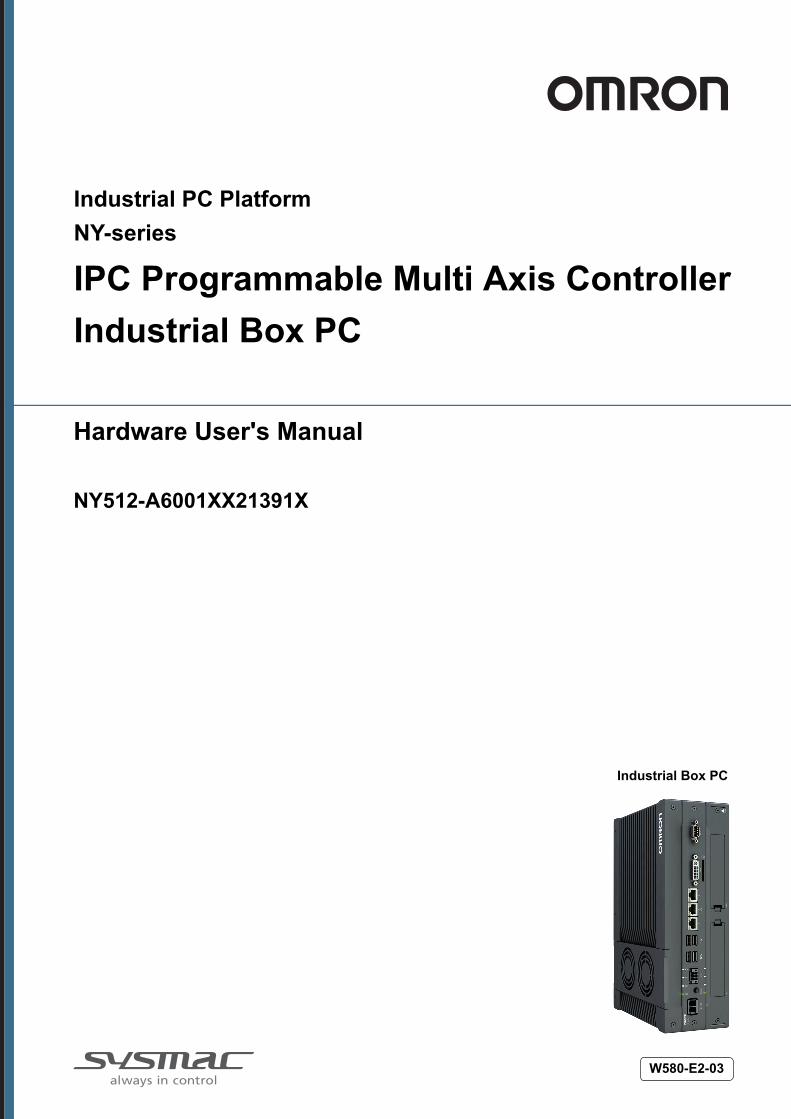
Industrial PC PlatformNY-series
IPC Programmable Multi Axis Controller Industrial Box PC
Hardware User's Manual
NY512-A6001XX21391X
Industrial Box PC
W580-E2-03
NOTEAll rights reserved. No part of this publication may be reproduced, stored in a retrieval system, ortransmitted, in any form, or by any means, mechanical, electronic, photocopying, recording, or other-wise, without the prior written permission of OMRON.No patent liability is assumed with respect to the use of the information contained herein. Moreover,because OMRON is constantly striving to improve its high-quality products, the information containedin this manual is subject to change without notice. Every precaution has been taken in the preparationof this manual. Nevertheless, OMRON assumes no responsibility for errors or omissions. Neither isany liability assumed for damages resulting from the use of the information contained in this publica-tion.
Trademarks• Sysmac and SYSMAC are trademarks or registered trademarks of OMRON Corporation in Japan
and other countries for OMRON factory automation products.• Windows, Visual Basic and Visual Studio are either registered trademarks or trademarks of Micro-
soft Corporation in the USA and other countries.• EtherCAT® is registered trademark and patented technology, licensed by Beckhoff Automation
GmbH, Germany.• ODVA, CIP, CompoNet, DeviceNet, and EtherNet/IP are trademarks of ODVA.
• The SD and SDHC logos are trademarks of SD-3C, LLC. • Intel, the Intel Logo, Celeron and Intel Core are trademarks or registered trademarks of Intel Corpo-
ration or its subsidiaries in the USA and other countries.Other company names and product names in this document are the trademarks or registered trade-marks of their respective companies.
CopyrightsMicrosoft product screen shots reprinted with permission from Microsoft Corporation.
IntroductionThank you for purchasing the IPC Programmable Multi Axis Controller.This manual contains information that is necessary to use the IPC Programmable Multi Axis Controller(hereafter also named as Box PC). Please read this manual and make sure you understand the func-tionality and performance of the Box PC before attempting to use it.Keep this manual in a safe place where it will be available for reference during operation.
Intended AudienceThis manual is intended for the following personnel, who must also have knowledge of electrical sys-tems (an electrical engineer or the equivalent).• Personnel in charge of introducing Factory Automation systems.• Personnel in charge of designing Factory Automation systems.• Personnel in charge of installing and maintaining Factory Automation systems.• Personnel in charge of managing Factory Automation systems and facilities.
Applicable ProductsThis manual covers following IPC Programmable Multi Axis Controller product:• NY512-A6001XX21391X
Additional Information
Refer to 1-5 Product Configuration on page 1 - 6 for configuration details.
Introduction
1NY-series IPC Programmable Multi Axis Controller Hardware User's Manual (W580)
CONTENTSIntroduction .............................................................................................................. 1
Intended Audience...........................................................................................................................................1Applicable Products .........................................................................................................................................1
Manual Information.................................................................................................. 7Page Structure.................................................................................................................................................7Special Information ..........................................................................................................................................8
Terms and Conditions Agreement.......................................................................... 9Warranty and Limitations of Liability ................................................................................................................9Application Considerations ............................................................................................................................10Disclaimers ....................................................................................................................................................10
Safety Precautions................................................................................................. 12Definition of Precautionary Information..........................................................................................................12Symbols .........................................................................................................................................................12Warnings........................................................................................................................................................13Cautions.........................................................................................................................................................15
Precautions for Safe Use ...................................................................................... 16Disassembly, Dropping, Mounting, Installation and Storage .........................................................................16Wiring.............................................................................................................................................................16Power Supply Design and Turning ON/OFF the Power Supply.....................................................................16Actual Operation ............................................................................................................................................17Operation .......................................................................................................................................................17General Communications ..............................................................................................................................18Battery Replacement .....................................................................................................................................18EtherCAT Communications............................................................................................................................18Motion Control ...............................................................................................................................................19Product Replacement ....................................................................................................................................19Cleaning, Maintenance and Disposal ............................................................................................................19
Precautions for Correct Use ................................................................................. 20Storage, Installation and Mounting ................................................................................................................20Wiring.............................................................................................................................................................20Actual Operation and Operation ....................................................................................................................21Battery Replacement .....................................................................................................................................21SD Memory Cards .........................................................................................................................................21USB Flash Drives ..........................................................................................................................................21Motion Control ...............................................................................................................................................21EtherCAT Communications............................................................................................................................22
Regulations and Standards .................................................................................. 23Conformance to EU Directives ......................................................................................................................23Conformance to KC Standards......................................................................................................................24Conformance to UL and CSA Standards.......................................................................................................24Software Licenses and Copyrights ................................................................................................................24
Related Manuals..................................................................................................... 25Related Products Manuals.............................................................................................................................25Industrial Monitor Manual ..............................................................................................................................25
Terminology and Abbreviations ........................................................................... 26Industrial PC Platform ...................................................................................................................................26Hardware ......................................................................................................................................................26Software.........................................................................................................................................................27
CONTENTS
2 NY-series IPC Programmable Multi Axis Controller Hardware User's Manual (W580)

Revision History..................................................................................................... 28
Sections in this Manual ......................................................................................... 29
Section 1 Overview1-1 Intended Use .......................................................................................................................1 - 21-2 Hardware Features...............................................................................................................1 - 31-3 Software Features................................................................................................................1 - 41-4 ID Information Label ............................................................................................................1 - 5
1-4-1 Label with Controller License (Optional) ...................................................................................1 - 5
1-5 Product Configuration.........................................................................................................1 - 61-6 Industrial PC Platform Overview ........................................................................................1 - 7
1-6-1 Industrial Monitor ......................................................................................................................1 - 71-6-2 Industrial Box PC .....................................................................................................................1 - 8
Section 2 Hardware2-1 System Configuration..........................................................................................................2 - 32-2 Component Names and Functions.....................................................................................2 - 4
2-2-1 Front and Top of the Industrial Box PC .....................................................................................2 - 42-2-2 Back of the Industrial Box PC ...................................................................................................2 - 6
2-3 LED Indicators......................................................................................................................2 - 72-3-1 PWR LED Indicator ...................................................................................................................2 - 72-3-2 ERR LED Indicator ....................................................................................................................2 - 82-3-3 HDD LED Indicator....................................................................................................................2 - 82-3-4 RUN LED Indicator....................................................................................................................2 - 8
2-4 Power Button........................................................................................................................2 - 92-5 Drive Bays ..........................................................................................................................2 - 102-6 SD Memory Card Slot ........................................................................................................ 2 - 112-7 PCIe Card Slot ....................................................................................................................2 - 122-8 Connectors .........................................................................................................................2 - 13
2-8-1 Power Connector ....................................................................................................................2 - 132-8-2 I/O Connector ..........................................................................................................................2 - 132-8-3 USB Connectors .....................................................................................................................2 - 142-8-4 Ethernet Connectors ...............................................................................................................2 - 152-8-5 DVI Connector.........................................................................................................................2 - 152-8-6 RS-232C Connector (Optional) ...............................................................................................2 - 16
2-9 Spare Parts .........................................................................................................................2 - 172-9-1 Battery.....................................................................................................................................2 - 172-9-2 Fan Unit...................................................................................................................................2 - 172-9-3 Accessory Kit ..........................................................................................................................2 - 18
2-10 Optional Hardware .............................................................................................................2 - 192-10-1 Mounting Brackets ..................................................................................................................2 - 192-10-2 SD Memory Cards...................................................................................................................2 - 192-10-3 USB Flash Drives....................................................................................................................2 - 202-10-4 Storage Devices......................................................................................................................2 - 202-10-5 DVI Cables ..............................................................................................................................2 - 212-10-6 USB Type-A to USB Type-B Cables .......................................................................................2 - 212-10-7 Industrial Monitor ....................................................................................................................2 - 222-10-8 Power Supply ..........................................................................................................................2 - 222-10-9 UPS.........................................................................................................................................2 - 23
CONTENTS
3NY-series IPC Programmable Multi Axis Controller Hardware User's Manual (W580)

2-10-10 UPS Communication Cable ....................................................................................................2 - 232-10-11 Recommended EtherCAT Cables ...........................................................................................2 - 24
Section 3 Software3-1 Windows Operating System ...............................................................................................3 - 2
3-1-1 Determine Your Version of the Windows Operating Systems ...................................................3 - 2
3-2 Support Software .................................................................................................................3 - 33-2-1 Available IPC Programmable Multi Axis Controller Support Software ......................................3 - 33-2-2 Overview IPC Support Software for Windows...........................................................................3 - 43-2-3 Power PMAC Support Utility .....................................................................................................3 - 53-2-4 Industrial PC Support Utility .....................................................................................................3 - 63-2-5 Industrial PC Tray Utility .........................................................................................................3 - 103-2-6 Power Attendant Lite Utility .....................................................................................................3 - 13
3-3 Software for Developers....................................................................................................3 - 163-3-1 Overview IPC Developer Software for Windows.....................................................................3 - 163-3-2 Industrial PC System API .......................................................................................................3 - 16
Section 4 Specifications4-1 General Specifications .......................................................................................................4 - 2
4-1-1 Dimensions and Weight ............................................................................................................4 - 24-1-2 General Electrical Specifications...............................................................................................4 - 34-1-3 Power Consumption Specifications...........................................................................................4 - 44-1-4 CPU Specifications ...................................................................................................................4 - 54-1-5 Memory Specifications ..............................................................................................................4 - 54-1-6 Storage Device Specifications ..................................................................................................4 - 64-1-7 PCIe Card Specifications ..........................................................................................................4 - 74-1-8 Bracket Specifications...............................................................................................................4 - 8
4-2 Connector Specifications ...................................................................................................4 - 94-2-1 Power Connector Specifications ...............................................................................................4 - 94-2-2 I/O Connector Specifications...................................................................................................4 - 104-2-3 USB Connector Specifications ................................................................................................4 - 144-2-4 Ethernet Connector Specifications..........................................................................................4 - 154-2-5 DVI Connector Specifications .................................................................................................4 - 184-2-6 RS-232C Connector Specifications.........................................................................................4 - 19
4-3 Software Specifications ...................................................................................................4 - 204-3-1 Available Windows Operating Systems...................................................................................4 - 204-3-2 Supported Languages.............................................................................................................4 - 20
4-4 Environmental Specifications...........................................................................................4 - 214-4-1 Operation Environment Specifications ....................................................................................4 - 214-4-2 Temperature and Humidity Specifications...............................................................................4 - 224-4-3 Recycling Specifications .........................................................................................................4 - 23
Section 5 Installation5-1 Unpack..................................................................................................................................5 - 3
5-1-1 Unpack Procedure ....................................................................................................................5 - 35-1-2 Items Supplied ..........................................................................................................................5 - 3
5-2 Install Options ......................................................................................................................5 - 65-2-1 Install a Drive ............................................................................................................................5 - 65-2-2 Install the PCIe Card ...............................................................................................................5 - 10
5-3 Mount ..................................................................................................................................5 - 155-3-1 Installation Method in Control Panels......................................................................................5 - 155-3-2 Product Orientation .................................................................................................................5 - 16
CONTENTS
4 NY-series IPC Programmable Multi Axis Controller Hardware User's Manual (W580)
5-3-3 Temperature ............................................................................................................................5 - 165-3-4 Humidity ..................................................................................................................................5 - 195-3-5 Vibration and Shock ................................................................................................................5 - 195-3-6 Atmosphere.............................................................................................................................5 - 205-3-7 Electrical Environment ............................................................................................................5 - 205-3-8 Book Mount Procedure ...........................................................................................................5 - 255-3-9 Wall Mount Procedure.............................................................................................................5 - 26
5-4 Wire .....................................................................................................................................5 - 275-4-1 Wiring Warnings and Cautions................................................................................................5 - 275-4-2 Ground ....................................................................................................................................5 - 285-4-3 Wire the Power Connector ......................................................................................................5 - 355-4-4 Wire the I/O Connector ...........................................................................................................5 - 38
5-5 Connect...............................................................................................................................5 - 415-5-1 Connector Identification ..........................................................................................................5 - 425-5-2 Connection Procedure ............................................................................................................5 - 435-5-3 Ethernet Connection Procedure..............................................................................................5 - 44
5-6 Initial Power ON .................................................................................................................5 - 455-6-1 Initial Power ON Procedure.....................................................................................................5 - 455-6-2 Windows Startup First Time ....................................................................................................5 - 47
5-7 Install Software ..................................................................................................................5 - 495-7-1 Internet Browser......................................................................................................................5 - 495-7-2 Firewall ....................................................................................................................................5 - 505-7-3 Anti-virus Software ..................................................................................................................5 - 505-7-4 Drivers and Custom Software .................................................................................................5 - 515-7-5 Customize Windows................................................................................................................5 - 51
5-8 Connect UPS ......................................................................................................................5 - 525-8-1 Connect UPS Using the USB Connector ................................................................................5 - 535-8-2 Connect UPS Using the I/O Connector ...................................................................................5 - 56
5-9 Create a Windows System Repair Disk and a Windows Backup ..................................5 - 595-9-1 Industrial PC with Programmable Multi Axis Controller Backup..............................................5 - 595-9-2 Create a Windows System Repair Disk ..................................................................................5 - 59
Section 6 Operating Procedures6-1 Power ON..............................................................................................................................6 - 2
6-1-1 Power ON Using the Power Button...........................................................................................6 - 26-1-2 Power ON Using the Power ON/OFF Input...............................................................................6 - 26-1-3 Auto Power ON .........................................................................................................................6 - 2
6-2 Power OFF............................................................................................................................6 - 36-2-1 Power OFF Using the Power PMAC Support Utility..................................................................6 - 36-2-2 Forced Power OFF Using the Power Button.............................................................................6 - 3
6-3 React to Product Messages................................................................................................6 - 56-4 React to Windows Messages..............................................................................................6 - 6
Section 7 Maintenance7-1 Preventive Maintenance......................................................................................................7 - 2
7-1-1 Preventive Maintenance Schedule............................................................................................7 - 27-1-2 Clean the Box PC......................................................................................................................7 - 47-1-3 Keep Software Updated ............................................................................................................7 - 47-1-4 Create a Custom Backup with Windows Backup ......................................................................7 - 5
7-2 Corrective Maintenance ......................................................................................................7 - 87-2-1 Warning and Error Messages....................................................................................................7 - 87-2-2 Remove the Cover ..................................................................................................................7 - 107-2-3 Replace the Fan Unit ..............................................................................................................7 - 117-2-4 Replace the Battery.................................................................................................................7 - 13
CONTENTS
5NY-series IPC Programmable Multi Axis Controller Hardware User's Manual (W580)
7-2-5 Replace a Drive.......................................................................................................................7 - 157-2-6 Replace the PCIe Card ...........................................................................................................7 - 207-2-7 Restore and Repair Data ........................................................................................................7 - 247-2-8 Allocate a Drive in Windows....................................................................................................7 - 297-2-9 Windows Event Viewer............................................................................................................7 - 30
AppendicesA-1 BIOS ..................................................................................................................................... A - 2
A-1-1 BIOS Overview......................................................................................................................... A - 2A-1-2 BIOS - Main.............................................................................................................................. A - 4A-1-3 BIOS - Advanced ..................................................................................................................... A - 5A-1-4 BIOS - Chipset ......................................................................................................................... A - 8A-1-5 BIOS - Boot .............................................................................................................................. A - 9A-1-6 BIOS - Security ...................................................................................................................... A - 10A-1-7 BIOS - Save & Exit ................................................................................................................. A - 10
A-2 Customize Windows ......................................................................................................... A - 11A-2-1 Enhanced Write Filter..............................................................................................................A - 11A-2-2 File-Based Write Filter............................................................................................................ A - 12
A-3 DVI-I Connector Pin Details ............................................................................................. A - 14A-4 RS-232C Connector Pin Details....................................................................................... A - 16
Index
CONTENTS
6 NY-series IPC Programmable Multi Axis Controller Hardware User's Manual (W580)
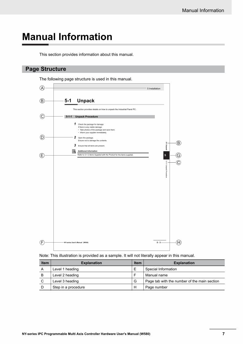
Manual InformationThis section provides information about this manual.
Page StructureThe following page structure is used in this manual.
A
B
C
C D
E
F
B
C
H
5 Installation
5 - 3NY-series User's Manual (W555)
5-1
Un
pa
ck
5
5-1
-1 U
np
ack P
roce
du
re
G
5-1 Unpack
This section provides details on how to unpack the Industrial Panel PC.
5-1-1 Unpack Procedure
1 Check the package for damage.
If there is any visible damage:
• Take photos of the package and save them.
• Inform your supplier immediately.
2 Open the package.
Ensure not to damage the contents.
3 Ensure that all items are present.
Additional Information
Refer to 5-1-2 Items Supplied with the Product for the items supplied.
Note: This illustration is provided as a sample. It will not literally appear in this manual.
Item Explanation Item ExplanationA Level 1 heading E Special InformationB Level 2 heading F Manual nameC Level 3 heading G Page tab with the number of the main sectionD Step in a procedure H Page number
Manual Information
7NY-series IPC Programmable Multi Axis Controller Hardware User's Manual (W580)

Special InformationSpecial information in this manual is classified as follows:
Precautions for Safe Use
Precautions on what to do and what not to do to ensure safe usage of the product.
Precautions for Correct Use
Precautions on what to do and what not to do to ensure proper operation and performance.
Additional Information
Additional information to read as required.This information is provided to increase understanding or make operation easier.
Version Information
Information on differences in specifications and functionality between different versions.
Manual Information
8 NY-series IPC Programmable Multi Axis Controller Hardware User's Manual (W580)

Terms and Conditions Agreement
Warranty and Limitations of Liability
Warranty• Exclusive Warranty
Omron’s exclusive warranty is that the Products will be free from defects in materials and workman-ship for a period of twelve months from the date of sale by Omron (or such other period expressedin writing by Omron). Omron disclaims all other warranties, expressed or implied.
• LimitationsOMRON MAKES NO WARRANTY OR REPRESENTATION, EXPRESS OR IMPLIED, ABOUTNON-INFRINGEMENT, MERCHANTABILITY OR FITNESS FOR A PARTICULAR PURPOSE OFTHE PRODUCTS. BUYER ACKNOWLEDGES THAT IT ALONE HAS DETERMINED THAT THEPRODUCTS WILL SUITABLY MEET THE REQUIREMENTS OF THEIR INTENDED USE.Omron further disclaims all warranties and responsibility of any type for claims or expenses basedon infringement by the Products or otherwise of any intellectual property right.
• Buyer RemedyOmron’s sole obligation hereunder shall be, at Omron’s election, to (i) replace (in the form originallyshipped with Buyer responsible for labor charges for removal or replacement thereof) the non-com-plying Product, (ii) repair the non-complying Product, or (iii) repay or credit Buyer an amount equalto the purchase price of the non-complying Product; provided that in no event shall Omron be re-sponsible for warranty, repair, indemnity or any other claims or expenses regarding the Products un-less Omron’s analysis confirms that the Products were properly handled, stored, installed and main-tained and not subject to contamination, abuse, misuse or inappropriate modification. Return of anyProducts by Buyer must be approved in writing by Omron before shipment. Omron Companies shallnot be liable for the suitability or unsuitability or the results from the use of Products in combinationwith any electrical or electronic components, circuits, system assemblies or any other materials orsubstances or environments. Any advice, recommendations or information given orally or in writing,are not to be construed as an amendment or addition to the above warranty.
See http://www.omron.com/global/ or contact your Omron representative for published information.
Limitations of LiabilityOMRON COMPANIES SHALL NOT BE LIABLE FOR SPECIAL, INDIRECT, INCIDENTAL, OR CON-SEQUENTIAL DAMAGES, LOSS OF PROFITS OR PRODUCTION OR COMMERCIAL LOSS IN ANYWAY CONNECTED WITH THE PRODUCTS, WHETHER SUCH CLAIM IS BASED IN CONTRACT,WARRANTY, NEGLIGENCE OR STRICT LIABILITY. Further, in no event shall liability of Omron Com-panies exceed the individual price of the Product on which liability is asserted.
Terms and Conditions Agreement
9NY-series IPC Programmable Multi Axis Controller Hardware User's Manual (W580)
Application Considerations
Suitability for UseOmron Companies shall not be responsible for conformity with any standards, codes or regulationswhich apply to the combination of the Product in the Buyer’s application or use of the Product. At Buy-er’s request, Omron will provide applicable third party certification documents identifying ratings andlimitations of use which apply to the Product. This information by itself is not sufficient for a completedetermination of the suitability of the Product in combination with the end product, machine, system, orother application or use. Buyer shall be solely responsible for determining appropriateness of the par-ticular Product with respect to Buyer’s application, product or system. Buyer shall take application re-sponsibility in all cases.NEVER USE THE PRODUCT FOR AN APPLICATION INVOLVING SERIOUS RISK TO LIFE ORPROPERTY WITHOUT ENSURING THAT THE SYSTEM AS A WHOLE HAS BEEN DESIGNED TOADDRESS THE RISKS, AND THAT THE OMRON PRODUCT(S) IS PROPERLY RATED AND IN-STALLED FOR THE INTENDED USE WITHIN THE OVERALL EQUIPMENT OR SYSTEM.
Programmable Products• Omron Companies shall not be responsible for the user’s programming of a programmable Product,
or any consequence thereof.• Omron Companies shall not be responsible for the operation of the user accessible operating sys-
tem (e.g. Windows, Linux), or any consequence thereof.
Disclaimers
Performance DataData presented in Omron Company websites, catalogs and other materials is provided as a guide forthe user in determining suitability and does not constitute a warranty. It may represent the result ofOmron’s test conditions, and the user must correlate it to actual application requirements. Actual per-formance is subject to the Omron’s Warranty and Limitations of Liability.
Change in SpecificationsProduct specifications and accessories may be changed at any time based on improvements and oth-er reasons. It is our practice to change part numbers when published ratings or features are changed,or when significant construction changes are made. However, some specifications of the Product maybe changed without any notice. When in doubt, special part numbers may be assigned to fix or estab-lish key specifications for your application. Please consult with your Omron’s representative at anytime to confirm actual specifications of purchased Product.
Terms and Conditions Agreement
10 NY-series IPC Programmable Multi Axis Controller Hardware User's Manual (W580)

Errors and OmissionsInformation presented by Omron Companies has been checked and is believed to be accurate; how-ever, no responsibility is assumed for clerical, typographical or proofreading errors or omissions.
Terms and Conditions Agreement
11NY-series IPC Programmable Multi Axis Controller Hardware User's Manual (W580)
Safety Precautions
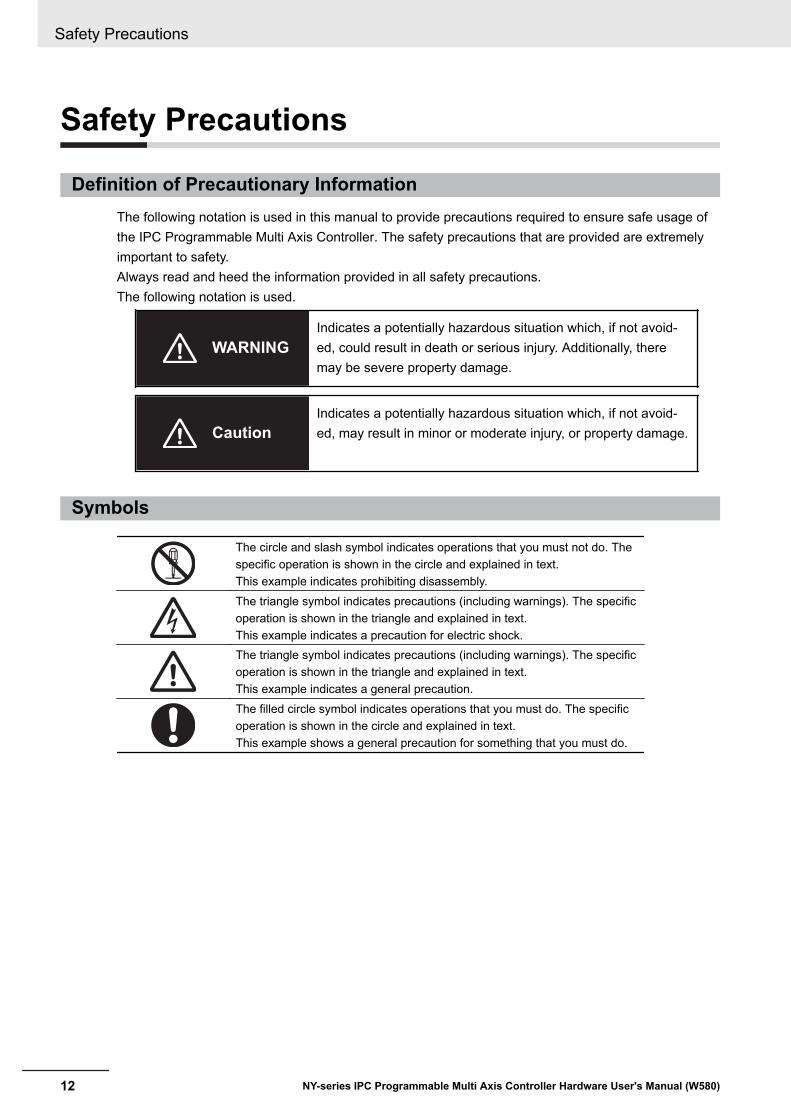
Definition of Precautionary InformationThe following notation is used in this manual to provide precautions required to ensure safe usage ofthe IPC Programmable Multi Axis Controller. The safety precautions that are provided are extremelyimportant to safety.Always read and heed the information provided in all safety precautions.The following notation is used.
WARNINGIndicates a potentially hazardous situation which, if not avoid-ed, could result in death or serious injury. Additionally, theremay be severe property damage.
CautionIndicates a potentially hazardous situation which, if not avoid-ed, may result in minor or moderate injury, or property damage.
Symbols
The circle and slash symbol indicates operations that you must not do. Thespecific operation is shown in the circle and explained in text.This example indicates prohibiting disassembly.The triangle symbol indicates precautions (including warnings). The specificoperation is shown in the triangle and explained in text.This example indicates a precaution for electric shock.The triangle symbol indicates precautions (including warnings). The specificoperation is shown in the triangle and explained in text.This example indicates a general precaution.The filled circle symbol indicates operations that you must do. The specificoperation is shown in the circle and explained in text.This example shows a general precaution for something that you must do.
Safety Precautions
12 NY-series IPC Programmable Multi Axis Controller Hardware User's Manual (W580)

Warnings
WARNING
Disassembly and Dropping
Do not attempt to disassemble, repair, or modify the product in any way. Do-ing so may result in malfunction or fire.In particular, high-voltage parts are present in the Controller while power issupplied or immediately after power is turned OFF. Touching any of theseparts may result in electric shock. There are also sharp internal parts thatmay cause injury.
Installation
Always connect to a ground of 100 Ω or less when installing the product.
Ensure that installation and post-installation checks of the product are per-formed by personnel in charge who possess a thorough understanding ofthe machinery to be installed.
Fail-safe Measures
Provide safety measures in external circuits to ensure safety in the system ifan abnormality occurs due to malfunction of the product or due to other ex-ternal factors affecting operation. Not doing so may result in serious acci-dents due to incorrect operation.Emergency stop circuits, interlock circuit, limit circuits, and similar safetymeasures must be provided in external control circuits.
The product will turn OFF all outputs from Output Units in the following cas-es. The slaves will operate according to the settings in the slaves.• If an error occurs in the power supply• If a controller error occurs• While the product is in Standby until EtherCAT communication is started
after the power is turned ONExternal safety measures must be provided to ensure safe operation of thesystem in such cases.If external power supplies for slaves or other devices are overloaded orshort-circuited, the voltage will drop, outputs will turn OFF, and the systemmay be unable to read inputs. Provide external safety measures in controlswith monitoring of external power supply voltage as required so that the sys-tem operates safely in such a case.Unintended behavior may occur when an error occurs in internal memory ofthe product. As a countermeasure for such problems, external safety meas-ures must be provided to ensure safe operation of the system.
Safety Precautions
13NY-series IPC Programmable Multi Axis Controller Hardware User's Manual (W580)
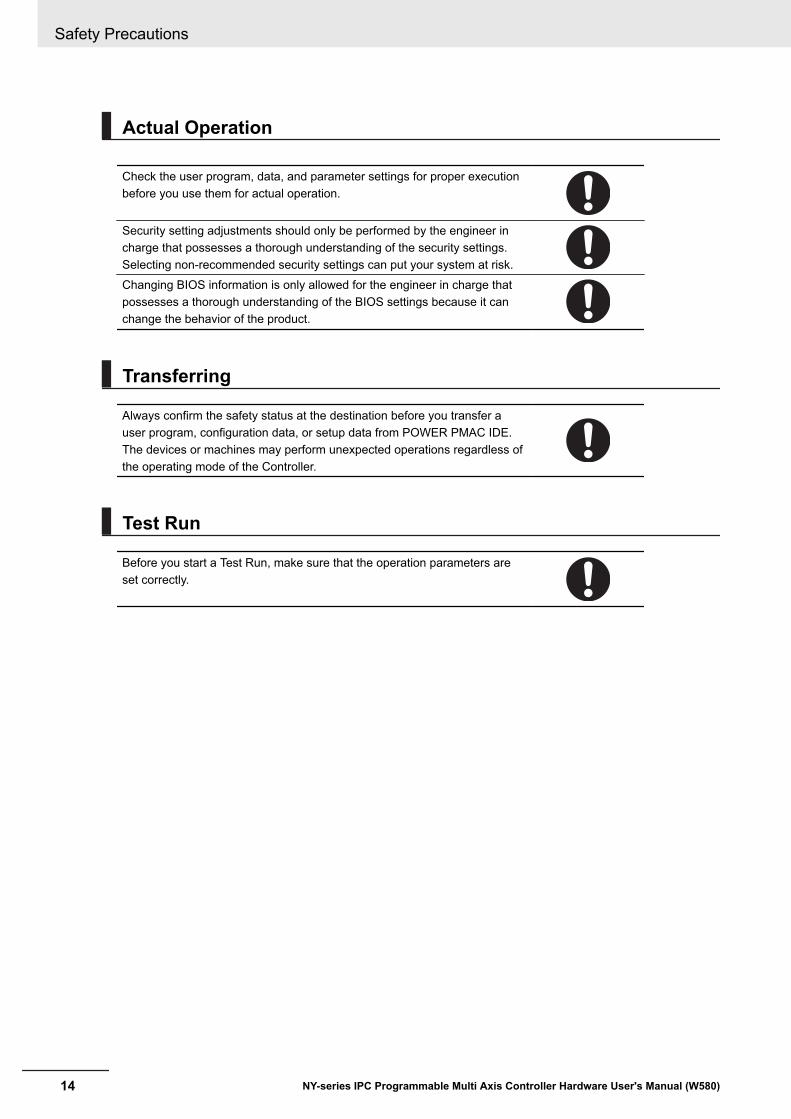
Actual Operation
Check the user program, data, and parameter settings for proper executionbefore you use them for actual operation.
Security setting adjustments should only be performed by the engineer incharge that possesses a thorough understanding of the security settings.Selecting non-recommended security settings can put your system at risk.Changing BIOS information is only allowed for the engineer in charge thatpossesses a thorough understanding of the BIOS settings because it canchange the behavior of the product.
Transferring
Always confirm the safety status at the destination before you transfer auser program, configuration data, or setup data from POWER PMAC IDE.The devices or machines may perform unexpected operations regardless ofthe operating mode of the Controller.
Test Run
Before you start a Test Run, make sure that the operation parameters areset correctly.
Safety Precautions
14 NY-series IPC Programmable Multi Axis Controller Hardware User's Manual (W580)

Cautions
Caution
Wiring
The product has an internal non-isolated DC power supply. Circuit ground (0VDC) and frame ground are connected together. When connecting a non-isolated device or a non-isolated interface to the product, take appropriateactions to avoid communication failures or damage to the mentioned ports.
Industrial PC Platform Product Non-isolated
Device
Non-isolated
Interface
24 VDC
0 VDC
Never ground the 24 VDC side of the power supply. This may cause a shortcircuit.
Safety Precautions
15NY-series IPC Programmable Multi Axis Controller Hardware User's Manual (W580)

Precautions for Safe Use
Disassembly, Dropping, Mounting, Installation and Storage• Do not drop the product or subject it to abnormal vibration or shock. Doing so may result in product
malfunction or burning.• When unpacking, check carefully for any external scratches or other damages. Also, shake the
product gently and check for any abnormal sound.• Always use the devices specified in the relevant manual.• The product must be installed in a control panel.• Always install equipment that is included in the product specifications. Not doing so may result in
failure or malfunction.• If the storage period exceeds 6 months, check the performance of the Fan Unit before production
starts.• Install the product in the correct orientation and temperature according to the specifications in the
manual to prevent overheating. Not doing so may result in malfunction.• When connecting peripheral devices to the product, ensure sufficient countermeasures against
noise and static electricity during installation of the peripheral devices.
Wiring• Follow the instructions in the manual to correctly perform connector wiring and insertion. Double-
check all wiring and connector insertion before turning ON the power supply.• Always ensure connectors, cables, PCIe Cards and Storage devices are completely locked in place
to prevent accidental disconnection.• Before you connect a computer to the product, disconnect the power supply plug of the computer
from the AC outlet. Also, if the computer has an FG terminal, make the connections so that the FGterminal has the same electrical potential as the product. A difference in electrical potential betweenthe computer and the product may cause failure or malfunction.
• Do not bend or pull the cables beyond normal limit. Do not place heavy objects on top of the cablesor other wiring lines. Doing so may break the cables.
• Always use power supply wires with sufficient wire diameters to prevent voltage drop and burning.Make sure that the current capacity of the wire is sufficient. Otherwise, excessive heat may be gen-erated. When cross-wiring terminals, the total current for all the terminals will flow in the wire. Whenwiring cross-overs, make sure that the current capacity of each of the wires is not exceeded.
• Be sure that all mounting bracket screws and cable connector screws are tightened to the torquespecified in the relevant manuals. The loose screws may result in fire or malfunction.
• Use crimp terminals for wiring.• For an NY Monitor Link connection, always follow the cable type and connection method specifica-
tions in the manual. Otherwise, communications may be faulty.
Power Supply Design and Turning ON/OFF the Power Supply• Always use a power supply that provides power within the rated range.• Do not perform a dielectric strength test.
Precautions for Safe Use
16 NY-series IPC Programmable Multi Axis Controller Hardware User's Manual (W580)

• Always use the recommended uninterruptible power supply (UPS) to prevent data loss and othersystem file integrity issues caused by unexpected power interruption. Back up the system files in theplanned way to prevent data loss and other system file integrity issues caused by incorrect opera-tion.
• Use an Omron S8BA UPS with the correct revision number to prevent improper system shutdown.• Power ON after the DVI cable is connected between the product and an external monitor.• Always check the power supply and power connections before applying power. Incorrect power con-
nections can damage the product or cause burning.• Always turn OFF the power supply to system before you attempt any of the following.
• Inserting or removing PCIe Cards• Connecting cables• Connecting or disconnecting the connectors• Wiring the system• Replacing or removing the HDD/SSD• Replacing the Battery• Replacing the Fan Unit
• Do not turn off the power supply or remove the USB memory device while the Controller is access-ing the USB memory device. Data may become corrupted, and the Controller will not operate cor-rectly if it uses corrupted data.
• Always turn OFF the power supply before you attempt any of the following. Connecting cables orwiring the system Connecting or disconnecting the connectors.
• Do not disconnect the cable or turn OFF the power supply to the Controller when downloading dataor programs from Support Software. Doing so interrupts the data transfer, and a malfunction mayoccur.
Actual Operation• Choose a OS password that is not obvious to prevent unauthorized access.• Remember the OS user name and password. The product is inaccessible without it.• Before operating the system , please make sure the appropriate software is installed and config-
ured. Doing so may prevent unexpected operation.• Install all updates and ensure the browser stays up-to-date.• Install all updates and ensure the firewall stays up-to-date.• Make sure that your OS environment is protected against malicious software and viruses.• Install all updates and ensure virus definitions stay up-to-date.• Do not remove the fan cover while the power is ON. Contact with a rotating fan may result in injury.• Virtual memory settings can affect the performance of the system. Disable the paging file after in-
stallation of applications or updates.• Correctly perform wiring and setting, and ensure that the shutdown by the UPS can be executed.• The task execution times in the physical Controller depends on load of operating system applica-
tions. Before starting actual operation, you must test performance under all foreseeable conditionson the actual system.
Operation• Do not carry out the following operations when accessing a USB device or an SD Memory Card.
• Turn OFF the power supply of the product.
Precautions for Safe Use
17NY-series IPC Programmable Multi Axis Controller Hardware User's Manual (W580)
• Press the Power Button of the product.• Remove a USB device or SD memory card.
• Do not attempt to remove or touch the fan unit while the product is powered ON or immediately afterthe power supply is turned OFF. If you attempt to replace the fan unit then, there is a risk of personalinjury due to hot or rotating parts.
• Press the power button for several seconds to force the product shutdown. Always back up files inthe planned way to prevent data loss or system file corruption.
• Do not touch any product housing when power is being supplied or immediately after the power sup-ply is turned OFF. Doing so may result in burn injury.
• Confirm that no adverse effects will occur in the system before you attempt any of the following.• Changing the operating mode of the Controller (including changing the setting of the Startup
Mode).• Changing the user program or settings.• Changing set values or present values.
General Communications• Separate the machine network segment from the office network to avoid communication failures.
Battery Replacement• Dispose of any Battery that has been dropped on the floor or otherwise subjected to excessive
shock. Batteries that have been subjected to shock may leak if they are used.• UL standards require that only an experienced engineer replace the Battery. Make sure that an ex-
perienced engineer is in charge of Battery replacement.• The Battery may leak, rupture, heat, or ignite. Never short-circuit, charge, disassemble, heat, or in-
cinerate the Battery or subject it to strong shock.
EtherCAT Communications• Make sure that the communications distance, number of nodes connected, and method of connec-
tion for EtherCAT are within specifications. Do not connect EtherCAT communications to a standardin-house LAN, or other net-works. An overload may cause the network to fail or malfunction.
• If noise occurs or an EtherCAT slave is disconnected from the network, any current communicationsframes may be lost. If frames are lost, slave I/O data is not communicated, and unintended opera-tion may occur. The slave outputs will behave according to the slave specifications.
• EtherCAT communications are not always established immediately after the power supply is turnedON. Use the ECAT Network General Configuration Elements in the user program to confirm thatcommunications are established before attempting control operations.
• When an EtherCAT slave is disconnected or disabled, communications will stop and control of theoutputs will be lost not only for the disconnected slave, but for all slaves connected after it. Confirmthat the system will not be adversely affected before you disconnect or disable a slave.
• You cannot use standard Ethernet hubs or repeater hubs with EtherCAT communications. If you useone of these, a major fault level error or other error may occur.
• If you need to disconnect the cable from an EtherCAT slave during operation, change to Init Statusthe EtherCAT slave and all of the EtherCAT slaves that are connected after it.
Precautions for Safe Use
18 NY-series IPC Programmable Multi Axis Controller Hardware User's Manual (W580)

• For EtherCAT and EtherNet, use the connection methods and cables that are specified in this man-ual. Otherwise, communications may be faulty.
• It takes up to approximately 30 to 40 s to start EtherCAT communication after the power is turnedON. The outputs during this time behave according to the slave or Output Unit specifications. Imple-ment fail-safe circuits so that external devices do not operate incorrectly.
Motion Control• The motor is stopped if communications are interrupted between the Power PMAC IDE and the
product during a Test Run. Connect the communications cable between the computer and productsecurely and confirm that the system will not be adversely affected before you perform a Test Run.
• Confirm the axis number carefully before you perform a Test Run.
Product Replacement• Make sure that the required data, including the user program, configurations, settings and variables
is transferred to a product that was replaced and to externally connected devices before restartingoperation.
Cleaning, Maintenance and Disposal• Do not use corrosive substances to clean the product. Doing so may result in the failure or malfunc-
tion.• Dispose of the product and batteries according to local ordinances as they apply.
• The following information must be displayed for all products that contain primary lithium batterieswith a perchlorate content of 6 ppb or higher when shipped to or transported through the State ofCalifornia, USA.
Perchlorate Material - special handling may apply.See http://www.dtsc.ca.gov/hazardouswaste/perchlorate.
• The product contains a lithium battery with a perchlorate content of 6ppb or higher. When exportingan end product containing the product to or shipping through California, USA, label all packing andshipping containers appropriately.
Precautions for Safe Use
19NY-series IPC Programmable Multi Axis Controller Hardware User's Manual (W580)
Precautions for Correct Use
Storage, Installation and Mounting• Do not operate or store the product in the following locations. Operation may stop or malfunctions
may occur.• Locations subject to direct sunlight• Locations subject to temperatures or humidity outside the range specified in the specifications• Locations subject to condensation as the result of severe changes in temperature• Locations subject to corrosive or flammable gases• Locations subject to dust (especially iron dust) or salts• Locations subject to exposure to water, oil or chemicals• Locations subject to shock or vibration• Locations outdoors subject to direct wind and rain• Locations subject to strong ultraviolet light
• Always install the product with sufficient surrounding space to allow for adequate heat dissipationand cooling effect.
• Take appropriate and sufficient countermeasures when installing the product in the following loca-tions• Locations subject to strong, high-frequency noise• Locations subject to static electricity or other forms of noise• Locations subject to strong electromagnetic fields• Locations subject to possible exposure to radioactivity• Locations close to power lines
• Always touch a grounded piece of metal to discharge static electricity from your body before startingan installation or maintenance procedure.
• Insert USB devices and PCIe devices correctly to avoid the burning, failure or malfunction.• Execute a backup of the product before PCIe addition or replacement. Be sure that the PCIe device
works correctly before you use them for actual operation. PCIe devices and their related softwaremay cause an OS boot failure or crash.
• Ensure the selected operating system supports ACPI to enable operating system shutdown usingthe power button.
• Download the enhanced Video Driver from the OMRON Download Center and install it on the Indus-trial PC.
Wiring• Always ensure the rated supply voltage is connected to the product.• Do not allow wire clippings, shavings, or other foreign material to enter the product. Otherwise, burn-
ing, failure, or malfunction may occur. Cover the product or take other suitable countermeasures, es-pecially during wiring work.
• Do not use cables exceeding the maximum specified length. Doing so may cause malfunction.• Do not connect an AC power supply to the DC power connector.• Observe the following precautions to prevent broken wires.
• When you remove the sheath, be careful not to damage the conductor.• Connect the conductor without twisting the wires.
Precautions for Correct Use
20 NY-series IPC Programmable Multi Axis Controller Hardware User's Manual (W580)
• Do not weld the conductors. Doing so may cause the wires to break with vibration.
Actual Operation and Operation• After an OS update or a peripheral device driver update for the product is executed, the product be-
havior might be different. Confirm that operation is correct before you start actual operation.• Always create a Windows System Repair Disk using Windows Backup and Restore to recover the
HDD/SSD configuration if necessary.• Ensure the fan is operational to provide adequate cooling while the power is turned ON.• HDD and SSD storage devices, SD Memory Cards, power buttons, fan units and batteries have fi-
nite lives and if those are exceeded, the product may fail or malfunction.• Always monitor the fan status. If a fan is used beyond its service life, the Low Revolution Speed
warning message is displayed and the product overheating may occur.• Always monitor the battery warning message. When a battery has low voltage, the system time will
be lost.• If the product experiences a sudden loss of power or disconnecting the cable while saving a setting
or transfer of data is underway, the changes may not be stored and unexpected behavior may occur.• Ensure that available software checks are performed by personnel in charge who possess a thor-
ough understanding of the software.• Do not disconnect the communications cable while the system is running. Doing so may result in a
failure or malfunction of the system.• Do not reset or power OFF the product while the password is being changed.• If you fail to save the password there is a possibility that the project will not work.
Battery Replacement• Turn ON the power after replacing the battery for a product that has been unused for an extended
period of time. Leaving the product unused without turning ON the power even once after the batteryis replaced may result in a shorter battery life.
• Make sure to use a battery of the correct type, install the battery properly.• Apply power for at least five minutes before changing the battery. Mount a new battery within five
minutes after turning OFF the power supply. If power is not supplied for at least five minutes, theclock data may be lost. Check the clock data after changing the battery.
SD Memory Cards• Insert an SD Memory Card completely and ensure it is in place.
USB Flash Drives• Always use USB memory devices that comply with the USB standards.
Motion Control• Do not download motion control settings during a Test Run.
Precautions for Correct Use
21NY-series IPC Programmable Multi Axis Controller Hardware User's Manual (W580)
EtherCAT Communications• Set the Servo Drives to stop operation if an error occurs in EtherCAT communications between the
Controller and a Servo Drive.• Always use the specified EtherCAT slave cables. If you use any other cable, the EtherCAT master
or the EtherCAT slaves may detect an error and one of the following may occur.• Continuous refreshing of process data communications will not be possible.• Continuous refreshing of process data communications will not end during the set cycle.
Precautions for Correct Use
22 NY-series IPC Programmable Multi Axis Controller Hardware User's Manual (W580)
Regulations and Standards
Conformance to EU DirectivesThe IPC Programmable Multi Axis Controller complies with EU Directives. To ensure that the machineor device in which the IPC Programmable Multi Axis Controller is used complies with EU Directives,the following precautions must be observed:• The IPC Programmable Multi Axis Controller must be installed within a control panel.• The IPC Programmable Multi Axis Controller that complies with EU Directives also conforms to the
Common Emission Standard. Radiated emission characteristics (10-m regulations) may vary de-pending on the configuration of the control panel used, other devices connected to the control panel,wiring, and other conditions. You must therefore confirm that the overall machine or equipment inwhich the IPC Programmable Multi Axis Controller is used complies with EU Directives.
• This is a Class A product (for industrial environments). In a residential environment, it may causeradio interference. If radio interference occurs, the user may be required to take appropriate meas-ures.
Applicable DirectiveEMC Directive
EMC DirectiveOMRON devices that comply with EU Directives also conform to the related EMC standards so thatthey can be more easily built into other devices or the overall machine. The actual products have beenchecked for conformity to EMC standards.Applicable EMC (Electromagnetic Compatibility) standards are as follows:• EMS (Electromagnetic Susceptibility): EN 61131-2• EMI (Electromagnetic Interference): EN 61131-2 (Radiated emission: 10-m regulations)Whether the products conform to the standards in the system used by the customer, however, must bechecked by the customer. EMC-related performance of the OMRON devices that comply with EU Di-rectives will vary depending on the configuration, wiring, and other conditions of the equipment or con-trol panel on which the OMRON devices are installed. The customer must, therefore, perform the finalcheck to confirm that devices and the overall machine conform to EMC standards.
Regulations and Standards
23NY-series IPC Programmable Multi Axis Controller Hardware User's Manual (W580)

Conformance to KC StandardsObserve the following precaution if you use Industrial PC Platform products in Korea.
Class A Device (Broadcasting Communications Device for Office Use).This device obtained EMC registration for office use (Class A), and it is intended to be used in placesother than homes.Sellers and/or users need to take note of this.
Conformance to UL and CSA StandardsSome Industrial PC Platform products comply with UL and CSA standards. If you use a product thatcomplies with UL or CSA standards and must apply those standards to your machinery or devices,refer to this manual. This manual provides the application conditions for complying with the standards.If the product is used in a manner not specified in the Instruction Sheet or in the product manuals thenthe protection provided by the equipment may be impaired.
Software Licenses and CopyrightsThis product incorporates certain third party software. The license and copyright information associat-ed with this software is available at http://www.fa.omron.co.jp/nj_info_e/.
Regulations and Standards
24 NY-series IPC Programmable Multi Axis Controller Hardware User's Manual (W580)
Related ManualsThe following manuals are related. Use these manuals for reference.
Related Products ManualsManualname
Cat.No.
Model num-bers Application Description
UPSS8BA User'sManual
U702 S8BA Learning the informationthat is necessary to usethe Uninterruptible Pow-er Supply (UPS) Unit.
An introduction to the UPS is providedalong with the following information:• Overview• Preparation• Installation and Connection• Check and Start Operation• Maintenance and Inspection• Shutdown Processing• I/O Signal Functions• Troubleshooting
UPSSetting Utili-ty InstructionManual
--- • SB8A• BU-2RWL
Learning the informationthat is necessary to con-nect the UPS and to con-figure all settings.
An introduction to the UPS Setting Utility isprovided along with the following informa-tion:• Overview• Operating Environment• Software License Agreement• Connect• Use the UPS Setting Utility• Setting Details
UPS PowerAttendantLite for Win-dows User'sManual
--- S8BA Learning the informationthat is necessary to usethe software to monitor,test and control the UPSand to configure all set-tings.
An introduction to the software is providedalong with the following information:• Overviews• Connection and Installation• The Simple Usage and Operation Test• Settings
Industrial Monitor ManualThis table contains the related manual of the Industrial Monitor.
Manual name Cat.No. Model numbers Application Description
Industrial Monitor Us-er’s Manual
W554 NYM15W-C100£NYM15W-C106£NYM12W-C100£NYM12W-C106£
Learning all basic infor-mation about the Indus-trial Monitor. This in-cludes introductory in-formation with features,hardware overview,specifications, mount-ing, wiring, connecting,operating and maintain-ing the Industrial Moni-tor.
An introduction to theIndustrial Monitor isprovided along with thefollowing information:• Overview• Hardware• Software• Specifications• Installation• Operating Proce-
dures• Maintenance
Related Manuals
25NY-series IPC Programmable Multi Axis Controller Hardware User's Manual (W580)

Terminology and Abbreviations
Industrial PC PlatformTerm / Abbreviation Description
Industrial PC Platform An integrated range of OMRON products designed for use in any industrial applica-tion that will benefit from advanced PC technology
Industrial Monitor An industrial monitor with a touchscreen as the user interface designed to work inindustrial environments
Industrial Panel PC An industrial PC with an integrated touchscreen monitor designed to work in indus-trial environments
Industrial Box PC A box-shaped industrial PC including an OS designed to work in industrial environ-ments
IPC Industrial PCSysmac OMRON’s brand name of the product family for the industrial automation equip-
ment
HardwareTerm / Abbreviation Description
BMC Board Management ControllerCPU A Central Processing Unit is the hardware within a computer that executes the in-
structions of a computer programDVI Digital Visual InterfaceDVI-D A Digital Visual Interface with only Digital signalsDVI-I A Digital Visual Interface with Analog and Digital signalsEthernet A network communication protocol used in TCP/IP networkHDD A Hard Disk Drive storage deviceHMI A Human Machine Interface that facilitates machine operation and controliMLC Industrial Multi-Level Cell type of SSD storage deviceNYML NY Monitor Link interface with video signals and USB signalsPCIe The PCI Express is a high-speed computer bus standard called Peripheral Compo-
nent Interconnect ExpressSATA The Serial AT Attachment is a serial bus interface primarily used with mass storage
devices such as hard disk drivesSLC Single-Level Cell type of SSD storage deviceSO-DIMM Small Outline Dual Inline Memory ModuleSSD A Solid State Drive storage deviceUSB Universal Serial Bus
Terminology and Abbreviations
26 NY-series IPC Programmable Multi Axis Controller Hardware User's Manual (W580)

SoftwareTerm / Abbreviation Description
ACPI Advanced Configuration and Power Interface protocol for operating systemsAPI Application Programming InterfaceBIOS Basic Input Output System. The first software run by a PC when powered on.Developer Any person involved with the development of softwareDST Daylight Saving TimeEWF Enhanced Write FilterFBWF File-Based Write FilterIIoT Industrial Internet of ThingsLinux An open source Operating SystemMBR Master Boot RecordMerge module A module providing a standard method by which developers deliver shared Win-
dows installer components and setup logic to their applicationsMSDN Microsoft Developer NetworkNUI Natural User InterfaceOS Operating SystemPLC Programmable Logic ControllerRTOS Realtime Operating SystemSDK Software Development KitTCP/IP Transmission Control Protocol / Internet Protocol, a core member of the Internet
protocol suiteTPM Trusted Platform ModuleVxWorks A Realtime Operating System designed by Wind RiverWindows An Operating System designed by Microsoft
Terminology and Abbreviations
27NY-series IPC Programmable Multi Axis Controller Hardware User's Manual (W580)
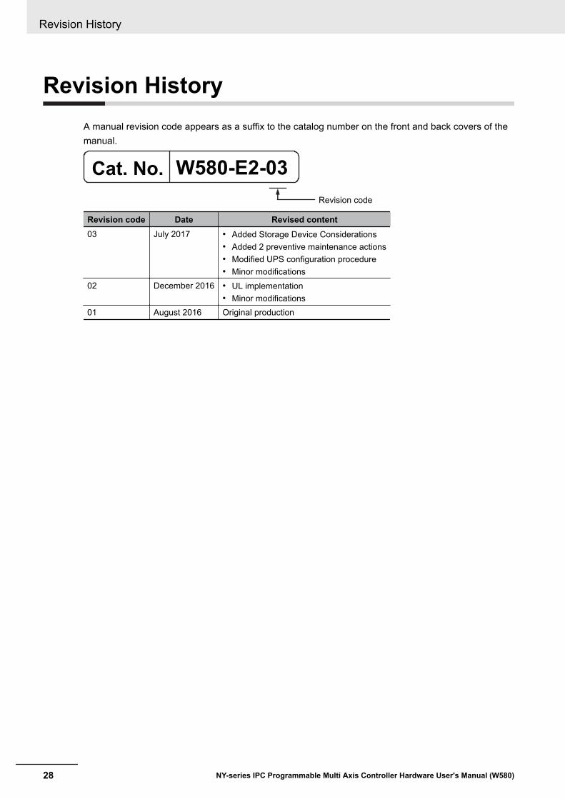
Revision HistoryA manual revision code appears as a suffix to the catalog number on the front and back covers of themanual.
W580-E2-03Cat. No.
Revision code
Revision code Date Revised content03 July 2017 • Added Storage Device Considerations
• Added 2 preventive maintenance actions• Modified UPS configuration procedure• Minor modifications
02 December 2016 • UL implementation• Minor modifications
01 August 2016 Original production
Revision History
28 NY-series IPC Programmable Multi Axis Controller Hardware User's Manual (W580)
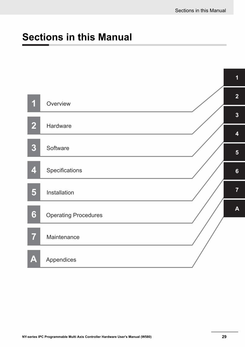
Sections in this Manual
Operating Procedures
Specifications
Installation
Software
Hardware
Overview1
2
3
4
5
6
1
2
3
4
6
5
1
7
7
Appendices
Maintenance
A
A
Sections in this Manual
29NY-series IPC Programmable Multi Axis Controller Hardware User's Manual (W580)

Sections in this Manual
30 NY-series IPC Programmable Multi Axis Controller Hardware User's Manual (W580)
1Overview
This section provides general information about the IPC Programmable Multi AxisController.
1-1 Intended Use ................................................................................................ 1 - 21-2 Hardware Features....................................................................................... 1 - 31-3 Software Features ........................................................................................ 1 - 41-4 ID Information Label..................................................................................... 1 - 5
1-4-1 Label with Controller License (Optional) ....................................................... 1 - 5
1-5 Product Configuration ................................................................................. 1 - 61-6 Industrial PC Platform Overview ................................................................ 1 - 7
1-6-1 Industrial Monitor ......................................................................................... 1 - 71-6-2 Industrial Box PC ......................................................................................... 1 - 8
1 - 1NY-series IPC Programmable Multi Axis Controller Hardware User's Manual (W580)
1
1-1 Intended UseThe IPC Programmable Multi Axis Controller (also indicated as Box PC) is an industrial-grade PC in-tended for use within factory automation environments. This Box PC simultaneously uses the standardWindows operating system and Linux running the Programmable Multi Axis Controller kernel to serveas a powerful PC based motion control platform. The Programmable Multi Axis Controller kernel offersall of the intelligence and capabilities of the IPC Programmable Multi Axis Controller. With its built-inmotion programs, software PLCs and basic I/O support, the Box PC offers complete machine logiccontrol over EtherCAT.The IPC Programmable Multi Axis Controller has a compact design that offers flexibility, expandabilityand easy maintenance for applications in factory automation environments.
1 Overview
1 - 2 NY-series IPC Programmable Multi Axis Controller Hardware User's Manual (W580)

1-2 Hardware FeaturesThe IPC Programmable Multi Axis Controller provides the following hardware features:• Compact design with two mounting orientation options
The Box PC has a compact design to minimize panel space while allowing for two mounting orienta-tions.
• Powerful CPUA powerful CPU provides high performance for various applications.
• Parallel Execution of Tasks with a Multi-core ProcessorWith a multi-core processor, the IPC Programmable Multi Axis Controller can execute the task andsystem services in parallel. This enables high-speed control of even large-scale devices.
• Easy access to storage devices and the PCI Express CardAdding or changing storage devices (HDD, SSD) and the PCI Express Card is fast and simple.
• DVI visual interfaceThe video interface for the Box PC is provided with a DVI connector for connection to a monitor.
• 3 Ethernet ports 1Gb/sThree ports support EtherCAT, EtherNet/IP, and Ethernet (for Windows) for interfacing with multiplenetwork types.
• EtherCAT Control Network SupportThe IPC Programmable Multi Axis Controller provides an EtherCAT master port for EtherCAT com-munications. EtherCAT is an advanced industrial network system that achieves faster, more-efficientcommunications. It is based on Ethernet. Each node achieves a short fixed communications cycletime by transmitting Ethernet frames at high speed.The standard-feature EtherCAT control network allows you to connect all of the devices required formachine control (e.g., I/O systems, Servo Drives, Inverters, and machine vision) to the same net-work.
• Support for EtherCAT Slave TerminalsYou can use EtherCAT Slave Terminals to save space. You can also flexibly build systems with thewide variety of NX Units.
• Achieving a Safety Subsystem on EtherCATYou can use NX-series Safety Control Units to integrate safety controls in a sequence and motioncontrol system as a subsystem on EtherCAT.
• Built-in I/OBuilt-in I/O for UPS status and Box PC shutdown control are provided.
• 4 USB ports2 USB2.0 ports and 2 USB3.0 ports are provided for connection to external USB devices such askeyboards, memory sticks, or other peripheral hardware.
• Built-in SD Memory Card slotAn SD Memory Card slot is provided for removable memory.
1 Overview
1 - 3NY-series IPC Programmable Multi Axis Controller Hardware User's Manual (W580)
1-2 Hardw
are Features
1
1-3 Software FeaturesThe IPC Programmable Multi Axis Controller provides the following software features:• Fast Multi-Axis Control
The Programmable Multi-Axis Controller is developed by Delta Tau Data Systems, Inc., a manufac-turer specializing in motion controllers. It allows for multi-axis control of up to 64 axes per unit (whenCK3E-1500 is used), and the fast control of 250 μs/8-axis and 500 μs/64-axis.
• CNC FunctionThe Controller has CNC functionality and supports G-code. This allows for high precision machiningon curved surfaces and lines.
• Constructing Systems with Greater FlexibilityPrograms can be written in G-code, C language, or PMAC script for the Controller. Such functiondesign flexibility allows you to create functions that are optimized for your equipment.Various EtherCAT-compatible products such as vision sensors and I/O as well as motion controlscan be connected, allowing you to construct custom systems for your equipment.
1 Overview
1 - 4 NY-series IPC Programmable Multi Axis Controller Hardware User's Manual (W580)
1-4 ID Information LabelThe ID information label contains relevant information about the IPC Programmable Multi Axis Control-ler.The following example will be different from your product label.
CUSTOM ID
Corporation Kyoto, 600-8530 JAPAN MADE IN THE NETHERLANDS
PRODUCT NAME
BA
G EF
C D
Item Name DescriptionA Product name The name of your productB Model *1 Model and configuration details
C Power rating Power rating detailsD Custom ID
(Optional)A custom ID [NYC£££-££££££££]Only for Industrial Monitors and Industrial Panel PCs with a custom logo *1.
E Standards and QRcode
The applicable standards and a QR code for OMRON internal use
F LOT number andserial number
Production details, consisting of:• The lot number of the IPC Programmable Multi Axis Controller in the format
DDMYY£.DDMYY with Month number 1 to 9 for January to September, X for October, Yfor November, and Z for December.£: For use by OMRON
• Serial number (4 digits)G MAC ADDRESS *2 • PORT 1: the MAC address of Ethernet port 1
• PORT 2: the MAC address of Ethernet port 2• PORT 3: the MAC address of Ethernet port 3
*1. Refer to 1-5 Product Configuration on page 1 - 6 for model details.*2. Refer to 4-2-4 Ethernet Connector Specifications on page 4 - 15 for Ethernet specifications.
Additional Information
Refer to 2-2-2 Back of the Industrial Box PC on page 2 - 6 for the ID label location.
1-4-1 Label with Controller License (Optional)This license label contains the license key for the Industrial PC with Programmable Multi Axis Control-ler.
IPC Programmable Multi Axis Controller license number
1 Overview
1 - 5NY-series IPC Programmable Multi Axis Controller Hardware User's Manual (W580)
1-4 ID Inform
ation Label
1
1-4-1 Label with C
ontroller License (Optional)

1-5 Product ConfigurationThis section provides an overview of the product configurations available for the IPC ProgrammableMulti Axis Controller.The product configuration is visible in the model-type that is mentioned on the ID information label ofthe product.The structure of the model-type is: NY£££-££££-£££££££££.Each item in the model-type has a specific meaning.
N Y
1 2 3 4 5 6 7 8 9 10 11 12 13 14 15 16 17
Item Description Option / Description1 Series name NY: NY-series Industrial PC Platform2 Controller specifications 5: "5" series: Large scale, high speed and high precision control
application3 Model type 1: Industrial Box PC4 Sequential number 2: Latest edition5 Function module A: IPC Programmable Multi Axis Controller6 Number of axes for motion con-
trol6: 128 axes
7 Additional Function SoftwareModule
0: ---
8 Reserved 0: ---9 Expansion slots 1: 1 PCIe slot10 Frame type X: No display (Industrial Box PC)11 Display size X: No display (Industrial Box PC)12 Operating system 2: Windows Embedded Standard 7 - 64 bit13 Processor 1: Intel® Core™ i7-4700EQ Processor
4th generation CPU with Fan Unit for active cooling14 Main memory 3: 8 GB Non-ECC15 Storage 9: 64 GB, SSD SLC16 Optional interface 1: RS-232C17 Logo X: No display (Industrial Box PC)
1 Overview
1 - 6 NY-series IPC Programmable Multi Axis Controller Hardware User's Manual (W580)
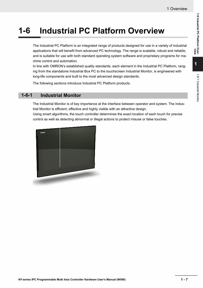
1-6 Industrial PC Platform OverviewThe Industrial PC Platform is an integrated range of products designed for use in a variety of industrialapplications that will benefit from advanced PC technology. The range is scalable, robust and reliable,and is suitable for use with both standard operating system software and proprietary programs for ma-chine control and automation.In line with OMRON’s established quality standards, each element in the Industrial PC Platform, rang-ing from the standalone Industrial Box PC to the touchscreen Industrial Monitor, is engineered withlong-life components and built to the most advanced design standards.
The following sections introduce Industrial PC Platform products.
1-6-1 Industrial MonitorThe Industrial Monitor is of key importance at the interface between operator and system. The Indus-trial Monitor is efficient, effective and highly visible with an attractive design.Using smart algorithms, the touch controller determines the exact location of each touch for precisecontrol as well as detecting abnormal or illegal actions to protect misuse or false touches.
1 Overview
1 - 7NY-series IPC Programmable Multi Axis Controller Hardware User's Manual (W580)
1-6 Industrial PC Platform
Over-
view
1
1-6-1 Industrial Monitor

1-6-2 Industrial Box PCThe Industrial Box PC is designed to meet the specific needs of the industrial environment. Designsimplification and future-proof architecture minimize the risk of failure. In addition, new PC featurescan be seamlessly incorporated, without the need for wholesale redesign.
1 Overview
1 - 8 NY-series IPC Programmable Multi Axis Controller Hardware User's Manual (W580)
2Hardware
This section provides an overview of the hardware of the IPC Programmable Multi Ax-is Controller.
2-1 System Configuration.................................................................................. 2 - 32-2 Component Names and Functions............................................................. 2 - 4
2-2-1 Front and Top of the Industrial Box PC......................................................... 2 - 42-2-2 Back of the Industrial Box PC ....................................................................... 2 - 6
2-3 LED Indicators.............................................................................................. 2 - 72-3-1 PWR LED Indicator....................................................................................... 2 - 72-3-2 ERR LED Indicator ....................................................................................... 2 - 82-3-3 HDD LED Indicator ....................................................................................... 2 - 82-3-4 RUN LED Indicator ....................................................................................... 2 - 8
2-4 Power Button................................................................................................ 2 - 92-5 Drive Bays................................................................................................... 2 - 102-6 SD Memory Card Slot ................................................................................ 2 - 112-7 PCIe Card Slot ............................................................................................ 2 - 122-8 Connectors ................................................................................................. 2 - 13
2-8-1 Power Connector ........................................................................................ 2 - 132-8-2 I/O Connector ............................................................................................. 2 - 132-8-3 USB Connectors ......................................................................................... 2 - 142-8-4 Ethernet Connectors................................................................................... 2 - 152-8-5 DVI Connector ............................................................................................ 2 - 152-8-6 RS-232C Connector (Optional)................................................................... 2 - 16
2-9 Spare Parts ................................................................................................. 2 - 172-9-1 Battery ........................................................................................................ 2 - 172-9-2 Fan Unit ...................................................................................................... 2 - 172-9-3 Accessory Kit .............................................................................................. 2 - 18
2-10 Optional Hardware ..................................................................................... 2 - 192-10-1 Mounting Brackets ...................................................................................... 2 - 192-10-2 SD Memory Cards ...................................................................................... 2 - 192-10-3 USB Flash Drives ....................................................................................... 2 - 202-10-4 Storage Devices ......................................................................................... 2 - 202-10-5 DVI Cables.................................................................................................. 2 - 212-10-6 USB Type-A to USB Type-B Cables ........................................................... 2 - 212-10-7 Industrial Monitor ....................................................................................... 2 - 222-10-8 Power Supply.............................................................................................. 2 - 222-10-9 UPS ............................................................................................................ 2 - 23
2 - 1NY-series IPC Programmable Multi Axis Controller Hardware User's Manual (W580)
2
2-10-10 UPS Communication Cable ........................................................................ 2 - 232-10-11 Recommended EtherCAT Cables............................................................... 2 - 24
2 Hardware
2 - 2 NY-series IPC Programmable Multi Axis Controller Hardware User's Manual (W580)
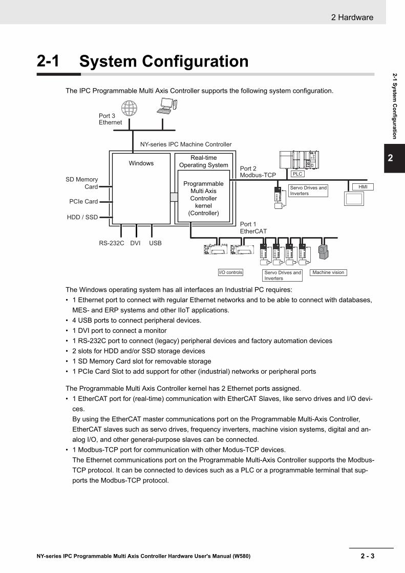
2-1 System ConfigurationThe IPC Programmable Multi Axis Controller supports the following system configuration.
Real-time
Operating System
NY-series IPC Machine Controller
EtherCAT
Machine visionServo Drives and
Inverters
I/O controls
Modbus-TCP
Ethernet
PLC
HMIProgrammable
Multi Axis
Controller
kernel
(Controller)
Windows
SD Memory
Card
PCIe Card
HDD / SSD
RS-232C DVI USB
Port 1
Port 2
Port 3
Servo Drives and
Inverters
The Windows operating system has all interfaces an Industrial PC requires:• 1 Ethernet port to connect with regular Ethernet networks and to be able to connect with databases,
MES- and ERP systems and other IIoT applications.• 4 USB ports to connect peripheral devices.• 1 DVI port to connect a monitor• 1 RS-232C port to connect (legacy) peripheral devices and factory automation devices• 2 slots for HDD and/or SSD storage devices• 1 SD Memory Card slot for removable storage• 1 PCIe Card Slot to add support for other (industrial) networks or peripheral ports
The Programmable Multi Axis Controller kernel has 2 Ethernet ports assigned.• 1 EtherCAT port for (real-time) communication with EtherCAT Slaves, like servo drives and I/O devi-
ces.By using the EtherCAT master communications port on the Programmable Multi-Axis Controller,EtherCAT slaves such as servo drives, frequency inverters, machine vision systems, digital and an-alog I/O, and other general-purpose slaves can be connected.
• 1 Modbus-TCP port for communication with other Modus-TCP devices.The Ethernet communications port on the Programmable Multi-Axis Controller supports the Modbus-TCP protocol. It can be connected to devices such as a PLC or a programmable terminal that sup-ports the Modbus-TCP protocol.
2 Hardware
2 - 3NY-series IPC Programmable Multi Axis Controller Hardware User's Manual (W580)
2-1 System C
onfiguration
2

2-2 Component Names and FunctionsThis section shows views of the IPC Programmable Multi Axis Controller with information about allitems.
2-2-1 Front and Top of the Industrial Box PCThis section shows the component names and functions for the front and top of the Box PC.
A
D
I
L
K
J
H
G
F
E
B
C
M
Item Name DescriptionA Cover Provides access to:
• The battery• The fans (only for Box PCs that have active cooling)• The battery replacement date• The license key for the operating system (optional)
2 Hardware
2 - 4 NY-series IPC Programmable Multi Axis Controller Hardware User's Manual (W580)
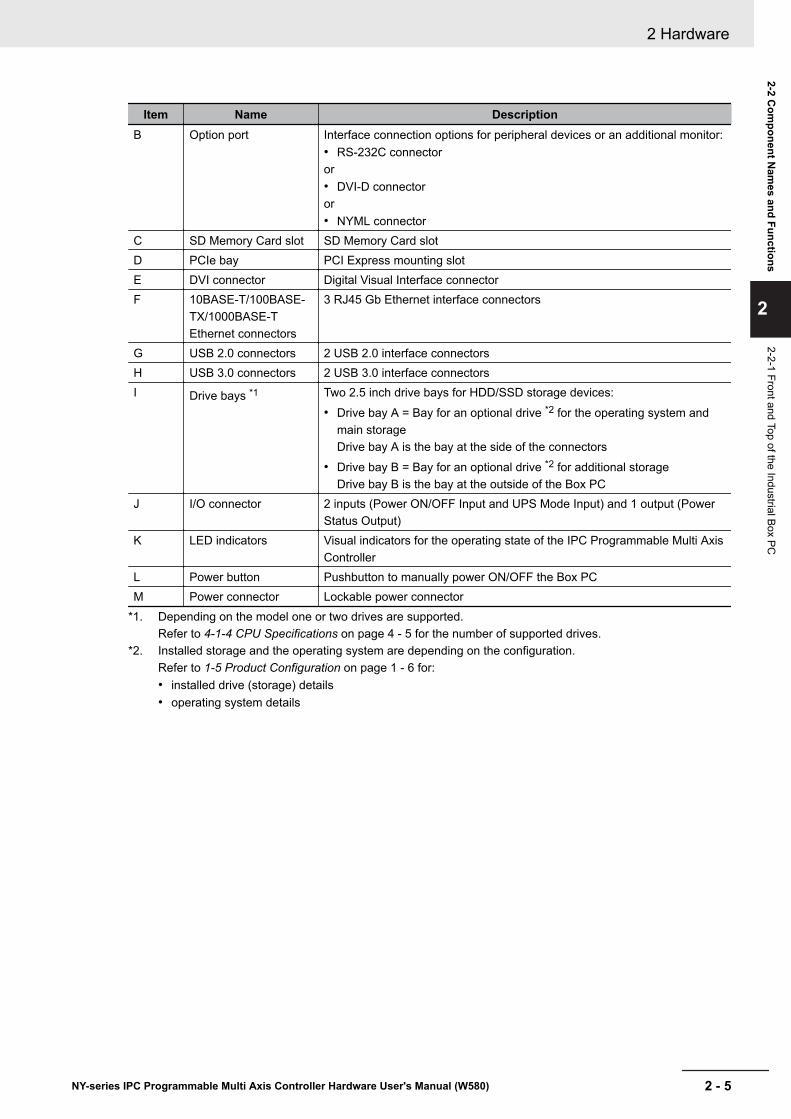
Item Name DescriptionB Option port Interface connection options for peripheral devices or an additional monitor:
• RS-232C connectoror• DVI-D connectoror• NYML connector
C SD Memory Card slot SD Memory Card slotD PCIe bay PCI Express mounting slotE DVI connector Digital Visual Interface connectorF 10BASE-T/100BASE-
TX/1000BASE-TEthernet connectors
3 RJ45 Gb Ethernet interface connectors
G USB 2.0 connectors 2 USB 2.0 interface connectorsH USB 3.0 connectors 2 USB 3.0 interface connectorsI Drive bays *1 Two 2.5 inch drive bays for HDD/SSD storage devices:
• Drive bay A = Bay for an optional drive *2 for the operating system andmain storageDrive bay A is the bay at the side of the connectors
• Drive bay B = Bay for an optional drive *2 for additional storageDrive bay B is the bay at the outside of the Box PC
J I/O connector 2 inputs (Power ON/OFF Input and UPS Mode Input) and 1 output (PowerStatus Output)
K LED indicators Visual indicators for the operating state of the IPC Programmable Multi AxisController
L Power button Pushbutton to manually power ON/OFF the Box PCM Power connector Lockable power connector
*1. Depending on the model one or two drives are supported.Refer to 4-1-4 CPU Specifications on page 4 - 5 for the number of supported drives.
*2. Installed storage and the operating system are depending on the configuration.Refer to 1-5 Product Configuration on page 1 - 6 for:• installed drive (storage) details• operating system details
2 Hardware
2 - 5NY-series IPC Programmable Multi Axis Controller Hardware User's Manual (W580)
2-2 Com
ponent Nam
es and Functions
2
2-2-1 Front and Top of the Industrial Box PC

2-2-2 Back of the Industrial Box PCThis section shows the component names and functions for the back of the Industrial Box PC.
A B
Item Name DescriptionA ID information label Label containing Model ID., LOT No. and other product specific information.
*1
B License label Optional label containing the license number. Only available on IndustrialPC with Programmable Multi Axis Controller models. *1 *2
*1. Refer to 1-4 ID Information Label on page 1 - 5 for label details.*2. Refer to 1-5 Product Configuration on page 1 - 6 for configuration details.
2 Hardware
2 - 6 NY-series IPC Programmable Multi Axis Controller Hardware User's Manual (W580)
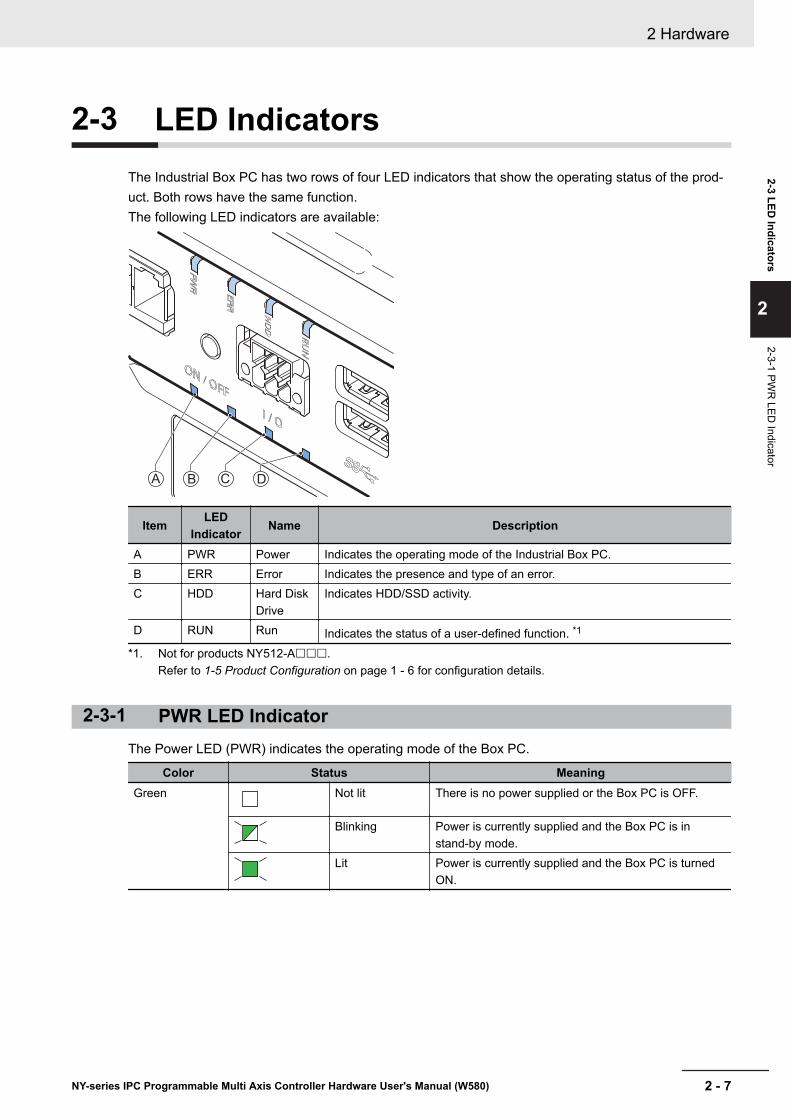
2-3 LED IndicatorsThe Industrial Box PC has two rows of four LED indicators that show the operating status of the prod-uct. Both rows have the same function.The following LED indicators are available:
A B C D
Item LEDIndicator Name Description
A PWR Power Indicates the operating mode of the Industrial Box PC.B ERR Error Indicates the presence and type of an error.C HDD Hard Disk
DriveIndicates HDD/SSD activity.
D RUN Run Indicates the status of a user-defined function. *1
*1. Not for products NY512-A£££.Refer to 1-5 Product Configuration on page 1 - 6 for configuration details.
2-3-1 PWR LED IndicatorThe Power LED (PWR) indicates the operating mode of the Box PC.
Color Status MeaningGreen Not lit There is no power supplied or the Box PC is OFF.
Blinking Power is currently supplied and the Box PC is instand-by mode.
Lit Power is currently supplied and the Box PC is turnedON.
2 Hardware
2 - 7NY-series IPC Programmable Multi Axis Controller Hardware User's Manual (W580)
2-3 LED Indicators
2
2-3-1 PWR
LED Indicator
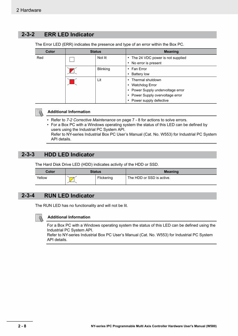
2-3-2 ERR LED IndicatorThe Error LED (ERR) indicates the presence and type of an error within the Box PC.
Color Status MeaningRed Not lit • The 24 VDC power is not supplied
• No error is presentBlinking • Fan Error
• Battery lowLit • Thermal shutdown
• Watchdog Error• Power Supply undervoltage error• Power Supply overvoltage error• Power supply defective
Additional Information
• Refer to 7-2 Corrective Maintenance on page 7 - 8 for actions to solve errors.• For a Box PC with a Windows operating system the status of this LED can be defined by
users using the Industrial PC System API.Refer to NY-series Industrial Box PC User’s Manual (Cat. No. W553) for Industrial PC SystemAPI details.
2-3-3 HDD LED IndicatorThe Hard Disk Drive LED (HDD) indicates activity of the HDD or SSD.
Color Status MeaningYellow Flickering The HDD or SSD is active.
2-3-4 RUN LED IndicatorThe RUN LED has no functionality and will not be lit.
Additional Information
For a Box PC with a Windows operating system the status of this LED can be defined using theIndustrial PC System API.Refer to NY-series Industrial Box PC User’s Manual (Cat. No. W553) for Industrial PC SystemAPI details.
2 Hardware
2 - 8 NY-series IPC Programmable Multi Axis Controller Hardware User's Manual (W580)

2-4 Power ButtonThe power button is used to manually switch the Box PC ON and OFF.
Additional Information
• Refer to 6-1 Power ON on page 6 - 2 for ON details.• Refer to 6-2 Power OFF on page 6 - 3 for OFF details.
2 Hardware
2 - 9NY-series IPC Programmable Multi Axis Controller Hardware User's Manual (W580)
2-4 Power B
utton
2
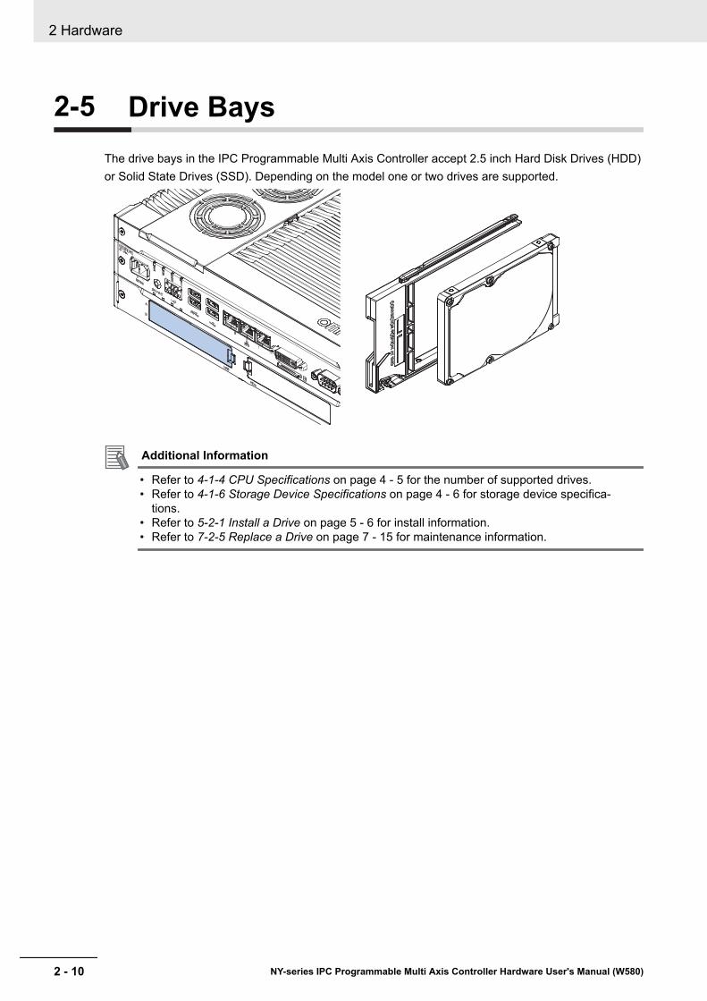
2-5 Drive BaysThe drive bays in the IPC Programmable Multi Axis Controller accept 2.5 inch Hard Disk Drives (HDD)or Solid State Drives (SSD). Depending on the model one or two drives are supported.
Additional Information
• Refer to 4-1-4 CPU Specifications on page 4 - 5 for the number of supported drives.• Refer to 4-1-6 Storage Device Specifications on page 4 - 6 for storage device specifica-
tions.• Refer to 5-2-1 Install a Drive on page 5 - 6 for install information.• Refer to 7-2-5 Replace a Drive on page 7 - 15 for maintenance information.
2 Hardware
2 - 10 NY-series IPC Programmable Multi Axis Controller Hardware User's Manual (W580)

2-6 SD Memory Card SlotThe SD Memory Card slot on the IPC Programmable Multi Axis Controller accepts SD Memory Cardswith the following specifications.• SDHC type (SD 2.0 specification)• Up to 32 GB capacity
Additional Information
Refer to 2-10-2 SD Memory Cards on page 2 - 19 for SD Memory Card details.
2 Hardware
2 - 11NY-series IPC Programmable Multi Axis Controller Hardware User's Manual (W580)
2-6 SD M
emory C
ard Slot
2

2-7 PCIe Card SlotThe PCI Express (PCIe) Card slot of the IPC Programmable Multi Axis Controller accepts variousPCIe Cards for specific hardware needs.
The PCIe Card connectors are available behind the cover A and the PCIe Card is mounted in the
PCIe drawer B .
A B
Additional Information
• Refer to 4-1-7 PCIe Card Specifications on page 4 - 7 for specifications.• Refer to 5-2-2 Install the PCIe Card on page 5 - 10 for install information.• Refer to 7-2-6 Replace the PCIe Card on page 7 - 20 for maintenance information.
2 Hardware
2 - 12 NY-series IPC Programmable Multi Axis Controller Hardware User's Manual (W580)
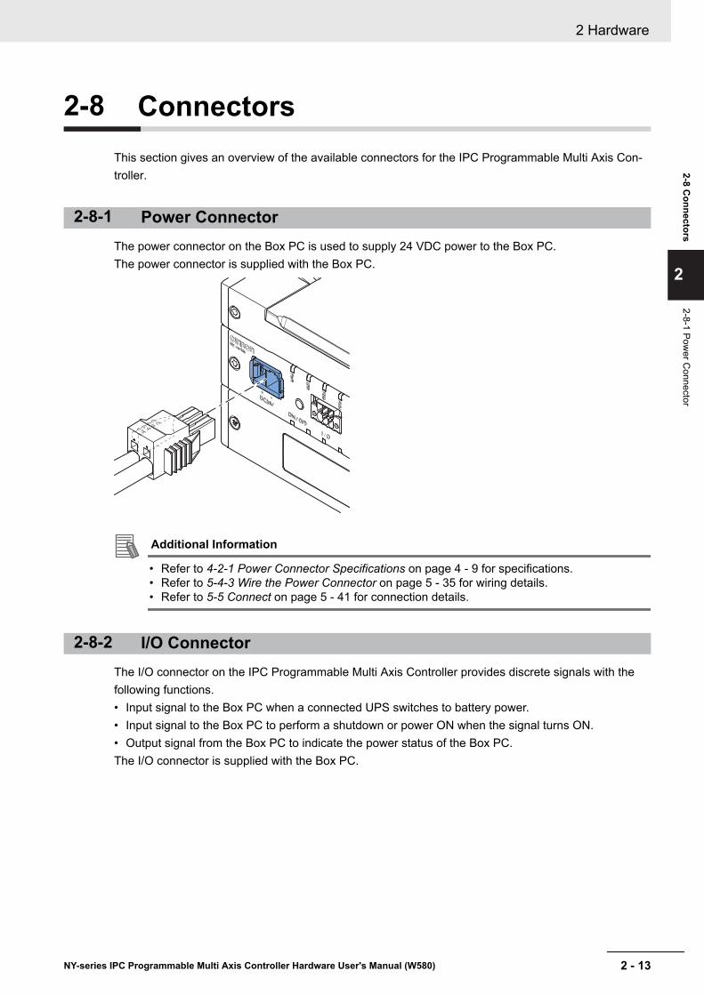
2-8 ConnectorsThis section gives an overview of the available connectors for the IPC Programmable Multi Axis Con-troller.
2-8-1 Power ConnectorThe power connector on the Box PC is used to supply 24 VDC power to the Box PC.The power connector is supplied with the Box PC.
Additional Information
• Refer to 4-2-1 Power Connector Specifications on page 4 - 9 for specifications.• Refer to 5-4-3 Wire the Power Connector on page 5 - 35 for wiring details.• Refer to 5-5 Connect on page 5 - 41 for connection details.
2-8-2 I/O ConnectorThe I/O connector on the IPC Programmable Multi Axis Controller provides discrete signals with thefollowing functions.• Input signal to the Box PC when a connected UPS switches to battery power.• Input signal to the Box PC to perform a shutdown or power ON when the signal turns ON.• Output signal from the Box PC to indicate the power status of the Box PC.The I/O connector is supplied with the Box PC.
2 Hardware
2 - 13NY-series IPC Programmable Multi Axis Controller Hardware User's Manual (W580)
2-8 Connectors
2
2-8-1 Power C
onnector
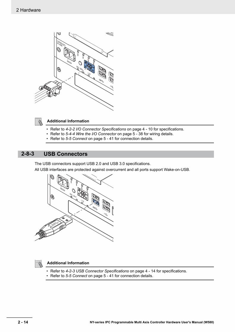
Additional Information
• Refer to 4-2-2 I/O Connector Specifications on page 4 - 10 for specifications.• Refer to 5-4-4 Wire the I/O Connector on page 5 - 38 for wiring details.• Refer to 5-5 Connect on page 5 - 41 for connection details.
2-8-3 USB ConnectorsThe USB connectors support USB 2.0 and USB 3.0 specifications.All USB interfaces are protected against overcurrent and all ports support Wake-on-USB.
Additional Information
• Refer to 4-2-3 USB Connector Specifications on page 4 - 14 for specifications.• Refer to 5-5 Connect on page 5 - 41 for connection details.
2 Hardware
2 - 14 NY-series IPC Programmable Multi Axis Controller Hardware User's Manual (W580)
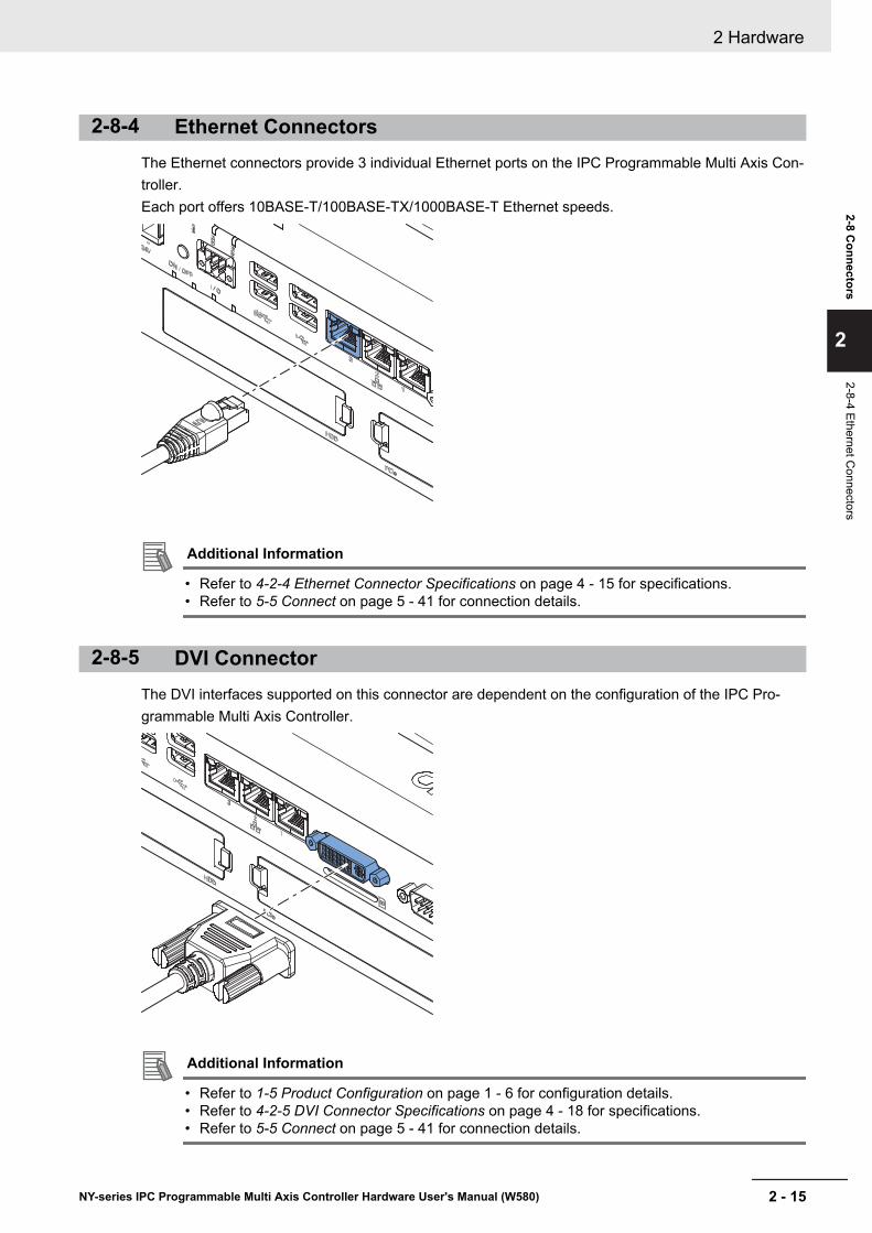
2-8-4 Ethernet ConnectorsThe Ethernet connectors provide 3 individual Ethernet ports on the IPC Programmable Multi Axis Con-troller.Each port offers 10BASE-T/100BASE-TX/1000BASE-T Ethernet speeds.
Additional Information
• Refer to 4-2-4 Ethernet Connector Specifications on page 4 - 15 for specifications.• Refer to 5-5 Connect on page 5 - 41 for connection details.
2-8-5 DVI ConnectorThe DVI interfaces supported on this connector are dependent on the configuration of the IPC Pro-grammable Multi Axis Controller.
Additional Information
• Refer to 1-5 Product Configuration on page 1 - 6 for configuration details.• Refer to 4-2-5 DVI Connector Specifications on page 4 - 18 for specifications.• Refer to 5-5 Connect on page 5 - 41 for connection details.
2 Hardware
2 - 15NY-series IPC Programmable Multi Axis Controller Hardware User's Manual (W580)
2-8 Connectors
2
2-8-4 Ethernet Connectors
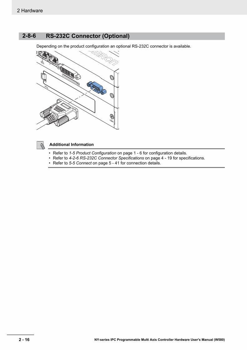
2-8-6 RS-232C Connector (Optional)Depending on the product configuration an optional RS-232C connector is available.
Additional Information
• Refer to 1-5 Product Configuration on page 1 - 6 for configuration details.• Refer to 4-2-6 RS-232C Connector Specifications on page 4 - 19 for specifications.• Refer to 5-5 Connect on page 5 - 41 for connection details.
2 Hardware
2 - 16 NY-series IPC Programmable Multi Axis Controller Hardware User's Manual (W580)
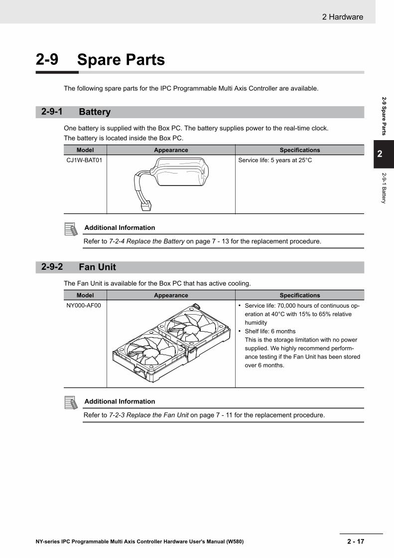
2-9 Spare PartsThe following spare parts for the IPC Programmable Multi Axis Controller are available.
2-9-1 BatteryOne battery is supplied with the Box PC. The battery supplies power to the real-time clock.The battery is located inside the Box PC.
Model Appearance SpecificationsCJ1W-BAT01 Service life: 5 years at 25°C
Additional Information
Refer to 7-2-4 Replace the Battery on page 7 - 13 for the replacement procedure.
2-9-2 Fan UnitThe Fan Unit is available for the Box PC that has active cooling.
Model Appearance SpecificationsNY000-AF00 • Service life: 70,000 hours of continuous op-
eration at 40°C with 15% to 65% relativehumidity
• Shelf life: 6 monthsThis is the storage limitation with no powersupplied. We highly recommend perform-ance testing if the Fan Unit has been storedover 6 months.
Additional Information
Refer to 7-2-3 Replace the Fan Unit on page 7 - 11 for the replacement procedure.
2 Hardware
2 - 17NY-series IPC Programmable Multi Axis Controller Hardware User's Manual (W580)
2-9 Spare Parts
2
2-9-1 Battery
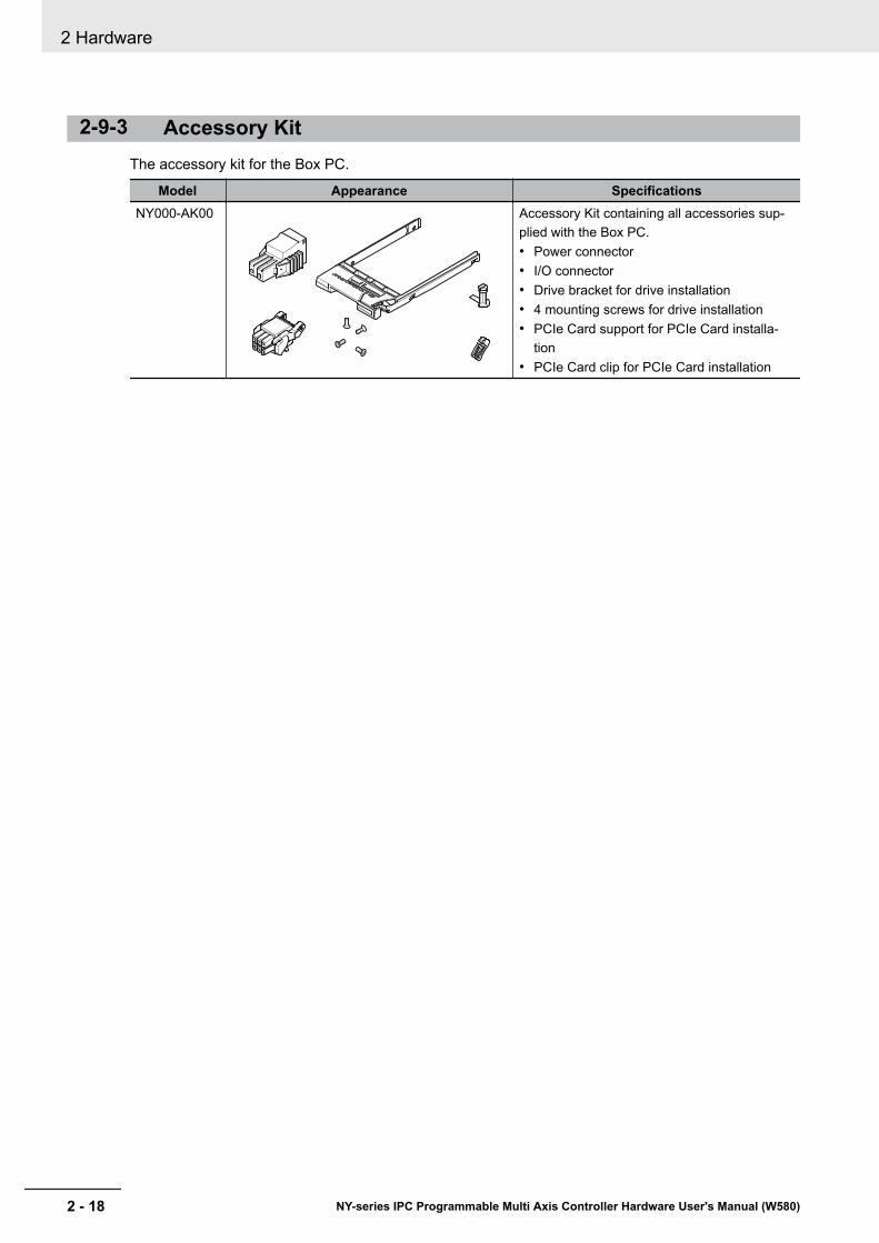
2-9-3 Accessory KitThe accessory kit for the Box PC.
Model Appearance SpecificationsNY000-AK00 Accessory Kit containing all accessories sup-
plied with the Box PC.• Power connector• I/O connector• Drive bracket for drive installation• 4 mounting screws for drive installation• PCIe Card support for PCIe Card installa-
tion• PCIe Card clip for PCIe Card installation
2 Hardware
2 - 18 NY-series IPC Programmable Multi Axis Controller Hardware User's Manual (W580)
2-10 Optional HardwareThe following optional hardware is available for the IPC Programmable Multi Axis Controller.
2-10-1 Mounting BracketsMounting brackets details are provided below.
Model Appearance Bracket typeNY000-AB00 Book mount
NY000-AB01 Wall mount
2-10-2 SD Memory CardsSD Memory Card details are provided below.OMRON is not responsible for the operation, performance or write life of any other brand of SD Memo-ry Card.
Model Appearance Card type Capacity FormatHMC-SD291 SD Card 2 GB FAT16HMC-SD491 SDHC Card 4 GB FAT32
2 Hardware
2 - 19NY-series IPC Programmable Multi Axis Controller Hardware User's Manual (W580)
2-10 Optional H
ardware
2
2-10-1 Mounting Brackets
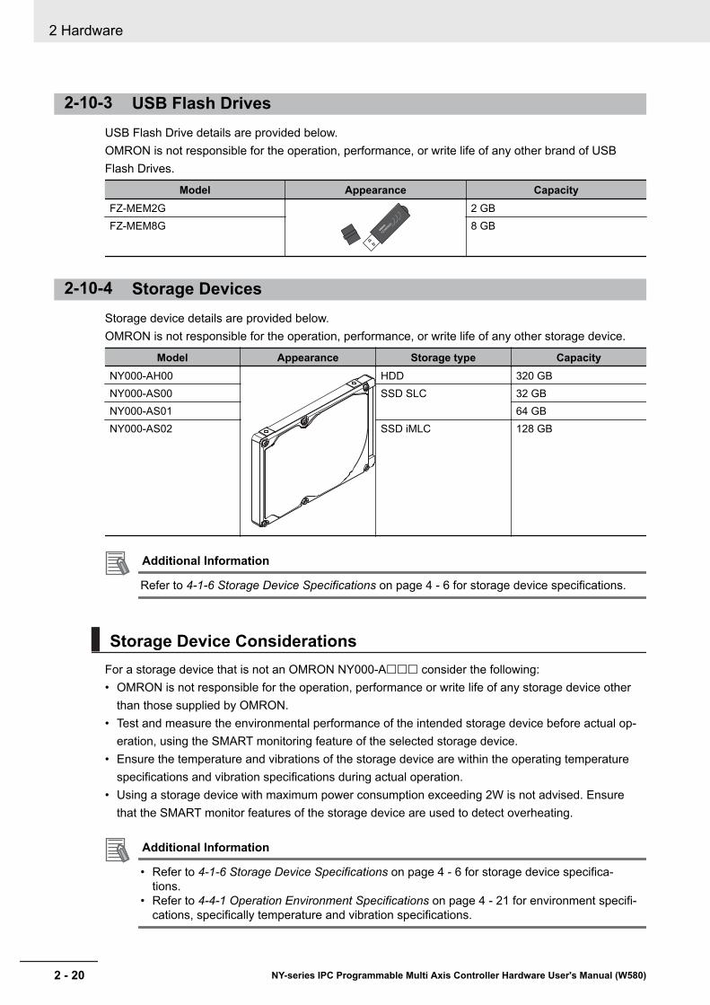
2-10-3 USB Flash DrivesUSB Flash Drive details are provided below.OMRON is not responsible for the operation, performance, or write life of any other brand of USBFlash Drives.
Model Appearance CapacityFZ-MEM2G
FZ-MEM2G
2 GBFZ-MEM8G 8 GB
2-10-4 Storage DevicesStorage device details are provided below. OMRON is not responsible for the operation, performance, or write life of any other storage device.
Model Appearance Storage type CapacityNY000-AH00 HDD 320 GBNY000-AS00 SSD SLC 32 GBNY000-AS01 64 GBNY000-AS02 SSD iMLC 128 GB
Additional Information
Refer to 4-1-6 Storage Device Specifications on page 4 - 6 for storage device specifications.
Storage Device ConsiderationsFor a storage device that is not an OMRON NY000-A£££ consider the following:• OMRON is not responsible for the operation, performance or write life of any storage device other
than those supplied by OMRON.• Test and measure the environmental performance of the intended storage device before actual op-
eration, using the SMART monitoring feature of the selected storage device.• Ensure the temperature and vibrations of the storage device are within the operating temperature
specifications and vibration specifications during actual operation.• Using a storage device with maximum power consumption exceeding 2W is not advised. Ensure
that the SMART monitor features of the storage device are used to detect overheating.
Additional Information
• Refer to 4-1-6 Storage Device Specifications on page 4 - 6 for storage device specifica-tions.
• Refer to 4-4-1 Operation Environment Specifications on page 4 - 21 for environment specifi-cations, specifically temperature and vibration specifications.
2 Hardware
2 - 20 NY-series IPC Programmable Multi Axis Controller Hardware User's Manual (W580)
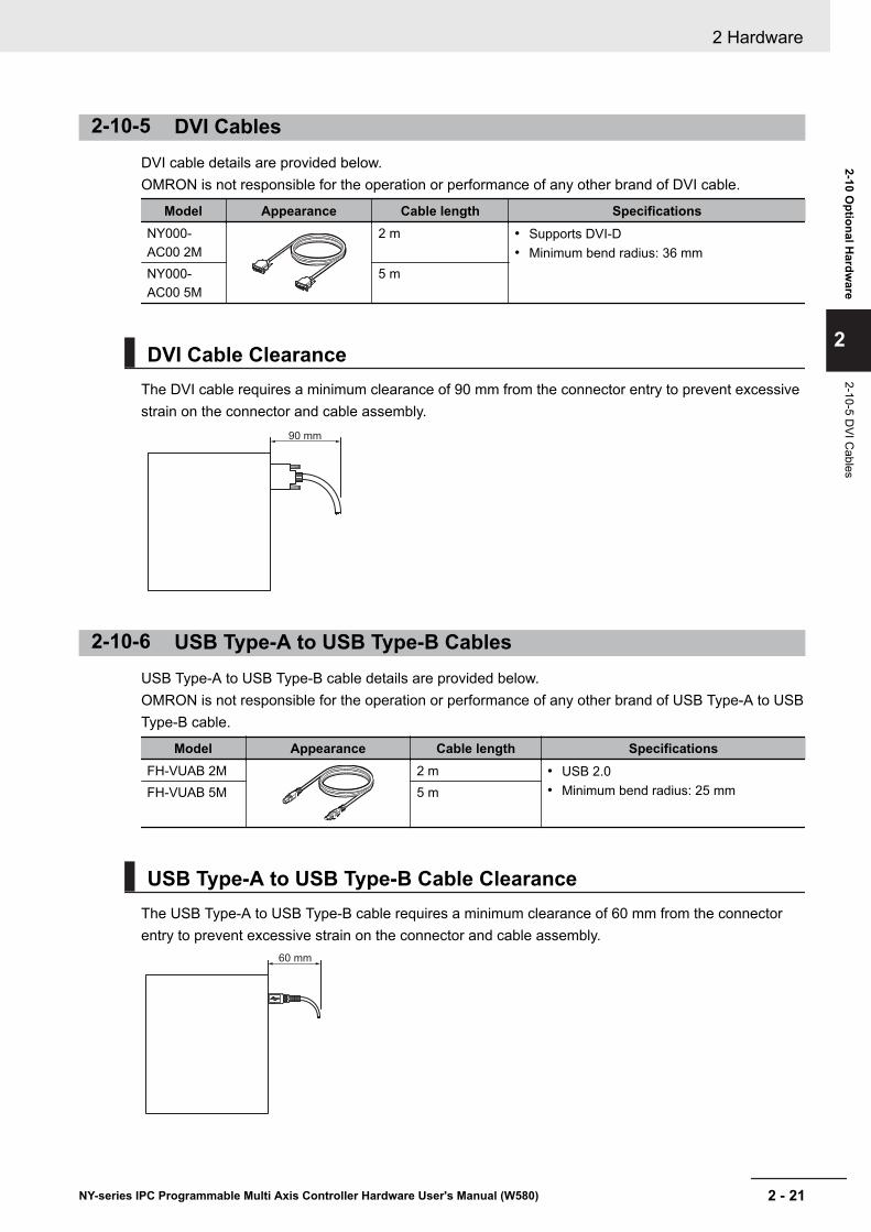
2-10-5 DVI CablesDVI cable details are provided below.OMRON is not responsible for the operation or performance of any other brand of DVI cable.
Model Appearance Cable length SpecificationsNY000-AC00 2M
2 m • Supports DVI-D• Minimum bend radius: 36 mm
NY000-AC00 5M
5 m
DVI Cable ClearanceThe DVI cable requires a minimum clearance of 90 mm from the connector entry to prevent excessivestrain on the connector and cable assembly.
90 mm
2-10-6 USB Type-A to USB Type-B CablesUSB Type-A to USB Type-B cable details are provided below.OMRON is not responsible for the operation or performance of any other brand of USB Type-A to USBType-B cable.
Model Appearance Cable length SpecificationsFH-VUAB 2M 2 m • USB 2.0
• Minimum bend radius: 25 mmFH-VUAB 5M 5 m
USB Type-A to USB Type-B Cable ClearanceThe USB Type-A to USB Type-B cable requires a minimum clearance of 60 mm from the connectorentry to prevent excessive strain on the connector and cable assembly.
60 mm
2 Hardware
2 - 21NY-series IPC Programmable Multi Axis Controller Hardware User's Manual (W580)
2-10 Optional H
ardware
2
2-10-5 DVI C
ables
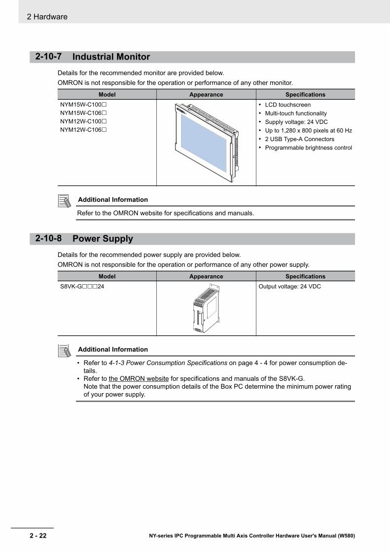
2-10-7 Industrial MonitorDetails for the recommended monitor are provided below.OMRON is not responsible for the operation or performance of any other monitor.
Model Appearance SpecificationsNYM15W-C100£NYM15W-C106£NYM12W-C100£NYM12W-C106£
• LCD touchscreen• Multi-touch functionality• Supply voltage: 24 VDC• Up to 1,280 x 800 pixels at 60 Hz• 2 USB Type-A Connectors• Programmable brightness control
Additional Information
Refer to the OMRON website for specifications and manuals.
2-10-8 Power SupplyDetails for the recommended power supply are provided below.OMRON is not responsible for the operation or performance of any other power supply.
Model Appearance SpecificationsS8VK-G£££24 Output voltage: 24 VDC
Additional Information
• Refer to 4-1-3 Power Consumption Specifications on page 4 - 4 for power consumption de-tails.
• Refer to the OMRON website for specifications and manuals of the S8VK-G.Note that the power consumption details of the Box PC determine the minimum power ratingof your power supply.
2 Hardware
2 - 22 NY-series IPC Programmable Multi Axis Controller Hardware User's Manual (W580)
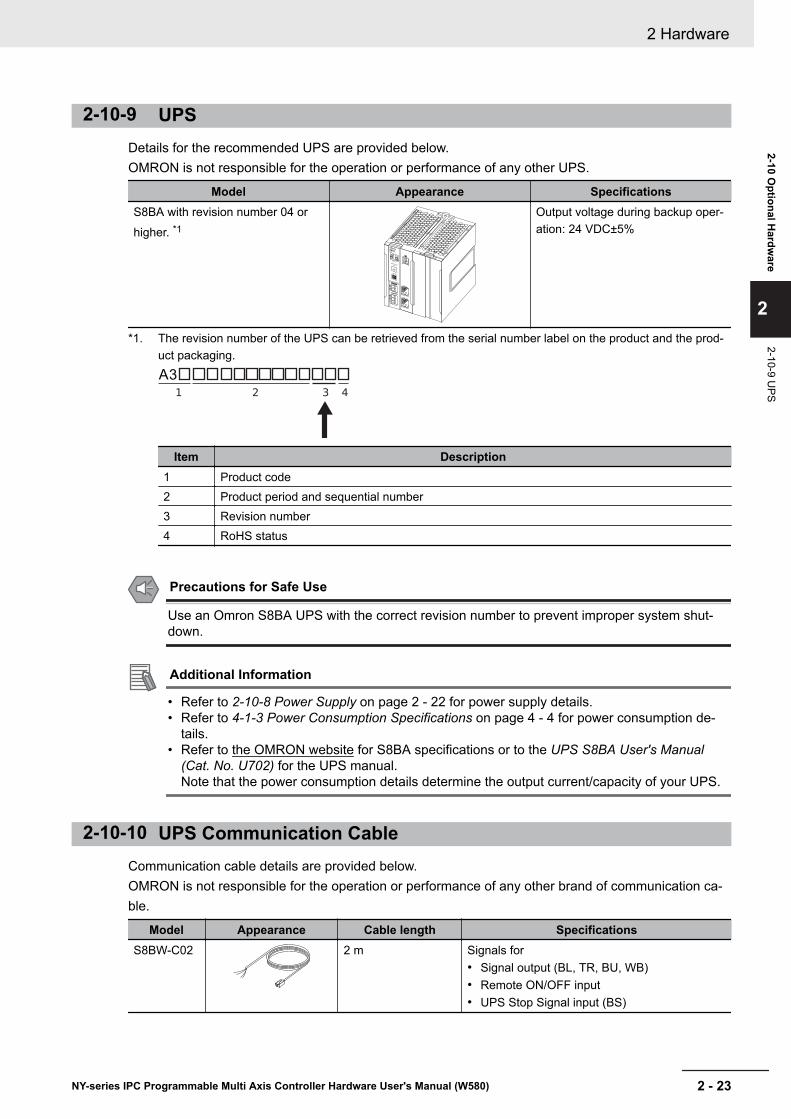
2-10-9 UPSDetails for the recommended UPS are provided below.OMRON is not responsible for the operation or performance of any other UPS.
Model Appearance SpecificationsS8BA with revision number 04 orhigher. *1
Output voltage during backup oper-ation: 24 VDC±5%
*1. The revision number of the UPS can be retrieved from the serial number label on the product and the prod-uct packaging.A3
Item Description1 Product code2 Product period and sequential number3 Revision number4 RoHS status
Precautions for Safe Use
Use an Omron S8BA UPS with the correct revision number to prevent improper system shut-down.
Additional Information
• Refer to 2-10-8 Power Supply on page 2 - 22 for power supply details.• Refer to 4-1-3 Power Consumption Specifications on page 4 - 4 for power consumption de-
tails.• Refer to the OMRON website for S8BA specifications or to the UPS S8BA User's Manual
(Cat. No. U702) for the UPS manual.Note that the power consumption details determine the output current/capacity of your UPS.
2-10-10 UPS Communication CableCommunication cable details are provided below.OMRON is not responsible for the operation or performance of any other brand of communication ca-ble.
Model Appearance Cable length SpecificationsS8BW-C02 2 m Signals for
• Signal output (BL, TR, BU, WB)• Remote ON/OFF input• UPS Stop Signal input (BS)
2 Hardware
2 - 23NY-series IPC Programmable Multi Axis Controller Hardware User's Manual (W580)
2-10 Optional H
ardware
2
2-10-9 UPS
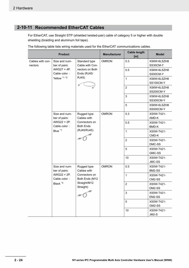
2-10-11 Recommended EtherCAT CablesFor EtherCAT, use Straight STP (shielded twisted-pair) cable of category 5 or higher with doubleshielding (braiding and aluminum foil tape).
The following table lists wiring materials used for the EtherCAT communications cables.
Product Manufacturer Cable length[m] Model
Cables with con-nectors
Size and num-ber of pairs:AWG27 × 4P.Cable color:Yellow *1 *2
Standard typeCable with Con-nectors on BothEnds (RJ45/RJ45)
OMRON 0.3 XS6W-6LSZH8SS30CM-Y
0.5 XS6W-6LSZH8SS50CM-Y
1 XS6W-6LSZH8SS100CM-Y
2 XS6W-6LSZH8SS200CM-Y
3 XS6W-6LSZH8SS300CM-Y
5 XS6W-6LSZH8SS500CM-Y
Size and num-ber of pairs:AWG22 × 2P.Cable color:Blue *1
Rugged typeCables withConnectors onBoth Ends(RJ45/RJ45)
OMRON 0.3 XS5W-T421-AMD-K
0.5 XS5W-T421-BMD-K
1 XS5W-T421-CMD-K
2 XS5W-T421-DMC-SS
5 XS5W-T421-GMC-SS
10 XS5W-T421-JMC-SS
Size and num-ber of pairs:AWG22 × 2P.Cable color:Black *3
Rugged typeCables withConnectors onBoth Ends (M12Straight/M12Straight)
OMRON 0.5 XS5W-T421-BM2-SS
1 XS5W-T421-CM2-SS
2 XS5W-T421-DM2-SS
3 XS5W-T421-EM2-SS
5 XS5W-T421-GM2-SS
10 XS5W-T421-JM2-S
2 Hardware
2 - 24 NY-series IPC Programmable Multi Axis Controller Hardware User's Manual (W580)
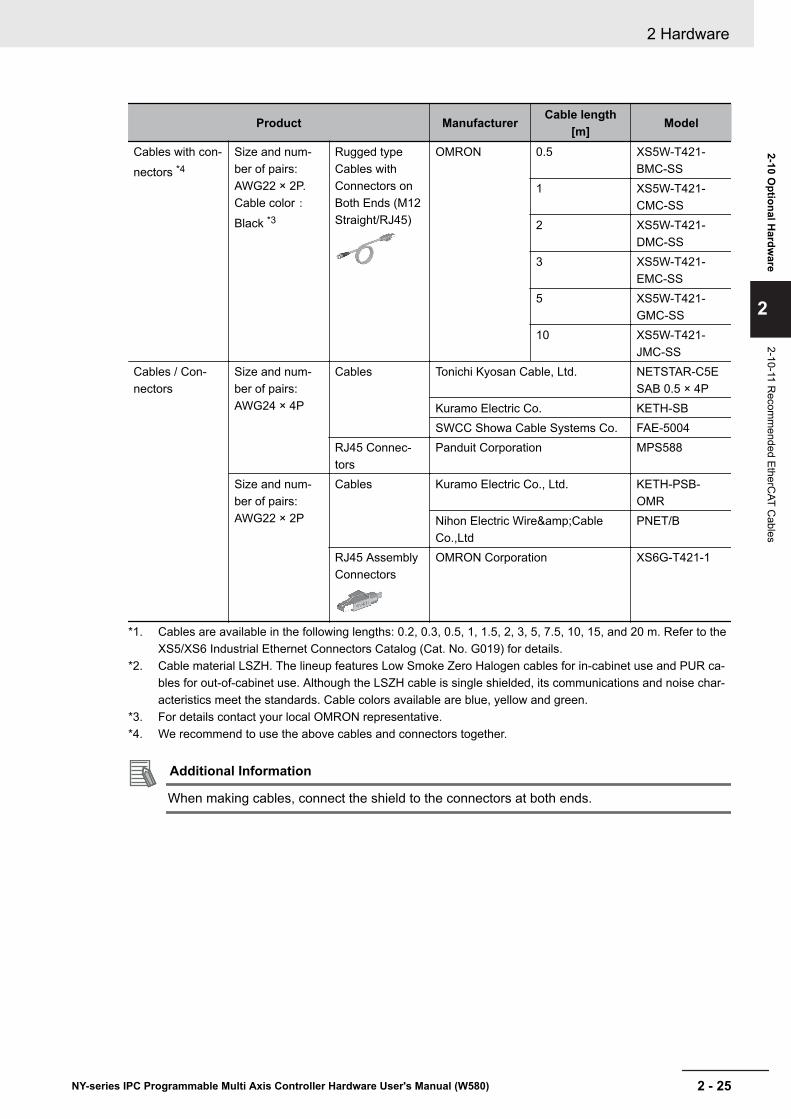
Product Manufacturer Cable length[m] Model
Cables with con-nectors *4
Size and num-ber of pairs:AWG22 × 2P.Cable color:Black *3
Rugged typeCables withConnectors onBoth Ends (M12Straight/RJ45)
OMRON 0.5 XS5W-T421-BMC-SS
1 XS5W-T421-CMC-SS
2 XS5W-T421-DMC-SS
3 XS5W-T421-EMC-SS
5 XS5W-T421-GMC-SS
10 XS5W-T421-JMC-SS
Cables / Con-nectors
Size and num-ber of pairs:AWG24 × 4P
Cables Tonichi Kyosan Cable, Ltd. NETSTAR-C5ESAB 0.5 × 4P
Kuramo Electric Co. KETH-SBSWCC Showa Cable Systems Co. FAE-5004
RJ45 Connec-tors
Panduit Corporation MPS588
Size and num-ber of pairs:AWG22 × 2P
Cables Kuramo Electric Co., Ltd. KETH-PSB-OMR
Nihon Electric Wire&CableCo.,Ltd
PNET/B
RJ45 AssemblyConnectors
OMRON Corporation XS6G-T421-1
*1. Cables are available in the following lengths: 0.2, 0.3, 0.5, 1, 1.5, 2, 3, 5, 7.5, 10, 15, and 20 m. Refer to theXS5/XS6 Industrial Ethernet Connectors Catalog (Cat. No. G019) for details.
*2. Cable material LSZH. The lineup features Low Smoke Zero Halogen cables for in-cabinet use and PUR ca-bles for out-of-cabinet use. Although the LSZH cable is single shielded, its communications and noise char-acteristics meet the standards. Cable colors available are blue, yellow and green.
*3. For details contact your local OMRON representative.*4. We recommend to use the above cables and connectors together.
Additional Information
When making cables, connect the shield to the connectors at both ends.
2 Hardware
2 - 25NY-series IPC Programmable Multi Axis Controller Hardware User's Manual (W580)
2-10 Optional H
ardware
2
2-10-11 Recom
mended EtherC
AT Cables

2 Hardware
2 - 26 NY-series IPC Programmable Multi Axis Controller Hardware User's Manual (W580)
3Software
This section provides software information for the IPC Programmable Multi Axis Con-troller.
3-1 Windows Operating System........................................................................ 3 - 23-1-1 Determine Your Version of the Windows Operating Systems....................... 3 - 2
3-2 Support Software ......................................................................................... 3 - 33-2-1 Available IPC Programmable Multi Axis Controller Support Software.......... 3 - 33-2-2 Overview IPC Support Software for Windows .............................................. 3 - 43-2-3 Power PMAC Support Utility ......................................................................... 3 - 53-2-4 Industrial PC Support Utility ......................................................................... 3 - 63-2-5 Industrial PC Tray Utility ............................................................................ 3 - 103-2-6 Power Attendant Lite Utility......................................................................... 3 - 13
3-3 Software for Developers............................................................................ 3 - 163-3-1 Overview IPC Developer Software for Windows ........................................ 3 - 163-3-2 Industrial PC System API .......................................................................... 3 - 16
3 - 1NY-series IPC Programmable Multi Axis Controller Hardware User's Manual (W580)
3
3-1 Windows Operating SystemThis section provides an overview of Windows Operating System information.
3-1-1 Determine Your Version of the Windows Operating SystemsThis section provides methods to find version details of your Windows Operating System.
Windows 7To determine your version of the Windows Operating System:
1 Select the Start Button.
2 Enter System Information in the search box.
3 Select System Information in the pop-up that appears.An overview of your System Information will appear, including the Windows Operating Systemdetails.
3 Software
3 - 2 NY-series IPC Programmable Multi Axis Controller Hardware User's Manual (W580)
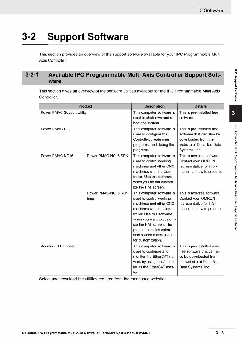
3-2 Support SoftwareThis section provides an overview of the support software available for your IPC Programmable MultiAxis Controller.
3-2-1 Available IPC Programmable Multi Axis Controller Support Soft-ware
This section gives an overview of the software utilities available for the IPC Programmable Multi AxisController.
Product Description DetailsPower PMAC Support Utility This computer software is
used to shutdown and re-boot the system.
This is pre-installed freesoftware.
Power PMAC IDE This computer software isused to configure theController, create userprograms, and debug theprograms.
This is pre-installed freesoftware that can also bedownloaded from thewebsite of Delta Tau DataSystems, Inc.
Power PMAC NC16 Power PMAC-NC16 SDK This computer software isused to control workingmachines and other CNCmachines with the Con-troller. Use this softwarewhen you do not custom-ize the HMI screen.
This is non-free software.Contact your OMRONrepresentative for infor-mation on how to procure.
Power PMAC-NC16 Run-time
This computer software isused to control workingmachines and other CNCmachines with the Con-troller. Use this softwarewhen you want to custom-ize the HMI screen. Theproduct contains exten-sion source codes usedfor customization.
This is non-free software.Contact your OMRONrepresentative for infor-mation on how to procure.
Acontis EC Engineer This computer software isused to configure andmonitor the EtherCAT net-work by using the Control-ler as the EtherCAT mas-ter.
This is pre-installed non-free software that can al-so be downloaded fromthe website of Delta TauData Systems, Inc.
Select and download the utilities required from the mentioned websites.
3 Software
3 - 3NY-series IPC Programmable Multi Axis Controller Hardware User's Manual (W580)
3-2 Support Software
3
3-2-1 Available IPC Program
mable M
ulti Axis Controller Support Softw
are
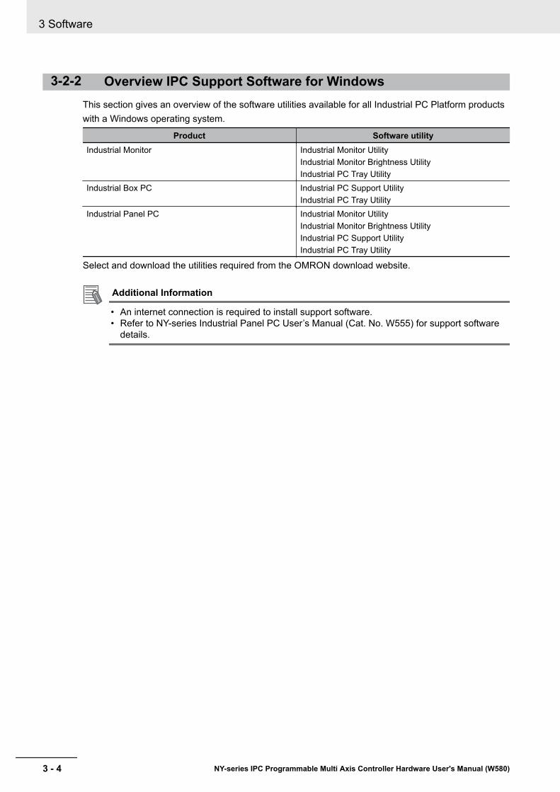
3-2-2 Overview IPC Support Software for WindowsThis section gives an overview of the software utilities available for all Industrial PC Platform productswith a Windows operating system.
Product Software utilityIndustrial Monitor Industrial Monitor Utility
Industrial Monitor Brightness UtilityIndustrial PC Tray Utility
Industrial Box PC Industrial PC Support UtilityIndustrial PC Tray Utility
Industrial Panel PC Industrial Monitor UtilityIndustrial Monitor Brightness UtilityIndustrial PC Support UtilityIndustrial PC Tray Utility
Select and download the utilities required from the OMRON download website.
Additional Information
• An internet connection is required to install support software.• Refer to NY-series Industrial Panel PC User’s Manual (Cat. No. W555) for support software
details.
3 Software
3 - 4 NY-series IPC Programmable Multi Axis Controller Hardware User's Manual (W580)

3-2-3 Power PMAC Support UtilityThis section provides an overview of the Power PMAC Support Utility.
Power PMAC Support UtilityThe Power PMAC Support Utility is a software utility to shutdown and reboot the system when using aIPC Programmable Multi Axis Controller.The Power PMAC Support Utility is located in the system tray.
A
B
C
D
E
F
Item Description Details
A Reboot Complete System Select to reboot both Windows and the IPC Pro-grammable Multi Axis Controller.
B Shutdown Complete System Select to shutdown both Windows and the IPC Pro-grammable Multi Axis Controller.
C Reboot Motion Core Select to reboot only the IPC Programmable MultiAxis Controller. Windows stays operational.
D Update Motion Core Firmware Only use when instructed by authorized supportusers.Select to upgrade the IPC Programmable Multi AxisController.
E Activate EtherCAT License Only use when instructed by authorized supportusers. The license is pre-installed.Select to (re)activate the license for the IPC Pro-grammable Multi Axis Controller.
F Power PMAC Support Utility Icon In the system tray select this icon to display thePower PMAC Support Utility menu.
3 Software
3 - 5NY-series IPC Programmable Multi Axis Controller Hardware User's Manual (W580)
3-2 Support Software
3
3-2-3 Power PM
AC Support U
tility

3-2-4 Industrial PC Support UtilityThis section provides an overview of the Industrial PC Support Utility.
Industrial PC Support Utility OverviewThe Industrial PC Support Utility is a software utility to assist in diagnosing and resolving problems ofthe IPC Programmable Multi Axis Controller.
F E
DCBA
Item Description DetailsA Production Data Tab Select to display Production Data details in the Tab details area C .
Refer to Production Data Tab on page 3 - 7 for details.B System Status Tab Select to display System Status details in the Tab details area C .
Refer to System Status Tab on page 3 - 8 for details.C Tab details Details of the selected Tab page.D Language Selector Select to display and choose the UI language of the Industrial PC Support
Utility.E Close Button Close the Industrial PC Support Utility.F Update Screen Button Use this button to retrieve updated values from the IPC Programmable
Multi Axis Controller.
3 Software
3 - 6 NY-series IPC Programmable Multi Axis Controller Hardware User's Manual (W580)
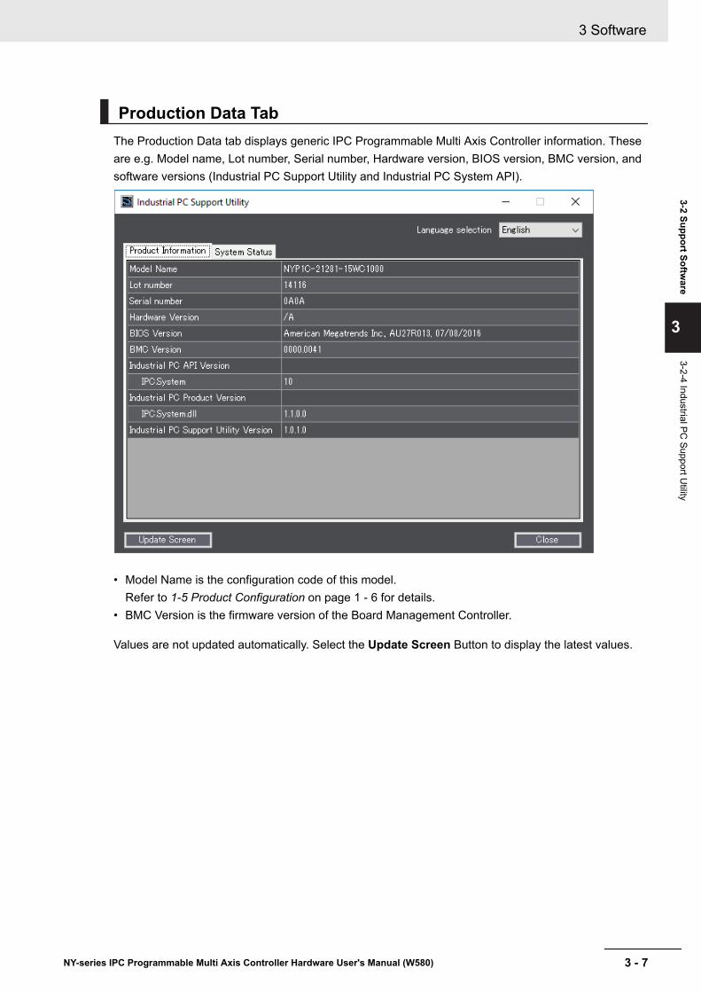
Production Data TabThe Production Data tab displays generic IPC Programmable Multi Axis Controller information. Theseare e.g. Model name, Lot number, Serial number, Hardware version, BIOS version, BMC version, andsoftware versions (Industrial PC Support Utility and Industrial PC System API).
• Model Name is the configuration code of this model.Refer to 1-5 Product Configuration on page 1 - 6 for details.
• BMC Version is the firmware version of the Board Management Controller.
Values are not updated automatically. Select the Update Screen Button to display the latest values.
3 Software
3 - 7NY-series IPC Programmable Multi Axis Controller Hardware User's Manual (W580)
3-2 Support Software
3
3-2-4 Industrial PC Support U
tility

System Status TabThe System Status tab displays actual states and diagnostic information like internal temperature, fanrevolution, battery and power supply status.A status that requires attention is indicated with a red bar.
Item Description
Internal Temperature*1 The average CPU temperature.
Fan Revolution *2 The actual rotation speed for each fan in revolutions per minute (r/min).• First number = rotation speed of fan located closest to Power button.• Second number = rotation speed of fan located closest to battery.
Fan Status *3 The target speed for the fans is dynamically set based on the CPU temperature. Thetarget speed is compared with the actual fan speed.• OK indicates both fans are running on the target speed.• Low revolution speed indicates one or both fans do not reach the target speed.
Clean the fans and replace the Fan Unit if the problem persists.Refer to 7-2-3 Replace the Fan Unit on page 7 - 11 for replacement details.
Battery Status The battery status.• OK indicates the battery is full.• Low indicates the battery voltage is low. Replace the battery.
Refer to 7-2-4 Replace the Battery on page 7 - 13 for replacement details.Power Supply The power supply status is determined by the UPS and reported to the Box PC via the
I/O connector.• NormalPowerSupply indicates the Box PC is powered by the 24V power supply.• UPS Power Supply indicates that there is no power from the 24V power supply
and the Box PC runs on battery power from the UPS.*1. Not for products NY512-A£
Refer to 1-5 Product Configuration on page 1 - 6 for configuration details.*2. The Fan Revolution will always show 0 (r/min) / 0 (r/min) for fanless models
3 Software
3 - 8 NY-series IPC Programmable Multi Axis Controller Hardware User's Manual (W580)

Refer to 1-5 Product Configuration on page 1 - 6 for fan details.*3. The Fan Status will always show OK for fanless models
Values are not updated automatically. Select the Update Screen Button to display the latest values.
InstallationThe Industrial PC Support Utility is pre-installed on the Industrial Box PC and Industrial Panel PC.Download the Industrial PC Support Utility from the OMRON download website if reinstallation is re-quired.
StartupThe Industrial PC Support Utility can be started from:• Windows Start Menu
Select OMRON and then Industrial PC Support Utility.• Industrial PC Tray Utility• Windows desktop shortcut
MessagesThe Industrial PC Support Utility does not display messages in the Industrial PC Tray Utility.A battery warning and a fan warning are not displayed in the Industrial PC Tray Utility.
LoggingThe Industrial Monitor Utility and the Industrial PC Support Utility record the operation history in theWindows event log.Refer to 7-2-9 Windows Event Viewer on page 7 - 30 for the logged messages.
3 Software
3 - 9NY-series IPC Programmable Multi Axis Controller Hardware User's Manual (W580)
3-2 Support Software
3
3-2-4 Industrial PC Support U
tility

3-2-5 Industrial PC Tray UtilityThis section provides an overview of the Industrial PC Tray Utility.
Industrial PC Tray Utility OverviewThe Industrial PC Tray Utility is a software utility that provides information about the current state ofthe Industrial PC, its related devices, and associated software.
When running, the Industrial PC Tray Utility is always present as a status icon A in the system tray
area B of Windows.
A B
Windows 10
FeaturesThe Industrial PC Tray Utility provides the following features:• Display the overall state of all installed OMRON utilities in the icon in the system tray area.• Display a menu that can start all installed utilities and show the state of each installed utility.• Display notification messages in popup windows that inform the user about the state of applications
or hardware. The Industrial PC Tray Utility displays the messages provided by installed OMRONutilities. Refer to the OMRON utilities information for the messages that can be displayed.
Menu
Select the Industrial PC Tray Utility icon F to display the menu.
B
C
E
F
D
A
• The application displays the available utilities.• Select an entry to launch the associated utility, if applicable.
3 Software
3 - 10 NY-series IPC Programmable Multi Axis Controller Hardware User's Manual (W580)
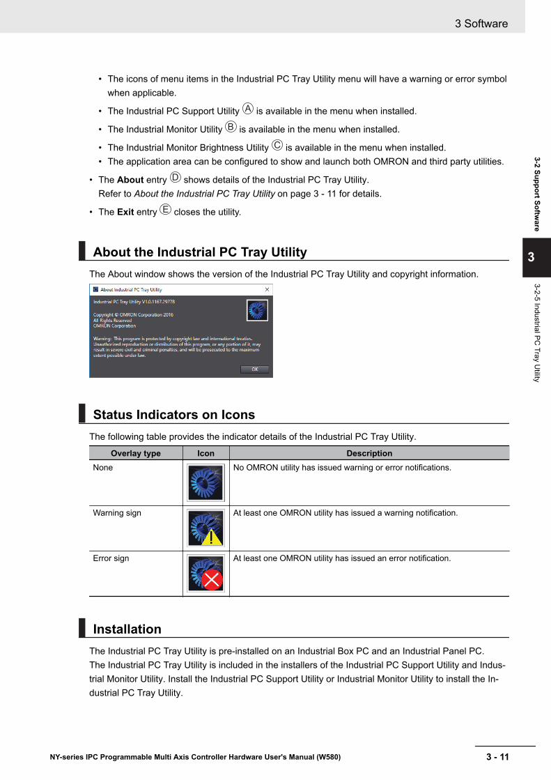
• The icons of menu items in the Industrial PC Tray Utility menu will have a warning or error symbolwhen applicable.
• The Industrial PC Support Utility A is available in the menu when installed.
• The Industrial Monitor Utility B is available in the menu when installed.
• The Industrial Monitor Brightness Utility C is available in the menu when installed.• The application area can be configured to show and launch both OMRON and third party utilities.
• The About entry C D shows details of the Industrial PC Tray Utility.Refer to About the Industrial PC Tray Utility on page 3 - 11 for details.
• The Exit entry E closes the utility.
About the Industrial PC Tray UtilityThe About window shows the version of the Industrial PC Tray Utility and copyright information.
Status Indicators on IconsThe following table provides the indicator details of the Industrial PC Tray Utility.
Overlay type Icon DescriptionNone No OMRON utility has issued warning or error notifications.
Warning sign At least one OMRON utility has issued a warning notification.
Error sign At least one OMRON utility has issued an error notification.
InstallationThe Industrial PC Tray Utility is pre-installed on an Industrial Box PC and an Industrial Panel PC.The Industrial PC Tray Utility is included in the installers of the Industrial PC Support Utility and Indus-trial Monitor Utility. Install the Industrial PC Support Utility or Industrial Monitor Utility to install the In-dustrial PC Tray Utility.
3 Software
3 - 11NY-series IPC Programmable Multi Axis Controller Hardware User's Manual (W580)
3-2 Support Software
3
3-2-5 Industrial PC Tray U
tility
CompatibilityThis software utility can be used on PCs with Windows 7 and Windows 10.
StartupBy default the Industrial PC Tray Utility is configured to start automatically at Windows startup.
To manually start the Industrial PC Tray Utility:
1 Locate the Industrial PC Tray Utility using the Windows Start menu or the Windows searchbox.
2 Use the option Run as administrator to activate the Industrial PC Tray Utility.
Additional Information
The procedure to use Run as administrator is:• For Windows 10 using the Start menu:
Rightclick the Industrial PC Tray Utility, select More and then Run as administrator.• For Windows 10 using Search:
Rightclick the Industrial PC Tray Utility in the search results and select Run asadministrator.
• For Windows 7 using the Start menu or Search:Rightclick the Industrial PC Tray Utility and select Run as administrator.
The Industrial PC Tray Utility started.
3 Software
3 - 12 NY-series IPC Programmable Multi Axis Controller Hardware User's Manual (W580)

3-2-6 Power Attendant Lite UtilityThis section provides an overview of the Power Attendant Lite Utility (PAL).
Power Attendant Lite Utility OverviewThe Power Attendant Lite Utility is a software utility that constantly monitors the status of the UPS thatis connected to the Box PC.When the Power Attendant Lite Utility discovers a power interruption it will send a signal to the Box PCto shut down.Refer to the UPS Power Attendant Lite for Windows User's Manual for details.
FeaturesThe Power Attendant Lite Utility provides the following features:• Signal the Box PC to shut down when a power interruption is detected.• Configure the shutdown conditions when a power interruption is detected.• Display the state of the connected UPS using the icon in the system tray area.
Icon DescriptionNormal operation
Power Attendant Lite service stopped
UPS is supplying power from the internal battery
Communication error
CompatibilityThe Power Attendant Lite Utility can be used on a Box PC with one of the following operating systems:• Windows 10• Windows 7
InstallationThe Power Attendant Lite Utility is not pre-installed on a Box PC.The Power Attendant Lite Utility installer is included in the installers directory (D:\OMRON-NY\Instal-lers). Download the installer from the OMRON download website if required.
To install the Power Attendant Lite Utility:
1 Ensure the revision number of the UPS is correct.
3 Software
3 - 13NY-series IPC Programmable Multi Axis Controller Hardware User's Manual (W580)
3-2 Support Software
3
3-2-6 Power Attendant Lite U
tility
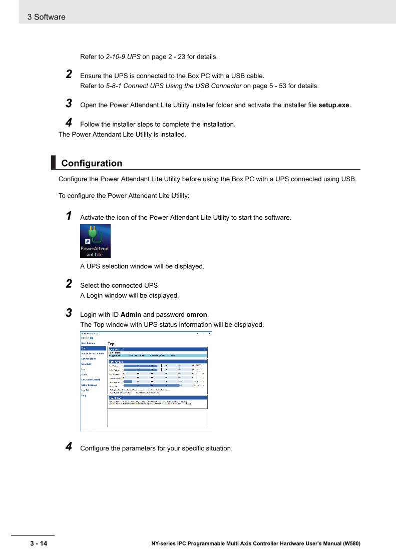
Refer to 2-10-9 UPS on page 2 - 23 for details.
2 Ensure the UPS is connected to the Box PC with a USB cable.Refer to 5-8-1 Connect UPS Using the USB Connector on page 5 - 53 for details.
3 Open the Power Attendant Lite Utility installer folder and activate the installer file setup.exe.
4 Follow the installer steps to complete the installation.The Power Attendant Lite Utility is installed.
ConfigurationConfigure the Power Attendant Lite Utility before using the Box PC with a UPS connected using USB.
To configure the Power Attendant Lite Utility:
1 Activate the icon of the Power Attendant Lite Utility to start the software.
A UPS selection window will be displayed.
2 Select the connected UPS.A Login window will be displayed.
3 Login with ID Admin and password omron.The Top window with UPS status information will be displayed.
4 Configure the parameters for your specific situation.
3 Software
3 - 14 NY-series IPC Programmable Multi Axis Controller Hardware User's Manual (W580)
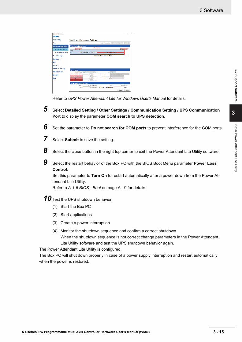
Refer to UPS Power Attendant Lite for Windows User's Manual for details.
5 Select Detailed Setting / Other Settings / Communication Setting / UPS CommunicationPort to display the parameter COM search to UPS detection.
6 Set the parameter to Do not search for COM ports to prevent interference for the COM ports.
7 Select Submit to save the setting.
8 Select the close button in the right top corner to exit the Power Attendant Lite Utility software.
9 Select the restart behavior of the Box PC with the BIOS Boot Menu parameter Power LossControl.Set this parameter to Turn On to restart automatically after a power down from the Power At-tendant Lite Utility.Refer to A-1-5 BIOS - Boot on page A - 9 for details.
10 Test the UPS shutdown behavior.
(1) Start the Box PC
(2) Start applications
(3) Create a power interruption
(4) Monitor the shutdown sequence and confirm a correct shutdownWhen the shutdown sequence is not correct change parameters in the Power AttendantLite Utility software and test the UPS shutdown behavior again.
The Power Attendant Lite Utility is configured.The Box PC will shut down properly in case of a power supply interruption and restart automaticallywhen the power is restored.
3 Software
3 - 15NY-series IPC Programmable Multi Axis Controller Hardware User's Manual (W580)
3-2 Support Software
3
3-2-6 Power Attendant Lite U
tility
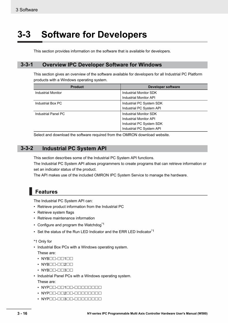
3-3 Software for DevelopersThis section provides information on the software that is available for developers.
3-3-1 Overview IPC Developer Software for WindowsThis section gives an overview of the software available for developers for all Industrial PC Platformproducts with a Windows operating system.
Product Developer softwareIndustrial Monitor Industrial Monitor SDK
Industrial Monitor APIIndustrial Box PC Industrial PC System SDK
Industrial PC System APIIndustrial Panel PC Industrial Monitor SDK
Industrial Monitor APIIndustrial PC System SDKIndustrial PC System API
Select and download the software required from the OMRON download website.
3-3-2 Industrial PC System APIThis section describes some of the Industrial PC System API functions.The Industrial PC System API allows programmers to create programs that can retrieve information orset an indicator status of the product.The API makes use of the included OMRON IPC System Service to manage the hardware.
FeaturesThe Industrial PC System API can:• Retrieve product information from the Industrial PC• Retrieve system flags• Retrieve maintenance information
• Configure and program the Watchdog*1
• Set the status of the Run LED Indicator and the ERR LED Indicator*1
*1 Only for• Industrial Box PCs with a Windows operating system.
These are:• NYB££-££1££• NYB££-££2££• NYB££-££3££
• Industrial Panel PCs with a Windows operating system.These are:• NYP££-££1££-££££££££• NYP££-££2££-££££££££• NYP££-££3££-££££££££
3 Software
3 - 16 NY-series IPC Programmable Multi Axis Controller Hardware User's Manual (W580)
InstallationThe Industrial PC System API is part of the SDK download.The Industrial PC System API is pre-installed on the Industrial Panel PC and the Industrial Box PC.Install the Industrial PC System SDK to use the Industrial PC System API on development PCs.Use the Merge Module to include the Industrial PC System API in the installer for custom applications.To use the Industrial PC System API the API needs to be referenced in your development project.
3 Software
3 - 17NY-series IPC Programmable Multi Axis Controller Hardware User's Manual (W580)
3-3 Software for D
evelopers
3
3-3-2 Industrial PC System
API

3 Software
3 - 18 NY-series IPC Programmable Multi Axis Controller Hardware User's Manual (W580)
4Specifications
This section provides specifications of the IPC Programmable Multi Axis Controller.
4-1 General Specifications ............................................................................... 4 - 24-1-1 Dimensions and Weight ................................................................................ 4 - 24-1-2 General Electrical Specifications .................................................................. 4 - 34-1-3 Power Consumption Specifications .............................................................. 4 - 44-1-4 CPU Specifications ....................................................................................... 4 - 54-1-5 Memory Specifications.................................................................................. 4 - 54-1-6 Storage Device Specifications ...................................................................... 4 - 64-1-7 PCIe Card Specifications.............................................................................. 4 - 74-1-8 Bracket Specifications .................................................................................. 4 - 8
4-2 Connector Specifications ........................................................................... 4 - 94-2-1 Power Connector Specifications................................................................... 4 - 94-2-2 I/O Connector Specifications ...................................................................... 4 - 104-2-3 USB Connector Specifications.................................................................... 4 - 144-2-4 Ethernet Connector Specifications ............................................................. 4 - 154-2-5 DVI Connector Specifications ..................................................................... 4 - 184-2-6 RS-232C Connector Specifications ............................................................ 4 - 19
4-3 Software Specifications ............................................................................ 4 - 204-3-1 Available Windows Operating Systems ...................................................... 4 - 204-3-2 Supported Languages ................................................................................ 4 - 20
4-4 Environmental Specifications................................................................... 4 - 214-4-1 Operation Environment Specifications........................................................ 4 - 214-4-2 Temperature and Humidity Specifications .................................................. 4 - 224-4-3 Recycling Specifications ............................................................................. 4 - 23
4 - 1NY-series IPC Programmable Multi Axis Controller Hardware User's Manual (W580)
4
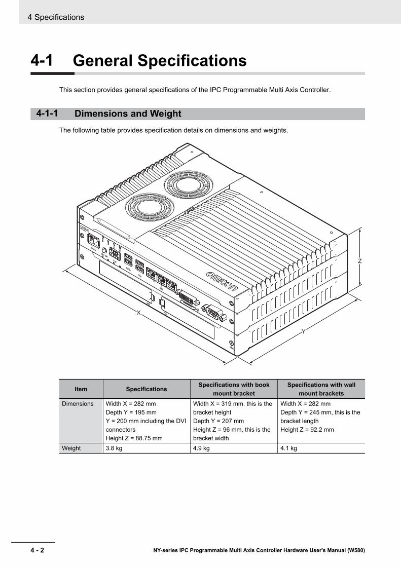
4-1 General SpecificationsThis section provides general specifications of the IPC Programmable Multi Axis Controller.
4-1-1 Dimensions and WeightThe following table provides specification details on dimensions and weights.
Z
Y
X
Item Specifications Specifications with bookmount bracket
Specifications with wallmount brackets
Dimensions Width X = 282 mmDepth Y = 195 mmY = 200 mm including the DVIconnectorsHeight Z = 88.75 mm
Width X = 319 mm, this is thebracket heightDepth Y = 207 mmHeight Z = 96 mm, this is thebracket width
Width X = 282 mmDepth Y = 245 mm, this is thebracket lengthHeight Z = 92.2 mm
Weight 3.8 kg 4.9 kg 4.1 kg
4 Specifications
4 - 2 NY-series IPC Programmable Multi Axis Controller Hardware User's Manual (W580)
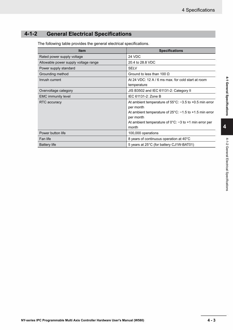
4-1-2 General Electrical SpecificationsThe following table provides the general electrical specifications.
Item SpecificationsRated power supply voltage 24 VDCAllowable power supply voltage range 20.4 to 28.8 VDCPower supply standard SELVGrounding method Ground to less than 100 ΩInrush current At 24 VDC: 12 A / 6 ms max. for cold start at room
temperatureOvervoltage category JIS B3502 and IEC 61131-2: Category IIEMC immunity level IEC 61131-2: Zone BRTC accuracy At ambient temperature of 55°C: −3.5 to +0.5 min error
per monthAt ambient temperature of 25°C: −1.5 to +1.5 min errorper monthAt ambient temperature of 0°C: −3 to +1 min error permonth
Power button life 100,000 operationsFan life 8 years of continuous operation at 40°CBattery life 5 years at 25°C (for battery CJ1W-BAT01)
4 Specifications
4 - 3NY-series IPC Programmable Multi Axis Controller Hardware User's Manual (W580)
4-1 General Specifications
4
4-1-2 General Electrical Specifications

4-1-3 Power Consumption SpecificationsThe following tables provide details on the power consumption of the IPC Programmable Multi AxisController.The total power consumption is the sum of the power consumption of all items that are installed inyour Box PC.
Additional Information
Refer to 1-5 Product Configuration on page 1 - 6 for details.
Power Consumption with an Intel® Core™ i7-4700EQ CPU
Power consumption specifications for IPC Programmable Multi Axis Controllers with an Intel® Core™
i7-4700EQ CPU.
Item Power consumption
Industrial Box PC with Intel® Core™ i7-4700EQ ex-cluding Drives and Expansions
81 W
Drives *1 HDD 320 GB 2 WSSD SLC 32 GBSSD SLC 64 GBSSD iMLC 128 GB
Expansions *2 USB 14 W max. ((2 x 500 mA at 5 V) + (2 x 900 mA at 5 V))PCIe 15 W max.
*1. Refer to 1-5 Product Configuration on page 1 - 6 for product configuration details.*2. Refer to the documentation of your expansions for their power consumption details.
The total power consumption is the sum of the power consumption of all items that are installed inyour IPC Programmable Multi Axis Controller.
The required supply specifications for a Box PC with an Intel® Core™ i7-4700EQ CPU.
Item Minimum power requirementsPower supplyRefer to 2-10-8 Power Supply on page 2 - 22 for pow-er supply products.
240 W
UPSRefer to 2-10-9 UPS on page 2 - 23 for UPS products.
120 W
4 Specifications
4 - 4 NY-series IPC Programmable Multi Axis Controller Hardware User's Manual (W580)
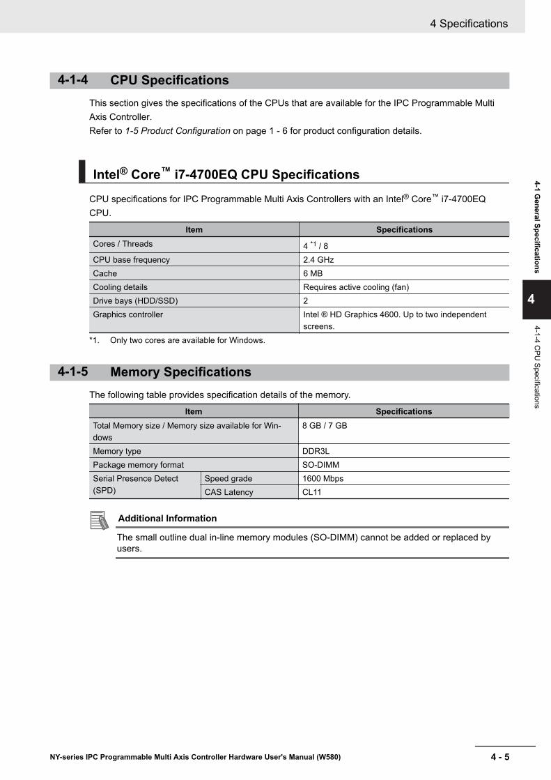
4-1-4 CPU SpecificationsThis section gives the specifications of the CPUs that are available for the IPC Programmable MultiAxis Controller.Refer to 1-5 Product Configuration on page 1 - 6 for product configuration details.
Intel® Core™ i7-4700EQ CPU Specifications
CPU specifications for IPC Programmable Multi Axis Controllers with an Intel® Core™ i7-4700EQCPU.
Item SpecificationsCores / Threads 4 *1 / 8CPU base frequency 2.4 GHzCache 6 MBCooling details Requires active cooling (fan)Drive bays (HDD/SSD) 2Graphics controller Intel ® HD Graphics 4600. Up to two independent
screens.*1. Only two cores are available for Windows.
4-1-5 Memory SpecificationsThe following table provides specification details of the memory.
Item SpecificationsTotal Memory size / Memory size available for Win-dows
8 GB / 7 GB
Memory type DDR3LPackage memory format SO-DIMMSerial Presence Detect(SPD)
Speed grade 1600 MbpsCAS Latency CL11
Additional Information
The small outline dual in-line memory modules (SO-DIMM) cannot be added or replaced byusers.
4 Specifications
4 - 5NY-series IPC Programmable Multi Axis Controller Hardware User's Manual (W580)
4-1 General Specifications
4
4-1-4 CPU
Specifications

4-1-6 Storage Device SpecificationsThis section provides the specifications of the storage devices.
Solid State Drive SpecificationsSpecifications for the Solid State Drive (SSD) are provided in the table below.
ItemModel Specifications
32 GB *1 64 GB *1 128 GB *1
Model NY000-AS00 NY000-AS01 NY000-AS02Type SLC SLC iMLCS.M.A.R.T. support YesInterface Serial ATA 3.1Sustained read speed Up to 160 MB/s Up to 430 MB/sSustained write speed Up to 150 MB/s Up to 190 MB/sOperating temperature 0 to 70°C *2
Operating humidity 10% to 95% (with no condensation)Storage temperature -40 to 100°CStorage humidity 10% to 95% (with no condensation)Life 1500 TB/11 years at a
daily workload of 350 GB3000 TB/23 years at adaily workload of 350 GB
114 TB/3 years at a dailyworkload of 100 GB
*1. Refer to 1-5 Product Configuration on page 1 - 6 for product configuration details.*2. Refer to 4-4-1 Operation Environment Specifications on page 4 - 21 for the temperature specifications of
the complete Box PC
4 Specifications
4 - 6 NY-series IPC Programmable Multi Axis Controller Hardware User's Manual (W580)

4-1-7 PCIe Card SpecificationsThe PCI Express (PCIe) Card slot of the IPC Programmable Multi Axis Controller accepts variouscards for specific hardware needs.
Ensure that, according to the PCIe hardware specifications, the indent A is present in the PCIe Card.
A
The following tables provide PCIe Card details per CPU type.
PCIe Card Slot Specifications with an Intel® Core™ i7-4700EQ CPUThe table below provides PCIe Card slot details for IPC Programmable Multi Axis Controllers with an
Intel® Core™ i7-4700EQ CPU.
Item SpecificationsConfiguration X4 (4 lanes) up to Gen 3Card height Standard height cards, 4.20 inches (106.7 mm)*1
Card length Half-length cards, 6.6 inches (167.65 mm)Power consumption Refer to Power Consumption with an Intel® Core™ i7-4700EQ CPU on page 4 - 4
for the maximum power consumption*1. Low profile cards, 2.536 inches (64.4 mm) are not supported.
4 Specifications
4 - 7NY-series IPC Programmable Multi Axis Controller Hardware User's Manual (W580)
4-1 General Specifications
4
4-1-7 PCIe C
ard Specifications

4-1-8 Bracket SpecificationsThe metal mounting brackets mount your Box PC and they are the connection for the functionalground.Use metal screws with a diameter of 4 mm or 5 mm to mount the brackets.Mounting screw locations for book mount and wall mount orientation:
10.5
10.5
60
303
11.5
11.5
245
218
Additional Information
• Refer to 5-3-8 Book Mount Procedure on page 5 - 25 for book mount details.• Refer to 5-3-9 Wall Mount Procedure on page 5 - 26 for wall mount details.
4 Specifications
4 - 8 NY-series IPC Programmable Multi Axis Controller Hardware User's Manual (W580)
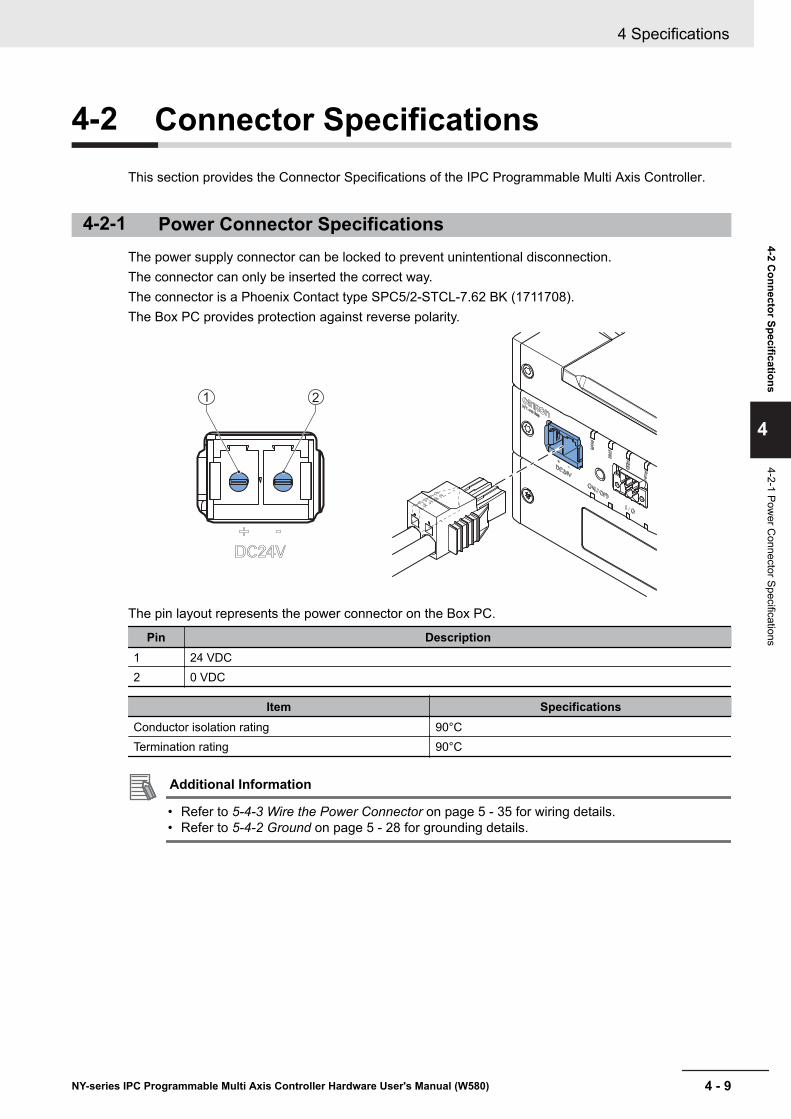
4-2 Connector SpecificationsThis section provides the Connector Specifications of the IPC Programmable Multi Axis Controller.
4-2-1 Power Connector SpecificationsThe power supply connector can be locked to prevent unintentional disconnection.The connector can only be inserted the correct way.The connector is a Phoenix Contact type SPC5/2-STCL-7.62 BK (1711708).The Box PC provides protection against reverse polarity.
21
The pin layout represents the power connector on the Box PC.
Pin Description1 24 VDC2 0 VDC
Item SpecificationsConductor isolation rating 90°CTermination rating 90°C
Additional Information
• Refer to 5-4-3 Wire the Power Connector on page 5 - 35 for wiring details.• Refer to 5-4-2 Ground on page 5 - 28 for grounding details.
4 Specifications
4 - 9NY-series IPC Programmable Multi Axis Controller Hardware User's Manual (W580)
4-2 Connector Specifications
4
4-2-1 Power C
onnector Specifications
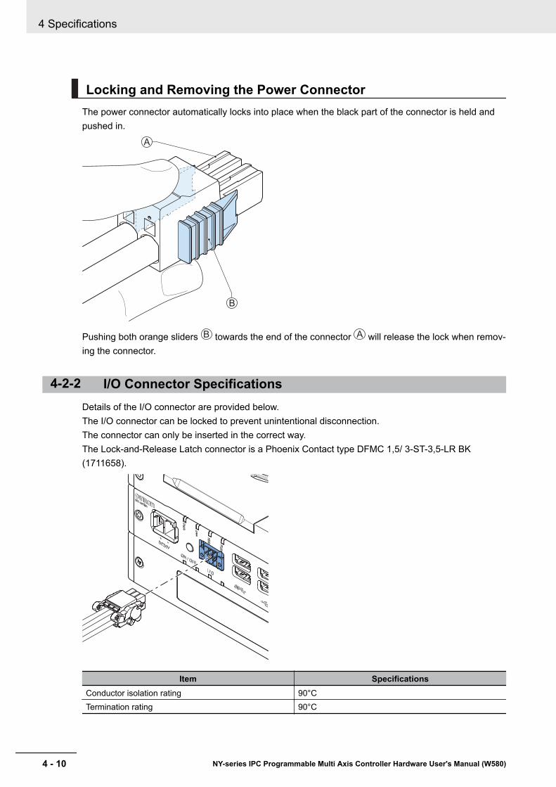
Locking and Removing the Power ConnectorThe power connector automatically locks into place when the black part of the connector is held andpushed in.
B
A
Pushing both orange sliders B towards the end of the connector A will release the lock when remov-ing the connector.
4-2-2 I/O Connector SpecificationsDetails of the I/O connector are provided below.The I/O connector can be locked to prevent unintentional disconnection.The connector can only be inserted in the correct way.The Lock-and-Release Latch connector is a Phoenix Contact type DFMC 1,5/ 3-ST-3,5-LR BK(1711658).
Item SpecificationsConductor isolation rating 90°CTermination rating 90°C
4 Specifications
4 - 10 NY-series IPC Programmable Multi Axis Controller Hardware User's Manual (W580)
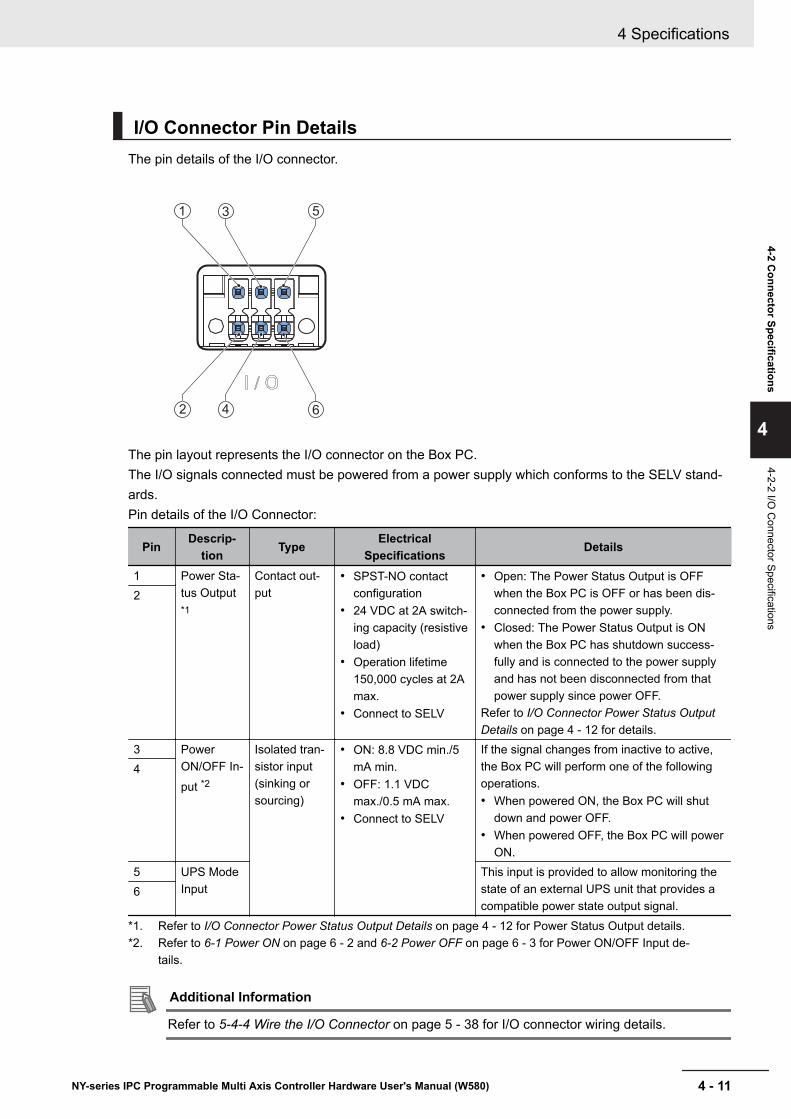
I/O Connector Pin DetailsThe pin details of the I/O connector.
2 4
5
6
1 3
The pin layout represents the I/O connector on the Box PC.The I/O signals connected must be powered from a power supply which conforms to the SELV stand-ards.Pin details of the I/O Connector:
Pin Descrip-tion Type Electrical
Specifications Details
1 Power Sta-tus Output*1
Contact out-put
• SPST-NO contactconfiguration
• 24 VDC at 2A switch-ing capacity (resistiveload)
• Operation lifetime150,000 cycles at 2Amax.
• Connect to SELV
• Open: The Power Status Output is OFFwhen the Box PC is OFF or has been dis-connected from the power supply.
• Closed: The Power Status Output is ONwhen the Box PC has shutdown success-fully and is connected to the power supplyand has not been disconnected from thatpower supply since power OFF.
Refer to I/O Connector Power Status OutputDetails on page 4 - 12 for details.
2
3 PowerON/OFF In-put *2
Isolated tran-sistor input(sinking orsourcing)
• ON: 8.8 VDC min./5mA min.
• OFF: 1.1 VDCmax./0.5 mA max.
• Connect to SELV
If the signal changes from inactive to active,the Box PC will perform one of the followingoperations.• When powered ON, the Box PC will shut
down and power OFF.• When powered OFF, the Box PC will power
ON.
4
5 UPS ModeInput
This input is provided to allow monitoring thestate of an external UPS unit that provides acompatible power state output signal.
6
*1. Refer to I/O Connector Power Status Output Details on page 4 - 12 for Power Status Output details.*2. Refer to 6-1 Power ON on page 6 - 2 and 6-2 Power OFF on page 6 - 3 for Power ON/OFF Input de-
tails.
Additional Information
Refer to 5-4-4 Wire the I/O Connector on page 5 - 38 for I/O connector wiring details.
4 Specifications
4 - 11NY-series IPC Programmable Multi Axis Controller Hardware User's Manual (W580)
4-2 Connector Specifications
4
4-2-2 I/O C
onnector Specifications
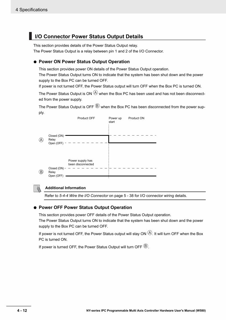
I/O Connector Power Status Output DetailsThis section provides details of the Power Status Output relay.The Power Status Output is a relay between pin 1 and 2 of the I/O Connector.
Power ON Power Status Output OperationThis section provides power ON details of the Power Status Output operation.The Power Status Output turns ON to indicate that the system has been shut down and the powersupply to the Box PC can be turned OFF.If power is not turned OFF, the Power Status output will turn OFF when the Box PC is turned ON.
The Power Status Output is ON A when the Box PC has been used and has not been disconnect-ed from the power supply.
The Power Status Output is OFF B when the Box PC has been disconnected from the power sup-ply.
Power up
start
Power supply has
been disconnected
Open (OFF)
Closed (ON)
Relay
Open (OFF)
Closed (ON)
Relay
A
B
Product ONProduct OFF
Additional Information
Refer to 5-4-4 Wire the I/O Connector on page 5 - 38 for I/O connector wiring details.
Power OFF Power Status Output OperationThis section provides power OFF details of the Power Status Output operation.The Power Status Output turns ON to indicate that the system has been shut down and the powersupply to the Box PC can be turned OFF.
If power is not turned OFF, the Power Status output will stay ON A . It will turn OFF when the BoxPC is turned ON.
If power is turned OFF, the Power Status Output will turn OFF B .
4 Specifications
4 - 12 NY-series IPC Programmable Multi Axis Controller Hardware User's Manual (W580)

Shutdown
start
Shutdown
finished
Power supply
removed
Open (OFF)
Closed (ON)
Relay
Open (OFF)
Closed (ON)
Relay
A
B
Product ON Product OFF
Additional Information
Refer to 5-4-4 Wire the I/O Connector on page 5 - 38 for I/O connector wiring details.
Lock and Remove the I/O ConnectorThe I/O connector locks into place when the black part of the connector is held and pushed in.
B
A
Tilting both levers B will release the I/O connector A from the Box PC.
4 Specifications
4 - 13NY-series IPC Programmable Multi Axis Controller Hardware User's Manual (W580)
4-2 Connector Specifications
4
4-2-2 I/O C
onnector Specifications
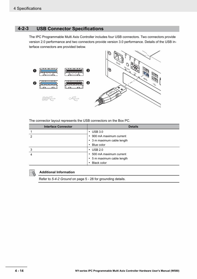
4-2-3 USB Connector SpecificationsThe IPC Programmable Multi Axis Controller includes four USB connectors. Two connectors provideversion 2.0 performance and two connectors provide version 3.0 performance. Details of the USB in-terface connectors are provided below.
1
2
3
4
The connector layout represents the USB connectors on the Box PC.
Interface Connector Details1 • USB 3.0
• 900 mA maximum current• 3 m maximum cable length• Blue color
2
3 • USB 2.0• 500 mA maximum current• 5 m maximum cable length• Black color
4
Additional Information
Refer to 5-4-2 Ground on page 5 - 28 for grounding details.
4 Specifications
4 - 14 NY-series IPC Programmable Multi Axis Controller Hardware User's Manual (W580)

4-2-4 Ethernet Connector SpecificationsDetails of the RJ45 Ethernet connectors are provided below.There are three Ethernet ports, each with a specific function.The Ethernet connectors are designated in the following manner.• Connector number 1: EtherCAT.
This port is available for the Programmable Multi Axis Controller.• Connector number 2: Ethernet.
This port is available for the Programmable Multi Axis Controller and supports Modbus-TCP.• Connector number 3: Ethernet.
This port is available for Windows.
Additional Information
Refer to 2-10-11 Recommended EtherCAT Cables on page 2 - 24 for cable details.
The Ethernet connector locks automatically to prevent unintentional disconnection.
13 2
The view represents the Ethernet connector on the Box PC.
4 Specifications
4 - 15NY-series IPC Programmable Multi Axis Controller Hardware User's Manual (W580)
4-2 Connector Specifications
4
4-2-4 Ethernet Connector Specifications
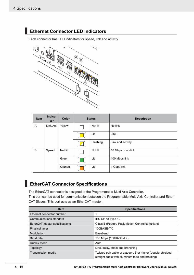
Ethernet Connector LED IndicatorsEach connector has LED indicators for speed, link and activity.
B
A
Item Indica-tor Color Status Description
A Link/Act Yellow Not lit No link
Lit Link
Flashing Link and activity
B Speed Not lit Not lit 10 Mbps or no link
Green Lit 100 Mbps link
Orange Lit 1 Gbps link
EtherCAT Connector SpecificationsThe EtherCAT connector is assigned to the Programmable Multi Axis Controller.This port can be used for communication between the Programmable Multi Axis Controller and Ether-CAT Slaves. This port acts as an EtherCAT master.
Item SpecificationsEthernet connector number 1Communications standard IEC 61158 Type 12EtherCAT master specifications Class B (Feature Pack Motion Control compliant)Physical layer 100BASE-TXModulation BasebandBaud rate 100 Mbps (100BASE-TX)Duplex mode AutoTopology Line, daisy, chain and branchingTransmission media Twisted pair cable of category 5 or higher (double-shielded
straight cable with aluminum tape and braiding)
4 Specifications
4 - 16 NY-series IPC Programmable Multi Axis Controller Hardware User's Manual (W580)
Item SpecificationsMaximum transmission distance between nodes 100 mMaximum number of slaves 192Range of node addresses that can be set 1 to 512Maximum process data size Input: 5,736 bytes, Output 5,736 bytes, the maximum number
of process data frames is 4Maximum process data size per slave Input 1,434 bytes, Output 1,434 bytesCommunications cycle 500 µs to 8 ms in 250 µs-incrementsSync jitter 1 µs max.
Modbus-TCP Connector SpecificationsThe Modbus-TCP connector is assigned to the Programmable Multi Axis Controller and acts as regu-lar Ethernet port.
Item SpecificationsEthernet connector number 2Physical layer 10BASE-T, 100BASE-TX or 1000BASE-TFrame length 1,514 bytes max.Media access method CSMA/CDModulation BasebandTopology StarTransmission media STP (shielded, twisted pair) cable of Ethernet category
5,5e or higherMaximum transmission distance between Ethernetswitch and node
100 m
Maximum number of cascade connections There are no restrictions if an Ethernet switch is used
Ethernet Connector SpecificationsThis Ethernet connector is available in Windows and acts as regular Ethernet port.
Item SpecificationsEthernet connector number 3Physical layer 10BASE-T, 100BASE-TX or 1000BASE-TFrame length 1,514 bytes max.Media access method CSMA/CDModulation BasebandTopology StarTransmission media STP (shielded, twisted pair) cable of Ethernet category
5,5e or higherMaximum transmission distance between Ethernetswitch and node
100 m
Maximum number of cascade connections There are no restrictions if an Ethernet switch is used
4 Specifications
4 - 17NY-series IPC Programmable Multi Axis Controller Hardware User's Manual (W580)
4-2 Connector Specifications
4
4-2-4 Ethernet Connector Specifications

4-2-5 DVI Connector SpecificationsDVI is the standard video interface for the Box PC.The video interface depends on the model of the Box PC as specified below:
Additional Information
• Refer to 4-1-4 CPU Specifications on page 4 - 5 for graphics controller details.• Refer to 5-4-2 Ground on page 5 - 28 for grounding details.• Refer to A-3 DVI-I Connector Pin Details on page A - 14 for pin details.
The following tables provide DVI details per CPU type.
DVI-I Connector Specifications with an Intel® Core™ i7-4700EQCPU
DVI-I connector specifications for IPC Programmable Multi Axis Controllers with an Intel® Core™
i7-4700EQ CPU.
Item SpecificationsVideo interface Digital or AnalogResolution Up to 1920 x 1200 pixels at 60 HzType Dual linkMaximum DVI cable length Dependent upon connected monitor type and resolution
4 Specifications
4 - 18 NY-series IPC Programmable Multi Axis Controller Hardware User's Manual (W580)
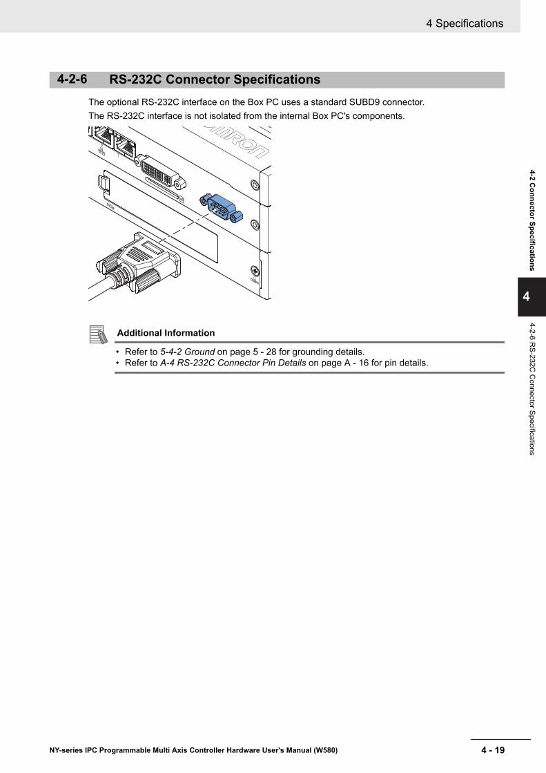
4-2-6 RS-232C Connector SpecificationsThe optional RS-232C interface on the Box PC uses a standard SUBD9 connector.The RS-232C interface is not isolated from the internal Box PC's components.
Additional Information
• Refer to 5-4-2 Ground on page 5 - 28 for grounding details.• Refer to A-4 RS-232C Connector Pin Details on page A - 16 for pin details.
4 Specifications
4 - 19NY-series IPC Programmable Multi Axis Controller Hardware User's Manual (W580)
4-2 Connector Specifications
4
4-2-6 RS-232C
Connector Specifications
4-3 Software SpecificationsThis section provides the Software Specifications of the IPC Programmable Multi Axis Controller.
4-3-1 Available Windows Operating SystemsThe available Windows Operating System is Windows Embedded Standard 7 SP1 - 64 bits.
4-3-2 Supported LanguagesLanguages default supported by the operating system are:
Language Windows 7 Windows 10EN
CN Simplified (zh-cn)
CN Traditional (zh-tw)
DE
ES
FR
IT
JA
KO
Additional Information
Refer to the Microsoft support information for details on available language packs.
4 Specifications
4 - 20 NY-series IPC Programmable Multi Axis Controller Hardware User's Manual (W580)
4-4 Environmental SpecificationsThis section provides environmental specifications of the IPC Programmable Multi Axis Controller.
4-4-1 Operation Environment SpecificationsThe following table provides the general environmental specifications for the Industrial Box PC.
Item SpecificationsAmbient operating temperature 0 to 55°C *1
Ambient storage temperature -20 to 70°C *1
Ambient operating humidity 10% to 90% with no condensationAmbient storage humidity 10% to 90% with no condensationOperating atmosphere No corrosive gasesAltitude 2,000 m max.Noise resistance (during operation) Conforms to IEC61000-4-4, 2kV (power lines)Vibration resistance (during opera-tion)
Conforms to IEC 60068-2-6.For a Box PC with an SSD: 5 to 8.4 Hz with 3.5 mm single amplitude and8.4 to 150 Hz with 9.8 m/s² for 10 times each in X, Y and Z directions.For a Box PC with a HDD the vibration resistance depends on the mount-ing orientation*2.
Shock resistance (during operation) Conforms to IEC 60068-2-27.147 m/s², 3 times in each X, Y and Z directions
Pollution degree JIS B3502 and IEC 61131-2: 2 or lessRTC accuracy At ambient temperature of 55°C: −3.5 to +0.5 min error per month
At ambient temperature of 25°C: −1.5 to +1.5 min error per monthAt ambient temperature of 0°C: −3 to +1 min error per month
*1. Refer to 4-4-2 Temperature and Humidity Specifications on page 4 - 22 for ambient operating temperaturedetails per CPU type.
*2. Vibration resistance depends on the Box PC's mounting orientation and storage device type:
Mounting Orientation SSD HDDBook 9.8 m/s² 2.5 m/s²Wall 4.9 m/s²
4 Specifications
4 - 21NY-series IPC Programmable Multi Axis Controller Hardware User's Manual (W580)
4-4 Environmental Specifications
4
4-4-1 Operation Environm
ent Specifications
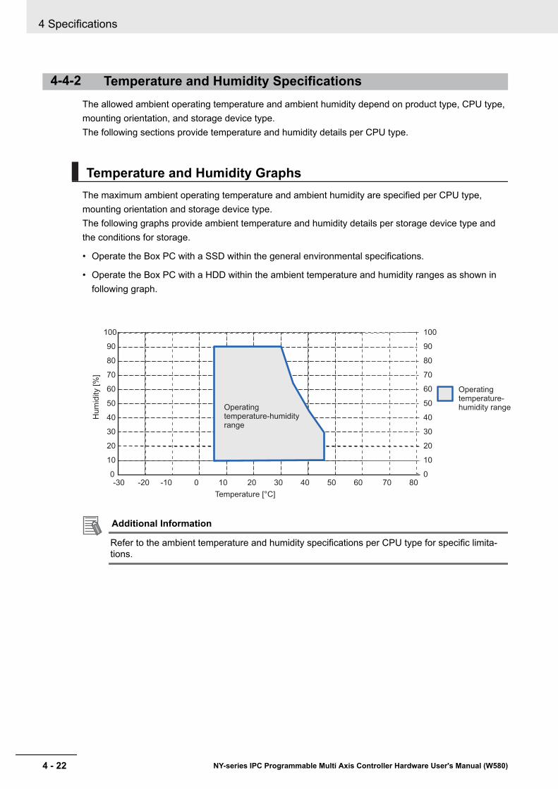
4-4-2 Temperature and Humidity SpecificationsThe allowed ambient operating temperature and ambient humidity depend on product type, CPU type,mounting orientation, and storage device type.The following sections provide temperature and humidity details per CPU type.
Temperature and Humidity GraphsThe maximum ambient operating temperature and ambient humidity are specified per CPU type,mounting orientation and storage device type.The following graphs provide ambient temperature and humidity details per storage device type andthe conditions for storage.
• Operate the Box PC with a SSD within the general environmental specifications.
• Operate the Box PC with a HDD within the ambient temperature and humidity ranges as shown infollowing graph.
Hu
mid
ity [
%]
Operatingtemperature-humidity range
Temperature [°C]
0
10
20
30
40
50
60
70
80
90
100
-30 -20 -10 0 10 20 30 40 50 60 70 800
10
20
30
40
50
60
70
80
90
100
Operatingtemperature-humidity range
Additional Information
Refer to the ambient temperature and humidity specifications per CPU type for specific limita-tions.
4 Specifications
4 - 22 NY-series IPC Programmable Multi Axis Controller Hardware User's Manual (W580)

• Store the Box PC with a SSD within the general environmental specifications.
• Store the Box PC with a HDD within the ambient temperature and humidity ranges as shown in fol-lowing graph.
Hu
mid
ity [
%]
Storage temperature-humidity range
Temperature [°C]
0
10
20
30
40
50
60
70
80
90
100
-30 -20 -10 0 10 20 30 40 50 60 70 800
10
20
30
40
50
60
70
80
90
100
Storage temperature-humidity range
Temperature Specifications with an Intel® Core™ i7-4700EQ CPU
Ambient operating temperature specifications for a Box PC with an Intel® Core™ i7-4700EQ CPU.
Mounting Ori-entation
Storage device type *1
1 x SSD 2 x SSD 1 x HDD 2 x HDD 1 x SSD 1 xHDD
Book 0 to 55°C 5 to 45°C 5 to 35°C 5 to 45°CWall 0 to 55°C 5 to 45°C 5 to 35°C 5 to 45°C
*1. Refer to 1-5 Product Configuration on page 1 - 6 for model details.
Additional Information
Refer to Temperature and Humidity Graphs on page 4 - 22 for graph details.
4-4-3 Recycling SpecificationsThe following table provides recycling information for the IPC Programmable Multi Axis Controller.
Part Recycle specificationsBattery Chemical wastePCIe Card and other electrical components Electrical waste
Precautions for Safe Use
Dispose of the product and batteries according to local ordinances as they apply.
4 Specifications
4 - 23NY-series IPC Programmable Multi Axis Controller Hardware User's Manual (W580)
4-4 Environmental Specifications
4
4-4-3 Recycling Specifications

4 Specifications
4 - 24 NY-series IPC Programmable Multi Axis Controller Hardware User's Manual (W580)

5Installation
This section provides all installation details for the IPC Programmable Multi Axis Con-troller.
5-1 Unpack .......................................................................................................... 5 - 35-1-1 Unpack Procedure ........................................................................................ 5 - 35-1-2 Items Supplied .............................................................................................. 5 - 3
5-2 Install Options .............................................................................................. 5 - 65-2-1 Install a Drive ................................................................................................ 5 - 65-2-2 Install the PCIe Card................................................................................... 5 - 10
5-3 Mount........................................................................................................... 5 - 155-3-1 Installation Method in Control Panels ......................................................... 5 - 155-3-2 Product Orientation..................................................................................... 5 - 165-3-3 Temperature................................................................................................ 5 - 165-3-4 Humidity...................................................................................................... 5 - 195-3-5 Vibration and Shock.................................................................................... 5 - 195-3-6 Atmosphere ................................................................................................ 5 - 205-3-7 Electrical Environment ................................................................................ 5 - 205-3-8 Book Mount Procedure ............................................................................... 5 - 255-3-9 Wall Mount Procedure ................................................................................ 5 - 26
5-4 Wire.............................................................................................................. 5 - 275-4-1 Wiring Warnings and Cautions ................................................................... 5 - 275-4-2 Ground........................................................................................................ 5 - 285-4-3 Wire the Power Connector.......................................................................... 5 - 355-4-4 Wire the I/O Connector ............................................................................... 5 - 38
5-5 Connect ....................................................................................................... 5 - 415-5-1 Connector Identification .............................................................................. 5 - 425-5-2 Connection Procedure ................................................................................ 5 - 435-5-3 Ethernet Connection Procedure ................................................................. 5 - 44
5-6 Initial Power ON.......................................................................................... 5 - 455-6-1 Initial Power ON Procedure ........................................................................ 5 - 455-6-2 Windows Startup First Time........................................................................ 5 - 47
5-7 Install Software........................................................................................... 5 - 495-7-1 Internet Browser ......................................................................................... 5 - 495-7-2 Firewall ....................................................................................................... 5 - 505-7-3 Anti-virus Software...................................................................................... 5 - 505-7-4 Drivers and Custom Software..................................................................... 5 - 515-7-5 Customize Windows ................................................................................... 5 - 51
5-8 Connect UPS .............................................................................................. 5 - 52
5 - 1NY-series IPC Programmable Multi Axis Controller Hardware User's Manual (W580)
5
5-8-1 Connect UPS Using the USB Connector.................................................... 5 - 535-8-2 Connect UPS Using the I/O Connector ...................................................... 5 - 56
5-9 Create a Windows System Repair Disk and a Windows Backup........... 5 - 595-9-1 Industrial PC with Programmable Multi Axis Controller Backup ................. 5 - 595-9-2 Create a Windows System Repair Disk...................................................... 5 - 59
5 Installation
5 - 2 NY-series IPC Programmable Multi Axis Controller Hardware User's Manual (W580)
5-1 UnpackThis section provides details on how to unpack the IPC Programmable Multi Axis Controller.
5-1-1 Unpack Procedure
1 Check the package for damage.If there is any visible damage:• Take photos of the package and save them.• Inform your supplier immediately.
2 Open the package.Ensure not to damage the contents.
3 Ensure that all items are present.
Additional Information
Refer to 5-1-2 Items Supplied on page 5 - 3 for the items supplied.
5-1-2 Items SuppliedThe Industrial Box PC is supplied with several items.
Additional Information
• Refer to Items Supplied with the Industrial Box PC on page 5 - 4 for more details.• Refer to Items Supplied with the Brackets on page 5 - 5 for more details.
5 Installation
5 - 3NY-series IPC Programmable Multi Axis Controller Hardware User's Manual (W580)
5-1 Unpack
5
5-1-1 Unpack Procedure

Items Supplied with the Industrial Box PCThis section describes the items supplied with your Industrial Box PC.• Industrial Box PC• Documentation:
• Safety Precautions sheets (English and Japanese)• EU Compliance sheet• Standards and Certifications sheet
• Bag with:• Power connector• I/O connector• Drive bracket for drive installation• 4 Mounting screws for drive installation• PCIe Card support for PCIe Card installation
Industri
al Box P
C
5 Installation
5 - 4 NY-series IPC Programmable Multi Axis Controller Hardware User's Manual (W580)

Items Supplied with the BracketsThis section describes the items supplied with the brackets for your Industrial Box PC.
Additional Information
• Refer to 2-10-1 Mounting Brackets on page 2 - 19 for bracket details.• Refer to 5-3-8 Book Mount Procedure on page 5 - 25 for book mount installation.• Refer to 5-3-9 Wall Mount Procedure on page 5 - 26 for wall mount installation.
Book MountCheck if the content is complete.Supplied items:• 1 Book mount bracket• 6 Mounting screws• 1 Nut for the functional ground terminal connection• 2 Washers for the functional ground terminal connection
Wall MountCheck if the content is complete.Supplied items:• 2 Wall mount brackets• 6 Mounting screws• 1 Nut for the functional ground terminal connection• 2 Washers for the functional ground terminal connection
5 Installation
5 - 5NY-series IPC Programmable Multi Axis Controller Hardware User's Manual (W580)
5-1 Unpack
5
5-1-2 Items Supplied
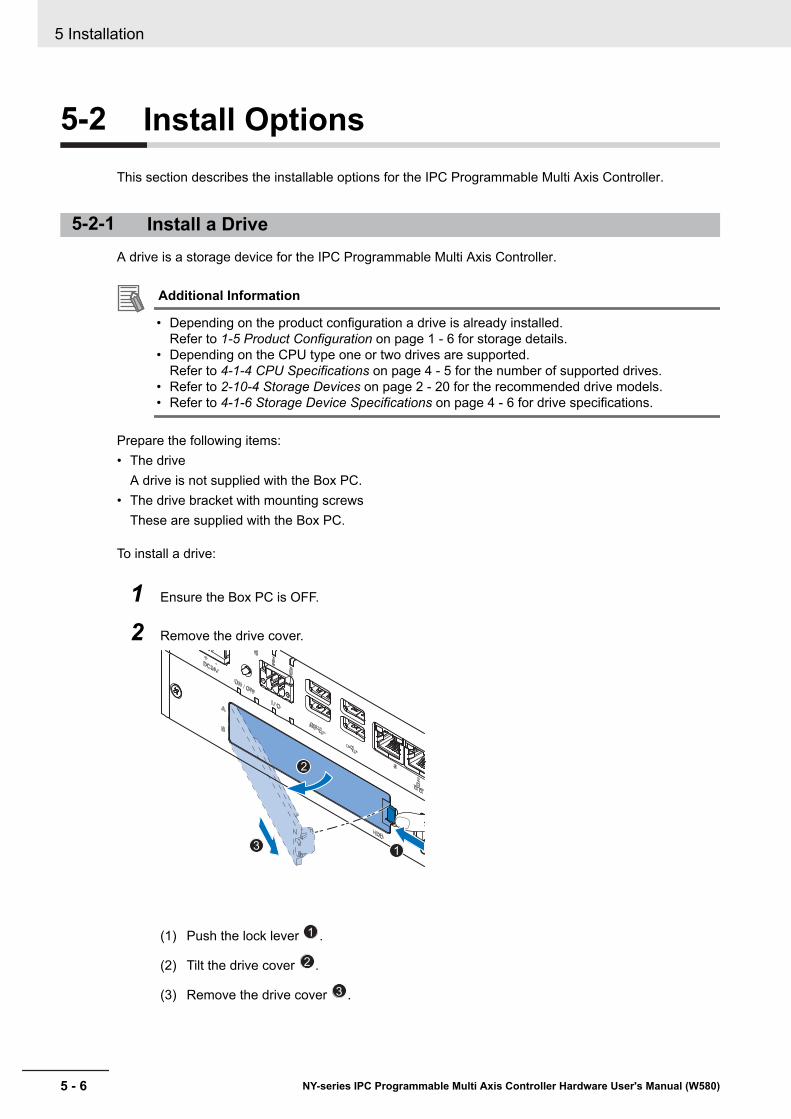
5-2 Install OptionsThis section describes the installable options for the IPC Programmable Multi Axis Controller.
5-2-1 Install a DriveA drive is a storage device for the IPC Programmable Multi Axis Controller.
Additional Information
• Depending on the product configuration a drive is already installed.Refer to 1-5 Product Configuration on page 1 - 6 for storage details.
• Depending on the CPU type one or two drives are supported.Refer to 4-1-4 CPU Specifications on page 4 - 5 for the number of supported drives.
• Refer to 2-10-4 Storage Devices on page 2 - 20 for the recommended drive models.• Refer to 4-1-6 Storage Device Specifications on page 4 - 6 for drive specifications.
Prepare the following items:• The drive
A drive is not supplied with the Box PC.• The drive bracket with mounting screws
These are supplied with the Box PC.
To install a drive:
1 Ensure the Box PC is OFF.
2 Remove the drive cover.
13
2
(1) Push the lock lever 1 .
(2) Tilt the drive cover 2 .
(3) Remove the drive cover 3 .
5 Installation
5 - 6 NY-series IPC Programmable Multi Axis Controller Hardware User's Manual (W580)
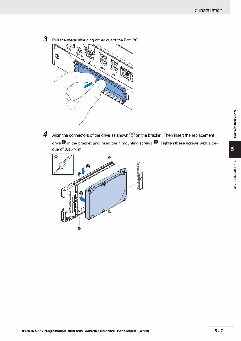
3 Pull the metal shielding cover out of the Box PC.
4 Align the connectors of the drive as shown A on the bracket. Then insert the replacement
drive 1 in the bracket and insert the 4 mounting screws 2 . Tighten these screws with a tor-que of 0.35 N·m.
A0
15
5 Installation
5 - 7NY-series IPC Programmable Multi Axis Controller Hardware User's Manual (W580)
5-2 Install Options
5
5-2-1 Install a Drive
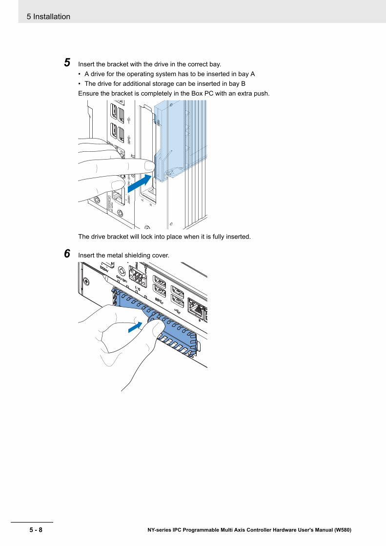
5 Insert the bracket with the drive in the correct bay.• A drive for the operating system has to be inserted in bay A• The drive for additional storage can be inserted in bay BEnsure the bracket is completely in the Box PC with an extra push.
The drive bracket will lock into place when it is fully inserted.
6 Insert the metal shielding cover.
5 Installation
5 - 8 NY-series IPC Programmable Multi Axis Controller Hardware User's Manual (W580)
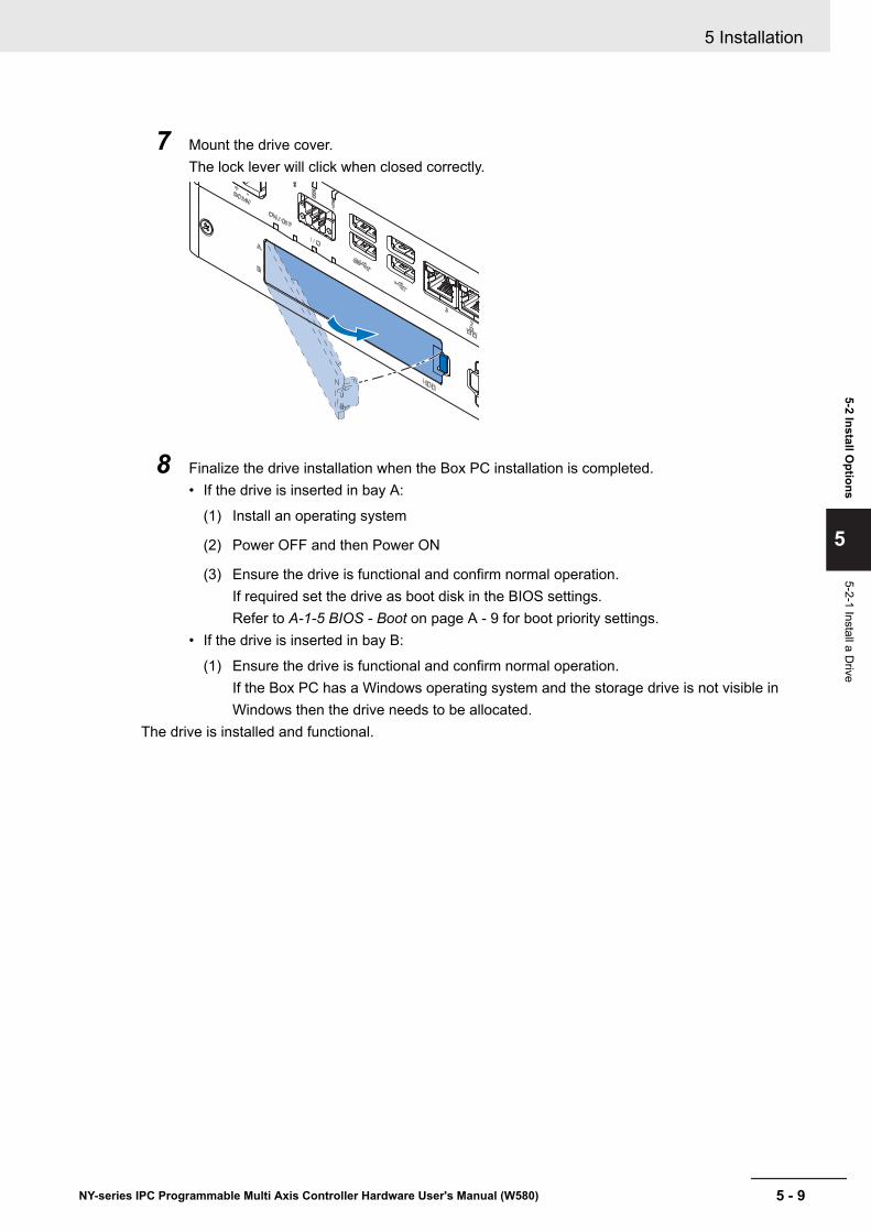
7 Mount the drive cover.The lock lever will click when closed correctly.
8 Finalize the drive installation when the Box PC installation is completed.• If the drive is inserted in bay A:
(1) Install an operating system
(2) Power OFF and then Power ON
(3) Ensure the drive is functional and confirm normal operation.If required set the drive as boot disk in the BIOS settings.Refer to A-1-5 BIOS - Boot on page A - 9 for boot priority settings.
• If the drive is inserted in bay B:
(1) Ensure the drive is functional and confirm normal operation.If the Box PC has a Windows operating system and the storage drive is not visible inWindows then the drive needs to be allocated.
The drive is installed and functional.
5 Installation
5 - 9NY-series IPC Programmable Multi Axis Controller Hardware User's Manual (W580)
5-2 Install Options
5
5-2-1 Install a Drive
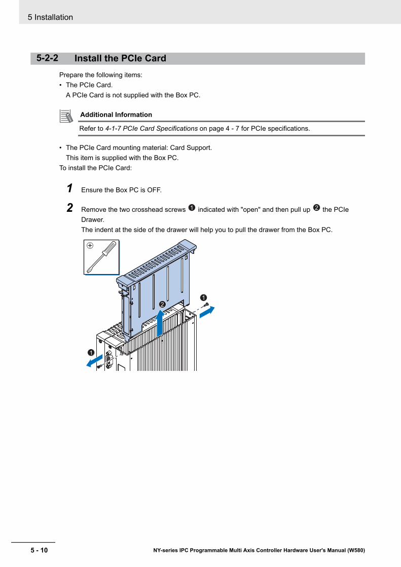
5-2-2 Install the PCIe CardPrepare the following items:• The PCIe Card.
A PCIe Card is not supplied with the Box PC.
Additional Information
Refer to 4-1-7 PCIe Card Specifications on page 4 - 7 for PCIe specifications.
• The PCIe Card mounting material: Card Support.This item is supplied with the Box PC.
To install the PCIe Card:
1 Ensure the Box PC is OFF.
2 Remove the two crosshead screws 1 indicated with "open" and then pull up 2 the PCIeDrawer.The indent at the side of the drawer will help you to pull the drawer from the Box PC.
2
1
1
5 Installation
5 - 10 NY-series IPC Programmable Multi Axis Controller Hardware User's Manual (W580)

3 Pull the middle of the Card Clip to unlock it and remove it from the PCIe Drawer.
2
1
4 Remove the slot cover from the PCIe Drawer.The thin sheet metal frame should stay in the PCIe Drawer.
2
1
The slot cover is now removed.
5 Installation
5 - 11NY-series IPC Programmable Multi Axis Controller Hardware User's Manual (W580)
5-2 Install Options
5
5-2-2 Install the PCIe C
ard
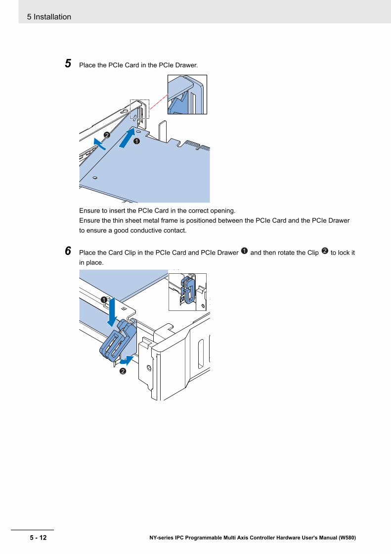
5 Place the PCIe Card in the PCIe Drawer.
1
2
Ensure to insert the PCIe Card in the correct opening.Ensure the thin sheet metal frame is positioned between the PCIe Card and the PCIe Drawerto ensure a good conductive contact.
6 Place the Card Clip in the PCIe Card and PCIe Drawer 1 and then rotate the Clip 2 to lock itin place.
1
2
5 Installation
5 - 12 NY-series IPC Programmable Multi Axis Controller Hardware User's Manual (W580)
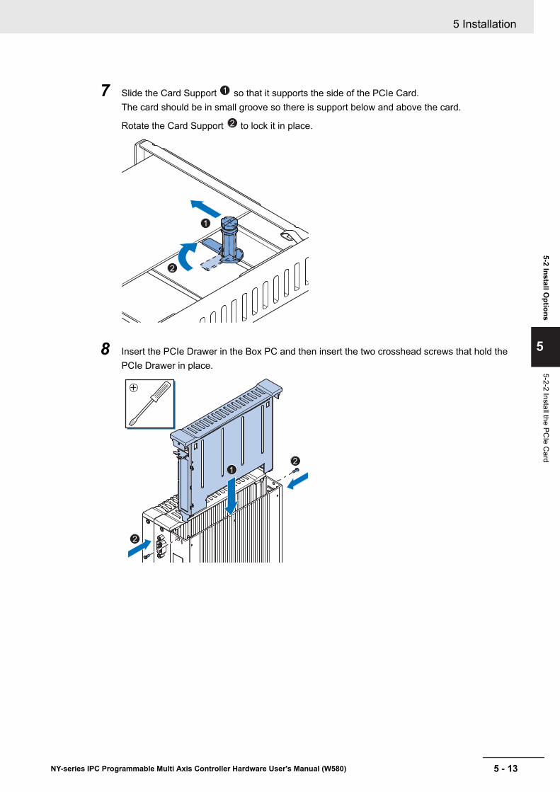
7 Slide the Card Support 1 so that it supports the side of the PCIe Card.The card should be in small groove so there is support below and above the card.
Rotate the Card Support 2 to lock it in place.
2
1
8 Insert the PCIe Drawer in the Box PC and then insert the two crosshead screws that hold thePCIe Drawer in place.
2
1
2
5 Installation
5 - 13NY-series IPC Programmable Multi Axis Controller Hardware User's Manual (W580)
5-2 Install Options
5
5-2-2 Install the PCIe C
ard
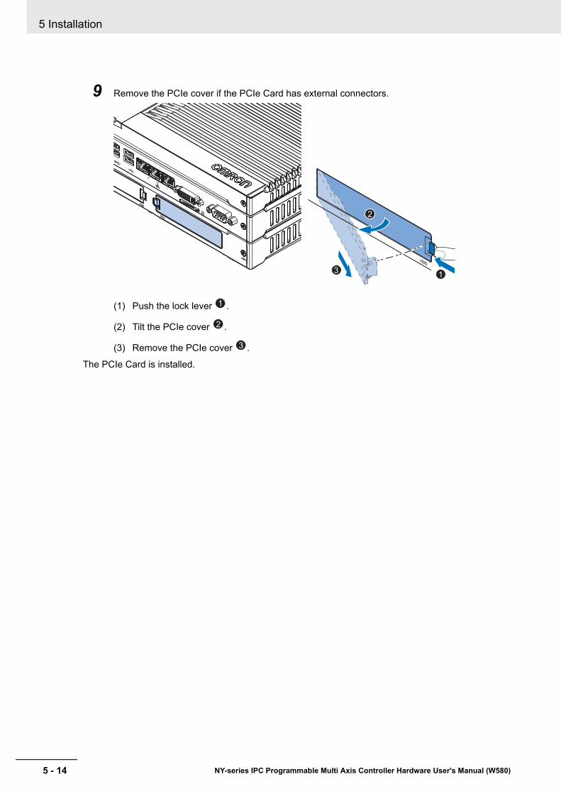
9 Remove the PCIe cover if the PCIe Card has external connectors.
1
3
2
(1) Push the lock lever 1 .
(2) Tilt the PCIe cover 2 .
(3) Remove the PCIe cover 3 .
The PCIe Card is installed.
5 Installation
5 - 14 NY-series IPC Programmable Multi Axis Controller Hardware User's Manual (W580)
5-3 MountThis section describes how to mount the Box PC in either a book or wall orientation inside a controlpanel.
WARNINGEnsure that installation and post-installation checks of the product areperformed by personnel in charge who possess a thorough understand-ing of the machinery to be installed.
5-3-1 Installation Method in Control PanelsThe IPC Programmable Multi Axis Controller must be mounted in a cabinet or a control panel.Consider the orientation, cooling distance, noise resistance, ducts and Box PC replacement when de-termining the space between the Box PC and other devices.
Precautions for Safe Use
Install the product in the correct orientation and temperature according to the specifications inthe manual to prevent overheating. Not doing so may result in malfunction.
Precautions for Correct Use
Do not operate or store the product in the following locations. Operation may stop or malfunc-tions may occur.• Locations subject to direct sunlight• Locations subject to temperatures or humidity outside the range specified in the specifica-
tions• Locations subject to condensation as the result of severe changes in temperature• Locations subject to corrosive or flammable gases• Locations subject to dust (especially iron dust) or salts• Locations subject to exposure to water, oil or chemicals• Locations subject to shock or vibration
Additional Information
• Ensure you have installed the options before you mount the product.Refer to 5-2 Install Options on page 5 - 6 for option details.
• Refer to 5-3-8 Book Mount Procedure on page 5 - 25or 5-3-9 Wall Mount Procedure on page 5 - 26 for orientation details.
• Refer to 5-3-3 Temperature on page 5 - 16 for temperature details.• Refer to 5-3-4 Humidity on page 5 - 19 for humidity details.• Refer to 5-4 Wire on page 5 - 27 for wiring details.
5 Installation
5 - 15NY-series IPC Programmable Multi Axis Controller Hardware User's Manual (W580)
5-3 Mount
5
5-3-1 Installation Method in C
ontrol Panels

5-3-2 Product Orientation
The Box PC can be mounted in a book A or wall B C orientation.
• For book mount there is one allowed orientation A .
• For wall mount there are two allowed orientations, horizontally mounted B and vertically mountedC .
Do not install the Box PC in other orientations.
A C
Book mount
Frontview Sideview
Wall mount
Frontview
Horizontal
Frontview
Vertical
Sideview
B
5-3-3 TemperatureThe temperature inside a control panel may be at least 10 to 15°C higher than outside the panel. Im-plement the following measures against overheating at the installation site and in the control panel,and allow a sufficient margin for the temperature.
Distance for CoolingAdequate airflow around the Industrial Box PC is required.
Additional Information
• The ambient temperature must be within the operating range.Refer to 4-4-1 Operation Environment Specifications on page 4 - 21 for temperature specifi-cations.
• Allow space to accommodate for the bending radius of the cables.Refer to:• 2-10-5 DVI Cables on page 2 - 21• 2-10-6 USB Type-A to USB Type-B Cables on page 2 - 21for cable bending requirements.
5 Installation
5 - 16 NY-series IPC Programmable Multi Axis Controller Hardware User's Manual (W580)
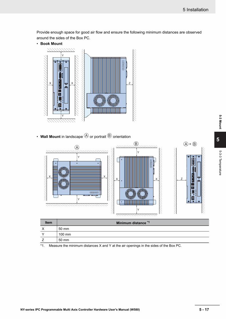
Provide enough space for good air flow and ensure the following minimum distances are observedaround the sides of the Box PC.• Book Mount
ZX X
Y
Y
• Wall Mount in landscape A or portrait B orientation
X X
X X
Y
Y
Y
Y
A
B B+A
Z
Item Minimum distance *1
X 50 mmY 100 mmZ 50 mm
*1. Measure the minimum distances X and Y at the air openings in the sides of the Box PC.
5 Installation
5 - 17NY-series IPC Programmable Multi Axis Controller Hardware User's Manual (W580)
5-3 Mount
5
5-3-3 Temperature
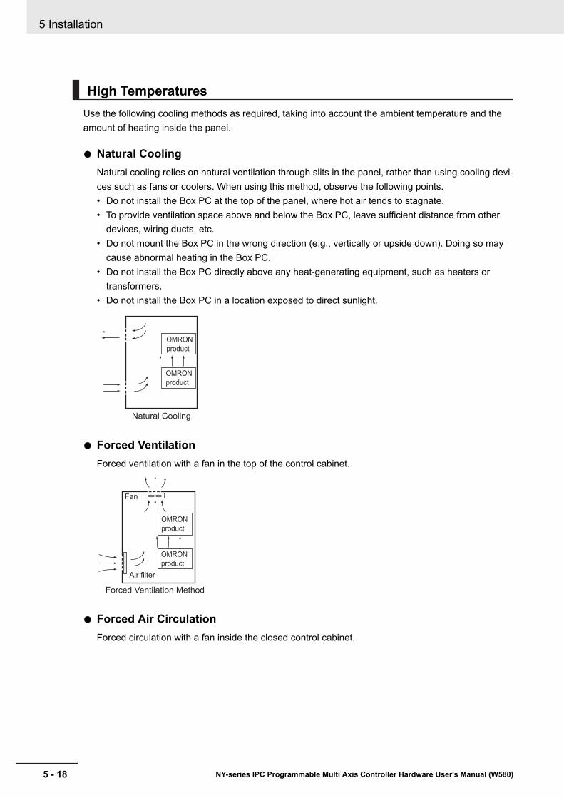
High TemperaturesUse the following cooling methods as required, taking into account the ambient temperature and theamount of heating inside the panel.
Natural CoolingNatural cooling relies on natural ventilation through slits in the panel, rather than using cooling devi-ces such as fans or coolers. When using this method, observe the following points.• Do not install the Box PC at the top of the panel, where hot air tends to stagnate.• To provide ventilation space above and below the Box PC, leave sufficient distance from other
devices, wiring ducts, etc.• Do not mount the Box PC in the wrong direction (e.g., vertically or upside down). Doing so may
cause abnormal heating in the Box PC.• Do not install the Box PC directly above any heat-generating equipment, such as heaters or
transformers.• Do not install the Box PC in a location exposed to direct sunlight.
Natural Cooling
OMRON
product
OMRON
product
Forced VentilationForced ventilation with a fan in the top of the control cabinet.
Air filter
Fan
Forced Ventilation Method
OMRON
product
OMRON
product
Forced Air CirculationForced circulation with a fan inside the closed control cabinet.
5 Installation
5 - 18 NY-series IPC Programmable Multi Axis Controller Hardware User's Manual (W580)
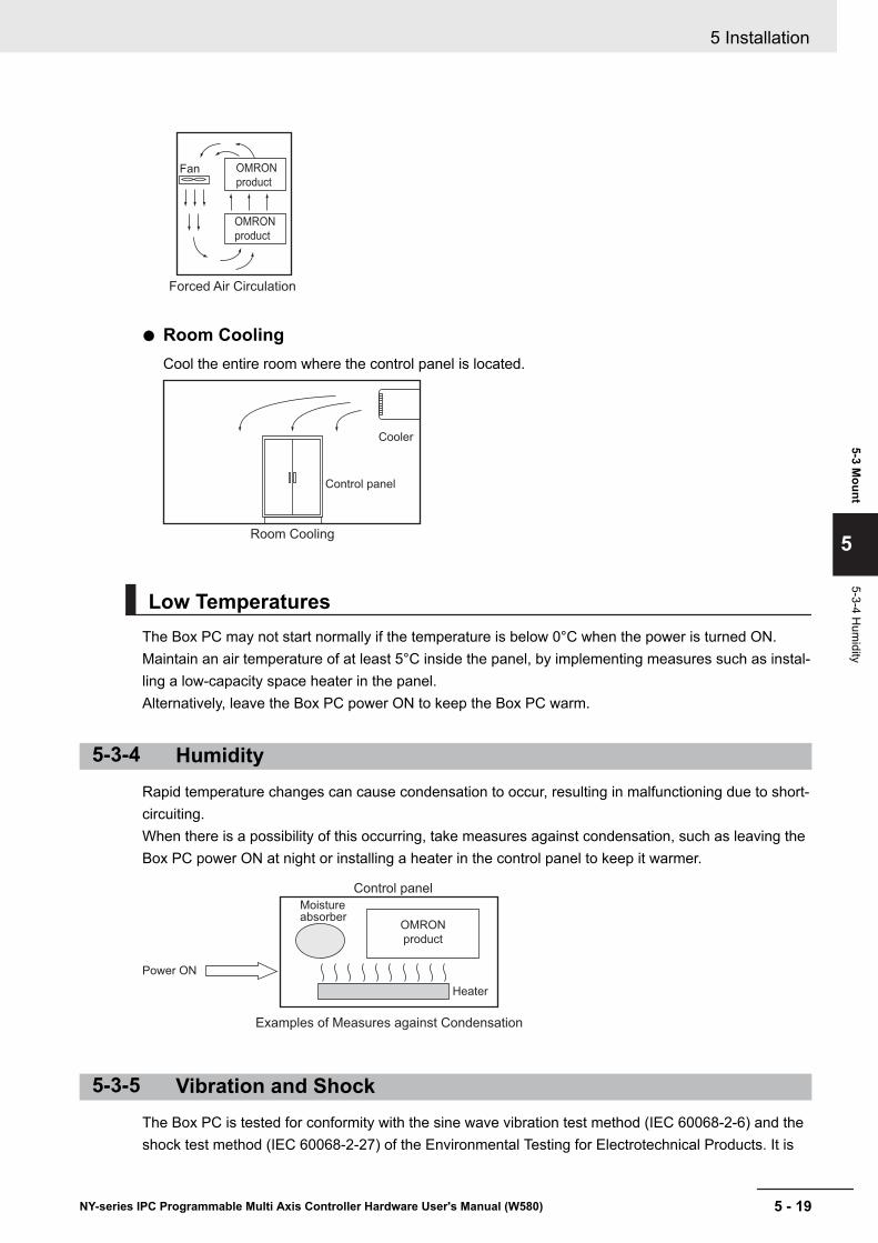
Fan
Forced Air Circulation
OMRON
product
OMRON
product
Room CoolingCool the entire room where the control panel is located.
Room Cooling
Cooler
Control panel
Low TemperaturesThe Box PC may not start normally if the temperature is below 0°C when the power is turned ON.Maintain an air temperature of at least 5°C inside the panel, by implementing measures such as instal-ling a low-capacity space heater in the panel.Alternatively, leave the Box PC power ON to keep the Box PC warm.
5-3-4 HumidityRapid temperature changes can cause condensation to occur, resulting in malfunctioning due to short-circuiting.When there is a possibility of this occurring, take measures against condensation, such as leaving theBox PC power ON at night or installing a heater in the control panel to keep it warmer.
Moistureabsorber
Power ON
Control panel
Heater
Examples of Measures against Condensation
OMRON
product
5-3-5 Vibration and ShockThe Box PC is tested for conformity with the sine wave vibration test method (IEC 60068-2-6) and theshock test method (IEC 60068-2-27) of the Environmental Testing for Electrotechnical Products. It is
5 Installation
5 - 19NY-series IPC Programmable Multi Axis Controller Hardware User's Manual (W580)
5-3 Mount
5
5-3-4 Hum
idity
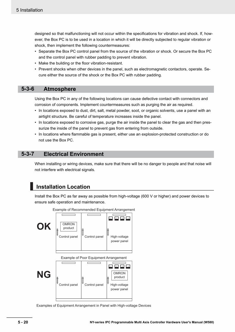
designed so that malfunctioning will not occur within the specifications for vibration and shock. If, how-ever, the Box PC is to be used in a location in which it will be directly subjected to regular vibration orshock, then implement the following countermeasures:• Separate the Box PC control panel from the source of the vibration or shock. Or secure the Box PC
and the control panel with rubber padding to prevent vibration.• Make the building or the floor vibration-resistant.• Prevent shocks when other devices in the panel, such as electromagnetic contactors, operate. Se-
cure either the source of the shock or the Box PC with rubber padding.
5-3-6 AtmosphereUsing the Box PC in any of the following locations can cause defective contact with connectors andcorrosion of components. Implement countermeasures such as purging the air as required.• In locations exposed to dust, dirt, salt, metal powder, soot, or organic solvents, use a panel with an
airtight structure. Be careful of temperature increases inside the panel.• In locations exposed to corrosive gas, purge the air inside the panel to clear the gas and then pres-
surize the inside of the panel to prevent gas from entering from outside.• In locations where flammable gas is present, either use an explosion-protected construction or do
not use the Box PC.
5-3-7 Electrical EnvironmentWhen installing or wiring devices, make sure that there will be no danger to people and that noise willnot interfere with electrical signals.
Installation LocationInstall the Box PC as far away as possible from high-voltage (600 V or higher) and power devices toensure safe operation and maintenance.
Example of Recommended Equipment Arrangement
Control panel Control panel High-voltage
power panel
Examples of Equipment Arrangement in Panel with High-voltage Devices
Example of Poor Equipment Arrangement
Control panel Control panel
OMRON
productOK
NGOMRON
product
High-voltage
power panel
5 Installation
5 - 20 NY-series IPC Programmable Multi Axis Controller Hardware User's Manual (W580)
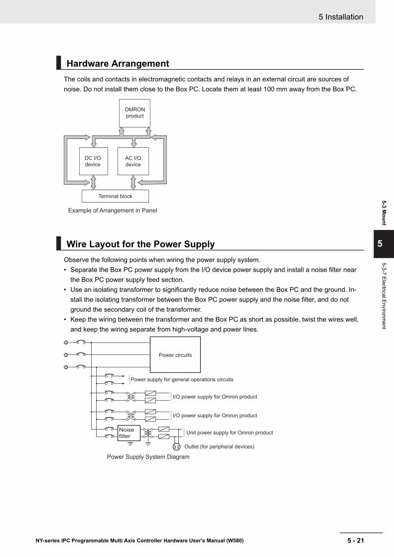
Hardware ArrangementThe coils and contacts in electromagnetic contacts and relays in an external circuit are sources ofnoise. Do not install them close to the Box PC. Locate them at least 100 mm away from the Box PC.
Example of Arrangement in Panel
AC I/O
device
Terminal block
DC I/O
device
OMRON
product
Wire Layout for the Power SupplyObserve the following points when wiring the power supply system.• Separate the Box PC power supply from the I/O device power supply and install a noise filter near
the Box PC power supply feed section.• Use an isolating transformer to significantly reduce noise between the Box PC and the ground. In-
stall the isolating transformer between the Box PC power supply and the noise filter, and do notground the secondary coil of the transformer.
• Keep the wiring between the transformer and the Box PC as short as possible, twist the wires well,and keep the wiring separate from high-voltage and power lines.
Unit power supply for Omron product
I/O power supply for Omron product
Power Supply System Diagram
Power circuits
Power supply for general operations circuits
Outlet (for peripheral devices)
I/O power supply for Omron product
Noise
filter
5 Installation
5 - 21NY-series IPC Programmable Multi Axis Controller Hardware User's Manual (W580)
5-3 Mount
5
5-3-7 Electrical Environment
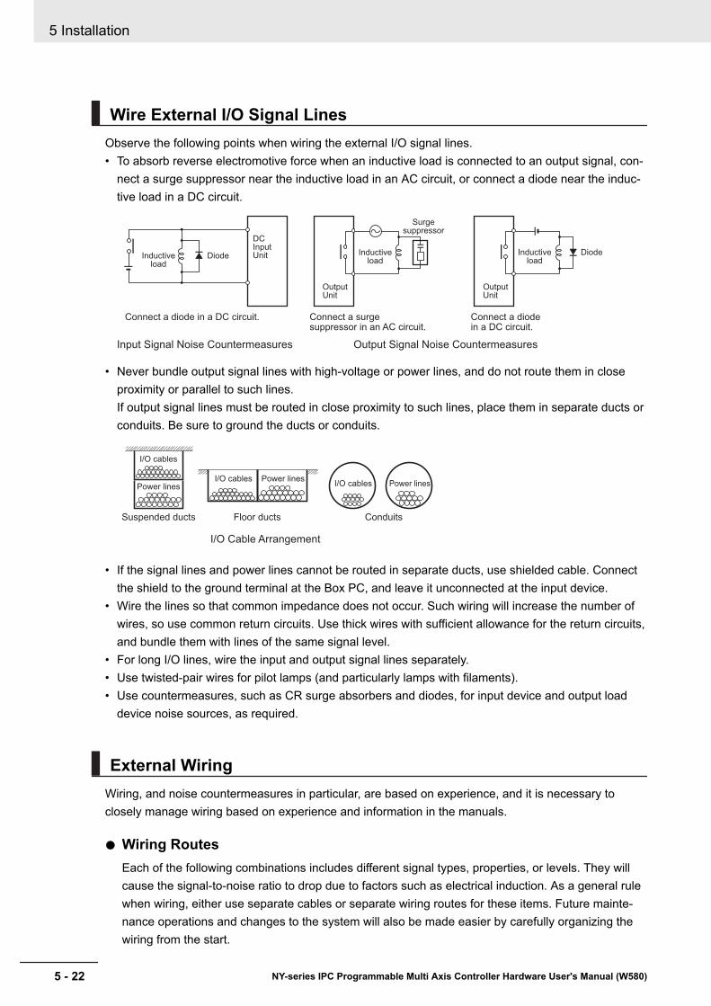
Wire External I/O Signal LinesObserve the following points when wiring the external I/O signal lines.• To absorb reverse electromotive force when an inductive load is connected to an output signal, con-
nect a surge suppressor near the inductive load in an AC circuit, or connect a diode near the induc-tive load in a DC circuit.
Input Signal Noise Countermeasures
DCInputUnitInductive
loadDiode
Connect a diode in a DC circuit.
Output Signal Noise Countermeasures
OutputUnit
OutputUnit
Connect a diodein a DC circuit.
Connect a surgesuppressor in an AC circuit.
Inductiveload
DiodeInductiveload
Surgesuppressor
• Never bundle output signal lines with high-voltage or power lines, and do not route them in closeproximity or parallel to such lines.If output signal lines must be routed in close proximity to such lines, place them in separate ducts orconduits. Be sure to ground the ducts or conduits.
I/O Cable Arrangement
Floor ducts ConduitsSuspended ducts
I/O cables
I/O cablesPower lines
Power linesI/O cables Power lines
• If the signal lines and power lines cannot be routed in separate ducts, use shielded cable. Connectthe shield to the ground terminal at the Box PC, and leave it unconnected at the input device.
• Wire the lines so that common impedance does not occur. Such wiring will increase the number ofwires, so use common return circuits. Use thick wires with sufficient allowance for the return circuits,and bundle them with lines of the same signal level.
• For long I/O lines, wire the input and output signal lines separately.• Use twisted-pair wires for pilot lamps (and particularly lamps with filaments).• Use countermeasures, such as CR surge absorbers and diodes, for input device and output load
device noise sources, as required.
External WiringWiring, and noise countermeasures in particular, are based on experience, and it is necessary toclosely manage wiring based on experience and information in the manuals.
Wiring RoutesEach of the following combinations includes different signal types, properties, or levels. They willcause the signal-to-noise ratio to drop due to factors such as electrical induction. As a general rulewhen wiring, either use separate cables or separate wiring routes for these items. Future mainte-nance operations and changes to the system will also be made easier by carefully organizing thewiring from the start.
5 Installation
5 - 22 NY-series IPC Programmable Multi Axis Controller Hardware User's Manual (W580)

• Power lines and signal lines• Input signals and output signals• Analog signals and digital signals• High-level signals and low-level signals• Communications lines and power lines• DC signals and AC signals• High-frequency devices (such as Inverters) and signal lines (communications)
(Routing of) WiringObserve the following points when wiring power supply and signal cables.• When routing signal cables with differing characteristics through the same duct, always keep
them separated.• As much as possible, avoid routing multiple power supply lines through the same duct. If it can-
not be avoided, then construct a partition between them in the duct and ground the partition.
Partitioning Methods for Signal and Power Supply Cables
(a) (b)
(c) (d)
Signal cables
Signal cables
Signal cables
Power supply cables
a
Power supply cables
Partition
Signalcables
(group A)
Signalcables
(group B)
Signalcables
(group C)
• To avoid overheating the conduits when using conduits for wiring, do not place wires for a singlecircuit in separate conduits.
Parallel Wiring (Single Phase)
Correct
Correct
Power supply
Incorrect
Power supply
Power supply
Load
Load
Load
Conduits
Conduits
Conduits
NG
OK
OK
5 Installation
5 - 23NY-series IPC Programmable Multi Axis Controller Hardware User's Manual (W580)
5-3 Mount
5
5-3-7 Electrical Environment

• Power cables and signal cables adversely affect each other. Do not wire them in parallel.• Noise induction may occur if the Box PC is installed in a panel that includes high-voltage devi-
ces. Wire and install them as far apart as possible.• Either install the Box PC a minimum of 200 mm away from high-voltage lines or power lines, or
place the high-voltage lines or power lines in metal tubing and completely ground the metal tub-ing to 100 Ω or less.
Example: Separating an OMRON product from Power Lines
Metal tubing
200 mm
200 mm
High-voltage power panel
Power lines
Power lines
Ground of 100 Ω or less
OMRON
product
OMRON
product
Wiring DuctsWhenever possible, route the cables and wires through wiring ducts.Install the wiring ducts so that it is easy to route the wires from the IPC Programmable Multi AxisController directly into the duct.
Additional Information
Refer to Distance for Cooling on page 5 - 16 for the minimum required distances.
It is convenient to use wiring ducts that have the same depth as the IPC Programmable Multi AxisController.
Duct
Product
Other PrecautionsBasic I/O Units have both plus and minus commons, so pay attention to the polarity when wiring.
5 Installation
5 - 24 NY-series IPC Programmable Multi Axis Controller Hardware User's Manual (W580)
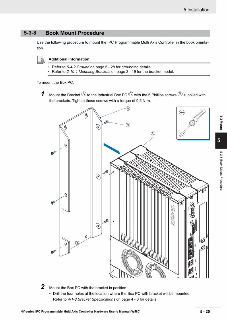
5-3-8 Book Mount ProcedureUse the following procedure to mount the IPC Programmable Multi Axis Controller in the book orienta-tion.
Additional Information
• Refer to 5-4-2 Ground on page 5 - 28 for grounding details.• Refer to 2-10-1 Mounting Brackets on page 2 - 19 for the bracket model.
To mount the Box PC:
1 Mount the Bracket A to the Industrial Box PC C with the 6 Phillips screws B supplied withthe brackets. Tighten these screws with a torque of 0.5 N·m.
A
B
C
0
15
2 Mount the Box PC with the bracket in position.• Drill the four holes at the location where the Box PC with bracket will be mounted.
Refer to 4-1-8 Bracket Specifications on page 4 - 8 for details.
5 Installation
5 - 25NY-series IPC Programmable Multi Axis Controller Hardware User's Manual (W580)
5-3 Mount
5
5-3-8 Book Mount Procedure
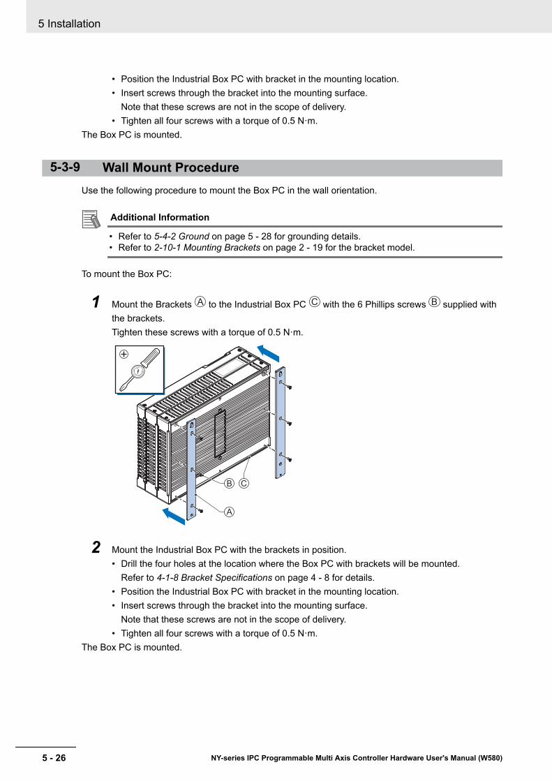
• Position the Industrial Box PC with bracket in the mounting location.• Insert screws through the bracket into the mounting surface.
Note that these screws are not in the scope of delivery.• Tighten all four screws with a torque of 0.5 N·m.
The Box PC is mounted.
5-3-9 Wall Mount ProcedureUse the following procedure to mount the Box PC in the wall orientation.
Additional Information
• Refer to 5-4-2 Ground on page 5 - 28 for grounding details.• Refer to 2-10-1 Mounting Brackets on page 2 - 19 for the bracket model.
To mount the Box PC:
1 Mount the Brackets A to the Industrial Box PC C with the 6 Phillips screws B supplied withthe brackets.Tighten these screws with a torque of 0.5 N·m.
A
B C
0
15
2 Mount the Industrial Box PC with the brackets in position.• Drill the four holes at the location where the Box PC with brackets will be mounted.
Refer to 4-1-8 Bracket Specifications on page 4 - 8 for details.• Position the Industrial Box PC with bracket in the mounting location.• Insert screws through the bracket into the mounting surface.
Note that these screws are not in the scope of delivery.• Tighten all four screws with a torque of 0.5 N·m.
The Box PC is mounted.
5 Installation
5 - 26 NY-series IPC Programmable Multi Axis Controller Hardware User's Manual (W580)
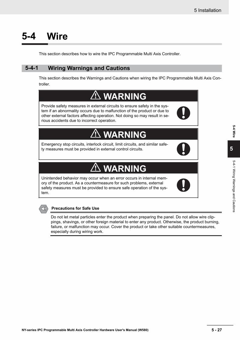
5-4 WireThis section describes how to wire the IPC Programmable Multi Axis Controller.
5-4-1 Wiring Warnings and CautionsThis section describes the Warnings and Cautions when wiring the IPC Programmable Multi Axis Con-troller.
WARNINGProvide safety measures in external circuits to ensure safety in the sys-tem if an abnormality occurs due to malfunction of the product or due toother external factors affecting operation. Not doing so may result in se-rious accidents due to incorrect operation.
WARNINGEmergency stop circuits, interlock circuit, limit circuits, and similar safe-ty measures must be provided in external control circuits.
WARNINGUnintended behavior may occur when an error occurs in internal mem-ory of the product. As a countermeasure for such problems, externalsafety measures must be provided to ensure safe operation of the sys-tem.
Precautions for Safe Use
Do not let metal particles enter the product when preparing the panel. Do not allow wire clip-pings, shavings, or other foreign material to enter any product. Otherwise, the product burning,failure, or malfunction may occur. Cover the product or take other suitable countermeasures,especially during wiring work.
5 Installation
5 - 27NY-series IPC Programmable Multi Axis Controller Hardware User's Manual (W580)
5-4 Wire
5
5-4-1 Wiring W
arnings and Cautions
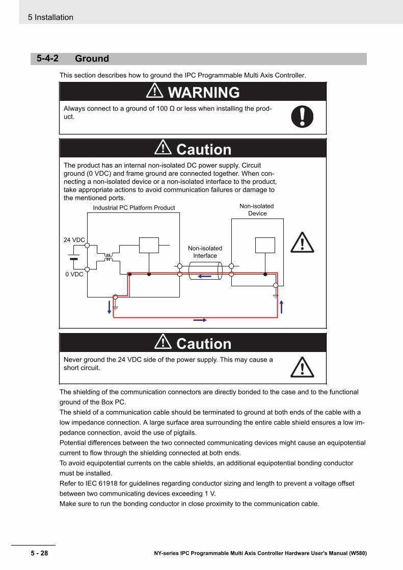
5-4-2 GroundThis section describes how to ground the IPC Programmable Multi Axis Controller.
WARNINGAlways connect to a ground of 100 Ω or less when installing the prod-uct.
CautionThe product has an internal non-isolated DC power supply. Circuitground (0 VDC) and frame ground are connected together. When con-necting a non-isolated device or a non-isolated interface to the product,take appropriate actions to avoid communication failures or damage tothe mentioned ports.
Industrial PC Platform Product Non-isolated
Device
Non-isolated
Interface
24 VDC
0 VDC
CautionNever ground the 24 VDC side of the power supply. This may cause ashort circuit.
The shielding of the communication connectors are directly bonded to the case and to the functionalground of the Box PC.The shield of a communication cable should be terminated to ground at both ends of the cable with alow impedance connection. A large surface area surrounding the entire cable shield ensures a low im-pedance connection, avoid the use of pigtails.Potential differences between the two connected communicating devices might cause an equipotentialcurrent to flow through the shielding connected at both ends.To avoid equipotential currents on the cable shields, an additional equipotential bonding conductormust be installed.Refer to IEC 61918 for guidelines regarding conductor sizing and length to prevent a voltage offsetbetween two communicating devices exceeding 1 V.Make sure to run the bonding conductor in close proximity to the communication cable.
5 Installation
5 - 28 NY-series IPC Programmable Multi Axis Controller Hardware User's Manual (W580)

Considerations for Earthing MethodsLocal potential fluctuations due to lightning or noise occurred by power devices will cause potentialfluctuations between ground terminals of devices. This potential fluctuation may result in device mal-function or damage. To prevent this, it is necessary to suppress the occurrence of a difference in elec-trical potential between ground terminals of devices. You need to consider the earthing methods toachieve this objective.
The recommended earthing methods for each usage condition are given in the following table.
Specification of commu-nications cables
Earthing methodsEquipotential bonding
system Star earthing Daisy chain
The cable shield connect-ed to the connector hoodat both ends of the com-munications cable
Recommended Not recommended Not recommended
Additional Information
• In a country or region where the earthing method is regulated, you must comply with the reg-ulations. Refer to the applicable local and national ordinances of the place where you installthe system, or other international laws and regulations.
• Ethernet switches are used with the EtherNet/IP. For information on the environmental resist-ance of the Ethernet switch to use, the grounding between Ethernet switches, or the specifi-cations of cables, ask the Ethernet switch manufacturer.
Each of these earthing methods is given below.
5 Installation
5 - 29NY-series IPC Programmable Multi Axis Controller Hardware User's Manual (W580)
5-4 Wire
5
5-4-2 Ground
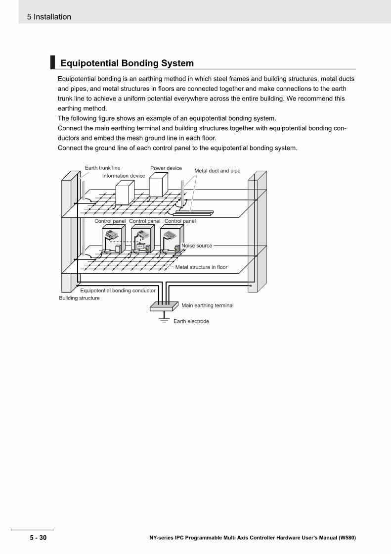
Equipotential Bonding SystemEquipotential bonding is an earthing method in which steel frames and building structures, metal ductsand pipes, and metal structures in floors are connected together and make connections to the earthtrunk line to achieve a uniform potential everywhere across the entire building. We recommend thisearthing method.The following figure shows an example of an equipotential bonding system.Connect the main earthing terminal and building structures together with equipotential bonding con-ductors and embed the mesh ground line in each floor.Connect the ground line of each control panel to the equipotential bonding system.
Information device
Power deviceMetal duct and pipe
Building structure
Equipotential bonding conductor
Main earthing terminal
Earth electrode
Metal structure in floor
Earth trunk line
Control panel Control panel Control panel
Hub Noise source
5 Installation
5 - 30 NY-series IPC Programmable Multi Axis Controller Hardware User's Manual (W580)
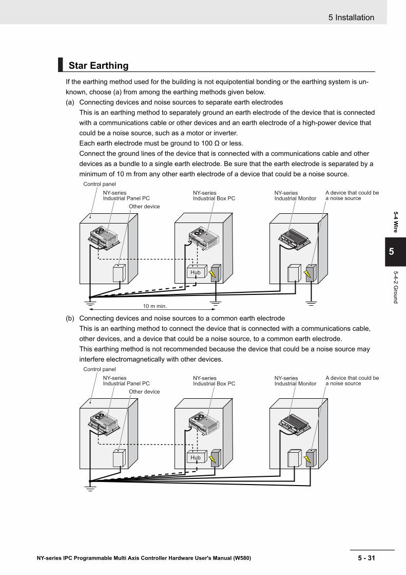
Star EarthingIf the earthing method used for the building is not equipotential bonding or the earthing system is un-known, choose (a) from among the earthing methods given below.(a) Connecting devices and noise sources to separate earth electrodes
This is an earthing method to separately ground an earth electrode of the device that is connectedwith a communications cable or other devices and an earth electrode of a high-power device thatcould be a noise source, such as a motor or inverter.Each earth electrode must be ground to 100 Ω or less.Connect the ground lines of the device that is connected with a communications cable and otherdevices as a bundle to a single earth electrode. Be sure that the earth electrode is separated by aminimum of 10 m from any other earth electrode of a device that could be a noise source.
Hub
Control panel
Other device
A device that could be a noise source
NY-seriesIndustrial Box PC
NY-seriesIndustrial Panel PC
NY-seriesIndustrial Monitor
10 m min.
(b) Connecting devices and noise sources to a common earth electrodeThis is an earthing method to connect the device that is connected with a communications cable,other devices, and a device that could be a noise source, to a common earth electrode.This earthing method is not recommended because the device that could be a noise source mayinterfere electromagnetically with other devices.
Hub
Control panel
Other device
A device that could be a noise source
NY-seriesIndustrial Box PC
NY-seriesIndustrial Panel PC
NY-seriesIndustrial Monitor
5 Installation
5 - 31NY-series IPC Programmable Multi Axis Controller Hardware User's Manual (W580)
5-4 Wire
5
5-4-2 Ground
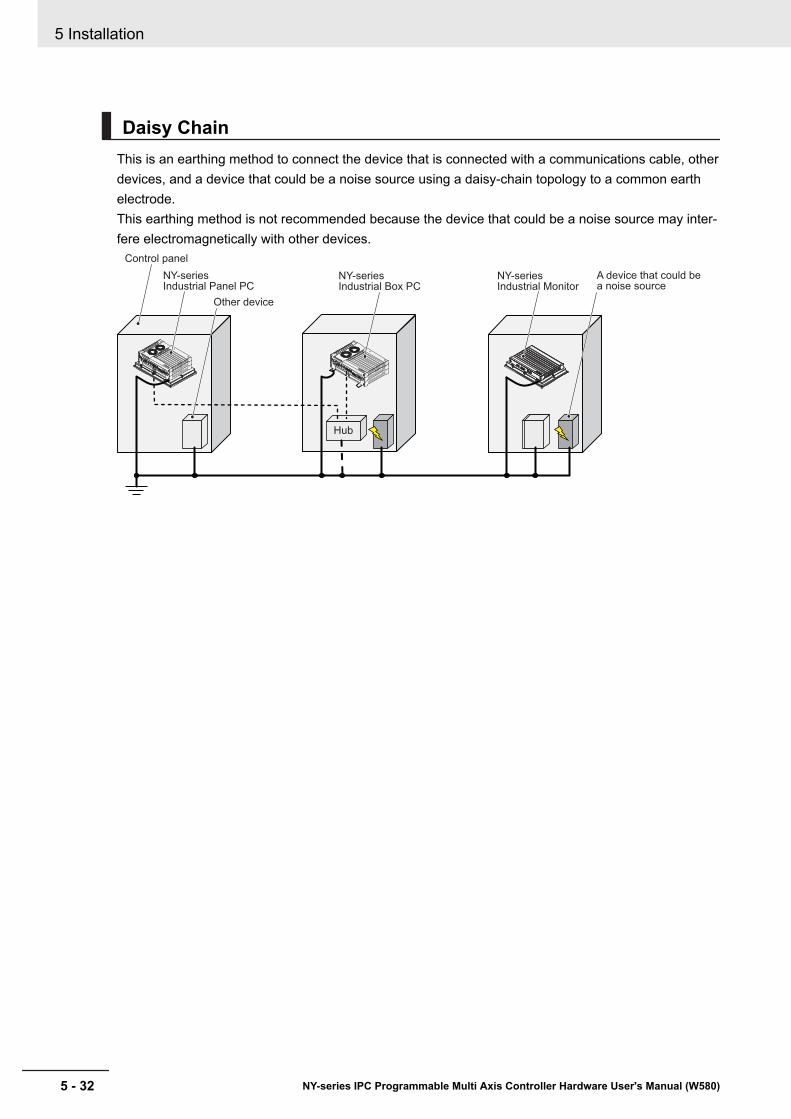
Daisy ChainThis is an earthing method to connect the device that is connected with a communications cable, otherdevices, and a device that could be a noise source using a daisy-chain topology to a common earthelectrode.This earthing method is not recommended because the device that could be a noise source may inter-fere electromagnetically with other devices.
Hub
Control panel
Other device
A device that could be a noise source
NY-seriesIndustrial Box PC
NY-seriesIndustrial Panel PC
NY-seriesIndustrial Monitor
5 Installation
5 - 32 NY-series IPC Programmable Multi Axis Controller Hardware User's Manual (W580)
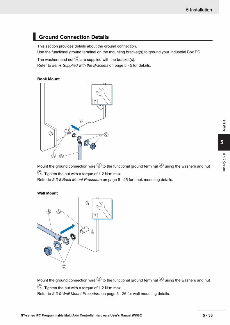
Ground Connection DetailsThis section provides details about the ground connection.Use the functional ground terminal on the mounting bracket(s) to ground your Industrial Box PC.
The washers and nut C are supplied with the bracket(s).Refer to Items Supplied with the Brackets on page 5 - 5 for details.
Book Mount
7
BA
C
Mount the ground connection wire B to the functional ground terminal A using the washers and nutC . Tighten the nut with a torque of 1.2 N·m max.Refer to 5-3-8 Book Mount Procedure on page 5 - 25 for book mounting details.
Wall Mount
7
B A
C
Mount the ground connection wire B to the functional ground terminal A using the washers and nutC . Tighten the nut with a torque of 1.2 N·m max.Refer to 5-3-9 Wall Mount Procedure on page 5 - 26 for wall mounting details.
5 Installation
5 - 33NY-series IPC Programmable Multi Axis Controller Hardware User's Manual (W580)
5-4 Wire
5
5-4-2 Ground
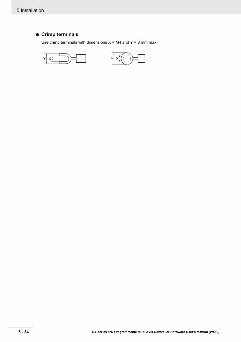
Crimp terminalsUse crimp terminals with dimensions X = M4 and Y = 8 mm max.
Y X Y X
5 Installation
5 - 34 NY-series IPC Programmable Multi Axis Controller Hardware User's Manual (W580)
5-4-3 Wire the Power ConnectorThis section describes how to wire the power connector.
Precautions for Safe Use
• Do not perform a dielectric strength test.• Always use the recommended uninterruptible power supply (UPS) to prevent data loss and
other system file integrity issues caused by unexpected power interruption. Back up the sys-tem files in the planned way to prevent data loss and other system file integrity issues causedby incorrect operation.
Additional Information
• The selected conductor size must match with the used maximum power supply capacity or anovercurrent protection device must be used.
• The used wires and the overcurrent protection device must meet the applicable nationalstandards.Standards are:• NEC (National Electric Code)• CEC (Canadian Electrical Code)• international applicable standards
• Refer to 4-1-2 General Electrical Specifications on page 4 - 3 for electrical specifications.• Refer to 4-1-3 Power Consumption Specifications on page 4 - 4 for power consumption spec-
ifications.• Refer to 2-10-9 UPS on page 2 - 23 for UPS information.
5 Installation
5 - 35NY-series IPC Programmable Multi Axis Controller Hardware User's Manual (W580)
5-4 Wire
5
5-4-3 Wire the Pow
er Connector
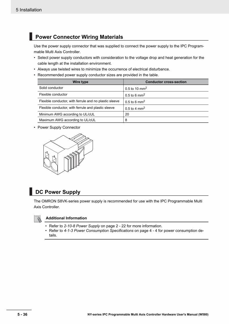
Power Connector Wiring MaterialsUse the power supply connector that was supplied to connect the power supply to the IPC Program-mable Multi Axis Controller.• Select power supply conductors with consideration to the voltage drop and heat generation for the
cable length at the installation environment.• Always use twisted wires to minimize the occurrence of electrical disturbance.• Recommended power supply conductor sizes are provided in the table.
Wire type Conductor cross-sectionSolid conductor 0.5 to 10 mm2
Flexible conductor 0.5 to 6 mm2
Flexible conductor, with ferrule and no plastic sleeve 0.5 to 6 mm2
Flexible conductor, with ferrule and plastic sleeve 0.5 to 4 mm2
Minimum AWG according to UL/cUL 20Maximum AWG according to UL/cUL 8
• Power Supply Connector
DC Power SupplyThe OMRON S8VK-series power supply is recommended for use with the IPC Programmable MultiAxis Controller.
Additional Information
• Refer to 2-10-8 Power Supply on page 2 - 22 for more information.• Refer to 4-1-3 Power Consumption Specifications on page 4 - 4 for power consumption de-
tails.
5 Installation
5 - 36 NY-series IPC Programmable Multi Axis Controller Hardware User's Manual (W580)

Power Connector Wiring ProcedureUse the following procedure to wire the power connector.
1 Remove the sheath from the power supply wires.7 mm
Precautions for Safe Use
Observe the following precautions to prevent broken wires.• When you remove the sheath, be careful not to damage the conductor.• Connect the conductor without twisting the wires.• Do not weld the conductors. Doing so may cause the wires to break with vibration.
2 Insert a screwdriver in the small opening above the cable opening 1 to unlock the cable entry
and then push the wire all the way to the back of the cable opening 2 .
21
1
2
Pin Description1 24 VDC2 0 VDC
3 Remove the screwdriver.Do not apply stress to the cable after you have connected the wires.
5 Installation
5 - 37NY-series IPC Programmable Multi Axis Controller Hardware User's Manual (W580)
5-4 Wire
5
5-4-3 Wire the Pow
er Connector
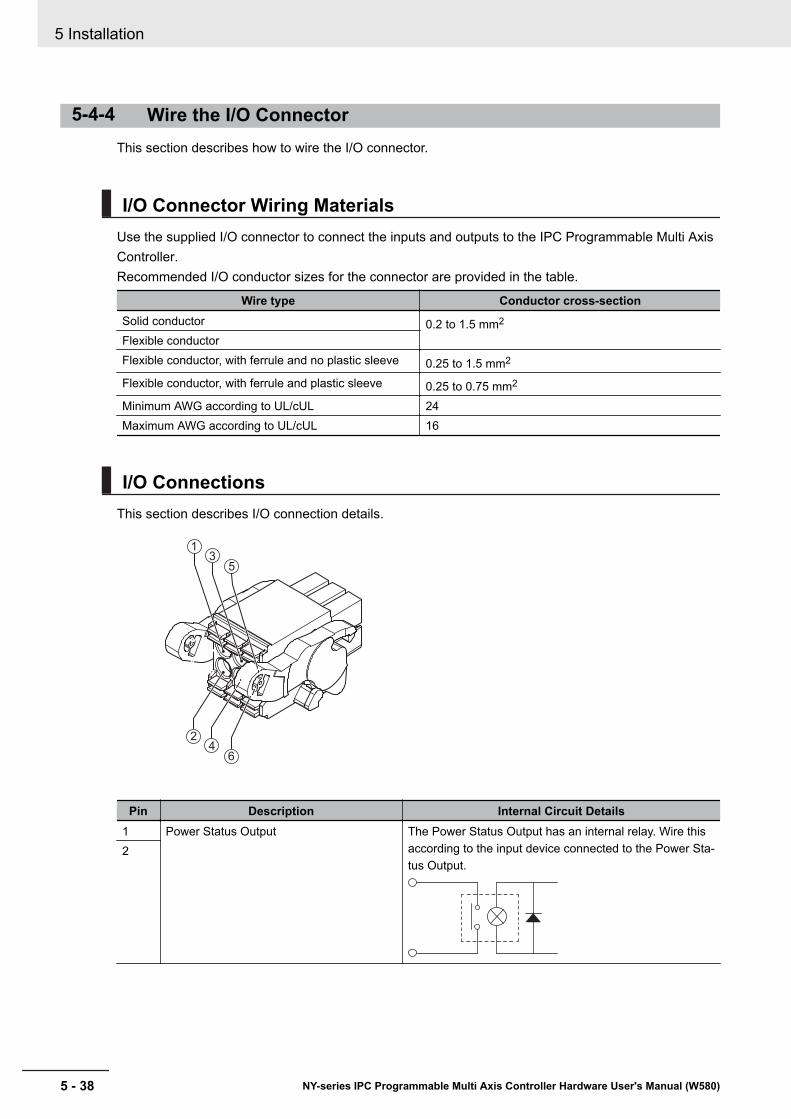
5-4-4 Wire the I/O ConnectorThis section describes how to wire the I/O connector.
I/O Connector Wiring MaterialsUse the supplied I/O connector to connect the inputs and outputs to the IPC Programmable Multi AxisController.Recommended I/O conductor sizes for the connector are provided in the table.
Wire type Conductor cross-sectionSolid conductor 0.2 to 1.5 mm2
Flexible conductorFlexible conductor, with ferrule and no plastic sleeve 0.25 to 1.5 mm2
Flexible conductor, with ferrule and plastic sleeve 0.25 to 0.75 mm2
Minimum AWG according to UL/cUL 24Maximum AWG according to UL/cUL 16
I/O ConnectionsThis section describes I/O connection details.
1
3
5
2
4
6
Pin Description Internal Circuit Details1 Power Status Output The Power Status Output has an internal relay. Wire this
according to the input device connected to the Power Sta-tus Output.
2
5 Installation
5 - 38 NY-series IPC Programmable Multi Axis Controller Hardware User's Manual (W580)
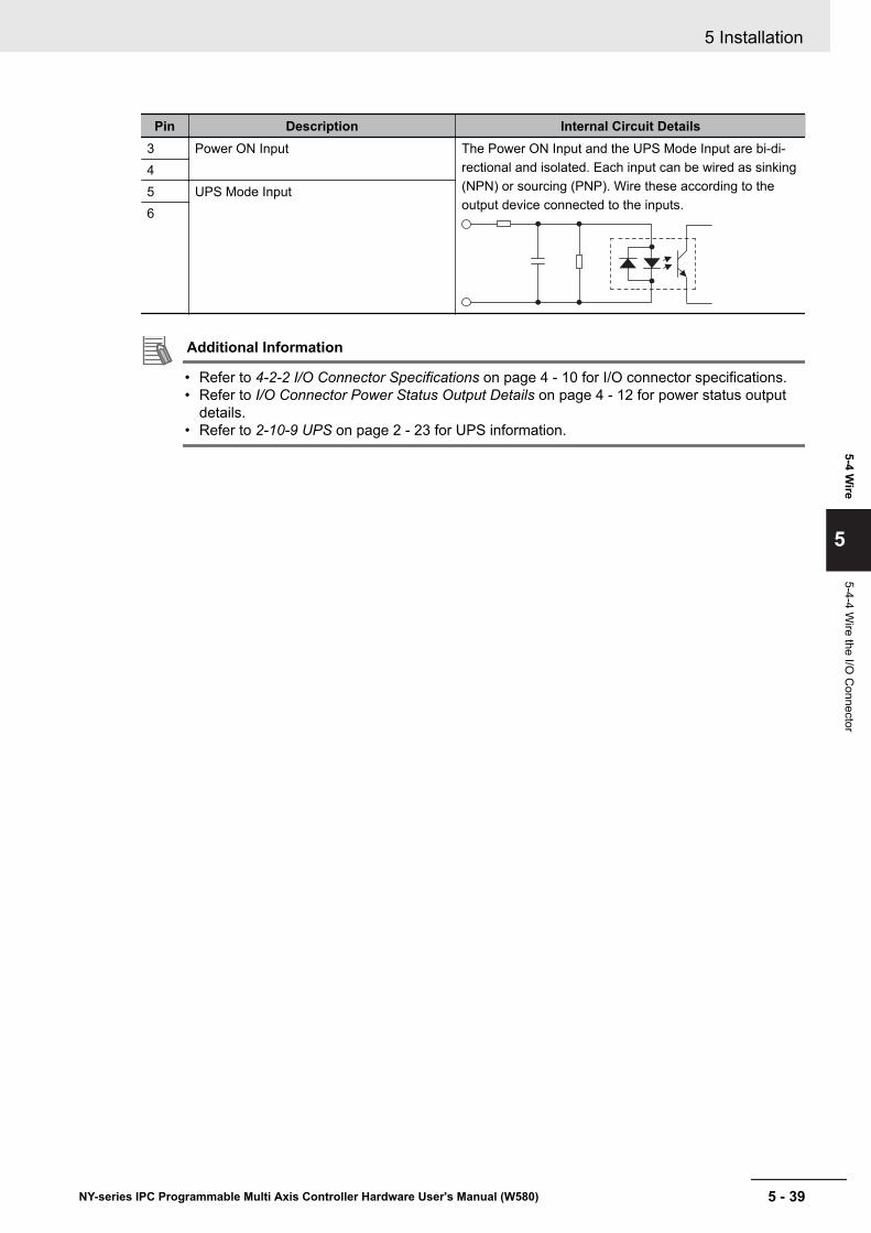
Pin Description Internal Circuit Details3 Power ON Input The Power ON Input and the UPS Mode Input are bi-di-
rectional and isolated. Each input can be wired as sinking(NPN) or sourcing (PNP). Wire these according to theoutput device connected to the inputs.
45 UPS Mode Input6
Additional Information
• Refer to 4-2-2 I/O Connector Specifications on page 4 - 10 for I/O connector specifications.• Refer to I/O Connector Power Status Output Details on page 4 - 12 for power status output
details.• Refer to 2-10-9 UPS on page 2 - 23 for UPS information.
5 Installation
5 - 39NY-series IPC Programmable Multi Axis Controller Hardware User's Manual (W580)
5-4 Wire
5
5-4-4 Wire the I/O
Connector

I/O Connector Wiring ProcedureUse the following procedure to wire the I/O connector.
1 Remove the sheath from the wires.7 mm
Precautions for Safe Use
Observe the following precautions to prevent broken wires.• When you remove the sheath, be careful not to damage the conductor.• Connect the conductor without twisting the wires.• Do not weld the conductors. Doing so may cause the wires to break with vibration.
2 Remove the I/O connector from the Box PC.
3 Insert a screwdriver in the small groove above the cable entry 1 to unlock the cable entry and
then push the wire all the way to the back of the cable opening 2 .
1
2
4 Remove the screwdriver.Do not apply stress to the cable after you have connected the wires.
5 Installation
5 - 40 NY-series IPC Programmable Multi Axis Controller Hardware User's Manual (W580)
5-5 ConnectThis section describes how to connect the IPC Programmable Multi Axis Controller.
5 Installation
5 - 41NY-series IPC Programmable Multi Axis Controller Hardware User's Manual (W580)
5-5 Connect
5
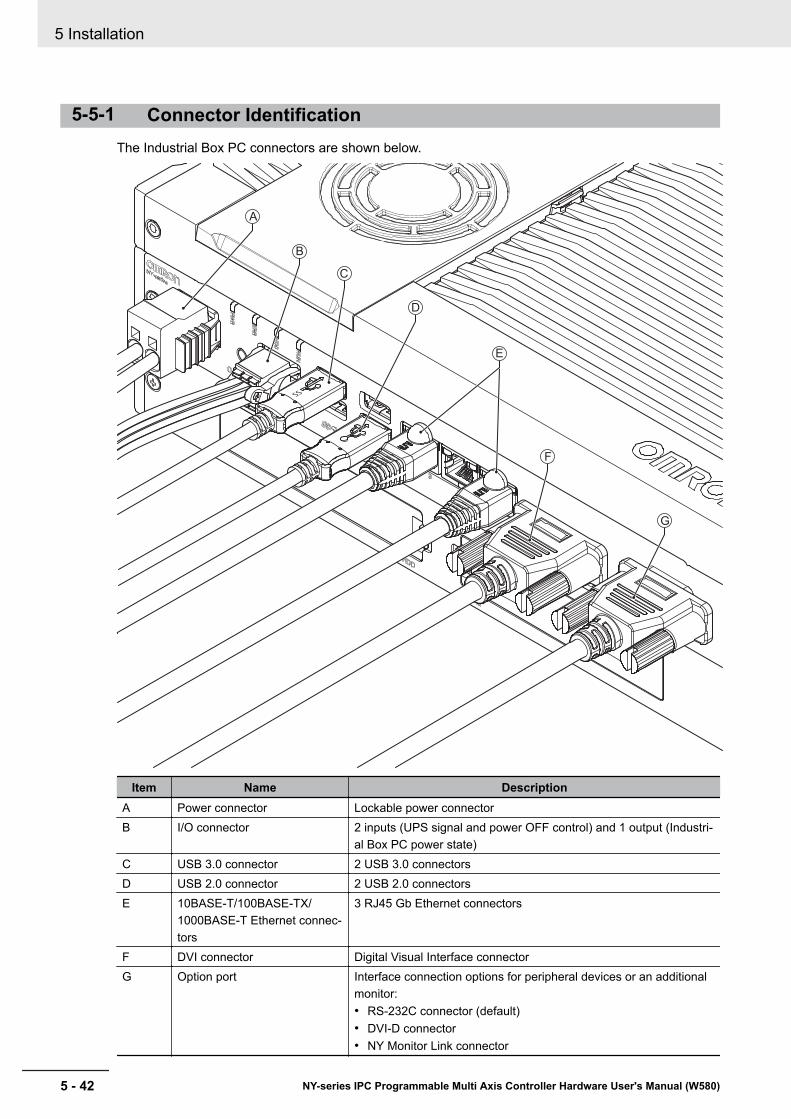
5-5-1 Connector IdentificationThe Industrial Box PC connectors are shown below.
A
D
E
B
C
G
F
Item Name DescriptionA Power connector Lockable power connectorB I/O connector 2 inputs (UPS signal and power OFF control) and 1 output (Industri-
al Box PC power state)C USB 3.0 connector 2 USB 3.0 connectorsD USB 2.0 connector 2 USB 2.0 connectorsE 10BASE-T/100BASE-TX/
1000BASE-T Ethernet connec-tors
3 RJ45 Gb Ethernet connectors
F DVI connector Digital Visual Interface connectorG Option port Interface connection options for peripheral devices or an additional
monitor:• RS-232C connector (default)• DVI-D connector• NY Monitor Link connector
5 Installation
5 - 42 NY-series IPC Programmable Multi Axis Controller Hardware User's Manual (W580)
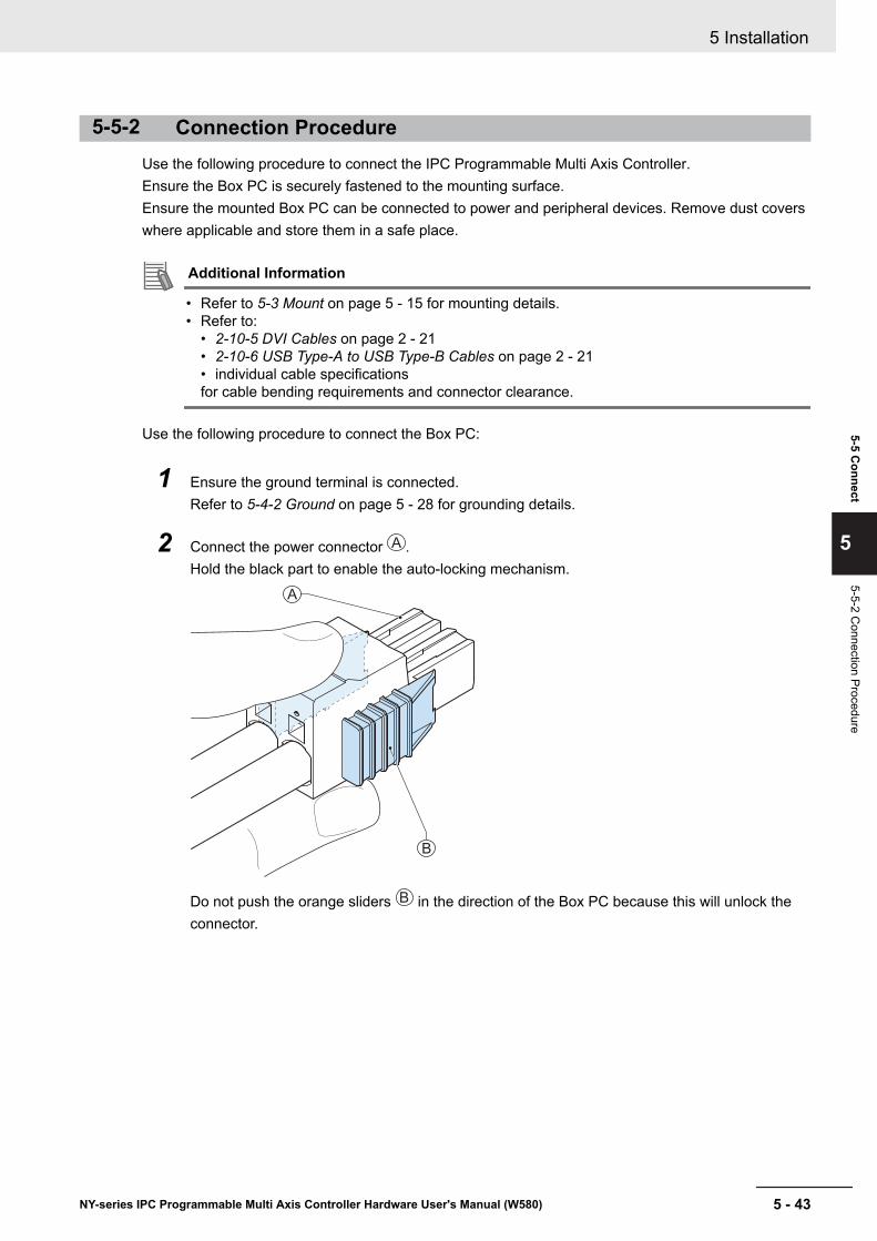
5-5-2 Connection ProcedureUse the following procedure to connect the IPC Programmable Multi Axis Controller.Ensure the Box PC is securely fastened to the mounting surface.Ensure the mounted Box PC can be connected to power and peripheral devices. Remove dust coverswhere applicable and store them in a safe place.
Additional Information
• Refer to 5-3 Mount on page 5 - 15 for mounting details.• Refer to:
• 2-10-5 DVI Cables on page 2 - 21• 2-10-6 USB Type-A to USB Type-B Cables on page 2 - 21• individual cable specificationsfor cable bending requirements and connector clearance.
Use the following procedure to connect the Box PC:
1 Ensure the ground terminal is connected.Refer to 5-4-2 Ground on page 5 - 28 for grounding details.
2 Connect the power connector A .Hold the black part to enable the auto-locking mechanism.
B
A
Do not push the orange sliders B in the direction of the Box PC because this will unlock theconnector.
5 Installation
5 - 43NY-series IPC Programmable Multi Axis Controller Hardware User's Manual (W580)
5-5 Connect
5
5-5-2 Connection Procedure

3 Connect the I/O connector.
Hold the black part A when inserting the connector, this enables the auto-locking mechanism.
B
A
Do not tilt the orange levers B because this will unlock the connector.
4 Connect an external monitor such as the Industrial Monitor.Connect the monitor to the DVI connector and tighten the fastening screws or use the optionalNYML connector.For an Industrial Panel PC this is optional because a monitor is integrated.
5 Connect a device to the optional interface (DVI, RS-232C or NYML) if applicable and tightenthe fastening screws when applicable.
6 Connect the USB ports to peripheral devices .
7 Connect the Box PC to the required Ethernet interface connector(s).Refer to 5-5-3 Ethernet Connection Procedure on page 5 - 44 for Ethernet port details.
The Box PC is connected.
5-5-3 Ethernet Connection ProcedureUse the following procedure to connect the Ethernet connectors of the IPC Programmable Multi AxisController.
1 Remove the dust caps from the Ethernet ports to be connected.
2 Connect Ethernet Port 1 of the Box PC to the EtherCAT network.
3 Connect Ethernet port 2 of the Box PC to the Modbus-TCP network.
4 Connect Ethernet port 3 of the Box PC to a normal Ethernet network.The Ethernet connectors are connected.
5 Installation
5 - 44 NY-series IPC Programmable Multi Axis Controller Hardware User's Manual (W580)
5-6 Initial Power ONThis section describes how to Power ON the IPC Programmable Multi Axis Controller for the first time.
WARNINGEnsure that installation and post-installation checks of the product areperformed by personnel in charge who possess a thorough understand-ing of the machinery to be installed.
5-6-1 Initial Power ON ProcedureUse the following procedure to power ON the IPC Programmable Multi Axis Controller for the first time.
1 Ensure the following conditions are present before applying power for the first time:• The Box PC is securely fastened to the mounting surface.• The Box PC is connected to ground.• All connectors are securely fastened.
2 Ensure that the connected monitor(s) is powered ON.
3 Connect a keyboard and/or a mouse.
Additional Information
• If using an OMRON Industrial Monitor this may not be required because it has touch function-ality.
• Do not connect additional storage devices before the installation of the operating systemcompleted. Adding storage devices like a USB flash drive, an SD memory card or a PCIecard might influence the default drive letter sequence.
4 Ensure the power supply is ON.
Precautions for Safe Use
Always check the power supply and power connections before applying power.Incorrect power connections can damage the product or cause burning.
5 Press the power button and release within 1 second.Refer to 2-4 Power Button on page 2 - 9 for the power button location.The Box PC starts and the PWR LED will go ON.
Additional Information
• Do not connect or disconnect the DVI-D cable while power is supplied to the Box PC.• If a Windows operating system is preinstalled:
• the Windows configuration will automatically start• refer to Windows Startup First Time for details
6 Verify the ERR LED is OFF.
5 Installation
5 - 45NY-series IPC Programmable Multi Axis Controller Hardware User's Manual (W580)
5-6 Initial Power O
N
5
5-6-1 Initial Power O
N Procedure
The Box PC is ON and if an operating system is installed it will start.
Precautions for Safe Use
Always use the SMART monitoring feature for storage devices that do not comply to the OmronStorage Device Specifications. Monitor the operating temperature and vibrations to ensure theystay within the environmental specifications of the storage device.
Additional Information
• The first time initialization will prepare the system and automatically reboot the Box PC whenrequired.
• Install support software to fully utilize your Box PC and optional connected hardware like theIndustrial Monitor.
5 Installation
5 - 46 NY-series IPC Programmable Multi Axis Controller Hardware User's Manual (W580)
5-6-2 Windows Startup First TimeUse the following procedure for the first time startup of Windows on your Box PC.
Additional Information
Do not power OFF the Box PC during this procedure!At the end of this procedure an automatic restart will result in the Windows home screen.
1 Ensure an input device is present.• For an Industrial Box PC connect a keyboard and mouse or a touch monitor.• For an Industrial Panel PC touch functionality is available. A keyboard and mouse are not
required.
2 Follow the windows installation procedure.
Pay special attention to the following steps:• Language
Select the preferred language in the Language Selection WindowSelect the language carefully, the selected system language can not be changed.Refer to 4-3-2 Supported Languages on page 4 - 20 for supported languages.
• Legal stuff like license agreements• Windows 10: Select Accept to accept the combined Windows and OMRON license agree-
ments.• Windows 7: Select Accept separately for Windows and for the OMRON utilities.
• Settings• Windows 10: Select Customize instead of Use Express settings.
Set the settings according to your application environment.• Windows 7: Select Use recommended settings.
• Create a user account and password and enter the password hint
WARNINGSecurity setting adjustments should only be performed by the engineerin charge that possesses a thorough understanding of the security set-tings. Selecting non-recommended security settings can put your sys-tem at risk.
Precautions for Safe Use
• Choose an OS password that is not obvious to prevent unauthorized access.• Remember the OS user name and password. The product is inaccessible without it.
The Box PC will automatically restart.A black screen will be visible for a few seconds and then the Box PC will boot to the Windowsstart screen.
3 Login
4 Adjust the backlight, Logo LED, and Status LED brightness of the monitor(s) to your settings.
5 Installation
5 - 47NY-series IPC Programmable Multi Axis Controller Hardware User's Manual (W580)
5-6 Initial Power O
N
5
5-6-2 Window
s Startup First Time

Additional Information
• Use the Industrial Monitor Utility to adjust the display and/or connected OMRON IndustrialMonitor.
• Verify that the Box PC is responding to finger touches on the touchscreen of the product.
5 Install any third party software and drivers that may be required for your applications.
Precautions for Safe Use
Before operating the system, please make sure the appropriate software is installed and config-ured. Doing so may prevent unexpected operation.
5 Installation
5 - 48 NY-series IPC Programmable Multi Axis Controller Hardware User's Manual (W580)

5-7 Install SoftwareThis section describes how to install the software for the IPC Programmable Multi Axis Controller.
5-7-1 Internet BrowserDepending on the operating system an Internet Browser is preinstalled.• For Windows 10 the standard Internet Browser is installed.• For Windows 7 an executable file for browser installation is provided in the user data partition of the
drive. For Windows 7 use the procedure below to perform the browser installation.
Additional Information
• Check the IT policy of your company for available software and for details on the softwareenvironment the IPC Programmable Multi Axis Controller will operate in.
• Install all updates and ensure the browser stays up-to-date.
To install the available Internet Browser in a Windows 7 operating system:
1 Use Windows Explorer to examine the contents of the user data partition mapped as drive let-ter D:.
2 Open the Installer folder (D:\OMRON-NY\Installers) and locate the Internet Explorer installerfiles.
3 Select the installer suitable for your system (32/64 bits) and language (English/Japanese).
4 Ensure there is a connection to the Internet.
5 Launch the installer to begin the installation process.
6 Follow the installer steps to complete the browser installation.
7 Download and install the latest updates via Windows Update.The Internet Browser is installed in Windows 7.
5 Installation
5 - 49NY-series IPC Programmable Multi Axis Controller Hardware User's Manual (W580)
5-7 Install Software
5
5-7-1 Internet Browser
5-7-2 FirewallAn industrial network should be separated from an office network.Depending on the operating system a Firewall is preinstalled.• For Windows 10 the standard firewall software is installed and enabled.• For Windows 7 the Firewall software is not installed.
Precautions for Safe Use
• Separate the machine network segment from the office network to avoid communication fail-ures.
• Install all updates and ensure the firewall stays up-to-date.
Additional Information
Check the IT policy of your company for available software and for details on the software envi-ronment the IPC Programmable Multi Axis Controller will operate in.
5-7-3 Anti-virus SoftwareThe Windows operating system is vulnerable for viruses. Anti-virus software should be installed on theWindows operating system.Depending on the operating system Anti-virus software is preinstalled.• For Windows 10 the standard Anti-virus software is installed and enabled.• For Windows 7 Anti-virus software is not installed.
Additional Information
Check the IT policy of your company for available software and for details on the software envi-ronment the IPC Programmable Multi Axis Controller will operate in.
Precautions for Safe Use
• Make sure that your operating system environment is protected against malicious softwareand viruses.
• Install all updates and ensure virus definitions stay up-to-date.
5 Installation
5 - 50 NY-series IPC Programmable Multi Axis Controller Hardware User's Manual (W580)
5-7-4 Drivers and Custom SoftwareUse the following procedure to install drivers and custom software on your IPC Programmable MultiAxis Controller.• For an Industrial PC without Operating System download the drivers from the OMRON download
website.• For an Industrial PC with a Windows operating system the drivers for most OMRON devices and
common third party devices are already available on the product. They will be installed automaticallyafter the initial Windows configuration or upon connection of a device to the Box PC.
1 Install drivers that are required for the application.
2 Install third-party software that is required for application.Follow the installation instructions as supplied with the driver or software.
Precautions for Safe Use
Before operating the system, please make sure the appropriate software is installed and config-ured. Doing so may prevent unexpected operation.
5-7-5 Customize WindowsWindows provides customization tools.Using these tools is only allowed for experienced software engineers.
Additional Information
• Refer to A-2-1 Enhanced Write Filter on page A - 11 for EWF details.• Refer to A-2-2 File-Based Write Filter on page A - 12 for FBWF details.
5 Installation
5 - 51NY-series IPC Programmable Multi Axis Controller Hardware User's Manual (W580)
5-7 Install Software
5
5-7-4 Drivers and C
ustom Softw
are
5-8 Connect UPSThe OMRON S8BA UPS protects the Box PC from power failures, voltage variations and instantane-ous voltage drops. Short power interruptions will be backed up by the UPS and the Box PC will contin-ue normal operation. The UPS signals the Box PC when a power failure occurs and then the Box PCcan shutdown normally without data loss. The Box PC can automatically start up again when the pow-er is restored.To connect the Box PC to the OMRON S8BA UPS use one of the following two options:• The USB connector and Power Attendant Lite Utility Software.
Refer to 5-8-1 Connect UPS Using the USB Connector on page 5 - 53 for details.This is the preferred connection method.
• The I/O connector and a custom software programRefer to 5-8-2 Connect UPS Using the I/O Connector on page 5 - 56 for details.
WARNINGThe use of an uninterruptible power supply (UPS) allows normal opera-tion to continue even if a momentary power failure occurs, possibly re-sulting in the reception of an erroneous signal from an external deviceaffected by the momentary power failure. Take external fail-safe meas-ures. Where necessary, monitor the power supply voltage on the sys-tem for external devices and use it as an interlock condition.
Precautions for Safe Use
• Always use an uninterruptible power supply (UPS) to prevent data loss and other system fileintegrity issues caused by unexpected power interruption.
• Use an Omron S8BA UPS with the correct revision number to prevent improper system shut-down.
• Correctly perform wiring and setting, and ensure that the shutdown by the UPS can be exe-cuted.
Additional Information
• The minimum power requirements of the UPS are dependent on the power consumption.Refer to 4-1-3 Power Consumption Specifications on page 4 - 4 for power consumption de-tails.
• Refer to the OMRON website for S8BA specifications or to the UPS S8BA User's Manual(Cat. No. U702) for the UPS manual.Note that the power consumption details determine the output current/capacity of your UPS.
5 Installation
5 - 52 NY-series IPC Programmable Multi Axis Controller Hardware User's Manual (W580)

5-8-1 Connect UPS Using the USB ConnectorThe Power Attendant Lite Utility software monitors the UPS status via the USB interface and shutsdown the IPC Programmable Multi Axis Controller when needed.
UPS Drivers and the required software is available.• For Box PCs with Windows 10 or Windows 7 preinstalled:
• Drivers for the S8BA UPS are pre-installed• Installation files and manual for the Power Attendant Lite Utility are available in the directory
D:\OMRON-NY\Installers\Power Attendant Lite Utility• Installation files and manual for the UPS Settings Utility are available in the directory
D:\OMRON-NY\Installers\UPS Settings Utility• For all other Box PCs following software can be downloaded from the OMRON download site:
• Drivers for the S8BA UPS• Installation files and manual for the Power Attendant Lite Utility• Installation files and manual for the UPS Settings Utility (Windows only)
Precautions for Safe Use
• Always use an uninterruptible power supply (UPS) to prevent data loss and other system fileintegrity issues caused by unexpected power interruption.
• Use an Omron S8BA UPS with the correct revision number to prevent improper system shut-down.
• Correctly perform wiring and setting, and ensure that the shutdown by the UPS can be exe-cuted.
Follow the steps below to connect the S8BA UPS with a USB cable and to configure it correctly.Refer to 2-10-9 UPS on page 2 - 23 for more information.
1 Ensure the revision number of the UPS is correct.Refer to 2-10-9 UPS on page 2 - 23 for more information.
2 For Box PCs that do not have Windows pre-installed: Download the above mentioned soft-ware.
3 Wire the S8BA UPS.
(1) Wire the input of the UPS to the output of the Power Supply.
(2) Wire the output of the UPS to the power connector of the Box PC.
(3) Ground the UPS.
(4) Connect the USB port of the S8BA UPS to the USB port of the Box PC using the USBcable provided with the S8BA UPS.
5 Installation
5 - 53NY-series IPC Programmable Multi Axis Controller Hardware User's Manual (W580)
5-8 Connect U
PS
5
5-8-1 Connect U
PS Using the U
SB Connector
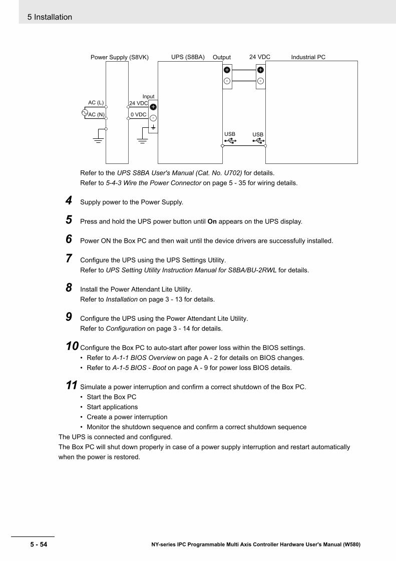
USB USB
Industrial PC
Input
24 VDCPower Supply (S8VK)
AC (L)
AC (N)
24 VDC
0 VDC
UPS (S8BA) Output
Refer to the UPS S8BA User's Manual (Cat. No. U702) for details.Refer to 5-4-3 Wire the Power Connector on page 5 - 35 for wiring details.
4 Supply power to the Power Supply.
5 Press and hold the UPS power button until On appears on the UPS display.
6 Power ON the Box PC and then wait until the device drivers are successfully installed.
7 Configure the UPS using the UPS Settings Utility.Refer to UPS Setting Utility Instruction Manual for S8BA/BU-2RWL for details.
8 Install the Power Attendant Lite Utility.Refer to Installation on page 3 - 13 for details.
9 Configure the UPS using the Power Attendant Lite Utility.Refer to Configuration on page 3 - 14 for details.
10 Configure the Box PC to auto-start after power loss within the BIOS settings.• Refer to A-1-1 BIOS Overview on page A - 2 for details on BIOS changes.• Refer to A-1-5 BIOS - Boot on page A - 9 for power loss BIOS details.
11 Simulate a power interruption and confirm a correct shutdown of the Box PC.• Start the Box PC• Start applications• Create a power interruption• Monitor the shutdown sequence and confirm a correct shutdown sequence
The UPS is connected and configured.The Box PC will shut down properly in case of a power supply interruption and restart automaticallywhen the power is restored.
5 Installation
5 - 54 NY-series IPC Programmable Multi Axis Controller Hardware User's Manual (W580)

Additional Information
• The default Input sensitivity setting is Standard voltage sensitivity and this is correct.Do not set this parameter to Low voltage sensitivity. Doing so can cause a system malfunc-tion when switching to battery mode.
• The UPS Setting Utility can not be used when the Power Attendant Lite Utility is active.To use the UPS Setting Utility:(1) Right-click the Power Attendant Lite Utility icon and select Agent Stop.(2) Use the UPS Setting Utility.(3) Right-click the Power Attendant Lite Utility icon and select Agent Start.
5 Installation
5 - 55NY-series IPC Programmable Multi Axis Controller Hardware User's Manual (W580)
5-8 Connect U
PS
5
5-8-1 Connect U
PS Using the U
SB Connector
5-8-2 Connect UPS Using the I/O ConnectorThe I/O connector of the IPC Programmable Multi Axis Controller:• receives the power status of the UPS with the UPS Mode Input when the Box PC has a Windows
operating system. For other operating systems this input is not functional.• indicates the power status of the Box PC to the UPS with the Power Status Output.
Additional Information
• A UPS connection using the I/O connector is only possible for a Box PC with a Windows op-erating system. For all other operating systems use the USB connector to connect the UPS.Refer to 5-8-1 Connect UPS Using the USB Connector on page 5 - 53 for details.
• The Box PC does not react automatically to the UPS Mode Input.A custom software program is required to shut down the Box PC when needed.
UPS Drivers and the required software is available.• For Box PCs with Windows 10 or Windows 7 preinstalled:
• Drivers for the S8BA UPS are pre-installed• Installation files and manual for the UPS Settings Utility are availabe in the installer directory
D:\OMRON-NY\Installers\UPS Settings Utility• For all other Box PCs following software can be downloaded from the OMRON download site:
• Drivers for the S8BA UPS• Installation files and manual for the UPS Settings Utility (Windows only)
Precautions for Safe Use
• Always use the recommended uninterruptible power supply (UPS) to prevent data loss andother system file integrity issues caused by unexpected power interruption.
• Use an Omron S8BA UPS with the correct revision number to prevent improper system shut-down.
• Correctly perform wiring and setting, and ensure that the shutdown by the UPS can be exe-cuted.
Follow the steps below to connect the S8BA UPS to the I/O connector of the Box PC and to configureit correctly.Refer to 5-4-4 Wire the I/O Connector on page 5 - 38 for I/O Connector details.
1 Ensure the revision number of the UPS is correct.Refer to 2-10-9 UPS on page 2 - 23 for more information.
2 For Box PCs that do not have Windows pre-installed: Download the above mentioned soft-ware.
3 Wire the S8BA UPS.
(1) Wire the input of the UPS to the output of the Power Supply.
(2) Wire the output of the UPS to the power connector of the Box PC.
(3) Ground the UPS.
(4) Connect the Contact port of the S8BA UPS to the I/O port of the Box PC with the connec-tion cable S8BW-02.
5 Installation
5 - 56 NY-series IPC Programmable Multi Axis Controller Hardware User's Manual (W580)
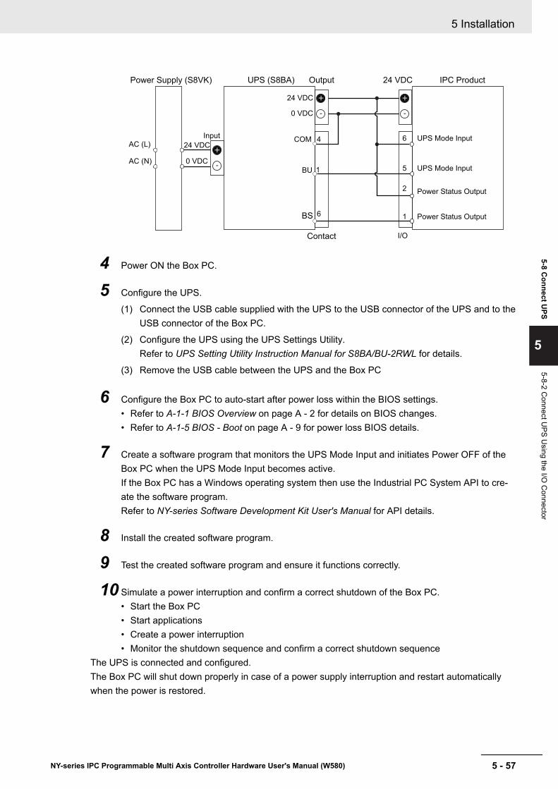
IPC Product
Input
24 VDCPower Supply (S8VK)
AC (L)
AC (N)
24 VDC
0 VDC
UPS (S8BA)
BU
BS
COM
Contact I/O
6
5
2
1
24 VDC
0 VDC
Output
4 6
1
UPS Mode Input
UPS Mode Input
Power Status Output
Power Status Output
4 Power ON the Box PC.
5 Configure the UPS.
(1) Connect the USB cable supplied with the UPS to the USB connector of the UPS and to theUSB connector of the Box PC.
(2) Configure the UPS using the UPS Settings Utility.Refer to UPS Setting Utility Instruction Manual for S8BA/BU-2RWL for details.
(3) Remove the USB cable between the UPS and the Box PC
6 Configure the Box PC to auto-start after power loss within the BIOS settings.• Refer to A-1-1 BIOS Overview on page A - 2 for details on BIOS changes.• Refer to A-1-5 BIOS - Boot on page A - 9 for power loss BIOS details.
7 Create a software program that monitors the UPS Mode Input and initiates Power OFF of theBox PC when the UPS Mode Input becomes active.If the Box PC has a Windows operating system then use the Industrial PC System API to cre-ate the software program.Refer to NY-series Software Development Kit User's Manual for API details.
8 Install the created software program.
9 Test the created software program and ensure it functions correctly.
10 Simulate a power interruption and confirm a correct shutdown of the Box PC.• Start the Box PC• Start applications• Create a power interruption• Monitor the shutdown sequence and confirm a correct shutdown sequence
The UPS is connected and configured.The Box PC will shut down properly in case of a power supply interruption and restart automaticallywhen the power is restored.
5 Installation
5 - 57NY-series IPC Programmable Multi Axis Controller Hardware User's Manual (W580)
5-8 Connect U
PS
5
5-8-2 Connect U
PS Using the I/O
Connector

Additional Information
The default Input sensitivity setting is Standard voltage sensitivity and this is correct.Do not set this parameter to Low voltage sensitivity. Doing so can cause a system malfunc-tion when switching to battery mode.
5 Installation
5 - 58 NY-series IPC Programmable Multi Axis Controller Hardware User's Manual (W580)

5-9 Create a Windows System RepairDisk and a Windows Backup
A Windows Repair Disk is a disk that enables users to restore the Windows operating system.A Windows Backup is a backup that enables users to restore a user-defined content set.Use the following procedures to ensure you can always go back to this situation.
1 Create a Windows System Repair Disk.Refer to 5-9-2 Create a Windows System Repair Disk on page 5 - 59 for details.
2 Create a Windows Backup.Refer to 7-1-4 Create a Custom Backup with Windows Backup on page 7 - 5 for details.
5-9-1 Industrial PC with Programmable Multi Axis Controller Backup
Additional Information
The Programmable Multi Axis Controller is not included in the Windows System Repair Diskand not included in the Windows Backup.
5-9-2 Create a Windows System Repair DiskA Windows System Repair Disk can repair Windows if a serious error occurs.
Additional Information
To create a Windows System Repair Disk, a separate Windows PC with a DVD writer is re-quired that has the same Windows edition and System type as the IPC Programmable Multi Ax-is Controller. The Windows System Repair Disk can not be created with the IPC ProgrammableMulti Axis Controller.
Prepare:• A PC with a DVD writer that has the same Windows edition and System type as your Box PC.
• An example of the Windows edition is "Windows 7" with "Service Pack 1".• An example of the System type is "64-bit Operating System".
• An empty DVDUse the Windows Backup and Restore mechanisms on the PC with a DVD writer to create a systemrepair disk.
To create a Windows System Repair Disk:
1 Start the PC that has a DVD writer and login.
2 Select the Windows Start Button.
3 In the search field, input Backup.
5 Installation
5 - 59NY-series IPC Programmable Multi Axis Controller Hardware User's Manual (W580)
5-9 Create a W
indows System
Repair D
isk and a Window
s Backup
5
5-9-1 Industrial PC w
ith Programm
able Multi Axis C
ontroller Backup
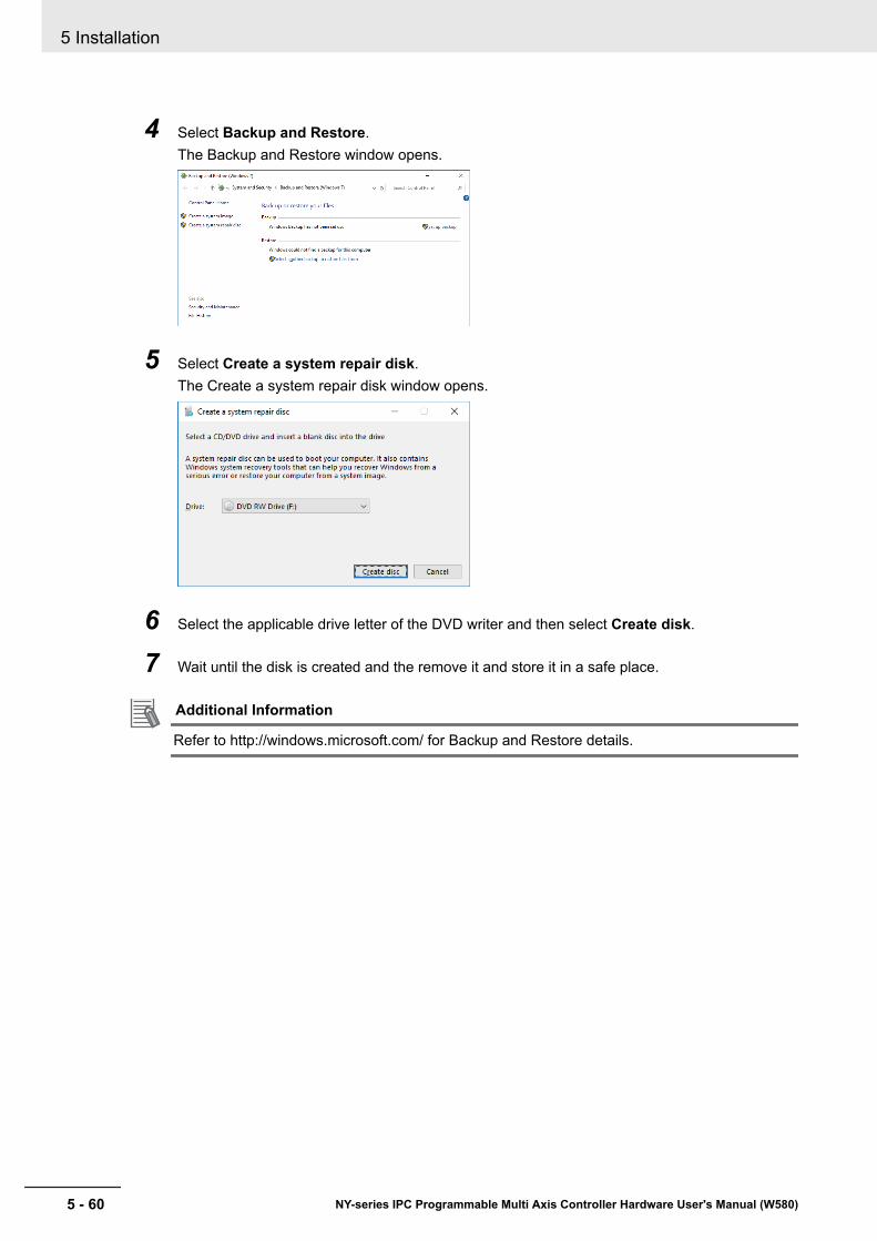
4 Select Backup and Restore.The Backup and Restore window opens.
5 Select Create a system repair disk.The Create a system repair disk window opens.
6 Select the applicable drive letter of the DVD writer and then select Create disk.
7 Wait until the disk is created and the remove it and store it in a safe place.
Additional Information
Refer to http://windows.microsoft.com/ for Backup and Restore details.
5 Installation
5 - 60 NY-series IPC Programmable Multi Axis Controller Hardware User's Manual (W580)
6Operating Procedures
This section provides the operating procedures for the IPC Programmable Multi AxisController.
6-1 Power ON ...................................................................................................... 6 - 26-1-1 Power ON Using the Power Button .............................................................. 6 - 26-1-2 Power ON Using the Power ON/OFF Input .................................................. 6 - 26-1-3 Auto Power ON............................................................................................. 6 - 2
6-2 Power OFF .................................................................................................... 6 - 36-2-1 Power OFF Using the Power PMAC Support Utility ..................................... 6 - 36-2-2 Forced Power OFF Using the Power Button ................................................ 6 - 3
6-3 React to Product Messages ........................................................................ 6 - 56-4 React to Windows Messages ...................................................................... 6 - 6
6 - 1NY-series IPC Programmable Multi Axis Controller Hardware User's Manual (W580)
6
6-1 Power ONThis section provides Power ON details.
6-1-1 Power ON Using the Power ButtonStart condition: Power is supplied to the Box PC and the Box PC is OFF.
1 Press the power button and release within 1 second.Refer to 2-4 Power Button on page 2 - 9 for the power button location.The Box PC starts and the PWR LED will turn ON.
2 Wait until the PWR LED is ON and verify that the ERR LED is OFF.The Box PC is ON and the Operating System, if installed, starts.
6-1-2 Power ON Using the Power ON/OFF InputStart condition: Power is supplied to the Box PC and the Box PC is OFF.
1 Supply an input signal to pins 3 and 4 of the I/O connector.The input signal must remain ON for a minimum of 60 ms and a maximum of 750 ms to becorrectly detected by the Box PC.The Box PC starts and the PWR LED will turn ON.
2 Wait until the PWR LED is ON and verify that the ERR LED is OFF.The Box PC is ON and the Operating System, if installed, starts.
Additional Information
• Refer to 4-2-2 I/O Connector Specifications on page 4 - 10 for connector specifications.• Refer to 5-4-4 Wire the I/O Connector on page 5 - 38 for wiring details.
6-1-3 Auto Power ONThe Box PC can be configured to start up when power is supplied to the power connector.The Power Loss Control BIOS setting controls this behavior.Set the Power Loss Control setting to Turn ON to activate the Auto Power ON function.
Additional Information
Refer to A-1-5 BIOS - Boot on page A - 9 for BIOS details.
6 Operating Procedures
6 - 2 NY-series IPC Programmable Multi Axis Controller Hardware User's Manual (W580)
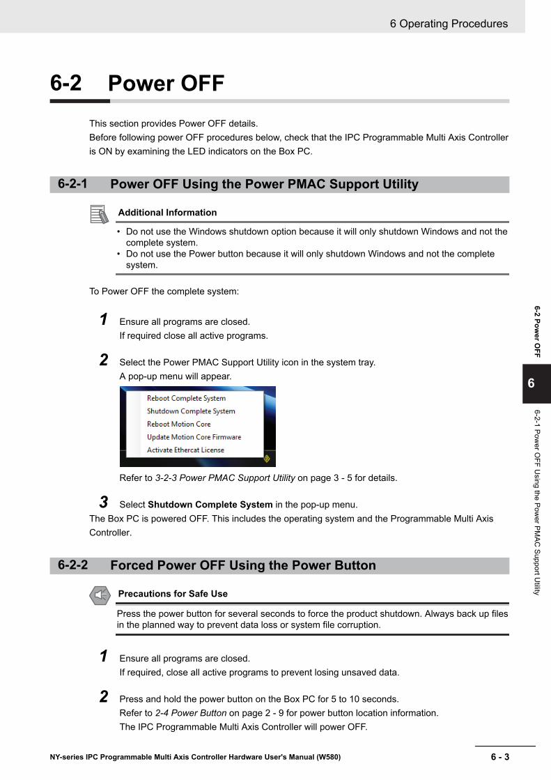
6-2 Power OFFThis section provides Power OFF details.Before following power OFF procedures below, check that the IPC Programmable Multi Axis Controlleris ON by examining the LED indicators on the Box PC.
6-2-1 Power OFF Using the Power PMAC Support Utility
Additional Information
• Do not use the Windows shutdown option because it will only shutdown Windows and not thecomplete system.
• Do not use the Power button because it will only shutdown Windows and not the completesystem.
To Power OFF the complete system:
1 Ensure all programs are closed.If required close all active programs.
2 Select the Power PMAC Support Utility icon in the system tray.A pop-up menu will appear.
Refer to 3-2-3 Power PMAC Support Utility on page 3 - 5 for details.
3 Select Shutdown Complete System in the pop-up menu.The Box PC is powered OFF. This includes the operating system and the Programmable Multi AxisController.
6-2-2 Forced Power OFF Using the Power Button
Precautions for Safe Use
Press the power button for several seconds to force the product shutdown. Always back up filesin the planned way to prevent data loss or system file corruption.
1 Ensure all programs are closed.If required, close all active programs to prevent losing unsaved data.
2 Press and hold the power button on the Box PC for 5 to 10 seconds.Refer to 2-4 Power Button on page 2 - 9 for power button location information.The IPC Programmable Multi Axis Controller will power OFF.
6 Operating Procedures
6 - 3NY-series IPC Programmable Multi Axis Controller Hardware User's Manual (W580)
6-2 Power O
FF
6
6-2-1 Power O
FF Using the Pow
er PMAC
Support Utility

Any optional operating system settings related to power OFF will be disregarded.
3 Wait until the PWR LED is OFF.The Box PC is powered OFF.Confirm normal operation and check all product settings because unsaved data was lost.
6 Operating Procedures
6 - 4 NY-series IPC Programmable Multi Axis Controller Hardware User's Manual (W580)
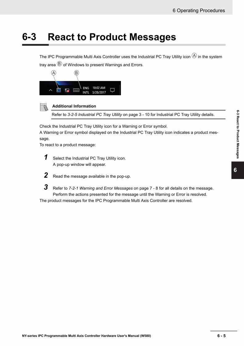
6-3 React to Product Messages
The IPC Programmable Multi Axis Controller uses the Industrial PC Tray Utility icon A in the system
tray area B of Windows to present Warnings and Errors.
A B
Additional Information
Refer to 3-2-5 Industrial PC Tray Utility on page 3 - 10 for Industrial PC Tray Utility details.
Check the Industrial PC Tray Utility icon for a Warning or Error symbol.A Warning or Error symbol displayed on the Industrial PC Tray Utility icon indicates a product mes-sage.To react to a product message:
1 Select the Industrial PC Tray Utility icon.A pop-up window will appear.
2 Read the message available in the pop-up.
3 Refer to 7-2-1 Warning and Error Messages on page 7 - 8 for all details on the message.Perform the actions presented for the message until the Warning or Error is resolved.
The product messages for the IPC Programmable Multi Axis Controller are resolved.
6 Operating Procedures
6 - 5NY-series IPC Programmable Multi Axis Controller Hardware User's Manual (W580)
6-3 React to Product M
essages
6

6-4 React to Windows Messages
Windows uses the Windows Action Center icon A in the system tray area B of Windows to presentWarnings and Errors.
AB A B
Windows 10 Windows 7
Check the Windows Action Center icon for a Warning or Error symbol.A Warning or Error symbol displayed on the Windows Action Center icon indicates a Windows mes-sage.To react to a Windows message:
1 Open the Windows Action Center.• For Windows 10: Click the Windows Action Center icon.• For Windows 7: Rightclick the Windows Action Center icon and select Open Action Center
from the pop-up window.A pop-up window will appear.
Windows 10 Windows 7
2 Read the message available in the window.
3 Perform the actions until each Warning or Error is resolved.The Windows messages for the IPC Programmable Multi Axis Controller are resolved.
6 Operating Procedures
6 - 6 NY-series IPC Programmable Multi Axis Controller Hardware User's Manual (W580)
7Maintenance
This section provides an overview of all maintenance tasks for the IPC ProgrammableMulti Axis Controller.
7-1 Preventive Maintenance .............................................................................. 7 - 27-1-1 Preventive Maintenance Schedule ............................................................... 7 - 27-1-2 Clean the Box PC ......................................................................................... 7 - 47-1-3 Keep Software Updated................................................................................ 7 - 47-1-4 Create a Custom Backup with Windows Backup.......................................... 7 - 5
7-2 Corrective Maintenance............................................................................... 7 - 87-2-1 Warning and Error Messages ....................................................................... 7 - 87-2-2 Remove the Cover...................................................................................... 7 - 107-2-3 Replace the Fan Unit ...................................................................................7 - 117-2-4 Replace the Battery .................................................................................... 7 - 137-2-5 Replace a Drive .......................................................................................... 7 - 157-2-6 Replace the PCIe Card............................................................................... 7 - 207-2-7 Restore and Repair Data ............................................................................ 7 - 247-2-8 Allocate a Drive in Windows ....................................................................... 7 - 297-2-9 Windows Event Viewer ............................................................................... 7 - 30
7 - 1NY-series IPC Programmable Multi Axis Controller Hardware User's Manual (W580)
7

7-1 Preventive MaintenancePreventive Maintenance covers all actions that prevent downtime.
7-1-1 Preventive Maintenance SchedulePrevent unscheduled downtime with the following preventive maintenance schedule.
Daily ReferenceCheck IPC Programmable Multi Ax-is Controller status
• Refer to 7-2-1 Warning and Error Messages on page 7 - 8 for BoxPC Messages.
• Refer to 6-4 React to Windows Messages on page 6 - 6 for WindowsMessages.
• Refer to 2-3 LED Indicators on page 2 - 7 for LED details.Monitor storage devices that do notcomply to the Omron specifications
Refer to Storage Device Considerations on page 2 - 20 for details.
Weekly ReferenceClean the Box PC Refer to 7-1-2 Clean the Box PC on page 7 - 4 for cleaning details.Ensure you have the latest soft-ware updates
Refer to 7-1-3 Keep Software Updated on page 7 - 4 for update details.
When changing applications orconfigurations Reference
Create a backup of the IPC Pro-grammable Multi Axis Controller
Refer to 7-1-4 Create a Custom Backup with Windows Backup on page7 - 5 for backup details.
Periodically but at least every 6months Reference
Check the ambient environment:• Temperature and humidity within
specifications• Noise sources not close to the
IPC Programmable Multi AxisController
Refer to 4-4 Environmental Specifications on page 4 - 21 for environmen-tal specifications.
Check installation:IPC Programmable Multi Axis Con-troller mounted securely
Refer to 5-3 Mount on page 5 - 15 for installation details.
Check wiring and connections:• Cable connectors fully inserted
and locked• No damaged wiring or connec-
tors
Refer to 5-4 Wire on page 5 - 27 for wiring details.Refer to 5-5 Connect on page 5 - 41 for connection details.
Check the battery replacement dateon the label at the inside of theCover.Replace the battery before the re-placement date.
• Refer to 7-2-2 Remove the Cover on page 7 - 10 to check the label.• Refer to 7-2-4 Replace the Battery on page 7 - 13 to replace the bat-
tery.
Check that the Backup is availableand operational.
Refer to Restore a Custom Backup with Windows on page 7 - 25 for Re-store Backup details.
7 Maintenance
7 - 2 NY-series IPC Programmable Multi Axis Controller Hardware User's Manual (W580)
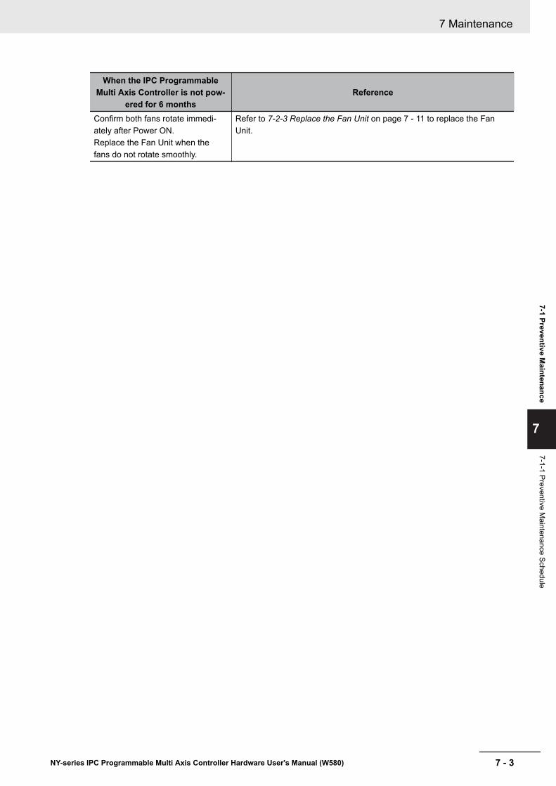
When the IPC ProgrammableMulti Axis Controller is not pow-
ered for 6 monthsReference
Confirm both fans rotate immedi-ately after Power ON.Replace the Fan Unit when thefans do not rotate smoothly.
Refer to 7-2-3 Replace the Fan Unit on page 7 - 11 to replace the FanUnit.
7 Maintenance
7 - 3NY-series IPC Programmable Multi Axis Controller Hardware User's Manual (W580)
7-1 Preventive Maintenance
7
7-1-1 Preventive Maintenance Schedule
7-1-2 Clean the Box PCClean the Box PC periodically in order to keep it in the best operating condition.Wipe the Box PC with a dry, soft cloth.
Precautions for Safe Use
Do not use corrosive substances to clean the product.Doing so may result in the failure or malfunction.
7-1-3 Keep Software UpdatedAlways keep software at the latest released version to ensure stable operation.This is specifically important for:• Anti-virus software• Firewall software• Internet browser• Windows security patches• OMRON software
Precautions for Correct Use
After an OS update or a peripheral device driver update for the product is executed, the productbehavior might be different. Confirm that operation is correct before you start actual operation.
Additional Information
• Refer to 5-7-1 Internet Browser on page 5 - 49 for Browser details.• Refer to 5-7-2 Firewall on page 5 - 50 for Firewall details.• Refer to 5-7-3 Anti-virus Software on page 5 - 50 for Anti-virus details.
7 Maintenance
7 - 4 NY-series IPC Programmable Multi Axis Controller Hardware User's Manual (W580)
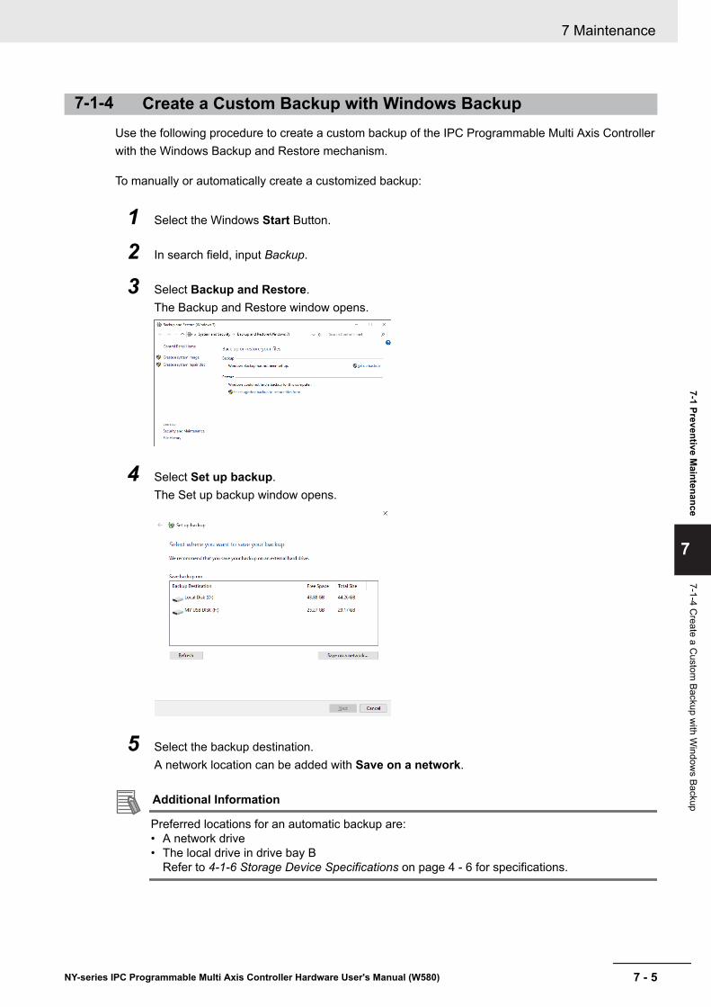
7-1-4 Create a Custom Backup with Windows BackupUse the following procedure to create a custom backup of the IPC Programmable Multi Axis Controllerwith the Windows Backup and Restore mechanism.
To manually or automatically create a customized backup:
1 Select the Windows Start Button.
2 In search field, input Backup.
3 Select Backup and Restore.The Backup and Restore window opens.
4 Select Set up backup.The Set up backup window opens.
5 Select the backup destination.A network location can be added with Save on a network.
Additional Information
Preferred locations for an automatic backup are:• A network drive• The local drive in drive bay B
Refer to 4-1-6 Storage Device Specifications on page 4 - 6 for specifications.
7 Maintenance
7 - 5NY-series IPC Programmable Multi Axis Controller Hardware User's Manual (W580)
7-1 Preventive Maintenance
7
7-1-4 Create a C
ustom Backup w
ith Window
s Backup
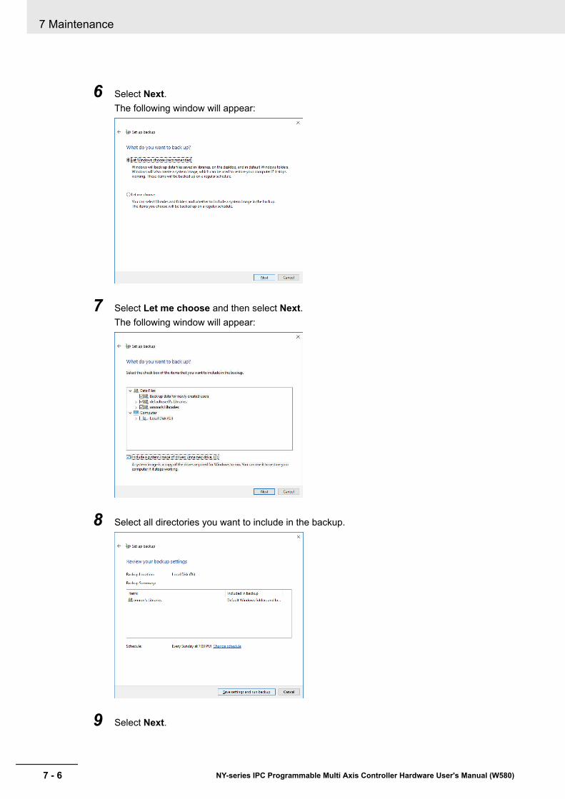
6 Select Next.The following window will appear:
7 Select Let me choose and then select Next.The following window will appear:
8 Select all directories you want to include in the backup.
9 Select Next.
7 Maintenance
7 - 6 NY-series IPC Programmable Multi Axis Controller Hardware User's Manual (W580)

10 Select Configure schedule or Change schedule and change the backup schedule.Ensure:• The interval is short enough to minimize data loss when a restore is required• The IPC Programmable Multi Axis Controller is powered ON during the backup periods• The time the backup is scheduled does not interfere with normal operationor uncheck Run backup on a schedule if an automatic backup is not possible.
11 Select OK.
12 Select Save settings and run backup to create the first backup.
Precautions for Correct Use
Create backups according to the preventive maintenance schedule to prevent data loss andsystem integrity issues.Refer to 7-1-1 Preventive Maintenance Schedule on page 7 - 2 for intervals.
Additional Information
• Check your backup to ensure it contains all data required for a restore.• Refer to http://windows.microsoft.com/ for Backup and Restore details.• Refer to Restore a Custom Backup with Windows on page 7 - 25 for the Restore Procedure.
7 Maintenance
7 - 7NY-series IPC Programmable Multi Axis Controller Hardware User's Manual (W580)
7-1 Preventive Maintenance
7
7-1-4 Create a C
ustom Backup w
ith Window
s Backup

7-2 Corrective MaintenanceCorrective maintenance covers all actions to correct problems that cause downtime.
WARNINGDo not attempt to disassemble, repair, or modify the product in anyway. Doing so may result in malfunction or fire.
Contact your local OMRON representative if the corrective maintenance actions did not solve theproblem.
7-2-1 Warning and Error MessagesWarning and Error messages are provided by the IPC Programmable Multi Axis Controller when thereis a potential problem that may cause downtime. This section provides details about these messages.Warning messages inform you about a situation that will lead to downtime of the IPC ProgrammableMulti Axis Controller.Error messages inform you about what caused the downtime of the IPC Programmable Multi AxisController.
The following message channels are available.
LED IndicatorsThe ERR LED indicator provides information on warnings and errors.
Additional Information
Refer to 2-3-2 ERR LED Indicator on page 2 - 8 for ERR details.
Industrial PC Support UtilityThe Industrial PC Support Utility provides information on warnings and errors.
The Industrial PC Support Utility indicates:• Internal temperature above setting
Check the status of the Fan Unit and check the ambient conditions.• Low revolution speed of the Fan Unit
• Check for excessive dust on the fans and in the Fan Unit.• If required replace the Fan Unit.
• Low battery statusReplace the battery.
7 Maintenance
7 - 8 NY-series IPC Programmable Multi Axis Controller Hardware User's Manual (W580)
Additional Information
• Refer to 4-4-1 Operation Environment Specifications on page 4 - 21 for environmental details.• Refer to 7-2-2 Remove the Cover on page 7 - 10 for fan details.• Refer to 7-2-3 Replace the Fan Unit on page 7 - 11 for Fan Unit replacement details.• Refer to 7-2-4 Replace the Battery on page 7 - 13 for battery replacement details.
Windows Action CenterThe Windows Action Center provides information on Windows related warnings and errors.
The Windows Action Center indicates security and maintenance issues.Some examples:• Virus protection (Important)
Windows did not find anti-virus software on this computer.• Windows Update (Important)
windows Update is not set up for this computer.• Set up backup
Your files are not being backed up.
Additional Information
Refer to 6-4 React to Windows Messages on page 6 - 6 for details.
7 Maintenance
7 - 9NY-series IPC Programmable Multi Axis Controller Hardware User's Manual (W580)
7-2 Corrective M
aintenance
7
7-2-1 Warning and Error M
essages

7-2-2 Remove the CoverThe Cover of the IPC Programmable Multi Axis Controller provides access to the following items.• Battery• Fan Unit (applies to products with active cooling)The inside of the Cover contains the following information.• Battery replacement date• License key for the operating system (optional)No tools are required to open the Cover.Use the following procedure to remove the Cover of the Box PC.
1 Power OFF your Box PC if it has active cooling.
Precautions for Safe Use
Do not remove the fan cover while the power is ON. Contact with the rotating fan may result ininjury.
2 Remove the Cover.
1
3
2
(1) Pull the lever 1 to unlock the Cover.
(2) Lift the side 2 to tilt the Cover.
(3) Remove 3 the complete Cover.
The Cover is removed.To mount the Cover, position the side of the Cover in the Box PC and push the cover in place.The lever will lock in place.
7 Maintenance
7 - 10 NY-series IPC Programmable Multi Axis Controller Hardware User's Manual (W580)
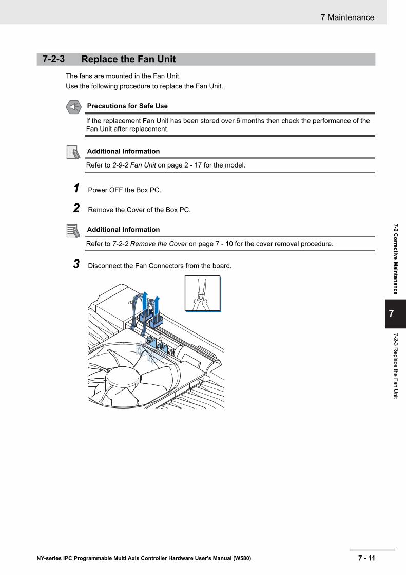
7-2-3 Replace the Fan UnitThe fans are mounted in the Fan Unit.Use the following procedure to replace the Fan Unit.
Precautions for Safe Use
If the replacement Fan Unit has been stored over 6 months then check the performance of theFan Unit after replacement.
Additional Information
Refer to 2-9-2 Fan Unit on page 2 - 17 for the model.
1 Power OFF the Box PC.
2 Remove the Cover of the Box PC.
Additional Information
Refer to 7-2-2 Remove the Cover on page 7 - 10 for the cover removal procedure.
3 Disconnect the Fan Connectors from the board.
7 Maintenance
7 - 11NY-series IPC Programmable Multi Axis Controller Hardware User's Manual (W580)
7-2 Corrective M
aintenance
7
7-2-3 Replace the Fan U
nit
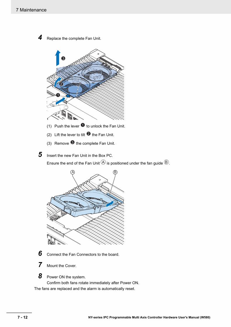
4 Replace the complete Fan Unit.
1
3
2
(1) Push the lever 1 to unlock the Fan Unit.
(2) Lift the lever to tilt 2 the Fan Unit.
(3) Remove 3 the complete Fan Unit.
5 Insert the new Fan Unit in the Box PC.
Ensure the end of the Fan Unit A is positioned under the fan guide B .
BA
6 Connect the Fan Connectors to the board.
7 Mount the Cover.
8 Power ON the system.Confirm both fans rotate immediately after Power ON.
The fans are replaced and the alarm is automatically reset.
7 Maintenance
7 - 12 NY-series IPC Programmable Multi Axis Controller Hardware User's Manual (W580)
7-2-4 Replace the Battery
Precautions for Safe Use
• The Battery may leak, rupture, heat, or ignite. Never short-circuit, charge, disassemble, heat,or incinerate the Battery or subject it to strong shock.
• Dispose of any Battery that has been dropped on the floor or otherwise subjected to exces-sive shock. Batteries that have been subjected to shock may leak if they are used.
• UL standards require that only an experienced engineer replace the Battery. Make sure thatan experienced engineer is in charge of Battery replacement.
Precautions for Correct Use
• Always touch a grounded piece of metal to discharge static electricity from your body beforestarting an installation or maintenance procedure.
• Make sure to use a battery of the correct type and install the battery properly.• Apply power for at least five minutes before changing the battery. Mount a new battery within
five minutes after turning OFF the power supply. If power is not supplied for at least five mi-nutes, the clock data may be lost. Check the clock data after changing the battery.
• Turn ON the power after replacing the battery for a product that has been unused for ax ex-tended period of time. Leaving the product unused without turning ON the power even onceafter the battery is replaced may result in a shorter battery life.
Additional Information
• Refer to 2-9-1 Battery on page 2 - 17 for the battery model.
Use the following procedure to replace the battery:
1 Power OFF the Box PC.
2 Remove the cover.
Additional Information
Refer to 7-2-2 Remove the Cover on page 7 - 10 for the cover removal procedure.
7 Maintenance
7 - 13NY-series IPC Programmable Multi Axis Controller Hardware User's Manual (W580)
7-2 Corrective M
aintenance
7
7-2-4 Replace the Battery

3 Lift the battery 1 from the compartment.
4 Disconnect the battery from the battery connector 2 .
2
1
5 Connect the new battery to the battery connector.
6 Place the new battery in the Box PC.Ensure the wires are at the side of the battery and not on top of the battery. If the wires are ontop of the battery this might make closing and opening the cover more difficult.
7 Write the next date of replacement on the label at the inside of the cover.
Additional Information
Refer to 2-9-1 Battery on page 2 - 17 for lifetime of the battery.
8 Mount the cover.
9 Remove the power connector for at least 3 seconds to reset the battery warning.
10 Power ON the Box PC.
11 Check the Date and Time in the operating system.Correct the Date and Time if this is required.
The battery is replaced and the alarm is reset.
7 Maintenance
7 - 14 NY-series IPC Programmable Multi Axis Controller Hardware User's Manual (W580)
7-2-5 Replace a DriveUse the following procedure to replace a drive.
Prepare the new drive.
Additional Information
• Refer to 1-5 Product Configuration on page 1 - 6 for the installed drive model.• Refer to 2-10-4 Storage Devices on page 2 - 20 for the available drive models.• Refer to 4-1-6 Storage Device Specifications on page 4 - 6 for drive specifications.
To replace a drive:
1 Power OFF the Box PC.
2 Remove the drive cover.
13
2
(1) Push the lock lever 1 .
(2) Tilt the cover 2 .
(3) Remove the drive cover 3 .
Additional Information
• Refer to 2-5 Drive Bays on page 2 - 10 for the location of the drive cover.• The Box PC has 2 drive bays, marked with "A" and "B" at the left side of the drive cover. Take
note of the bay position for the drive that is being removed and do not place a drive in theincorrect bay.
7 Maintenance
7 - 15NY-series IPC Programmable Multi Axis Controller Hardware User's Manual (W580)
7-2 Corrective M
aintenance
7
7-2-5 Replace a D
rive
3 Pull the metal shielding cover out of the Box PC.
4 Insert the drive cover in the drive bracket bay 1 and move it down 2 so that it locks in thedrive bracket.
2
1
7 Maintenance
7 - 16 NY-series IPC Programmable Multi Axis Controller Hardware User's Manual (W580)
5 Remove the drive bracket from the Box PC using the drive cover.
6 Remove the 4 mounting screws 1 and then remove the drive 2 from the drive bracket.
1
2
7 Maintenance
7 - 17NY-series IPC Programmable Multi Axis Controller Hardware User's Manual (W580)
7-2 Corrective M
aintenance
7
7-2-5 Replace a D
rive
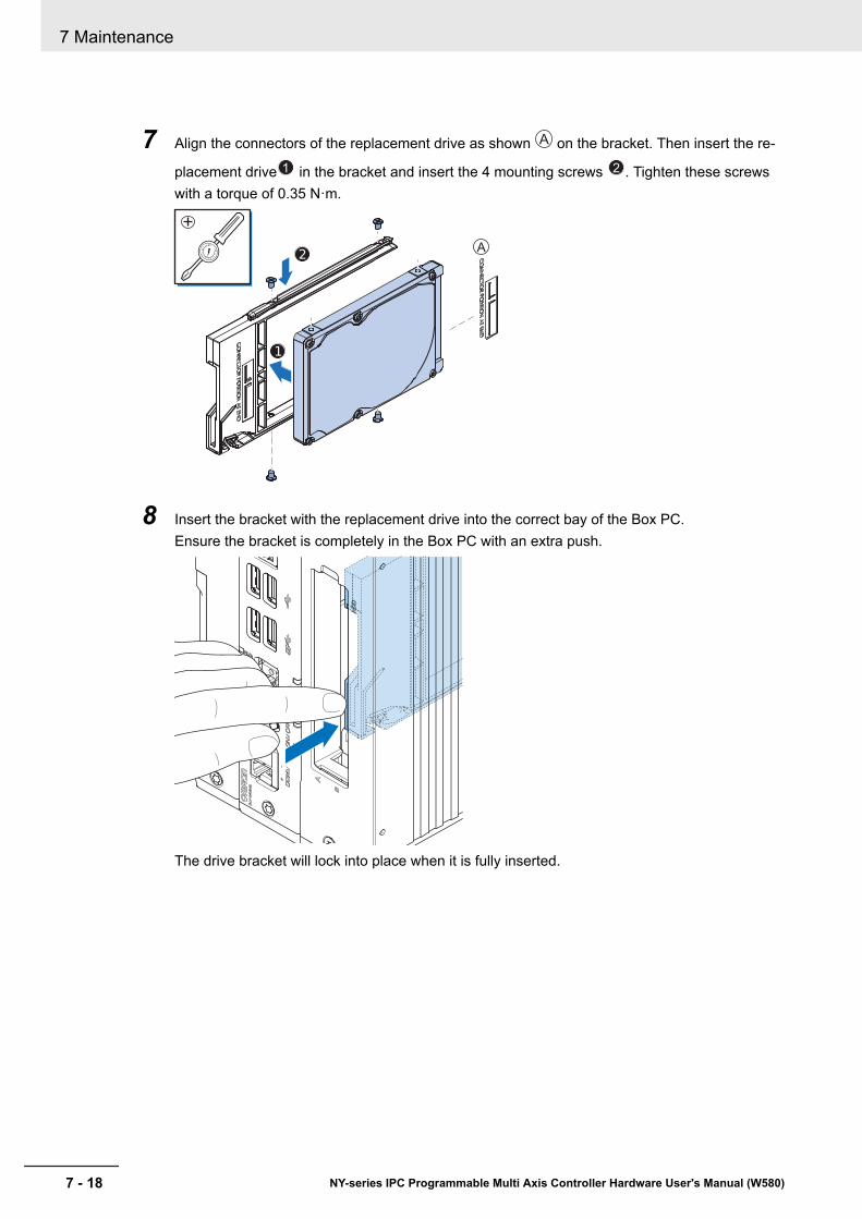
7 Align the connectors of the replacement drive as shown A on the bracket. Then insert the re-
placement drive 1 in the bracket and insert the 4 mounting screws 2 . Tighten these screwswith a torque of 0.35 N·m.
A0
15
8 Insert the bracket with the replacement drive into the correct bay of the Box PC.Ensure the bracket is completely in the Box PC with an extra push.
The drive bracket will lock into place when it is fully inserted.
7 Maintenance
7 - 18 NY-series IPC Programmable Multi Axis Controller Hardware User's Manual (W580)
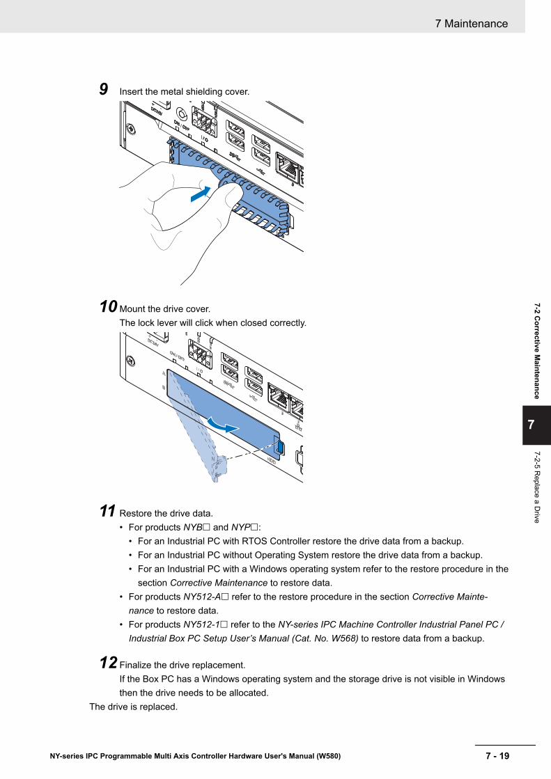
9 Insert the metal shielding cover.
10 Mount the drive cover.The lock lever will click when closed correctly.
11 Restore the drive data.• For products NYB£ and NYP£:
• For an Industrial PC with RTOS Controller restore the drive data from a backup.• For an Industrial PC without Operating System restore the drive data from a backup.• For an Industrial PC with a Windows operating system refer to the restore procedure in the
section Corrective Maintenance to restore data.• For products NY512-A£ refer to the restore procedure in the section Corrective Mainte-
nance to restore data.• For products NY512-1£ refer to the NY-series IPC Machine Controller Industrial Panel PC /
Industrial Box PC Setup User’s Manual (Cat. No. W568) to restore data from a backup.
12 Finalize the drive replacement.If the Box PC has a Windows operating system and the storage drive is not visible in Windowsthen the drive needs to be allocated.
The drive is replaced.
7 Maintenance
7 - 19NY-series IPC Programmable Multi Axis Controller Hardware User's Manual (W580)
7-2 Corrective M
aintenance
7
7-2-5 Replace a D
rive

7-2-6 Replace the PCIe CardUse the following procedure to replace the PCIe Card.
Prepare:• The PCIe Card
Additional Information
Refer to 4-1-7 PCIe Card Specifications on page 4 - 7 for PCIe specifications.
• The PCIe Card mounting materials: Card Clip and Card SupportThese are supplied with the IPC Programmable Multi Axis Controller.
To replace the PCIe Card:
1 Power OFF the system.
2 Unmount the Box PC.
3 Remove the two crosshead screws 1 indicated with "open" and then pull up 2 the PCIeDrawer.The indent at the side of the drawer will help you to pull the drawer from the Box PC.
2
1
1
7 Maintenance
7 - 20 NY-series IPC Programmable Multi Axis Controller Hardware User's Manual (W580)
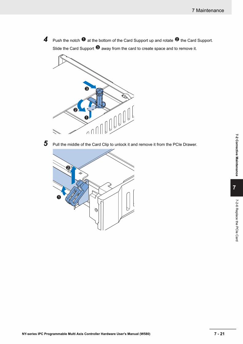
4 Push the notch 1 at the bottom of the Card Support up and rotate 2 the Card Support.
Slide the Card Support 3 away from the card to create space and to remove it.
2
1
3
5 Pull the middle of the Card Clip to unlock it and remove it from the PCIe Drawer.
2
1
7 Maintenance
7 - 21NY-series IPC Programmable Multi Axis Controller Hardware User's Manual (W580)
7-2 Corrective M
aintenance
7
7-2-6 Replace the PC
Ie Card

6 Remove the PCIe Card from the PCIe Drawer.
2
1
The PCIe Card is now removed.
7 Place the replacement PCIe Card in the PCIe Drawer.
1
2
Ensure the PCIe Card is inserted into the correct opening.
7 Maintenance
7 - 22 NY-series IPC Programmable Multi Axis Controller Hardware User's Manual (W580)
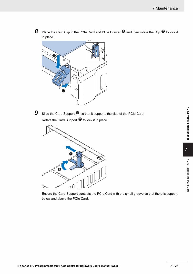
8 Place the Card Clip in the PCIe Card and PCIe Drawer 1 and then rotate the Clip 2 to lock itin place.
1
2
9 Slide the Card Support 1 so that it supports the side of the PCIe Card.
Rotate the Card Support 2 to lock it in place.
2
1
Ensure the Card Support contacts the PCIe Card with the small groove so that there is supportbelow and above the PCIe Card.
7 Maintenance
7 - 23NY-series IPC Programmable Multi Axis Controller Hardware User's Manual (W580)
7-2 Corrective M
aintenance
7
7-2-6 Replace the PC
Ie Card
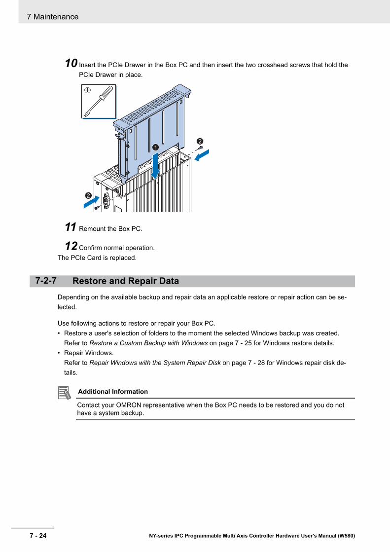
10 Insert the PCIe Drawer in the Box PC and then insert the two crosshead screws that hold thePCIe Drawer in place.
2
1
2
11 Remount the Box PC.
12 Confirm normal operation.The PCIe Card is replaced.
7-2-7 Restore and Repair DataDepending on the available backup and repair data an applicable restore or repair action can be se-lected.
Use following actions to restore or repair your Box PC.• Restore a user's selection of folders to the moment the selected Windows backup was created.
Refer to Restore a Custom Backup with Windows on page 7 - 25 for Windows restore details.• Repair Windows.
Refer to Repair Windows with the System Repair Disk on page 7 - 28 for Windows repair disk de-tails.
Additional Information
Contact your OMRON representative when the Box PC needs to be restored and you do nothave a system backup.
7 Maintenance
7 - 24 NY-series IPC Programmable Multi Axis Controller Hardware User's Manual (W580)
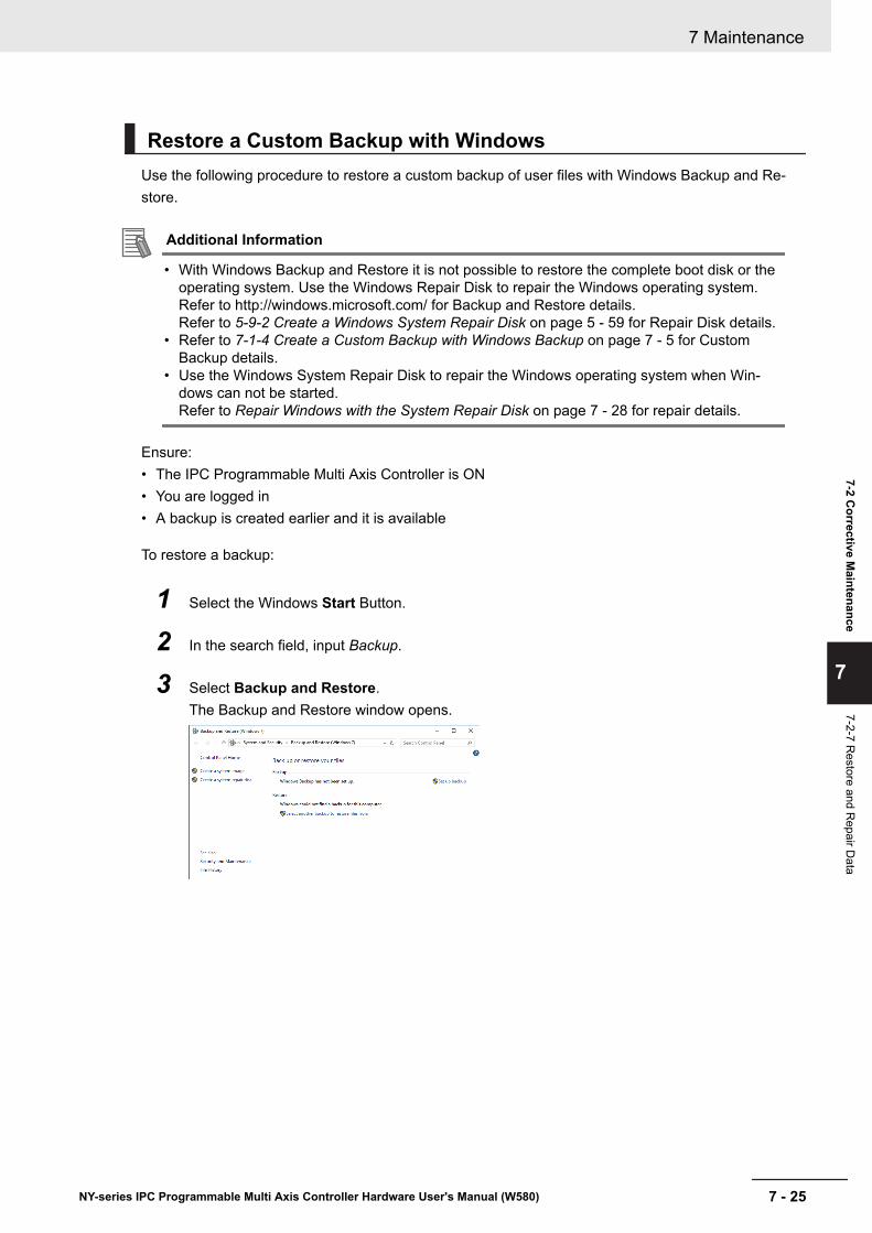
Restore a Custom Backup with WindowsUse the following procedure to restore a custom backup of user files with Windows Backup and Re-store.
Additional Information
• With Windows Backup and Restore it is not possible to restore the complete boot disk or theoperating system. Use the Windows Repair Disk to repair the Windows operating system.Refer to http://windows.microsoft.com/ for Backup and Restore details.Refer to 5-9-2 Create a Windows System Repair Disk on page 5 - 59 for Repair Disk details.
• Refer to 7-1-4 Create a Custom Backup with Windows Backup on page 7 - 5 for CustomBackup details.
• Use the Windows System Repair Disk to repair the Windows operating system when Win-dows can not be started.Refer to Repair Windows with the System Repair Disk on page 7 - 28 for repair details.
Ensure:• The IPC Programmable Multi Axis Controller is ON• You are logged in• A backup is created earlier and it is available
To restore a backup:
1 Select the Windows Start Button.
2 In the search field, input Backup.
3 Select Backup and Restore.The Backup and Restore window opens.
7 Maintenance
7 - 25NY-series IPC Programmable Multi Axis Controller Hardware User's Manual (W580)
7-2 Corrective M
aintenance
7
7-2-7 Restore and R
epair Data
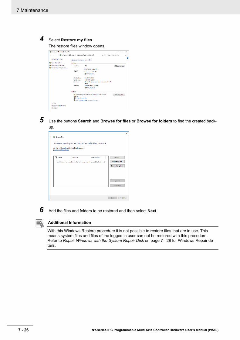
4 Select Restore my files.The restore files window opens.
5 Use the buttons Search and Browse for files or Browse for folders to find the created back-up.
6 Add the files and folders to be restored and then select Next.
Additional Information
With this Windows Restore procedure it is not possible to restore files that are in use. Thismeans system files and files of the logged in user can not be restored with this procedure.Refer to Repair Windows with the System Repair Disk on page 7 - 28 for Windows Repair de-tails.
7 Maintenance
7 - 26 NY-series IPC Programmable Multi Axis Controller Hardware User's Manual (W580)

7 Select In the original location and then select Next.The progress window will appear.
8 Wait until the message Your files have been restored appears and then select Finish.
The files are restored.
7 Maintenance
7 - 27NY-series IPC Programmable Multi Axis Controller Hardware User's Manual (W580)
7-2 Corrective M
aintenance
7
7-2-7 Restore and R
epair Data

Repair Windows with the System Repair DiskUse the following procedure to repair the Windows operating system with a System Repair Disk.
Ensure:• The IPC Programmable Multi Axis Controller is powered OFF.• A System Repair Disk is created earlier and it is available.
To perform a system repair:
1 Connect a USB keyboard, a USB mouse and a USB external DVD drive to the IPC Program-mable Multi Axis Controller.
2 Power ON the IPC Programmable Multi Axis Controller and immediately press the F11 key re-peatedly.
3 Insert the System Repair Disk in the DVD drive.
4 Select DVD Drive as boot device and press Enter.The message Windows is loading files ... and a progress bar appear.
5 Press any key to start and wait until the recovery software started.
6 Select your keyboard language and then select Next.The System Recovery Options window appears.
7 Select Restore your computer using a system image that you created earlier and selectNext.
8 Select Use latest available system image and then select Next.The Re-Image Your Computer window appears.
9 Do not change the setting to restore C: , select Next.
10 Review the settings and select Finish.
11 Wait until the repair process is finished, this can take several hours.
12 Restart the IPC Programmable Multi Axis Controller.Windows is repaired.
Additional Information
• Refer to http://windows.microsoft.com/ for System repair details.• Refer to 5-9-2 Create a Windows System Repair Disk on page 5 - 59 for System Repair disk
creation.• Refer to 5-9 Create a Windows System Repair Disk and a Windows Backup on page 5 - 59
for Backup creation.
7 Maintenance
7 - 28 NY-series IPC Programmable Multi Axis Controller Hardware User's Manual (W580)
7-2-8 Allocate a Drive in WindowsAn added drive must be allocated before it becomes visible in Windows.To allocate a drive in Windows:
1 Ensure the Box PC is ON.
2 Select the Windows Start Button.
3 In the search field, input partition.
4 Select Create and format hard disk partitions.The Disk Management window opens. The new disk is displayed with a storage spaceUnallocated.
5 Right click on the unallocated space and select New Simple Volume.The New Simple Volume Wizard opens.
6 Follow the steps in the New Simple Volume Wizard.The drive is installed and ready for use in Windows under the configured drive letter.
Additional Information
Do not format, resize or change settings for partition C:. Windows is installed on drive partitionC: and any change to this partition can cause Windows to stop working.
7 Maintenance
7 - 29NY-series IPC Programmable Multi Axis Controller Hardware User's Manual (W580)
7-2 Corrective M
aintenance
7
7-2-8 Allocate a Drive in W
indows

7-2-9 Windows Event ViewerThe Windows Event Viewer displays logged events.These logged events can support you in corrective maintenance.
1 Select the Windows Start Button.
2 In the search field, input Event.
3 Select View event logs.The Event Viewer opens.
A B C D
ItemA Selection treeB Event listC Event detailsD Action list
4 In the Selection tree expand Windows Logs and select Application.The Event list will display the Events.
5 Select the heading Source to sort the event messages per application.
6 Scroll to the event you want to investigate.Refer to the section 'Logging' of a specific utility for more details.
7 Select the event to display details in the Event details window or to take action in the Actionoverview window.
7 Maintenance
7 - 30 NY-series IPC Programmable Multi Axis Controller Hardware User's Manual (W580)
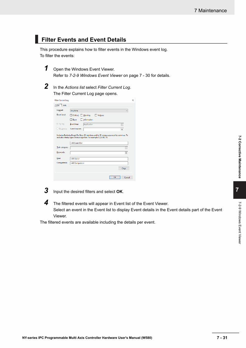
Filter Events and Event DetailsThis procedure explains how to filter events in the Windows event log.To filter the events:
1 Open the Windows Event Viewer.Refer to 7-2-9 Windows Event Viewer on page 7 - 30 for details.
2 In the Actions list select Filter Current Log.The Filter Current Log page opens.
3 Input the desired filters and select OK.
4 The filtered events will appear in Event list of the Event Viewer.Select an event in the Event list to display Event details in the Event details part of the EventViewer.
The filtered events are available including the details per event.
7 Maintenance
7 - 31NY-series IPC Programmable Multi Axis Controller Hardware User's Manual (W580)
7-2 Corrective M
aintenance
7
7-2-9 Window
s Event Viewer

7 Maintenance
7 - 32 NY-series IPC Programmable Multi Axis Controller Hardware User's Manual (W580)

AAppendices
A-1 BIOS ............................................................................................................. A - 2A-1-1 BIOS Overview .............................................................................................A - 2A-1-2 BIOS - Main ..................................................................................................A - 4A-1-3 BIOS - Advanced ..........................................................................................A - 5A-1-4 BIOS - Chipset..............................................................................................A - 8A-1-5 BIOS - Boot...................................................................................................A - 9A-1-6 BIOS - Security ...........................................................................................A - 10A-1-7 BIOS - Save & Exit .....................................................................................A - 10
A-2 Customize Windows ..................................................................................A - 11A-2-1 Enhanced Write Filter ................................................................................. A - 11A-2-2 File-Based Write Filter ................................................................................A - 12
A-3 DVI-I Connector Pin Details...................................................................... A - 14A-4 RS-232C Connector Pin Details ............................................................... A - 16
A - 1NY-series IPC Programmable Multi Axis Controller Hardware User's Manual (W580)
A
A-1 BIOSThis section provides the BIOS information of the IPC Programmable Multi Axis Controller.
WARNINGChanging BIOS information is only allowed for the engineer in chargethat possesses a thorough understanding of the BIOS settings becauseit can change the behavior of the product.
A-1-1 BIOS OverviewThe BIOS contains settings that influence the behavior of the IPC Programmable Multi Axis Controller.The touchscreen functionality is not functional when working in BIOS.Ensure a USB keyboard is connected.
BIOS Setup ProgramPress the DEL or F2 key repeatedly directly after Power ON to access the BIOS Setup Program.
Boot Selection Popup MenuPress the F11 key repeatedly directly after Power ON to display the Boot Selection Popup menu.The popup menu allows selection of the boot device and the option to enter the BIOS setup program.
BIOS StructureThe BIOS contains a menu bar, a left frame and a right frame.The left frame displays all the options that can be configured in the selected menu.The left frame uses following colors:• Blue = Configurable options• Greyed-out = Not configurable• Inverse white = SelectedThe right frame displays the key legend. Above the key legend is an area reserved for text messages.These text messages explain the options and the possible impacts when you change the selected op-tion in the left frame.
Use the àß keys to navigate between pages.
The menu bar gives access to following pages with settings:• Main
Refer to A-1-2 BIOS - Main on page A - 4 for Main details.• Advanced
Refer to A-1-3 BIOS - Advanced on page A - 5 for Advanced details.• Chipset
Refer to A-1-4 BIOS - Chipset on page A - 8 for Chipset details.• Boot
Appendices
A - 2 NY-series IPC Programmable Multi Axis Controller Hardware User's Manual (W580)

Refer to A-1-5 BIOS - Boot on page A - 9 for Boot details.• Security
Refer to A-1-6 BIOS - Security on page A - 10 for Security details.• Save & Exit
Refer to A-1-7 BIOS - Save & Exit on page A - 10 for Save and Exit details.
BIOS - Navigation and Function KeysThe right part of the BIOS screens is divided in two parts.
Top part.Provides additional information on selected screens or parameters.Bottom part.Provides information on Keys.• àß : Select Screen
Changed between different BIOS pages.• áâ : Select Item
Changed between different parameters.• Enter: Select
Selects the parameter that has the focus and displays a submenu or the possibility to change theparameter.
• + / - : Change OptionChange settings. A numerical value will be increased or decreased. A boolean value will toggle.
• F1: General HelpDisplays help information.
• F2: Previous ValuesChanges all parameters to the values they had when entering the BIOS.
• F9: Optimized DefaultsChanges all settings to the default values.
• F10: Save & ExitSaves all changes and exits the BIOS.
• ESC: ExitGo one level up. For parameters this is the previous level. For the main pages this exits the BIOS.
Appendices
A - 3NY-series IPC Programmable Multi Axis Controller Hardware User's Manual (W580)
A-1 B
IOS
A
A-1-1 BIOS O
verview

BIOS Password & Write ProtectionA BIOS password protects the BIOS setup program from unauthorized access. This ensures thatusers cannot change the system configuration without authorization. With an assigned BIOS pass-word, the BIOS prompts the user for a password on a setup entry. If the password entered is wrong,the BIOS setup program will not launch.The BIOS uses encryption for the password.The BIOS password is case sensitive with a minimum of 3 characters and a maximum of 20 charac-ters. Once a BIOS password has been assigned, the BIOS activates the grayed out BIOS Update andWrite Protection option. If this option is set to enabled, only authorized users (users with the correctpassword) can update the BIOS. With the BIOS password protection and the BIOS update and writeprotection, the system configuration is completely secured. If the BIOS is password protected, youcannot change the configuration of an end application without the correct password.
A-1-2 BIOS - MainThe main setup screen gives platform information about the BIOS, Board Information, Firmware Revi-sion, MAC Addresses and information about the number of Boots and the Running Time.
Changeable BIOS Main parameters and their factory default values:• System Date
Use the Enter key to the next Date field.• System Time
Use the Enter key to the next Time field.
Appendices
A - 4 NY-series IPC Programmable Multi Axis Controller Hardware User's Manual (W580)

A-1-3 BIOS - AdvancedThis section provides advanced BIOS information.
Changeable BIOS Advanced parameters and their factory default values:
Item Default / RemarkMachine Control EnabledGraphics Primary Graphics Device Auto
Internal Graphics Device AutoIGD Pre-Allocated Graphics Memory 32MIGD Total Graphics Memory 256MPrimary IGD Boot Display Device AutoActive LFP Configuration • eDP / for Industrial
Panel PC• No Local Flat Panel /
for Industrial Box PCDigital Display Interface 1 HDMI/DVIDigital Display Interface 2 HDMI/DVI
Hardware HealthMonitoring
Start Temperature 50 CTemperature Range 30 CMinimum Fan Speed 30% / FixedMaximum Fan Speed 100%Fan Always On At Minimum Speed Disabled
PCI & PCI Express PIRQ Routing & IRQ Res-ervation
PIRQA,B,C,D,E,F,G,H Auto
PCI Express Settings Relaxed Ordering DisabledExtended Tag DisabledNo Snoop EnabledMaximum Payload AutoMaximum Read Request AutoASPM DisabledExtended Synch DisabledLink Training Retry 5Link Training Timeout (us) 100Restore PCIe Registers Disabled
Appendices
A - 5NY-series IPC Programmable Multi Axis Controller Hardware User's Manual (W580)
A-1 B
IOS
A
A-1-3 BIOS - Advanced
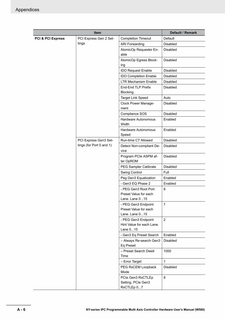
Item Default / RemarkPCI & PCI Express PCI Express Gen 2 Set-
tingsCompletion Timeout DefaultARI Forwarding DisabledAtomicOp Requester En-able
Disabled
AtomicOp Egress Block-ing
Disabled
IDO Request Enable DisabledIDO Completion Enable DisabledLTR Mechanism Enable DisabledEnd-End TLP PrefixBlocking
Disabled
Target Link Speed AutoClock Power Manage-ment
Disabled
Compliance SOS DisabledHardware AutonomousWidth
Enabled
Hardware AutonomousSpeed
Enabled
PCI Express Gen3 Set-tings (for Port 0 and 1)
Run-time C7 Allowed DisabledDetect Non-compliant De-vice
Disabled
Program PCIe ASPM af-ter OpROM
Disabled
PEG Sampler Calibrate DisabledSwing Control FullPeg Gen3 Equalization Enabled- Gen3 EQ Phase 2 Enabled- PEG Gen3 Root PortPreset Value for eachLane. Lane 0...15
8
- PEG Gen3 EndpointPreset Value for eachLane. Lane 0...15
7
- PEG Gen3 EndpointHint Value for each Lane.Lane 0...15
2
- Gen3 Eq Preset Search Enabled– Always Re-search Gen3Eq Preset
Disabled
– Preset Search DwellTime
1000
– Error Target 1PEG RxCEM LoopbackMode
Disabled
PCIe Gen3 RxCTLEpSetting. PCIe Gen3RxCTLEp 0...7
8
Appendices
A - 6 NY-series IPC Programmable Multi Axis Controller Hardware User's Manual (W580)

Item Default / RemarkPCI & PCI Express GbE Channel 0 PCI Express Port 0 Enabled
ASPM DisabledGbE Channel 1 PCI Express Port 1 Enabled
ASPM DisabledPCI Express Port 0, 1 (x4Gen3)
PEG1 Speed AutoPEG1 ASPM DisabledPEG1 De-emphasis Con-trol
-3.5 dB
PCI Express Port 2, 3, 4,5 (x1 Gen2)
PCI Express Port x EnabledASPM DisabledHot Plug DisabledPCIe Speed AutoDetect Non-compliant De-vice
Disabled
ACPI ACPI Sleep State S3 (Suspend to RAM)Lock Legacy Resources DisabledS3 Video Repost DisabledNative PCI Express Support Enabled- Native ASPM DisabledACPI Debug DisabledACPI 5.0 CPPC Support Disabled
RTC Wake Make System At Fixed Time DisabledTrusted Computing Trusted Computing information Display of Trusted Com-
puting parametersCPU CPU information Display of CPU parame-
tersSATA SATA information Display of SATA parame-
tersMemory Configuration Memory Configuration information Display of Memory Con-
figuration parametersIntel (R) Rapid StartTechnology
Intel Rapid Start information Display of Intel RapidStart parameters
USB XHCI Mode Smart AutoOvercurrent Protection DisabledUSB Ports Per-Port Disa-ble Control
USB Ports Per-Port Disa-ble Control
Enabled
- USB Port 0...6 Enabled- USB 3.0 Port 0...1 Enabled
Legacy USB Support EnabledExternal USB Controllers Support EnabledXHCI Hand-off EnabledEHCI Hand-off DisabledUSB Mass Storage Driver Support EnabledUSB Transfer Timeout 20 secDevice Reset Timeout 20 secDevice Power-up Delay Selection AutoGeneric Ultra HS-COMBO Auto
SMART Settings Smart Self Test *1 Disabled
Appendices
A - 7NY-series IPC Programmable Multi Axis Controller Hardware User's Manual (W580)
A-1 B
IOS
A
A-1-3 BIOS - Advanced
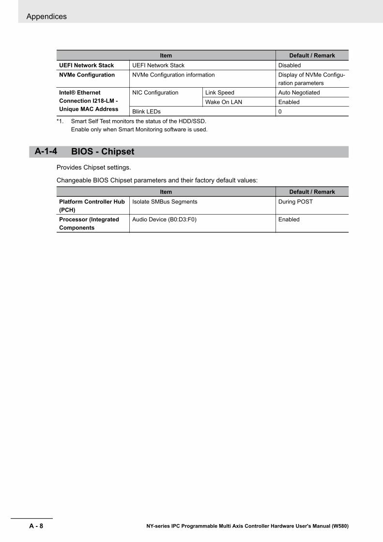
Item Default / RemarkUEFI Network Stack UEFI Network Stack DisabledNVMe Configuration NVMe Configuration information Display of NVMe Configu-
ration parametersIntel® EthernetConnection I218-LM -Unique MAC Address
NIC Configuration Link Speed Auto NegotiatedWake On LAN Enabled
Blink LEDs 0*1. Smart Self Test monitors the status of the HDD/SSD.
Enable only when Smart Monitoring software is used.
A-1-4 BIOS - ChipsetProvides Chipset settings.
Changeable BIOS Chipset parameters and their factory default values:
Item Default / RemarkPlatform Controller Hub(PCH)
Isolate SMBus Segments During POST
Processor (IntegratedComponents
Audio Device (B0:D3:F0) Enabled
Appendices
A - 8 NY-series IPC Programmable Multi Axis Controller Hardware User's Manual (W580)

A-1-5 BIOS - BootProvides Boot information and configuration settings.
Changeable BIOS Boot parameters and their factory default values:
Item Default / RemarkQuiet Boot DisabledSetup Prompt Timeout 1Bootup NumLock State OnBattery Support Auto (Battery Manager)
Power Loss Control *1 Remain Off
CSM & Option ROM Control Launch CSM EnabledBoot Option Filter UEFI and LegacyPXE Option ROM Launch Policy UEFI ROM OnlyStorage Option ROM Launch Policy Legacy ROM OnlyVideo Option ROM Launch Policy Legacy ROM OnlyOther Option ROM Launch Policy UEFI ROM OnlyGate A20 Active Upon RequestOption ROM Messages Force BIOS
Enter Setup If No Boot Device NoEnable Popup Boot Menu YesType Based Boot Priority 1st Boot Device SATA 2 Drive
2nd Boot Device Disabled3rd Boot Device Disabled4th Boot Device Disabled5th Boot Device Disabled6th Boot Device Disabled7th Boot Device Disabled8th Boot Device Disabled
UEFI Fast Boot Disabled*1. Power Loss Control settings are :
Remain OFF: The Box PC will stay OFF when power is supplied to the power connectorTurn ON: The Box PC will automatically start up when power is supplied to the power connector.Last State: The Box PC will start up or remain OFF when power is supplied based on the Box PC state atthe moment power was removed from the power connector.
Appendices
A - 9NY-series IPC Programmable Multi Axis Controller Hardware User's Manual (W580)
A-1 B
IOS
A
A-1-5 BIOS - Boot

A-1-6 BIOS - SecurityProvides security information like BIOS Password and HDD information.
WARNINGSecurity setting adjustments should only be performed by the engineerin charge that possesses a thorough understanding of the security set-tings. Selecting non-recommended security settings can put your sys-tem at risk.
Changeable BIOS Security parameters and their factory default values:
Item Default / RemarkBIOS Password EmptyBIOS Lock EnabledHDD SecurityConfiguration
Diskname Display disk parameters
Secure Boot Menu Secure Boot DisabledSecure Boot Mode CustomKey Management Default Key Provision Disabled
Platform Key (PK) NOT INSTALLEDKey Exchange Key (KEK) NOT INSTALLEDAuthorized Signatures NOT INSTALLEDForbidden Signatures NOT INSTALLEDAuthorized TimeStamps NOT INSTALLED
A-1-7 BIOS - Save & ExitProvides the possibility to leave the BIOS with or without saving changes.
Save & Exit Parameters: Disabled.• Save Changes and Exit
Changed settings are saved and the Operating System starts with the changed settings.• Discard Changes and Exit
Changed settings are not saved and the Operating System starts with the unchanged settings.• Save Changes and Reset
Changed settings are saved and the Box PC restarts using the changed settings.• Discard Changes and Reset
Changed settings are not saved and the Box PC restarts with the unchanged settings.• Save Changes
Changed settings are saved and the BIOS setup stays open.• Discard Changes
Changed settings are reverted to their last saved values and the BIOS setup stays open.• Restore Defaults
Revert all BIOS settings to factory default.
Appendices
A - 10 NY-series IPC Programmable Multi Axis Controller Hardware User's Manual (W580)
A-2 Customize WindowsThis section provides an overview of the tools to customize Windows.
A-2-1 Enhanced Write FilterThe Enhanced Write Filter (EWF) is applicable to Box PCs with a Windows 7 operating system.The Enhanced Write Filter (EWF) intercepts disk changes and stores them into a memory overlay inRAM memory instead of applying them to the original volume.
Additional Information
• File-Based Write Filter (FBWF) provides a similar function, but operates at the file level, whileEWF operates at the sector level.
• Refer to the Microsoft Developer Network (MSDN) for detailed information.
ApplicationEWF and FBWF provide the following benefits:• Write-protect one or more partitions on a system.• Make it possible to revert changes and revert to the original disk content.• Enable booting from read-only media.
By redirecting all write requests to RAM, EWF and FBWF enable the run-time image to maintain theappearance of a writable run-time image.
• Improve the file system performance when using relatively slow storage.• Minimize write actions to the disk.
For example, minimize write access to flash memory. Write cycles on flash memory are limited fortechnical reasons.
UsageEWF is included in the Windows Embedded Standard 7 image and disabled by default. The configura-tion of this component can be defined with the command line tool EWFMGR.EXE.To run to EWF Manager, open the Command Prompt with Administrator rights.
Command Function Remarksewfmgr Shows an overview with current
status.---
ewfmgr c: -enable Enables the write filter for the driveC:.
The protection is not effective untilthe system is restarted.
ewfmgr c: -commit Writes all the changes in the mem-ory overlay to the physical disk dur-ing the next restart.
Committing the overlay can affectthe speed of the boot process.
ewfmgr c: -commitanddisable Writes all the changes in the mem-ory overlay to the physical disk dur-ing the next restart, and disablesthe disk protection.
Committing the overlay can affectthe speed of the boot process.The protection is not disabled untilthe system is restarted.
Appendices
A - 11NY-series IPC Programmable Multi Axis Controller Hardware User's Manual (W580)
A-2 C
ustomize W
indows
A
A-2-1 Enhanced Write Filter

Command Function Remarksewfmgr c: -commitanddisable -live
Writes all the changes in the mem-ory overlay to the physical disk im-mediately, and disables the diskprotection.
Protection is also disabled immedi-ately. No restart is required.
ewfmgr c: -disable Disables the disk protection. The protection is not disabled untilthe system is restarted.
ewfmgr /h Displays a helpscreen that explainsall commands and options availa-ble.
A complete reference can also befound at the Microsoft DeveloperNetwork (MSDN).
Considerations• EWF and FBWF cannot be used simultaneously.• To prevent data loss in the event of a power failure, the use of a UPS is recommended.• When the EWF function is enabled and a large amount of data is written, the system memory space
will be reduced and operation may become unstable. To prevent this problem, it is recommendedthat a large amount of data be written to a different location.
• Automatic Adjustment of daylight saving time (DST) is incompatible with the Enhanced Write Filter(EWF).
Additional Information
Refer to the Microsoft Developer Network (MSDN) for DST details.
A-2-2 File-Based Write FilterThe File-Based Write Filter (FBWF) is applicable to Box PCs with a Windows 7 operating system.The File-Based Write Filter (FBWF) intercepts file changes and stores them into a memory overlay inRAM memory instead of applying them to the original volume.When FBWF is enabled, all files and folders of a partition are protected unless they are included in anexception list.
Additional Information
• Enhanced Write Filter (EWF) provides a similar function, but operates at the sector level,while FBWF operates at the file level. FBWF is more flexible in its configuration than EWFand allows immediate writing without rebooting.
• Refer to the Microsoft Developer Network (MSDN) for detailed information.
ApplicationEWF and FBWF provide the following benefits:• Write-protect one or more partitions on a system.• Make it possible to revert changes and revert to the original disk content.• Enable booting from read-only media.
By redirecting all write requests to RAM, EWF and FBWF enable the run-time image to maintain theappearance of a writable run-time image.
• Improve the file system performance when using relatively slow storage.
Appendices
A - 12 NY-series IPC Programmable Multi Axis Controller Hardware User's Manual (W580)

• Minimize write actions to the disk.For example, minimize write access to flash memory. Write cycles on flash memory are limited fortechnical reasons.
UsageFBWF is included in the Windows Embedded Standard 7 image and disabled by default. The configu-ration of this component can be defined with the command line tool FBWFMGR.EXE.To run to FBWF Manager, open the Command Prompt with Administrator rights.
Command Function Remarksfbwfmgr Shows an overview with current
status.---
fbwfmgr /displayconfig Shows current configuration. ---
fbwfmgr /enable Enables the write filter. The protection is not effective untilthe system is restarted.
fbwfmgr /addvolume c: Adds a volume to the protected vol-ume list.
That volume will be protected afterthe next restart.
fbwfmgr /commit c: \Test.txt Writes the changes to the protectedfile/folder.
---
fbwfmgr /addexclusion C:\Test.txt
Adds a write-through path to theexclusion list (file/folder).
The exclusion is active after thenext restart.
fbwfmgr /removeexclusion C:\Test.txt
Removes the write-through pathfrom the exclusion list (file/folder).
The exclusion is removed after thenext restart.
fbwfmgr /h Displays a helpscreen that explainsall commands and options availa-ble.
A complete reference can also befound at the Microsoft DeveloperNetwork (MSDN).
Additional Information
When specifying a file name, notice the space between drive name (c:) and file path (\Test.txt).
Considerations• EWF and FBWF cannot be used simultaneously.• FBWF can only protect formatted volumes. Do not move files between protected and unprotected
volumes.• When the FBWF function is enabled and a large amount of data is written, the system memory
space will be reduced and operation may become unstable. To prevent this problem, it is recom-mended that a large amount of data be written to a different location.
• FBWF supports only NTFS and FAT32 file systems.• Automatic Adjustment of daylight saving time (DST) is incompatible with the File-Based Write Filter
(FBWF).
Additional Information
Refer to the Microsoft Developer Network (MSDN) for DST details.
Appendices
A - 13NY-series IPC Programmable Multi Axis Controller Hardware User's Manual (W580)
A-2 C
ustomize W
indows
A
A-2-2 File-Based Write Filter

A-3 DVI-I Connector Pin DetailsPin details of the DVI-I connector.
1 8
C1 C2
C3 C4
9 16
17 24
C5
The pin layout represents the DVI-I connector on the IPC Programmable Multi Axis Controller.Pin numbers increase from left to right for every row.
Pin Signal Name Function1 TMDS data 2− Digital red− (link 1)2 TMDS data 2+ Digital red+ (link 1)3 0 VDC TMDS data 2/4 shield4 Not connected ---5 Not connected ---6 DDC clock DDC clock7 DDC data DDC data8 Analog vertical sync For Intel® Core™ i7-4700EQ CPU type9 TMDS data 1− Digital green− (link 1)10 TMDS data 1+ Digital green+ (link 1)11 0 VDC TMDS data 1/3 shield12 Not connected ---13 Not connected ---14 +5 V Power for monitor DDC interface15 0 V Return for pin 14 and analog sync16 HPD Hot Plug Detect17 TMDS data 0− Digital blue− (link 1) and digital sync18 TMDS data 0+ Digital blue+ (link 1) and digital sync19 0 VDC TMDS data 0/5 shield20 Not connected ---21 Not connected ---22 0 VDC TMDS clock shield23 TMDS clock+ Digital clock+24 TMDS clock− Digital clock−C1 Analog red For Intel® Core™ i7-4700EQ CPU typeC2 Analog green For Intel® Core™ i7-4700EQ CPU type
Appendices
A - 14 NY-series IPC Programmable Multi Axis Controller Hardware User's Manual (W580)
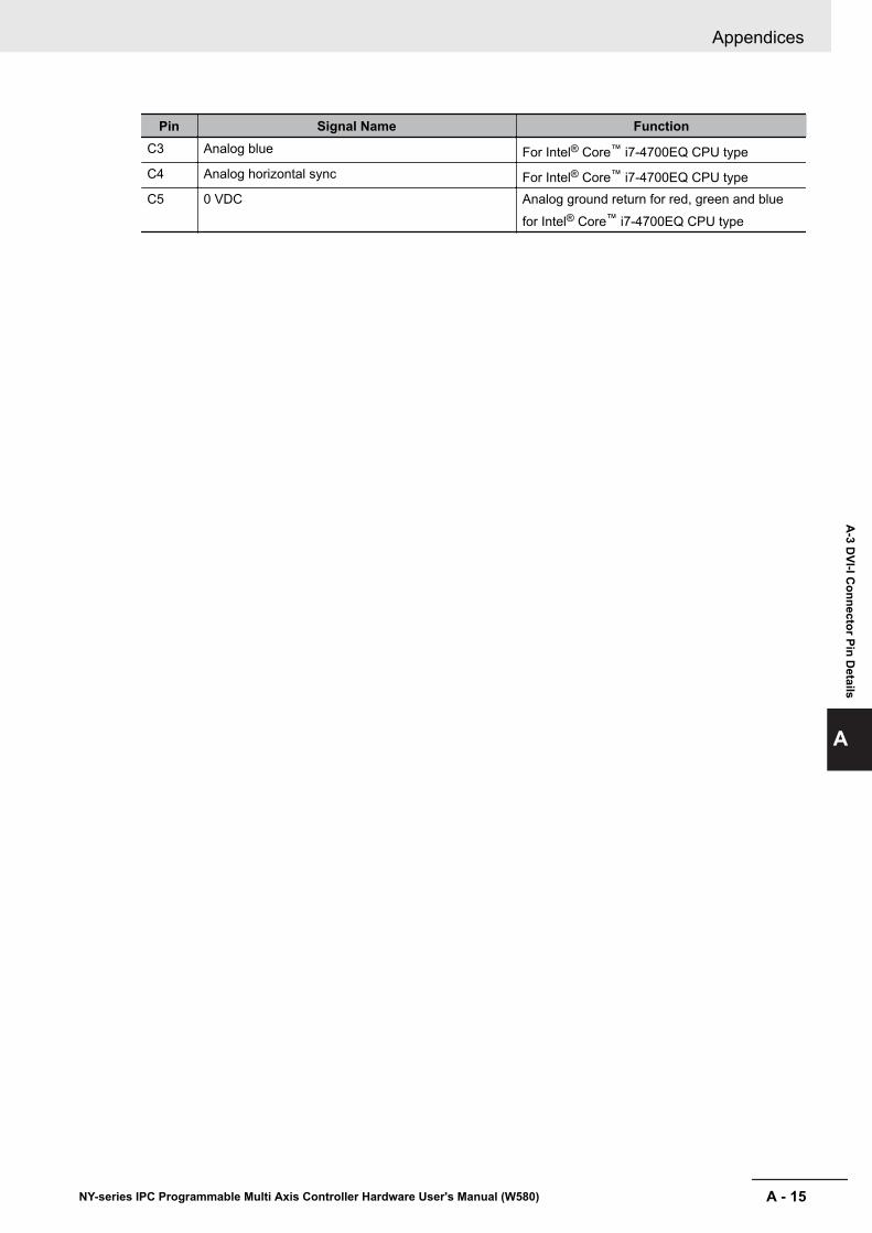
Pin Signal Name FunctionC3 Analog blue For Intel® Core™ i7-4700EQ CPU typeC4 Analog horizontal sync For Intel® Core™ i7-4700EQ CPU typeC5 0 VDC Analog ground return for red, green and blue
for Intel® Core™ i7-4700EQ CPU type
Appendices
A - 15NY-series IPC Programmable Multi Axis Controller Hardware User's Manual (W580)
A-3 D
VI-I Connector Pin D
etails
A
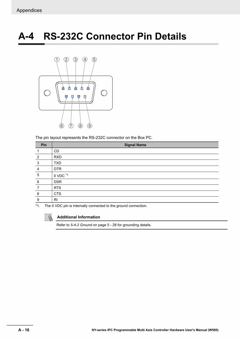
A-4 RS-232C Connector Pin Details
1 2 3 4 5
6 7 8 9
The pin layout represents the RS-232C connector on the Box PC.
Pin Signal Name1 CD2 RXD3 TXD4 DTR5 0 VDC *1
6 DSR7 RTS8 CTS9 RI
*1. The 0 VDC pin is internally connected to the ground connection.
Additional Information
Refer to 5-4-2 Ground on page 5 - 28 for grounding details.
Appendices
A - 16 NY-series IPC Programmable Multi Axis Controller Hardware User's Manual (W580)
IIndex
I - 1NY-series IPC Programmable Multi Axis Controller Hardware User's Manual (W580)
I

IndexA
Accessory kit ................................................................ 2 - 18Anti-virus software ........................................................ 5 - 50
B
Backup.................................................................. 5 - 59,7 - 5Battery ................................................................ 2 - 17,7 - 10
Replace .....................................................................7 - 13Replacement .............................................................7 - 10
Battery low ......................................................................2 - 8BIOS ...............................................................................A - 2Book mount .................................................................. 2 - 19Book mounting ..............................................................5 - 25Brackets
Scope of delivery ........................................................ 5 - 5Specifications ..............................................................4 - 8
Browser ........................................................................ 5 - 49
C
CablesCommunication S8BW ..............................................2 - 23DVI cables .................................................................2 - 21USB Type-A - USB Type-B cable ..............................2 - 21
Configuration .................................................................. 1 - 6Connect ........................................................................ 5 - 41Cooling distance ........................................................... 5 - 16Corrective maintenance ..................................................7 - 8Cover............................................................................. 7 - 10CPU
Intel® Core™ i7-4700EQ ............................................. 4 - 5
D
Dimensions .....................................................................4 - 2Drive
Install ...........................................................................5 - 6Install in Windows ..................................................... 7 - 29Replace .....................................................................7 - 15
Drivers .......................................................................... 5 - 51Ducts ............................................................................ 5 - 24DVI connector ...............................................................2 - 15
Specifications ............................................................4 - 18
E
ElectricalSpecifications ..............................................................4 - 3
Enhanced Write Filter (EWF) ........................................A - 11ERR LED ........................................................................ 2 - 8EtherCAT ...................................................................... 4 - 16Ethernet ........................................................................ 4 - 17Ethernet connectors ..................................................... 2 - 15
Link/Act Indicator ...................................................... 4 - 16
Specifications ............................................................4 - 15Speed Indicator .........................................................4 - 16
Event viewer.................................................................. 7 - 30Filter events .............................................................. 7 - 31
F
Fan error .........................................................................2 - 8Fan Unit ........................................................................ 2 - 17
Replace ..................................................................... 7 - 11File-Based Write Filter (FBWF) .................................... A - 12Firewall ......................................................................... 5 - 50
H
HDD ..............................................................................2 - 20HDD LED ........................................................................2 - 8Humidity ........................................................................4 - 22
I
I/O connector ................................................................ 2 - 13Connections .............................................................. 5 - 38Specifications ............................................................4 - 10Wiring ..............................................................5 - 38,5 - 40
Industrial PC Support Utility ............................................3 - 6Production data ...........................................................3 - 7System status ............................................................. 3 - 8
Industrial PC Tray Utility ............................................... 3 - 10
L
Languages ....................................................................4 - 20LED Indicators ................................................................ 2 - 7Logging
Event viewer ............................................................. 7 - 30Messages ....................................................................3 - 9
M
Memory ...........................................................................4 - 5Memory Card................................................................. 2 - 11Message
Error ............................................................................ 7 - 8Warning .......................................................................7 - 8
MessagesProduct ........................................................................6 - 5Windows ..................................................................... 6 - 6
Modbus-TCP ................................................................ 4 - 17Monitor ..........................................................................2 - 22Mounting
Book mount ...............................................................5 - 25Brackets .................................................................... 2 - 19Wall mount ................................................................ 5 - 26
Index
I - 2 NY-series IPC Programmable Multi Axis Controller Hardware User's Manual (W580)
O
Operating system ......................................................... 4 - 20License key ............................................................... 7 - 10Windows...................................................................... 3 - 2
P
PCIe Card .....................................................................2 - 12Install .........................................................................5 - 10Replace .....................................................................7 - 20Specifications ..............................................................4 - 7
Power Attendant Lite Utility .......................................... 3 - 13Power button .................................................................. 2 - 9Power connector ...........................................................2 - 13
Specifications ..............................................................4 - 9Wiring ..............................................................5 - 35,5 - 37
Power consumption ........................................................ 4 - 4Power OFF ..................................................................... 6 - 3
Forced with power button ............................................6 - 3Power ON ....................................................................... 6 - 2
Automatic .................................................................... 6 - 2Details ....................................................................... 4 - 12First time ................................................................... 5 - 45Input signal ..................................................................6 - 2Power button ...............................................................6 - 2
Power PMAC Support Utility............................................3 - 5Power supply ................................................................ 2 - 22
Overvoltage error ........................................................ 2 - 8Undervoltage error ...................................................... 2 - 8
Preventive maintenance ................................................. 7 - 2Product ........................................................................... 1 - 6PWR LED ....................................................................... 2 - 7
R
Repair ........................................................................... 7 - 24Restore ...............................................................7 - 24,7 - 25
System repair ............................................................7 - 28RS-232C connector ...................................................... 2 - 16
Specifications ............................................................4 - 19RUN LED.........................................................................2 - 8
S
Scope of delivery............................................................. 5 - 3SD Memory Card.................................................2 - 11,2 - 19Software
Install .........................................................................5 - 51Update ........................................................................ 7 - 4
SSD .............................................................................. 2 - 20Specifications ..............................................................4 - 6
Stand-by mode ............................................................... 2 - 7Startup .......................................................................... 5 - 47Storage devices ............................................................2 - 20
Specifications ..............................................................4 - 6System API ...................................................................3 - 16
T
Temperature ................................................................. 4 - 22Thermal shutdown .......................................................... 2 - 8
U
Unpack ........................................................................... 5 - 3UPS .................................................................... 2 - 23,5 - 52
Connect I/O................................................................5 - 56Connect USB............................................................. 5 - 53
USB connectors ............................................................2 - 14Specifications ............................................................4 - 14
USB flash drives ........................................................... 2 - 20
W
Wall mount ....................................................................2 - 19Wall mounting ...............................................................5 - 26Watchdog error ...............................................................2 - 8Weights ...........................................................................4 - 2Windows
Customize .................................................................A - 11Windows system repair disk ......................................... 5 - 59Wire .............................................................................. 5 - 27Wiring
Warnings ...................................................................5 - 27
Index
I - 3NY-series IPC Programmable Multi Axis Controller Hardware User's Manual (W580)
I


Authorized Distributor:
In the interest of product improvement, specifications are subject to change without notice.
Cat. No. W580-E2-03 0717
© OMRON Corporation 2016-2017 All Rights Reserved.
OMRON Corporation Industrial Automation Company
OMRON ELECTRONICS LLC2895 Greenspoint Parkway, Suite 200 Hoffman Estates, IL 60169 U.S.A.Tel: (1) 847-843-7900/Fax: (1) 847-843-7787
Regional Headquarters
OMRON EUROPE B.V.Wegalaan 67-69, 2132 JD HoofddorpThe NetherlandsTel: (31)2356-81-300/Fax: (31)2356-81-388
Contact: www.ia.omron.com
Kyoto, JAPAN
OMRON ASIA PACIFIC PTE. LTD.No. 438A Alexandra Road # 05-05/08 (Lobby 2), Alexandra Technopark, Singapore 119967Tel: (65) 6835-3011/Fax: (65) 6835-2711
OMRON (CHINA) CO., LTD.Room 2211, Bank of China Tower, 200 Yin Cheng Zhong Road, PuDong New Area, Shanghai, 200120, ChinaTel: (86) 21-5037-2222/Fax: (86) 21-5037-2200