nxp powerpoint template confidential 4:3 ratiocallotj/e1_2018/nxp/2018_automotiveelec_y... · -...
TRANSCRIPT
EXTERNAL USE
YVES BRIANT
FIELD APPLICATION ENGINEER
18TH, JANUARY, 2018
AUTOMOTIVE
ELECTRONICS
1 EXTERNAL USE
AUTOMOTIVE ELECTRONICS : AGENDA
1) Automotive electronics and semiconductor:
• Trends
• Specificities
• Technology
• Examples of application
• Functional Safety
2) Dissection of an automotive Microcontroler
• Core, Memories, Internal bus, Peripherals
• Dual-core, lock-step architecture
2 EXTERNAL USE
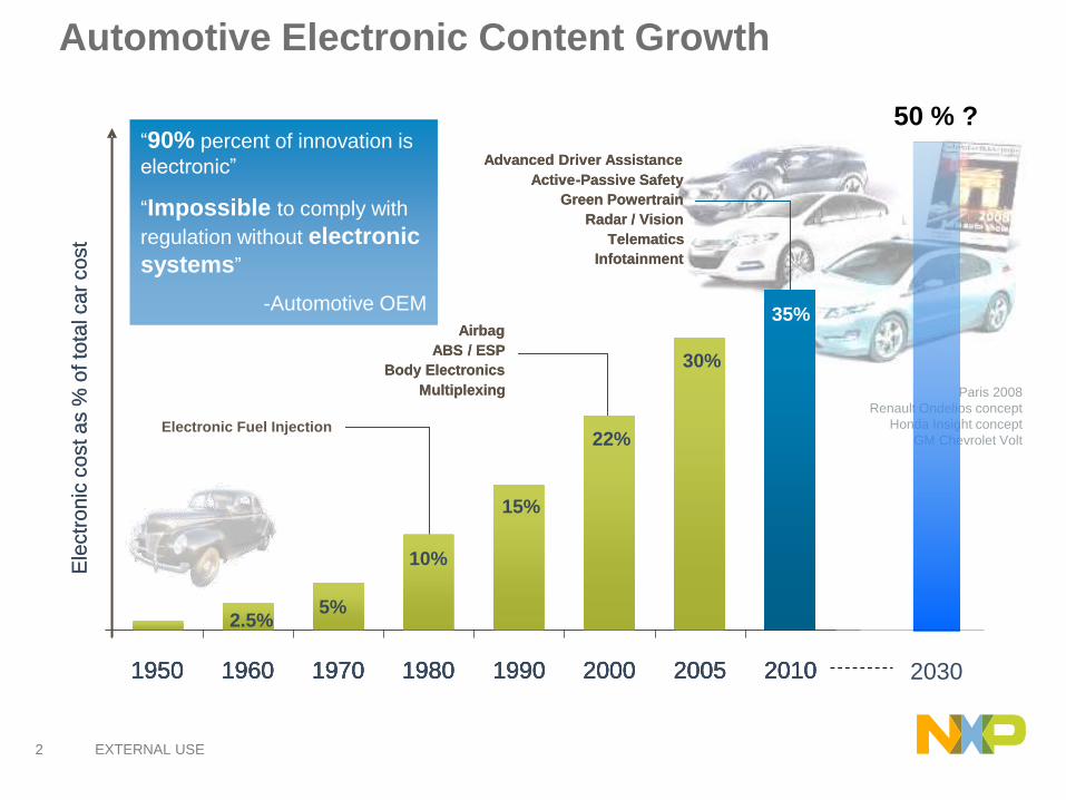
Automotive Electronic Content Growth
“90% percent of innovation is
electronic”
“Impossible to comply with
regulation without electronic
systems”
-Automotive OEM
Paris 2008
Renault Ondelios concept
Honda Insight concept
GM Chevrolet Volt
50 % ?
Ele
ctr
on
ic c
ost a
s %
of to
tal ca
r co
st
Airbag
ABS / ESP
Body Electronics
Multiplexing
Electronic Fuel Injection
1950 1960 1970 1980 1990 2000 2005 2010
35%
30%
22%
15%
10%
5%2.5%
1950 1960 1970 1980 1990 2000 2005 2010
35%
30%
22%
15%
10%
5%2.5%
Advanced Driver Assistance
Active-Passive Safety
Green Powertrain
Radar / Vision
Telematics
Infotainment
2030

3 EXTERNAL USE
THIS TREND WILL CONTINUE
90% OF ALL AUTOMOTIVE INNOVATIONS ARE ENABLED BY ELECTRONICS
5 EXTERNAL USE
6 EXTERNAL USE
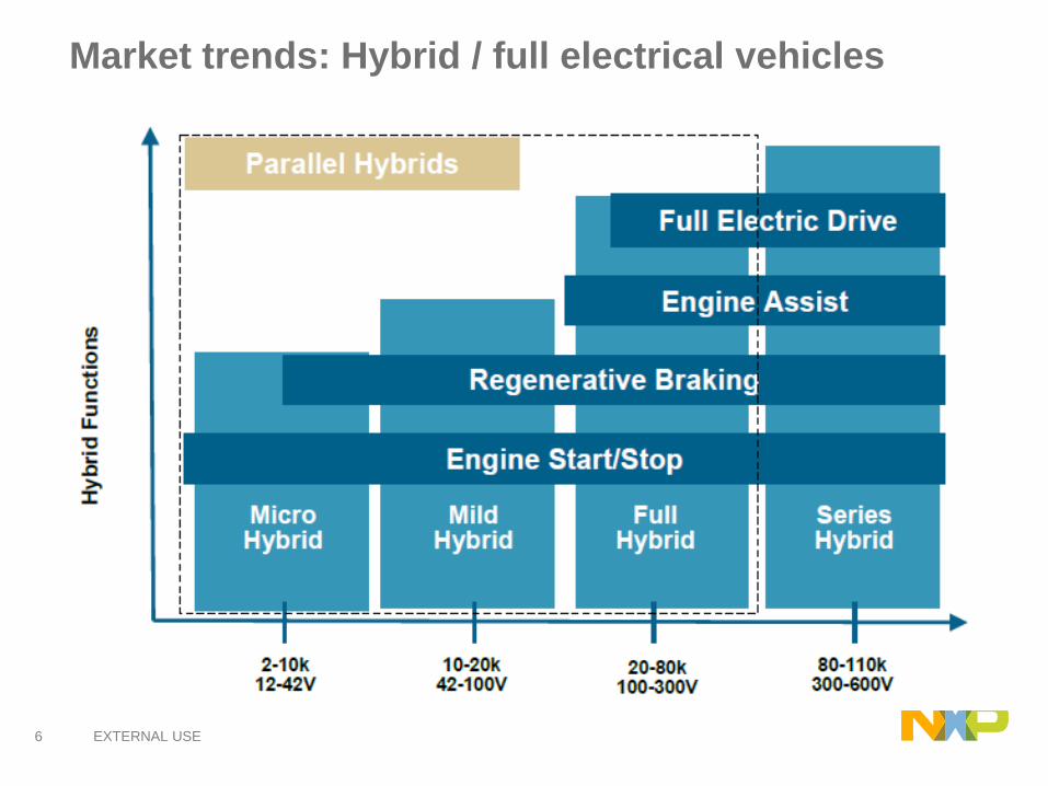
Market trends: Hybrid / full electrical vehicles
6
7 EXTERNAL USE
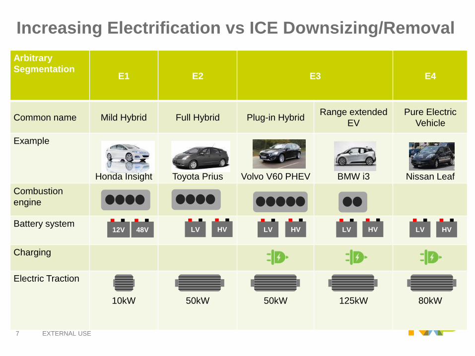
Increasing Electrification vs ICE Downsizing/Removal
Arbitrary
SegmentationE1 E2 E3 E4
Common name Mild Hybrid Full Hybrid Plug-in HybridRange extended
EV
Pure Electric
Vehicle
Example
Honda Insight Toyota Prius Volvo V60 PHEV BMW i3 Nissan Leaf
Combustion
engine
Battery system
Charging
Electric Traction
10kW 50kW 50kW 125kW 80kW
48V HV HV HV HVLV LVLVLV12V
8 EXTERNAL USE
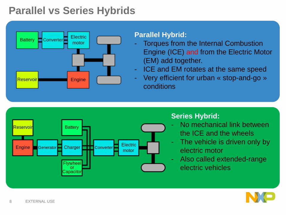
Parallel vs Series Hybrids
Parallel Hybrid:
- Torques from the Internal Combustion
Engine (ICE) and from the Electric Motor
(EM) add together.
- ICE and EM rotates at the same speed
- Very efficient for urban « stop-and-go »
conditions
Series Hybrid:
- No mechanical link between
the ICE and the wheels
- The vehicle is driven only by
electric motor
- Also called extended-range
electric vehicles

9 EXTERNAL USE
Market trends: Hybrid / full electrical vehicles
9
10 EXTERNAL USE
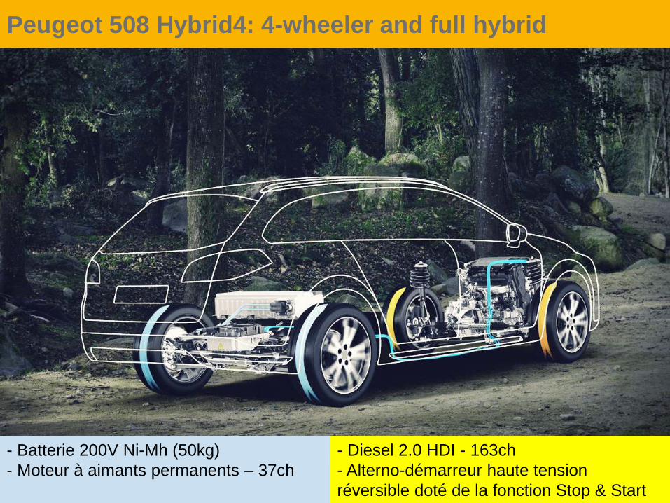
Peugeot 508 Hybrid4: 4-wheeler and full hybrid
- Diesel 2.0 HDI - 163ch
- Alterno-démarreur haute tension
réversible doté de la fonction Stop & Start
- Batterie 200V Ni-Mh (50kg)
- Moteur à aimants permanents – 37ch
11 EXTERNAL USE
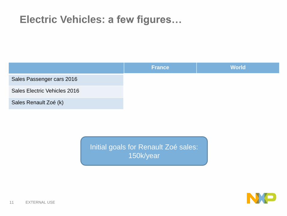
Electric Vehicles: a few figures…
France World
Sales Passenger cars 2016 2.015.186 75-80 M
Sales Electric Vehicles 2016 21.800 750.000
Sales Renault Zoé (k) 11.400 24.000
Initial goals for Renault Zoé sales:
150k/year
12 EXTERNAL USE
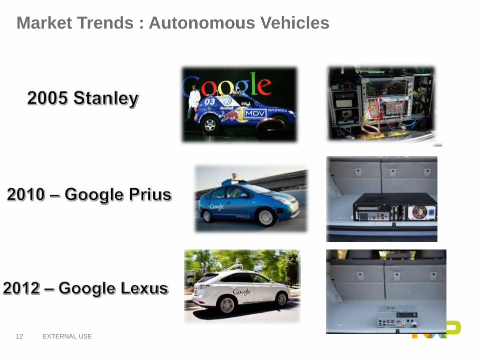
Market Trends : Autonomous Vehicles
13 EXTERNAL USE
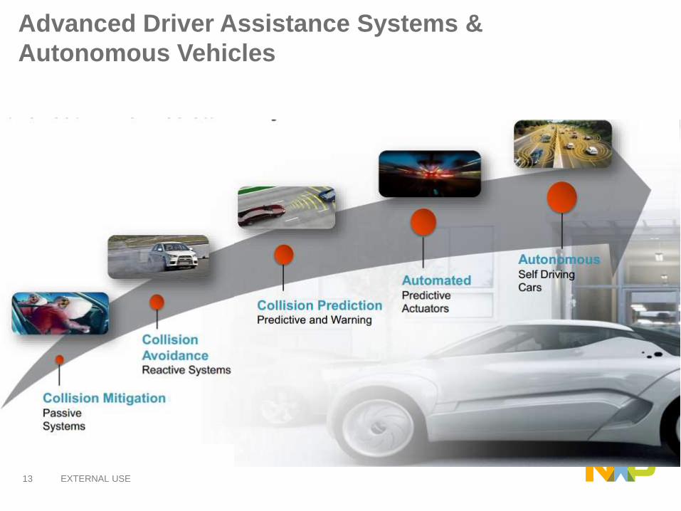
Advanced Driver Assistance Systems &
Autonomous Vehicles

14 EXTERNAL USE
Simplified Autonomous Vehicle Model

15 EXTERNAL USE
Vehicle-to-X Communication:
Saves Lives, Reduces CO2, Reduces Congestion
A paradigm shift in mobility
• Intelligence Transport
System (ITS):
A solution to avoid road
accidents, improve traffic
flow and enable
autonomous driving
Example: Intersection Movement Assist
17 EXTERNAL USE
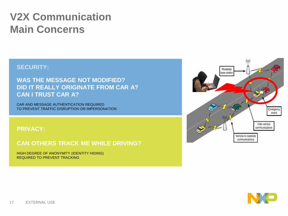
V2X Communication
Main Concerns
PRIVACY:
CAN OTHERS TRACK ME WHILE DRIVING?
HIGH DEGREE OF ANONYMITY (IDENTITY HIDING)
REQUIRED TO PREVENT TRACKING
SECURITY:
WAS THE MESSAGE NOT MODIFIED?
DID IT REALLY ORIGINATE FROM CAR A?
CAN I TRUST CAR A?
CAR AND MESSAGE AUTHENTICATION REQUIRED
TO PREVENT TRAFFIC DISRUPTION OR IMPERSONATION

18 EXTERNAL USE
AUTOMOTIVE ELECTRONICS : AGENDA
1) Automotive electronics and semiconductor:
• Trends
• Specificities
• Technology
• Examples of application
• Functional Safety
2) Dissection of an automotive Microcontroler
• Core, Memories, Internal bus, Peripherals
• Dual-core, lock-step architecture
19 EXTERNAL USE
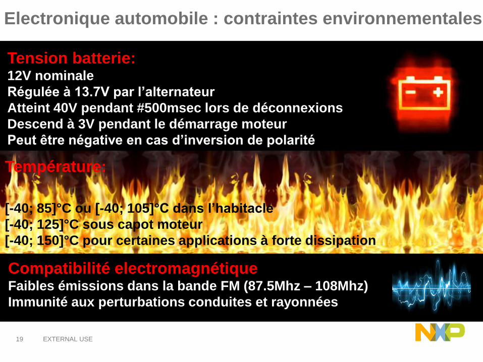
Electronique automobile : contraintes environnementales
Température:
[-40; 85]°C ou [-40; 105]°C dans l’habitacle
[-40; 125]°C sous capot moteur
[-40; 150]°C pour certaines applications à forte dissipation
Compatibilité electromagnétiqueFaibles émissions dans la bande FM (87.5Mhz – 108Mhz)
Immunité aux perturbations conduites et rayonnées
Tension batterie:12V nominale
Régulée à 13.7V par l’alternateur
Atteint 40V pendant #500msec lors de déconnexions
Descend à 3V pendant le démarrage moteur
Peut être négative en cas d’inversion de polarité
20 EXTERNAL USE
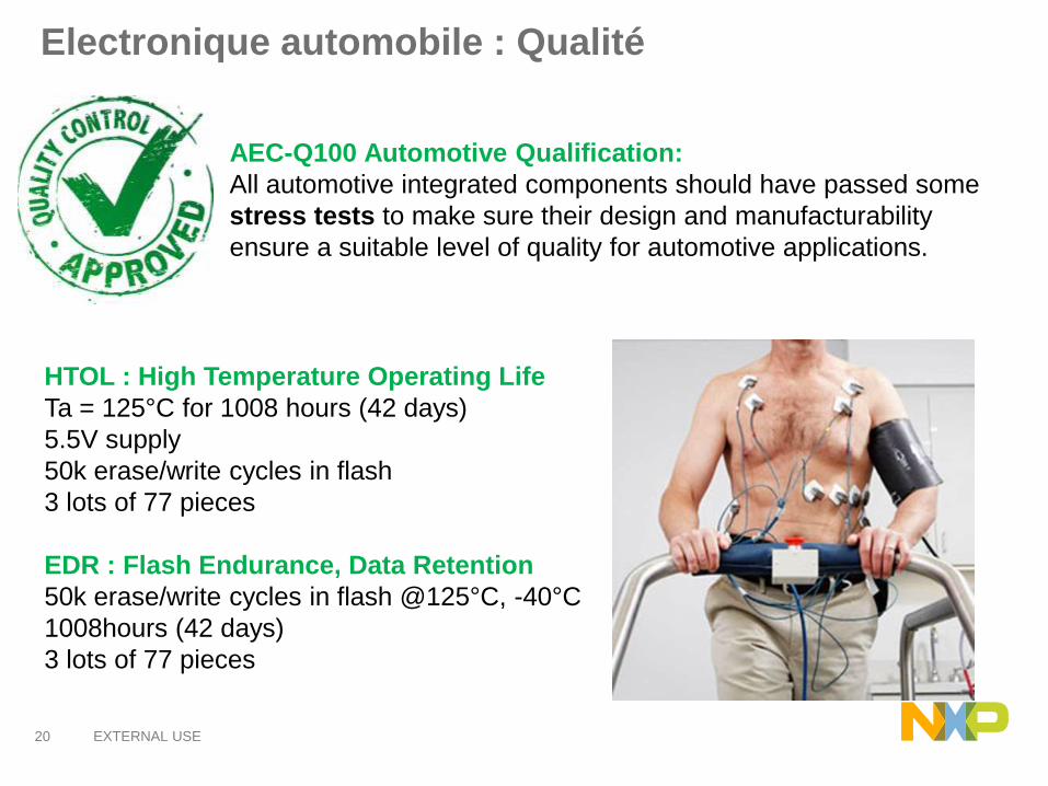
Electronique automobile : Qualité
AEC-Q100 Automotive Qualification:
All automotive integrated components should have passed some
stress tests to make sure their design and manufacturability
ensure a suitable level of quality for automotive applications.
HTOL : High Temperature Operating Life
Ta = 125°C for 1008 hours (42 days)
5.5V supply
50k erase/write cycles in flash
3 lots of 77 pieces
EDR : Flash Endurance, Data Retention
50k erase/write cycles in flash @125°C, -40°C
1008hours (42 days)
3 lots of 77 pieces

24 EXTERNAL USE
Automotive Electronics : Agenda
1) Automotive electronics and semiconductor:
• Trends
• Specificities
• Technology
• Examples of application
• Functional Safety
2) Dissection of an automotive Microcontroler
• Core, Memories, Internal bus, Peripherals
• Dual-core, lock-step architecture
25 EXTERNAL USE
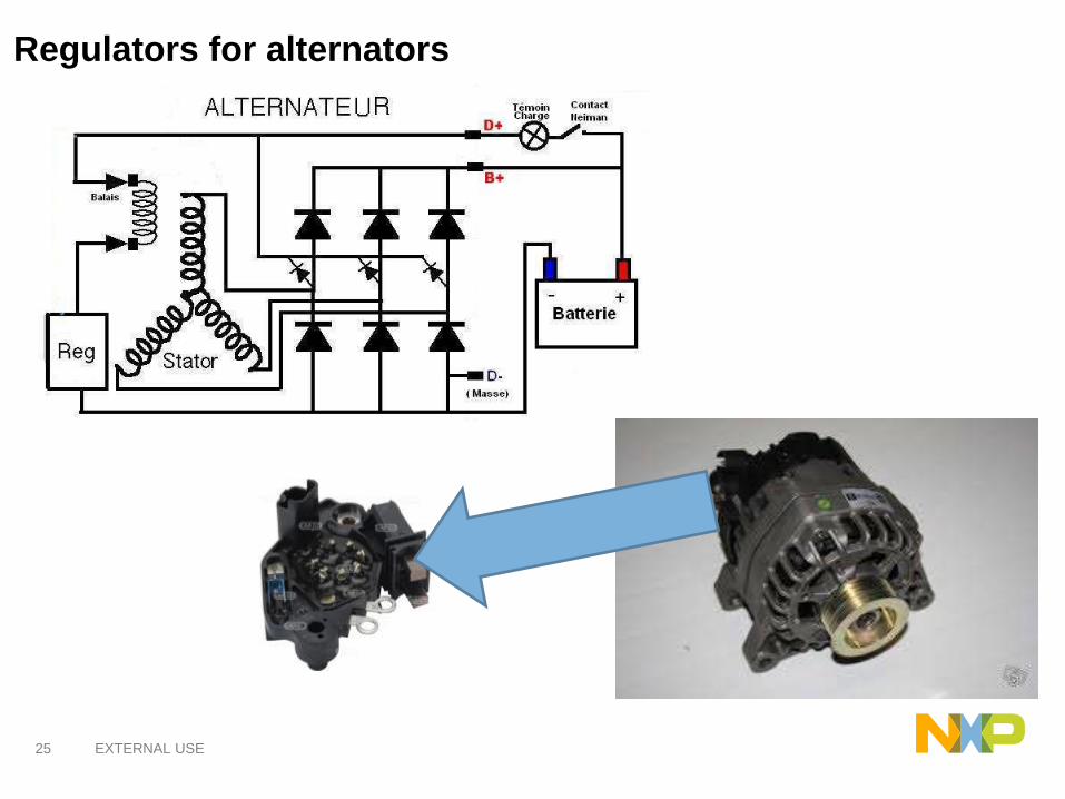
Regulators for alternators

26 EXTERNAL USE
Powertrain: Regulators for alternatorsKnown Good Die (KGD)
2. The dies are
tested (probed) by
NXP. Black plots
show bad dies
1. Wafer’s dies are
cut by NXP
3. The dies are
assembled on the
mechatronic
package by the
customer
27 EXTERNAL USE
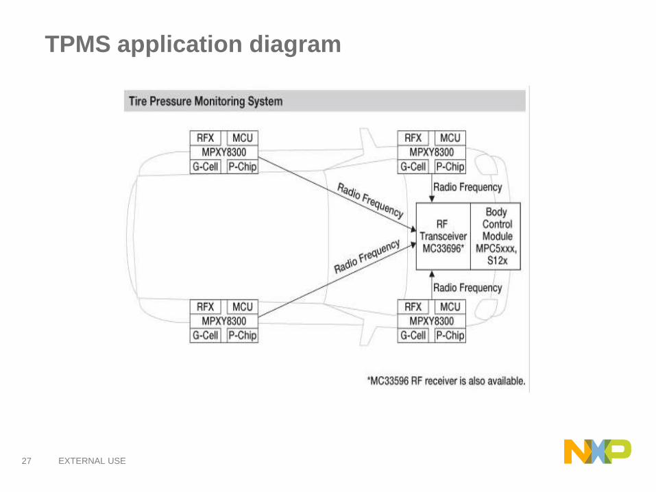
TPMS application diagram

28 EXTERNAL USE
Solutions for TPMS
Networking:• RF Transmitter
Microcontroller:• Control and Data
Conversion
Diverse Sensing:• Pressure
• 2-Axis MEMS
Accelerometer
29 EXTERNAL USE
Automotive Electronics : Agenda
1) Automotive electronics and semiconductor:
• Trends
• Specificities
• Technology
• Examples of application
• Functional Safety
2) Dissection of an automotive Microcontroler
• Core, Memories, Internal bus, Peripherals
• Dual-core, lock-step architecture
30 EXTERNAL USE
Automotive electronics : Functional safety
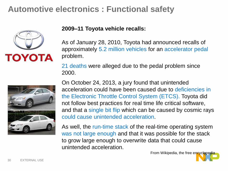
2009–11 Toyota vehicle recalls:
As of January 28, 2010, Toyota had announced recalls of
approximately 5.2 million vehicles for an accelerator pedal
problem.
21 deaths were alleged due to the pedal problem since
2000.
On October 24, 2013, a jury found that unintended
acceleration could have been caused due to deficiencies in
the Electronic Throttle Control System (ETCS). Toyota did
not follow best practices for real time life critical software,
and that a single bit flip which can be caused by cosmic rays
could cause unintended acceleration.
As well, the run-time stack of the real-time operating system
was not large enough and that it was possible for the stack
to grow large enough to overwrite data that could cause
unintended acceleration.From Wikipedia, the free encyclopedia

31 EXTERNAL USE
Source of High Energy Particles
primary cosmic particles (80% protons. 19% Alpha-particles) with
kinetic energy of 1 GeV -100 EeV (1020eV) collide with
atmosphere generating a shower of secondary particles at
terrestrial level.
Freescale, the Freescale logo, AltiVec, C-5, CodeTEST, CodeWarrior, ColdFire, ColdFire+, C-Ware, the Energy Efficient Solutions logo, Kinetis,
mobileGT, PowerQUICC, Processor Expert, QorIQ, Qorivva, StarCore, Symphony and VortiQa are trademarks of Freescale Semiconductor, Inc.,
Reg. U.S. Pat. & Tm. Off. Airfast, BeeKit, BeeStack, CoreNet, Flexis, Layerscape, MagniV, MXC, Platform in a Package, QorIQ Qonverge, QUICC
Engine, Ready Play, SafeAssure, the SafeAssure logo, SMARTMOS, TurboLink, Vybrid and Xtrinsic are trademarks of Freescale Semiconductor,
Inc. All other product or service names are the property of their respective owners. © 2012 Freescale Semiconductor, Inc.
33 EXTERNAL USE
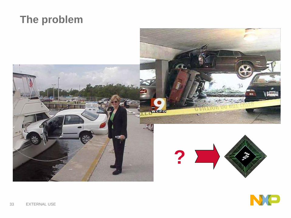
The problem
?
34 EXTERNAL USE
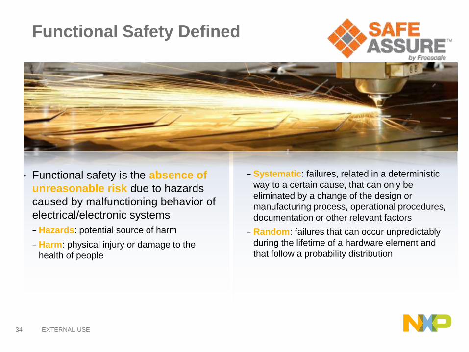
Functional Safety Defined
• Functional safety is the absence of
unreasonable risk due to hazards
caused by malfunctioning behavior of
electrical/electronic systems
− Hazards: potential source of harm
− Harm: physical injury or damage to the
health of people
− Systematic: failures, related in a deterministic
way to a certain cause, that can only be
eliminated by a change of the design or
manufacturing process, operational procedures,
documentation or other relevant factors
− Random: failures that can occur unpredictably
during the lifetime of a hardware element and
that follow a probability distribution
36 EXTERNAL USE
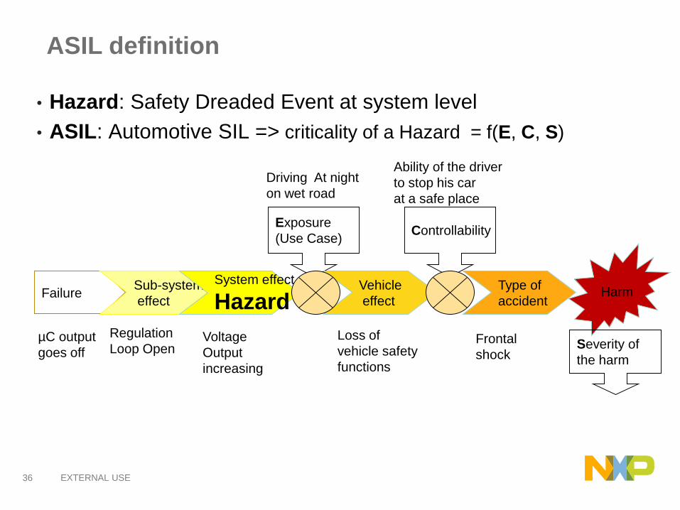
ASIL definition
• Hazard: Safety Dreaded Event at system level
• ASIL: Automotive SIL => criticality of a Hazard = f(E, C, S)
Failure
Exposure
(Use Case)
Sub-system
effect
System effect
HazardVehicle
effect
Controllability
Type of
accidentHarm
Severity of
the harm
µC output
goes off
Regulation
Loop OpenVoltage
Output
increasing
Driving At night
on wet road
Loss of
vehicle safety
functions
Ability of the driver
to stop his car
at a safe place
Frontal
shock
37 EXTERNAL USE
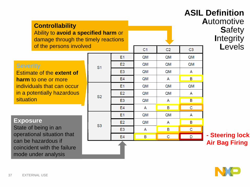
ASIL DefinitionAutomotive
SafetyIntegrity
Levels
SeverityEstimate of the extent of
harm to one or more
individuals that can occur
in a potentially hazardous
situation
ExposureState of being in an
operational situation that
can be hazardous if
coincident with the failure
mode under analysis
ControllabilityAbility to avoid a specified harm or
damage through the timely reactions
of the persons involved
- Steering lock
Air Bag Firing
38 EXTERNAL USE
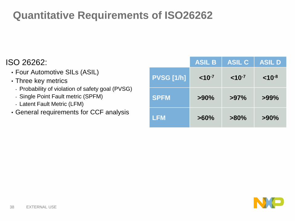
Quantitative Requirements of ISO26262
ISO 26262:• Four Automotive SILs (ASIL)
• Three key metrics
- Probability of violation of safety goal (PVSG)
- Single Point Fault metric (SPFM)
- Latent Fault Metric (LFM)
• General requirements for CCF analysis
ASIL B ASIL C ASIL D
PVSG [1/h] <10-7 <10-7 <10-8
SPFM >90% >97% >99%
LFM >60% >80% >90%
39 EXTERNAL USE
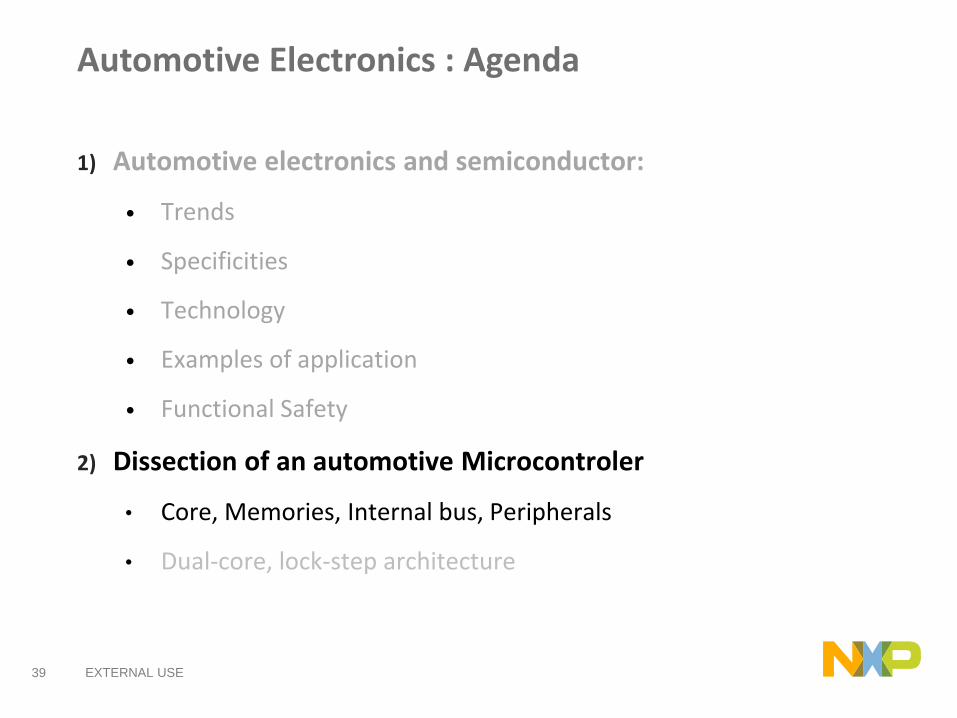
Automotive Electronics : Agenda
1) Automotive electronics and semiconductor:
• Trends
• Specificities
• Technology
• Examples of application
• Functional Safety
2) Dissection of an automotive Microcontroler
• Core, Memories, Internal bus, Peripherals
• Dual-core, lock-step architecture

40 EXTERNAL USE
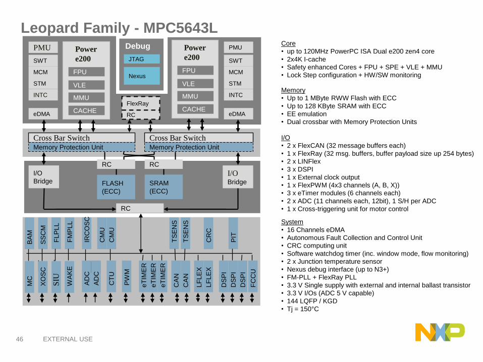
Leopard Family - MPC5643L
Cross Bar Switch
I/O
Bridge
BA
M
Memory Protection Unit
Cross Bar SwitchMemory Protection Unit
FlexRay
RC
RC RC
FLASH
(ECC)
SRAM
(ECC)
RC
I/OBridge
SS
CM
FLP
LL
FM
PLL
IRC
OS
C
CM
U
CM
U
CR
C
PIT
MC
XO
SC
SIU
WA
KE
TS
EN
S
TS
EN
S
AD
C
AD
C
CT
U
PW
M
eT
IME
R
eT
IME
R
eT
IME
R
CA
N
CA
N
LF
LE
X
LF
LE
X
DS
PI
DS
PI
DS
PI
FC
CU
PMU
SWT
MCM
STM
INTC
eDMACACHE
Power
e200
MMU
VLE
CACHE
FPUNexus
JTAG
Debug PMU
SWT
MCM
STM
INTC
eDMACACHE
Power
e200
MMU
VLE
CACHE
FPU
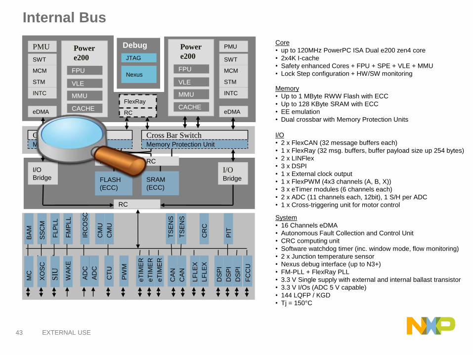
Core
• up to 120MHz PowerPC ISA Dual e200 zen4 core
• 2x4K I-cache
• Safety enhanced Cores + FPU + SPE + VLE + MMU
• Lock Step configuration + HW/SW monitoring
Memory
• Up to 1 MByte RWW Flash with ECC
• Up to 128 KByte SRAM with ECC
• EE emulation
• Dual crossbar with Memory Protection Units
I/O
• 2 x FlexCAN (32 message buffers each)
• 1 x FlexRay (32 msg. buffers, buffer payload size up 254 bytes)
• 2 x LINFlex
• 3 x DSPI
• 1 x External clock output
• 1 x FlexPWM (4x3 channels (A, B, X))
• 3 x eTimer modules (6 channels each)
• 2 x ADC (11 channels each, 12bit), 1 S/H per ADC
• 1 x Cross-triggering unit for motor control
System
• 16 Channels eDMA
• Autonomous Fault Collection and Control Unit
• CRC computing unit
• Software watchdog timer (inc. window mode, flow monitoring)
• 2 x Junction temperature sensor
• Nexus debug interface (up to N3+)
• FM-PLL + FlexRay PLL
• 3.3 V Single supply with external and internal ballast transistor
• 3.3 V I/Os (ADC 5 V capable)
• 144 LQFP / KGD
• Tj = 150°C
41 EXTERNAL USE
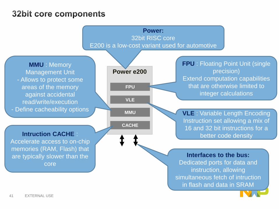
Power e200
MMU
VLE
CACHE
FPU
Power:
32bit RISC core
E200 is a low-cost variant used for automotive
FPU : Floating Point Unit (single
precision)
Extend computation capabilities
that are otherwise limited to
integer calculations
VLE : Variable Length Encoding
Instruction set allowing a mix of
16 and 32 bit instructions for a
better code density
MMU : Memory
Management Unit
- Allows to protect some
areas of the memory
against accidental
read/write/execution
- Define cacheability options
Intruction CACHE :
Accelerate access to on-chip
memories (RAM, Flash) that
are typically slower than the
core
Interfaces to the bus:
Dedicated ports for data and
instruction, allowing
simultaneous fetch of intruction
in flash and data in SRAM

42 EXTERNAL USE
Memories
Cross Bar Switch
I/O
Bridge
BA
M
Memory Protection Unit
Cross Bar SwitchMemory Protection Unit
FlexRay
RC
RC RC
FLASH
(ECC)
SRAM
(ECC)
RC
I/OBridge
SS
CM
FLP
LL
FM
PLL
IRC
OS
C
CM
U
CM
U
CR
C
PIT
MC
XO
SC
SIU
WA
KE
TS
EN
S
TS
EN
S
AD
C
AD
C
CT
U
PW
M
eT
IME
R
eT
IME
R
eT
IME
R
CA
N
CA
N
LF
LE
X
LF
LE
X
DS
PI
DS
PI
DS
PI
FC
CU
PMU
SWT
MCM
STM
INTC
eDMACACHE
Power
e200
MMU
VLE
CACHE
FPUNexus
JTAG
Debug PMU
SWT
MCM
STM
INTC
eDMACACHE
Power
e200
MMU
VLE
CACHE
FPU
Internal memories (Flash and
SRAM) are protected by ECC
(Error Correction Code).
These ECC allows to
automatically correct single
error, and detect double errors
43 EXTERNAL USE
Internal Bus
Cross Bar Switch
I/O
Bridge
BA
M
Memory Protection Unit
Cross Bar SwitchMemory Protection Unit
FlexRay
RC
RC RC
FLASH
(ECC)
SRAM
(ECC)
RC
I/OBridge
SS
CM
FLP
LL
FM
PLL
IRC
OS
C
CM
U
CM
U
CR
C
PIT
MC
XO
SC
SIU
WA
KE
TS
EN
S
TS
EN
S
AD
C
AD
C
CT
U
PW
M
eT
IME
R
eT
IME
R
eT
IME
R
CA
N
CA
N
LF
LE
X
LF
LE
X
DS
PI
DS
PI
DS
PI
FC
CU
PMU
SWT
MCM
STM
INTC
eDMACACHE
Power
e200
MMU
VLE
CACHE
FPUNexus
JTAG
Debug PMU
SWT
MCM
STM
INTC
eDMACACHE
Power
e200
MMU
VLE
CACHE
FPU
Core
• up to 120MHz PowerPC ISA Dual e200 zen4 core
• 2x4K I-cache
• Safety enhanced Cores + FPU + SPE + VLE + MMU
• Lock Step configuration + HW/SW monitoring
Memory
• Up to 1 MByte RWW Flash with ECC
• Up to 128 KByte SRAM with ECC
• EE emulation
• Dual crossbar with Memory Protection Units
I/O
• 2 x FlexCAN (32 message buffers each)
• 1 x FlexRay (32 msg. buffers, buffer payload size up 254 bytes)
• 2 x LINFlex
• 3 x DSPI
• 1 x External clock output
• 1 x FlexPWM (4x3 channels (A, B, X))
• 3 x eTimer modules (6 channels each)
• 2 x ADC (11 channels each, 12bit), 1 S/H per ADC
• 1 x Cross-triggering unit for motor control
System
• 16 Channels eDMA
• Autonomous Fault Collection and Control Unit
• CRC computing unit
• Software watchdog timer (inc. window mode, flow monitoring)
• 2 x Junction temperature sensor
• Nexus debug interface (up to N3+)
• FM-PLL + FlexRay PLL
• 3.3 V Single supply with external and internal ballast transistor
• 3.3 V I/Os (ADC 5 V capable)
• 144 LQFP / KGD
• Tj = 150°C
44 EXTERNAL USE
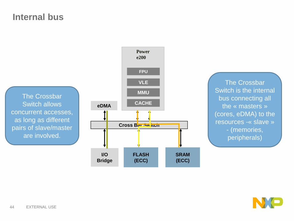
Internal bus
The Crossbar
Switch is the internal
bus connecting all
the « masters »
(cores, eDMA) to the
resources -« slave »
- (memories,
peripherals)
The Crossbar
Switch allows
concurrent accesses,
as long as different
pairs of slave/master
are involved.
Cross Bar Switch
I/O
Bridge
FLASH
(ECC)
SRAM
(ECC)
eDMACACHE
Power
e200
MMU
VLE
CACHE
FPU
45 EXTERNAL USE
Peripherals
Cross Bar Switch
I/O
Bridge
BA
M
Memory Protection Unit
Cross Bar SwitchMemory Protection Unit
FlexRay
RC
RC RC
FLASH
(ECC)
SRAM
(ECC)
RC
I/OBridge
SS
CM
FLP
LL
FM
PLL
IRC
OS
C
CM
U
CM
U
CR
C
PIT
MC
XO
SC
SIU
WA
KE
TS
EN
S
TS
EN
S
AD
C
AD
C
CT
U
PW
M
eT
IME
R
eT
IME
R
eT
IME
R
CA
N
CA
N
LF
LE
X
LF
LE
X
DS
PI
DS
PI
DS
PI
FC
CU
PMU
SWT
MCM
STM
INTC
eDMACACHE
Power
e200
MMU
VLE
CACHE
FPUNexus
JTAG
Debug PMU
SWT
MCM
STM
INTC
eDMACACHE
Power
e200
MMU
VLE
CACHE
FPU
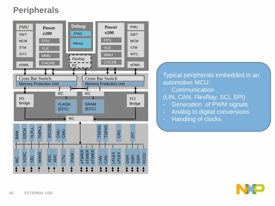
Typical peripherals embedded in an
automotive MCU:
- Communication
(LIN, CAN, FlexRay, SCI, SPI)
- Generation of PWM signals
- Analog to digital conversions
- Handling of clocks
46 EXTERNAL USE
Leopard Family - MPC5643L
Cross Bar Switch
I/O
Bridge
BA
M
Memory Protection Unit
Cross Bar SwitchMemory Protection Unit
FlexRay
RC
RC RC
FLASH
(ECC)
SRAM
(ECC)
RC
I/OBridge
SS
CM
FLP
LL
FM
PLL
IRC
OS
C
CM
U
CM
U
CR
C
PIT
MC
XO
SC
SIU
WA
KE
TS
EN
S
TS
EN
S
AD
C
AD
C
CT
U
PW
M
eT
IME
R
eT
IME
R
eT
IME
R
CA
N
CA
N
LF
LE
X
LF
LE
X
DS
PI
DS
PI
DS
PI
FC
CU
PMU
SWT
MCM
STM
INTC
eDMACACHE
Power
e200
MMU
VLE
CACHE
FPUNexus
JTAG
Debug PMU
SWT
MCM
STM
INTC
eDMACACHE
Power
e200
MMU
VLE
CACHE
FPU
Core
• up to 120MHz PowerPC ISA Dual e200 zen4 core
• 2x4K I-cache
• Safety enhanced Cores + FPU + SPE + VLE + MMU
• Lock Step configuration + HW/SW monitoring
Memory
• Up to 1 MByte RWW Flash with ECC
• Up to 128 KByte SRAM with ECC
• EE emulation
• Dual crossbar with Memory Protection Units
I/O
• 2 x FlexCAN (32 message buffers each)
• 1 x FlexRay (32 msg. buffers, buffer payload size up 254 bytes)
• 2 x LINFlex
• 3 x DSPI
• 1 x External clock output
• 1 x FlexPWM (4x3 channels (A, B, X))
• 3 x eTimer modules (6 channels each)
• 2 x ADC (11 channels each, 12bit), 1 S/H per ADC
• 1 x Cross-triggering unit for motor control
System
• 16 Channels eDMA
• Autonomous Fault Collection and Control Unit
• CRC computing unit
• Software watchdog timer (inc. window mode, flow monitoring)
• 2 x Junction temperature sensor
• Nexus debug interface (up to N3+)
• FM-PLL + FlexRay PLL
• 3.3 V Single supply with external and internal ballast transistor
• 3.3 V I/Os (ADC 5 V capable)
• 144 LQFP / KGD
• Tj = 150°C

47 EXTERNAL USE
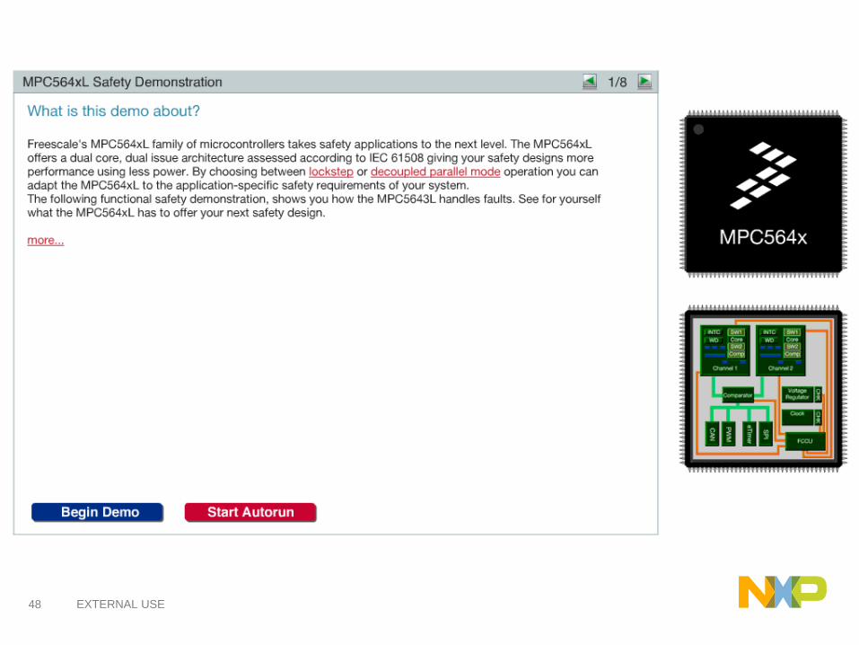
Dual Core Architecture: Modes of Operation
► 1x performance
► MCU mode which allows SIL3 with
minimal software overhead
► Formal check of outputs for replicated
IP modules
► Checker (RC) guarantee detection of
non-common cause faults when
redundant channels are merged
► 1.7x performance
► MCU mode which allows SIL3 with
algorithm diversity
► CPU cores and subsystems run
independently
► Checker units (RC) are disabled in this
mode
LSMLockStep Mode
DPMDecoupled Parallel Mode
▪ Device concept supports static configuration of the operating mode during Reset
▪ Selection between the two modes is done by programming a user option bit stored
in the shadow sector of the flash array
48 EXTERNAL USE

49 EXTERNAL USE
49

50 EXTERNAL USE
51 EXTERNAL USE
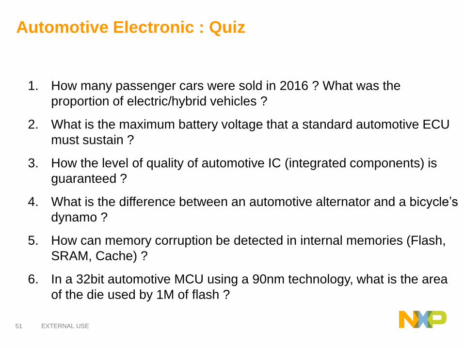
Automotive Electronic : Quiz
1. How many passenger cars were sold in 2016 ? What was the
proportion of electric/hybrid vehicles ?
2. What is the maximum battery voltage that a standard automotive ECU
must sustain ?
3. How the level of quality of automotive IC (integrated components) is
guaranteed ?
4. What is the difference between an automotive alternator and a bicycle’s
dynamo ?
5. How can memory corruption be detected in internal memories (Flash,
SRAM, Cache) ?
6. In a 32bit automotive MCU using a 90nm technology, what is the area
of the die used by 1M of flash ?

52 EXTERNAL USE
Code Correcteur d’erreur : exemple 1/3
Soit un bloc de 3 nombres que l’on souhaite stocker/transmettre.
23 15 12
A ce bloc de 3 nombres, on adjoint 2 nombres de contrôle:
• le premier est la somme des 3 nombres
23 + 15 + 12 = 50
• le deuxième est la somme pondérée des 3 nombres
23x1 + 15x2 + 12x3 = 89
Les 2 champs (données + contrôle) sont stockées en mémoire:
23 15 12 50 89
53 EXTERNAL USE
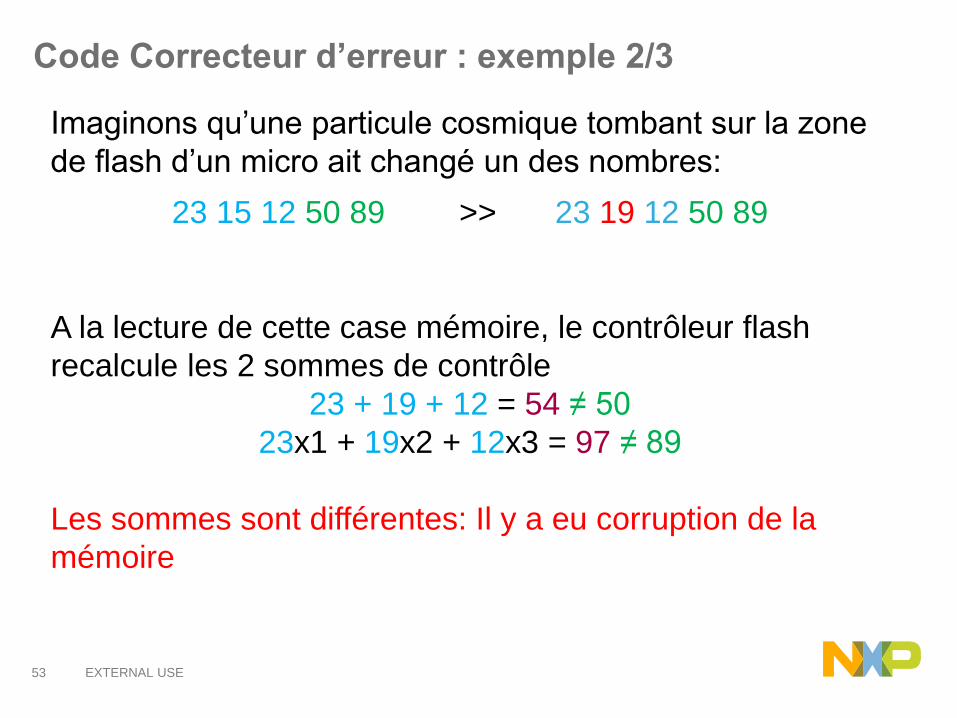
Code Correcteur d’erreur : exemple 2/3
Imaginons qu’une particule cosmique tombant sur la zone
de flash d’un micro ait changé un des nombres:
23 15 12 50 89 >> 23 19 12 50 89
A la lecture de cette case mémoire, le contrôleur flash
recalcule les 2 sommes de contrôle
23 + 19 + 12 = 54 ≠ 50
23x1 + 19x2 + 12x3 = 97 ≠ 89
Les sommes sont différentes: Il y a eu corruption de la
mémoire
54 EXTERNAL USE
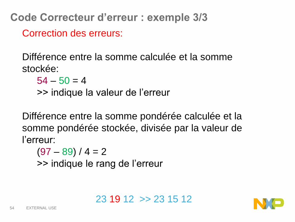
Correction des erreurs:
Différence entre la somme calculée et la somme
stockée:
54 – 50 = 4
>> indique la valeur de l’erreur
Différence entre la somme pondérée calculée et la
somme pondérée stockée, divisée par la valeur de
l’erreur:
(97 – 89) / 4 = 2
>> indique le rang de l’erreur
23 19 12 >> 23 15 12
Code Correcteur d’erreur : exemple 3/3

55 EXTERNAL USE
AUTOMOTIVE COMMUNICATION BUSES
1) Multiplexing: What does it bring ?
2) LIN protocol
3) CAN protocol
4) FlexRay protocol

56 EXTERNAL USE
Qu’est-ce que le multiplexage ? 1/2
Exemple d’un module de portes, incluant les
fonctions de réglage de rétroviseurs, de verrouillage
de portes et d’ouverture des fenêtres
Système non-multiplexé:
57 EXTERNAL USE
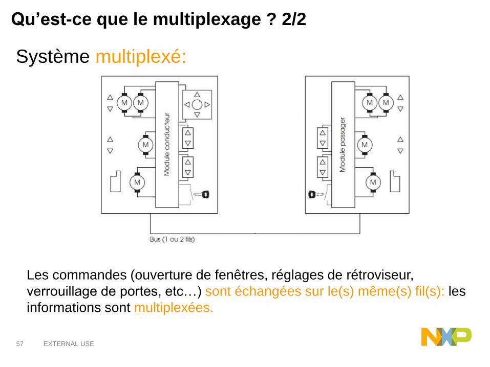
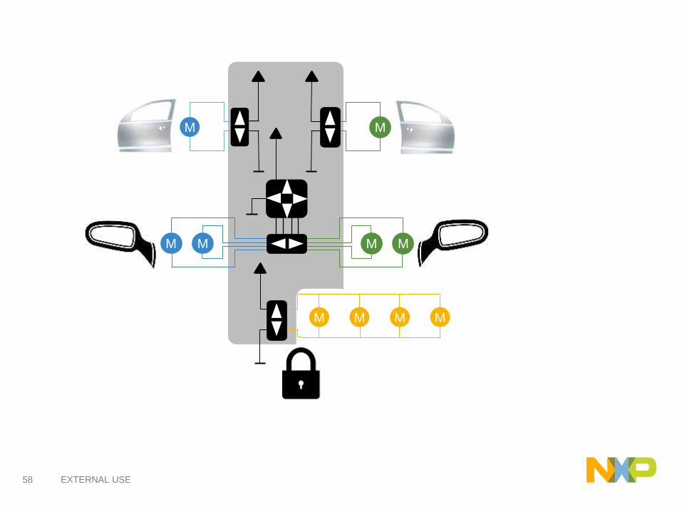
Système multiplexé:
Qu’est-ce que le multiplexage ? 2/2
Les commandes (ouverture de fenêtres, réglages de rétroviseur,
verrouillage de portes, etc…) sont échangées sur le(s) même(s) fil(s): les
informations sont multiplexées.
58 EXTERNAL USE
M M
M M
M M M M
MM
59 EXTERNAL USE
M
M M
M
M
MM
M
M
M
M
M
Communication

60 EXTERNAL USE
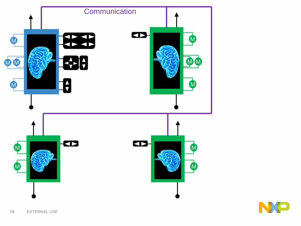
Pourquoi le multiplexage ?
Le multiplexage permet:
• de réduire le nombre de fils et de connecteurs entre les
unités de calcul
• de réduire le poids du véhicule
• d’implémenter un diagnostic centralisé
• d’implémenter des fonctions électroniques plus élaborées
Source PSA
61 EXTERNAL USE
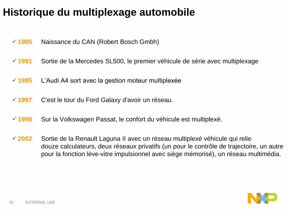
✓ 1985 Naissance du CAN (Robert Bosch Gmbh)
✓ 1991 Sortie de la Mercedes SL500, le premier véhicule de série avec multiplexage
✓ 1995 L’Audi A4 sort avec la gestion moteur multiplexée
✓ 1997 C'est le tour du Ford Galaxy d'avoir un réseau.
✓ 1998 Sur la Volkswagen Passat, le confort du véhicule est multiplexé.
✓ 2002 Sortie de la Renault Laguna II avec un réseau multiplexé véhicule qui relie
douze calculateurs, deux réseaux privatifs (un pour le contrôle de trajectoire, un autre
pour la fonction lève-vitre impulsionnel avec siège mémorisé), un réseau multimédia.
Historique du multiplexage automobile
62 EXTERNAL USE
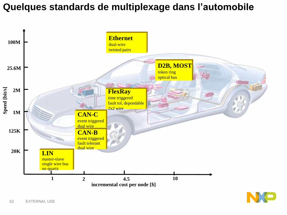
Quelques standards de multiplexage dans l’automobileS
pee
d [
bit
/s]
LINmaster-slavesingle wire busno quartz
CAN-Bevent triggeredfault tolerantdual wire
CAN-Cevent triggered
dual wire
FlexRaytime triggered
fault tol, dependable
2x2 wire
25.6M
20K
2M
1M
125K
incremental cost per node [$]
D2B, MOSTtoken ring
optical bus
1 2 4.5 10
100MEthernetdual-wire
twisted pairs
63 EXTERNAL USE
Le protocole LIN

64 EXTERNAL USE
In the late 1990s, the LIN Consortium was founded by five automakers
(BMW, Volkswagen Audi Group, Volvo Cars, Mercedes-Benz), with the
technologies supplied (networking and hardware expertise) from Volcano
Automotive Group and Motorola.
65 EXTERNAL USE
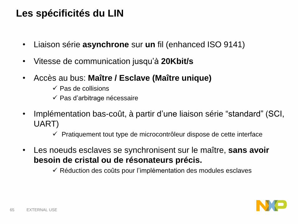
Les spécificités du LIN
• Liaison série asynchrone sur un fil (enhanced ISO 9141)
• Vitesse de communication jusqu’à 20Kbit/s
• Accès au bus: Maître / Esclave (Maître unique)
✓ Pas de collisions
✓ Pas d’arbitrage nécessaire
• Implémentation bas-coût, à partir d’une liaison série “standard” (SCI,
UART)
✓ Pratiquement tout type de microcontrôleur dispose de cette interface
• Les noeuds esclaves se synchronisent sur le maître, sans avoir
besoin de cristal ou de résonateurs précis.
✓ Réduction des coûts pour l’implémentation des modules esclaves
67 EXTERNAL USE
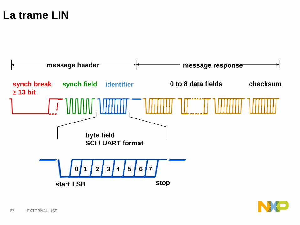
La trame LIN
0 to 8 data fields checksum
message response
synch break
13 bit
synch field identifier
message header
byte field
SCI / UART format
start stop
0 1 2 3 4 5 6 7
LSB
68 EXTERNAL USE
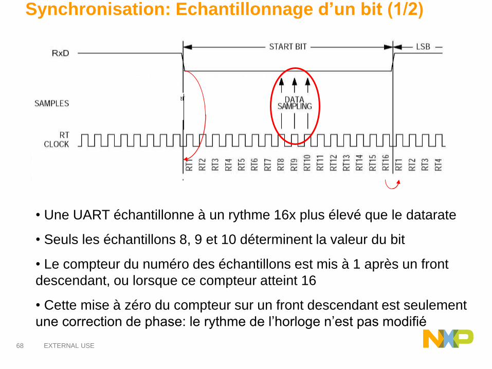
Synchronisation: Echantillonnage d’un bit (1/2)
• Une UART échantillonne à un rythme 16x plus élevé que le datarate
• Seuls les échantillons 8, 9 et 10 déterminent la valeur du bit
• Le compteur du numéro des échantillons est mis à 1 après un front
descendant, ou lorsque ce compteur atteint 16
• Cette mise à zéro du compteur sur un front descendant est seulement
une correction de phase: le rythme de l’horloge n’est pas modifié
69 EXTERNAL USE
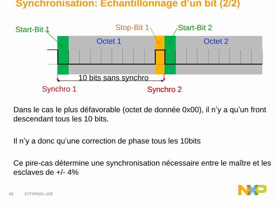
Synchronisation: Echantillonnage d’un bit (2/2)
Dans le cas le plus défavorable (octet de donnée 0x00), il n’y a qu’un front
descendant tous les 10 bits.
Il n’y a donc qu’une correction de phase tous les 10bits
Ce pire-cas détermine une synchronisation nécessaire entre le maître et les
esclaves de +/- 4%
Synchro 1
Stop-Bit 1Start-Bit 1
Octet 1 Octet 2
Start-Bit 2
Synchro 2
10 bits sans synchro
Synchro 2
70 EXTERNAL USE
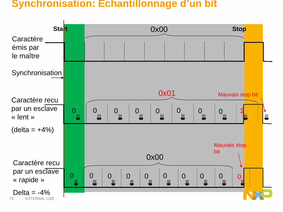
Synchronisation: Echantillonnage d’un bit
Start Stop
Caractère
émis par
le maître
Synchronisation
0x00
Caractère recu
par un esclave
« lent »
(delta = +4%)
Mauvais stop bit0x01
Mauvais stop
bit
Caractère recu
par un esclave
« rapide »
Delta = -4%
0x00
0 0 0 0 0 0 0 0 1
0 0 0 0 0 0 0 0 0 0
71 EXTERNAL USE
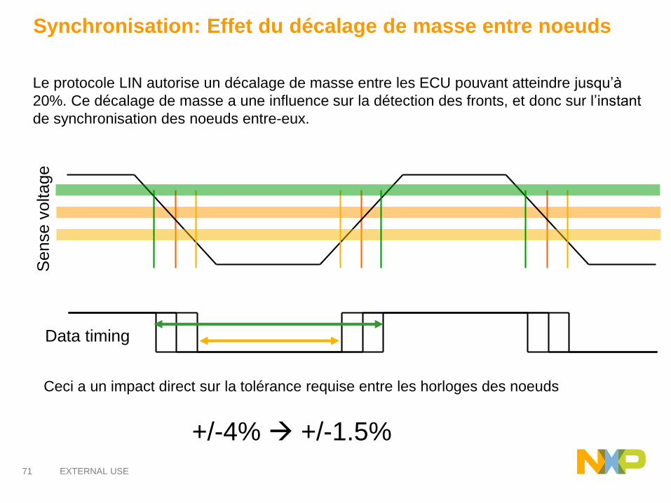
Synchronisation: Effet du décalage de masse entre noeuds
Le protocole LIN autorise un décalage de masse entre les ECU pouvant atteindre jusqu’à
20%. Ce décalage de masse a une influence sur la détection des fronts, et donc sur l’instant
de synchronisation des noeuds entre-eux.
Data timing
Sense v
oltage
Ceci a un impact direct sur la tolérance requise entre les horloges des noeuds
+/-4% +/-1.5%
72 EXTERNAL USE
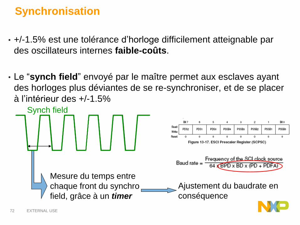
Synchronisation
• +/-1.5% est une tolérance d’horloge difficilement atteignable par
des oscillateurs internes faible-coûts.
• Le “synch field” envoyé par le maître permet aux esclaves ayant
des horloges plus déviantes de se re-synchroniser, et de se placer
à l’intérieur des +/-1.5%
Ajustement du baudrate en
conséquence
Mesure du temps entre
chaque front du synchro
field, grâce à un timer
Synch field
73 EXTERNAL USE
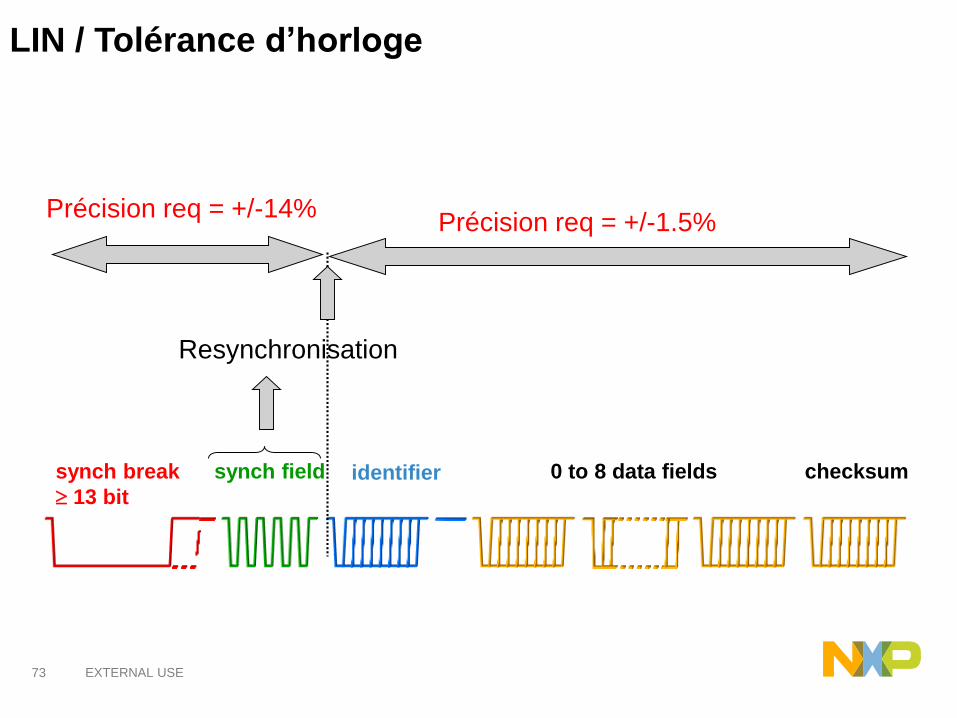
LIN / Tolérance d’horloge
0 to 8 data fields checksumsynch break
13 bit
synch field identifier
Précision req = +/-14%
Resynchronisation
Précision req = +/-1.5%
74 EXTERNAL USE
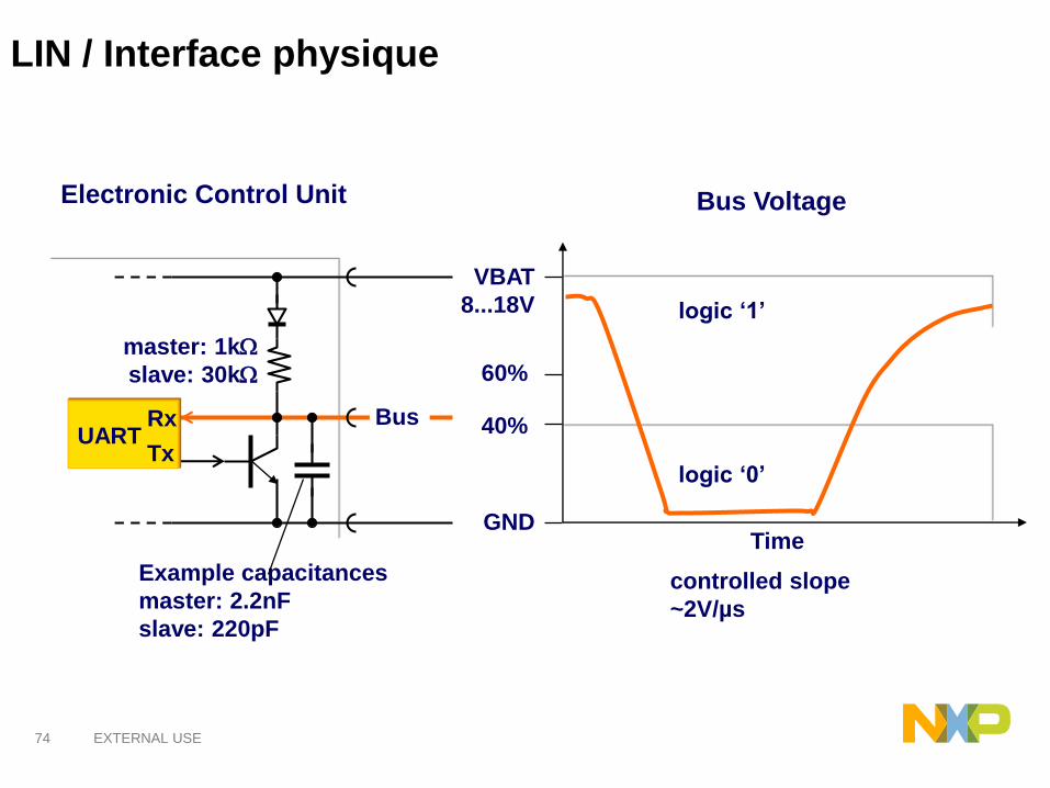
LIN / Interface physique
UARTRx
Tx
Electronic Control Unit
master: 1k
slave: 30k
Bus
Example capacitances
master: 2.2nF
slave: 220pF
VBAT
8...18V
GND
logic ‘1’
logic ‘0’
60%
40%
Bus Voltage
Time
controlled slope
~2V/µs

75 EXTERNAL USE
LIN: Quiz
1. Quelles « fautes » le protocole LIN supporte t-il ?
2. Que se passe t-il si l’ ECU maître ne fonctionne plus ?
3. Que se passe t-il si deux ECUs essaient d’emettre des niveaux
différents en même temps ?
76 EXTERNAL USE
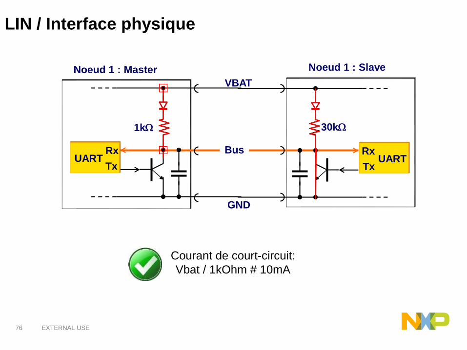
LIN / Interface physique
UARTRx
TxUART
Rx
Tx
Bus
VBAT
GND
1k 30k
Noeud 1 : Master Noeud 1 : Slave
Courant de court-circuit:
Vbat / 1kOhm # 10mA

77 EXTERNAL USE
Le protocole CAN

78 EXTERNAL USE
Development of Controller Area Network bus started originally in 1983
at Robert Bosch GmbH.[1]
The first CAN controller chips, produced by Intel and Philips, came on the
market in 1987. Bosch published the CAN 2.0 specification in 1991.
In 2012 Bosch has specified the improved CAN data link layer protocol, called
CAN FD, which will extend the ISO 11898-1.
Wolfhard LawrenzUwe Kiencke
79 EXTERNAL USE
Caractéristiques du bus CAN :
• Liaison série asynchrone sur deux fils
• Vitesse de communication jusqu’a 1Mbit/sec (500kbit/sec dans l’auto)
• Accés au bus CSMA (Carrier Sense Multiple Access) ✓Des collisions peuvent se produire, elles sont detectées et arbitrées
• Détection et signalisation d'erreurs par tous les noeuds du réseau
✓Distinction entre des erreurs temporaires et des non-fonctionnalités permanentesau niveau d'un noeud
✓Déconnexion automatique des noeuds défectueux
Généralités
80 EXTERNAL USE
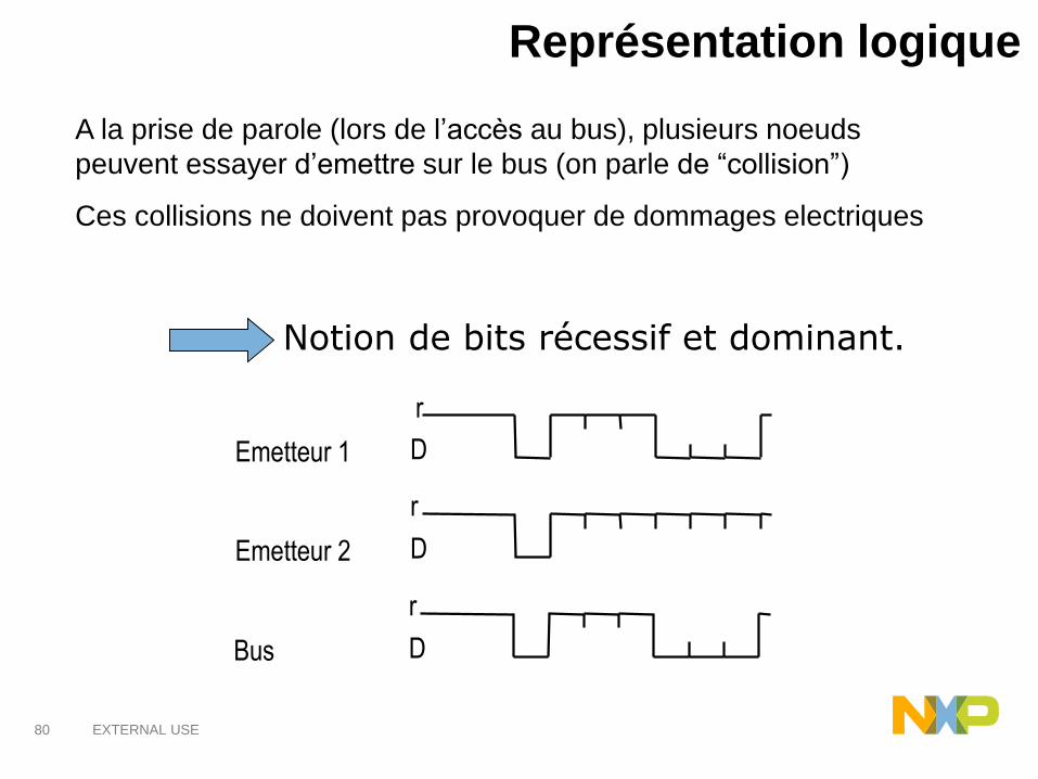
Représentation logique
A la prise de parole (lors de l’accès au bus), plusieurs noeuds
peuvent essayer d’emettre sur le bus (on parle de “collision”)
Ces collisions ne doivent pas provoquer de dommages electriques
Notion de bits récessif et dominant.
r
Emetteur 1
Emetteur 2
Bus
D
r
D
r
D

81 EXTERNAL USE
Si plusieurs trames sont émises en même temps:
1. Chaque noeud émet normalement et observe l’état du bus
2. L’état du bus est dicté par le caractère récessif ou dominant des bits émis
3. Un noeud émetteur observant sur le bus un état différent de celuiqu’il a émis, cesse l’émission et devient récepteur
Supposition: Noeuds synchronisés
CAN / Accès au bus: Arbitrage

82 EXTERNAL USE
Arbitrage -Exemple-
Bus Idle
SOF
Bus Idle
Bus Idle
Bus Idle
Emetteur 1
Emetteur 2
Emetteur 3
Etat du bus
Perte d’arbitrage
Plus d’emission
Perte d’arbitrage
Plus d’emission
Bit dominant
Bit recessif
83 EXTERNAL USE
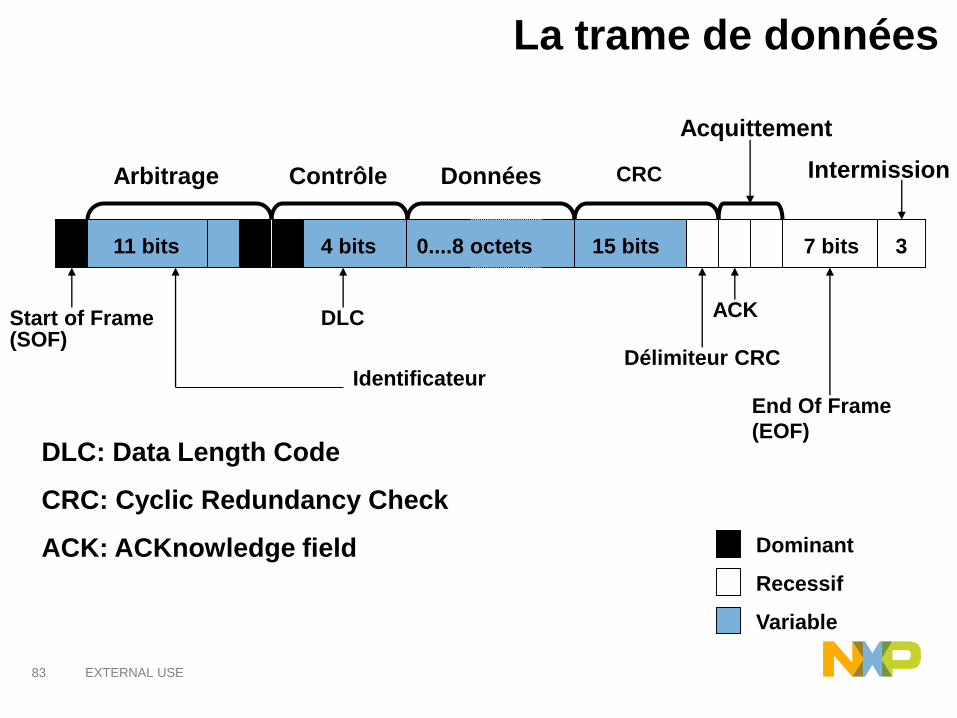
La trame de données
DLC: Data Length Code
CRC: Cyclic Redundancy Check
ACK: ACKnowledge field
Start of Frame(SOF)
11 bits
Arbitrage
4 bits
Contrôle Données
0....8 octets
DLC
15 bits
CRC
Délimiteur CRC
Acquittement
ACK
7 bits
End Of Frame
(EOF)
3
Intermission
Identificateur
Recessif
Dominant
Variable

84 EXTERNAL USE
Contient 2 bits:
➢Le second est toujours récessif
➢L’emetteur du message envoie le premier dans l’état
récessif
➢Un récepteur ayant reçu le message avec succés, met ce
bit dans l’état dominant (acquittement)
Champ d’acquittement

85 EXTERNAL USE
Bit stuffing: Exemple
Séquence à
émettre
Séquence
émise
Séquence
traitée en
réception
s s
86 EXTERNAL USE
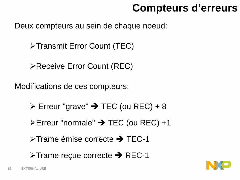
Compteurs d’erreurs
Deux compteurs au sein de chaque noeud:
➢Transmit Error Count (TEC)
➢Receive Error Count (REC)
Modifications de ces compteurs:
➢ Erreur "grave" TEC (ou REC) + 8
➢Erreur "normale" TEC (ou REC) +1
➢Trame émise correcte TEC-1
➢Trame reçue correcte REC-1
87 EXTERNAL USE
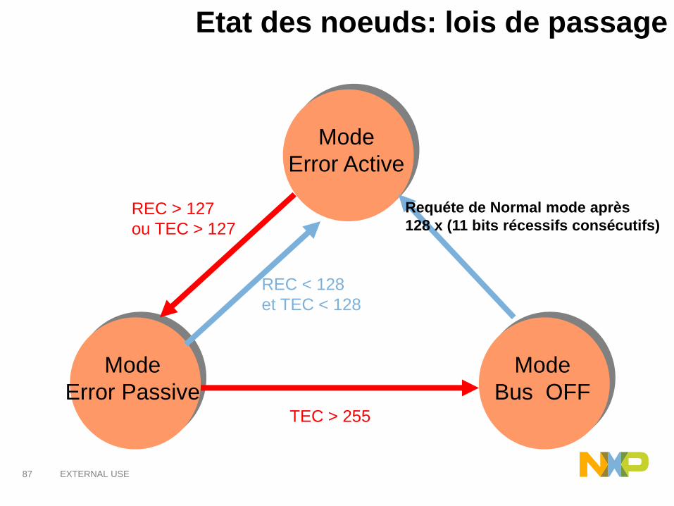
Etat des noeuds: lois de passage
Mode
Error Active
Mode
Bus OFF
Mode
Error Passive
REC < 128
et TEC < 128
REC > 127
ou TEC > 127
Requéte de Normal mode après
128 x (11 bits récessifs consécutifs)
TEC > 255

88 EXTERNAL USE
Trames d’erreur
• 2 TYPES DE TRAMES D'ERREURS :
− ACTIVE (Module en “error active”)
− PASSIVE (Module en “error passive”)
• FORMAT:
− ERROR FLAG: 6 bits dominants (active) ou récessifs (passive)
− ERROR DELIMITER: 8 bits récessifs
− entre ces deux champs, superposition des Flags des autres stations
Error Flag (6 bits)
Superposition des Error Flags(entre 6 et 12 bits)
Error Delimiter (8 bits)
89 EXTERNAL USE
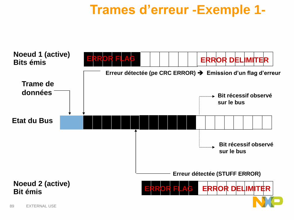
Trames d’erreur -Exemple 1-
ERROR FLAG
Erreur détectée (pe CRC ERROR) Emission d’un flag d’erreur
Etat du Bus
Noeud 2 (active)Bit émis
Noeud 1 (active)Bits émis
ERROR FLAG
ERROR DELIMITER
ERROR DELIMITER
Erreur détectée (STUFF ERROR)
Bit récessif observé
sur le bus
Bit récessif observé
sur le bus
Trame de
données
90 EXTERNAL USE
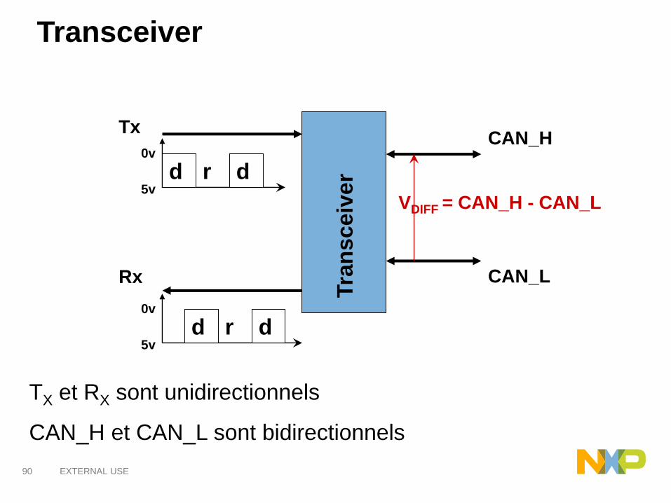
Transceiver
Tx
Rx
d r d0v
5v
d r d0v
5vTra
nsceiv
er
CAN_H
CAN_L
VDIFF = CAN_H - CAN_L
TX et RX sont unidirectionnels
CAN_H et CAN_L sont bidirectionnels

91 EXTERNAL USE
Transceiver
125 kbits/sec 1 Mbits/sec
HIGH SPEED TRANSCEIVERSFAULT TOLERANT TRANSCEIVERS
3.5V
2.5V
1.5V
Dominant Récessif
VDIFF = 2V VDIFF = 0V
3.6V
2.5V
1.4V
Dominant Récessif
VDIFF = 2.2V VDIFF = - 5V
0V
5V
CAN_HIGH
CAN_LOW

92 EXTERNAL USE
CAN: Quiz
1. Que se passe t-il si une ECU cesse de fonctionner (coupure
d’alimentation par exemple) ?
2. Que se passe t-il si une ECU envoie très fréquemment des trames
CAN de haute priorité ?
3. Si une ECU cherche à émettre un message au temps T, au bout de
combien de temps ∆T le message sera effectivement transmis sur le
bus ?

93 EXTERNAL USE
Le protocole FlexRay
94 EXTERNAL USE
FlexRay is an automotive network communications protocol developed
by the FlexRay Consortium to govern on-board automotive computing.
It is designed to be faster and more reliable than CAN and TTP, but it is
also more expensive.
The FlexRay Consortium was made up of the following core members:
Freescale Semiconductor
Robert Bosch GmbH
NXP Semiconductors
BMW AG
Volkswagen AG
Daimler AG
General Motors
There were also Premium Associate and Associate members of
FlexRay consortium. By September 2009, there were 28 premium
associate members and more than 60 associate members.

95 EXTERNAL USE
Le bus CAN présente quelques défauts:
• Débit limité à 1Mbit/s théorique mais 500kbit/sec en pratique
• Bus non déterministe: selon la charge du bus, certaines trames peu
prioritaires peuvent être bloquées, ou retardées. Il n’est pas possible de
garantir l’instant d’émission d’un message
• Failles de sécurité:
✓Une simple erreur sur un noeud peut empecher toute communication
(“babling idiot”: un noeud envoie sans arrêt des messages prioritaires)
✓Interface physique unique
Motivation du bus FlexRay
96 EXTERNAL USE
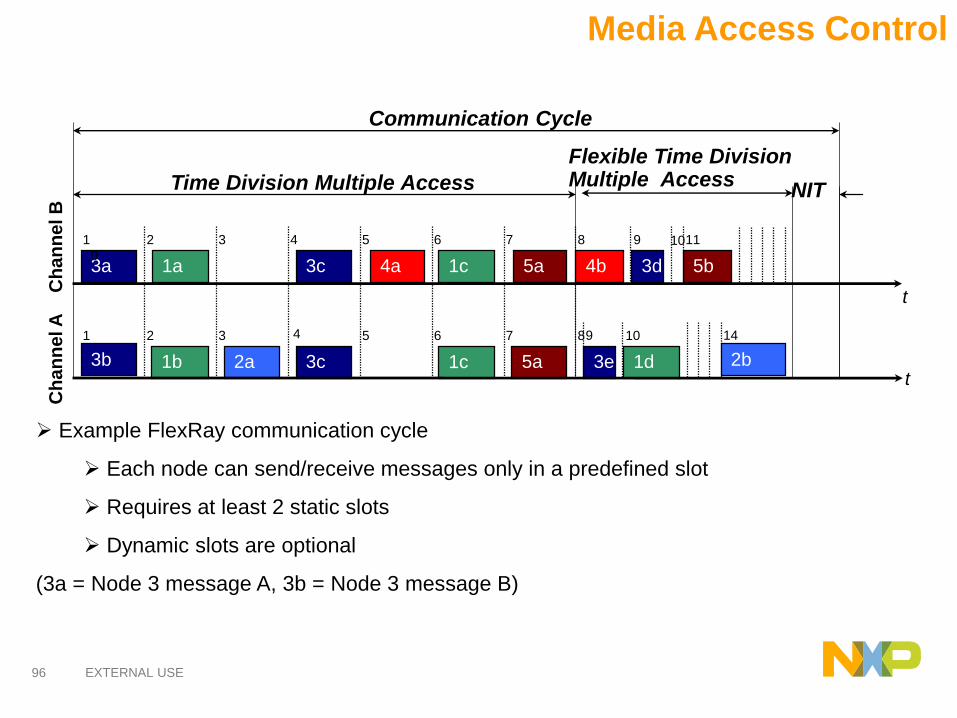
Media Access Control
Time Division Multiple Access
5b
1d
3d
3e
4b5a
5a
1c
1c
3c
3c2a
1a
1b
Ch
an
ne
l B
Ch
an
ne
l A
4a
Communication Cycle
t
t
2
2
3
3
4
4
5
5
6
6
7
7
8
89
9
10
11
3a
Flexible Time DivisionMultiple Access
NIT
1
0
1
3b 2b
10
14
➢ Example FlexRay communication cycle
➢ Each node can send/receive messages only in a predefined slot
➢ Requires at least 2 static slots
➢ Dynamic slots are optional
(3a = Node 3 message A, 3b = Node 3 message B)
97 EXTERNAL USE
Flexray: avantages et cibles
• Le bus FlexRay est déterministe dans sa partie statique: l’instant
d’envoi d’un message est sous contrôle et prédictible.
• FlexRay a d’abord été conçu pour les applications dites « Safety
critical »:
• Electrical Power Steering
• Steering angle sensors
•X-by-Wire applications
• etc…