nx cam 9.0.2: cut region control for flowcut …...answers for industry. siemens plm software nx cam...
TRANSCRIPT

Answers for industry.
Siemens PLM Software
NX CAM 9.0.2:
Cut Region Control for Flowcut
Reference Tool Managing Cut Regions in Flowcut Reference Tool Operations.

2
About NX CAM
NXTM CAM software has helped many of the world’s leading manufacturers and job shops produce better
parts faster. You can also achieve similar benefits by making use of the unique advantages NX CAM
offers.
This is one of many hands-on demonstrations designed to introduce you to the powerful capabilities in
NX CAM 9.0.2. In order to run this demonstration, you will need access to NX CAM 9.0.2.
Visit the NX Manufacturing Forum to learn more, ask questions, and share comments about NX CAM.

3
Hands-on Demonstration: Cut Region Control for Flowcut Reference Tool
The Cut Regions dialog box replaces the Manual Assembly dialog box for Flowcut Single, Flowcut
Multiple, and Flowcut Reference Tool operations. This new dialog box is easier to use and more
consistent with current NX user interface design. The ability to drag and drop makes reordering regions
much easier. Dividing regions is simpler and easier to control. You may resequence the cut order, merge
cut regions, and edit the containment type.
The graphics display has also been improved.
Do you have a question?
Post your questions or comments at the bottom of this Tech Tip article in the NX Manufacturing Forum.

4
Prerequisites:
1. You will need access to NX CAM 9.0.2 in order to run this demonstration.
2. If you haven’t done so already, download and unzip Cut Region Control for Flowcut Reference
Tool.7z. You will find the .7z file attached directly to this Tech Tip article in the NX Manufacturing
Forum.
Demo:
1. Open cut_regions.prt in NX.
2. In the Program Order View of the Operation Navigator, double-click FLOWCUT_REF_TOOL to
edit the operation.
3. In the Drive Method section of the dialog box, click Edit.
4. In the Output section of the dialog box, select User Defined from the Cut Order list.
5. Click OK.
6. Click Generate.

5
The Cut Regions dialog box is entirely new for Flowcut Reference Tool operations. For Flowcut
Single and Flowcut Multiple operations, the following five enhancements have been added to the
current Cut Regions dialog box:
1. Containment column
2. Type column
3. Merge button
4. Edit button
5. Resequence Cut Order button
Graphic on-screen displays are also new. They allow you to quickly associate the graphically
displayed cut regions with the cut order number.

6
Reordering regions The Cut Order column automatically updates when regions are reordered, eliminating the need to
renumber. Initially, the number sequence in the region name corresponds to the number sequence in
the Cut Order column.
7. Drag and drop FLOWCUT_REF_TOOL_R_5 below FLOWCUT_REF_TOOL_R_3.
Notice that FLOWCUT_REF_TOOL_R_5 is now #4 in the Cut Order column.
Resequencing the Cut Order
When the Cut Order column does not coincide with the top-to-bottom order of the cut regions, the
Cut Order column can be resequenced. This is particularly useful if you wish to cut steep or non-
steep regions first.
8. Click the Containment column heading several times and notice that all steep and non-steep
regions are gathered together and displayed first or last in the list.

7
9. Click the Containment column heading so that the steep cut regions are listed first.
Notice that the numbers listed in the Cut Order column do not coincide with the top-to-bottom order
of the listed regions.
10. Click Resequence Cut Order.
11. The numbers in the Cut Order column are resequenced to match the top-to-bottom order of the
listed cut regions. The steep regions are cut before the non-steep regions.
Editing the containment type Editing the containment type allows you to specify steep or non-steep for individually selected
regions.

8
12. Select FLOWCUT_REF_TOOL_R_11 from the Operation Regions list.
13. Click Edit .
14. Select Steep from the Containment Type list.
15. Click OK.
FLOWCUT_REF_TOOL_R_11 is now classified as a steep cut region and is listed with the steep
containment regions. FLOWCUT_REF_TOOL_R_11 is still number 15 in the cut order.
The cut order needs to be resequenced.
16. Click Resequence Cut Order .
FLOWCUT_REF_TOOL_R_11 is now number 13 in the cut order.
17. Click OK in the Cut Regions dialog box.

9
Non-steep areas (1) use a Zig Zag cut pattern and steep areas (2) use a Crosscut Zig cut
pattern.
Mixed cut regions ZLevel cut patterns create Area cut regions. This occurs because Flow regions do not use ZLevel cut
patterns. When a ZLevel cut pattern is specified for either steep or non-steep cutting, a mixture of
Flow and Area cut region types can result.
18. In the Drive Method section of the dialog box, click Edit.
19. Select ZLevel Zig from the Steep Cut Pattern list.

10
20. Click OK.
21. Click Generate.
22. Click OK in the Path Generation dialog box to confirm that cut regions will be recreated.
The Type column lists Area regions for steep containment and Flow regions for non-steep containment.
23. Select any region in the list.
The Edit option is not available when regions are mixed (recall that Edit allows you to
change the steep or non-steep containment for individually selected regions when regions are all
Flow).
The system does not allow you to edit the region containment because the Area regions in this
operation correspond to steep containment and the Flow regions correspond to non-steep
containment. Editing the region containment would require the system to change the region type.
Flow regions, which only apply to corners (bi-tangencies), cannot become Area regions.
Dividing regions The Divide option is easier to use than the previous Split option and is more consistent with standard
NX user interface design.
24. Select FLOWCUT_REF_TOOL_R_10 from the Operation Regions list. This is a Flow region.
25. Click Divide .
Flow regions are divided by picking a point. All node points for the region are displayed, making it
easy to determine where to pick.

11
26. Select near the node point where you wish to divide the region.
Note: Graphic on-screen displays can sometimes clutter the window. You can press F3 once to remove them from the display, twice to remove the dialog box, and three times to bring everything back.
You may divide only one cut region at a time.
27. Click OK in the Divide Region dialog box.
The region is divided into two Flow regions, each containing the name of the original but with an
additional number appended. The cut order is updated.
Area regions are divided by specifying a line or a plane.
28. Select FLOWCUT_REF_TOOL_R_16 from the Operation Regions list. This is an Area region.
29. Click Divide .
30. Select Plane from the Divide Option list.
31. Select Through Object from the Specify Plane list.

12
32. Select the edge of the body indicated below as the object for the plan to pass through.
33. Click OK in the Divide Region dialog box.
The divided region is indicated in the list by two Area regions.
Merge Cut Regions Merging allows you to combine two regions with adjacent edges.
The two regions you will merge are FLOWCUT_REF_TOOL_R_12 and
FLOWCUT_REF_TOOL_R_13. One is a Flow region and the other is an Area region.
34. Select each one in the Operation Regions list to see that they are adjacent.

13
Notice that these are two different types of cut regions.
35. Select FLOWCUT_REF_TOOL_R_12 in the Operation Regions list.
36. Click Merge .
FLOWCUT_REF_TOOL_R_12 is specified as the target region.
37. Select FLOWCUT_REF_TOOL_R_13 in the graphics display as the tool region.
38. Click OK in the Merge Regions dialog box.
The two regions merge into a single Area region using the name FLOWCUT_REF_TOOL_R_12.
Note: The target region determines the resulting region type and the name of the merged region.
When merging regions of different types, the target region must be an Area region. Area regions are
less restrictive than Flow regions; therefore a Flow region can become an Area region when merged.
Because Flow regions only apply to corners (bi-tangencies), Area regions cannot become Flow
regions.
39. Click Undo .
14
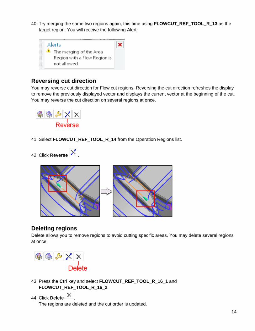
40. Try merging the same two regions again, this time using FLOWCUT_REF_TOOL_R_13 as the
target region. You will receive the following Alert:
Reversing cut direction You may reverse cut direction for Flow cut regions. Reversing the cut direction refreshes the display
to remove the previously displayed vector and displays the current vector at the beginning of the cut.
You may reverse the cut direction on several regions at once.
41. Select FLOWCUT_REF_TOOL_R_14 from the Operation Regions list.
42. Click Reverse .
Deleting regions Delete allows you to remove regions to avoid cutting specific areas. You may delete several regions
at once.
43. Press the Ctrl key and select FLOWCUT_REF_TOOL_R_16_1 and
FLOWCUT_REF_TOOL_R_16_2.
44. Click Delete .
The regions are deleted and the cut order is updated.

15
Undo Undo applies to reordering, dividing, merging, editing containment type, reversing, and deleting. It
may be used to undo, in reverse order, all cut region edits performed while in the currently displayed
Cut Regions dialog box.
45. Click Undo to undo the delete.
Preview
Preview determines whether or not cut direction vectors display. When many regions are selected, it
might become necessary to turn this option off to prevent screen clutter.
Right-clicking in the list You may right-click in any of the labeled columns to Divide, Merge, Edit, Reverse, or Delete.
Note: Edit does not display when regions are mixed and Reverse does not display when right-
clicking on Area regions.
46. Click OK in the Cut Regions dialog box to complete the cut regions edit.
47. Click OK to finish editing the operation.
48. In the Operation Navigator, right-click FLOWCUT_REF_TOOL and select Generate to generate
the tool path.
Edits are not lost when tool paths are re-generated in the operation dialog box or from the
Operation Navigator.
49. Continue practicing with the three operations in this part.
50. Close the part without saving when you have finished.

16
About Siemens PLM Software Siemens PLM Software, a business unit of the Siemens Industry Automation Division, is a leading global provider of product lifecycle management (PLM) software and services with seven million licensed seats and more than 71,000 customers worldwide. Headquartered in Plano, Texas, Siemens PLM Software works collaboratively with companies to deliver open solutions that help them turn more ideas into successful products. For more information on Siemens PLM Software products and services, visit www.siemens.com/plm.
© 2013 Siemens Product Lifecycle Management Software Inc. Siemens and the Siemens logo are registered trademarks of Siemens AG. D-Cubed, Femap, Geolus, GO PLM, I-deas, Insight, JT, NX, Parasolid, Solid Edge, Teamcenter, Tecnomatix and Velocity Series are trademarks or registered trademarks of Siemens Product Lifecycle Management Software Inc. or its subsidiaries in the United States and in other countries. All other logos, trademarks, registered trademarks or service marks used herein are the property of their respective holders. 8/13
www.siemens.com/plm/nxmanufacturingforum
Siemens Industry Software
Headquarters Granite Park One 5800 Granite Parkway Suite 600 Plano, TX 75024 USA +1 972 987 3000
Americas Granite Park One 5800 Granite Parkway Suite 600 Plano, TX 75024 USA +1 314 264 8499
Europe Stephenson House Sir William Siemens Square Frimley, Camberley Surrey, GU16 8QD +44 (0) 1276 413200
Asia-Pacific Suites 4301-4302, 43/F AIA Kowloon Tower, Landmark East 100 How Ming Street Kwun Tong, Kowloon Hong Kong +852 2230 3308