nvr/dvr/hybrid ndvr user manual - ov solutions, inc · nvr/dvr/hybrid ndvr . user manual . ......
TRANSCRIPT
NVR/DVR/Hybrid NDVR
User Manual
Ver. 11.350. A112.001
NVR/DVR/Hybrid NDVR System
- 1 -
TABLE OF CONTENTS
TABLE OF CONTENTS ........................................................................................................................ 1 INSTALLATION .................................................................................................................................... 7
Remote Desktop Tool .............................................................................................................................................. 11 DVR Driver Installation ............................................................................................................................................. 13 PDA Client Installation ............................................................................................................................................. 14 Smart Phone Client Installation ............................................................................................................................. 14
Quick Start ....................................................................................................................................... 15 Execute Main Console ............................................................................................................................................ 15 Activate IP Camera License(s) .............................................................................................................................. 15 Install IP camera(s) ................................................................................................................................................... 16 Add IP camera(s) ..................................................................................................................................................... 16 Set Schedule ............................................................................................................................................................. 18 Set Smart Guard ....................................................................................................................................................... 18 Start Recording & Smart Guard ............................................................................................................................ 19 Playback .................................................................................................................................................................... 20
1. MAIN CONSOLE .......................................................................................................................... 22 1.1 User Interface Overview ................................................................................................................................... 23 1.2 PTZ Camera Control .......................................................................................................................................... 27
1.2.1 Set Preset Point / Go to Preset Point....................................................................................................... 27 1.2.2 Zoom ............................................................................................................................................................. 28 1.2.3 Focus ............................................................................................................................................................ 28 1.2.4 Patrol ............................................................................................................................................................ 28
1.3 On Screen Menu ................................................................................................................................................ 29 1.3.1 Camera Setting .......................................................................................................................................... 29 1.3.2 Enable Move/Area Zoom ......................................................................... Error! Bookmark not defined. 1.3.3 Enable Talk .................................................................................................................................................. 29 1.3.4 Enable Digital PTZ ....................................................................................................................................... 29 1.3.5 ImmerVision Lens Setting .......................................................................... Error! Bookmark not defined. 1.3.6 Connect/ Disconnect ............................................................................................................................... 29 1.3.7 Show Camera ............................................................................................................................................. 29 1.3.8 Duplicate Camera..................................................................................................................................... 29 1.3.9 Delete Camera .......................................................................................................................................... 29 1.3.10 Enable Digital PTZ ..................................................................................................................................... 30 1.3.11 Fix Aspect Ratio ........................................................................................................................................ 30 1.3.12 Instant Playback ....................................................................................................................................... 30 1.3.13 Snapshot .................................................................................................................................................... 30 1.3.14 Manual Record ........................................................................................................................................ 30 1.3.15 Toggle Full screen .................................................................................................................................... 30 1.3.16 TV-Out Pop-up .......................................................................................................................................... 30
1.4 Live Display .......................................................................................................................................................... 30 1.5 Instant Playback ................................................................................................................................................ 31
1.5.1 Instant Playback window overview........................................................................................................ 31 1.5.2 The navigation of Instant Playback ........................................................................................................ 32
2. PLAYBACK ................................................................................................................................... 34 2.1 User Interface overview: ................................................................................................................................... 35 2.2 Open Record / Date Time Search Dialog .................................................................................................... 36
2.2.1 Date Time Panel ......................................................................................................................................... 36 2.2.2 Record Display Window............................................................................ Error! Bookmark not defined. 2.2.3 Date Time Period ........................................................................................................................................ 36 2.2.4 Video Preview ............................................................................................................................................. 36 2.2.5 Event Type ................................................................................................................................................... 36 2.2.6 Time Table .................................................................................................................................................... 36 2.2.7 Withdraw the Record ................................................................................................................................ 37
NVR/DVR/Hybrid NDVR System
- 2 -
2.3 Search Mode ...................................................................................................................................................... 38 2.3.1 Unusual Event-General Motion ............................................................................................................... 38 2.3.2 Unusual Event-Foreign Object ................................................................................................................. 38 2.3.3 Unusual Event-Missing Object .................................................................................................................. 38 2.3.4 Unusual Event- Focus Lost / Camera Occlusion .................................................................................. 39
2.4 Enhancement / Post Processing Tool ............................................................................................................. 39 2.4.1 General Setting .......................................................................................................................................... 39 2.4.2 Filter Setting ................................................................................................................................................. 39
2.5 Save Video .......................................................................................................................................................... 40 2.6 Save Image ......................................................................................................................................................... 41 2.7 Print ....................................................................................................................................................................... 41 2.8 Backup ................................................................................................................................................................. 42 2.9 Log Viewer .......................................................................................................................................................... 43
2.9.1 Unusual Event.............................................................................................................................................. 43 2.9.2 Export and Backup Log ............................................................................................................................ 43 2.9.3 System Log .................................................................................................................................................. 44 2.9.4 Counting Application................................................................................................................................ 45 2.9.5 Counting Application (Diagram) ............................................................................................................ 46 2.9.6 Metadata Log ............................................................................................................................................ 46 2.9.7 Export and Backup Log ............................................................................................................................ 47 2.9.8 Export ............................................................................................................................................................ 47
2.10 Setting ................................................................................................................................................................ 48 2.11 Remote Server .................................................................................................................................................. 50
2.11.1 Add Remote Playback Site .................................................................................................................... 50 2.11.2 Access Remote Playback Site ............................................................................................................... 50
3. SCHEDULE .................................................................................................................................... 51 3.1 Day / week Mode ............................................................................................................................................. 52
3.1.1 Load Preset Modes .................................................................................................................................... 52 3.1.2 Insert a New Schedule Manually ............................................................................................................ 54 3.1.3 Copy Schedule........................................................................................................................................... 54 3.1.4 Holiday and Custom setting .................................................................................................................... 54
3.2 Adjust the Scheduled Setting: ......................................................................................................................... 55 3.3 Encoding Option ............................................................................................................................................... 56
3.3.1 Pre-record/ Post-record Time .................................................................................................................. 56 3.3.2 Record Mode ............................................................................................................................................. 56 3.3.3 Encoded Options ....................................................................................................................................... 57
4. GUARD ......................................................................................................................................... 58 4.1 Event .................................................................................................................................................................... 59
4.1.1 Camera Event - Assign a Camera Event .............................................................................................. 59 4.1.2 Camera Event – Basic Setting ................................................................................................................. 59 4.1.3 Camera Event - Signal Lost ...................................................................................................................... 60 4.1.4 Camera Event - General Motion ............................................................................................................ 60 4.1.5 Camera Event - General Motion (Device) ........................................................................................... 61 4.1.6 Camera Event - Foreign Object .............................................................................................................. 61 4.1.7 Camera Event - Missing Object .............................................................................................................. 62 4.1.8 Camera Event - Lose Focus ..................................................................................................................... 62 4.1.9 Camera Event - Camera Occlusion ...................................................................................................... 63 4.1.10 POS Event - Assign a POS Event ............................................................................................................ 64 4.1.11 Digital Input Event - Digital Input Event ............................................................................................... 64 4.1.12 System Event - Assign a System Event .................................................................................................. 65 4.1.13 System Event - Disk Space Exhausted .................................................................................................. 65 4.1.14 System Event - System Health Unusual ................................................................................................. 65 4.1.15 System Event – Resource Depleted ..................................................................................................... 65 4.1.16 System Event – Network Congestion.................................................................................................... 65 4.1.16 System Event – TV-Out ............................................................................................................................. 66
4.2 Action ................................................................................................................................................................... 66 4.2.1 Action - Assign a action type .................................................................................................................. 66
NVR/DVR/Hybrid NDVR System
- 3 -
4.2.2 Action Type - On Screen display ............................................................................................................. 67 4.2.3 Action Type - Play Sound .......................................................................................................................... 67 4.2.4 Action Type - Send E-mail ......................................................................................................................... 67 4.2.5 Action Type - Phone Call .......................................................................................................................... 68 4.2.6 Action Type - PTZ Preset Go ..................................................................................................................... 68 4.2.7 Action Type – DI/DO .................................................................................................................................. 68 4.2.8 Action Type –Send an SMS message ..................................................................................................... 69 4.2.9 Action Type – Send to Central Server .................................................................................................... 69 4.2.10 Action Type – Send snapshot to FTP ..................................................................................................... 69 4.2.11 Action Type – Popup E-Map on Event ................................................................................................. 69 4.2.12 Action Type – TV-Out ............................................................................................................................... 69 4.3 Advanced Settings ....................................................................................................................................... 70
5. CONFIGURATION ........................................................................................................................ 71 5.1 Setting – General ............................................................................................................................................... 72
5.1.1 Startup .......................................................................................................................................................... 72 5.1.2 Storage ......................................................................................................................................................... 72
Miscellaneous ........................................................................................................................................................... 72 Status Display ............................................................................................................................................................ 72 Storage ....................................................................................................................................................................... 72 Startup ........................................................................................................................................................................ 72 Auto Reboot ............................................................................................................................................................. 72 Audio Preview ........................................................................................................................................................... 72
5.1.3 Status Display .............................................................................................................................................. 73 5.1.4 Miscellaneous ............................................................................................................................................. 73 5.1.5 Audio Preview ............................................................................................................................................. 74 5.1.6 Auto Reboot ............................................................................................................................................... 74
5.2 Setting - Camera ............................................................................................................................................... 76 5.2.1 Add Camera............................................................................................................................................... 76 5.2.2 IP Camera / Video Server Setting panel ............................................................................................... 77 5.2.3 Camera Parameter ................................................................................................................................... 77 5.2.4 OSD Setting ................................................................................................................................................. 78
5.3 Setting - I/O Device ........................................................................................................................................... 79 5.4 Setting - PTZ Config ............................................................................................................................................ 79 5.5 Setting – Hotline.................................................................................................................................................. 81 5.6 Setting - Address Book ...................................................................................................................................... 82 5.7 Setting – Monitor Display .................................................................................................................................. 82 5.8 Setting – Joystick ................................................................................................................................................ 83 5.9 User Account Setting ........................................................................................................................................ 84 5.10 Auto Backup Setting ....................................................................................................................................... 87 5.11 License Manager ............................................................................................................................................. 88 5.12 Save/ Load Configuration ............................................................................................................................. 89 5.13 TV-out Setting ................................................................................................................................................... 89 5.14 Counting Application ..................................................................................................................................... 91 5.15 Video Analytics – Privacy Mask .................................................................................................................... 92 5.16 Metadata Application ................................................................................................................................... 92 5.17 Network Service ............................................................................................................................................... 93
5.17.1 Live Streaming Server .............................................................................................................................. 93 5.17.2 Remote Playback Server ........................................................................................................................ 95 5.17.3 3GPP Service ............................................................................................................................................. 97 5.17.4 Remote Desktop ...................................................................................................................................... 97 5.17.5 Central Management Service .............................................................................................................. 98
5.18 Help .................................................................................................................................................................... 99 5.19 About Main Console ....................................................................................................................................... 99 5.20 Video Source .................................................................................................................................................... 99
6. E-MAP ......................................................................................................................................... 100 6.1 Edit Mode .......................................................................................................................................................... 101
6.1.1 Add/Edit/Delete Map ............................................................................................................................. 101
NVR/DVR/Hybrid NDVR System
- 4 -
6.1.2 Add/Rotate/Delete Device Indicator ................................................................................................. 102 6.2 Operate Mode ................................................................................................................................................. 102
6.2.1 Device and Map Tree list ........................................................................................................................ 102 6.2.2 E-Map picture ........................................................................................................................................... 103 6.2.3 Information and Preview windows ....................................................................................................... 103
6.3 Layout Adjustment .......................................................................................................................................... 103
7. LOG VIEWER .............................................................................................................................. 104 7.1 System Log ........................................................................................................................................................ 105
7.2 Export and Backup Log ............................................................................................................................. 105 7.3 Unusual Event ................................................................................................................................................... 106 7.4 Counting Application ..................................................................................................................................... 106 7.5 Counting Application (Diagram) ................................................................................................................. 107 7.6 Metadata Log .................................................................................................................................................. 107 7.7 Export ................................................................................................................................................................. 108
8. BACKUP ...................................................................................................................................... 109 8.1 Backup Recorded files ................................................................................................................................... 110 8.2 Delete Recorded files ..................................................................................................................................... 111
9. REMOTE LIVE VIEWER ............................................................................................................... 112 9.1 Setting ................................................................................................................................................................ 113
9.1.1 General Setting ........................................................................................................................................ 113 9.1.2 Server setting ............................................................................................................................................. 113 9.1.3 Group Setting ............................................................................................................................................ 114 9.1.4 Camera Setting ........................................................................................................................................ 114 9.1.5 OSD Setting ............................................................................................................................................... 115 9.1.6 Metadata Setting..................................................................................................................................... 115 9.1.7 Monitor Display Setting ........................................................................................................................... 115 9.1.8 Notification Setting .................................................................................................................................. 116 9.1.9 Joystick Setting ......................................................................................................................................... 117
9.2 Server/Group/Camera ................................................................................................................................... 118 9.2.1 login/logout server ................................................................................................................................... 118 9.2.2 Connect/Disconnect camera .............................................................................................................. 118 9.2.3 Multiple Views: .......................................................................................................................................... 118
9.3 PTZ Control ........................................................................................................................................................ 119 9.3.1 Preset/ Go ................................................................................................................................................. 119 9.3.2 Zoom ........................................................................................................................................................... 119 9.3.3 Focus .......................................................................................................................................................... 119 9.3.4 Patrol .......................................................................................................................................................... 119
9.4 On Screen Menu .............................................................................................................................................. 119 9.4.1 Enable Move / Area Zoom ..................................................................................................................... 119 9.4.2 Enable Talk ................................................................................................................................................ 119 9.4.3 Enable Audio ............................................................................................................................................ 119 9.4.4 Enable Digital PTZ ..................................................................................................................................... 119 9.4.5 ImmerVision Lens Setting ........................................................................................................................ 119 9.4.6 Fix Aspect Ratio ........................................................................................................................................ 120 9.4.6 Stream Profile ............................................................................................................................................ 120 9.4.7 Instant Playback ....................................................................................................................................... 120 9.4.8 Duplicate Camera................................................................................................................................... 120 9.4.9 Snapshot .................................................................................................................................................... 120 9.4.10 Toggle Full screen .................................................................................................................................. 120
9.5 Start Monitor...................................................................................................................................................... 121 9.5.1 Multiple Monitor ........................................................................................................................................ 121 9.5.2 E-Map ......................................................................................................................................................... 121 9.5.3 I/O Control ................................................................................................................................................. 121
9.6 Playback............................................................................................................................................................ 121 9.6.1 Add Remote Playback Site .................................................................................................................... 121 9.6.2 Access Remote Playback Site ............................................................................................................... 121
NVR/DVR/Hybrid NDVR System
- 5 -
10. WEB VIEW ................................................................................................................................. 123 10.1 Server IP ........................................................................................................................................................... 123 10.2 Remote Live Viewer ...................................................................................................................................... 123 10.3 Remote Playback .......................................................................................................................................... 123 10.4 Download Client Pack ................................................................................................................................. 123
11. UTILITIES ..................................................................................................................................... 124 A. Verification Tool ................................................................................................................................................. 125
1.1Execute Verification Tool ............................................................................................................................ 125 1.2 Verification Tool Overview ........................................................................................................................ 125 1.3 Verify Image/Video .................................................................................................................................... 126
B. License Management Tool .............................................................................................................................. 127 1.1 License Management Tool Overview ..................................................................................................... 127 1.2 Activate/Transfer License .......................................................................................................................... 128
C. Resource Management Tool .......................................................................................................................... 131 1.1 Execute Resource Management tool..................................................................................................... 131 1.2 System Resource Overview ....................................................................................................................... 131 1.3 Advanced Resource Report ..................................................................................................................... 132
D. DB Tool ................................................................................................................................................................. 134 1.1 Repair Database ......................................................................................................................................... 134 1.2 Export Configurations ................................................................................................................................. 136
APPENDIX A - 3GPP SERVICE ...................................................................................................... 138 1.1 Configuration from Main Console server .................................................................................................... 138 1.2 Configuration from 3G Mobile Phone ......................................................................................................... 139
1.2.1 BenQ-Siemens E81 ................................................................................................................................... 139 1.2.2 BenQ P50 ................................................................................................................................................... 140
APPENDIX B – PDA / SMART PHONE CLIENT .............................................................................. 142 1.1 Install PDA / Smart Phone Client ................................................................................................................... 142 1.2 Execute PDA / Smart Phone Client .............................................................................................................. 142
1.2.1 Main Console setting ............................................................................................................................... 142 1.2.2 Execute and Login ................................................................................................................................... 143
1.3 PDA/Smart Phone Client Overview .............................................................................................................. 143 1.3.1 Live View .................................................................................................................................................... 143 1.3.2 I/O Control ................................................................................................................................................. 144 1.3.3 System Info ................................................................................................................................................ 145
APPENDIX C – IPHONE BROWSER ............................................................................................... 146 1.1 Configuration from Main Console server .................................................................................................... 146 1.2 Connect to Main Console server ................................................................................................................. 146 1.3 Live Display ........................................................................................................................................................ 146 1.4 PTZ Control ........................................................................................................................................................ 146
APPENDIX D - REMOTE DESKTOP TOOL ...................................................................................... 147

NVR/DVR/Hybrid NDVR System
- 6 -
NVR/DVR/Hybrid NDVR System
- 7 -
INSTALLATION
The Installation CD contains the software you need to run the complete system. If you are installing the system
on multiple PCs, install the appropriate software for each PC:
- Server Application: All functions of NVR/DVR/Hybrid NDVR systems including Main Console, Playback,
Remote Live Viewer, Backup, and Verification Tool.
- Remote Desktop Tool: The tool to access main console and setup configuration remotely.
- DVR Driver: The tool to detect the type of capture cards and install the proper driver automatically.
- PDA Client: Client application in PDA device.
- Smart Phone Client: Client application in smart phone device.
The following section describes the installation of each element of the Intelligent Surveillance System.
NVR/DVR/Hybrid NDVR System
- 8 -
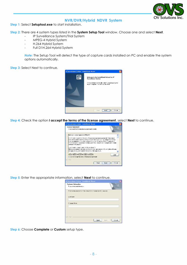
Step 1: Select Setuptool.exe to start installation.
Step 2: There are 4 system types listed in the System Setup Tool window. Choose one and select Next.
- IP Surveillance System/Trial System
- MPEG-4 Hybrid System
- H.264 Hybrid System
- Full D1H.264 Hybrid System
Note: The Setup Tool will detect the type of capture cards installed on PC and enable the system
options automatically.
Step 3: Select Next to continue.
Step 4: Check the option I accept the terms of the license agreement, select Next to continue.
Step 5: Enter the appropriate information, select Next to continue.
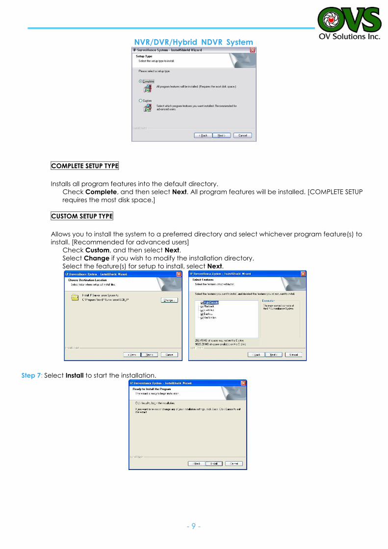
Step 6: Choose Complete or Custom setup type.
NVR/DVR/Hybrid NDVR System
- 9 -
COMPLETE SETUP TYPE
Installs all program features into the default directory.
Check Complete, and then select Next. All program features will be installed. [COMPLETE SETUP
requires the most disk space.]
CUSTOM SETUP TYPE
Allows you to install the system to a preferred directory and select whichever program feature(s) to
install. [Recommended for advanced users]
Check Custom, and then select Next.
Select Change if you wish to modify the installation directory.
Select the feature(s) for setup to install, select Next.
Step 7: Select Install to start the installation.

NVR/DVR/Hybrid NDVR System
- 10 -
Step 8: Select Finish, installation complete.
NVR/DVR/Hybrid NDVR System
- 11 -
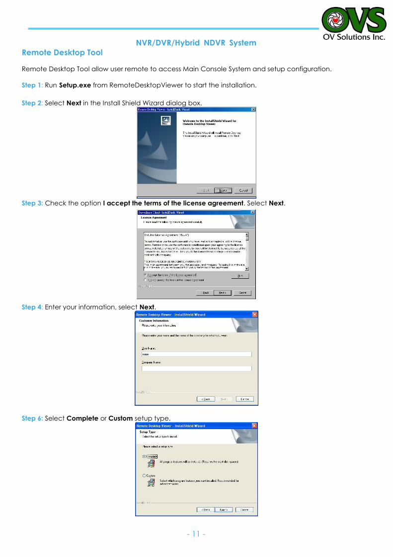
Remote Desktop Tool
Remote Desktop Tool allow user remote to access Main Console System and setup configuration.
Step 1: Run Setup.exe from RemoteDesktopViewer to start the installation.
Step 2: Select Next in the Install Shield Wizard dialog box.
Step 3: Check the option I accept the terms of the license agreement. Select Next.
Step 4: Enter your information, select Next.
Step 6: Select Complete or Custom setup type.
NVR/DVR/Hybrid NDVR System
- 12 -
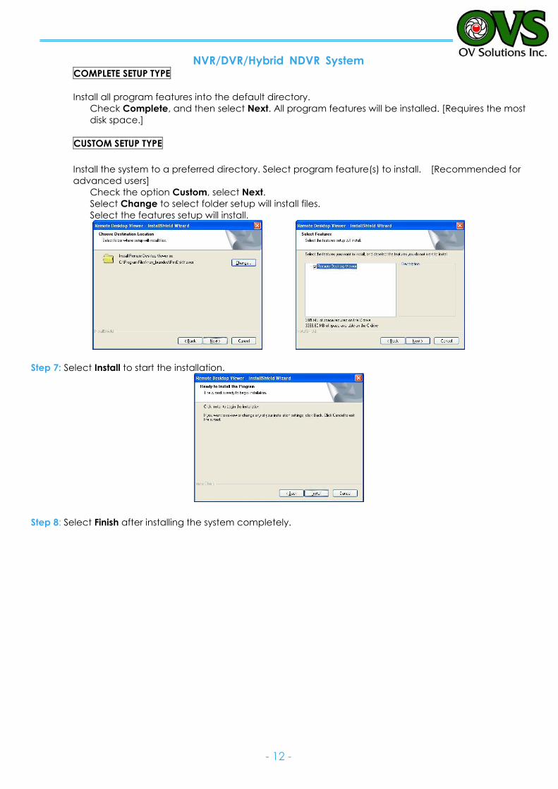
COMPLETE SETUP TYPE
Install all program features into the default directory.
Check Complete, and then select Next. All program features will be installed. [Requires the most
disk space.]
CUSTOM SETUP TYPE
Install the system to a preferred directory. Select program feature(s) to install. [Recommended for
advanced users]
Check the option Custom, select Next.
Select Change to select folder setup will install files.
Select the features setup will install.
Step 7: Select Install to start the installation.
Step 8: Select Finish after installing the system completely.
NVR/DVR/Hybrid NDVR System
- 13 -
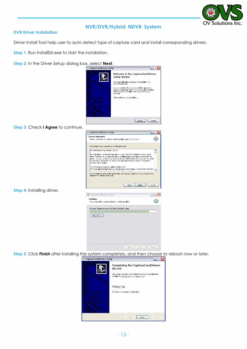
DVR Driver Installation
Driver Install Tool help user to auto detect type of capture card and install corresponding drivers.
Step 1: Run InstallDri.exe to start the installation.
Step 2: In the Driver Setup dialog box, select Next.
Step 3: Check I Agree to continue.
Step 4: Installing driver.
Step 5: Click Finish after installing the system completely, and then choose to reboot now or later.
NVR/DVR/Hybrid NDVR System
- 14 -
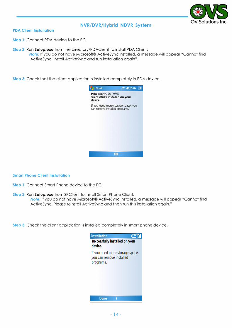
PDA Client Installation
Step 1: Connect PDA device to the PC.
Step 2: Run Setup.exe from the directory/PDAClient to install PDA Client.
Note: If you do not have Microsoft® ActiveSync installed, a message will appear “Cannot find
ActiveSync, install ActiveSync and run installation again”.
Step 3: Check that the client application is installed completely in PDA device.
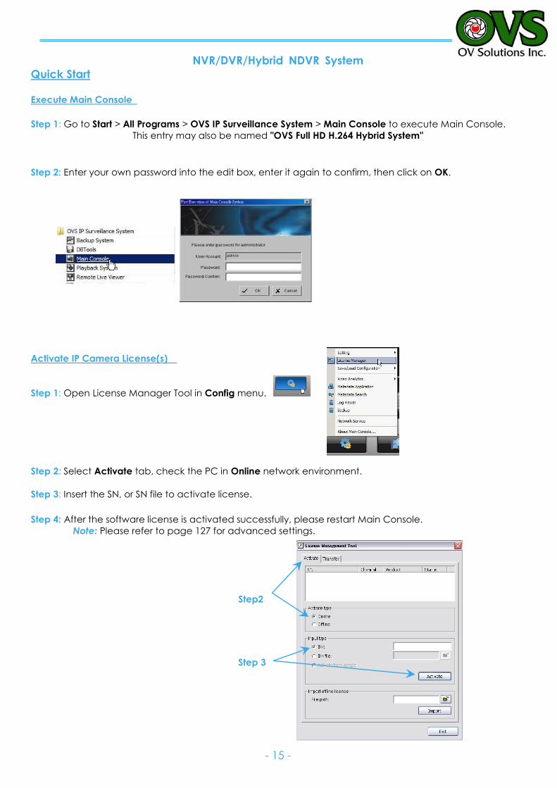
Smart Phone Client Installation
Step 1: Connect Smart Phone device to the PC.
Step 2: Run Setup.exe from SPClient to install Smart Phone Client.
Note: If you do not have Microsoft® ActiveSync installed, a message will appear “Cannot find
ActiveSync. Please reinstall ActiveSync and then run this installation again.”
Step 3: Check the client application is installed completely in smart phone device.
NVR/DVR/Hybrid NDVR System
- 15 -
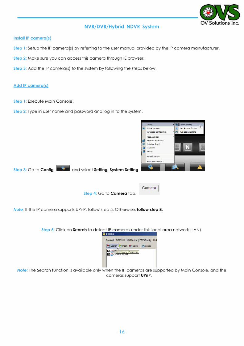
Quick Start Execute Main Console
Step 1: Go to Start > All Programs > OVS IP Surveillance System > Main Console to execute Main Console.
This entry may also be named "OVS Full HD H.264 Hybrid System"
Step 2: Enter your own password into the edit box, enter it again to confirm, then click on OK.
Activate IP Camera License(s)
Step 1: Open License Manager Tool in Config menu.
Step 2: Select Activate tab, check the PC in Online network environment.
Step 3: Insert the SN, or SN file to activate license.
Step 4: After the software license is activated successfully, please restart Main Console.
Note: Please refer to page 127 for advanced settings.
Step 3
Step2
NVR/DVR/Hybrid NDVR System
- 16 -
Install IP camera(s)
Step 1: Setup the IP camera(s) by referring to the user manual provided by the IP camera manufacturer.
Step 2: Make sure you can access this camera through IE browser.
Step 3: Add the IP camera(s) to the system by following the steps below.
Add IP camera(s)
Step 1: Execute Main Console.
Step 2: Type in user name and password and log in to the system.
Step 3: Go to Config and select Setting, System Setting
Step 4: Go to Camera tab.
Note: If the IP camera supports UPnP, follow step 5. Otherwise, follow step 8.
Step 5: Click on Search to detect IP cameras under this local area network (LAN).
Note: The Search function is available only when the IP cameras are supported by Main Console, and the
cameras support UPnP.
NVR/DVR/Hybrid NDVR System
- 17 -
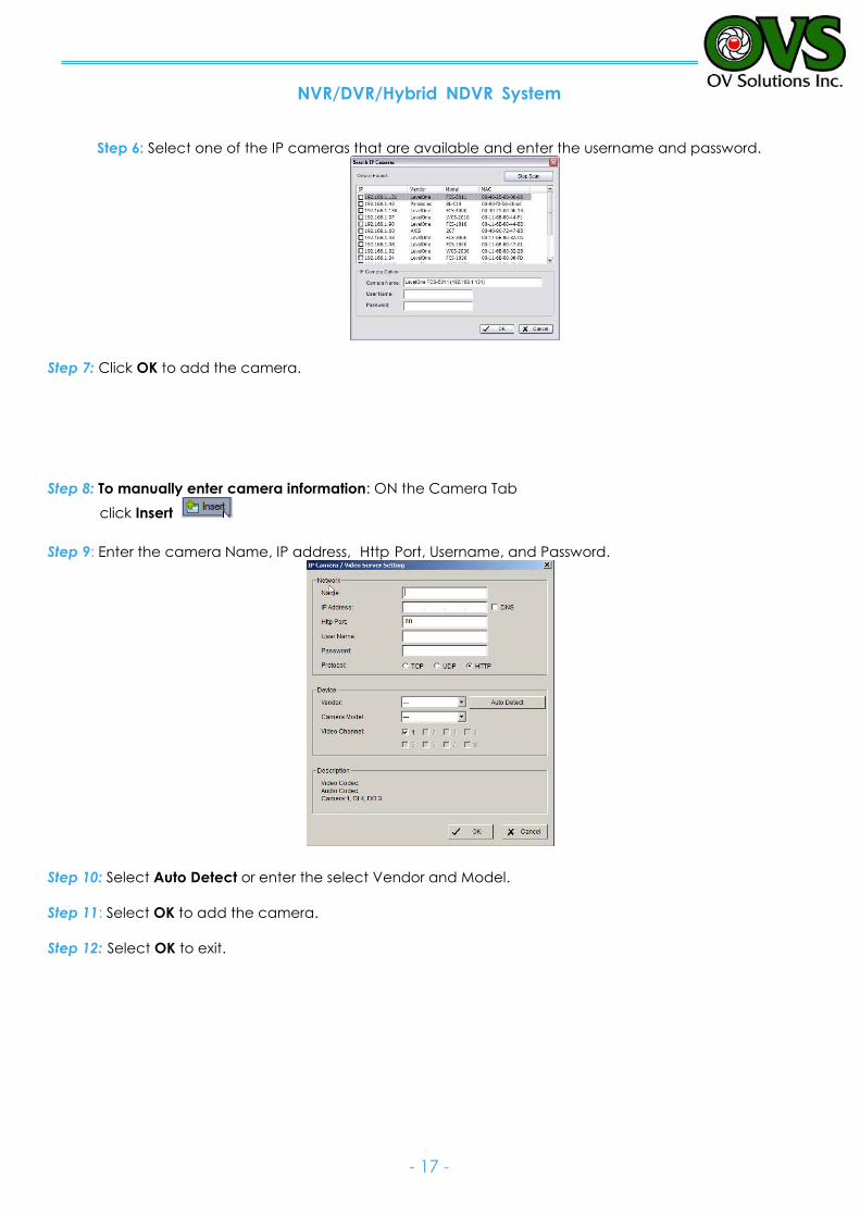
Step 6: Select one of the IP cameras that are available and enter the username and password.
Step 7: Click OK to add the camera.
Step 8: To manually enter camera information: ON the Camera Tab
click Insert
Step 9: Enter the camera Name, IP address, Http Port, Username, and Password.
Step 10: Select Auto Detect or enter the select Vendor and Model.
Step 11: Select OK to add the camera.
Step 12: Select OK to exit.
NVR/DVR/Hybrid NDVR System
- 18 -
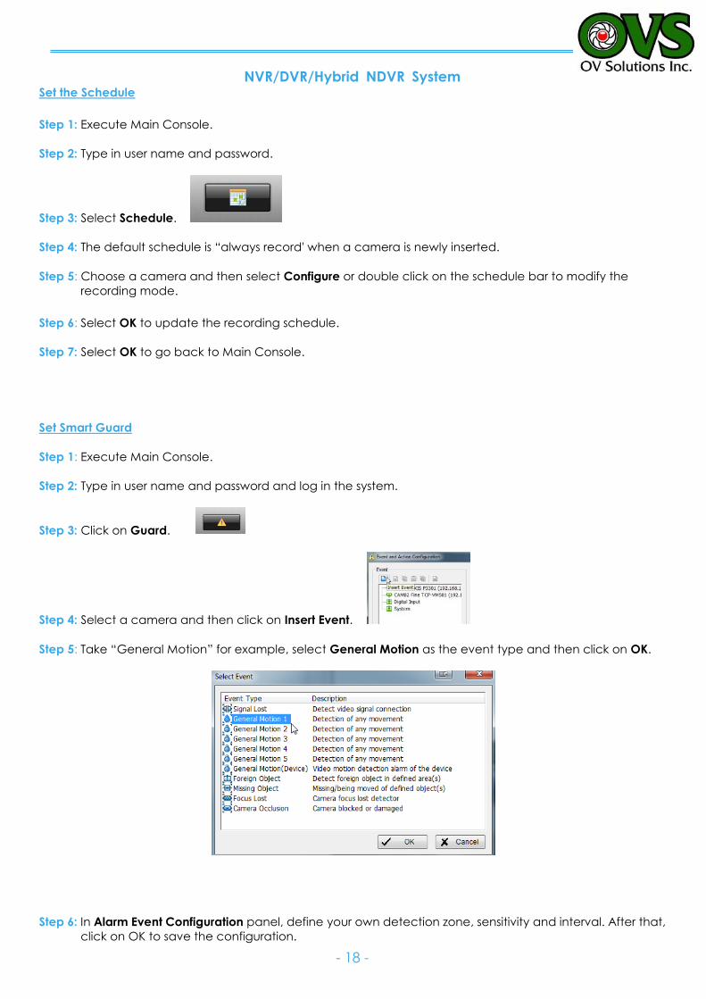
Set the Schedule
Step 1: Execute Main Console.
Step 2: Type in user name and password.
Step 3: Select Schedule.
Step 4: The default schedule is “always record' when a camera is newly inserted.
Step 5: Choose a camera and then select Configure or double click on the schedule bar to modify the
recording mode.
Step 6: Select OK to update the recording schedule.
Step 7: Select OK to go back to Main Console.
Set Smart Guard
Step 1: Execute Main Console.
Step 2: Type in user name and password and log in the system.
Step 3: Click on Guard.
Step 4: Select a camera and then click on Insert Event.
Step 5: Take “General Motion” for example, select General Motion as the event type and then click on OK.
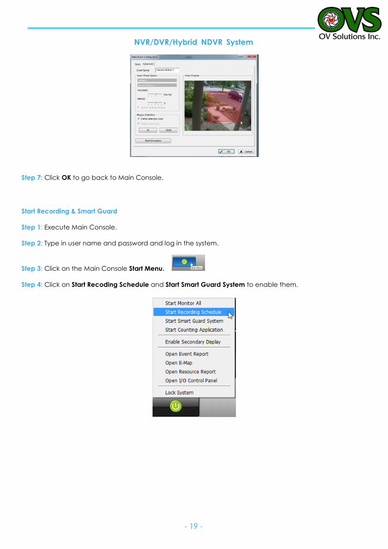
Step 6: In Alarm Event Configuration panel, define your own detection zone, sensitivity and interval. After that,
click on OK to save the configuration.
NVR/DVR/Hybrid NDVR System
- 19 -
Step 7: Click OK to go back to Main Console.
Start Recording & Smart Guard
Step 1: Execute Main Console.
Step 2: Type in user name and password and log in the system.
Step 3: Click on the Main Console Start Menu.
Step 4: Click on Start Recoding Schedule and Start Smart Guard System to enable them.
NVR/DVR/Hybrid NDVR System
- 20 -
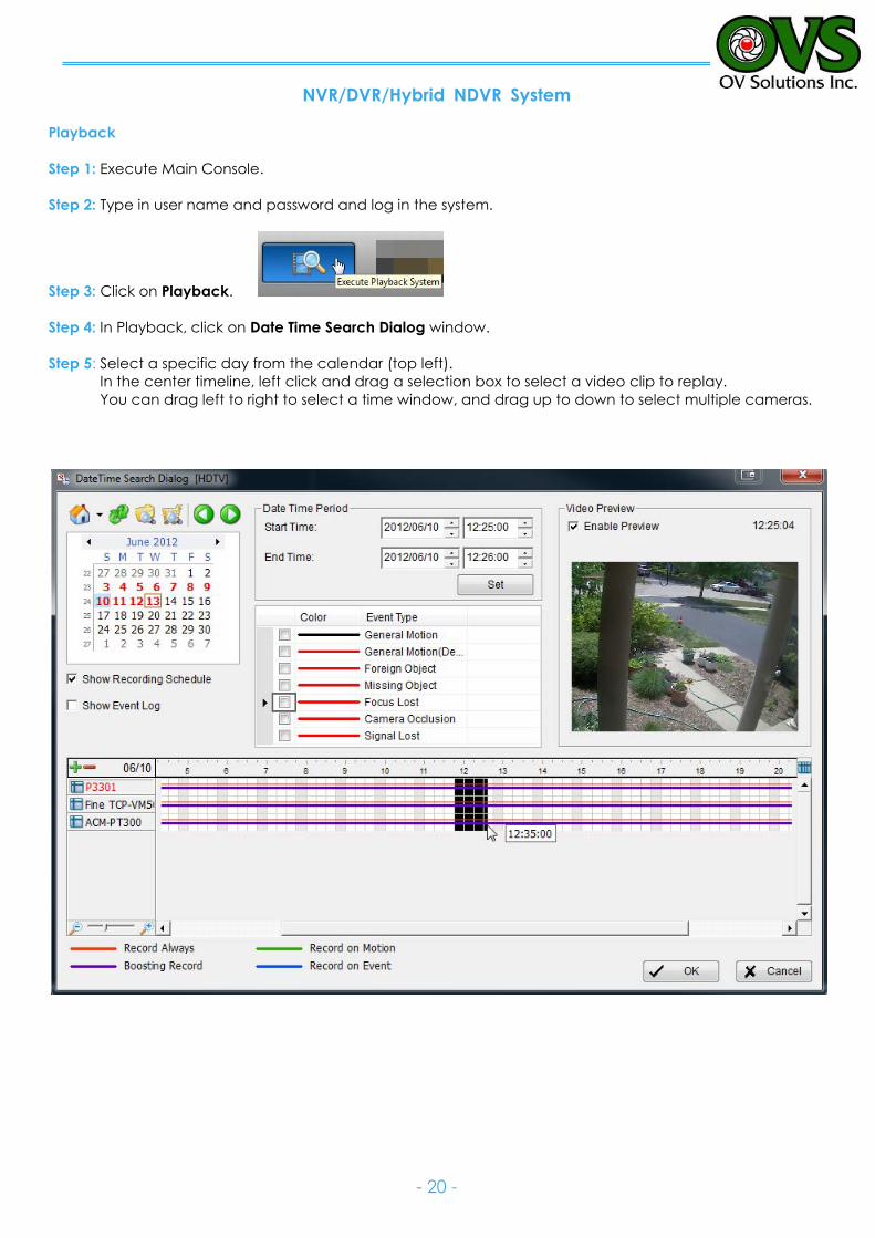
Playback
Step 1: Execute Main Console.
Step 2: Type in user name and password and log in the system.
Step 3: Click on Playback.
Step 4: In Playback, click on Date Time Search Dialog window.
Step 5: Select a specific day from the calendar (top left).
In the center timeline, left click and drag a selection box to select a video clip to replay.
You can drag left to right to select a time window, and drag up to down to select multiple cameras.
NVR/DVR/Hybrid NDVR System
- 21 -
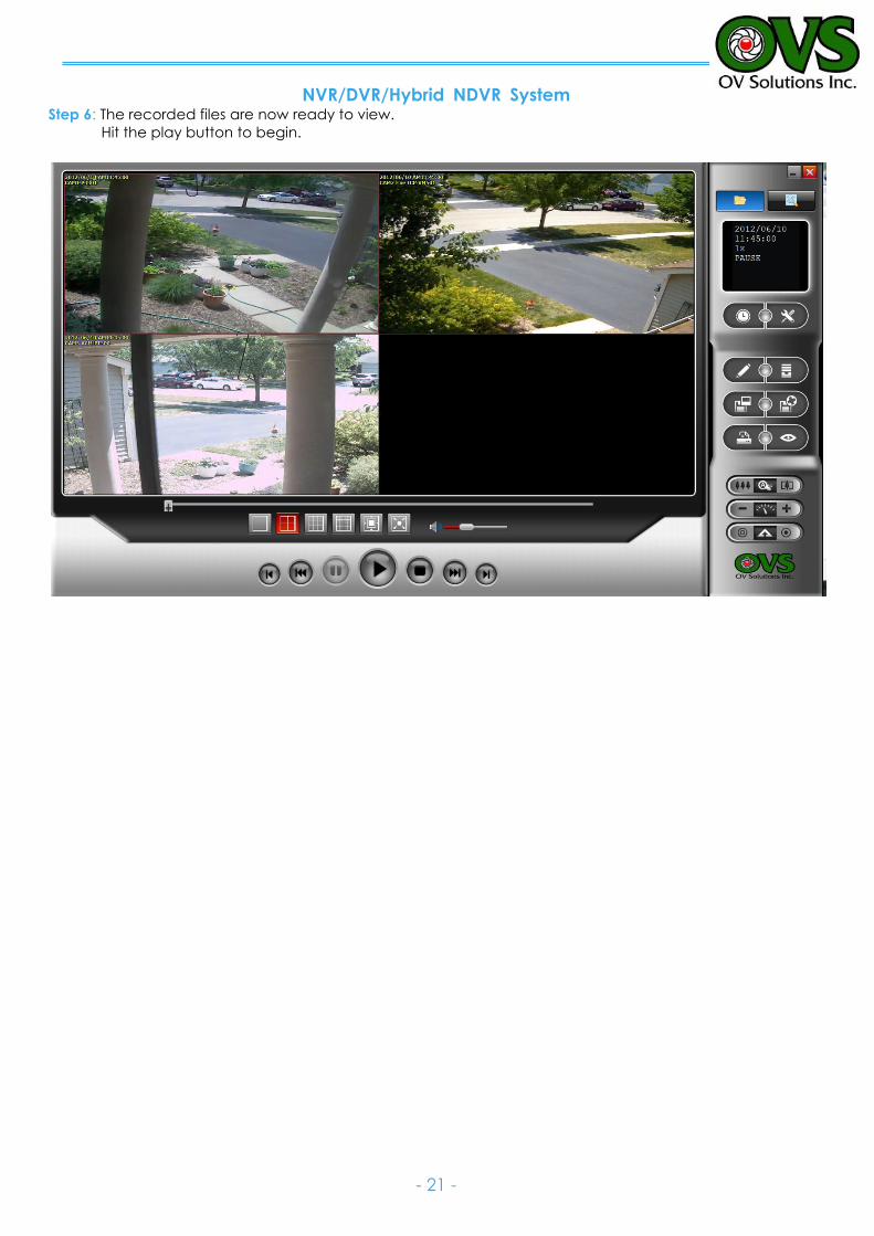
Step 6: The recorded files are now ready to view.
Hit the play button to begin.
NVR/DVR/Hybrid NDVR System
- 22 -
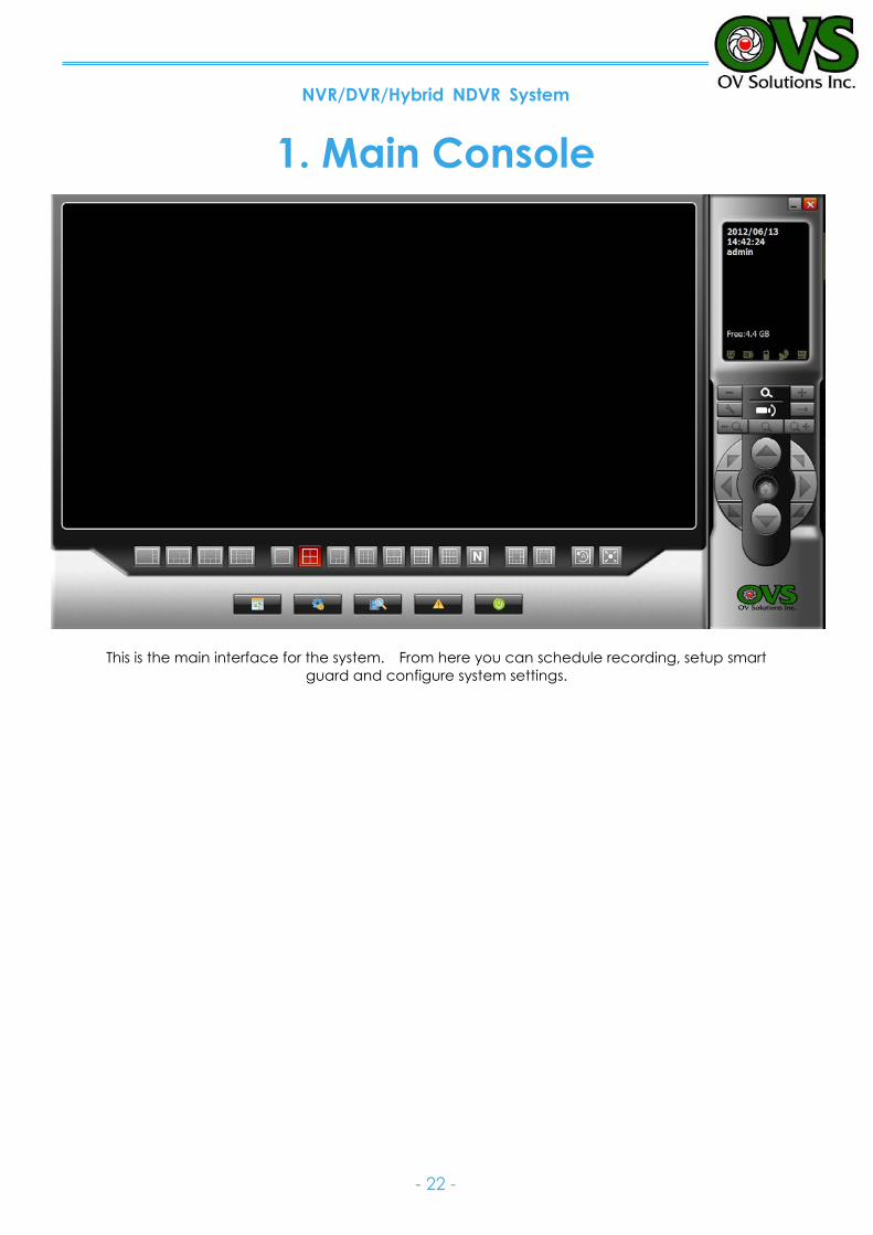
1. Main Console
This is the main interface for the system. From here you can schedule recording, setup smart
guard and configure system settings.
NVR/DVR/Hybrid NDVR System
- 23 -
Exit Minimize
Information Window
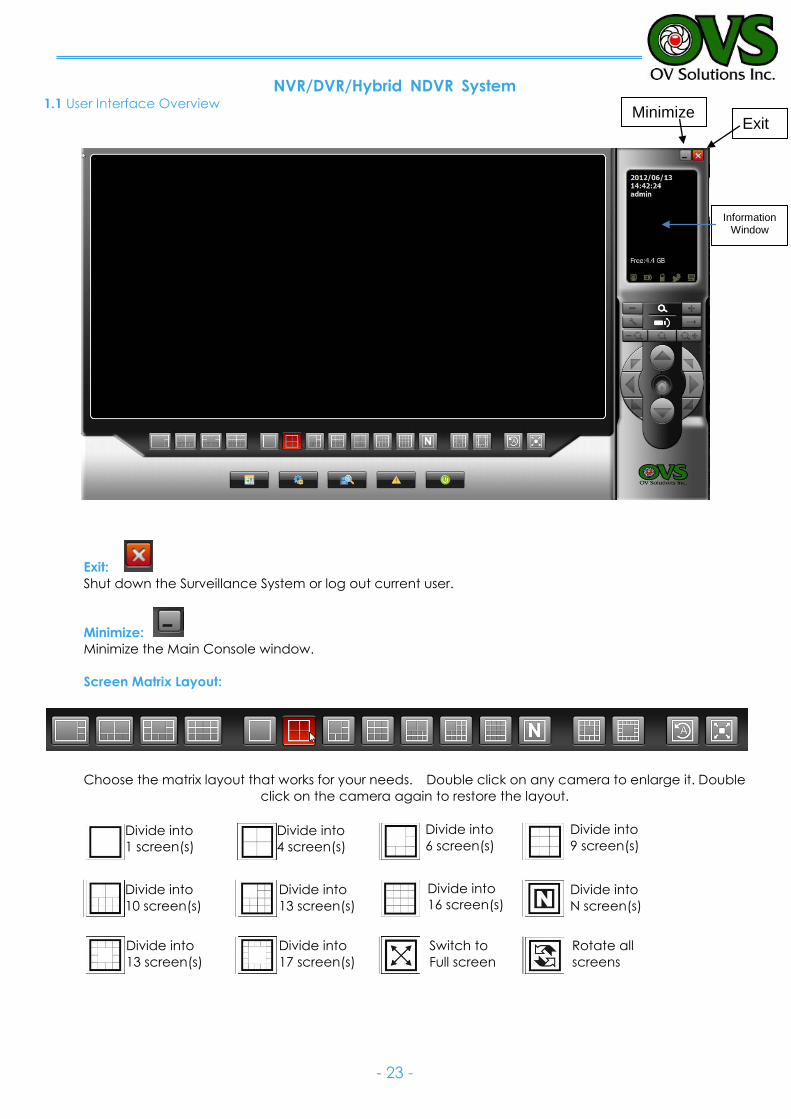
1.1 User Interface Overview
Exit:
Shut down the Surveillance System or log out current user.
Minimize:
Minimize the Main Console window.
Screen Matrix Layout:
Choose the matrix layout that works for your needs. Double click on any camera to enlarge it. Double
click on the camera again to restore the layout.
Divide into
1 screen(s)
Divide into
4 screen(s)
Divide into
6 screen(s)
Divide into
9 screen(s)
Divide into
10 screen(s)
)
Divide into
13 screen(s)
3 screen(s)
Divide into
16 screen(s) Divide into
N screen(s)
Divide into
13 screen(s)
Divide into
17 screen(s)
Switch to
Full screen
Rotate all
screens
NVR/DVR/Hybrid NDVR System
- 24 -
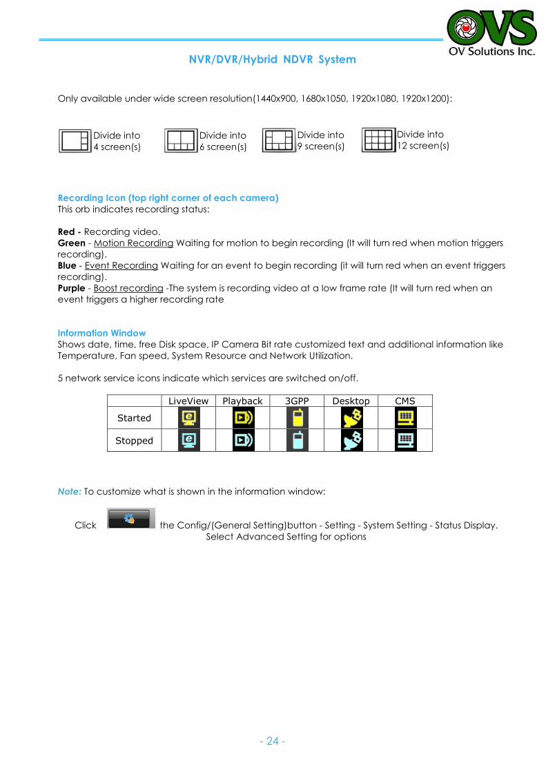
Only available under wide screen resolution(1440x900, 1680x1050, 1920x1080, 1920x1200):
Recording Icon (top right corner of each camera)
This orb indicates recording status:
Red - Recording video.
Green - Motion Recording Waiting for motion to begin recording (It will turn red when motion triggers
recording).
Blue - Event Recording Waiting for an event to begin recording (it will turn red when an event triggers
recording).
Purple - Boost recording -The system is recording video at a low frame rate (It will turn red when an
event triggers a higher recording rate
Information Window Shows date, time, free Disk space, IP Camera Bit rate customized text and additional information like
Temperature, Fan speed, System Resource and Network Utilization.
5 network service icons indicate which services are switched on/off.
LiveView Playback 3GPP Desktop CMS
Started
Stopped
Note: To customize what is shown in the information window:
Click the Config/(General Setting)button - Setting - System Setting - Status Display.
Select Advanced Setting for options
Divide into
12 screen(s) Divide into
9 screen(s) Divide into
6 screen(s)
Divide into
4 screen(s)
NVR/DVR/Hybrid NDVR System
- 25 -
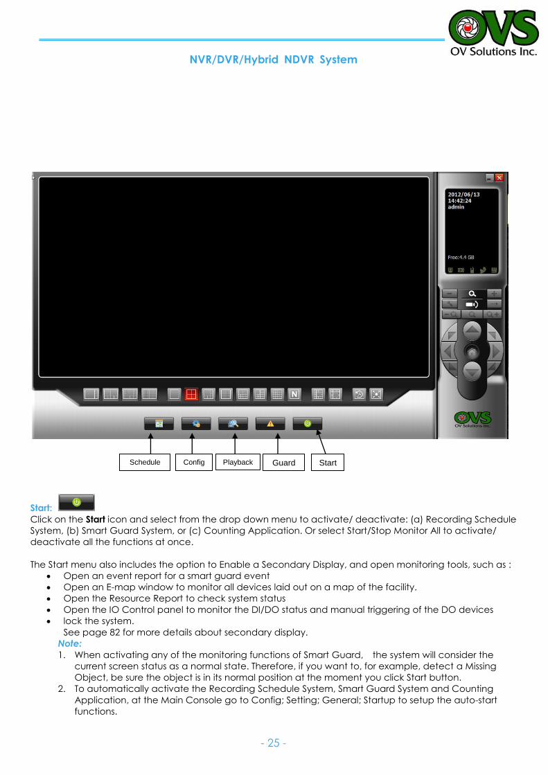
Start:
Click on the Start icon and select from the drop down menu to activate/ deactivate: (a) Recording Schedule
System, (b) Smart Guard System, or (c) Counting Application. Or select Start/Stop Monitor All to activate/
deactivate all the functions at once.
The Start menu also includes the option to Enable a Secondary Display, and open monitoring tools, such as :
Open an event report for a smart guard event
Open an E-map window to monitor all devices laid out on a map of the facility.
Open the Resource Report to check system status
Open the IO Control panel to monitor the DI/DO status and manual triggering of the DO devices
lock the system.
See page 82 for more details about secondary display.
Note:
1. When activating any of the monitoring functions of Smart Guard, the system will consider the
current screen status as a normal state. Therefore, if you want to, for example, detect a Missing
Object, be sure the object is in its normal position at the moment you click Start button.
2. To automatically activate the Recording Schedule System, Smart Guard System and Counting
Application, at the Main Console go to Config; Setting; General; Startup to setup the auto-start
functions.
Start Guard Playback Config Schedule
NVR/DVR/Hybrid NDVR System
- 26 -
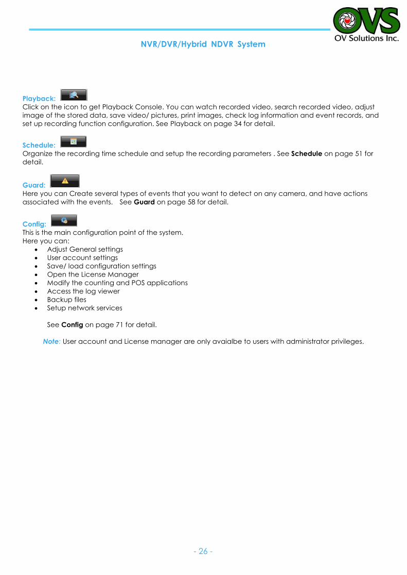
Playback:
Click on the icon to get Playback Console. You can watch recorded video, search recorded video, adjust
image of the stored data, save video/ pictures, print images, check log information and event records, and
set up recording function configuration. See Playback on page 34 for detail.
Schedule:
Organize the recording time schedule and setup the recording parameters . See Schedule on page 51 for
detail.
Guard:
Here you can Create several types of events that you want to detect on any camera, and have actions
associated with the events. See Guard on page 58 for detail.
Config:
This is the main configuration point of the system.
Here you can:
Adjust General settings
User account settings
Save/ load configuration settings
Open the License Manager
Modify the counting and POS applications
Access the log viewer
Backup files
Setup network services
See Config on page 71 for detail.
Note: User account and License manager are only avaialbe to users with administrator privileges.
NVR/DVR/Hybrid NDVR System
- 27 -
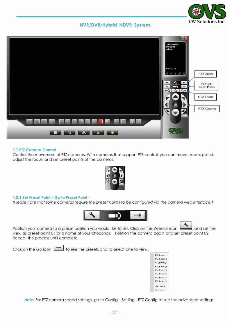
1.2 PTZ Camera Control
Control the movement of PTZ cameras. With cameras that support PTZ control, you can move, zoom, patrol,
adjust the focus, and set preset points of the cameras.
1.2.1 Set Preset Point / Go to Preset Point -
(Please note that some cameras require the preset points to be configured via the camera web interface.)
Position your camera to a preset position you would like to set. Click on the Wrench icon and set the
view as preset point 01(or a name of your choosing). Position the camera again and set preset point 02.
Repeat the process until complete.
Click on the Go icon to see the presets and to select one to view.
Note: For PTZ camera speed settings, go to Config – Setting - PTZ Config to see the advanced settings.
PTZ Control
PTZ Set / Preset Points
PTZ Zoom
PTZ Focus
NVR/DVR/Hybrid NDVR System
- 28 -
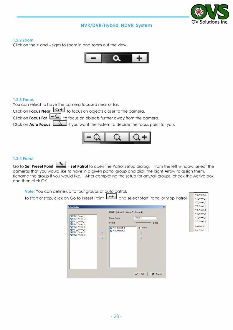
1.2.2 Zoom
Click on the + and – signs to zoom in and zoom out the view.
1.2.3 Focus
You can select to have the camera focused near or far.
Click on Focus Near to focus on objects closer to the camera.
Click on Focus Far to focus on objects further away from the camera.
Click on Auto Focus if you want the system to decide the focus point for you.
1.2.4 Patrol
Go to Set Preset Point - Set Patrol to open the Patrol Setup dialog. From the left window, select the
cameras that you would like to have in a given patrol group and click the Right Arrow to assign them.
Rename the group if you would like. After completing the setup for any/all groups, check the Active box,
and then click OK.
Note: You can define up to four groups of auto patrol.
To start or stop, click on Go to Preset Point , and select Start Patrol or Stop Patrol.
NVR/DVR/Hybrid NDVR System
- 29 -
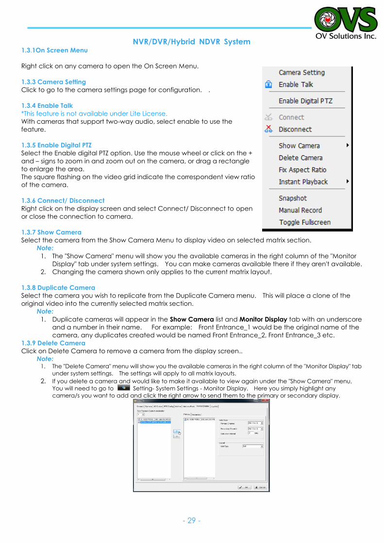
1.3.1On Screen Menu
Right click on any camera to open the On Screen Menu.
1.3.3 Camera Setting
Click to go to the camera settings page for configuration. .
1.3.4 Enable Talk
*This feature is not available under Lite License.
With cameras that support two-way audio, select enable to use the
feature.
1.3.5 Enable Digital PTZ
Select the Enable digital PTZ option. Use the mouse wheel or click on the +
and – signs to zoom in and zoom out on the camera, or drag a rectangle
to enlarge the area.
The square flashing on the video grid indicate the correspondent view ratio
of the camera.
1.3.6 Connect/ Disconnect
Right click on the display screen and select Connect/ Disconnect to open
or close the connection to camera.
1.3.7 Show Camera
Select the camera from the Show Camera Menu to display video on selected matrix section.
Note:
1. The "Show Camera" menu will show you the available cameras in the right column of the "Monitor
Display" tab under system settings. You can make cameras available there if they aren't available.
2. Changing the camera shown only applies to the current matrix layout.
1.3.8 Duplicate Camera
Select the camera you wish to replicate from the Duplicate Camera menu. This will place a clone of the
original video into the currently selected matrix section.
Note:
1. Duplicate cameras will appear in the Show Camera list and Monitor Display tab with an underscore
and a number in their name. For example: Front Entrance_1 would be the original name of the
camera, any duplicates created would be named Front Entrance_2, Front Entrance_3 etc.
1.3.9 Delete Camera
Click on Delete Camera to remove a camera from the display screen..
Note: 1. The "Delete Camera" menu will show you the available cameras in the right column of the "Monitor Display" tab
under system settings. The settings will apply to all matrix layouts.
2. If you delete a camera and would like to make it available to view again under the "Show Camera" menu,
You will need to go to Setting- System Settings - Monitor Display. Here you simply highlight any
camera/s you want to add and click the right arrow to send them to the primary or secondary display.
NVR/DVR/Hybrid NDVR System
- 30 -
1.3.10 Enable Digital PTZ
To enable the PTZ functions of the camera, select the Enable digital PTZ option. Use mouse wheel or click on
the + and – signs to zoom in and zoom out on the camera, or drag a rectangle to enlarge the area.
The square flashing on the video grid indicate the correspondent view ratio of the camera.
1.3.11 Fix Aspect Ratio
For some special camera resolutions, you cam enable Fix Aspect Ratio to view the original ratio video, or
disable this option to stretch 3:4 to fit the window.
1.3.12 Instant Playback
*This feature is not available under Lite License.
Select Instant Playback and choose a time window of 1, 3 , or 5 minutes.
Refer to 1.5 Instant Playback section for details.
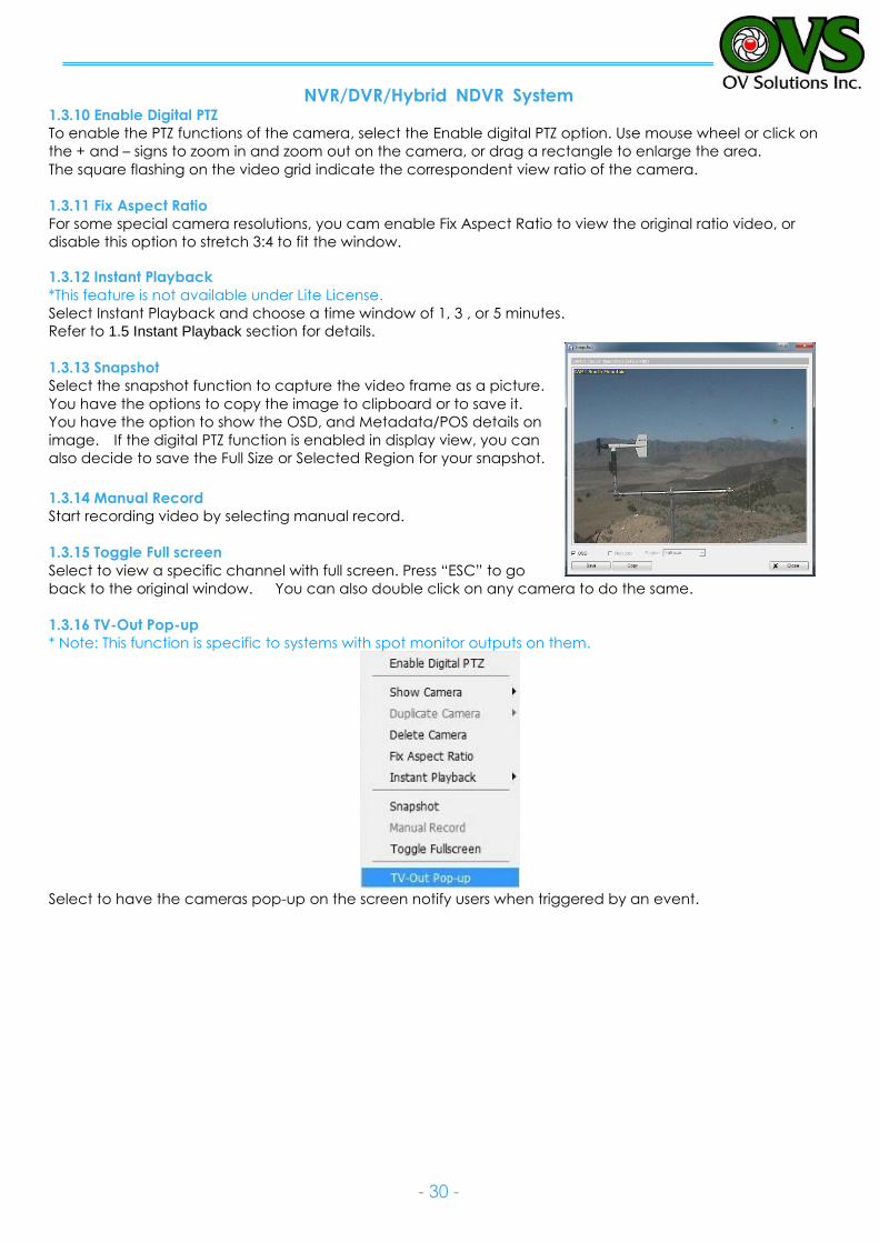
1.3.13 Snapshot
Select the snapshot function to capture the video frame as a picture.
You have the options to copy the image to clipboard or to save it.
You have the option to show the OSD, and Metadata/POS details on
image. If the digital PTZ function is enabled in display view, you can
also decide to save the Full Size or Selected Region for your snapshot.
1.3.14 Manual Record
Start recording video by selecting manual record.
1.3.15 Toggle Full screen
Select to view a specific channel with full screen. Press “ESC” to go
back to the original window. You can also double click on any camera to do the same.
1.3.16 TV-Out Pop-up
* Note: This function is specific to systems with spot monitor outputs on them.
Select to have the cameras pop-up on the screen notify users when triggered by an event.
NVR/DVR/Hybrid NDVR System
- 31 -
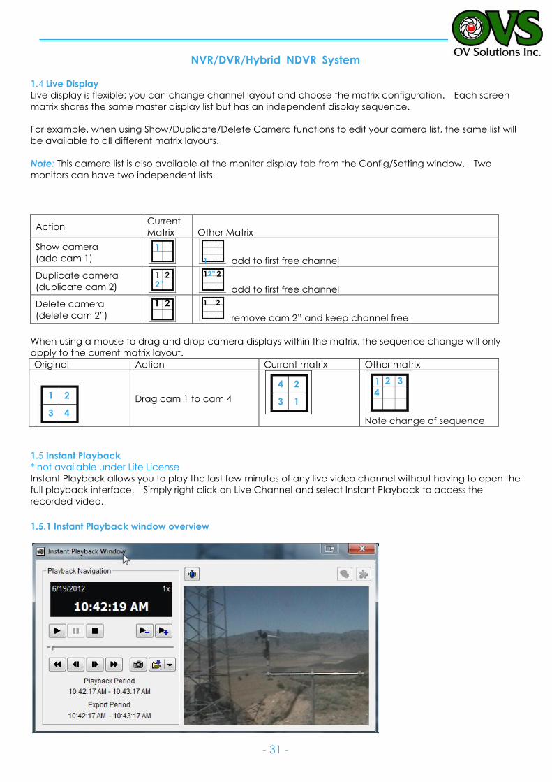
1.4 Live Display
Live display is flexible; you can change channel layout and choose the matrix configuration. Each screen
matrix shares the same master display list but has an independent display sequence.
For example, when using Show/Duplicate/Delete Camera functions to edit your camera list, the same list will
be available to all different matrix layouts.
Note: This camera list is also available at the monitor display tab from the Config/Setting window. Two
monitors can have two independent lists.
Action Current
Matrix Other Matrix
Show camera
(add cam 1) add to first free channel
Duplicate camera
(duplicate cam 2) add to first free channel
Delete camera
(delete cam 2”) remove cam 2” and keep channel free
When using a mouse to drag and drop camera displays within the matrix, the sequence change will only
apply to the current matrix layout.
Original Action Current matrix Other matrix
Drag cam 1 to cam 4
Note change of sequence
1.5 Instant Playback
* not available under Lite License
Instant Playback allows you to play the last few minutes of any live video channel without having to open the
full playback interface. Simply right click on Live Channel and select Instant Playback to access the
recorded video.
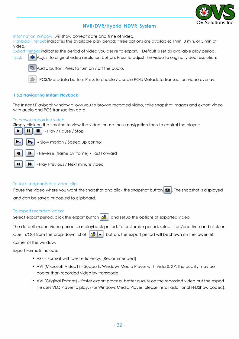
1.5.1 Instant Playback window overview
1
1 2 2”
1
1 2 2”
1 2 1 2
1 2
3 4
4 2
3 1
1 2 3
4
NVR/DVR/Hybrid NDVR System
- 32 -
Information Window: will show correct date and time of video.
Playback Period: indicates the available play period; three options are available: 1min, 3 min, or 5 min of
video.
Export Period: indicates the period of video you desire to export. Default is set as available play period.
Tool: Adjust to original video resolution button: Press to adjust the video to original video resolution.
Audio button: Press to turn on / off the audio.
POS/Metadata button: Press to enable / disable POS/Metadata transaction video overlay.
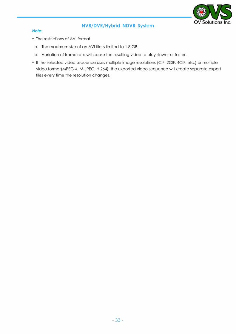
1.5.2 Navigating Instant Playback
The Instant Playback window allows you to browse recorded video, take snapshot images and export video
with audio and POS transaction data.
To browse recorded video:
Simply click on the timeline to view the video, or use these navigation tools to control the player:
- Play / Pause / Stop
- Slow motion / Speed up control
- Reverse [frame by frame] / Fast Forward
- Play Previous / Next minute video
To take snapshots of a video clip:
Pause the video where you want the snapshot and click the snapshot button . The snapshot is displayed
and can be saved or copied to clipboard.
To export recorded video:
Select export period, click the export button , and setup the options of exported video.
The default export video period is as playback period. To customize period, select start/end time and click on
Cue In/Out from the drop-down list of button, the export period will be shown on the lower-left
corner of the window.
Export Formats include:
ASF – Format with best efficiency. [Recommended]
AVI (Microsoft Video1) – Supports Windows Media Player with Vista & XP, the quality may be
poorer than recorded video by transcode.
AVI (Original Format) – faster export process, better quality on the recorded video but the export
file uses VLC Player to play. (For Windows Media Player, please install additional FFDShow codec).
NVR/DVR/Hybrid NDVR System
- 33 -
Note:
The restrictions of AVI format.
a. The maximum size of an AVI file is limited to 1.8 GB.
b. Variation of frame rate will cause the resulting video to play slower or faster.
If the selected video sequence uses multiple image resolutions (CIF, 2CIF, 4CIF, etc.) or multiple
video format(MPEG-4, M-JPEG, H.264), the exported video sequence will create separate export
files every time the resolution changes.
NVR/DVR/Hybrid NDVR System
- 34 -
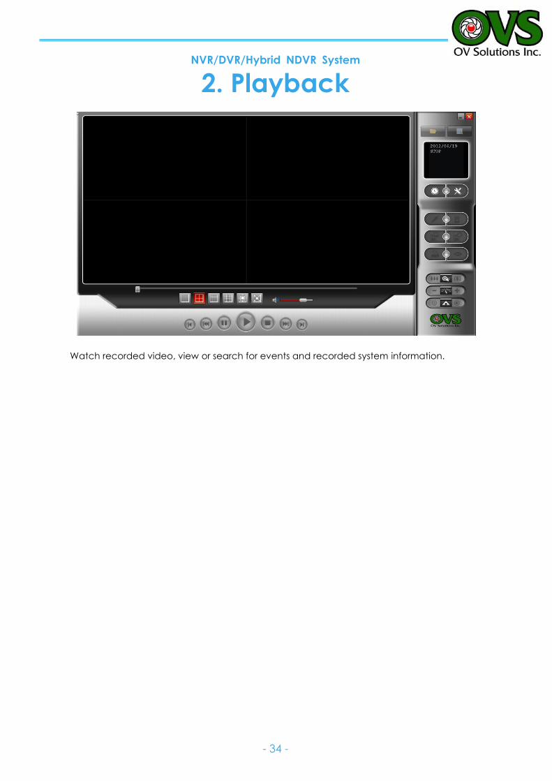
2. Playback
Watch recorded video, view or search for events and recorded system information.
NVR/DVR/Hybrid NDVR System
- 35 -
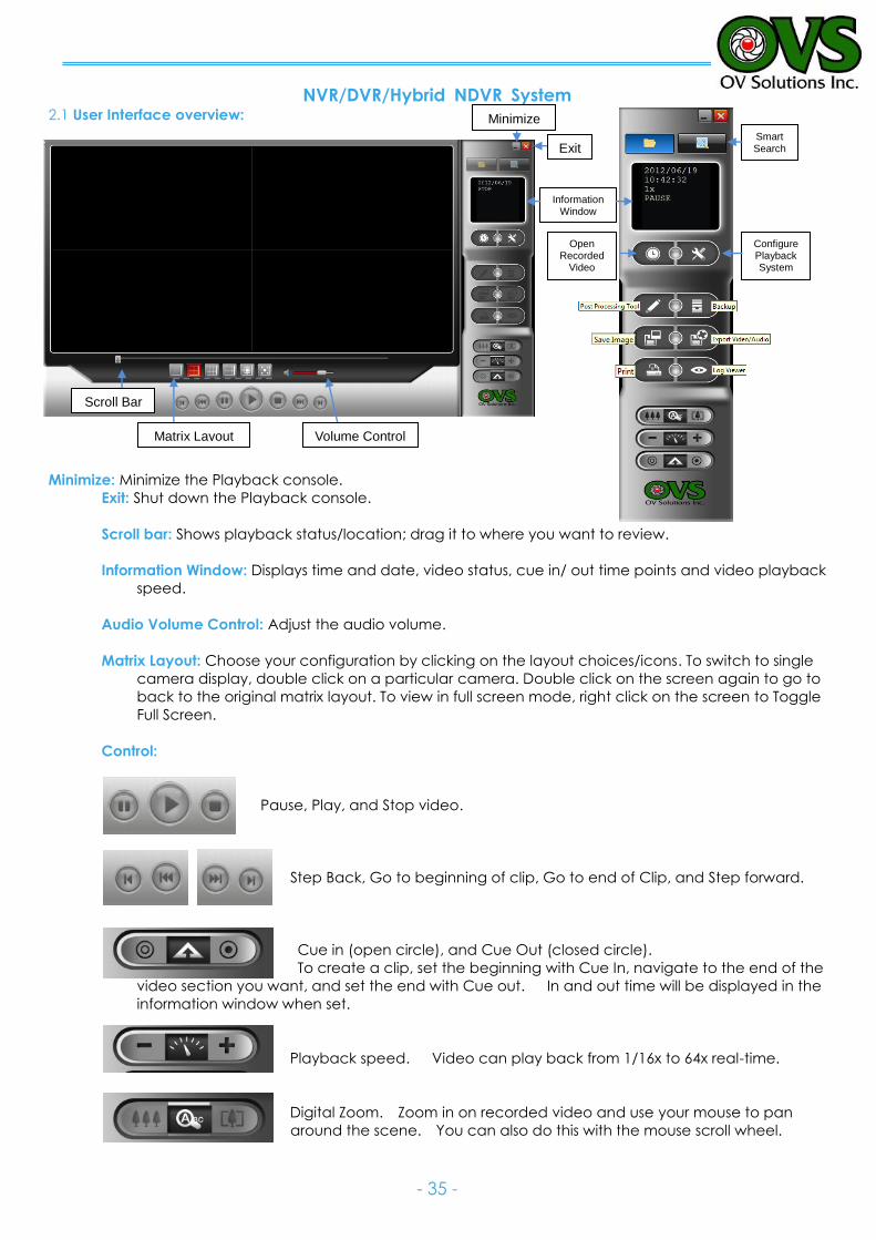
2.1 User Interface overview:
Minimize: Minimize the Playback console.
Exit: Shut down the Playback console.
Scroll bar: Shows playback status/location; drag it to where you want to review.
Information Window: Displays time and date, video status, cue in/ out time points and video playback
speed.
Audio Volume Control: Adjust the audio volume.
Matrix Layout: Choose your configuration by clicking on the layout choices/icons. To switch to single
camera display, double click on a particular camera. Double click on the screen again to go to
back to the original matrix layout. To view in full screen mode, right click on the screen to Toggle
Full Screen.
Control:
Pause, Play, and Stop video.
Step Back, Go to beginning of clip, Go to end of Clip, and Step forward.
Cue in (open circle), and Cue Out (closed circle).
To create a clip, set the beginning with Cue In, navigate to the end of the
video section you want, and set the end with Cue out. In and out time will be displayed in the
information window when set.
Playback speed. Video can play back from 1/16x to 64x real-time.
Digital Zoom. Zoom in on recorded video and use your mouse to pan
around the scene. You can also do this with the mouse scroll wheel.
Scroll Bar
Matrix Layout Volume Control
Minimize
Exit
Information Window
SmartSearch
Open Recorded
Video
Configure Playback System
NVR/DVR/Hybrid NDVR System
- 36 -
2.2 Open Recorded Video / Date Time Search Dialog
Click on the Open Recorded Video / Date Time Search Dialog button to access the Date-Time Panel.
This interface also open by default when you launch the playback window. See Below.
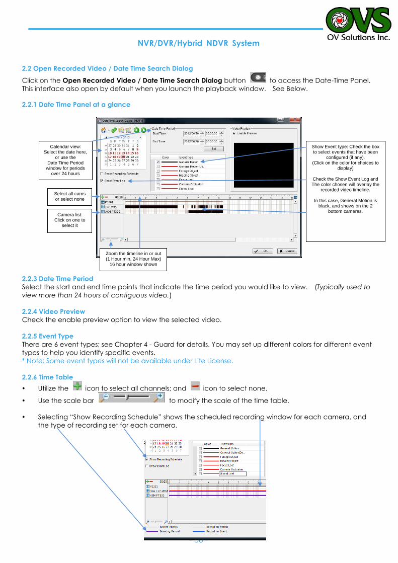
2.2.1 Date Time Panel at a glance
2.2.3 Date Time Period
Select the start and end time points that indicate the time period you would like to view. (Typically used to
view more than 24 hours of contiguous video.)
2.2.4 Video Preview
Check the enable preview option to view the selected video.
2.2.5 Event Type
There are 6 event types; see Chapter 4 - Guard for details. You may set up different colors for different event
types to help you identify specific events.
* Note: Some event types will not be available under Lite License.
2.2.6 Time Table
Utilize the icon to select all channels; and icon to select none.
Use the scale bar to modify the scale of the time table.
Selecting “Show Recording Schedule” shows the scheduled recording window for each camera, and
the type of recording set for each camera.
Select all cams or select none
Zoom the timeline in or out (1 Hour min, 24 Hour Max)
16 hour window shown
Camera list: Click on one to
select it
Calendar view: Select the date here,
or use the Date Time Period
window for periods over 24 hours
Show Event type: Check the box to select events that have been
configured (if any). (Click on the color for choices to
display)
Check the Show Event Log and The color chosen will overlay the
recorded video timeline.
In this case, General Motion is black, and shows on the 2
bottom cameras.
NVR/DVR/Hybrid NDVR System
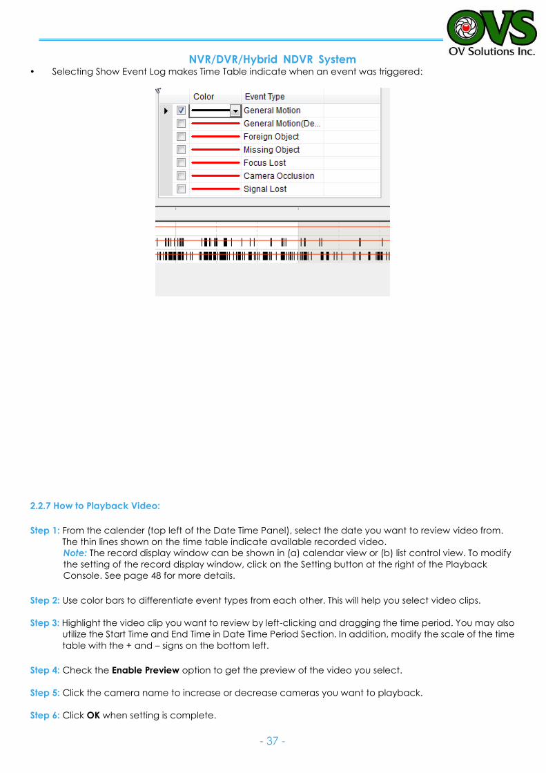
- 37 -
Selecting Show Event Log makes Time Table indicate when an event was triggered:
2.2.7 How to Playback Video:
Step 1: From the calender (top left of the Date Time Panel), select the date you want to review video from.
The thin lines shown on the time table indicate available recorded video.
Note: The record display window can be shown in (a) calendar view or (b) list control view. To modify
the setting of the record display window, click on the Setting button at the right of the Playback
Console. See page 48 for more details.
Step 2: Use color bars to differentiate event types from each other. This will help you select video clips.
Step 3: Highlight the video clip you want to review by left-clicking and dragging the time period. You may also
utilize the Start Time and End Time in Date Time Period Section. In addition, modify the scale of the time
table with the + and – signs on the bottom left.
Step 4: Check the Enable Preview option to get the preview of the video you select.
Step 5: Click the camera name to increase or decrease cameras you want to playback.
Step 6: Click OK when setting is complete.
NVR/DVR/Hybrid NDVR System
- 38 -
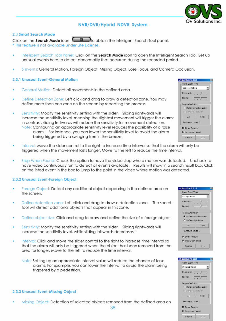
2.3 Smart Search Mode
Click on the Search Mode icon to obtain the Intelligent Search Tool panel.
* This feature is not available under Lite License.
Intelligent Search Tool Panel: Click on the Search Mode icon to open the Intelligent Search Tool. Set up
unusual events here to detect abnormality that occurred during the recorded period.
5 events: General Motion, Foreign Object, Missing Object, Lose Focus, and Camera Occlusion.
2.3.1 Unusual Event-General Motion
General Motion: Detect all movements in the defined area.
Define Detection Zone: Left click and drag to draw a detection zone. You may
define more than one zone on the screen by repeating the process.
Sensitivity: Modify the sensitivity setting with the slider. Sliding rightwards will
increase the sensitivity level, meaning the slightest movement will trigger the alarm;
in contrast, sliding leftwards will reduce the sensitivity for movement detection.
Note: Configuring an appropriate sensitivity level reduces the possibility of a false
alarm. For instance, you can lower the sensitivity level to avoid the alarm
being triggered by a swinging tree in the breeze.
Interval: Move the slider control to the right to increase time interval so that the alarm will only be
triggered when the movement lasts longer. Move to the left to reduce the time interval.
Stop When Found: Check the option to have the video stop where motion was detected. Uncheck to
have video continuously run to detect all events available. Results will show in a search result box. Click
on the listed event in the box to jump to the point in the video where motion was detected.
2.3.2 Unusual Event-Foreign Object
Foreign Object: Detect any additional object appearing in the defined area on
the screen.
Define detection zone: Left click and drag to draw a detection zone. The search
tool will detect additional objects that appear in this zone.
Define object size: Click and drag to draw and define the size of a foreign object.
Sensitivity: Modify the sensitivity setting with the slider. Sliding rightwards will
increase the sensitivity level, while sliding leftwards decreases it.
Interval: Click and move the slider control to the right to increase time interval so
that the alarm will only be triggered when the object has been removed from the
area for longer. Move to the left to reduce the time interval.
Note: Setting up an appropriate Interval value will reduce the chance of false
alarms. For example, you can lower the Interval to avoid the alarm being
triggered by a pedestrian.
2.3.3 Unusual Event-Missing Object
Missing Object: Detection of selected objects removed from the defined area on
NVR/DVR/Hybrid NDVR System
- 39 -
the screen.
Define detection zone: Left click and drag to draw a detection zone. The search tool will detect
selected objects removed in this zone.
Sensitivity: Modify the sensitivity setting with the slider. Sliding rightwards will increase the sensitivity level,
while sliding leftwards decreases it.
Interval: Click and move the slider control to the right to increase time interval so that the alarm will only
be triggered when the movement lasts longer. Move to the left to reduce the time interval.
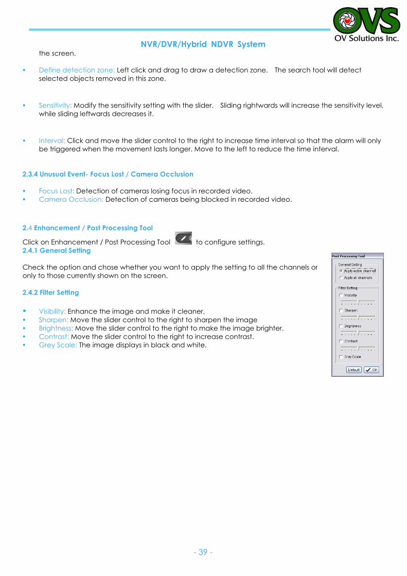
2.3.4 Unusual Event- Focus Lost / Camera Occlusion
Focus Lost: Detection of cameras losing focus in recorded video.
Camera Occlusion: Detection of cameras being blocked in recorded video.
2.4 Enhancement / Post Processing Tool
Click on Enhancement / Post Processing Tool to configure settings.
2.4.1 General Setting
Check the option and chose whether you want to apply the setting to all the channels or
only to those currently shown on the screen.
2.4.2 Filter Setting
Visibility: Enhance the image and make it cleaner. Sharpen: Move the slider control to the right to sharpen the image
Brightness: Move the slider control to the right to make the image brighter.
Contrast: Move the slider control to the right to increase contrast.
Grey Scale: The image displays in black and white.
NVR/DVR/Hybrid NDVR System
- 40 -
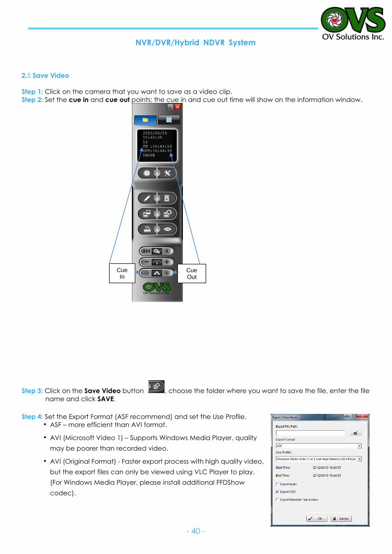
2.5 Save Video
Step 1: Click on the camera that you want to save as a video clip.
Step 2: Set the cue in and cue out points; the cue in and cue out time will show on the information window.
Step 3: Click on the Save Video button , choose the folder where you want to save the file, enter the file
name and click SAVE.
Step 4: Set the Export Format (ASF recommend) and set the Use Profile.
ASF – more efficient than AVI format.
AVI (Microsoft Video 1) – Supports Windows Media Player, quality
may be poorer than recorded video.
AVI (Original Format) - Faster export process with high quality video,
but the export files can only be viewed using VLC Player to play.
(For Windows Media Player, please install additional FFDShow
codec).
Cue Out
Cue In
NVR/DVR/Hybrid NDVR System
- 41 -
Note:
Restrictions of AVI format:
a. The maximum size of an AVI file is limited to 4 GB.
b. Variation of frame rate will cause the resulting video to play slower or faster.
If the selected video sequence uses multiple image resolutions (CIF, 2CIF, 4CIF, etc.) or multiple video
format (MPEG-4, M-JPEG, H.264), the exported video sequence will create separate export files
every time the resolution changes.
Step 5: Check the box to include additional information with the file: Include Audio, OSD(On Screen Display)
and POS/Metadata (Point of Sale transactions).
Step 6: Click OK to save the video.
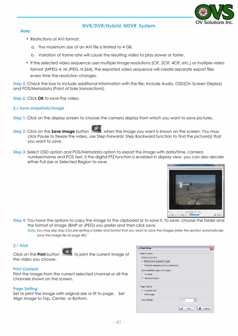
2.6 Save snapshots/Image
Step 1: Click on the display screen to choose the camera display from which you want to save pictures.
Step 2: Click on the Save Image button when the image you want is shown on the screen. You may
click Pause to freeze the video, use Step Forward/ Step Backward function to find the picture(s) that
you want to save. Step 3: Select OSD option and POS/Metadata option to export the image with date/time, camera
number/name and POS text. If the digital PTZ function is enabled in display view, you can also decide
either Full size or Selected Region to save.
Step 4: You have the options to copy the image to the clipboard or to save it. To save; choose the folder and
the format of image (BMP or JPEG) you prefer and then click save.
Note: You may skip step 3 by pre-setting a folder and format that you want to save the images (refer the section automatically
save the image file at page 48.)
2.7 Print
Click on the Print button to print the current image of
the video you choose.
Print Content:
Print the image from the current selected channel or all the
channels shown on the screen.
Page Setting:
Set to print the image with original size or fit to page. Set
Align image to Top, Center, or Bottom.
NVR/DVR/Hybrid NDVR System
- 42 -
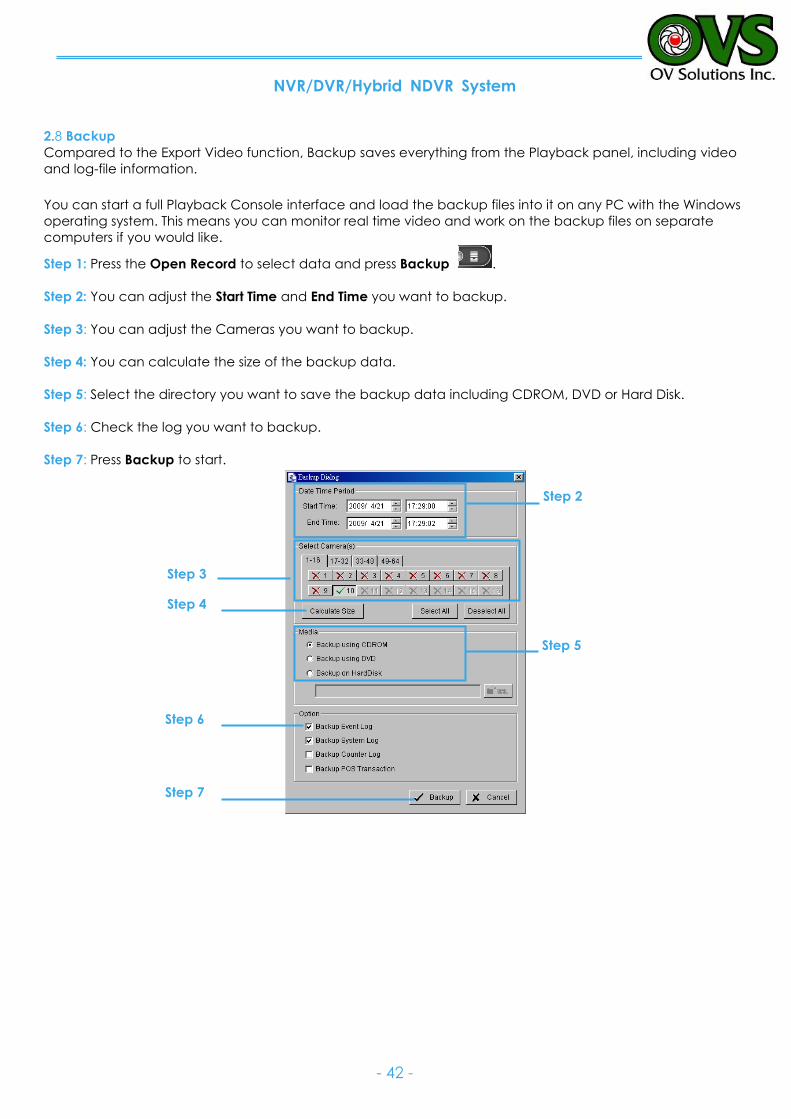
2.8 Backup
Compared to the Export Video function, Backup saves everything from the Playback panel, including video
and log-file information.
You can start a full Playback Console interface and load the backup files into it on any PC with the Windows
operating system. This means you can monitor real time video and work on the backup files on separate
computers if you would like.
Step 1: Press the Open Record to select data and press Backup .
Step 2: You can adjust the Start Time and End Time you want to backup.
Step 3: You can adjust the Cameras you want to backup.
Step 4: You can calculate the size of the backup data.
Step 5: Select the directory you want to save the backup data including CDROM, DVD or Hard Disk.
Step 6: Check the log you want to backup.
Step 7: Press Backup to start.
Step 2
Step 3
Step 4
Step 5
Step 6
Step 7
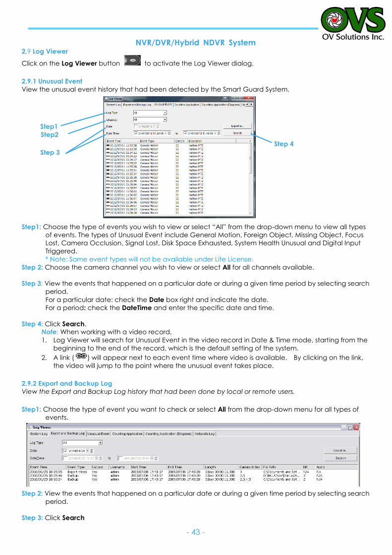
NVR/DVR/Hybrid NDVR System
- 43 -
2.9 Log Viewer
Click on the Log Viewer button to activate the Log Viewer dialog.
2.9.1 Unusual Event
View the unusual event history that had been detected by the Smart Guard System.
Step1
Step2
Step 3
Step1: Choose the type of events you wish to view or select “All” from the drop-down menu to view all types
of events. The types of Unusual Event include General Motion, Foreign Object, Missing Object, Focus
Lost, Camera Occlusion, Signal Lost, Disk Space Exhausted, System Health Unusual and Digital Input
Triggered.
* Note: Some event types will not be available under Lite License.
Step 2: Choose the camera channel you wish to view or select All for all channels available.
Step 3: View the events that happened on a particular date or during a given time period by selecting search
period.
For a particular date: check the Date box right and indicate the date.
For a period: check the DateTime and enter the specific date and time.
Step 4: Click Search.
Note: When working with a video record,
1. Log Viewer will search for Unusual Event in the video record in Date & Time mode, starting from the
beginning to the end of the record, which is the default setting of the system.
2. A link ( ) will appear next to each event time where video is available. By clicking on the link,
the video will jump to the point where the unusual event takes place.
2.9.2 Export and Backup Log
View the Export and Backup Log history that had been done by local or remote users.
Step1: Choose the type of event you want to check or select All from the drop-down menu for all types of
events.
Step 2: View the events that happened on a particular date or during a given time period by selecting search
period.
Step 3: Click Search
Step 4
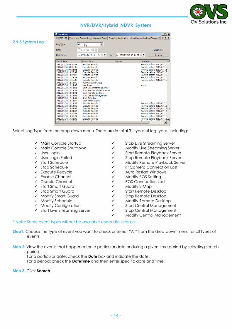
NVR/DVR/Hybrid NDVR System
- 44 -
2.9.3 System Log
Select Log Type from the drop-down menu. There are in total 31 types of log types, including:
* Note: Some event types will not be available under Lite License.
Step1: Choose the type of event you want to check or select “All” from the drop-down menu for all types of
events.
Step 2: View the events that happened on a particular date or during a given time period by selecting search
period.
For a particular date: check the Date box and indicate the date.
For a period: check the DateTime and then enter specific date and time.
Step 3: Click Search.
Main Console Startup
Main Console Shutdown
User Login
User Login Failed
Start Schedule
Stop Schedule
Execute Recycle
Enable Channel
Disable Channel
Start Smart Guard
Stop Smart Guard
Modify Smart Guard
Modify Schedule
Modify Configuration
Start Live Streaming Server
Stop Live Streaming Server
Modify Live Streaming Server
Start Remote Playback Server
Stop Remote Playback Server
Modify Remote Playback Server
IP Camera Connection Lost
Auto Restart Windows
Modify POS Setting
POS Connection Lost
Modify E-Map
Start Remote Desktop
Stop Remote Desktop
Modify Remote Desktop
Start Central Management
Stop Central Management
Modify Central Management
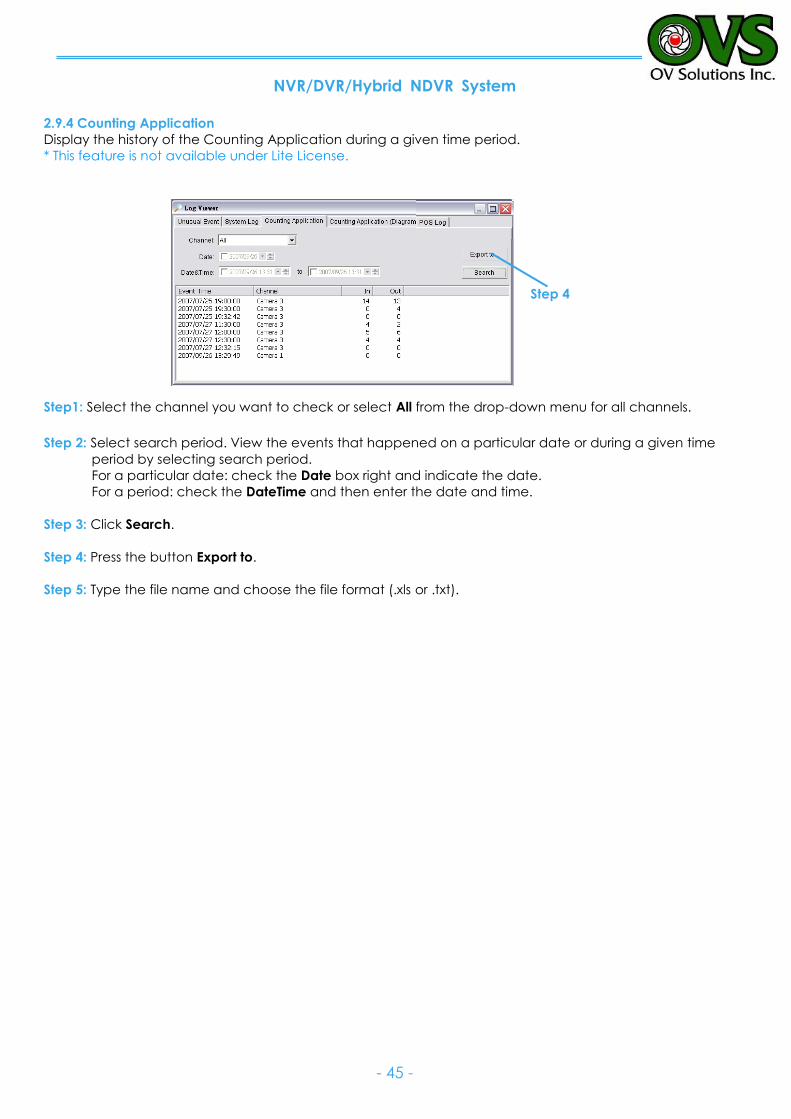
NVR/DVR/Hybrid NDVR System
- 45 -
2.9.4 Counting Application
Display the history of the Counting Application during a given time period.
* This feature is not available under Lite License.
Step1: Select the channel you want to check or select All from the drop-down menu for all channels.
Step 2: Select search period. View the events that happened on a particular date or during a given time
period by selecting search period.
For a particular date: check the Date box right and indicate the date.
For a period: check the DateTime and then enter the date and time.
Step 3: Click Search.
Step 4: Press the button Export to.
Step 5: Type the file name and choose the file format (.xls or .txt).
Step 4
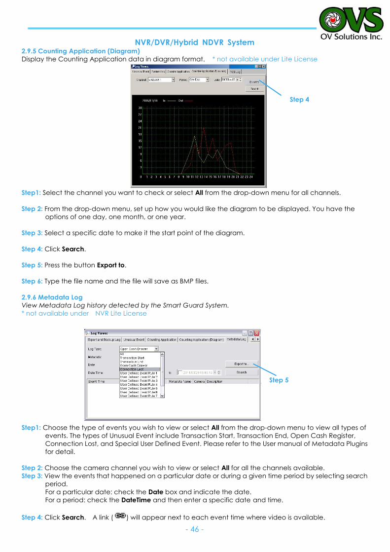
NVR/DVR/Hybrid NDVR System
- 46 -
2.9.5 Counting Application (Diagram)
Display the Counting Application data in diagram format. * not available under Lite License
Step1: Select the channel you want to check or select All from the drop-down menu for all channels.
Step 2: From the drop-down menu, set up how you would like the diagram to be displayed. You have the
options of one day, one month, or one year.
Step 3: Select a specific date to make it the start point of the diagram.
Step 4: Click Search.
Step 5: Press the button Export to.
Step 6: Type the file name and the file will save as BMP files.
2.9.6 Metadata Log
View Metadata Log history detected by the Smart Guard System.
* not available under NVR Lite License
Step1: Choose the type of events you wish to view or select All from the drop-down menu to view all types of
events. The types of Unusual Event include Transaction Start, Transaction End, Open Cash Register,
Connection Lost, and Special User Defined Event. Please refer to the User manual of Metadata Plugins
for detail.
Step 2: Choose the camera channel you wish to view or select All for all the channels available.
Step 3: View the events that happened on a particular date or during a given time period by selecting search
period.
For a particular date: check the Date box and indicate the date.
For a period: check the DateTime and then enter a specific date and time.
Step 4: Click Search. A link ( ) will appear next to each event time where video is available.
Step 4
Step 5
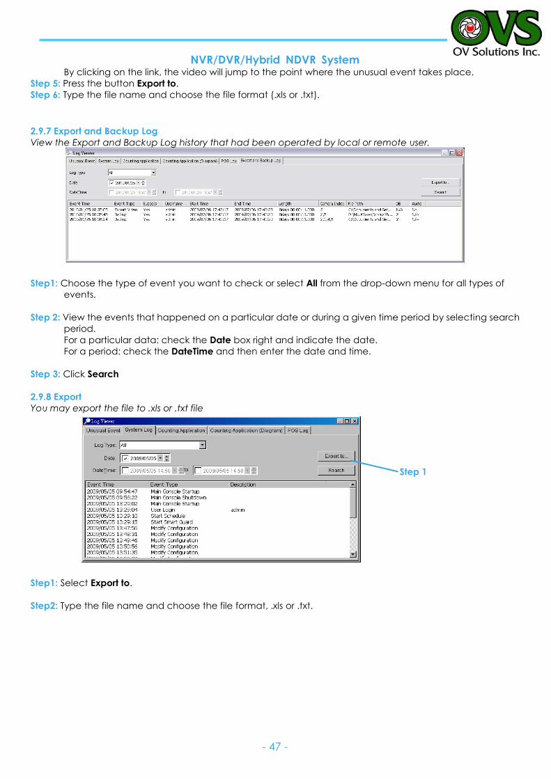
NVR/DVR/Hybrid NDVR System
- 47 -
By clicking on the link, the video will jump to the point where the unusual event takes place.
Step 5: Press the button Export to.
Step 6: Type the file name and choose the file format (.xls or .txt).
2.9.7 Export and Backup Log
View the Export and Backup Log history that had been operated by local or remote user.
Step1: Choose the type of event you want to check or select All from the drop-down menu for all types of
events.
Step 2: View the events that happened on a particular date or during a given time period by selecting search
period.
For a particular data: check the Date box right and indicate the date.
For a period: check the DateTime and then enter the date and time.
Step 3: Click Search
2.9.8 Export
You may export the file to .xls or .txt file
Step1: Select Export to.
Step2: Type the file name and choose the file format, .xls or .txt.
Step 1
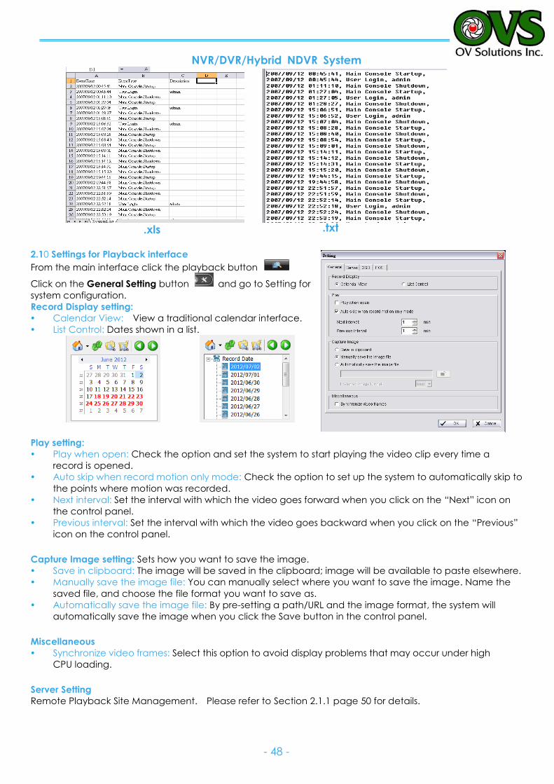
NVR/DVR/Hybrid NDVR System
- 48 -
2.10 Settings for Playback interface
From the main interface click the playback button
Click on the General Setting button and go to Setting for
system configuration.
Record Display setting:
Calendar View: View a traditional calendar interface.
List Control: Dates shown in a list.
Play setting:
Play when open: Check the option and set the system to start playing the video clip every time a
record is opened.
Auto skip when record motion only mode: Check the option to set up the system to automatically skip to
the points where motion was recorded.
Next interval: Set the interval with which the video goes forward when you click on the “Next” icon on
the control panel.
Previous interval: Set the interval with which the video goes backward when you click on the “Previous”
icon on the control panel.
Capture Image setting: Sets how you want to save the image.
Save in clipboard: The image will be saved in the clipboard; image will be available to paste elsewhere.
Manually save the image file: You can manually select where you want to save the image. Name the
saved file, and choose the file format you want to save as.
Automatically save the image file: By pre-setting a path/URL and the image format, the system will
automatically save the image when you click the Save button in the control panel.
Miscellaneous
Synchronize video frames: Select this option to avoid display problems that may occur under high
CPU loading.
Server Setting
Remote Playback Site Management. Please refer to Section 2.1.1 page 50 for details.
.xls .txt
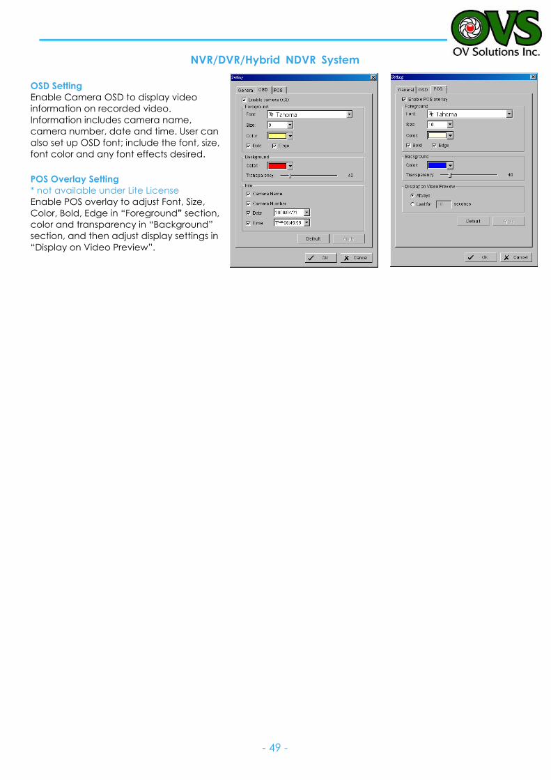
NVR/DVR/Hybrid NDVR System
- 49 -
OSD Setting
Enable Camera OSD to display video
information on recorded video.
Information includes camera name,
camera number, date and time. User can
also set up OSD font; include the font, size,
font color and any font effects desired.
POS Overlay Setting
* not available under Lite License
Enable POS overlay to adjust Font, Size,
Color, Bold, Edge in “Foreground” section,
color and transparency in “Background”
section, and then adjust display settings in
“Display on Video Preview”.
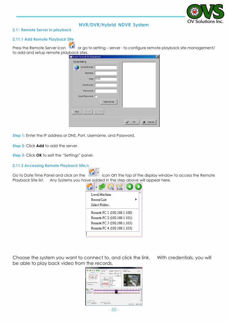
NVR/DVR/Hybrid NDVR System
- 50 -
2.11 Remote Server in playback
2.11.1 Add Remote Playback Site
Press the Remote Server Icon or go to setting – server - to configure remote playback site management/
to add and setup remote playback sites.
Step 1: Enter the IP address or DNS, Port, Username, and Password.
Step 2: Click Add to add the server.
Step 3: Click OK to exit the “Settings” panel.
2.11.2 Accessing Remote Playback Site/s
Go to Date Time Panel and click on the icon on the top of the display window to access the Remote
Playback Site list. Any Systems you have added in the step above will appear here.
Choose the system you want to connect to, and click the link. With credentials, you will
be able to play back video from the records.
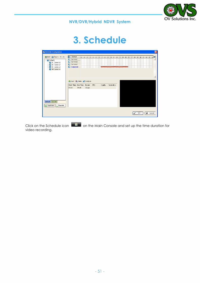
NVR/DVR/Hybrid NDVR System
- 51 -
3. Schedule
Click on the Schedule icon on the Main Console and set up the time duration for
video recording.
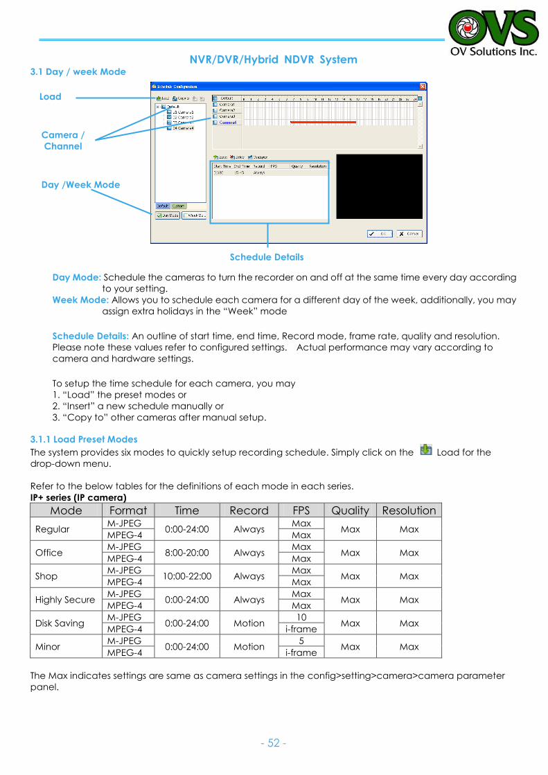
NVR/DVR/Hybrid NDVR System
- 52 -
3.1 Day / week Mode
Load
Camera /
Channel
Day /Week Mode
Day Mode: Schedule the cameras to turn the recorder on and off at the same time every day according
to your setting.
Week Mode: Allows you to schedule each camera for a different day of the week, additionally, you may
assign extra holidays in the “Week” mode
Schedule Details: An outline of start time, end time, Record mode, frame rate, quality and resolution.
Please note these values refer to configured settings. Actual performance may vary according to
camera and hardware settings.
To setup the time schedule for each camera, you may
1. “Load” the preset modes or
2. “Insert” a new schedule manually or
3. “Copy to” other cameras after manual setup.
3.1.1 Load Preset Modes
The system provides six modes to quickly setup recording schedule. Simply click on the Load for the
drop-down menu.
Refer to the below tables for the definitions of each mode in each series.
IP+ series (IP camera)
Mode Format Time Record FPS Quality Resolution
Regular M-JPEG
0:00-24:00 Always Max
Max Max MPEG-4 Max
Office M-JPEG
8:00-20:00 Always Max
Max Max MPEG-4 Max
Shop M-JPEG
10:00-22:00 Always Max
Max Max MPEG-4 Max
Highly Secure M-JPEG
0:00-24:00 Always Max
Max Max MPEG-4 Max
Disk Saving M-JPEG
0:00-24:00 Motion 10
Max Max MPEG-4 i-frame
Minor M-JPEG
0:00-24:00 Motion 5
Max Max MPEG-4 i-frame
The Max indicates settings are same as camera settings in the config>setting>camera>camera parameter
panel.
Schedule Details
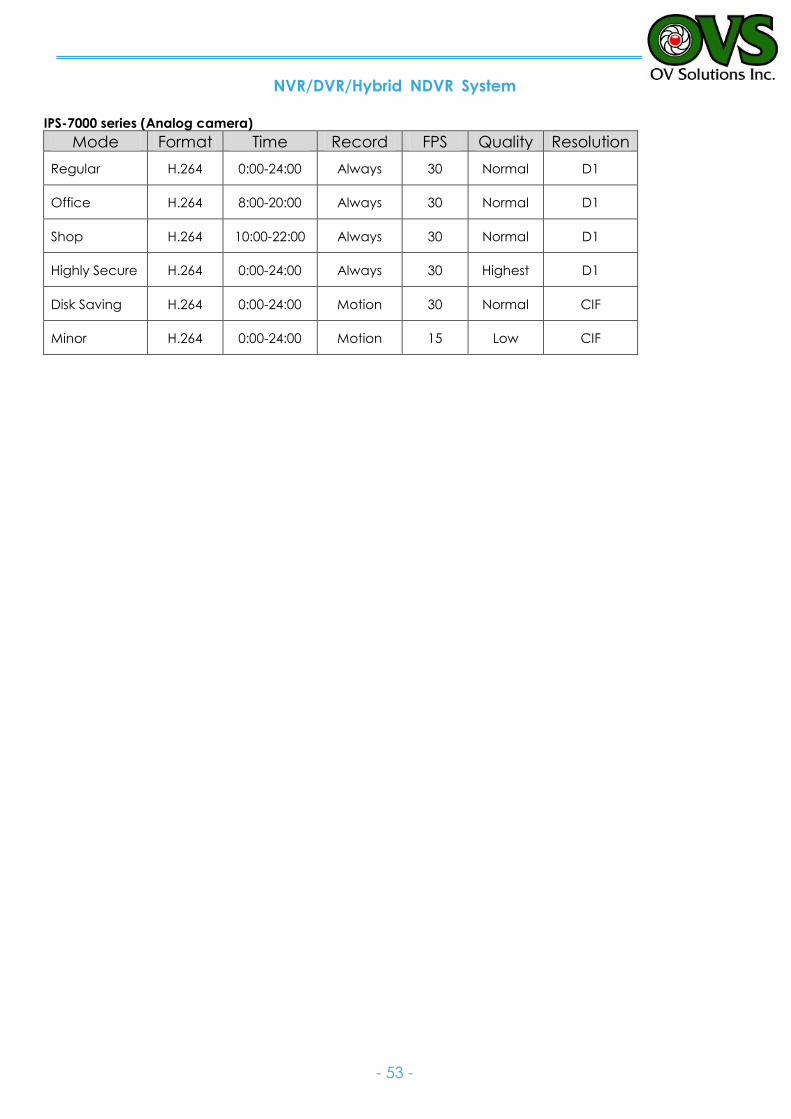
NVR/DVR/Hybrid NDVR System
- 53 -
IPS-7000 series (Analog camera)
Mode Format Time Record FPS Quality Resolution
Regular H.264 0:00-24:00 Always 30 Normal D1
Office H.264 8:00-20:00 Always 30 Normal D1
Shop H.264 10:00-22:00 Always 30 Normal D1
Highly Secure H.264 0:00-24:00 Always 30 Highest D1
Disk Saving H.264 0:00-24:00 Motion 30 Normal CIF
Minor H.264 0:00-24:00 Motion 15 Low CIF
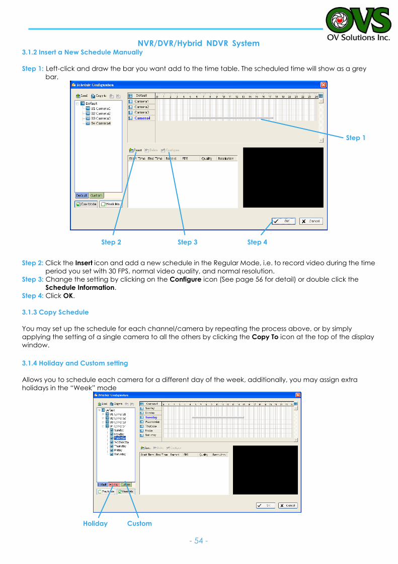
NVR/DVR/Hybrid NDVR System
- 54 -
3.1.2 Insert a New Schedule Manually
Step 1: Left-click and draw the bar you want add to the time table. The scheduled time will show as a grey
bar.
Step 2: Click the Insert icon and add a new schedule in the Regular Mode, i.e. to record video during the time
period you set with 30 FPS, normal video quality, and normal resolution.
Step 3: Change the setting by clicking on the Configure icon (See page 56 for detail) or double click the
Schedule Information.
Step 4: Click OK.
3.1.3 Copy Schedule
You may set up the schedule for each channel/camera by repeating the process above, or by simply
applying the setting of a single camera to all the others by clicking the Copy To icon at the top of the display
window.
3.1.4 Holiday and Custom setting
Allows you to schedule each camera for a different day of the week, additionally, you may assign extra
holidays in the “Week” mode
Step 1
Step 2 Step 3 Step 4
Holiday Custom
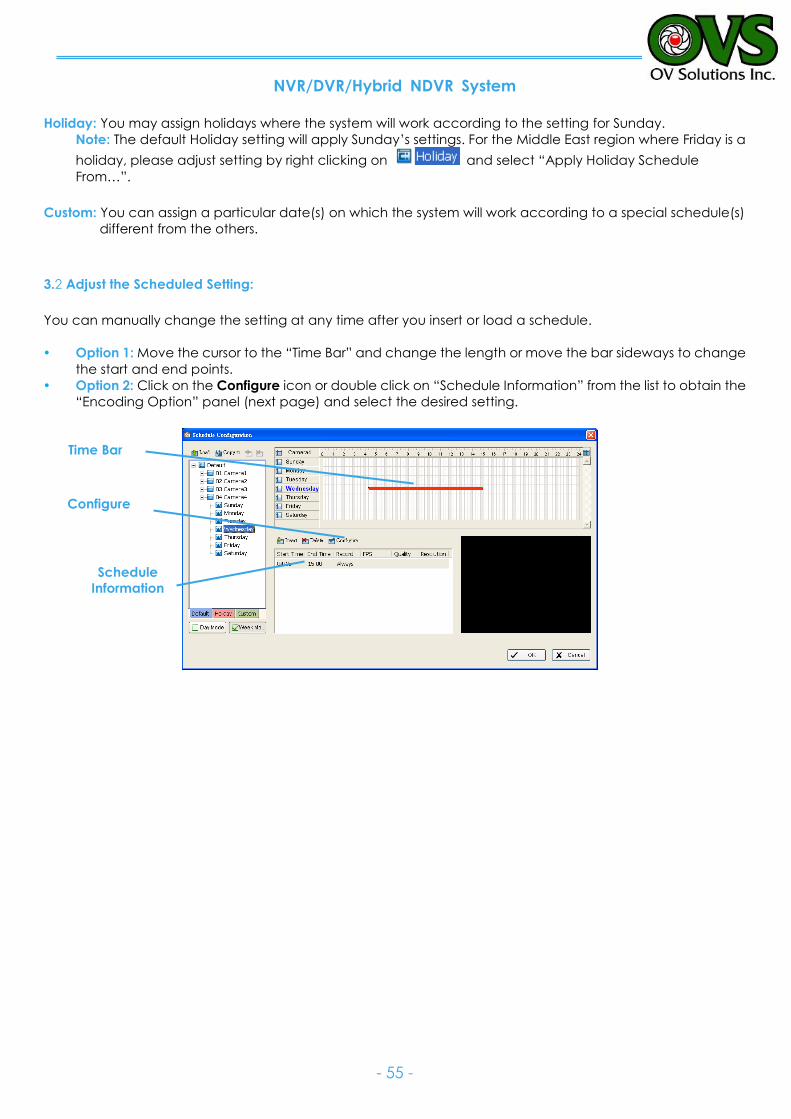
NVR/DVR/Hybrid NDVR System
- 55 -
Holiday: You may assign holidays where the system will work according to the setting for Sunday.
Note: The default Holiday setting will apply Sunday’s settings. For the Middle East region where Friday is a
holiday, please adjust setting by right clicking on and select “Apply Holiday Schedule
From…”.
Custom: You can assign a particular date(s) on which the system will work according to a special schedule(s)
different from the others.
3.2 Adjust the Scheduled Setting:
You can manually change the setting at any time after you insert or load a schedule.
Option 1: Move the cursor to the “Time Bar” and change the length or move the bar sideways to change
the start and end points.
Option 2: Click on the Configure icon or double click on “Schedule Information” from the list to obtain the
“Encoding Option” panel (next page) and select the desired setting.
Time Bar
Configure
Schedule
Information
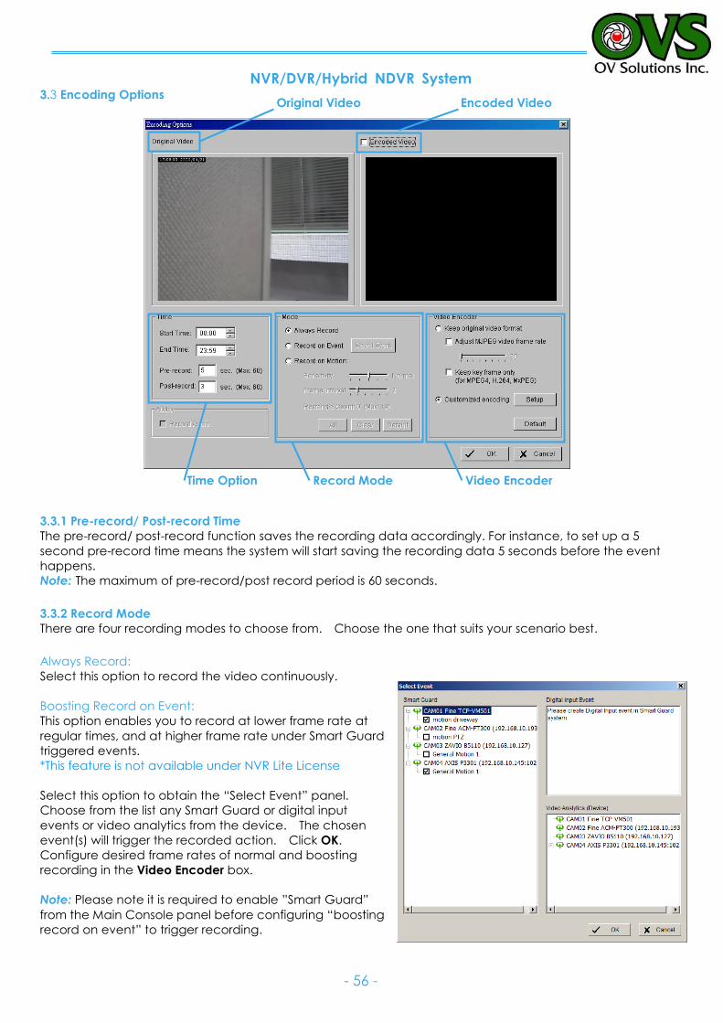
NVR/DVR/Hybrid NDVR System
- 56 -
3.3 Encoding Options
3.3.1 Pre-record/ Post-record Time
The pre-record/ post-record function saves the recording data accordingly. For instance, to set up a 5
second pre-record time means the system will start saving the recording data 5 seconds before the event
happens.
Note: The maximum of pre-record/post record period is 60 seconds.
3.3.2 Record Mode
There are four recording modes to choose from. Choose the one that suits your scenario best.
Always Record:
Select this option to record the video continuously.
Boosting Record on Event:
This option enables you to record at lower frame rate at
regular times, and at higher frame rate under Smart Guard
triggered events.
*This feature is not available under NVR Lite License
Select this option to obtain the “Select Event” panel.
Choose from the list any Smart Guard or digital input
events or video analytics from the device. The chosen
event(s) will trigger the recorded action. Click OK.
Configure desired frame rates of normal and boosting
recording in the Video Encoder box.
Note: Please note it is required to enable ”Smart Guard”
from the Main Console panel before configuring “boosting
record on event” to trigger recording.
Original Video Encoded Video
Video Encoder Record Mode Time Option
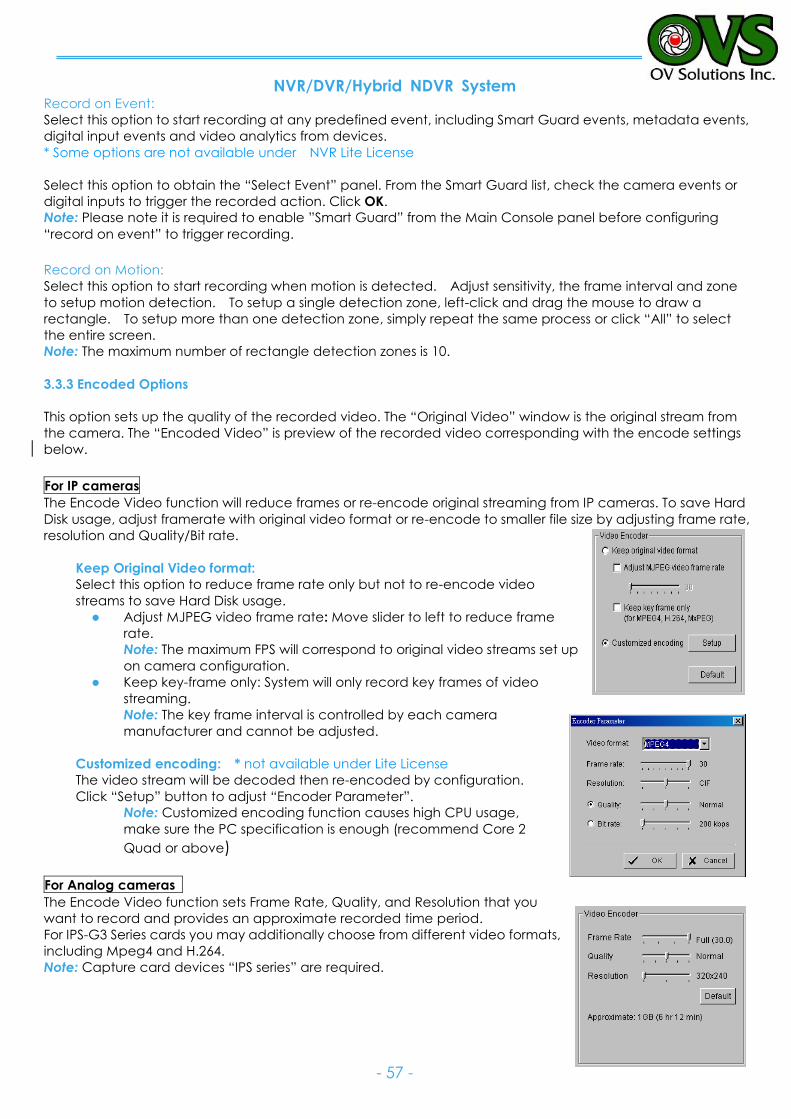
NVR/DVR/Hybrid NDVR System
- 57 -
Record on Event:
Select this option to start recording at any predefined event, including Smart Guard events, metadata events,
digital input events and video analytics from devices.
* Some options are not available under NVR Lite License
Select this option to obtain the “Select Event” panel. From the Smart Guard list, check the camera events or
digital inputs to trigger the recorded action. Click OK.
Note: Please note it is required to enable ”Smart Guard” from the Main Console panel before configuring
“record on event” to trigger recording. Record on Motion:
Select this option to start recording when motion is detected. Adjust sensitivity, the frame interval and zone
to setup motion detection. To setup a single detection zone, left-click and drag the mouse to draw a
rectangle. To setup more than one detection zone, simply repeat the same process or click “All” to select
the entire screen.
Note: The maximum number of rectangle detection zones is 10.
3.3.3 Encoded Options
This option sets up the quality of the recorded video. The “Original Video” window is the original stream from
the camera. The “Encoded Video” is preview of the recorded video corresponding with the encode settings
below.
For IP cameras
The Encode Video function will reduce frames or re-encode original streaming from IP cameras. To save Hard
Disk usage, adjust framerate with original video format or re-encode to smaller file size by adjusting frame rate,
resolution and Quality/Bit rate.
Keep Original Video format:
Select this option to reduce frame rate only but not to re-encode video
streams to save Hard Disk usage.
Adjust MJPEG video frame rate: Move slider to left to reduce frame
rate.
Note: The maximum FPS will correspond to original video streams set up
on camera configuration.
Keep key-frame only: System will only record key frames of video
streaming.
Note: The key frame interval is controlled by each camera
manufacturer and cannot be adjusted.
Customized encoding: * not available under Lite License
The video stream will be decoded then re-encoded by configuration.
Click “Setup” button to adjust “Encoder Parameter”.
Note: Customized encoding function causes high CPU usage, make sure the PC specification is enough (recommend Core 2 Quad or above)
For Analog cameras
The Encode Video function sets Frame Rate, Quality, and Resolution that you
want to record and provides an approximate recorded time period.
For IPS-G3 Series cards you may additionally choose from different video formats,
including Mpeg4 and H.264.
Note: Capture card devices “IPS series” are required.
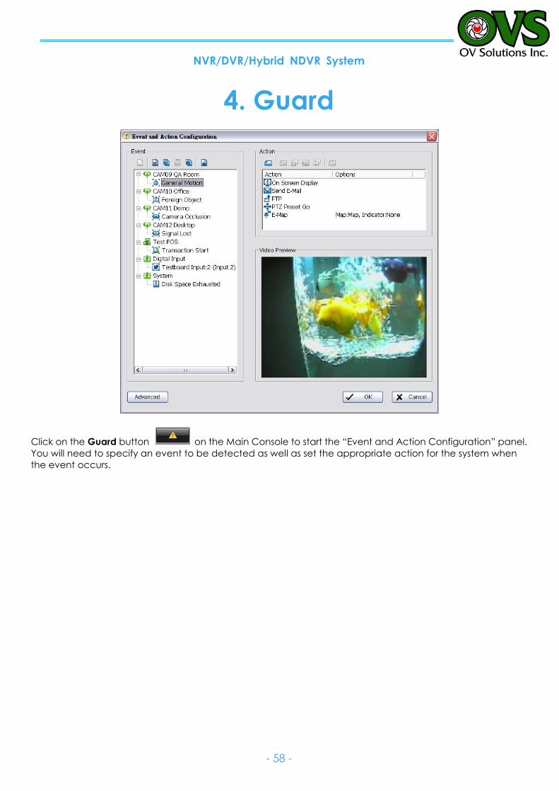
NVR/DVR/Hybrid NDVR System
- 58 -
4. Guard
Click on the Guard button on the Main Console to start the “Event and Action Configuration” panel.
You will need to specify an event to be detected as well as set the appropriate action for the system when
the event occurs.
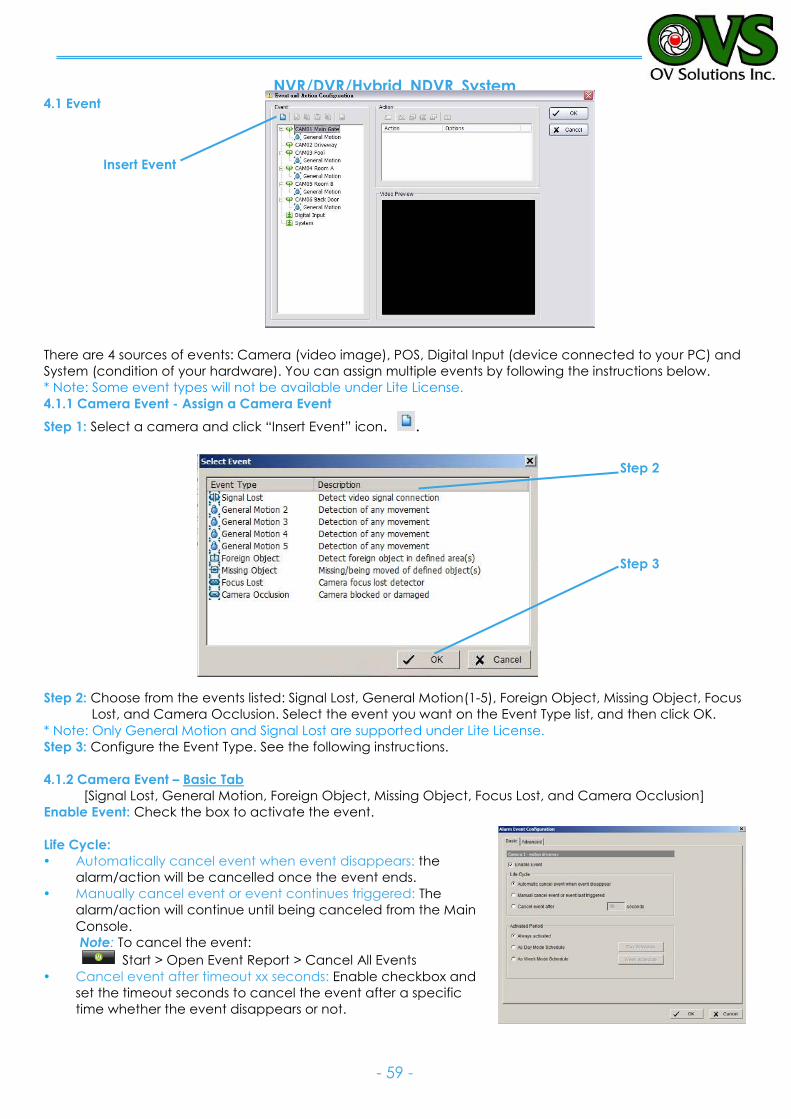
NVR/DVR/Hybrid NDVR System
- 59 -
4.1 Event
There are 4 sources of events: Camera (video image), POS, Digital Input (device connected to your PC) and
System (condition of your hardware). You can assign multiple events by following the instructions below.
* Note: Some event types will not be available under Lite License. 4.1.1 Camera Event - Assign a Camera Event
Step 1: Select a camera and click “Insert Event” icon. .
Step 2: Choose from the events listed: Signal Lost, General Motion(1-5), Foreign Object, Missing Object, Focus
Lost, and Camera Occlusion. Select the event you want on the Event Type list, and then click OK.
* Note: Only General Motion and Signal Lost are supported under Lite License. Step 3: Configure the Event Type. See the following instructions.
4.1.2 Camera Event – Basic Tab
[Signal Lost, General Motion, Foreign Object, Missing Object, Focus Lost, and Camera Occlusion] Enable Event: Check the box to activate the event.
Life Cycle:
Automatically cancel event when event disappears: the
alarm/action will be cancelled once the event ends.
Manually cancel event or event continues triggered: The
alarm/action will continue until being canceled from the Main
Console.
Note: To cancel the event:
Start > Open Event Report > Cancel All Events
Cancel event after timeout xx seconds: Enable checkbox and
set the timeout seconds to cancel the event after a specific
time whether the event disappears or not.
Insert Event
Step 2
Step 3
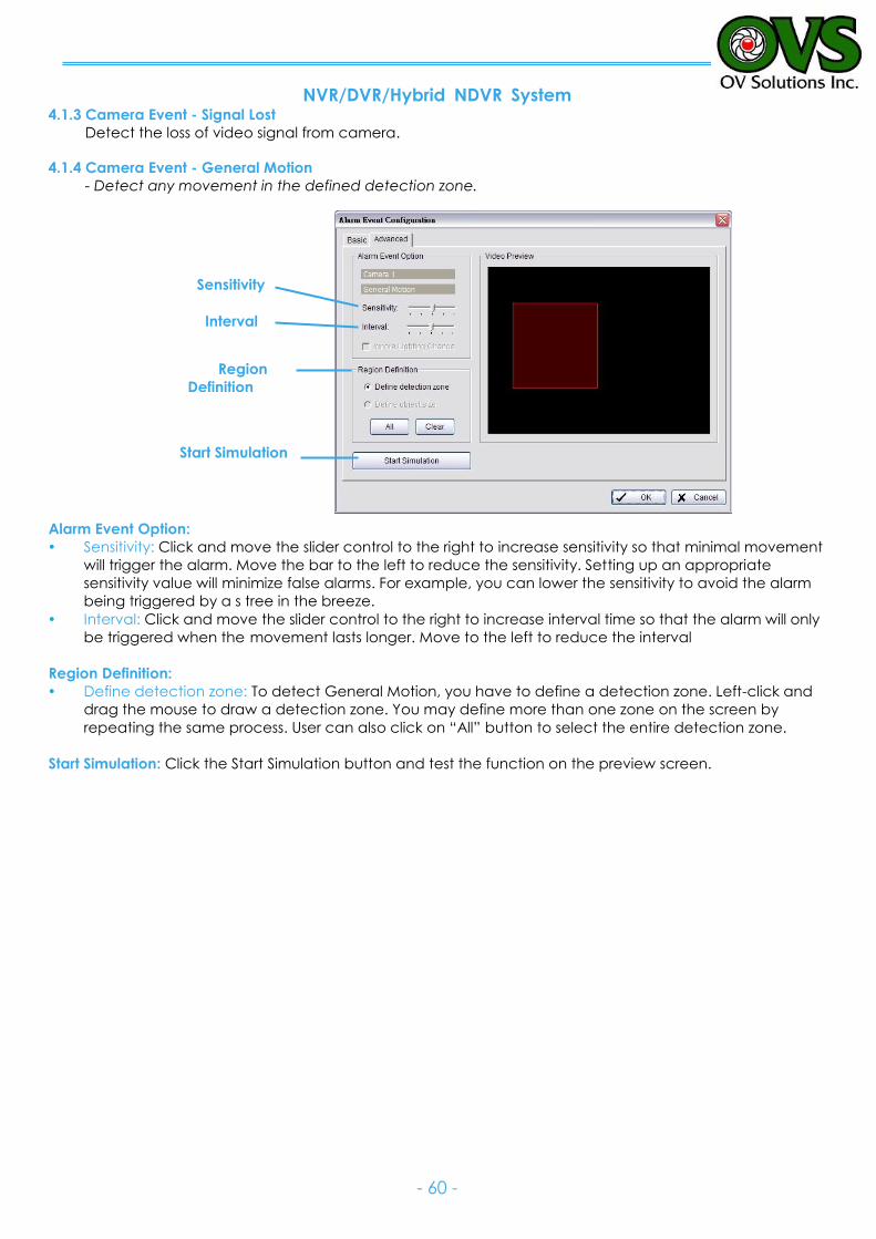
NVR/DVR/Hybrid NDVR System
- 60 -
4.1.3 Camera Event - Signal Lost
Detect the loss of video signal from camera.
4.1.4 Camera Event - General Motion
- Detect any movement in the defined detection zone.
Alarm Event Option:
Sensitivity: Click and move the slider control to the right to increase sensitivity so that minimal movement
will trigger the alarm. Move the bar to the left to reduce the sensitivity. Setting up an appropriate
sensitivity value will minimize false alarms. For example, you can lower the sensitivity to avoid the alarm
being triggered by a s tree in the breeze.
Interval: Click and move the slider control to the right to increase interval time so that the alarm will only
be triggered when the movement lasts longer. Move to the left to reduce the interval
Region Definition:
Define detection zone: To detect General Motion, you have to define a detection zone. Left-click and
drag the mouse to draw a detection zone. You may define more than one zone on the screen by
repeating the same process. User can also click on “All” button to select the entire detection zone.
Start Simulation: Click the Start Simulation button and test the function on the preview screen.
Sensitivity
Interval
Region
Definition
Start Simulation
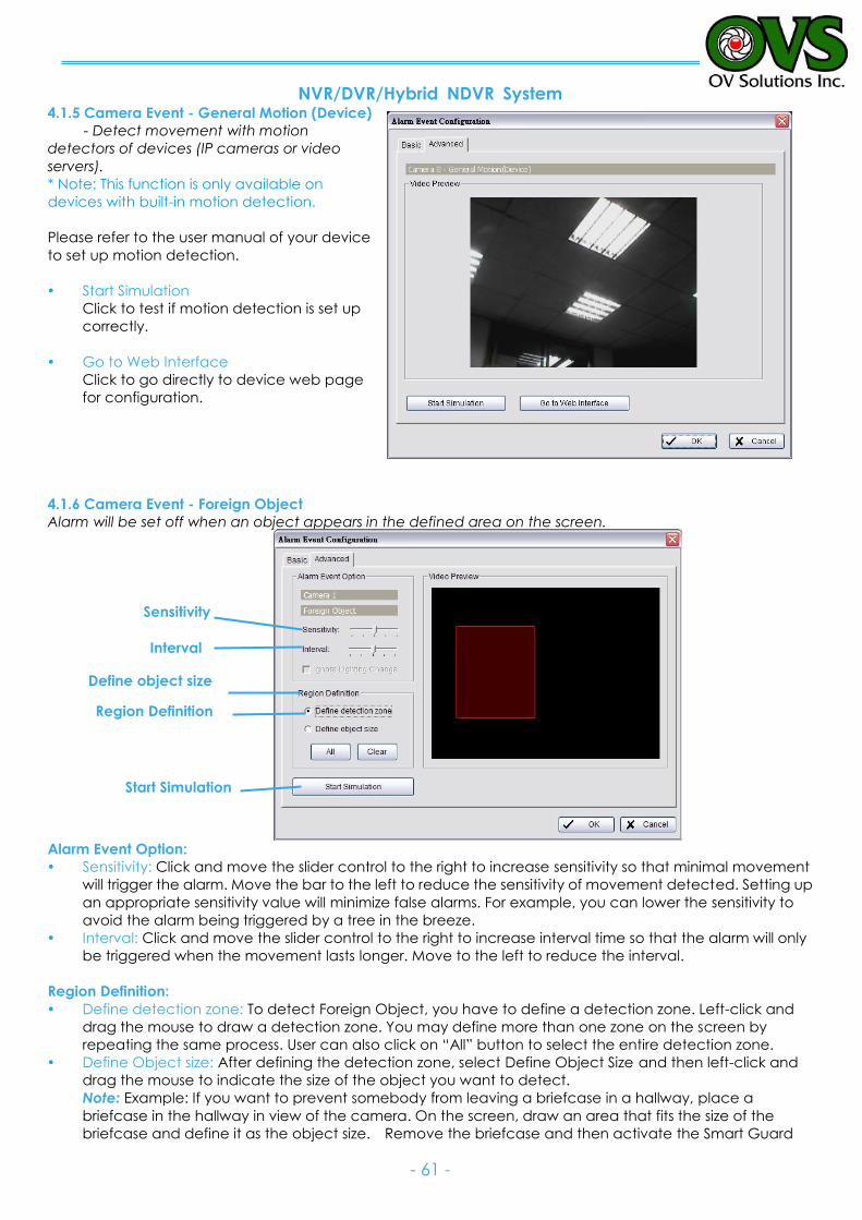
NVR/DVR/Hybrid NDVR System
- 61 -
4.1.5 Camera Event - General Motion (Device)
- Detect movement with motion
detectors of devices (IP cameras or video
servers).
* Note: This function is only available on
devices with built-in motion detection.
Please refer to the user manual of your device
to set up motion detection.
Start Simulation
Click to test if motion detection is set up
correctly.
Go to Web Interface
Click to go directly to device web page
for configuration.
4.1.6 Camera Event - Foreign Object
Alarm will be set off when an object appears in the defined area on the screen.
Alarm Event Option:
Sensitivity: Click and move the slider control to the right to increase sensitivity so that minimal movement
will trigger the alarm. Move the bar to the left to reduce the sensitivity of movement detected. Setting up
an appropriate sensitivity value will minimize false alarms. For example, you can lower the sensitivity to
avoid the alarm being triggered by a tree in the breeze.
Interval: Click and move the slider control to the right to increase interval time so that the alarm will only
be triggered when the movement lasts longer. Move to the left to reduce the interval.
Region Definition:
Define detection zone: To detect Foreign Object, you have to define a detection zone. Left-click and
drag the mouse to draw a detection zone. You may define more than one zone on the screen by
repeating the same process. User can also click on “All” button to select the entire detection zone.
Define Object size: After defining the detection zone, select Define Object Size and then left-click and
drag the mouse to indicate the size of the object you want to detect.
Note: Example: If you want to prevent somebody from leaving a briefcase in a hallway, place a
briefcase in the hallway in view of the camera. On the screen, draw an area that fits the size of the
briefcase and define it as the object size. Remove the briefcase and then activate the Smart Guard
Sensitivity
Interval
Region Definition
Define object size
Start Simulation
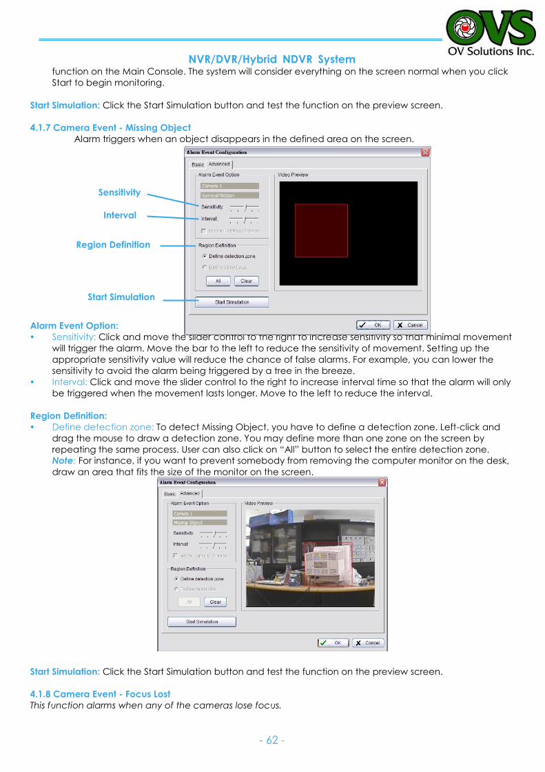
NVR/DVR/Hybrid NDVR System
- 62 -
function on the Main Console. The system will consider everything on the screen normal when you click
Start to begin monitoring.
Start Simulation: Click the Start Simulation button and test the function on the preview screen.
4.1.7 Camera Event - Missing Object
Alarm triggers when an object disappears in the defined area on the screen.
Alarm Event Option:
Sensitivity: Click and move the slider control to the right to increase sensitivity so that minimal movement
will trigger the alarm. Move the bar to the left to reduce the sensitivity of movement. Setting up the
appropriate sensitivity value will reduce the chance of false alarms. For example, you can lower the
sensitivity to avoid the alarm being triggered by a tree in the breeze.
Interval: Click and move the slider control to the right to increase interval time so that the alarm will only
be triggered when the movement lasts longer. Move to the left to reduce the interval.
Region Definition:
Define detection zone: To detect Missing Object, you have to define a detection zone. Left-click and
drag the mouse to draw a detection zone. You may define more than one zone on the screen by
repeating the same process. User can also click on “All” button to select the entire detection zone.
Note: For instance, if you want to prevent somebody from removing the computer monitor on the desk,
draw an area that fits the size of the monitor on the screen.
Start Simulation: Click the Start Simulation button and test the function on the preview screen.
4.1.8 Camera Event - Focus Lost
This function alarms when any of the cameras lose focus.
Sensitivity
Interval
Region Definition
Start Simulation

NVR/DVR/Hybrid NDVR System
- 63 -
Alarm Event Option:
Sensitivity: Click and move the slider control to the right to increase sensitivity so that a relatively small
movement will trigger the alarm. Move the bar to the left to reduce the sensitivity of movement
detection. Set up an appropriate Sensitivity value will reduce the chance of false alarm. For example,
you can lower the Sensitivity to avoid the alarm being triggered by a tree in the breeze.
Interval: Click and move the slider control to the right to increase interval time so that the alarm will only
be triggered when the movement lasts longer. Move to the left to reduce the interval time.
Ignore Lighting: Check the box to avoid alarm being set off by light changing.
Region Definition:
Define detection zone: To detect Lose Focus, you have to define a detection zone. Left-click and drag
the mouse to draw a detection zone. You may define more than one zone on the screen by repeating
the same process. User can also click on “All” button to select the entire detection zone.
Start Simulation: Click the Start Simulation button and test the function on the preview screen.
4.1.9 Camera Event - Camera Occlusion
This function alarms you when any of the cameras are blocked.
Sensitivity
Interval
Ignore Lighting
Start Simulation
Sensitivity
Interval
Ignore Lighting
Start Simulation
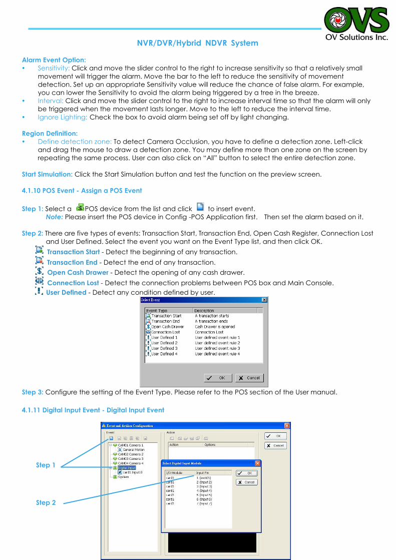
NVR/DVR/Hybrid NDVR System
- 64 -
Alarm Event Option:
Sensitivity: Click and move the slider control to the right to increase sensitivity so that a relatively small
movement will trigger the alarm. Move the bar to the left to reduce the sensitivity of movement
detection. Set up an appropriate Sensitivity value will reduce the chance of false alarm. For example,
you can lower the Sensitivity to avoid the alarm being triggered by a tree in the breeze.
Interval: Click and move the slider control to the right to increase interval time so that the alarm will only
be triggered when the movement lasts longer. Move to the left to reduce the interval time.
Ignore Lighting: Check the box to avoid alarm being set off by light changing.
Region Definition:
Define detection zone: To detect Camera Occlusion, you have to define a detection zone. Left-click
and drag the mouse to draw a detection zone. You may define more than one zone on the screen by
repeating the same process. User can also click on “All” button to select the entire detection zone.
Start Simulation: Click the Start Simulation button and test the function on the preview screen.
4.1.10 POS Event - Assign a POS Event
Step 1: Select a POS device from the list and click to insert event.
Note: Please insert the POS device in Config -POS Application first. Then set the alarm based on it.
Step 2: There are five types of events: Transaction Start, Transaction End, Open Cash Register, Connection Lost
and User Defined. Select the event you want on the Event Type list, and then click OK.
Transaction Start - Detect the beginning of any transaction.
Transaction End - Detect the end of any transaction.
Open Cash Drawer - Detect the opening of any cash drawer.
Connection Lost - Detect the connection problems between POS box and Main Console.
User Defined - Detect any condition defined by user.
Step 3: Configure the setting of the Event Type. Please refer to the POS section of the User manual.
4.1.11 Digital Input Event - Digital Input Event
Step 1
Step 2
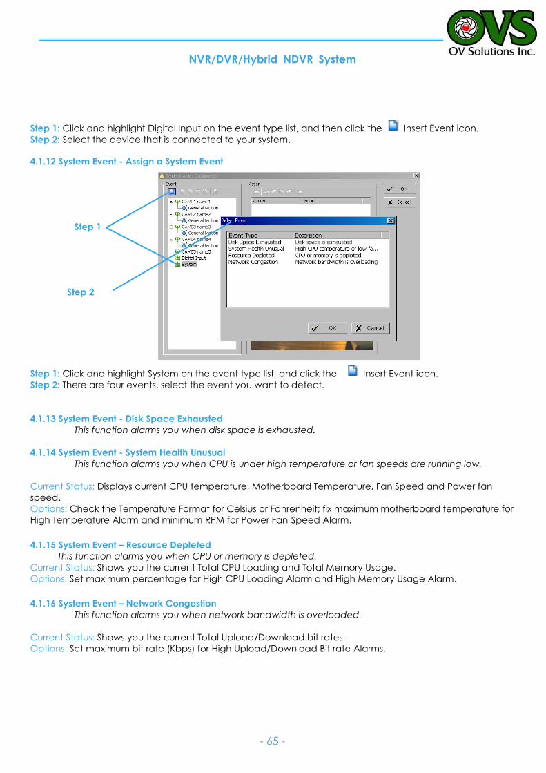
NVR/DVR/Hybrid NDVR System
- 65 -
Step 1: Click and highlight Digital Input on the event type list, and then click the Insert Event icon.
Step 2: Select the device that is connected to your system.
4.1.12 System Event - Assign a System Event
Step 1
Step 2
Step 1: Click and highlight System on the event type list, and click the Insert Event icon.
Step 2: There are four events, select the event you want to detect.
4.1.13 System Event - Disk Space Exhausted
This function alarms you when disk space is exhausted.
4.1.14 System Event - System Health Unusual
This function alarms you when CPU is under high temperature or fan speeds are running low.
Current Status: Displays current CPU temperature, Motherboard Temperature, Fan Speed and Power fan
speed.
Options: Check the Temperature Format for Celsius or Fahrenheit; fix maximum motherboard temperature for
High Temperature Alarm and minimum RPM for Power Fan Speed Alarm.
4.1.15 System Event – Resource Depleted
This function alarms you when CPU or memory is depleted.
Current Status: Shows you the current Total CPU Loading and Total Memory Usage.
Options: Set maximum percentage for High CPU Loading Alarm and High Memory Usage Alarm.
4.1.16 System Event – Network Congestion
This function alarms you when network bandwidth is overloaded.
Current Status: Shows you the current Total Upload/Download bit rates.
Options: Set maximum bit rate (Kbps) for High Upload/Download Bit rate Alarms.
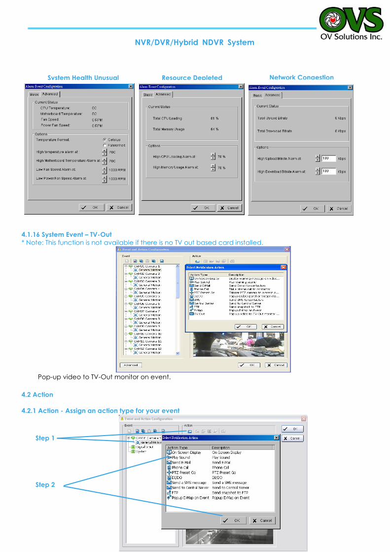
NVR/DVR/Hybrid NDVR System
- 66 -
4.1.16 System Event – TV-Out
* Note: This function is not available if there is no TV out based card installed.
Pop-up video to TV-Out monitor on event.
4.2 Action
4.2.1 Action - Assign an action type for your event
Step 1
Step 2
Resource Depleted System Health Unusual Network Congestion
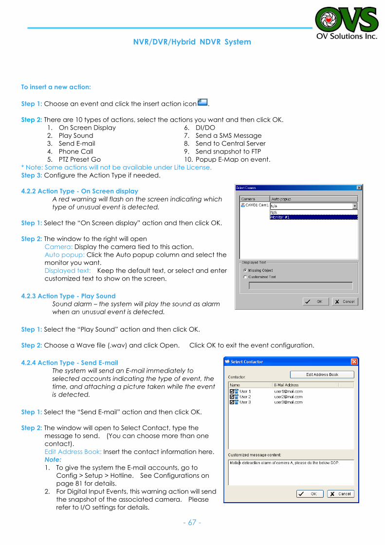
NVR/DVR/Hybrid NDVR System
- 67 -
To insert a new action:
Step 1: Choose an event and click the insert action icon .
Step 2: There are 10 types of actions, select the actions you want and then click OK.
1. On Screen Display
2. Play Sound
3. Send E-mail
4. Phone Call
5. PTZ Preset Go
6. DI/DO
7. Send a SMS Message
8. Send to Central Server
9. Send snapshot to FTP
10. Popup E-Map on event.
* Note: Some actions will not be available under Lite License.
Step 3: Configure the Action Type if needed.
4.2.2 Action Type - On Screen display
A red warning will flash on the screen indicating which
type of unusual event is detected.
Step 1: Select the “On Screen display” action and then click OK.
Step 2: The window to the right will open
Camera: Display the camera tied to this action.
Auto popup: Click the Auto popup column and select the
monitor you want.
Displayed text: Keep the default text, or select and enter
customized text to show on the screen.
4.2.3 Action Type - Play Sound
Sound alarm – the system will play the sound as alarm
when an unusual event is detected.
Step 1: Select the “Play Sound” action and then click OK.
Step 2: Choose a Wave file (.wav) and click Open. Click OK to exit the event configuration.
4.2.4 Action Type - Send E-mail
The system will send an E-mail immediately to
selected accounts indicating the type of event, the
time, and attaching a picture taken while the event
is detected.
Step 1: Select the “Send E-mail” action and then click OK.
Step 2: The window will open to Select Contact, type the
message to send. (You can choose more than one
contact).
Edit Address Book: Insert the contact information here.
Note:
1. To give the system the E-mail accounts, go to
Config > Setup > Hotline. See Configurations on
page 81 for details.
2. For Digital Input Events, this warning action will send
the snapshot of the associated camera. Please
refer to I/O settings for details.
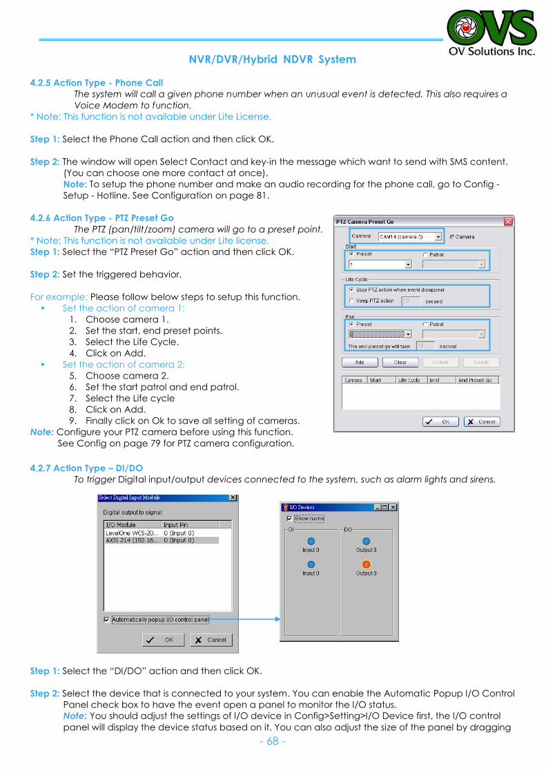
NVR/DVR/Hybrid NDVR System
- 68 -
4.2.5 Action Type - Phone Call
The system will call a given phone number when an unusual event is detected. This also requires a
Voice Modem to function.
* Note: This function is not available under Lite License.
Step 1: Select the Phone Call action and then click OK.
Step 2: The window will open Select Contact and key-in the message which want to send with SMS content.
(You can choose one more contact at once).
Note: To setup the phone number and make an audio recording for the phone call, go to Config -
Setup - Hotline. See Configuration on page 81.
4.2.6 Action Type - PTZ Preset Go
The PTZ (pan/tilt/zoom) camera will go to a preset point.
* Note: This function is not available under Lite license.
Step 1: Select the “PTZ Preset Go” action and then click OK.
Step 2: Set the triggered behavior.
For example: Please follow below steps to setup this function.
Set the action of camera 1:
1. Choose camera 1.
2. Set the start, end preset points.
3. Select the Life Cycle.
4. Click on Add.
Set the action of camera 2:
5. Choose camera 2.
6. Set the start patrol and end patrol.
7. Select the Life cycle
8. Click on Add.
9. Finally click on Ok to save all setting of cameras.
Note: Configure your PTZ camera before using this function.
See Config on page 79 for PTZ camera configuration.
4.2.7 Action Type – DI/DO
To trigger Digital input/output devices connected to the system, such as alarm lights and sirens.
Step 1: Select the “DI/DO” action and then click OK.
Step 2: Select the device that is connected to your system. You can enable the Automatic Popup I/O Control
Panel check box to have the event open a panel to monitor the I/O status.
Note: You should adjust the settings of I/O device in Config>Setting>I/O Device first, the I/O control
panel will display the device status based on it. You can also adjust the size of the panel by dragging
2.
3.
2.
1.
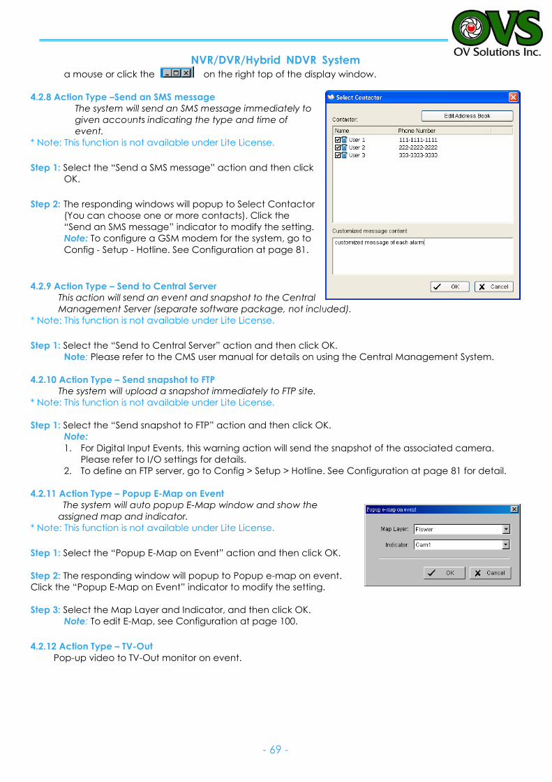
NVR/DVR/Hybrid NDVR System
- 69 -
a mouse or click the on the right top of the display window.
4.2.8 Action Type –Send an SMS message
The system will send an SMS message immediately to
given accounts indicating the type and time of
event.
* Note: This function is not available under Lite License.
Step 1: Select the “Send a SMS message” action and then click
OK.
Step 2: The responding windows will popup to Select Contactor
(You can choose one or more contacts). Click the
“Send an SMS message” indicator to modify the setting.
Note: To configure a GSM modem for the system, go to
Config - Setup - Hotline. See Configuration at page 81.
4.2.9 Action Type – Send to Central Server
This action will send an event and snapshot to the Central
Management Server (separate software package, not included).
* Note: This function is not available under Lite License.
Step 1: Select the “Send to Central Server” action and then click OK.
Note: Please refer to the CMS user manual for details on using the Central Management System.
4.2.10 Action Type – Send snapshot to FTP
The system will upload a snapshot immediately to FTP site.
* Note: This function is not available under Lite License.
Step 1: Select the “Send snapshot to FTP” action and then click OK.
Note:
1. For Digital Input Events, this warning action will send the snapshot of the associated camera.
Please refer to I/O settings for details.
2. To define an FTP server, go to Config > Setup > Hotline. See Configuration at page 81 for detail.
4.2.11 Action Type – Popup E-Map on Event
The system will auto popup E-Map window and show the
assigned map and indicator.
* Note: This function is not available under Lite License.
Step 1: Select the “Popup E-Map on Event” action and then click OK.
Step 2: The responding window will popup to Popup e-map on event.
Click the “Popup E-Map on Event” indicator to modify the setting.
Step 3: Select the Map Layer and Indicator, and then click OK.
Note: To edit E-Map, see Configuration at page 100.
4.2.12 Action Type – TV-Out
Pop-up video to TV-Out monitor on event.
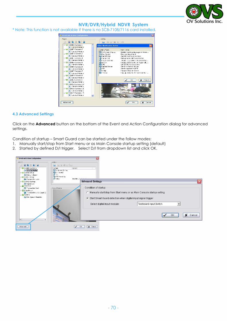
NVR/DVR/Hybrid NDVR System
- 70 -
* Note: This function is not available if there is no SCB-7108/7116 card installed.
4.3 Advanced Settings
Click on the Advanced button on the bottom of the Event and Action Configuration dialog for advanced
settings.
Condition of startup – Smart Guard can be started under the follow modes:
1. Manually start/stop from Start menu or as Main Console startup setting (default)
2. Started by defined D/I trigger. Select D/I from dropdown list and click OK.
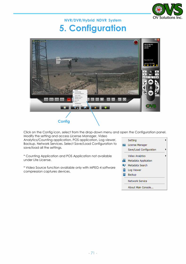
NVR/DVR/Hybrid NDVR System
- 71 -
5. Configuration
Click on the Config icon, select from the drop-down menu and open the Configuration panel.
Modify the setting and access License Manager, Video
Analytics/Counting application, POS application, Log viewer,
Backup, Network Services. Select Save/Load Configuration to
save/load all the settings.
* Counting Application and POS Application not available
under Lite License.
* Video Source function available only with MPEG-4 software
compression captures devices.
Config
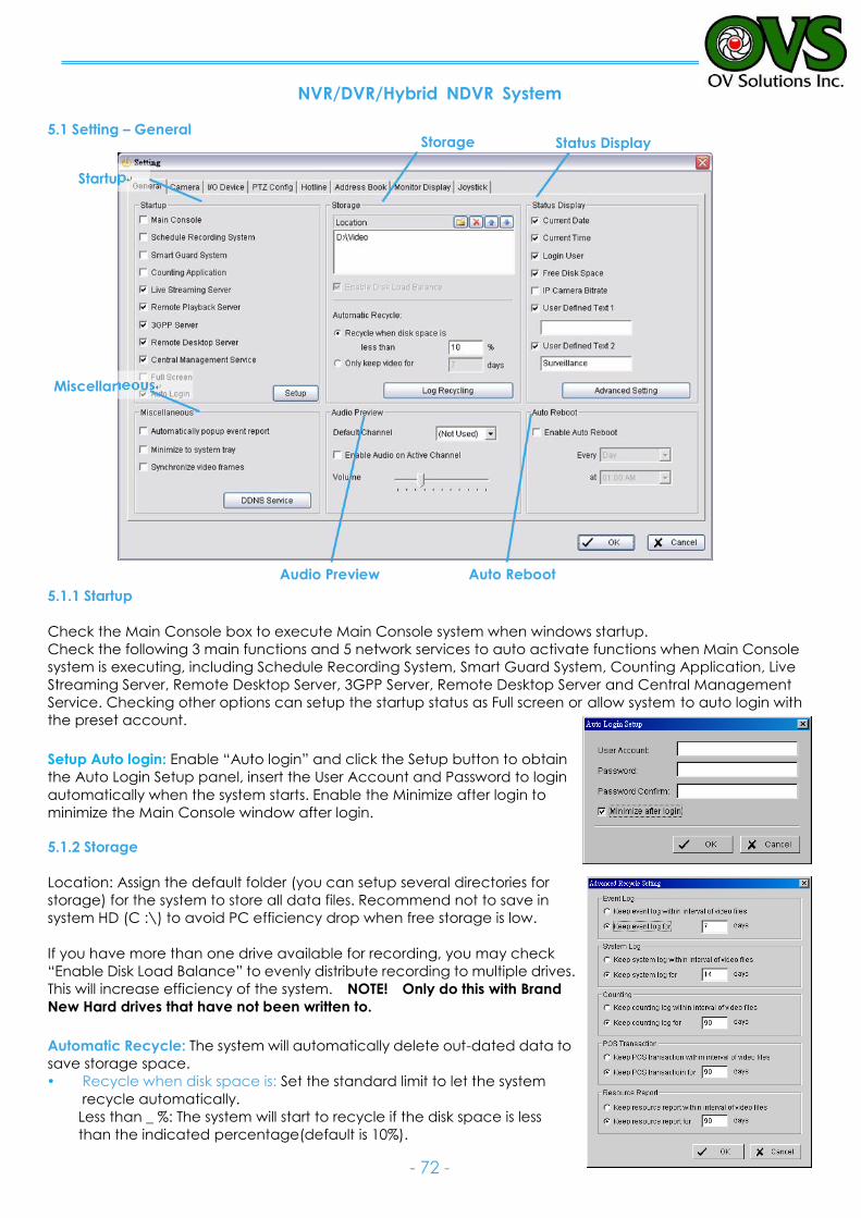
NVR/DVR/Hybrid NDVR System
- 72 -
5.1 Setting – General
5.1.1 Startup
Check the Main Console box to execute Main Console system when windows startup.
Check the following 3 main functions and 5 network services to auto activate functions when Main Console
system is executing, including Schedule Recording System, Smart Guard System, Counting Application, Live
Streaming Server, Remote Desktop Server, 3GPP Server, Remote Desktop Server and Central Management
Service. Checking other options can setup the startup status as Full screen or allow system to auto login with
the preset account.
Setup Auto login: Enable “Auto login” and click the Setup button to obtain
the Auto Login Setup panel, insert the User Account and Password to login
automatically when the system starts. Enable the Minimize after login to
minimize the Main Console window after login.
5.1.2 Storage
Location: Assign the default folder (you can setup several directories for
storage) for the system to store all data files. Recommend not to save in
system HD (C :\) to avoid PC efficiency drop when free storage is low.
If you have more than one drive available for recording, you may check
“Enable Disk Load Balance” to evenly distribute recording to multiple drives.
This will increase efficiency of the system. NOTE! Only do this with Brand
New Hard drives that have not been written to. Automatic Recycle: The system will automatically delete out-dated data to
save storage space.
Recycle when disk space is: Set the standard limit to let the system
recycle automatically.
Less than _ %: The system will start to recycle if the disk space is less
than the indicated percentage(default is 10%).
Miscellaneous
Status Display Storage
Startup
Auto Reboot Audio Preview
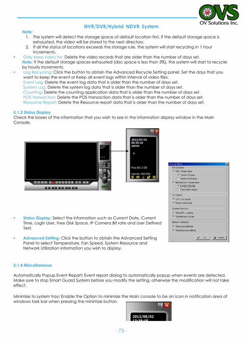
NVR/DVR/Hybrid NDVR System
- 73 -
Note:
1. The system will detect the storage space of default location first, if the default storage space is
exhausted, the video will be stored to the next directory.
2. If all the status of locations exceeds the storage rule, the system will start recycling in 1 hour
increments.
Only keep video for: Delete the video records that are older than the number of days set.
Note: If the default storage spaces exhausted (disc space is less than 3%), the system will start to recycle
by hourly increments.
Log Recycling: Click the button to obtain the Advanced Recycle Setting panel. Set the days that you
want to keep the event or Keep all event logs within interval of video files.
Event Log: Delete the event log data that is older than the number of days set.
System Log: Delete the system log data that is older than the number of days set.
Counting: Delete the counting application data that is older than the number of days set.
POS Transaction: Delete the POS transaction data that is older than the number of days set.
Resource Report: Delete the Resource report data that is older than the number of days set.
5.1.3 Status Display
Check the boxes of the information that you wish to see in the information display window in the Main
Console.
Status Display: Select the information such as Current Date, Current
Time, Login User, Free Disk Space, IP Camera Bit rate and User Defined
Text.
Advanced Setting: Click the button to obtain the Advanced Setting
Panel to select Temperature, Fan Speed, System Resource and
Network Utilization information you wish to display.
5.1.4 Miscellaneous
Automatically Popup Event Report: Event report dialog to automatically popup when events are detected.
Make sure to stop Smart Guard System before you modify the setting, otherwise the modification will not take
effect.
Minimize to system tray: Enable the Option to minimize the Main console to be an icon in notification area of
windows task bar when pressing the minimize button.
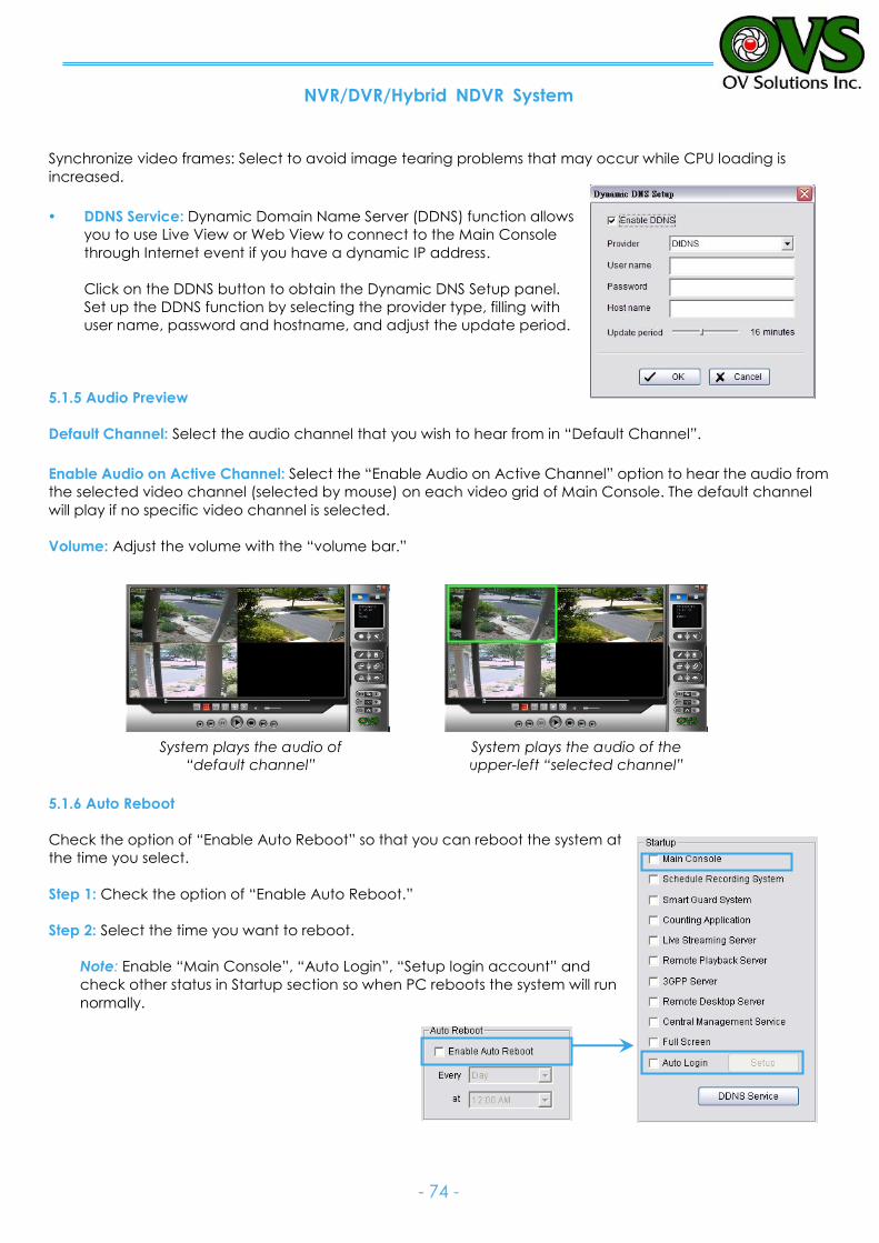
NVR/DVR/Hybrid NDVR System
- 74 -
Synchronize video frames: Select to avoid image tearing problems that may occur while CPU loading is
increased.
DDNS Service: Dynamic Domain Name Server (DDNS) function allows
you to use Live View or Web View to connect to the Main Console
through Internet event if you have a dynamic IP address.
Click on the DDNS button to obtain the Dynamic DNS Setup panel.
Set up the DDNS function by selecting the provider type, filling with
user name, password and hostname, and adjust the update period.
5.1.5 Audio Preview
Default Channel: Select the audio channel that you wish to hear from in “Default Channel”.
Enable Audio on Active Channel: Select the “Enable Audio on Active Channel” option to hear the audio from
the selected video channel (selected by mouse) on each video grid of Main Console. The default channel
will play if no specific video channel is selected.
Volume: Adjust the volume with the “volume bar.”
5.1.6 Auto Reboot
Check the option of “Enable Auto Reboot” so that you can reboot the system at
the time you select.
Step 1: Check the option of “Enable Auto Reboot.”
Step 2: Select the time you want to reboot.
Note: Enable “Main Console”, “Auto Login”, “Setup login account” and
check other status in Startup section so when PC reboots the system will run
normally.
System plays the audio of
“default channel”
System plays the audio of the
upper-left “selected channel”

NVR/DVR/Hybrid NDVR System
- 75 -
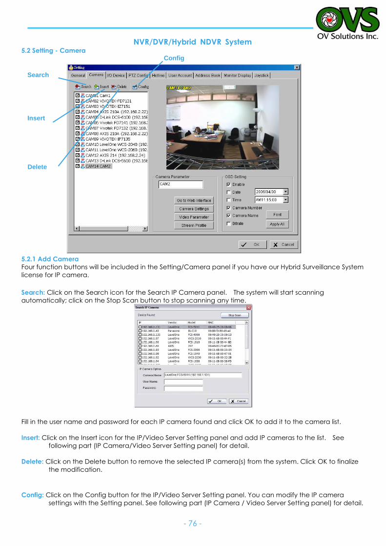
NVR/DVR/Hybrid NDVR System
- 76 -
5.2 Setting - Camera
5.2.1 Add Camera
Four function buttons will be included in the Setting/Camera panel if you have our Hybrid Surveillance System
license for IP camera.
Search: Click on the Search icon for the Search IP Camera panel. The system will start scanning
automatically; click on the Stop Scan button to stop scanning any time.
Fill in the user name and password for each IP camera found and click OK to add it to the camera list.
Insert: Click on the Insert icon for the IP/Video Server Setting panel and add IP cameras to the list. See
following part (IP Camera/Video Server Setting panel) for detail.
Delete: Click on the Delete button to remove the selected IP camera(s) from the system. Click OK to finalize
the modification.
Config: Click on the Config button for the IP/Video Server Setting panel. You can modify the IP camera
settings with the Setting panel. See following part (IP Camera / Video Server Setting panel) for detail.
Config
Delete
Insert
Search
Config
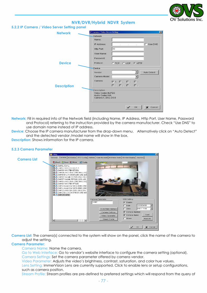
NVR/DVR/Hybrid NDVR System
- 77 -
5.2.2 IP Camera / Video Server Setting panel
Network: Fill in required info of the Network field (including Name, IP Address, Http Port, User Name, Password
and Protocol) referring to the instruction provided by the camera manufacturer. Check “Use DNS” to
use domain name instead of IP address.
Device: Choose the IP camera manufacturer from the drop-down menu. Alternatively click on “Auto Detect”
and the detected vendor /model name will show in the box.
Description: Shows information for the IP camera.
5.2.3 Camera Parameter
Camera List: The camera(s) connected to the system will show on the panel, click the name of the camera to
adjust the setting.
Camera Parameter:
Camera Name: Name the camera.
Go to Web Interface: Go to vendor’s website interface to configure the camera setting (optional).
Camera Settings: Set the camera parameter offered by camera vendor.
Video Parameter: Adjusts the video’s brightness, contrast, saturation, and color hue values.
Lens Setting: ImmerVision Lens are currently supported. Click to enable lens or setup configurations,
such as camera position.
Stream Profile: Stream profiles are pre-defined to preferred settings which will respond from the query of
Camera List
Device
Network
Description
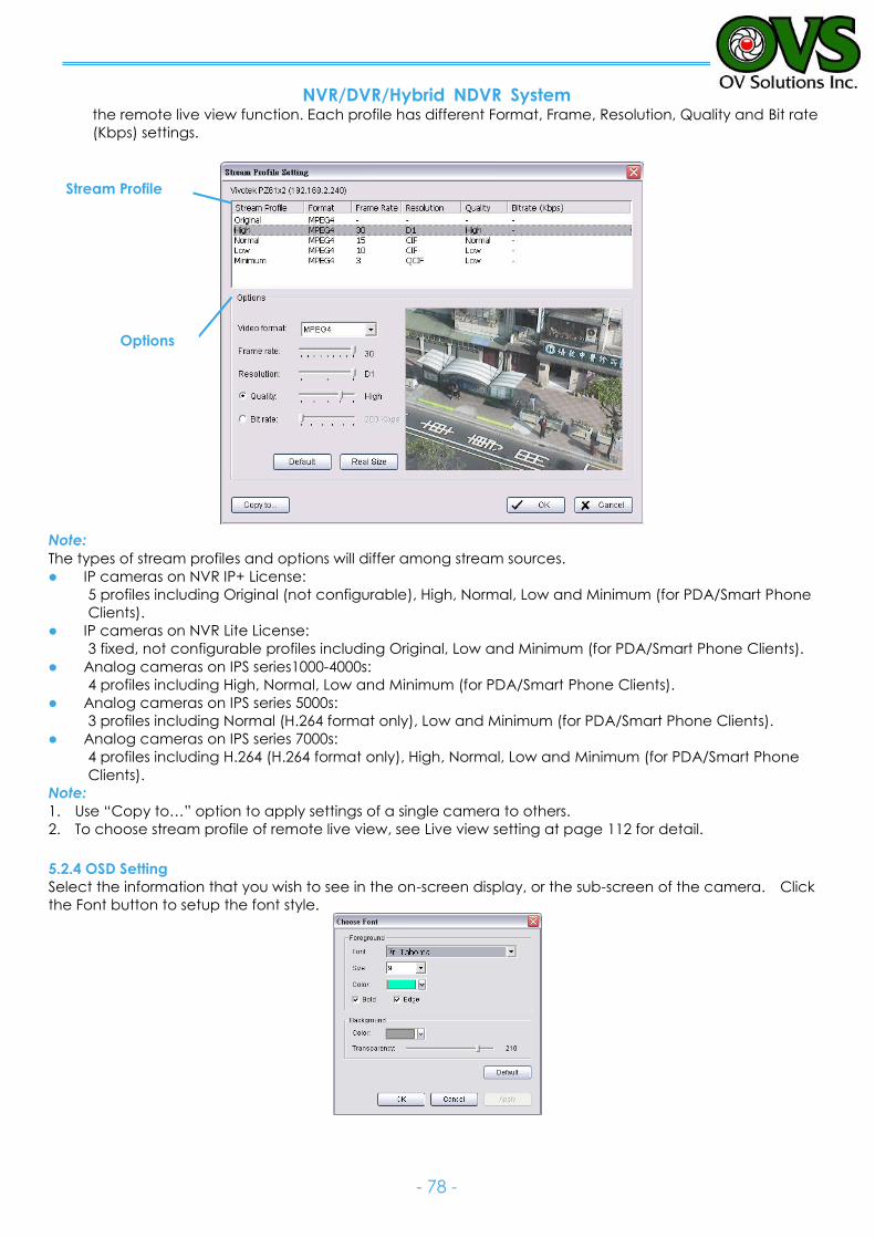
NVR/DVR/Hybrid NDVR System
- 78 -
the remote live view function. Each profile has different Format, Frame, Resolution, Quality and Bit rate
(Kbps) settings.
Note:
The types of stream profiles and options will differ among stream sources.
IP cameras on NVR IP+ License:
5 profiles including Original (not configurable), High, Normal, Low and Minimum (for PDA/Smart Phone
Clients).
IP cameras on NVR Lite License:
3 fixed, not configurable profiles including Original, Low and Minimum (for PDA/Smart Phone Clients).
Analog cameras on IPS series1000-4000s:
4 profiles including High, Normal, Low and Minimum (for PDA/Smart Phone Clients).
Analog cameras on IPS series 5000s:
3 profiles including Normal (H.264 format only), Low and Minimum (for PDA/Smart Phone Clients).
Analog cameras on IPS series 7000s:
4 profiles including H.264 (H.264 format only), High, Normal, Low and Minimum (for PDA/Smart Phone
Clients).
Note:
1. Use “Copy to…” option to apply settings of a single camera to others.
2. To choose stream profile of remote live view, see Live view setting at page 112 for detail.
5.2.4 OSD Setting
Select the information that you wish to see in the on-screen display, or the sub-screen of the camera. Click
the Font button to setup the font style.
Stream Profile
Options
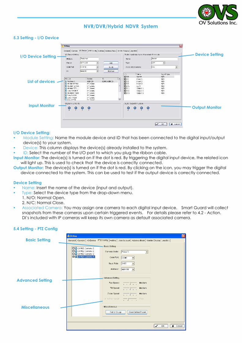
NVR/DVR/Hybrid NDVR System
- 79 -
Advanced Setting
5.3 Setting - I/O Device
I/O Device Setting:
Module Setting: Name the module device and ID that has been connected to the digital input/output
device(s) to your system.
Device: This column displays the device(s) already installed to the system.
ID: Select the number of the I/O port to which you plug the ribbon cable.
Input Monitor: The device(s) is turned on if the dot is red. By triggering the digital input device, the related icon
will light up. This is used to check that the device is correctly connected. Output Monitor: The device(s) is turned on if the dot is red. By clicking on the icon, you may trigger the digital
device connected to the system. This can be used to test if the output device is correctly connected.
Device Setting
Name: Insert the name of the device (input and output).
Type: Select the device type from the drop-down menu.
1. N/O: Normal Open.
2. N/C: Normal Close.
Associated Camera: You may assign one camera to each digital input device. Smart Guard will collect
snapshots from these cameras upon certain triggered events. For details please refer to 4.2 - Action.
DI’s included with IP cameras will keep its own camera as default associated camera.
5.4 Setting - PTZ Config
Basic Setting
Miscellaneous
Output Monitor Input Monitor
List of devices
Device Setting I/O Device Setting
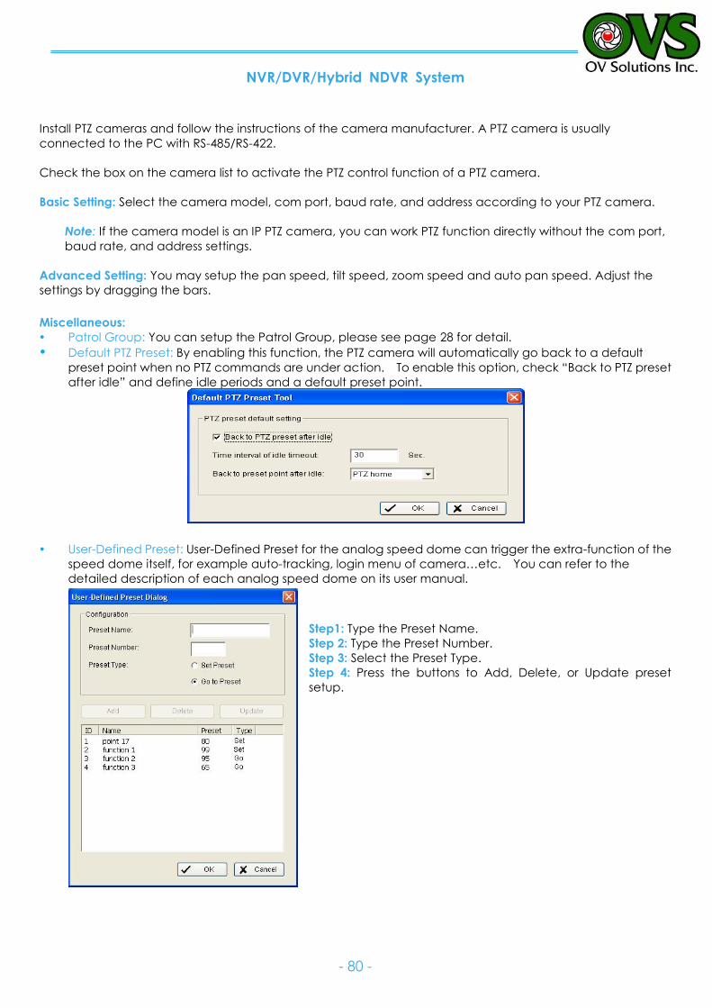
NVR/DVR/Hybrid NDVR System
- 80 -
Install PTZ cameras and follow the instructions of the camera manufacturer. A PTZ camera is usually
connected to the PC with RS-485/RS-422.
Check the box on the camera list to activate the PTZ control function of a PTZ camera.
Basic Setting: Select the camera model, com port, baud rate, and address according to your PTZ camera.
Note: If the camera model is an IP PTZ camera, you can work PTZ function directly without the com port,
baud rate, and address settings.
Advanced Setting: You may setup the pan speed, tilt speed, zoom speed and auto pan speed. Adjust the
settings by dragging the bars.
Miscellaneous:
Patrol Group: You can setup the Patrol Group, please see page 28 for detail.
Default PTZ Preset: By enabling this function, the PTZ camera will automatically go back to a default
preset point when no PTZ commands are under action. To enable this option, check “Back to PTZ preset
after idle” and define idle periods and a default preset point.
User-Defined Preset: User-Defined Preset for the analog speed dome can trigger the extra-function of the
speed dome itself, for example auto-tracking, login menu of camera…etc. You can refer to the
detailed description of each analog speed dome on its user manual.
Step1: Type the Preset Name.
Step 2: Type the Preset Number.
Step 3: Select the Preset Type.
Step 4: Press the buttons to Add, Delete, or Update preset
setup.
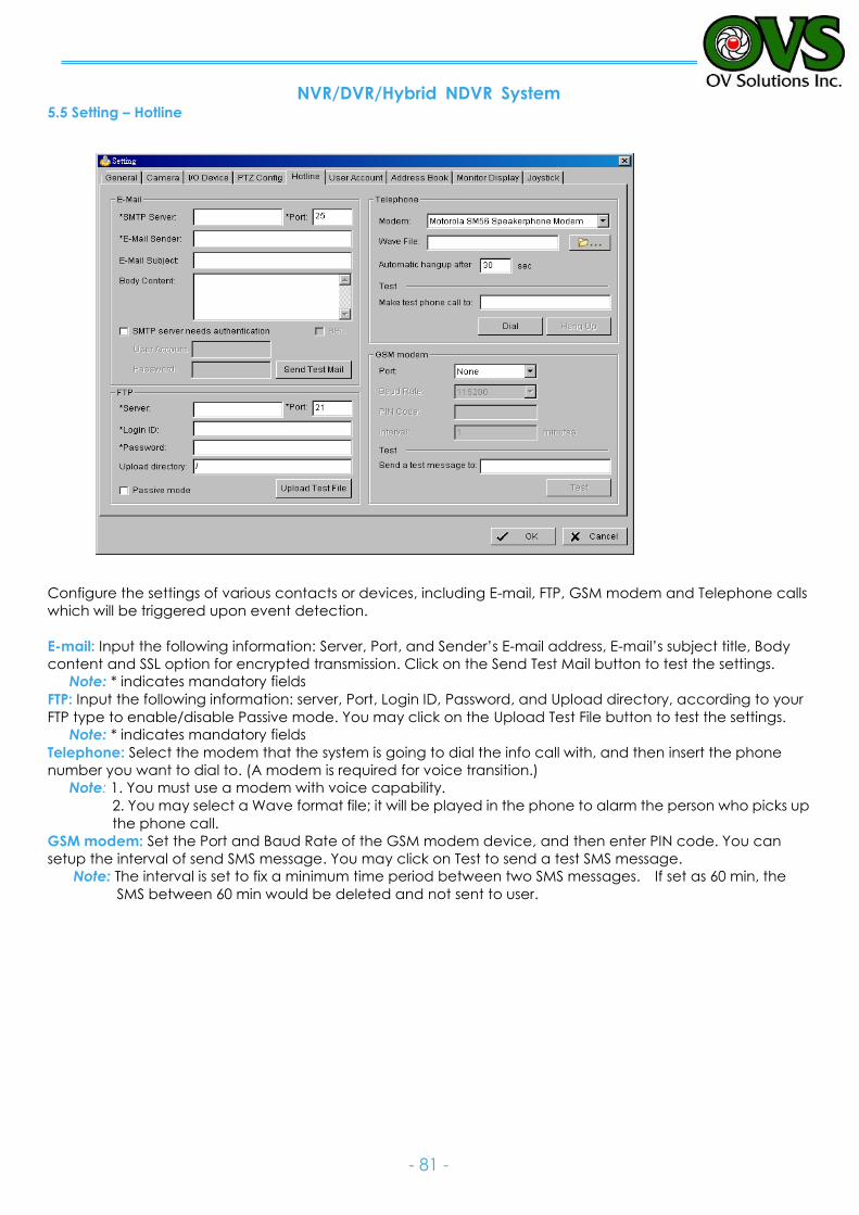
NVR/DVR/Hybrid NDVR System
- 81 -
5.5 Setting – Hotline
Configure the settings of various contacts or devices, including E-mail, FTP, GSM modem and Telephone calls
which will be triggered upon event detection.
E-mail: Input the following information: Server, Port, and Sender’s E-mail address, E-mail’s subject title, Body
content and SSL option for encrypted transmission. Click on the Send Test Mail button to test the settings.
Note: * indicates mandatory fields
FTP: Input the following information: server, Port, Login ID, Password, and Upload directory, according to your
FTP type to enable/disable Passive mode. You may click on the Upload Test File button to test the settings.
Note: * indicates mandatory fields
Telephone: Select the modem that the system is going to dial the info call with, and then insert the phone
number you want to dial to. (A modem is required for voice transition.)
Note: 1. You must use a modem with voice capability.
2. You may select a Wave format file; it will be played in the phone to alarm the person who picks up
the phone call.
GSM modem: Set the Port and Baud Rate of the GSM modem device, and then enter PIN code. You can
setup the interval of send SMS message. You may click on Test to send a test SMS message.
Note: The interval is set to fix a minimum time period between two SMS messages. If set as 60 min, the
SMS between 60 min would be deleted and not sent to user.
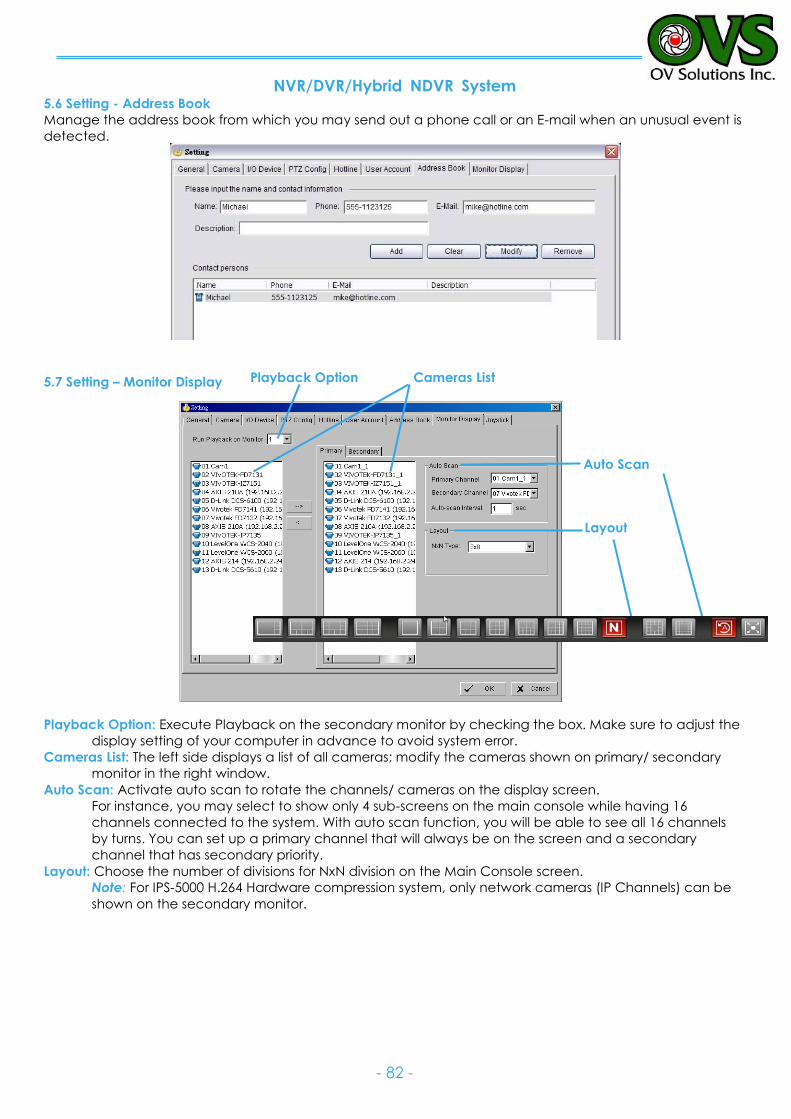
NVR/DVR/Hybrid NDVR System
- 82 -
5.6 Setting - Address Book
Manage the address book from which you may send out a phone call or an E-mail when an unusual event is
detected.
5.7 Setting – Monitor Display
Playback Option: Execute Playback on the secondary monitor by checking the box. Make sure to adjust the
display setting of your computer in advance to avoid system error.
Cameras List: The left side displays a list of all cameras; modify the cameras shown on primary/ secondary
monitor in the right window.
Auto Scan: Activate auto scan to rotate the channels/ cameras on the display screen.
For instance, you may select to show only 4 sub-screens on the main console while having 16
channels connected to the system. With auto scan function, you will be able to see all 16 channels
by turns. You can set up a primary channel that will always be on the screen and a secondary
channel that has secondary priority.
Layout: Choose the number of divisions for NxN division on the Main Console screen.
Note: For IPS-5000 H.264 Hardware compression system, only network cameras (IP Channels) can be
shown on the secondary monitor.
Layout
Auto Scan
Cameras List Playback Option
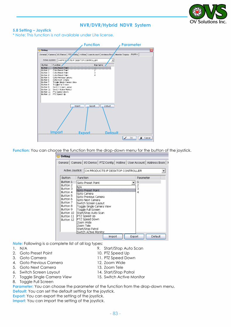
NVR/DVR/Hybrid NDVR System
- 83 -
5.8 Setting – Joystick
* Note: This function is not available under Lite license.
Function: You can choose the function from the drop-down menu for the button of the joystick.
Note: Following is a complete list of all log types:
1. N/A
2. Goto Preset Point
3. Goto Camera
4. Goto Previous Camera
5. Goto Next Camera
6. Switch Screen Layout
7. Toggle Single Camera View
8. Toggle Full Screen
9. Start/Stop Auto Scan
10. PTZ Speed Up
11. PTZ Speed Down
12. Zoom Wide
13. Zoom Tele
14. Start/Stop Patrol
15. Switch Active Monitor
Parameter: You can choose the parameter of the function from the drop-down menu.
Default: You can set the default setting for the joystick.
Export: You can export the setting of the joystick.
Import: You can import the setting of the joystick.
Parameter Function
Default Export Import
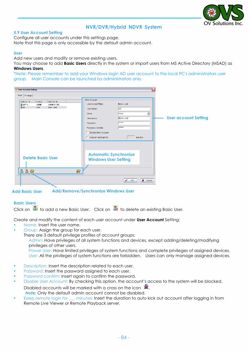
NVR/DVR/Hybrid NDVR System
- 84 -
5.9 User Account Setting
Configure all user accounts under this settings page.
Note that this page is only accessible by the default admin account.
User
Add new users and modify or remove existing users.
You may choose to add Basic Users directly in the system or import users from MS Active Directory (MSAD) as
Windows Users.
*Note: Please remember to add your Windows login AD user account to the local PC's administrators user
group. Main Console can be launched by administrators only.
Basic Users
Click on to add a new Basic User. Click on to delete an existing Basic User.
Create and modify the content of each user account under User Account Setting:
Name: Insert the user name.
Group: Assign the group for each user.
There are 3 default privilege profiles of account groups:
Admin: Have privileges of all system functions and devices, except adding/deleting/modifying
privileges of other users.
Power User: Have limited privileges of system functions and complete privileges of assigned devices.
User: All the privileges of system functions are forbidden. Users can only manage assigned devices.
Description: Insert the description related to each user.
Password: Insert the password assigned to each user.
Password confirm: Insert again to confirm the password.
Disable User Account: By checking this option, the account’s access to the system will be blocked.
Disabled accounts will be marked with a cross on the icon .
Note: Only the default admin account cannot be disabled.
Keep remote login for ___ minutes: Insert the duration to auto kick out account after logging in from
Remote Live Viewer or Remote Playback server.
User account Setting
Add Basic User
Delete Basic User
Add/Remove/Synchronize Windows User
Automatic Synchronize
Windows User Setting
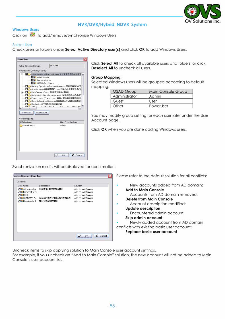
NVR/DVR/Hybrid NDVR System
- 85 -
Windows Users
Click on to add/remove/synchronize Windows Users.
Select User
Check users or folders under Select Active Directory user(s) and click OK to add Windows Users.
Click Select All to check all available users and folders, or click
Deselect All to uncheck all users.
Group Mapping:
Selected Windows users will be grouped according to default
mapping:
MSAD Group Main Console Group
Administrator Admin
Guest User
Other PowerUser
You may modify group setting for each user later under the User
Account page.
Click OK when you are done adding Windows users.
Synchronization results will be displayed for confirmation.
Please refer to the default solution for all conflicts:
New accounts added from AD domain:
Add to Main Console
Accounts from AD domain removed:
Delete from Main Console
Account description modified:
Update description
Encountered admin account:
Skip admin account
Newly added account from AD domain
conflicts with existing basic user account:
Replace basic user account
Uncheck items to skip applying solution to Main Console user account settings.
For example, if you uncheck an “Add to Main Console” solution, the new account will not be added to Main
Console’s user account list.
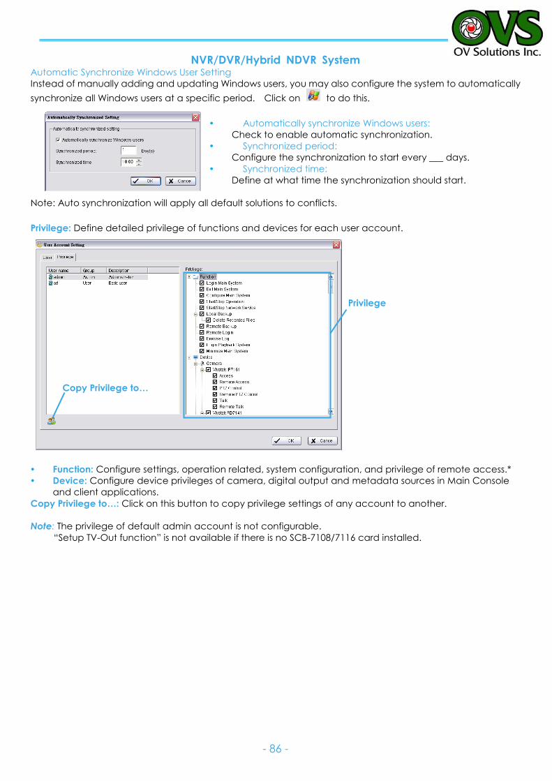
NVR/DVR/Hybrid NDVR System
- 86 -
Automatic Synchronize Windows User Setting
Instead of manually adding and updating Windows users, you may also configure the system to automatically
synchronize all Windows users at a specific period. Click on to do this.
Automatically synchronize Windows users:
Check to enable automatic synchronization.
Synchronized period:
Configure the synchronization to start every ___ days.
Synchronized time:
Define at what time the synchronization should start.
Note: Auto synchronization will apply all default solutions to conflicts.
Privilege: Define detailed privilege of functions and devices for each user account.
Function: Configure settings, operation related, system configuration, and privilege of remote access.*
Device: Configure device privileges of camera, digital output and metadata sources in Main Console
and client applications.
Copy Privilege to…: Click on this button to copy privilege settings of any account to another.
Note: The privilege of default admin account is not configurable.
“Setup TV-Out function” is not available if there is no SCB-7108/7116 card installed.
Privilege
Copy Privilege to…
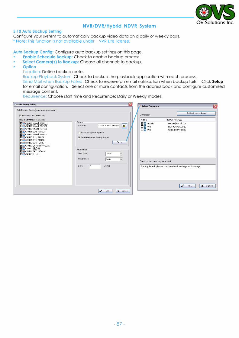
NVR/DVR/Hybrid NDVR System
- 87 -
5.10 Auto Backup Setting
Configure your system to automatically backup video data on a daily or weekly basis.
* Note: This function is not available under NVR Lite license.
Auto Backup Config: Configure auto backup settings on this page.
Enable Schedule Backup: Check to enable backup process.
Select Camera(s) to Backup: Choose all channels to backup.
Option
Location: Define backup route.
Backup Playback System: Check to backup the playback application with each process.
Send Mail when Backup Failed: Check to receive an email notification when backup fails. Click Setup
for email configuration. Select one or more contacts from the address book and configure customized
message content.
Recurrence: Choose start time and Recurrence: Daily or Weekly modes.
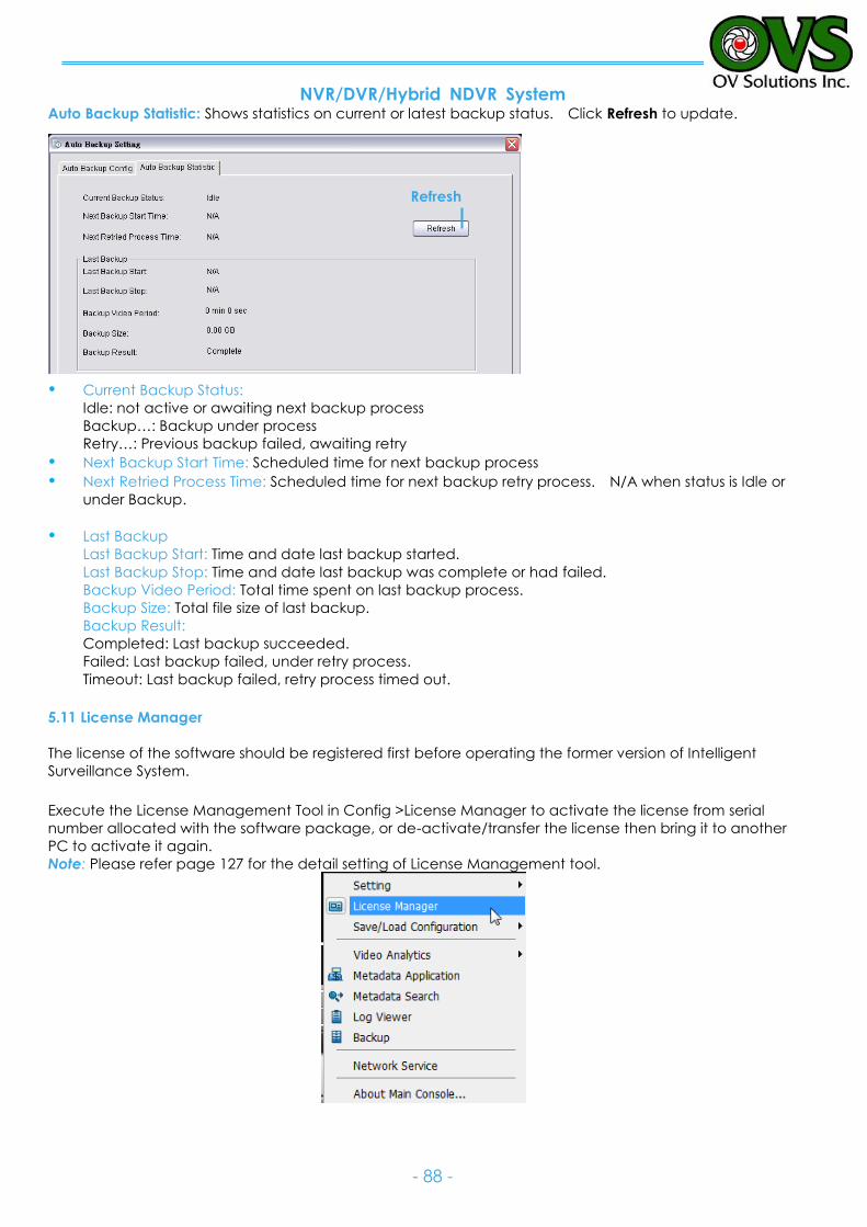
NVR/DVR/Hybrid NDVR System
- 88 -
Auto Backup Statistic: Shows statistics on current or latest backup status. Click Refresh to update.
Current Backup Status:
Idle: not active or awaiting next backup process
Backup…: Backup under process
Retry…: Previous backup failed, awaiting retry Next Backup Start Time: Scheduled time for next backup process Next Retried Process Time: Scheduled time for next backup retry process. N/A when status is Idle or
under Backup.
Last Backup Last Backup Start: Time and date last backup started.
Last Backup Stop: Time and date last backup was complete or had failed.
Backup Video Period: Total time spent on last backup process.
Backup Size: Total file size of last backup.
Backup Result:
Completed: Last backup succeeded.
Failed: Last backup failed, under retry process.
Timeout: Last backup failed, retry process timed out.
5.11 License Manager
The license of the software should be registered first before operating the former version of Intelligent
Surveillance System.
Execute the License Management Tool in Config >License Manager to activate the license from serial
number allocated with the software package, or de-activate/transfer the license then bring it to another
PC to activate it again.
Note: Please refer page 127 for the detail setting of License Management tool.
Refresh
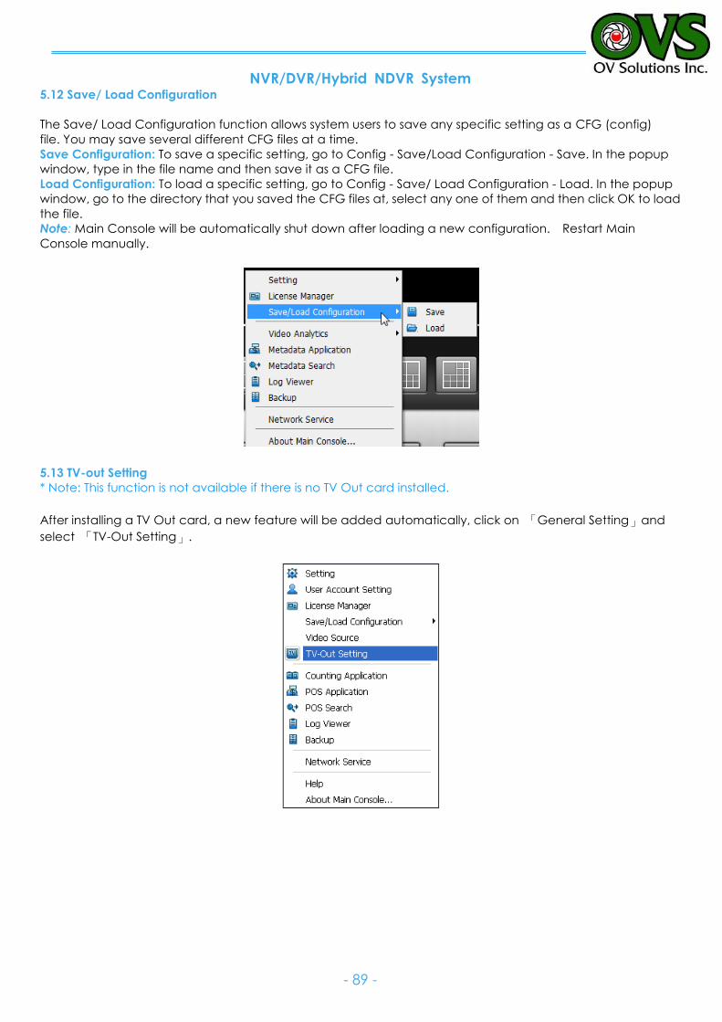
NVR/DVR/Hybrid NDVR System
- 89 -
5.12 Save/ Load Configuration
The Save/ Load Configuration function allows system users to save any specific setting as a CFG (config)
file. You may save several different CFG files at a time.
Save Configuration: To save a specific setting, go to Config - Save/Load Configuration - Save. In the popup
window, type in the file name and then save it as a CFG file.
Load Configuration: To load a specific setting, go to Config - Save/ Load Configuration - Load. In the popup
window, go to the directory that you saved the CFG files at, select any one of them and then click OK to load
the file.
Note: Main Console will be automatically shut down after loading a new configuration. Restart Main
Console manually.
5.13 TV-out Setting
* Note: This function is not available if there is no TV Out card installed.
After installing a TV Out card, a new feature will be added automatically, click on 「General Setting」and
select 「TV-Out Setting」.
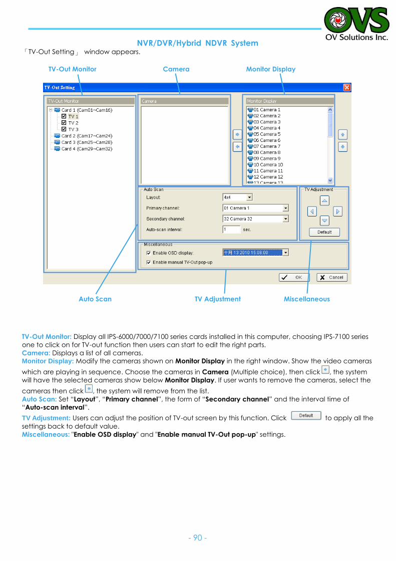
NVR/DVR/Hybrid NDVR System
- 90 -
「TV-Out Setting」 window appears.
TV-Out Monitor Camera Monitor Display
Auto Scan TV Adjustment Miscellaneous
TV-Out Monitor: Display all IPS-6000/7000/7100 series cards installed in this computer, choosing IPS-7100 series
one to click on for TV-out function then users can start to edit the right parts.
Camera: Displays a list of all cameras.
Monitor Display: Modify the cameras shown on Monitor Display in the right window. Show the video cameras
which are playing in sequence. Choose the cameras in Camera (Multiple choice), then click , the system
will have the selected cameras show below Monitor Display. If user wants to remove the cameras, select the
cameras then click , the system will remove from the list.
Auto Scan: Set “Layout”, “Primary channel”, the form of “Secondary channel” and the interval time of
“Auto-scan interval”.
TV Adjustment: Users can adjust the position of TV-out screen by this function. Click to apply all the
settings back to default value.
Miscellaneous: "Enable OSD display" and "Enable manual TV-Out pop-up" settings.
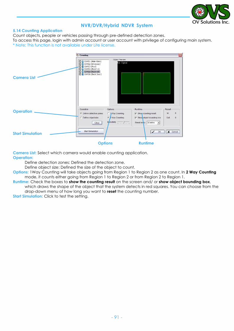
NVR/DVR/Hybrid NDVR System
- 91 -
5.14 Counting Application
Count objects, people or vehicles passing through pre-defined detection zones.
To access this page, login with admin account or user account with privilege of configuring main system. * Note: This function is not available under Lite license.
Camera List
Operation
Start Simulation
Options Runtime
Camera List: Select which camera would enable counting application.
Operation:
Define detection zones: Defined the detection zone.
Define object size: Defined the size of the object to count.
Options: 1Way Counting will take objects going from Region 1 to Region 2 as one count. In 2 Way Counting
mode, it counts either going from Region 1 to Region 2 or from Region 2 to Region 1.
Runtime: Check the boxes to show the counting result on the screen and/ or show object bounding box,
which draws the shape of the object that the system detects in red squares. You can choose from the
drop-down menu of how long you want to reset the counting number.
Start Simulation: Click to test the setting.
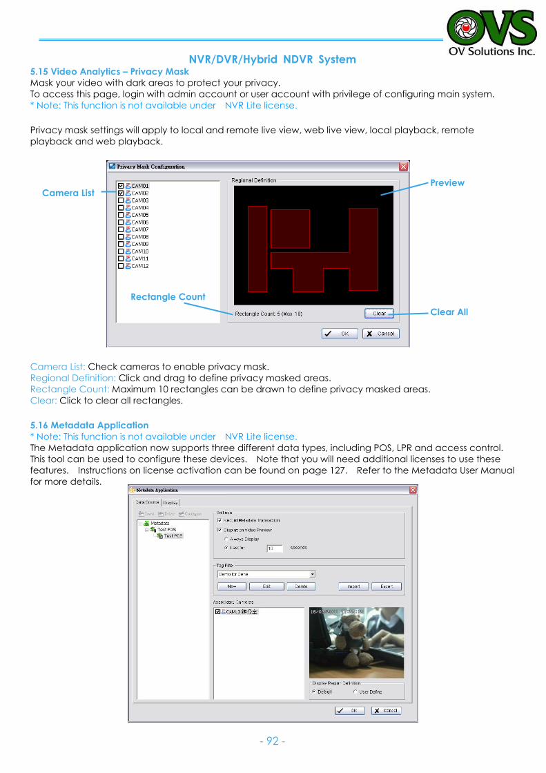
NVR/DVR/Hybrid NDVR System
- 92 -
5.15 Video Analytics – Privacy Mask
Mask your video with dark areas to protect your privacy.
To access this page, login with admin account or user account with privilege of configuring main system.
* Note: This function is not available under NVR Lite license.
Privacy mask settings will apply to local and remote live view, web live view, local playback, remote
playback and web playback.
Camera List: Check cameras to enable privacy mask.
Regional Definition: Click and drag to define privacy masked areas.
Rectangle Count: Maximum 10 rectangles can be drawn to define privacy masked areas.
Clear: Click to clear all rectangles. 5.16 Metadata Application
* Note: This function is not available under NVR Lite license.
The Metadata application now supports three different data types, including POS, LPR and access control.
This tool can be used to configure these devices. Note that you will need additional licenses to use these
features. Instructions on license activation can be found on page 127. Refer to the Metadata User Manual
for more details.
Camera List
Rectangle Count
Clear All
Preview
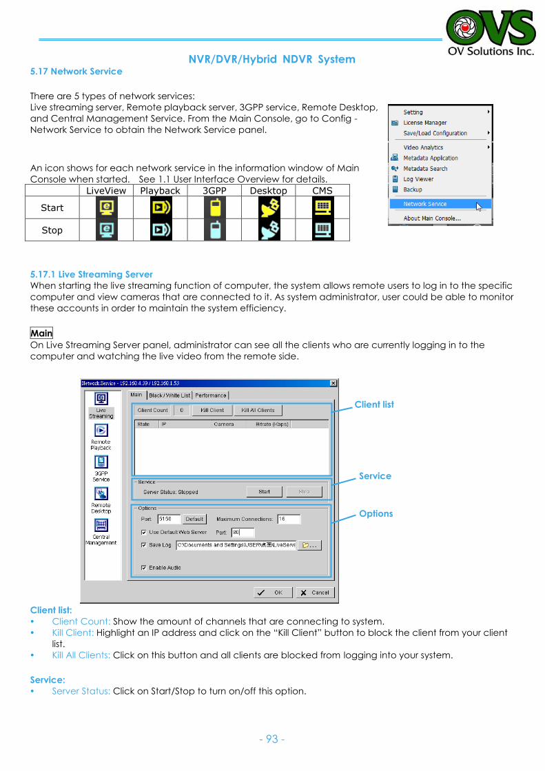
NVR/DVR/Hybrid NDVR System
- 93 -
5.17 Network Service
There are 5 types of network services:
Live streaming server, Remote playback server, 3GPP service, Remote Desktop,
and Central Management Service. From the Main Console, go to Config -
Network Service to obtain the Network Service panel.
An icon shows for each network service in the information window of Main
Console when started. See 1.1 User Interface Overview for details.
LiveView Playback 3GPP Desktop CMS
Start
Stop
5.17.1 Live Streaming Server
When starting the live streaming function of computer, the system allows remote users to log in to the specific
computer and view cameras that are connected to it. As system administrator, user could be able to monitor
these accounts in order to maintain the system efficiency.
Main
On Live Streaming Server panel, administrator can see all the clients who are currently logging in to the
computer and watching the live video from the remote side.
Client list:
Client Count: Show the amount of channels that are connecting to system.
Kill Client: Highlight an IP address and click on the “Kill Client” button to block the client from your client
list.
Kill All Clients: Click on this button and all clients are blocked from logging into your system.
Service:
Server Status: Click on Start/Stop to turn on/off this option.
Client list
Service
Options
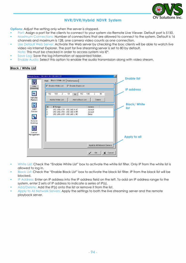
NVR/DVR/Hybrid NDVR System
- 94 -
Options: Adjust the setting only when the server is stopped.
Port: Assign a port for the clients to connect to your system via Remote Live Viewer. Default port is 5150.
Maximum Connections: Number of connections that are allowed to connect to the system. Default is 16
channels and maximum is 128, one camera video counts as one connection.
Use Default Web Server: Activate the Web server by checking the box; clients will be able to watch live
video via Internet Explorer. The port for live streaming server is set to 80 by default.
Note: This must be checked in order to access system via IE*.
Save Log: Save the log information at appointed folder.
Enable Audio: Select this option to enable the audio transmission along with video stream.
Black / White List
White List: Check the “Enable White List” box to activate the white list filter. Only IP from the white list is
allowed to log in.
Black List: Check the “Enable Black List” box to activate the black list filter. IP from the black list will be
blocked.
IP Address: Enter an IP address into the IP address field on the left. To add an IP address range to the
system, enter 2 sets of IP address to indicate a series of IP(s).
Add/Delete: Add the IP(s) onto the list or remove it from the list.
Apply to All Network Servers: Apply the settings to both the live streaming server and the remote
playback server.
Black/ White
list
IP address
Enable list
Apply to all
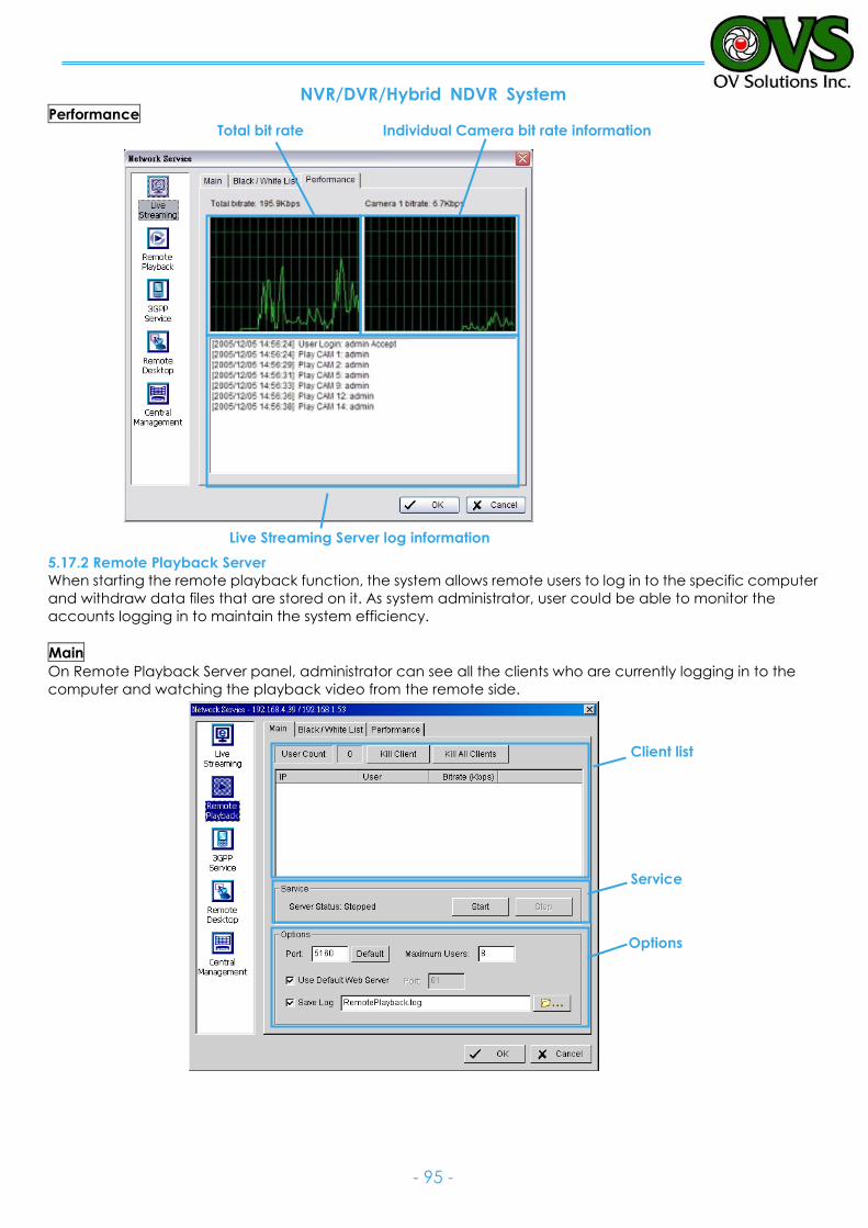
NVR/DVR/Hybrid NDVR System
- 95 -
Performance
5.17.2 Remote Playback Server
When starting the remote playback function, the system allows remote users to log in to the specific computer
and withdraw data files that are stored on it. As system administrator, user could be able to monitor the
accounts logging in to maintain the system efficiency.
Main
On Remote Playback Server panel, administrator can see all the clients who are currently logging in to the
computer and watching the playback video from the remote side.
Options
Service
Client list
Live Streaming Server log information
Individual Camera bit rate information
Total bit rate
NVR/DVR/Hybrid NDVR System
- 96 -
Client list:
User Count: Show the number of users that are connecting to system.
Kill Client: Highlight an IP address and click on the “Kill Client” button to block the client from your client
list.
Kill All Clients: Click on this button and then block all the clients logging to your system.
Service:
Server Status: Click on Start/Stop to turn on/off this option.
Options: Adjust the setting only when the server is stopped.
Port: Assign a port for the clients to connect to your system via Remote playback server. Default port is
5160.
Maximum Users: Number of connections that are allowed to connect to the system. Default is 8 users and
maximum is 64.
Note: One user counts as one account that is logging in to the server.
Use Default Web Server: Activate the Web server by checking the box; clients will be able to watch live
video via Internet Explorer. The port for live streaming server is set to 80 by default.
Note: Must check this item for system access via IE*.
Save Log: Save the log information at appointed folder.
Black / White List and Performance - Please refer to Live Streaming Server section
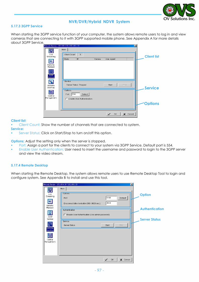
NVR/DVR/Hybrid NDVR System
- 97 -
5.17.3 3GPP Service
When starting the 3GPP service function of your computer, the system allows remote users to log in and view
cameras that are connecting to it with 3GPP supported mobile phone. See Appendix A for more details
about 3GPP Service.
Client list:
Client Count: Show the number of channels that are connected to system.
Service:
Server Status: Click on Start/Stop to turn on/off this option.
Options: Adjust the setting only when the server is stopped.
Port: Assign a port for the clients to connect to your system via 3GPP Service. Default port is 554.
Enable User Authentication: User need to insert the username and password to login to the 3GPP server
and view the video stream.
5.17.4 Remote Desktop
When starting the Remote Desktop, the system allows remote users to use Remote Desktop Tool to login and
configure system. See Appendix B to install and use this tool.
Options
Service
Client list
Option
Authentication
Server Status
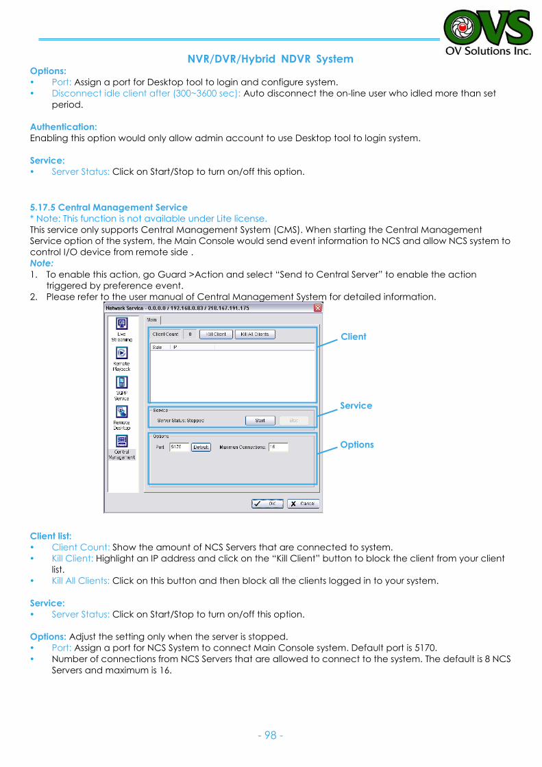
NVR/DVR/Hybrid NDVR System
- 98 -
Options:
Port: Assign a port for Desktop tool to login and configure system.
Disconnect idle client after (300~3600 sec): Auto disconnect the on-line user who idled more than set
period.
Authentication:
Enabling this option would only allow admin account to use Desktop tool to login system.
Service:
Server Status: Click on Start/Stop to turn on/off this option.
5.17.5 Central Management Service
* Note: This function is not available under Lite license. This service only supports Central Management System (CMS). When starting the Central Management
Service option of the system, the Main Console would send event information to NCS and allow NCS system to
control I/O device from remote side .
Note:
1. To enable this action, go Guard >Action and select “Send to Central Server” to enable the action
triggered by preference event.
2. Please refer to the user manual of Central Management System for detailed information.
Client list:
Client Count: Show the amount of NCS Servers that are connected to system.
Kill Client: Highlight an IP address and click on the “Kill Client” button to block the client from your client
list.
Kill All Clients: Click on this button and then block all the clients logged in to your system.
Service:
Server Status: Click on Start/Stop to turn on/off this option.
Options: Adjust the setting only when the server is stopped.
Port: Assign a port for NCS System to connect Main Console system. Default port is 5170.
Number of connections from NCS Servers that are allowed to connect to the system. The default is 8 NCS
Servers and maximum is 16.
Client
Service
Options
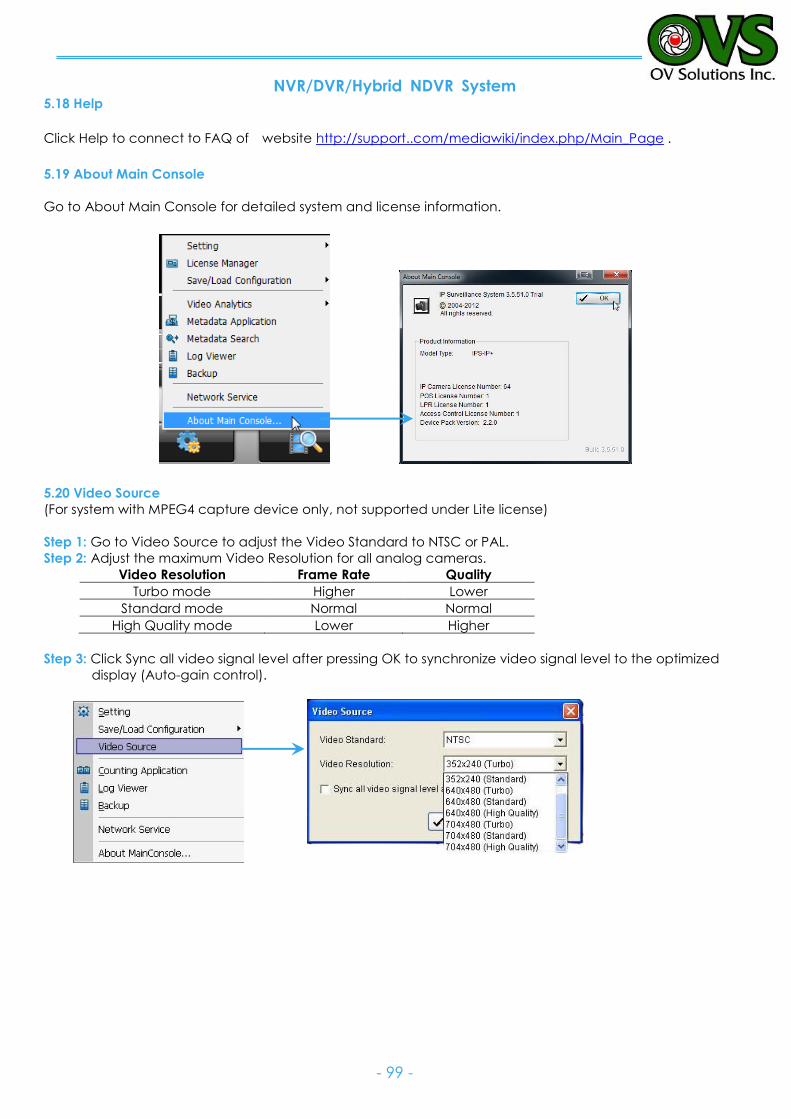
NVR/DVR/Hybrid NDVR System
- 99 -
5.18 Help
Click Help to connect to FAQ of website http://support..com/mediawiki/index.php/Main_Page .
5.19 About Main Console
Go to About Main Console for detailed system and license information.
5.20 Video Source
(For system with MPEG4 capture device only, not supported under Lite license)
Step 1: Go to Video Source to adjust the Video Standard to NTSC or PAL.
Step 2: Adjust the maximum Video Resolution for all analog cameras. Video Resolution Frame Rate Quality
Turbo mode Higher Lower
Standard mode Normal Normal
High Quality mode Lower Higher
Step 3: Click Sync all video signal level after pressing OK to synchronize video signal level to the optimized
display (Auto-gain control).
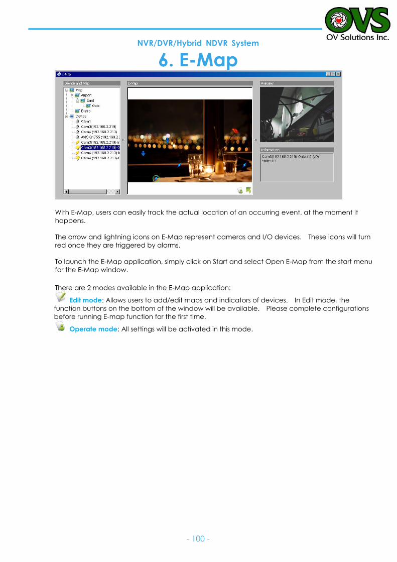
NVR/DVR/Hybrid NDVR System
- 100 -
6. E-Map
With E-Map, users can easily track the actual location of an occurring event, at the moment it
happens.
The arrow and lightning icons on E-Map represent cameras and I/O devices. These icons will turn
red once they are triggered by alarms.
To launch the E-Map application, simply click on Start and select Open E-Map from the start menu
for the E-Map window.
There are 2 modes available in the E-Map application:
Edit mode: Allows users to add/edit maps and indicators of devices. In Edit mode, the
function buttons on the bottom of the window will be available. Please complete configurations
before running E-map function for the first time.
Operate mode: All settings will be activated in this mode.
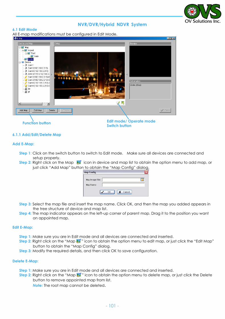
NVR/DVR/Hybrid NDVR System
- 101 -
Edit mode/ Operate mode Switch button
Function button
6.1 Edit Mode
All E-map modifications must be configured in Edit Mode.
6.1.1 Add/Edit/Delete Map
Add E-Map:
Step 1: Click on the switch button to switch to Edit mode. Make sure all devices are connected and
setup properly.
Step 2: Right click on the Map icon in device and map list to obtain the option menu to add map, or
just click “Add Map” button to obtain the “Map Config” dialog.
Step 3: Select the map file and insert the map name. Click OK, and then the map you added appears in
the tree structure of device and map list.
Step 4: The map indicator appears on the left-up corner of parent map. Drag it to the position you want
on appointed map.
Edit E-Map:
Step 1: Make sure you are in Edit mode and all devices are connected and inserted.
Step 2: Right click on the “Map ” icon to obtain the option menu to edit map, or just click the “Edit Map”
button to obtain the “Map Config” dialog.
Step 3: Modify the required details, and then click OK to save configuration.
Delete E-Map:
Step 1: Make sure you are in Edit mode and all devices are connected and inserted.
Step 2: Right click on the “Map ” icon to obtain the option menu to delete map, or just click the Delete
button to remove appointed map from list.
Note: The root map cannot be deleted.
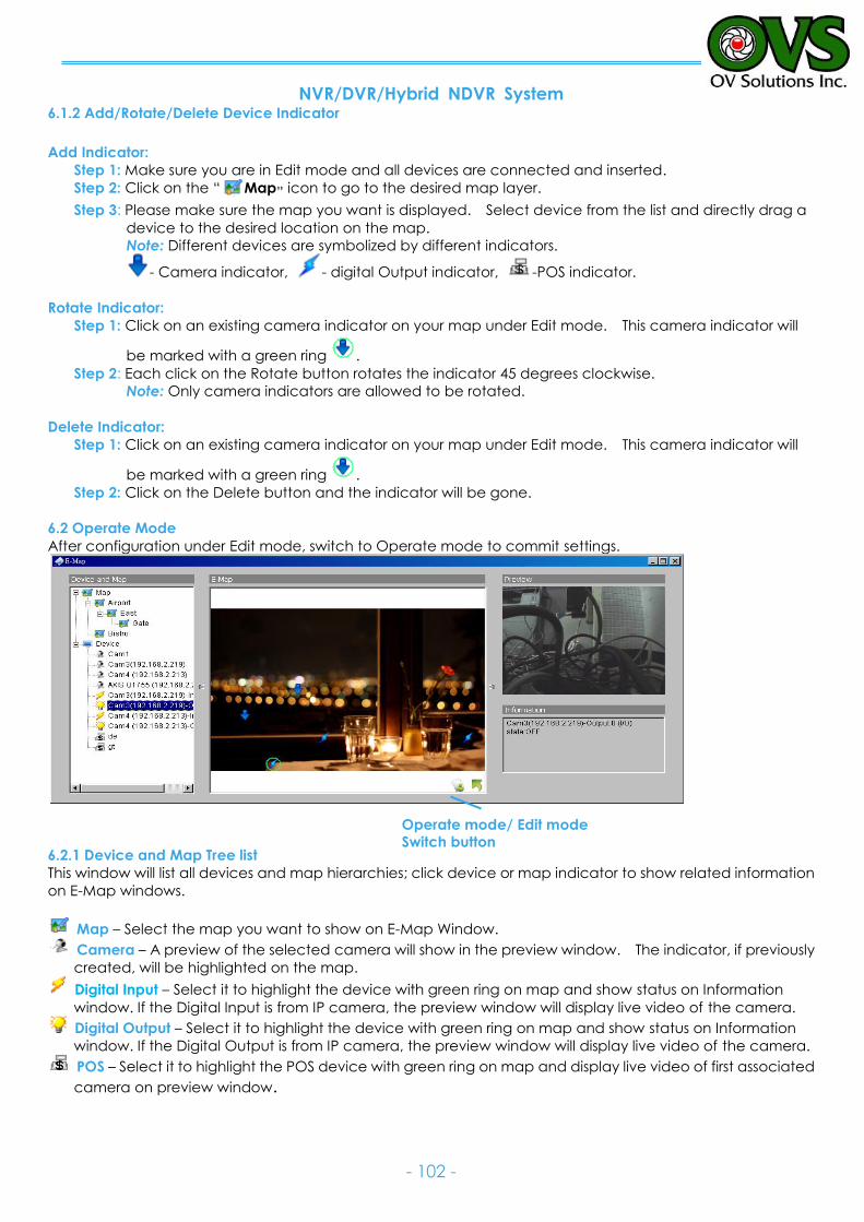
NVR/DVR/Hybrid NDVR System
- 102 -
Operate mode/ Edit mode Switch button
6.1.2 Add/Rotate/Delete Device Indicator
Add Indicator:
Step 1: Make sure you are in Edit mode and all devices are connected and inserted.
Step 2: Click on the “ Map” icon to go to the desired map layer.
Step 3: Please make sure the map you want is displayed. Select device from the list and directly drag a
device to the desired location on the map.
Note: Different devices are symbolized by different indicators.
- Camera indicator, - digital Output indicator, -POS indicator.
Rotate Indicator:
Step 1: Click on an existing camera indicator on your map under Edit mode. This camera indicator will
be marked with a green ring .
Step 2: Each click on the Rotate button rotates the indicator 45 degrees clockwise.
Note: Only camera indicators are allowed to be rotated.
Delete Indicator:
Step 1: Click on an existing camera indicator on your map under Edit mode. This camera indicator will
be marked with a green ring .
Step 2: Click on the Delete button and the indicator will be gone.
6.2 Operate Mode
After configuration under Edit mode, switch to Operate mode to commit settings.
6.2.1 Device and Map Tree list
This window will list all devices and map hierarchies; click device or map indicator to show related information
on E-Map windows.
Map – Select the map you want to show on E-Map Window.
Camera – A preview of the selected camera will show in the preview window. The indicator, if previously
created, will be highlighted on the map.
Digital Input – Select it to highlight the device with green ring on map and show status on Information
window. If the Digital Input is from IP camera, the preview window will display live video of the camera.
Digital Output – Select it to highlight the device with green ring on map and show status on Information
window. If the Digital Output is from IP camera, the preview window will display live video of the camera.
POS – Select it to highlight the POS device with green ring on map and display live video of first associated
camera on preview window.
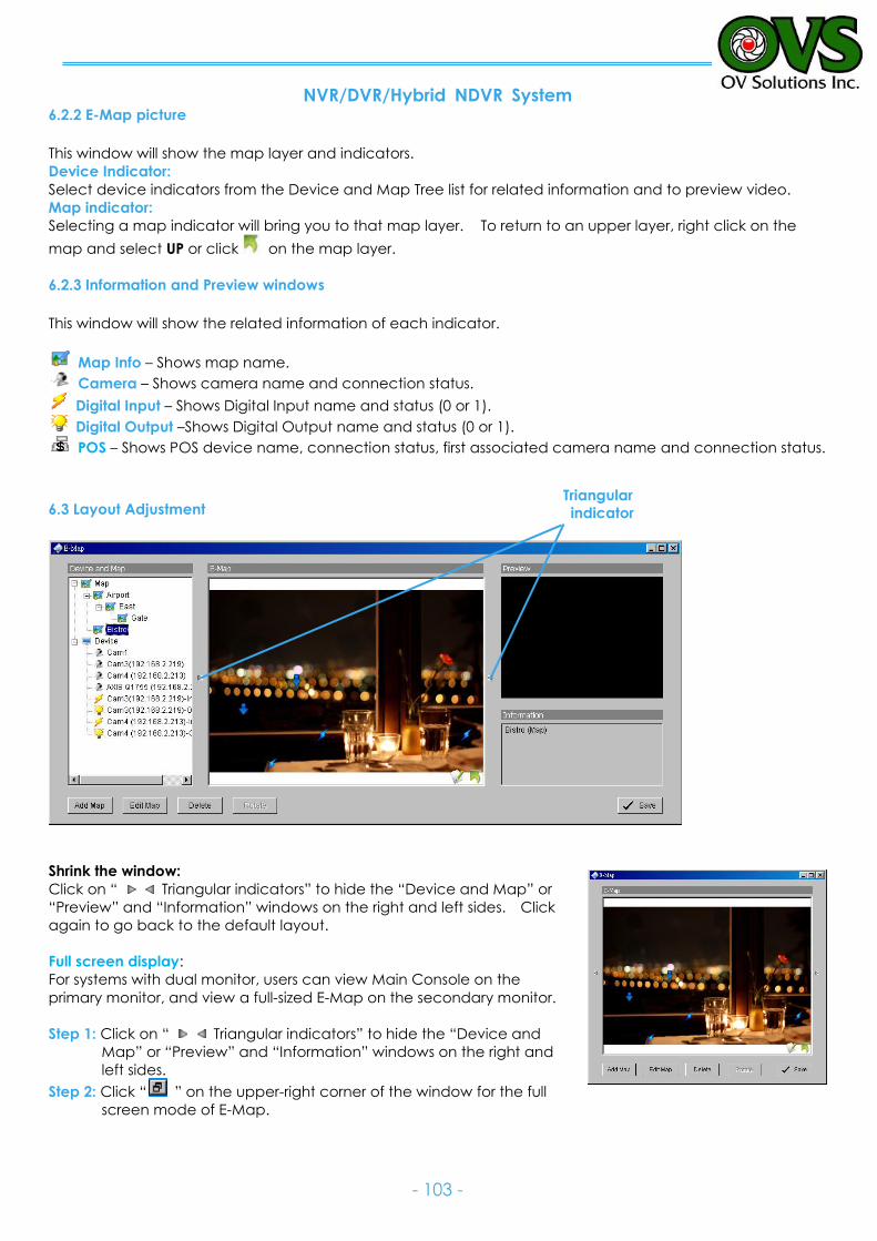
NVR/DVR/Hybrid NDVR System
- 103 -
Triangular
indicator
6.2.2 E-Map picture
This window will show the map layer and indicators.
Device Indicator:
Select device indicators from the Device and Map Tree list for related information and to preview video.
Map indicator:
Selecting a map indicator will bring you to that map layer. To return to an upper layer, right click on the
map and select UP or click on the map layer.
6.2.3 Information and Preview windows
This window will show the related information of each indicator.
Map Info – Shows map name.
Camera – Shows camera name and connection status.
Digital Input – Shows Digital Input name and status (0 or 1).
Digital Output –Shows Digital Output name and status (0 or 1).
POS – Shows POS device name, connection status, first associated camera name and connection status.
6.3 Layout Adjustment
Shrink the window:
Click on “ Triangular indicators” to hide the “Device and Map” or
“Preview” and “Information” windows on the right and left sides. Click
again to go back to the default layout.
Full screen display:
For systems with dual monitor, users can view Main Console on the
primary monitor, and view a full-sized E-Map on the secondary monitor.
Step 1: Click on “ Triangular indicators” to hide the “Device and
Map” or “Preview” and “Information” windows on the right and
left sides.
Step 2: Click “ ” on the upper-right corner of the window for the full
screen mode of E-Map.
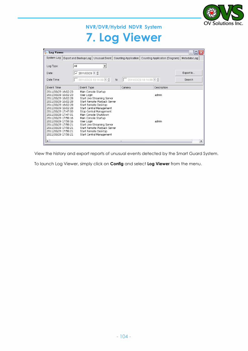
NVR/DVR/Hybrid NDVR System
- 104 -
7. Log Viewer
View the history and export reports of unusual events detected by the Smart Guard System.
To launch Log Viewer, simply click on Config and select Log Viewer from the menu.
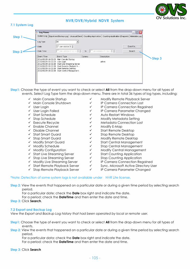
NVR/DVR/Hybrid NDVR System
- 105 -
7.1 System Log
Step1: Choose the type of event you want to check or select All from the drop-down menu for all types of
events. Select Log Type form the drop-down menu. There are in total 36 types of log types, including:
*Note: Detection of some system logs is not available under NVR Lite license.
Step 2: View the events that happened on a particular date or during a given time period by selecting search
period.
For a particular date: check the Date box right and indicate the date.
For a period: check the DateTime and then enter the date and time.
Step 3: Click Search.
7.2 Export and Backup Log
View the Export and Backup Log history that had been operated by local or remote user.
Step1: Choose the type of event you want to check or select All from the drop-down menu for all types of
events.
Step 2: View the events that happened on a particular date or during a given time period by selecting search
period.
For a particular data: check the Date box right and indicate the date.
For a period: check the DateTime and then enter the date and time.
Step 3: Click Search
Main Console Startup
Main Console Shutdown
User Login
User Login Failed
Start Schedule
Stop Schedule
Execute Recycle
Enable Channel
Disable Channel
Start Smart Guard
Stop Smart Guard
Modify Smart Guard
Modify Schedule
Modify Configuration
Start Live Streaming Server
Stop Live Streaming Server
Modify Live Streaming Server
Start Remote Playback Server
Stop Remote Playback Server
Modify Remote Playback Server
IP Camera Connection Lost
IP Camera Connection Regained
IP Camera Parameter Changed
Auto Restart Windows
Modify Metadata Setting
Metadata Connection Lost
Modify E-Map
Start Remote Desktop
Stop Remote Desktop
Modify Remote Desktop
Start Central Management
Stop Central Management
Modify Central Management
Start Counting Application
Stop Counting Application
IP Camera Connection Regained
Sync. Microsoft Active Directory User
IP Camera Parameter Changed
Step 3
Step 1
Step 2
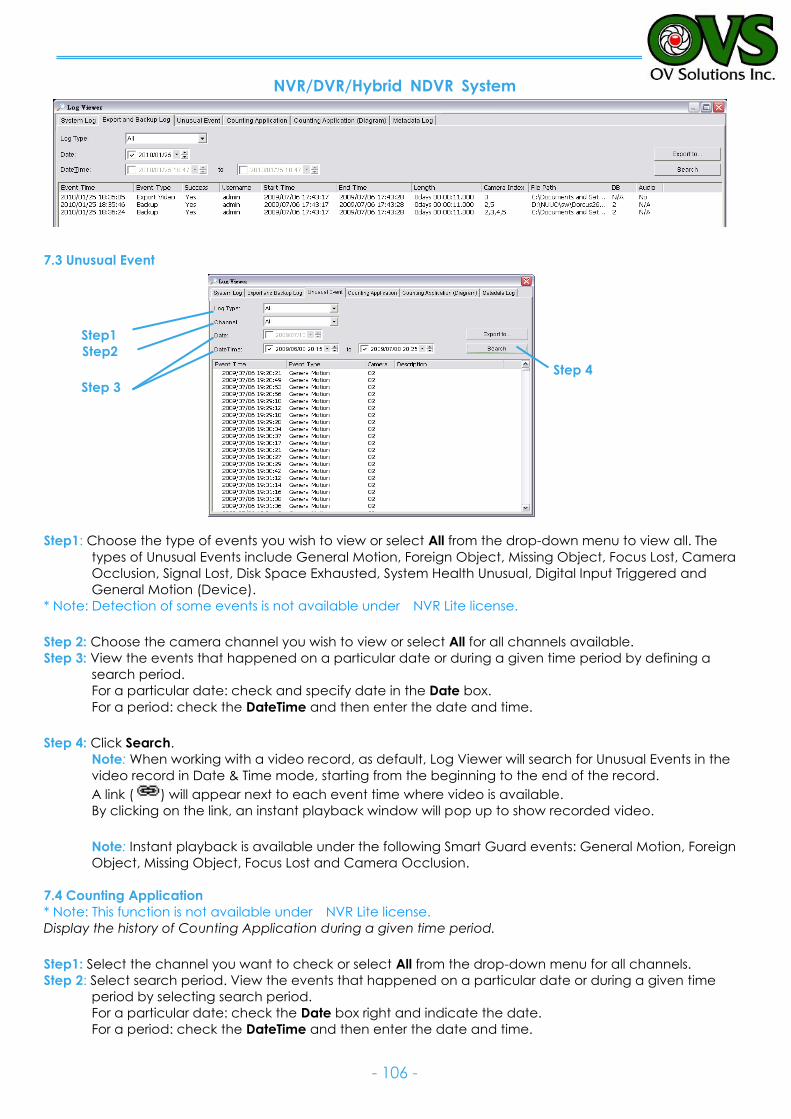
NVR/DVR/Hybrid NDVR System
- 106 -
7.3 Unusual Event
Step1
Step2
Step 3
Step1: Choose the type of events you wish to view or select All from the drop-down menu to view all. The
types of Unusual Events include General Motion, Foreign Object, Missing Object, Focus Lost, Camera
Occlusion, Signal Lost, Disk Space Exhausted, System Health Unusual, Digital Input Triggered and
General Motion (Device).
* Note: Detection of some events is not available under NVR Lite license.
Step 2: Choose the camera channel you wish to view or select All for all channels available.
Step 3: View the events that happened on a particular date or during a given time period by defining a
search period.
For a particular date: check and specify date in the Date box.
For a period: check the DateTime and then enter the date and time.
Step 4: Click Search.
Note: When working with a video record, as default, Log Viewer will search for Unusual Events in the
video record in Date & Time mode, starting from the beginning to the end of the record.
A link ( ) will appear next to each event time where video is available.
By clicking on the link, an instant playback window will pop up to show recorded video.
Note: Instant playback is available under the following Smart Guard events: General Motion, Foreign
Object, Missing Object, Focus Lost and Camera Occlusion.
7.4 Counting Application
* Note: This function is not available under NVR Lite license.
Display the history of Counting Application during a given time period.
Step1: Select the channel you want to check or select All from the drop-down menu for all channels.
Step 2: Select search period. View the events that happened on a particular date or during a given time
period by selecting search period.
For a particular date: check the Date box right and indicate the date.
For a period: check the DateTime and then enter the date and time.
Step 4
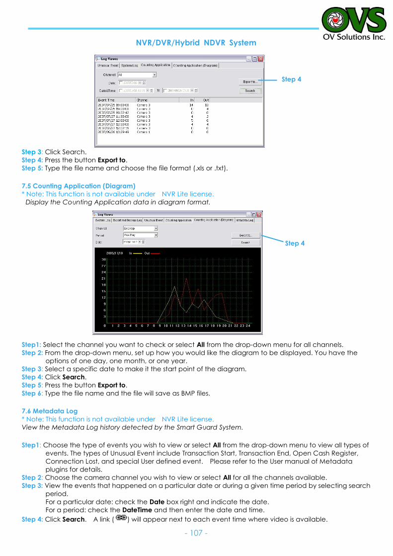
NVR/DVR/Hybrid NDVR System
- 107 -
Step 3: Click Search.
Step 4: Press the button Export to.
Step 5: Type the file name and choose the file format (.xls or .txt).
7.5 Counting Application (Diagram)
* Note: This function is not available under NVR Lite license.
Display the Counting Application data in diagram format.
Step1: Select the channel you want to check or select All from the drop-down menu for all channels.
Step 2: From the drop-down menu, set up how you would like the diagram to be displayed. You have the
options of one day, one month, or one year.
Step 3: Select a specific date to make it the start point of the diagram.
Step 4: Click Search.
Step 5: Press the button Export to.
Step 6: Type the file name and the file will save as BMP files.
7.6 Metadata Log
* Note: This function is not available under NVR Lite license.
View the Metadata Log history detected by the Smart Guard System.
Step1: Choose the type of events you wish to view or select All from the drop-down menu to view all types of
events. The types of Unusual Event include Transaction Start, Transaction End, Open Cash Register,
Connection Lost, and special User defined event. Please refer to the User manual of Metadata
plugins for details.
Step 2: Choose the camera channel you wish to view or select All for all the channels available.
Step 3: View the events that happened on a particular date or during a given time period by selecting search
period.
For a particular date: check the Date box right and indicate the date.
For a period: check the DateTime and then enter the date and time.
Step 4: Click Search. A link ( ) will appear next to each event time where video is available.
Step 4
Step 4
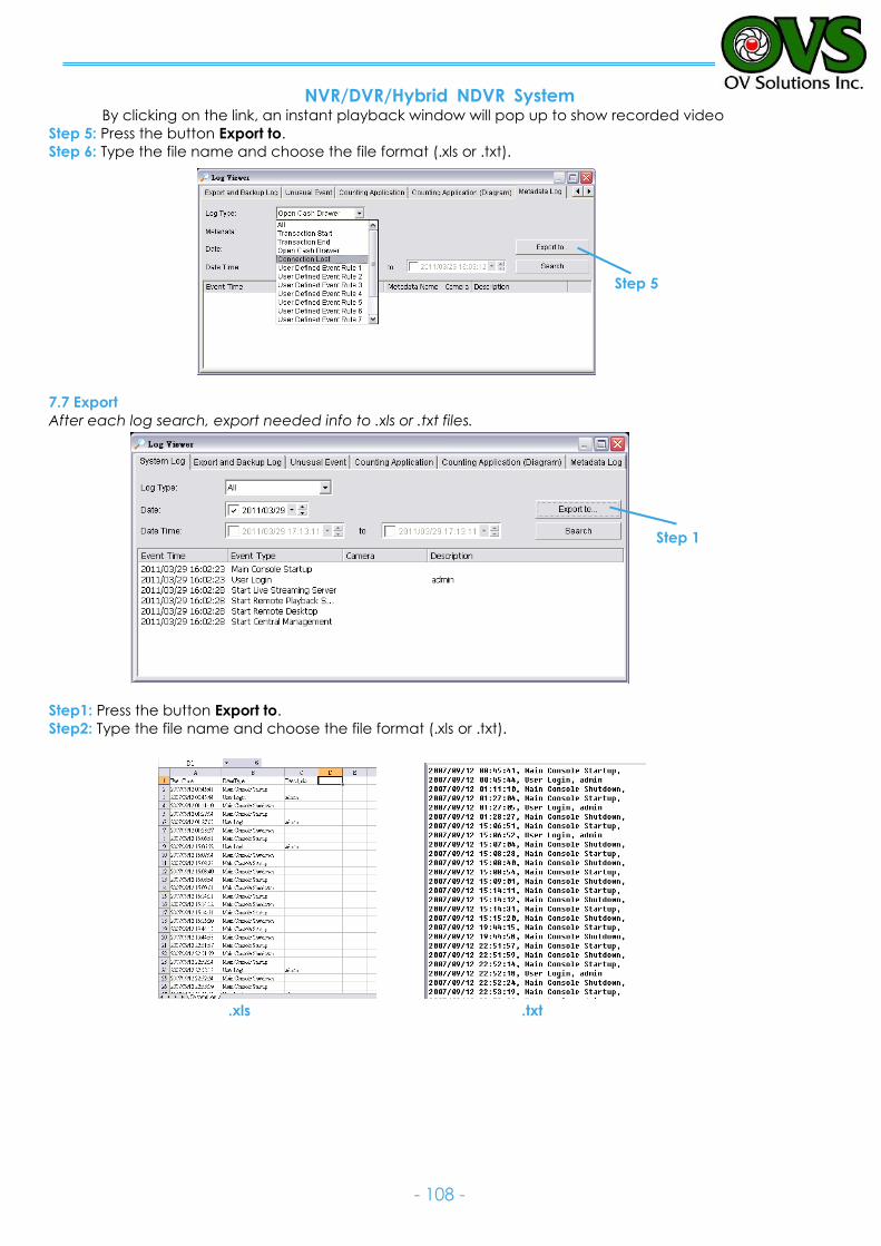
NVR/DVR/Hybrid NDVR System
- 108 -
By clicking on the link, an instant playback window will pop up to show recorded video
Step 5: Press the button Export to.
Step 6: Type the file name and choose the file format (.xls or .txt).
7.7 Export
After each log search, export needed info to .xls or .txt files.
Step1: Press the button Export to.
Step2: Type the file name and choose the file format (.xls or .txt).
Step 1
.xls .txt
Step 5
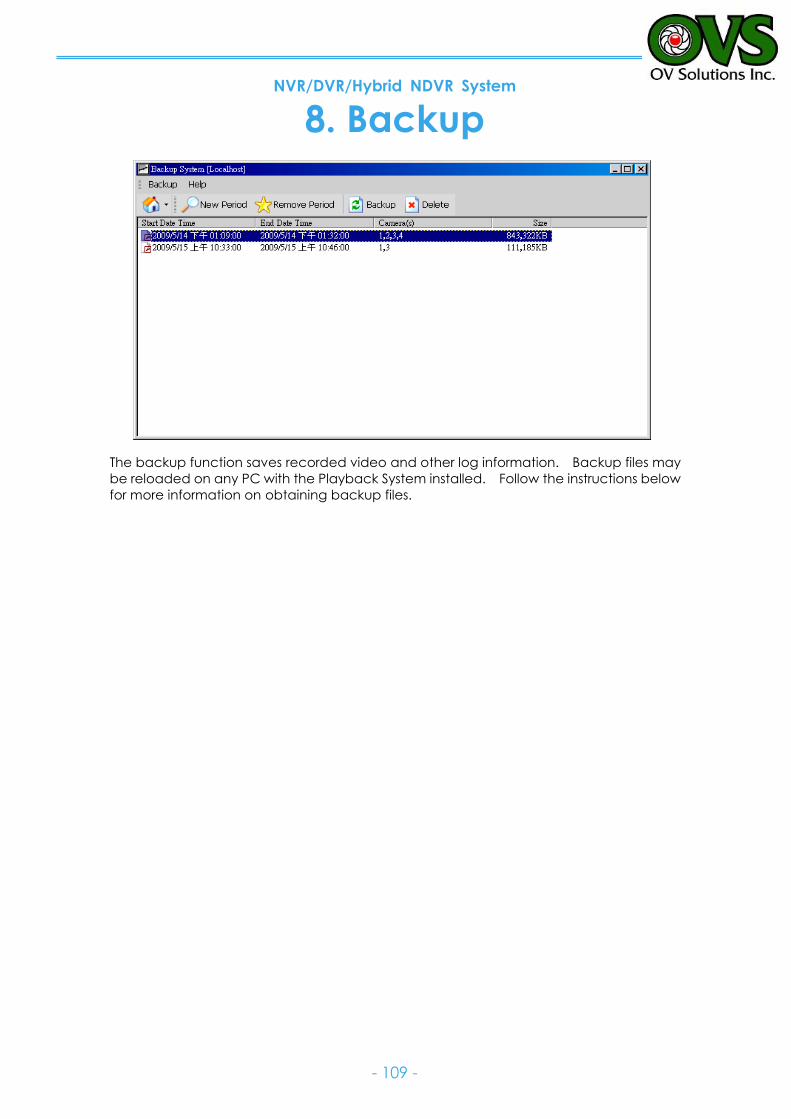
NVR/DVR/Hybrid NDVR System
- 109 -
8. Backup
The backup function saves recorded video and other log information. Backup files may
be reloaded on any PC with the Playback System installed. Follow the instructions below
for more information on obtaining backup files.
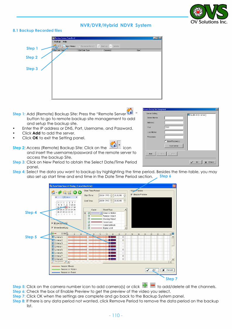
NVR/DVR/Hybrid NDVR System
- 110 -
8.1 Backup Recorded files
Step 1: Add (Remote) Backup Site: Press the “Remote Server ”
button to go to remote backup site management to add
and setup the backup site.
Enter the IP address or DNS, Port, Username, and Password.
Click Add to add the server.
Click OK to exit the Setting panel.
Step 2: Access (Remote) Backup Site: Click on the icon
and insert the username/password of the remote server to
access the backup Site.
Step 3: Click on New Period to obtain the Select Date/Time Period
panel.
Step 4: Select the data you want to backup by highlighting the time period. Besides the time-table, you may
also set up start time and end time in the Date Time Period section.
Step 5: Click on the camera number icon to add camera(s) or click to add/delete all the channels.
Step 6: Check the box of Enable Preview to get the preview of the video you select.
Step 7: Click OK when the settings are complete and go back to the Backup System panel.
Step 8: If there is any data period not wanted, click Remove Period to remove the data period on the backup
list.
Step 3
Step 1
Step 2
Step 4
Step 5
Step 7
Step 6
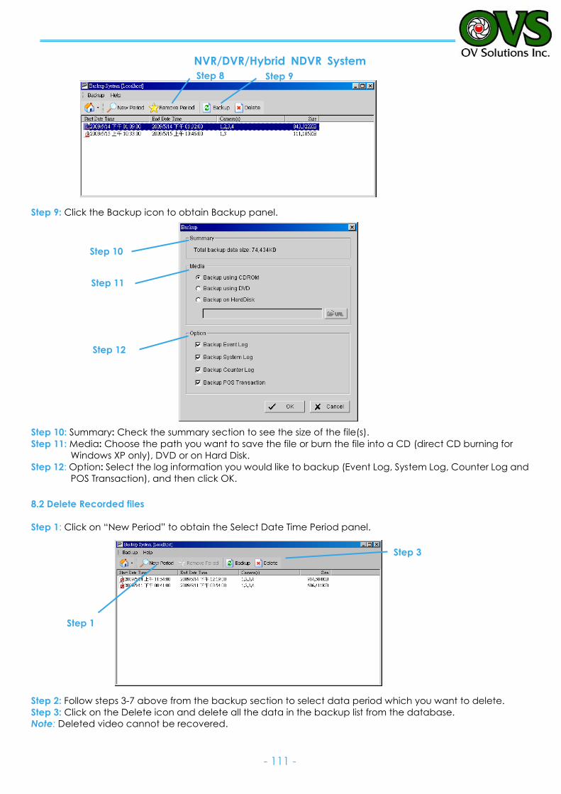
NVR/DVR/Hybrid NDVR System
- 111 -
Step 9: Click the Backup icon to obtain Backup panel.
Step 10: Summary: Check the summary section to see the size of the file(s).
Step 11: Media: Choose the path you want to save the file or burn the file into a CD (direct CD burning for
Windows XP only), DVD or on Hard Disk.
Step 12: Option: Select the log information you would like to backup (Event Log, System Log, Counter Log and
POS Transaction), and then click OK.
8.2 Delete Recorded files
Step 1: Click on “New Period” to obtain the Select Date Time Period panel.
Step 2: Follow steps 3-7 above from the backup section to select data period which you want to delete.
Step 3: Click on the Delete icon and delete all the data in the backup list from the database.
Note: Deleted video cannot be recovered.
Step 12
Step 11
Step 10
Step 1
Step 3
Step 8 Step 9
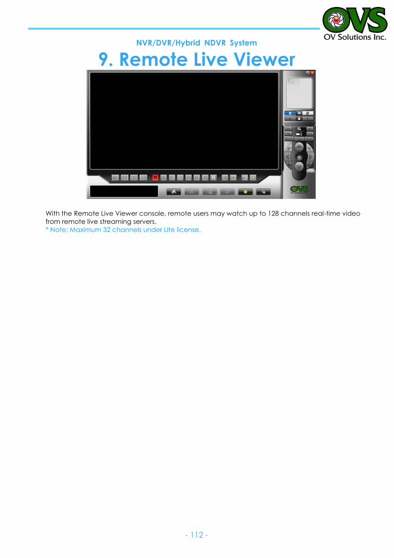
NVR/DVR/Hybrid NDVR System
- 112 -
9. Remote Live Viewer
With the Remote Live Viewer console, remote users may watch up to 128 channels real-time video
from remote live streaming servers.
* Note: Maximum 32 channels under Lite license.
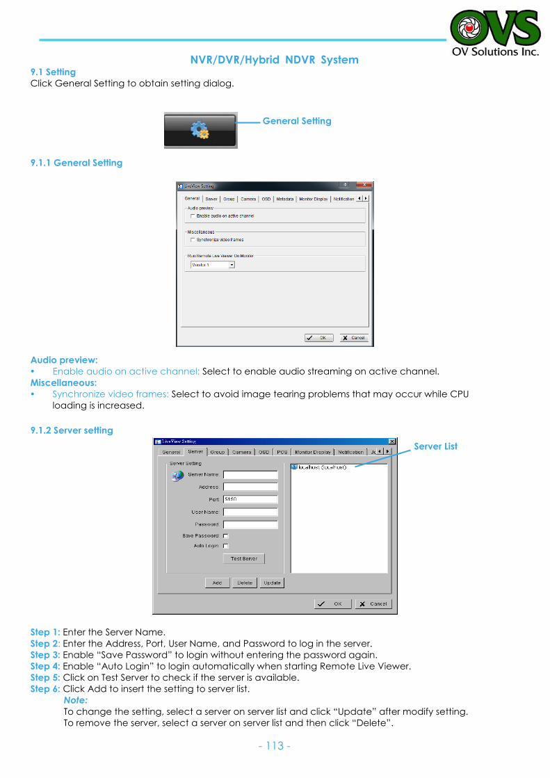
NVR/DVR/Hybrid NDVR System
- 113 -
Server List
General Setting
9.1 Setting
Click General Setting to obtain setting dialog.
9.1.1 General Setting
Audio preview:
Enable audio on active channel: Select to enable audio streaming on active channel.
Miscellaneous:
Synchronize video frames: Select to avoid image tearing problems that may occur while CPU
loading is increased.
9.1.2 Server setting
Step 1: Enter the Server Name.
Step 2: Enter the Address, Port, User Name, and Password to log in the server.
Step 3: Enable “Save Password” to login without entering the password again.
Step 4: Enable “Auto Login” to login automatically when starting Remote Live Viewer.
Step 5: Click on Test Server to check if the server is available.
Step 6: Click Add to insert the setting to server list.
Note:
To change the setting, select a server on server list and click “Update” after modify setting.
To remove the server, select a server on server list and then click “Delete”.
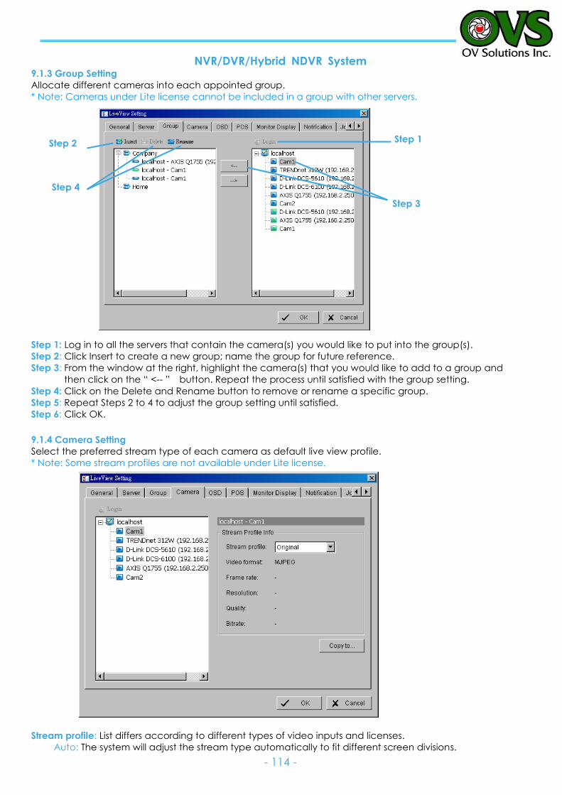
NVR/DVR/Hybrid NDVR System
- 114 -
9.1.3 Group Setting
Allocate different cameras into each appointed group.
* Note: Cameras under Lite license cannot be included in a group with other servers.
Step 1: Log in to all the servers that contain the camera(s) you would like to put into the group(s).
Step 2: Click Insert to create a new group; name the group for future reference.
Step 3: From the window at the right, highlight the camera(s) that you would like to add to a group and
then click on the “ <-- ” button. Repeat the process until satisfied with the group setting.
Step 4: Click on the Delete and Rename button to remove or rename a specific group.
Step 5: Repeat Steps 2 to 4 to adjust the group setting until satisfied.
Step 6: Click OK.
9.1.4 Camera Setting
Select the preferred stream type of each camera as default live view profile.
* Note: Some stream profiles are not available under Lite license.
Stream profile: List differs according to different types of video inputs and licenses.
Auto: The system will adjust the stream type automatically to fit different screen divisions.
Step 1 Step 2
Step 3
Step 4
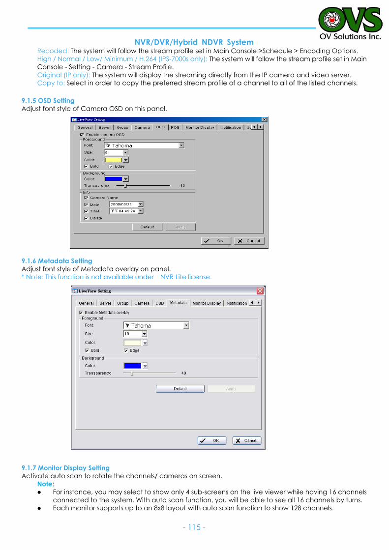
NVR/DVR/Hybrid NDVR System
- 115 -
Recoded: The system will follow the stream profile set in Main Console >Schedule > Encoding Options.
High / Normal / Low/ Minimum / H.264 (IPS-7000s only): The system will follow the stream profile set in Main
Console - Setting - Camera - Stream Profile.
Original (IP only): The system will display the streaming directly from the IP camera and video server.
Copy to: Select in order to copy the preferred stream profile of a channel to all of the listed channels.
9.1.5 OSD Setting
Adjust font style of Camera OSD on this panel.
9.1.6 Metadata Setting
Adjust font style of Metadata overlay on panel.
* Note: This function is not available under NVR Lite license.
9.1.7 Monitor Display Setting
Activate auto scan to rotate the channels/ cameras on screen.
Note:
For instance, you may select to show only 4 sub-screens on the live viewer while having 16 channels
connected to the system. With auto scan function, you will be able to see all 16 channels by turns.
Each monitor supports up to an 8x8 layout with auto scan function to show 128 channels.
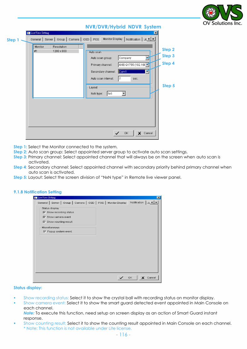
NVR/DVR/Hybrid NDVR System
- 116 -
Step 1: Select the Monitor connected to the system.
Step 2: Auto scan group: Select appointed server group to activate auto scan settings.
Step 3: Primary channel: Select appointed channel that will always be on the screen when auto scan is
activated.
Step 4: Secondary channel: Select appointed channel with secondary priority behind primary channel when
auto scan is activated.
Step 5: Layout: Select the screen division of “NxN type” in Remote live viewer panel.
9.1.8 Notification Setting
Status display:
Show recording status: Select it to show the crystal ball with recording status on monitor display.
Show camera event: Select it to show the smart guard detected event appointed in Main Console on
each channel.
Note: To execute this function, need setup on screen display as an action of Smart Guard instant
response.
Show counting result: Select it to show the counting result appointed in Main Console on each channel.
* Note: This function is not available under Lite license.
Step 1
Step 2
Step 3
Step 4
Step 5
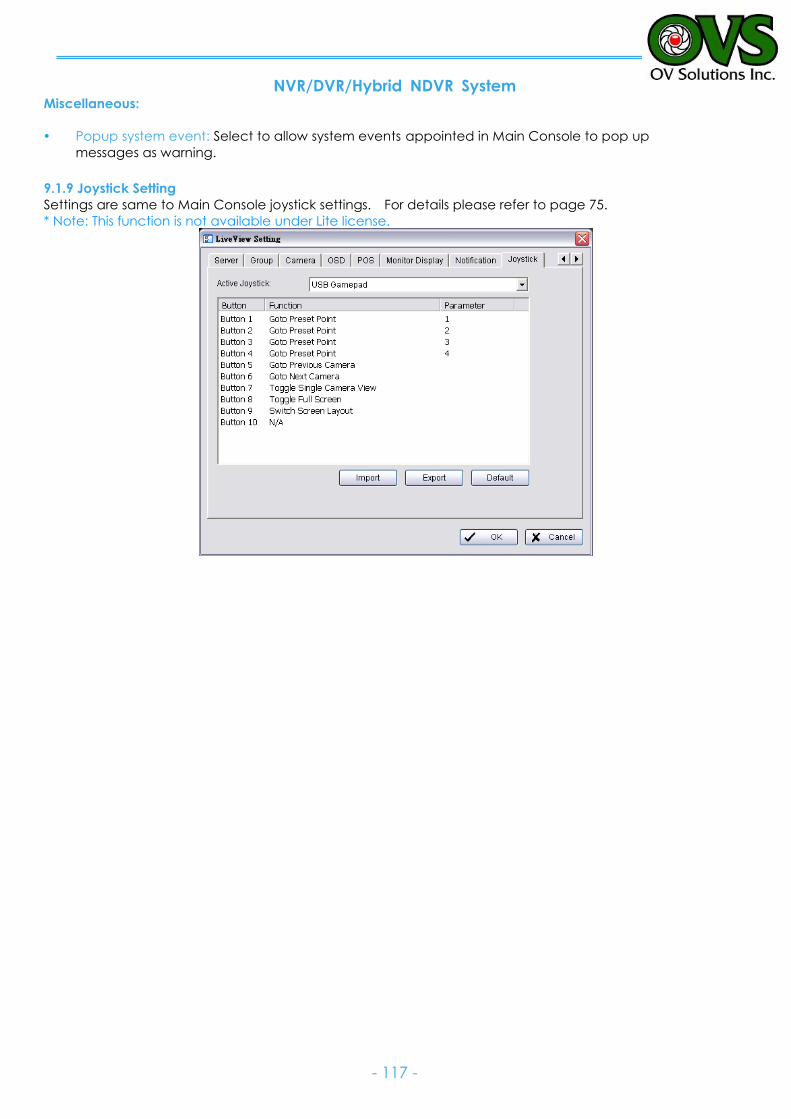
NVR/DVR/Hybrid NDVR System
- 117 -
Miscellaneous:
Popup system event: Select to allow system events appointed in Main Console to pop up
messages as warning.
9.1.9 Joystick Setting
Settings are same to Main Console joystick settings. For details please refer to page 75.
* Note: This function is not available under Lite license.
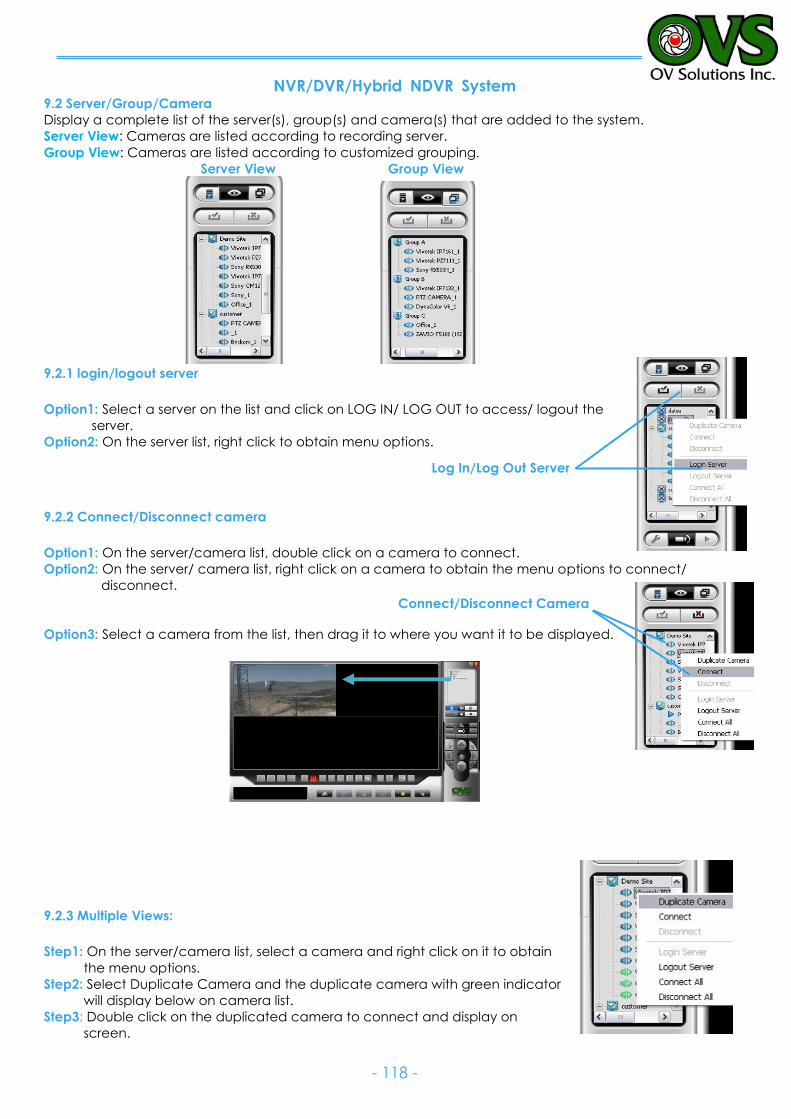
NVR/DVR/Hybrid NDVR System
- 118 -
Log In/Log Out Server
Connect/Disconnect Camera
9.2 Server/Group/Camera
Display a complete list of the server(s), group(s) and camera(s) that are added to the system.
Server View: Cameras are listed according to recording server.
Group View: Cameras are listed according to customized grouping.
Server View Group View
9.2.1 login/logout server
Option1: Select a server on the list and click on LOG IN/ LOG OUT to access/ logout the
server.
Option2: On the server list, right click to obtain menu options.
9.2.2 Connect/Disconnect camera
Option1: On the server/camera list, double click on a camera to connect.
Option2: On the server/ camera list, right click on a camera to obtain the menu options to connect/
disconnect.
Option3: Select a camera from the list, then drag it to where you want it to be displayed.
9.2.3 Multiple Views:
Step1: On the server/camera list, select a camera and right click on it to obtain
the menu options.
Step2: Select Duplicate Camera and the duplicate camera with green indicator
will display below on camera list.
Step3: Double click on the duplicated camera to connect and display on
screen.
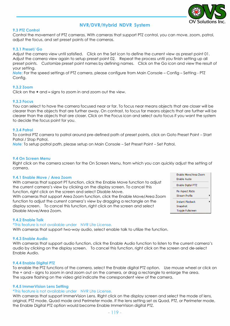
NVR/DVR/Hybrid NDVR System
- 119 -
9.3 PTZ Control
Control the movement of PTZ cameras. With cameras that support PTZ control, you can move, zoom, patrol,
adjust the focus, and set preset points of the cameras.
9.3.1 Preset/ Go
Adjust the camera view until satisfied. Click on the Set icon to define the current view as preset point 01.
Adjust the camera view again to setup preset point 02. Repeat the process until you finish setting up all
preset points. Customize preset point names by defining names. Click on the Go icon and view the result of
your setting.
Note: For the speed settings of PTZ camera, please configure from Main Console – Config – Setting - PTZ
Config.
9.3.2 Zoom
Click on the + and – signs to zoom in and zoom out the view.
9.3.3 Focus
You can select to have the camera focused near or far. To focus near means objects that are closer will be
clearer than the objects that are further away. On contrast, to focus far means objects that are further will be
clearer than the objects that are closer. Click on the Focus icon and select auto focus if you want the system
to decide the focus point for you.
9.3.4 Patrol
To control PTZ camera to patrol around pre-defined path of preset points, click on Goto Preset Point – Start
Patrol / Stop Patrol.
Note: To setup patrol path, please setup on Main Console – Set Preset Point – Set Patrol.
9.4 On Screen Menu
Right click on the camera screen for the On Screen Menu, from which you can quickly adjust the setting of
camera.
9.4.1 Enable Move / Area Zoom
With cameras that support PT function, click the Enable Move function to adjust
the current camera’s view by clicking on the display screen. To cancel this
function, right click on the screen and select Disable Move.
With cameras that support Area Zoom function, click the Enable Move/Area Zoom
function to adjust the current camera’s view by dragging a rectangle on the
display screen. To cancel this function, right click on the screen and select
Disable Move/Area Zoom.
9.4.2 Enable Talk
*This feature is not available under NVR Lite License.
With cameras that support two-way audio, select enable talk to utilize the function.
9.4.3 Enable Audio
With cameras that support audio function, click the Enable Audio function to listen to the current camera’s
audio by clicking on the display screen. To cancel this function, right click on the screen and de-select
Enable Audio. 9.4.4 Enable Digital PTZ
To enable the PTZ functions of the camera, select the Enable digital PTZ option. Use mouse wheel or click on
the + and – signs to zoom in and zoom out on the camera, or drag a rectangle to enlarge the area.
The square flashing on the video grid indicate the correspondent view of the camera.
9.4.5 ImmerVision Lens Setting
*This feature is not available under NVR Lite License.
With cameras that support ImmerVision Lens. Right click on the display screen and select the mode of lens,
original, PTZ mode, Quad mode and Perimeter mode. If the lens setting set as Quad, PTZ, or Perimeter mode,
the Enable Digital PTZ option would become Enable ImmerVision digital PTZ.
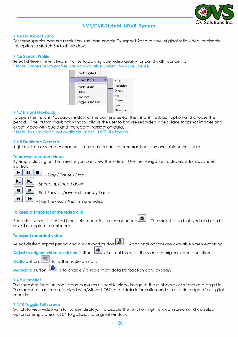
NVR/DVR/Hybrid NDVR System
- 120 -
9.4.6 Fix Aspect Ratio
For some special camera resolution, user can enable Fix Aspect Ratio to view original ratio video, or disable
this option to stretch 3:4 to fit window.
9.4.6 Stream Profile
Select different level Stream Profiles to downgrade video quality for bandwidth concerns. * Note: Some stream profiles are not available under NVR Lite license.
9.4.7 Instant Playback
To open the Instant Playback window of the camera, select the Instant Playback option and choose the
period. The instant playback window allows the user to browse recorded video, take snapshot images and
export video with audio and metadata transaction data.
* Note: This function is not available under NVR Lite license.
9.4.8 Duplicate Camera
Right click on any empty channel. You may duplicate cameras from any available servers here.
To browse recorded video
By simply clicking on the timeline you can view the video. Use the navigation tools below for advanced
control.
- Play / Pause / Stop
- Speed up/Speed down
- Fast Forward/reverse frame by frame
- Play Previous / Next minute video
To keep a snapshot of the video clip
Pause the video at desired time point and click snapshot button . The snapshot is displayed and can be
saved or copied to clipboard.
To export recorded video
Select desired export period and click export button . Additional options are available when exporting.
Adjust to original video resolution button is the tool to adjust the video to original video resolution.
Audio button turns the audio on / off.
Metadata button is to enable / disable metadata transaction data overlay.
9.4.9 Snapshot
The snapshot function copies and captures a specific video image to the clipboard or to save as a bmp file.
The snapshot can be customized with/without OSD, metadata information and selectable range after digital
zoom in.
9.4.10 Toggle Full screen
Switch to view video with full screen display. To disable the function, right click on screen and de-select
option or simply press “ESC” to go back to original window.
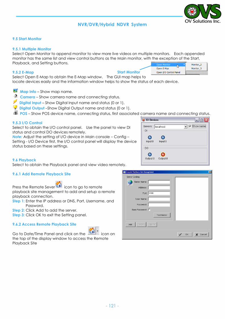
NVR/DVR/Hybrid NDVR System
- 121 -
Start Monitor
9.5 Start Monitor
9.5.1 Multiple Monitor
Select Open Monitor to append monitor to view more live videos on multiple monitors. Each appended
monitor has the same list and view control buttons as the Main monitor, with the exception of the Start,
Playback, and Setting buttons.
9.5.2 E-Map
Select Open E-Map to obtain the E-Map window. The GUI map helps to
locate devices easily and the information window helps to show the status of each device.
Map Info – Show map name.
Camera – Show camera name and connecting status.
Digital Input – Show Digital Input name and status (0 or 1).
Digital Output –Show Digital Output name and status (0 or 1).
POS – Show POS device name, connecting status, first associated camera name and connecting status.
9.5.3 I/O Control
Select to obtain the I/O control panel. Use the panel to view DI
status and control DO devices remotely.
Note: Adjust the setting of I/O device in Main console – Config –
Setting - I/O Device first, the I/O control panel will display the device
status based on these settings.
9.6 Playback
Select to obtain the Playback panel and view video remotely.
9.6.1 Add Remote Playback Site
Press the Remote Sever icon to go to remote
playback site management to add and setup a remote
playback connection.
Step 1: Enter the IP address or DNS, Port, Username, and
Password.
Step 2: Click Add to add the server.
Step 3: Click OK to exit the Setting panel.
9.6.2 Access Remote Playback Site
Go to Date/Time Panel and click on the icon on
the top of the display window to access the Remote
Playback Site

NVR/DVR/Hybrid NDVR System
- 122 -
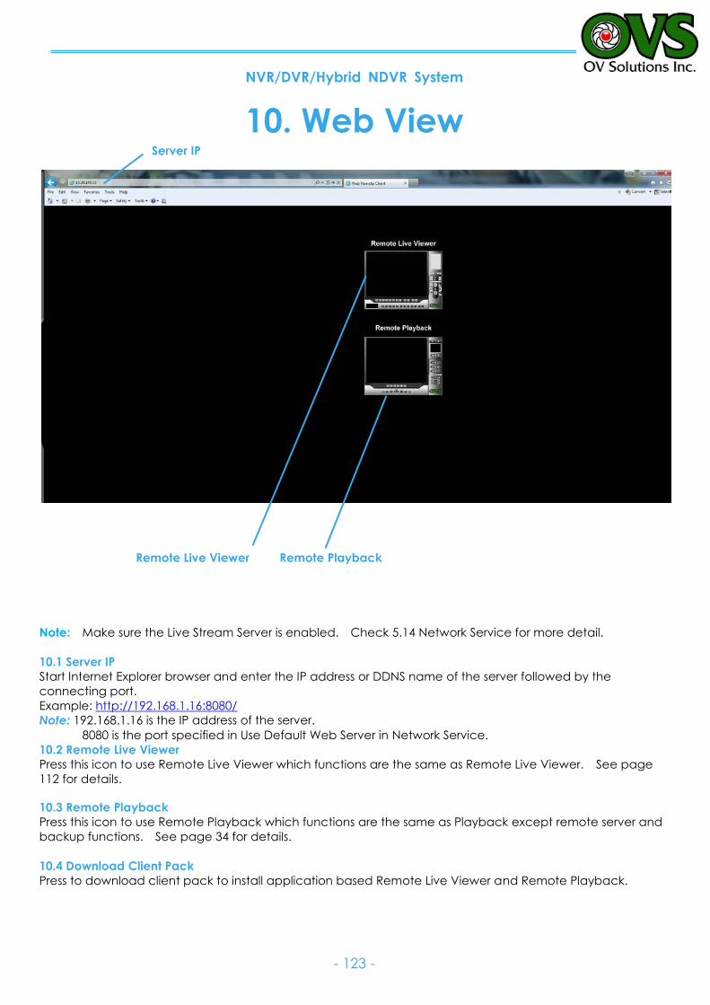
NVR/DVR/Hybrid NDVR System
- 123 -
10. Web View
Note: Make sure the Live Stream Server is enabled. Check 5.14 Network Service for more detail.
10.1 Server IP
Start Internet Explorer browser and enter the IP address or DDNS name of the server followed by the
connecting port.
Example: http://192.168.1.16:8080/
Note: 192.168.1.16 is the IP address of the server.
8080 is the port specified in Use Default Web Server in Network Service.
10.2 Remote Live Viewer
Press this icon to use Remote Live Viewer which functions are the same as Remote Live Viewer. See page
112 for details.
10.3 Remote Playback
Press this icon to use Remote Playback which functions are the same as Playback except remote server and
backup functions. See page 34 for details.
10.4 Download Client Pack
Press to download client pack to install application based Remote Live Viewer and Remote Playback.
Remote Live Viewer
Remote Playback
Server IP

NVR/DVR/Hybrid NDVR System
- 124 -
11. Utilities
A. Verification Tool
B. License Management Tool
C. Resource Management Tool
D. DB Tool
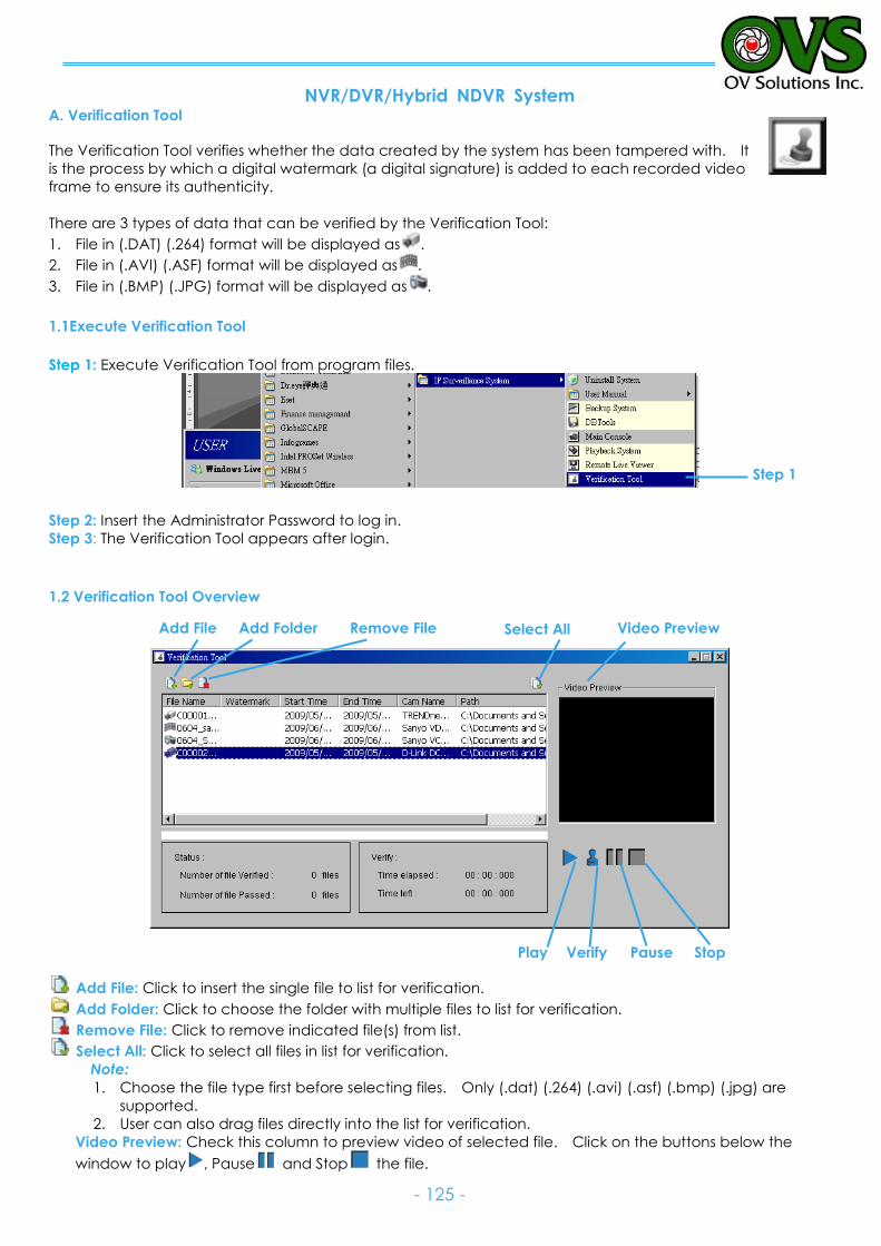
NVR/DVR/Hybrid NDVR System
- 125 -
A. Verification Tool
The Verification Tool verifies whether the data created by the system has been tampered with. It
is the process by which a digital watermark (a digital signature) is added to each recorded video
frame to ensure its authenticity.
There are 3 types of data that can be verified by the Verification Tool:
1. File in (.DAT) (.264) format will be displayed as .
2. File in (.AVI) (.ASF) format will be displayed as .
3. File in (.BMP) (.JPG) format will be displayed as .
1.1Execute Verification Tool
Step 1: Execute Verification Tool from program files.
Step 2: Insert the Administrator Password to log in.
Step 3: The Verification Tool appears after login.
1.2 Verification Tool Overview
Add File: Click to insert the single file to list for verification.
Add Folder: Click to choose the folder with multiple files to list for verification.
Remove File: Click to remove indicated file(s) from list.
Select All: Click to select all files in list for verification.
Note:
1. Choose the file type first before selecting files. Only (.dat) (.264) (.avi) (.asf) (.bmp) (.jpg) are
supported.
2. User can also drag files directly into the list for verification.
Video Preview: Check this column to preview video of selected file. Click on the buttons below the
window to play , Pause and Stop the file.
Step 1
Add File Add Folder Remove File Select All Video Preview
Play Verify Pause Stop
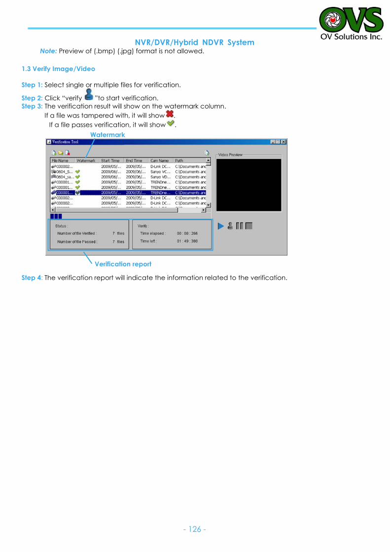
NVR/DVR/Hybrid NDVR System
- 126 -
Watermark
Verification report
Note: Preview of (.bmp) (.jpg) format is not allowed.
1.3 Verify Image/Video
Step 1: Select single or multiple files for verification.
Step 2: Click “verify ”to start verification.
Step 3: The verification result will show on the watermark column.
If a file was tampered with, it will show .
If a file passes verification, it will show .
Step 4: The verification report will indicate the information related to the verification.
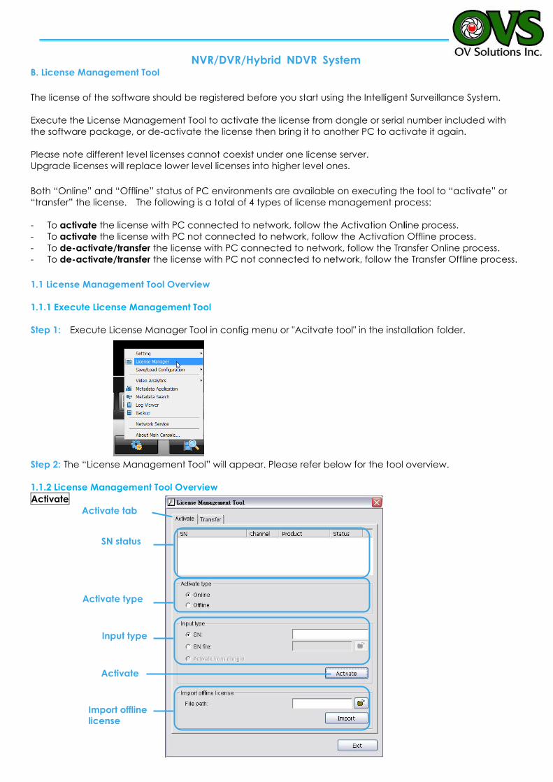
NVR/DVR/Hybrid NDVR System
- 127 -
B. License Management Tool
The license of the software should be registered before you start using the Intelligent Surveillance System.
Execute the License Management Tool to activate the license from dongle or serial number included with
the software package, or de-activate the license then bring it to another PC to activate it again.
Please note different level licenses cannot coexist under one license server.
Upgrade licenses will replace lower level licenses into higher level ones.
Both “Online” and “Offline” status of PC environments are available on executing the tool to “activate” or
“transfer” the license. The following is a total of 4 types of license management process:
- To activate the license with PC connected to network, follow the Activation Online process.
- To activate the license with PC not connected to network, follow the Activation Offline process.
- To de-activate/transfer the license with PC connected to network, follow the Transfer Online process.
- To de-activate/transfer the license with PC not connected to network, follow the Transfer Offline process.
1.1 License Management Tool Overview
1.1.1 Execute License Management Tool
Step 1: Execute License Manager Tool in config menu or "Acitvate tool" in the installation folder.
Step 2: The “License Management Tool” will appear. Please refer below for the tool overview.
1.1.2 License Management Tool Overview
Activate
Activate
Activate type
Activate tab
SN status
Input type
Import offline license
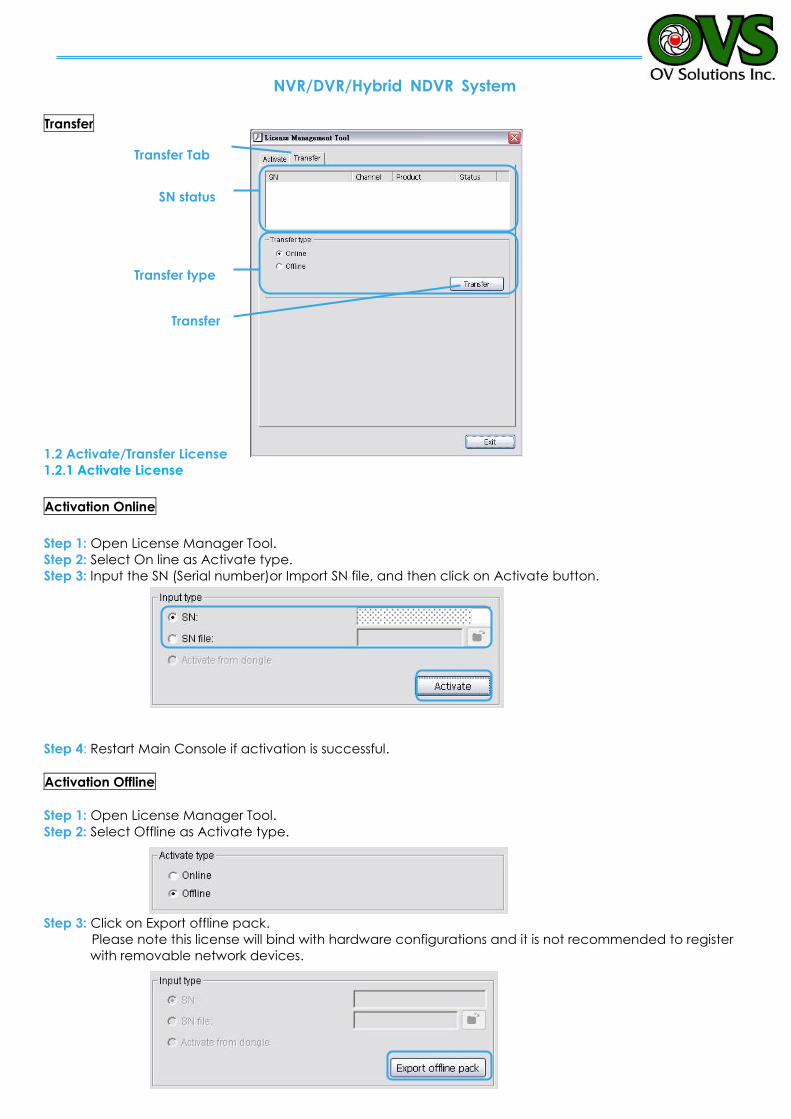
NVR/DVR/Hybrid NDVR System
- 128 -
Transfer
1.2 Activate/Transfer License
1.2.1 Activate License
Activation Online
Step 1: Open License Manager Tool.
Step 2: Select On line as Activate type.
Step 3: Input the SN (Serial number)or Import SN file, and then click on Activate button.
Step 4: Restart Main Console if activation is successful.
Activation Offline
Step 1: Open License Manager Tool.
Step 2: Select Offline as Activate type.
Step 3: Click on Export offline pack.
Please note this license will bind with hardware configurations and it is not recommended to register
with removable network devices.
Transfer
Transfer type
SN status
Transfer Tab
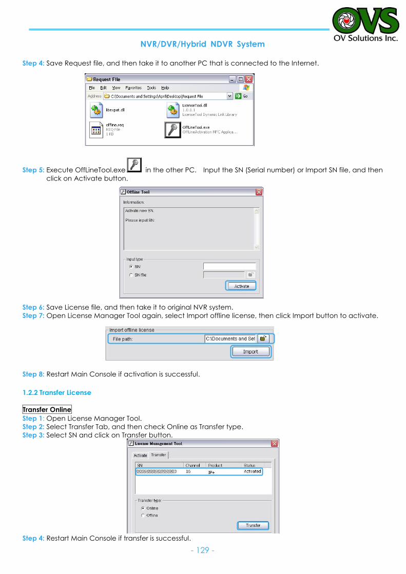
NVR/DVR/Hybrid NDVR System
- 129 -
Step 4: Save Request file, and then take it to another PC that is connected to the Internet.
Step 5: Execute OffLineTool.exe in the other PC. Input the SN (Serial number) or Import SN file, and then
click on Activate button.
Step 6: Save License file, and then take it to original NVR system.
Step 7: Open License Manager Tool again, select Import offline license, then click Import button to activate.
Step 8: Restart Main Console if activation is successful.
1.2.2 Transfer License
Transfer Online
Step 1: Open License Manager Tool.
Step 2: Select Transfer Tab, and then check Online as Transfer type.
Step 3: Select SN and click on Transfer button.
Step 4: Restart Main Console if transfer is successful.
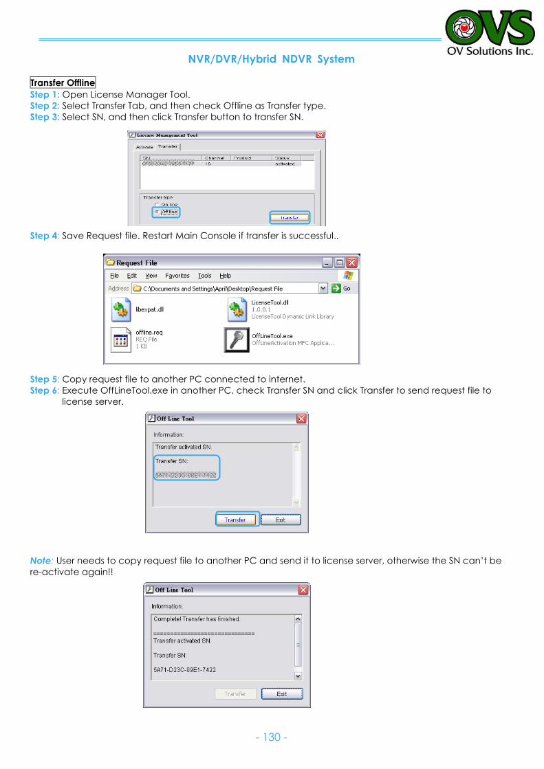
NVR/DVR/Hybrid NDVR System
- 130 -
Transfer Offline
Step 1: Open License Manager Tool.
Step 2: Select Transfer Tab, and then check Offline as Transfer type.
Step 3: Select SN, and then click Transfer button to transfer SN.
Step 4: Save Request file. Restart Main Console if transfer is successful..
Step 5: Copy request file to another PC connected to internet.
Step 6: Execute OffLineTool.exe in another PC, check Transfer SN and click Transfer to send request file to
license server.
Note: User needs to copy request file to another PC and send it to license server, otherwise the SN can’t be
re-activate again!!
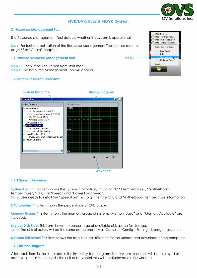
NVR/DVR/Hybrid NDVR System
- 131 -
C. Resource Management Tool
The Resource Management Tool detects whether the system is operational.
Note: For further application of the Resource Management Tool, please refer to
page 58 In “Guard” chapter.
1.1 Execute Resource Management tool
Step 1: Open Resource Report from start menu.
Step 2: The Resource Management Tool will appear.
1.2 System Resource Overview
1.2.1 System Resource
System Health: This item shows the system information, including “CPU Temperature”, “Motherboard
Temperature”, “CPU Fan Speed” and “Power Fan Speed”.
Note: User needs to install the “SpeedFan” first to gather the CPU and Motherboard temperature information.
CPU Loading: This item shows the percentage of CPU usage.
Memory Usage: This item shows the memory usage of system. “Memory Used” and “Memory Available” are
included.
Logical Disk Free: This item shows the percentage of available disk space for storage.
Note: The disk directory will be the same as the one in MainConsole – Config – Setting – Storage - Location.
Network Utilization: This item shows the total bit-rate utilization for the upload and download of the computer.
1.2.2 Instant Diagram
Click each item in the list to obtain the instant system diagram. The “system resource” will be displayed as
each variable in Vertical Axis; the unit of Horizontal Axis will be displayed as “Per Second”.
Step 1
Advance
d
History Diagram System Resource
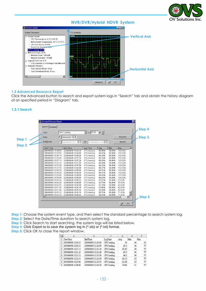
NVR/DVR/Hybrid NDVR System
- 132 -
1.3 Advanced Resource Report
Click the Advanced button to search and export system logs in “Search” tab and obtain the history diagram
of an specified period in “Diagram” tab.
1.3.1 Search
Step 1: Choose the system event type, and then select the standard percentage to search system log.
Step 2: Select the Date/Time duration to search system log.
Step 3: Click Search to start searching, the system logs will be listed below. Step 4: Click Export to to save the system log in (*.xls) or (*.txt) format.
Step 5: Click OK to close the report window.
Horizontal Axis
Vertical Axis
Step 1
Step 2
Step 4
Step 3
Step 5
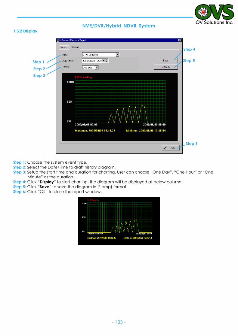
NVR/DVR/Hybrid NDVR System
- 133 -
1.3.2 Display
Step 1: Choose the system event type.
Step 2: Select the Date/Time to draft history diagram.
Step 3: Setup the start time and duration for charting. User can choose “One Day”, “One Hour” or “One
Minute” as the duration.
Step 4: Click “Display” to start charting, the diagram will be displayed at below column.
Step 5: Click “Save” to save the diagram in (*.bmp) format.
Step 6: Click “OK” to close the report window.
Step 6
Step 4
Step 5 Step 1
Step 2
Step 3
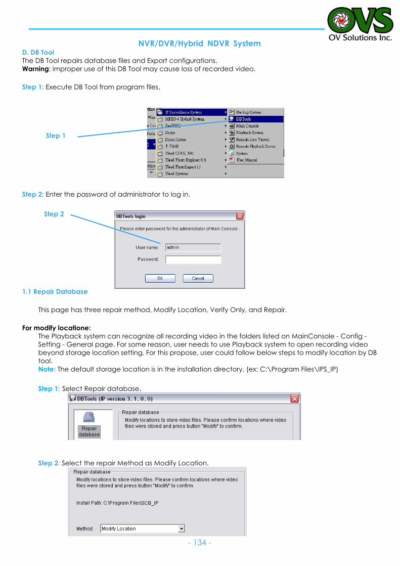
NVR/DVR/Hybrid NDVR System
- 134 -
D. DB Tool
The DB Tool repairs database files and Export configurations.
Warning: improper use of this DB Tool may cause loss of recorded video.
Step 1: Execute DB Tool from program files.
Step 2: Enter the password of administrator to log in.
1.1 Repair Database
This page has three repair method, Modify Location, Verify Only, and Repair.
For modify locatione:
The Playback system can recognize all recording video in the folders listed on MainConsole - Config -
Setting - General page. For some reason, user needs to use Playback system to open recording video
beyond storage location setting. For this propose, user could follow below steps to modify location by DB
tool.
Note: The default storage location is in the installation directory, (ex: C:\Program Files\IPS_IP)
Step 1: Select Repair database.
Step 2: Select the repair Method as Modify Location.
Step 2
Step 1
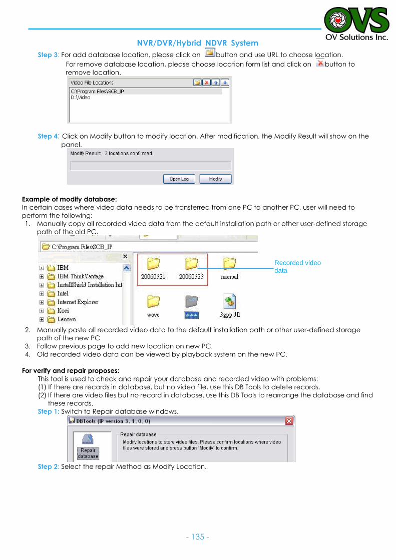
NVR/DVR/Hybrid NDVR System
- 135 -
Step 3: For add database location, please click on button and use URL to choose location.
For remove database location, please choose location form list and click on button to
remove location.
Step 4: Click on Modify button to modify location. After modification, the Modify Result will show on the
panel.
Example of modify database:
In certain cases where video data needs to be transferred from one PC to another PC, user will need to
perform the following:
1. Manually copy all recorded video data from the default installation path or other user-defined storage
path of the old PC.
2. Manually paste all recorded video data to the default installation path or other user-defined storage
path of the new PC
3. Follow previous page to add new location on new PC.
4. Old recorded video data can be viewed by playback system on the new PC.
For verify and repair proposes:
This tool is used to check and repair your database and recorded video with problems:
(1) If there are records in database, but no video file, use this DB Tools to delete records.
(2) If there are video files but no record in database, use this DB Tools to rearrange the database and find
these records.
Step 1: Switch to Repair database windows.
Step 2: Select the repair Method as Modify Location.
Recorded video data
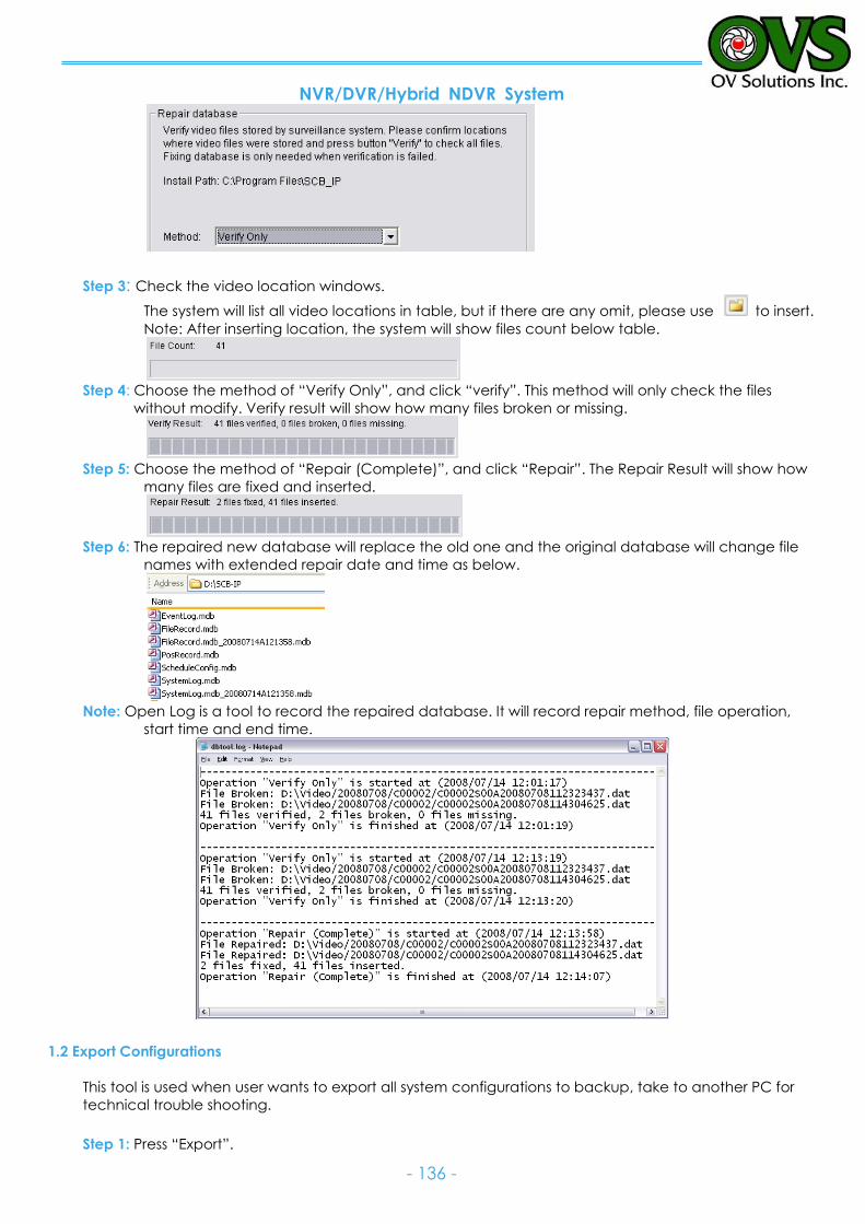
NVR/DVR/Hybrid NDVR System
- 136 -
Step 3: Check the video location windows.
The system will list all video locations in table, but if there are any omit, please use to insert.
Note: After inserting location, the system will show files count below table.
Step 4: Choose the method of “Verify Only”, and click “verify”. This method will only check the files
without modify. Verify result will show how many files broken or missing.
Step 5: Choose the method of “Repair (Complete)”, and click “Repair”. The Repair Result will show how
many files are fixed and inserted.
Step 6: The repaired new database will replace the old one and the original database will change file
names with extended repair date and time as below.
Note: Open Log is a tool to record the repaired database. It will record repair method, file operation,
start time and end time.
1.2 Export Configurations
This tool is used when user wants to export all system configurations to backup, take to another PC for
technical trouble shooting.
Step 1: Press “Export”.
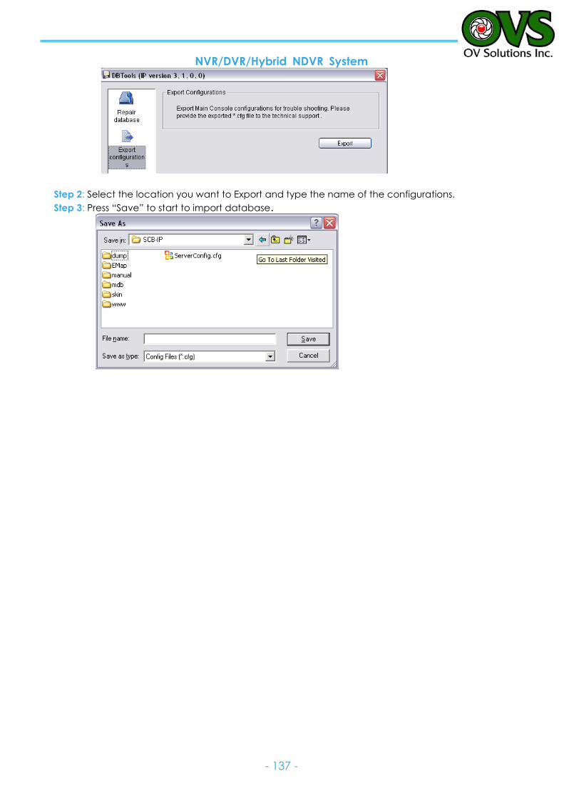
NVR/DVR/Hybrid NDVR System
- 137 -
Step 2: Select the location you want to Export and type the name of the configurations.
Step 3: Press “Save” to start to import database.
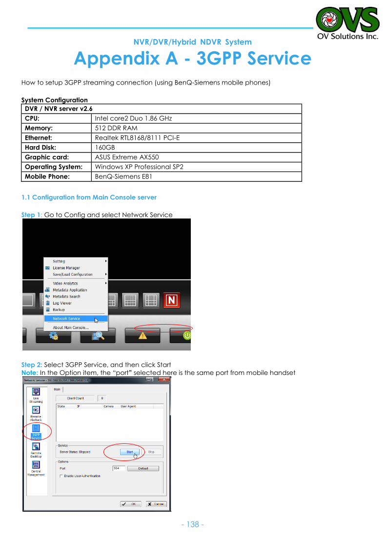
NVR/DVR/Hybrid NDVR System
- 138 -
Appendix A - 3GPP Service How to setup 3GPP streaming connection (using BenQ-Siemens mobile phones)
System Configuration
DVR / NVR server v2.6
CPU: Intel core2 Duo 1.86 GHz
Memory: 512 DDR RAM
Ethernet: Realtek RTL8168/8111 PCI-E
Hard Disk: 160GB
Graphic card: ASUS Extreme AX550
Operating System: Windows XP Professional SP2
Mobile Phone: BenQ-Siemens E81
1.1 Configuration from Main Console server
Step 1: Go to Config and select Network Service
Step 2: Select 3GPP Service, and then click Start
Note: In the Option item, the “port” selected here is the same port from mobile handset
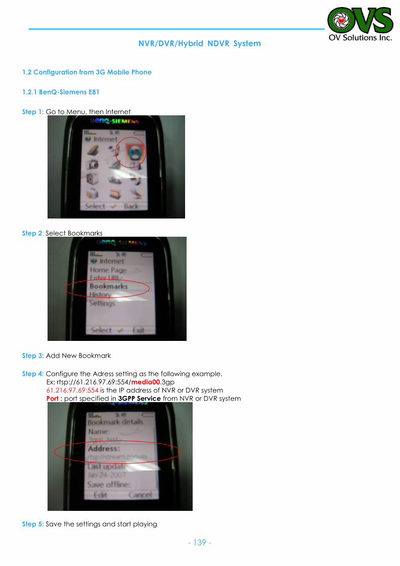
NVR/DVR/Hybrid NDVR System
- 139 -
1.2 Configuration from 3G Mobile Phone
1.2.1 BenQ-Siemens E81
Step 1: Go to Menu, then Internet
Step 2: Select Bookmarks
Step 3: Add New Bookmark
Step 4: Configure the Adress setting as the following example.
Ex: rtsp://61.216.97.69:554/media00.3gp
61.216.97.69:554 is the IP address of NVR or DVR system
Port : port specified in 3GPP Service from NVR or DVR system
Step 5: Save the settings and start playing
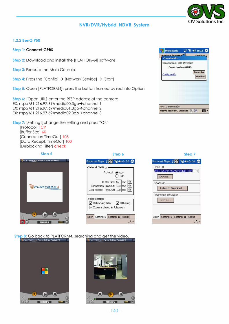
NVR/DVR/Hybrid NDVR System
- 140 -
1.2.2 BenQ P50
Step 1: Connect GPRS Step 2: Download and install the [PLATFORM4] software.
Step 3: Execute the Main Console.
Step 4: Press the [Config] [Network Service] [Start]
Step 5: Open [PLATFORM4], press the button framed by red into Option
Step 6: [Open URL] enter the RTSP address of the camera
EX: rtsp://61.216.97.69/media00.3gpchannel 1
EX: rtsp://61.216.97.69/media01.3gpchannel 2
EX: rtsp://61.216.97.69/media02.3gpchannel 3
Step 7: [Setting I]change the setting and press “OK”
[Protocol] TCP
[Buffer Size] 60
[Connection TimeOut] 103
[Data Recept. TimeOut] 100
[Deblocking Filter] check
Step 8: Go back to PLATFORM4, searching and get the video.
Step 5 Step 6 Step 7

NVR/DVR/Hybrid NDVR System
- 141 -
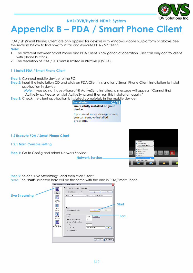
NVR/DVR/Hybrid NDVR System
- 142 -
Appendix B – PDA / Smart Phone Client PDA / SP (Smart Phone) Client are only applied for devices with Windows Mobile 5.0 platform or above. See
the sections below to find how to install and execute PDA / SP Client.
Note:
1. The different between Smart Phone and PDA Client is navigation of operation, user can only control client
with phone buttons.
2. The resolution of PDA / SP Client is limited in 240*320 (QVGA).
1.1 Install PDA / Smart Phone Client
Step 1: Connect mobile device to the PC.
Step 2: Insert the installation CD and click on PDA Client Installation / Smart Phone Client Installation to install
application in device.
Note: If you do not have Microsoft® ActiveSync installed, a message will appear “Cannot find
ActiveSync. Please reinstall ActiveSync and then run this installation again.”
Step 3: Check the client application is installed completely in the mobile device.
1.2 Execute PDA / Smart Phone Client
1.2.1 Main Console setting
Step 1: Go to Config and select Network Service
Step 2: Select “Live Streaming”, and then click “Start”.
Note: The “Port” selected here will be the same with the one in PDA/Smart Phone.
Live Streaming
Start
Port
Network Service
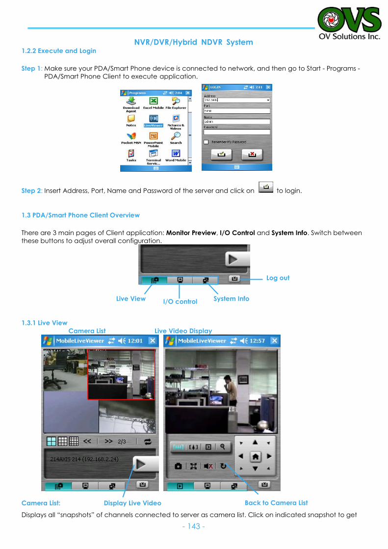
NVR/DVR/Hybrid NDVR System
- 143 -
1.2.2 Execute and Login
Step 1: Make sure your PDA/Smart Phone device is connected to network, and then go to Start - Programs -
PDA/Smart Phone Client to execute application.
Step 2: Insert Address, Port, Name and Password of the server and click on to login.
1.3 PDA/Smart Phone Client Overview
There are 3 main pages of Client application: Monitor Preview, I/O Control and System Info. Switch between
these buttons to adjust overall configuration.
1.3.1 Live View
Camera List Live Video Display
Camera List:
Displays all “snapshots” of channels connected to server as camera list. Click on indicated snapshot to get
Back to Camera List
Display Live Video
Log out
I/O control Live View System Info
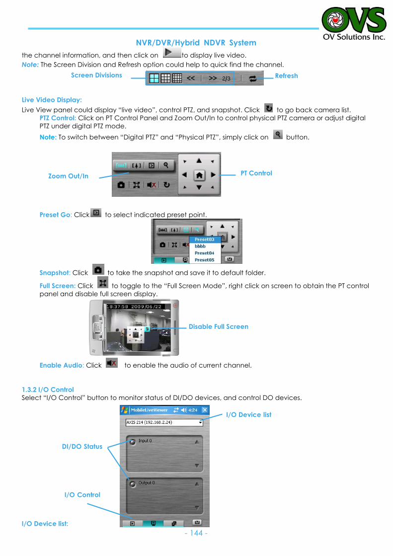
NVR/DVR/Hybrid NDVR System
- 144 -
the channel information, and then click on to display live video.
Note: The Screen Division and Refresh option could help to quick find the channel.
Live Video Display:
Live View panel could display “live video”, control PTZ, and snapshot. Click to go back camera list.
PTZ Control: Click on PT Control Panel and Zoom Out/In to control physical PTZ camera or adjust digital
PTZ under digital PTZ mode.
Note: To switch between “Digital PTZ” and “Physical PTZ”, simply click on button.
Preset Go: Click to select indicated preset point.
Snapshot: Click to take the snapshot and save it to default folder.
Full Screen: Click to toggle to the “Full Screen Mode”, right click on screen to obtain the PT control
panel and disable full screen display.
Enable Audio: Click to enable the audio of current channel.
1.3.2 I/O Control
Select “I/O Control” button to monitor status of DI/DO devices, and control DO devices.
I/O Device list:
Disable Full Screen
PT Control Zoom Out/In
Refresh Screen Divisions
DI/DO Status
I/O Control
I/O Device list
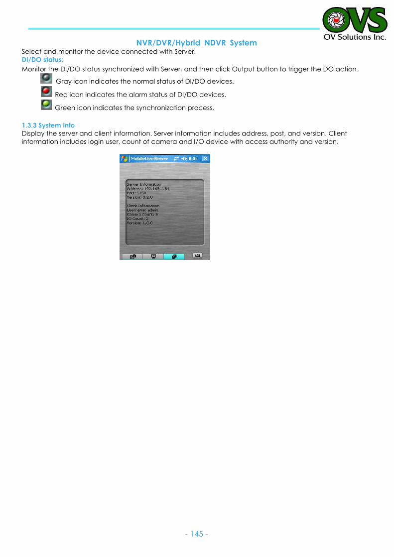
NVR/DVR/Hybrid NDVR System
- 145 -
Select and monitor the device connected with Server.
DI/DO status:
Monitor the DI/DO status synchronized with Server, and then click Output button to trigger the DO action.
Gray icon indicates the normal status of DI/DO devices.
Red icon indicates the alarm status of DI/DO devices.
Green icon indicates the synchronization process.
1.3.3 System Info
Display the server and client information. Server information includes address, post, and version. Client
information includes login user, count of camera and I/O device with access authority and version.
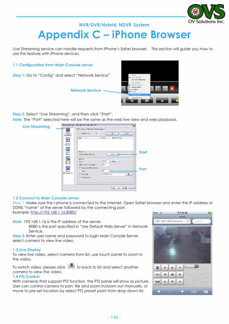
NVR/DVR/Hybrid NDVR System
- 146 -
Appendix C – iPhone Browser Live Streaming service can handle requests from iPhone’s Safari browser. This section will guide you how to
use this feature with iPhone devices.
1.1 Configuration from Main Console server
Step 1: Go to “Config” and select “Network Service”
Step 2: Select “Live Streaming”, and then click “Start”.
Note: The “Port” selected here will be the same as the web live view and web playback.
1.2 Connect to Main Console server
Step 1: Make sure the I-phone is connected to the internet. Open Safari browser and enter the IP address or
DDNS “name” of the server followed by the connecting port.
Example: http://192.168.1.16:8080/
Note: 192.168.1.16 is the IP address of the server.
8080 is the port specified in “Use Default Web Server” in Network
Service.
Step 2: Enter user name and password to login Main Console Server,
select camera to view live video.
1.3 Live Display
To view live video, select camera from list, use touch panel to zoom in
the video.
To switch video, please click to back to list and select another
camera to view the video.
1.4 PTZ Control
With cameras that support PTZ function, the PTZ panel will show as picture.
User can control camera to pan, tile and zoom in/zoom out manually, or
move to pre-set location by select PTZ preset point from drop down list.
Network Service
Live Streaming
Start
Port
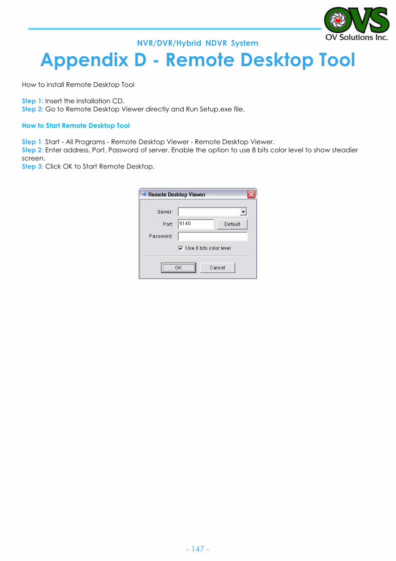
NVR/DVR/Hybrid NDVR System
- 147 -
Appendix D - Remote Desktop Tool How to install Remote Desktop Tool
Step 1: Insert the Installation CD.
Step 2: Go to Remote Desktop Viewer directly and Run Setup.exe file.
How to Start Remote Desktop Tool
Step 1: Start - All Programs - Remote Desktop Viewer - Remote Desktop Viewer.
Step 2: Enter address, Port, Password of server. Enable the option to use 8 bits color level to show steadier
screen.
Step 3: Click OK to Start Remote Desktop.