nvidia bit display ptrs (‘u’), bit dp ptrs...
TRANSCRIPT
NVIDIA BIT_DISPLAY_PTRS (‘U’), BIT_DP_PTRS ('d')
Contents BIT_DISPLAY_PTRS (‘U’) ................................................................................................................................ 1
Display Script Table ................................................................................................................................... 1
Display Control Flag Byte ...................................................................................................................... 8
BIT_DP_PTRS ('d') .......................................................................................................................................... 8
DP Info Table ............................................................................................................................................. 8
DP Info Table Header ............................................................................................................................ 9
DP Info Table Entries ........................................................................................................................... 11
DP Info Level Entry Table .................................................................................................................... 11
DP Info Table Target Entry .................................................................................................................. 13
BIT_DISPLAY_PTRS (‘U’)
Display Script Table
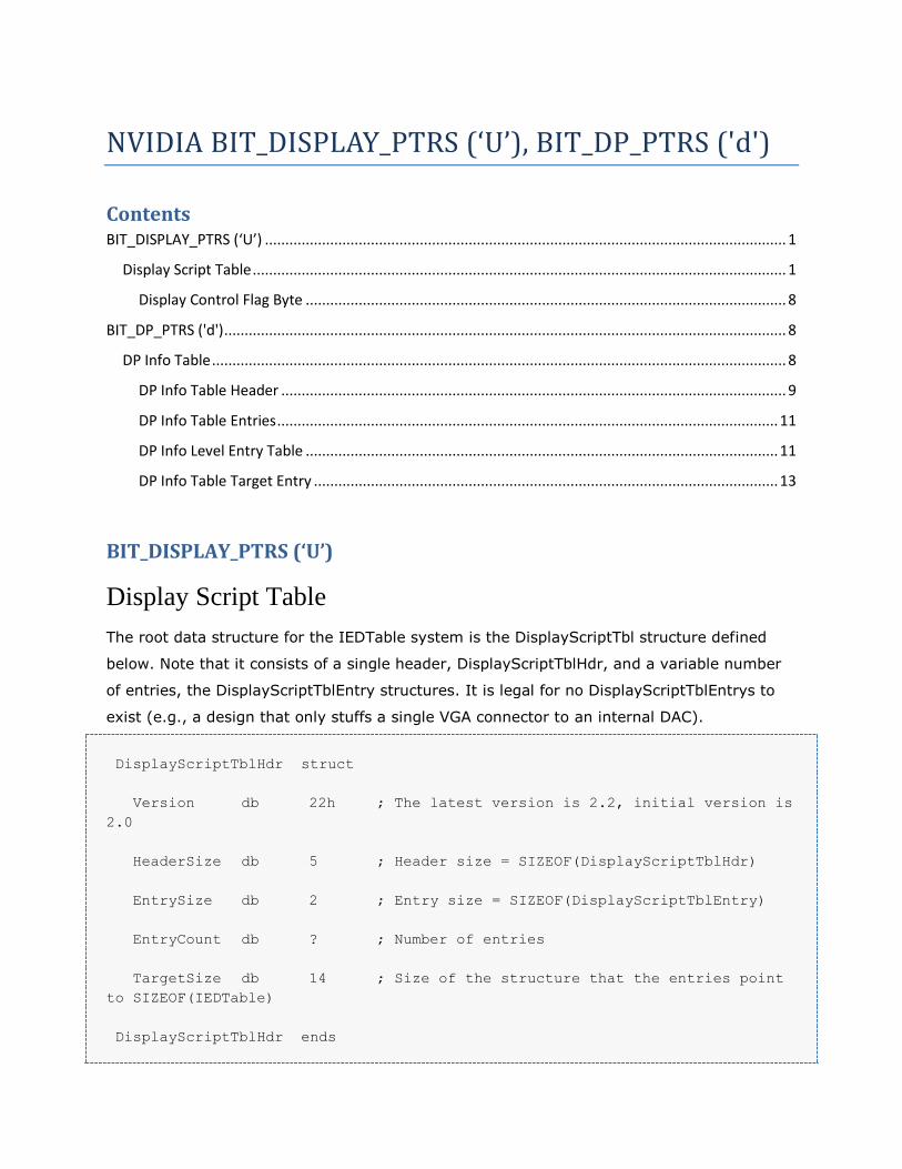
The root data structure for the IEDTable system is the DisplayScriptTbl structure defined
below. Note that it consists of a single header, DisplayScriptTblHdr, and a variable number
of entries, the DisplayScriptTblEntry structures. It is legal for no DisplayScriptTblEntrys to
exist (e.g., a design that only stuffs a single VGA connector to an internal DAC).
DisplayScriptTblHdr struct
Version db 22h ; The latest version is 2.2, initial version is
2.0
HeaderSize db 5 ; Header size = SIZEOF(DisplayScriptTblHdr)
EntrySize db 2 ; Entry size = SIZEOF(DisplayScriptTblEntry)
EntryCount db ? ; Number of entries
TargetSize db 14 ; Size of the structure that the entries point
to SIZEOF(IEDTable)
DisplayScriptTblHdr ends
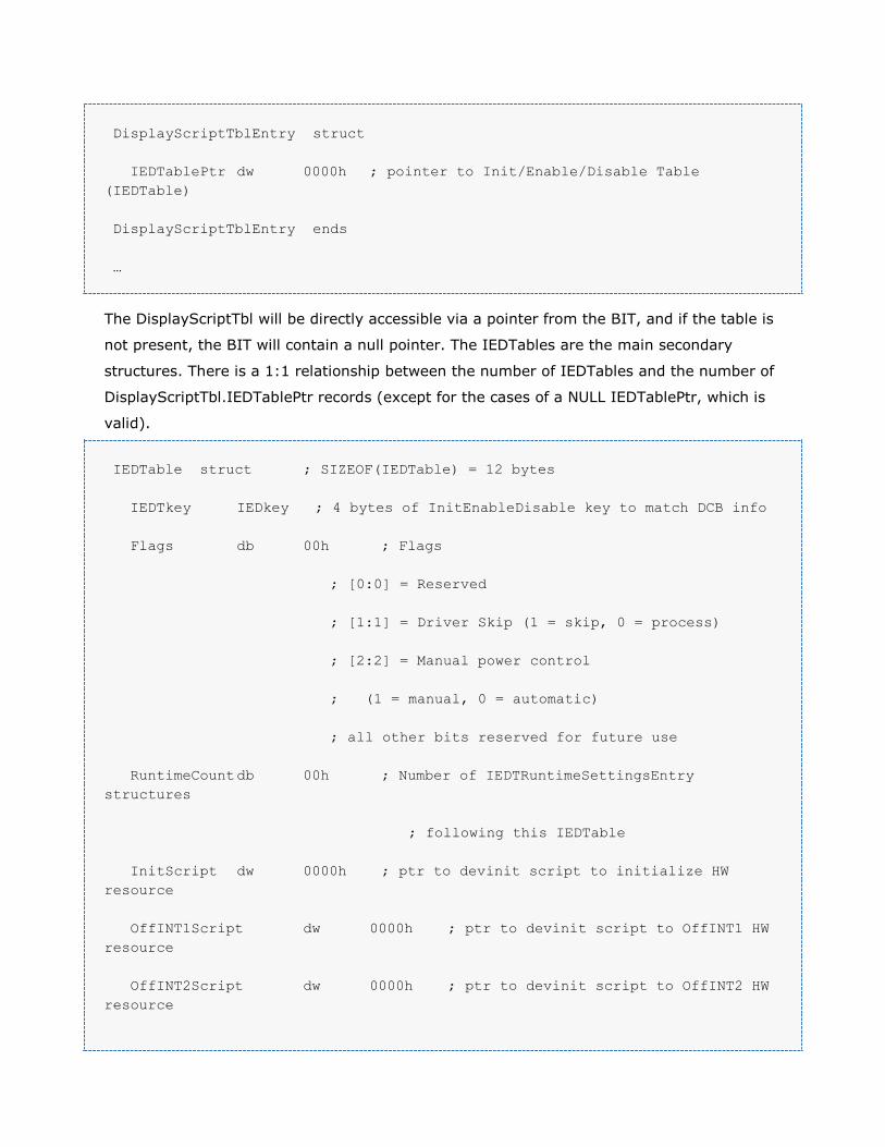
DisplayScriptTblEntry struct
IEDTablePtr dw 0000h ; pointer to Init/Enable/Disable Table
(IEDTable)
DisplayScriptTblEntry ends
…
The DisplayScriptTbl will be directly accessible via a pointer from the BIT, and if the table is
not present, the BIT will contain a null pointer. The IEDTables are the main secondary
structures. There is a 1:1 relationship between the number of IEDTables and the number of
DisplayScriptTbl.IEDTablePtr records (except for the cases of a NULL IEDTablePtr, which is
valid).
IEDTable struct ; SIZEOF(IEDTable) = 12 bytes
IEDTkey IEDkey ; 4 bytes of InitEnableDisable key to match DCB info
Flags db 00h ; Flags
; [0:0] = Reserved
; [1:1] = Driver Skip (1 = skip, 0 = process)
; [2:2] = Manual power control
; (1 = manual, 0 = automatic)
; all other bits reserved for future use
RuntimeCount db 00h ; Number of IEDTRuntimeSettingsEntry
structures
; following this IEDTable
InitScript dw 0000h ; ptr to devinit script to initialize HW
resource
OffINT1Script dw 0000h ; ptr to devinit script to OffINT1 HW
resource
OffINT2Script dw 0000h ; ptr to devinit script to OffINT2 HW
resource

IEDTable ends
IEDTRuntimeSettingsEntry STRUCT
Protocol db 00h ; Output Resource Protocol for this entry
DeviceFlags db 00h ; Device specific flags
;(dlink/slink, 18/24 bpp, etc.) for this
entry
OnINT2Table dw 0000h ; Pointer to SorClkMode array for scripts to
run
; during supervisior interrupt 2
OnINT3Table dw 0000h ; Pointer to SorClkMode array for scripts to
run
; during supervisior interrupt 3
IEDTRuntimeSettingsEntry ENDS
…
The IEDTkey is used to match against a particular DCB record. To this end, the alignment of
the relevant bit fields in the IEDTkey were chosen to exactly match up to the bit fields in the
DCB 3.0 specification. The algorithm for matching an IEDTkey to a DCB is described below.
A match is made when the followings are all true:
1. The IEDTkeyDCBDPI.Type, Location, and IEDTkeyDCBDSI.SubType bit fields match
all of the equivalent DCB bit fields—i.e., all bit field 1’s and 0’s are identical.
2. The IEDTkeyDCBDPI.Head bits which are set to 1 correspond to the head (display
pipe) the device is attached to --i.e., (IEDTkeyDCBDPI.Head & CurrentHead) != 0.
3. All of the IEDTkeyDCBDPI.Outdev bits which are set to 1 correspond to any of the
DCB.OutDev bits which are set to 1—i.e., (IEDTkeyDCBDPI.Outdev &
DCB.Outdev) != 0.
4. For version 2.1, all of the IEDTkeyDCBDPI.Sublink bits which are set to 1 correspond
to any of the DCB.Sublink bits which are set to 1-i.e. (IEDTkeyDCBDPI.Sublink &
DCB.Sublink) != 0.
For IED 2.0, this is the IEDKey:
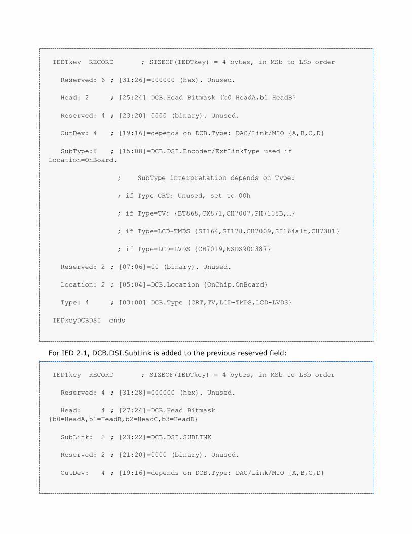
IEDTkey RECORD ; SIZEOF(IEDTkey) = 4 bytes, in MSb to LSb order
Reserved: 6 ; [31:26]=000000 (hex). Unused.
Head: 2 ; [25:24]=DCB.Head Bitmask {b0=HeadA,b1=HeadB}
Reserved: 4 ; [23:20]=0000 (binary). Unused.
OutDev: 4 ; [19:16]=depends on DCB.Type: DAC/Link/MIO {A,B,C,D}
SubType:8 ; [15:08]=DCB.DSI.Encoder/ExtLinkType used if
Location=OnBoard.
; SubType interpretation depends on Type:
; if Type=CRT: Unused, set to=00h
; if Type=TV: {BT868,CX871,CH7007,PH7108B,…}
; if Type=LCD-TMDS {SI164,SI178,CH7009,SI164alt,CH7301}
; if Type=LCD=LVDS {CH7019,NSDS90C387}
Reserved: 2 ; [07:06]=00 (binary). Unused.
Location: 2 ; [05:04]=DCB.Location {OnChip,OnBoard}
Type: 4 ; [03:00]=DCB.Type {CRT,TV,LCD-TMDS,LCD-LVDS}
IEDkeyDCBDSI ends
For IED 2.1, DCB.DSI.SubLink is added to the previous reserved field:
IEDTkey RECORD ; SIZEOF(IEDTkey) = 4 bytes, in MSb to LSb order
Reserved: 4 ; [31:28]=000000 (hex). Unused.
Head: 4 ; [27:24]=DCB.Head Bitmask
{b0=HeadA,b1=HeadB,b2=HeadC,b3=HeadD}
SubLink: 2 ; [23:22]=DCB.DSI.SUBLINK
Reserved: 2 ; [21:20]=0000 (binary). Unused.
OutDev: 4 ; [19:16]=depends on DCB.Type: DAC/Link/MIO {A,B,C,D}
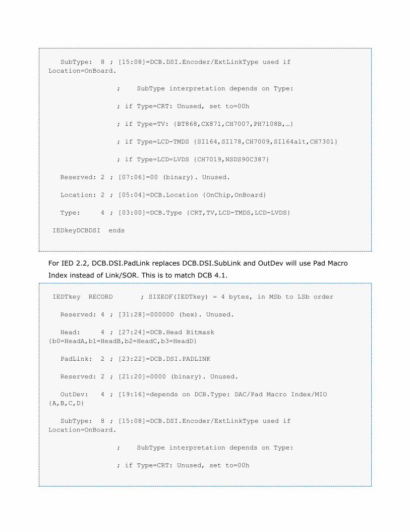
SubType: 8 ; [15:08]=DCB.DSI.Encoder/ExtLinkType used if
Location=OnBoard.
; SubType interpretation depends on Type:
; if Type=CRT: Unused, set to=00h
; if Type=TV: {BT868,CX871,CH7007,PH7108B,…}
; if Type=LCD-TMDS {SI164,SI178,CH7009,SI164alt,CH7301}
; if Type=LCD=LVDS {CH7019,NSDS90C387}
Reserved: 2 ; [07:06]=00 (binary). Unused.
Location: 2 ; [05:04]=DCB.Location {OnChip,OnBoard}
Type: 4 ; [03:00]=DCB.Type {CRT,TV,LCD-TMDS,LCD-LVDS}
IEDkeyDCBDSI ends
For IED 2.2, DCB.DSI.PadLink replaces DCB.DSI.SubLink and OutDev will use Pad Macro
Index instead of Link/SOR. This is to match DCB 4.1.
IEDTkey RECORD ; SIZEOF(IEDTkey) = 4 bytes, in MSb to LSb order
Reserved: 4 ; [31:28]=000000 (hex). Unused.
Head: 4 ; [27:24]=DCB.Head Bitmask
{b0=HeadA,b1=HeadB,b2=HeadC,b3=HeadD}
PadLink: 2 ; [23:22]=DCB.DSI.PADLINK
Reserved: 2 ; [21:20]=0000 (binary). Unused.
OutDev: 4 ; [19:16]=depends on DCB.Type: DAC/Pad Macro Index/MIO
{A,B,C,D}
SubType: 8 ; [15:08]=DCB.DSI.Encoder/ExtLinkType used if
Location=OnBoard.
; SubType interpretation depends on Type:
; if Type=CRT: Unused, set to=00h

; if Type=TV: {BT868,CX871,CH7007,PH7108B,…}
; if Type=LCD-TMDS {SI164,SI178,CH7009,SI164alt,CH7301}
; if Type=LCD=LVDS {CH7019,NSDS90C387}
Reserved: 2 ; [07:06]=00 (binary). Unused.
Location: 2 ; [05:04]=DCB.Location {OnChip,OnBoard}
Type: 4 ; [03:00]=DCB.Type {CRT,TV,LCD-TMDS,LCD-LVDS}
IEDkeyDCBDSI ends
The flag at IEDTable.Flags.1 is used to signal to the Resource Manager that it should not
process the entry for that device. The Resource Manager should instead either not utilize
the device or use any hard coded initialization it has available. This allows entries to be
added for the use by the VBIOS that are either not tested yet with the Resource Manager or
that are not appropriate for use by the Resource Manager for other reasons.
The flag at IEDTable.Flags 2 is used to signal that a device requires “manual” power control.
These are usually PIOR devices that require a running pixel clock when communicating with
the device via the I2C protocol. See the Device Control Specification for more information.
The InitScript field points to a devinit script to run at boot time. At boot, the software
performing the GPU initialization (VBIOS, resman, fcode, etc.) loops through each DCB
entry present in the firmware image and looks for a matching IEDT entry. For each one it
locates, the software must execute the InitScript for that entry. If the InitScript field is
NULL, execution of the script is skipped.
The OffINT1Script field points to a script that must be run during Supervisior Interrupt 1
for a matching device if the device was previously running before the display update (mode
set) and is now being shutdown, either because the device is being disabled or because of a
change in backend timings or pixel clock. If the OffINT1Script field is NULL, execution of the
script is skipped.
The RuntimeCount field is a count of how many IEDTRuntimeSettingsEntry structures are
immediately following this IEDTable structure. Each IEDTRuntimeSettingsEntry structure
represents a possible runtime configuration of the matching device. It is possible for some
runtime configurations to not have any matching entries. It is also possible for
RuntimeCount to be zero for a device that only has an InitScript and/or OffINT1Script.
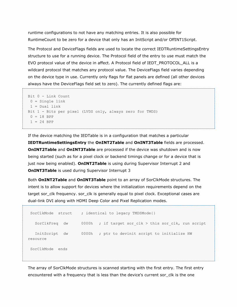
The Protocol and DeviceFlags fields are used to locate the correct IEDTRuntimeSettingsEntry
structure to use for a running device. The Protocol field of the entry to use must match the
EVO protocol value of the device in affect. A Protocol field of IEDT_PROTOCOL_ALL is a
wildcard protocol that matches any protocol value. The DeviceFlags field varies depending
on the device type in use. Currently only flags for flat panels are defined (all other devices
always have the DeviceFlags field set to zero). The currently defined flags are:
Bit 0 - Link Count
0 = Single link
1 = Dual link
Bit 1 - Bits per pixel (LVDS only, always zero for TMDS)
0 = 18 BPP
1 = 24 BPP
If the device matching the IEDTable is in a configuration that matches a particular
IEDTRuntimeSettingsEntry the OnINT2Table and OnINT3Table fields are processed.
OnINT2Table and OnINT3Table are processed if the device was shutdown and is now
being started (such as for a pixel clock or backend timings change or for a device that is
just now being enabled). OnINT2Table is using during Supervisor Interrupt 2 and
OnINT3Table is used during Supervisor Interrupt 3
Both OnINT2Table and OnINT3Table point to an array of SorClkMode structures. The
intent is to allow support for devices where the initialization requirements depend on the
target sor_clk frequency. sor_clk is generally equal to pixel clock. Exceptional cases are
dual-link DVI along with HDMI Deep Color and Pixel Replication modes.
SorClkMode struct ; identical to legacy TMDSMode{}
SorClkFreq dw 0000h ; if target sor_clk > this sor_clk, run script
InitScript dw 0000h ; ptr to devinit script to initialize HW
resource
SorClkMode ends
The array of SorClkMode structures is scanned starting with the first entry. The first entry
encountered with a frequency that is less than the device's current sor_clk is the one

chosen. The SorClkFreq field value is specified in 10 kHz units. The devinit script pointed to
by the InitScript field of the chosen entry is executed. The last entry in an array of
SorClkMode structures will always have a frequency of 0 kHz so that a valid entry is always
found.
Is it is valid for either OnINT2Table or OnINT3Table to be NULL pointers, in which case
script execution is skipped for that period. Also, it is valid for any of the script pointers in
the array of SorClkMode structures to be NULL, in which case script execution is skipped as
well.
For a device that does not have scripts that are a function of frequency there will be only
one SorClkMode structure with the SorClkMode.SorClkFreq field specified as 0 kHz.
Display Control Flag Byte
[0:0] = Reserved
[1:1] = NO_DISPLAY_SUBSYSTEM: Display subsystem isn't included in the GPU
(used for displayless coproc) [2:2] = Reserved
[3:3] = VBIOS avoids touching mempool while drivers running
[4:4] = Offset PCLK between 2 heads
[5:5] = Boot with DP Hotplug disabled
[6:6] = Allow detection of DP sinks by doing a DPCD register read [7:7] = Reserved
BIT_DP_PTRS ('d')
BIT_DP_PTRS ('d') - DP Info Table contains tables and scripts to enable the support of
various DP functionality. DP Info Table can be referenced through BIT_TOKEN_DP_PTRS('d') in BIT table.
DP Info Table
DP Info Table consists of the following parts:
Header - The version number (0x4x for Version 4.x), header size, the size of each DP
Info Table Entry, the number of Entries, size of the structures that the entries point to,
size of each level entry, and a flag byte.
DP Info Table entries list - One for each DP link. Each entry consists a pointer which
points to the corresponding Target Entry(DPInfoStruct).
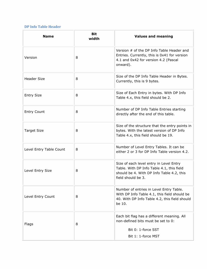
DP Info Table Header
Name Bit
width Values and meaning
Version 8
Version # of the DP Info Table Header and
Entries. Currently, this is 0x41 for version
4.1 and 0x42 for version 4.2 (Pascal
onward).
Header Size 8 Size of the DP Info Table Header in Bytes.
Currently, this is 9 bytes.
Entry Size 8 Size of Each Entry in bytes. With DP Info
Table 4.x, this field should be 2.
Entry Count 8 Number of DP Info Table Entries starting
directly after the end of this table.
Target Size 8
Size of the structure that the entry points in
bytes. With the latest version of DP Info
Table 4.x, this field should be 19.
Level Entry Table Count 8 Number of Level Entry Tables. It can be
either 2 or 3 for DP Info Table version 4.2.
Level Entry Size 8
Size of each level entry in Level Entry
Table. With DP Info Table 4.1, this field
should be 4. With DP Info Table 4.2, this
field should be 3.
Level Entry Count 8
Number of entries in Level Entry Table.
With DP Info Table 4.1, this field should be
40. With DP Info Table 4.2, this field should
be 10.
Flags 8
Each bit flag has a different meaning. All
non-defined bits must be set to 0:
Bit 0: 1-force SST
Bit 1: 1-force MST

Bit 2: MST, 0-disabled, 1-enabled
Bit 3: SC(Stream Cloning), 0-
disabled, 1-enabled
Bit 4: PostCursor2 Support (Not
present in version 4.2), 0-enabled,
1-disabled
Regular
VSwing 16
Regular VSwing is applicable for linkrate
lower than HBR3. Applicable only for
version 4.2.
[7:0] = Regular_VSwing_DRVI: Active high
output driver current control. This is 6 bits
in actual register, reserving a byte.
[11:8] = Regular_VSwing_DRVZ: Active
high driver output impedance control. This
is 3 bits in actual register, reserving a
nibble.
[15:12] = Regular_VSwing_CMH: Active
high signal to control the output common
mode voltage. This is 2bits in actual
register, reserving a nibble.
Low
VSwing 16
Low VSwing is applicable for HBR3.
Applicable only for version 4.2.
[7:0] = Low_VSwing_DRVI: Active high
output driver current control. This is 6 bits
in actual register, reserving a byte.
[11:8] = Low_VSwing_DRVZ: Active high
driver output impedance control. This is 3
bits in actual register, reserving a nibble.
[15:12] = Low_VSwing_CMH: Active high
signal to control the output common mode
voltage. This is 2bits in actual register,
reserving a nibble.

DP Info Table Entries
This follows right after DP Info Table Header. Each entry is 2 bytes, a pointer pointing to the
corresponding Target Entry(DPInfoStruct). There is one entry for each DP link. The number
of DP Info Table entries is listed in the DP Info Table Header.
Name Bit
width Values and meaning
TargetEntryPtr 16 Pointer to the corresponding Target Entry(DPInfoStruct).
DP Info Level Entry Table
This table starts directly after the end of DP Info Table Entries. DP Info Table Header has
the information of number of level entry tables, size of each entry, and number of entries in
each table. This table is used to set up GPU pri-register value for PostCursor2, Drive
Current, Pre-Emphasis, and TxPu when the corresponding PostCursor2, DriveCurrent,
Pre_Emphasis levels are requested by sink through DPCD. The number of entries in this
table is defined in DPInfoStruct above. The size of each entry is defined in DP Info Table
Header.
Here is level entry's format for DP Info Table 4.0 and 4.1:
Name Bit
width Values and meaning
PostCursor2 8 Value to set in GPU for PostCursor2. Not present with DP Info Table
4.2.
DriveCurrent 8 Value to set in GPU for DriveCurrent
PreEmphasis 8 Value to set in GPU for Pre-Emphasis
TxPu 8 Value to set in GPU for TX pull-up current source drive
Here is one DP Info Table Level Table for version 4.0 and 4.1, the sequence of PostCursor2,
DriveCurrent, and Pre-Emphasis levels are indicated at the right side of each entry:
DPInfoLevelEntryStart LABEL DPInfoLevelEntry
DPInfoLevelEntry{ 000h, 011h, 000h, 02h } ; 0, 0, 0
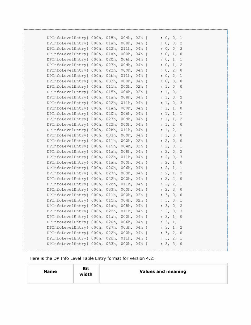
DPInfoLevelEntry{ 000h, 015h, 004h, 02h } ; 0, 0, 1
DPInfoLevelEntry{ 000h, 01ah, 008h, 04h } ; 0, 0, 2
DPInfoLevelEntry{ 000h, 022h, 011h, 04h } ; 0, 0, 3
DPInfoLevelEntry{ 000h, 01ah, 000h, 04h } ; 0, 1, 0
DPInfoLevelEntry{ 000h, 020h, 006h, 04h } ; 0, 1, 1
DPInfoLevelEntry{ 000h, 027h, 00dh, 04h } ; 0, 1, 2
DPInfoLevelEntry{ 000h, 022h, 000h, 04h } ; 0, 2, 0
DPInfoLevelEntry{ 000h, 02bh, 011h, 04h } ; 0, 2, 1
DPInfoLevelEntry{ 000h, 033h, 000h, 04h } ; 0, 3, 0
DPInfoLevelEntry{ 000h, 011h, 000h, 02h } ; 1, 0, 0
DPInfoLevelEntry{ 000h, 015h, 004h, 02h } ; 1, 0, 1
DPInfoLevelEntry{ 000h, 01ah, 008h, 04h } ; 1, 0, 2
DPInfoLevelEntry{ 000h, 022h, 011h, 04h } ; 1, 0, 3
DPInfoLevelEntry{ 000h, 01ah, 000h, 04h } ; 1, 1, 0
DPInfoLevelEntry{ 000h, 020h, 006h, 04h } ; 1, 1, 1
DPInfoLevelEntry{ 000h, 027h, 00dh, 04h } ; 1, 1, 2
DPInfoLevelEntry{ 000h, 022h, 000h, 04h } ; 1, 2, 0
DPInfoLevelEntry{ 000h, 02bh, 011h, 04h } ; 1, 2, 1
DPInfoLevelEntry{ 000h, 033h, 000h, 04h } ; 1, 3, 0
DPInfoLevelEntry{ 000h, 011h, 000h, 02h } ; 2, 0, 0
DPInfoLevelEntry{ 000h, 015h, 004h, 02h } ; 2, 0, 1
DPInfoLevelEntry{ 000h, 01ah, 008h, 04h } ; 2, 0, 2
DPInfoLevelEntry{ 000h, 022h, 011h, 04h } ; 2, 0, 3
DPInfoLevelEntry{ 000h, 01ah, 000h, 04h } ; 2, 1, 0
DPInfoLevelEntry{ 000h, 020h, 006h, 04h } ; 2, 1, 1
DPInfoLevelEntry{ 000h, 027h, 00dh, 04h } ; 2, 1, 2
DPInfoLevelEntry{ 000h, 022h, 000h, 04h } ; 2, 2, 0
DPInfoLevelEntry{ 000h, 02bh, 011h, 04h } ; 2, 2, 1
DPInfoLevelEntry{ 000h, 033h, 000h, 04h } ; 2, 3, 0
DPInfoLevelEntry{ 000h, 011h, 000h, 02h } ; 3, 0, 0
DPInfoLevelEntry{ 000h, 015h, 004h, 02h } ; 3, 0, 1
DPInfoLevelEntry{ 000h, 01ah, 008h, 04h } ; 3, 0, 2
DPInfoLevelEntry{ 000h, 022h, 011h, 04h } ; 3, 0, 3
DPInfoLevelEntry{ 000h, 01ah, 000h, 04h } ; 3, 1, 0
DPInfoLevelEntry{ 000h, 020h, 006h, 04h } ; 3, 1, 1
DPInfoLevelEntry{ 000h, 027h, 00dh, 04h } ; 3, 1, 2
DPInfoLevelEntry{ 000h, 022h, 000h, 04h } ; 3, 2, 0
DPInfoLevelEntry{ 000h, 02bh, 011h, 04h } ; 3, 2, 1
DPInfoLevelEntry{ 000h, 033h, 000h, 04h } ; 3, 3, 0
Here is the DP Info Level Table Entry format for version 4.2:
Name Bit
width Values and meaning
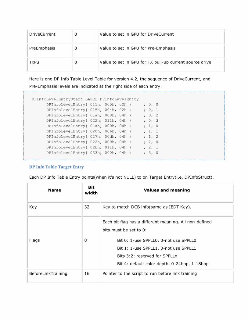
DriveCurrent 8 Value to set in GPU for DriveCurrent
PreEmphasis 8 Value to set in GPU for Pre-Emphasis
TxPu 8 Value to set in GPU for TX pull-up current source drive
Here is one DP Info Table Level Table for version 4.2, the sequence of DriveCurrent, and
Pre-Emphasis levels are indicated at the right side of each entry:
DPInfoLevelEntryStart LABEL DPInfoLevelEntry
DPInfoLevelEntry{ 011h, 000h, 02h } ; 0, 0
DPInfoLevelEntry{ 015h, 004h, 02h } ; 0, 1
DPInfoLevelEntry{ 01ah, 008h, 04h } ; 0, 2
DPInfoLevelEntry{ 022h, 011h, 04h } ; 0, 3
DPInfoLevelEntry{ 01ah, 000h, 04h } ; 1, 0
DPInfoLevelEntry{ 020h, 006h, 04h } ; 1, 1
DPInfoLevelEntry{ 027h, 00dh, 04h } ; 1, 2
DPInfoLevelEntry{ 022h, 000h, 04h } ; 2, 0
DPInfoLevelEntry{ 02bh, 011h, 04h } ; 2, 1
DPInfoLevelEntry{ 033h, 000h, 04h } ; 3, 0
DP Info Table Target Entry
Each DP Info Table Entry points(when it's not NULL) to on Target Entry(i.e. DPInfoStruct).
Name Bit
width Values and meaning
Key 32 Key to match DCB info(same as IEDT Key).
Flags 8
Each bit flag has a different meaning. All non-defined
bits must be set to 0:
Bit 0: 1-use SPPLL0, 0-not use SPPLL0
Bit 1: 1-use SPPLL1, 0-not use SPPLL1
Bits 3:2: reserved for SPPLLx
Bit 4: default color depth, 0-24bpp, 1-18bpp
BeforeLinkTraining 16 Pointer to the script to run before link training

AfterLinkTraining 16 Pointer to the script to run after link training
BeforeLinkSpeed 16 Pointer to an array of scripts to run before set up link speed
EnableSpread 16 Pointer to script to run when enable spread
DisableSpread 16 Pointer to script to run when disable spread
DisableLT 16 Pointer to script to run to disable what was set up by
BeforeLinkTraining
LevelEntryTableIndex 8 The index to Level Entry Table to use
HBR2MinVDTIndex 8 Reserved
Before Link Training Script
This script is pointed by BeforeLinkTraining in DP Info Table Target Entry. It should be run
before link training.
After Link Training Script
This script is pointed by AfterLinkTraining in DP Info Table Target Entry. It should be run
after link training.
Before Link Speed
This is an array of scripts which is pointed by BeforeLinkSpeed in DP Info Table Target
Entry. It should be run before set up and/or change link speed. As it is now, there are four
link speeds defined. Each entry in the array is LinkRateMode struct which is defined below.
GP100 will be the first chip to have 4 link speeds with the introduction of HBR3. Kepler and
Maxwell have 3 link speed entries.
Name Bit
width Values and meaning
LinkRate 8 Indicate the link rate, 06h=1.62G, 0Ah=2.7G, 14h=5.4G,
1Eh=8.1G

LinkRatePtr 16 Pointer to the script to run for this link rate
BeforeLinkSpeed_SOR_ALL LABEL LinkRateMode
LinkRateMode { 1Eh, OFFSET BeforeLinkSpeed_SOR_ALL_810 }
LinkRateMode { 14h, OFFSET BeforeLinkSpeed_SOR_ALL_540 }
LinkRateMode { 0Ah, OFFSET BeforeLinkSpeed_SOR_ALL_270 }
LinkRateMode { 06h, OFFSET BeforeLinkSpeed_SOR_ALL_162 }
Enable Spread Script
This script is pointed by EnableSpread in DP Info Table Target Entry. It should be run before
enable spread.
Disable Spread Script
This script is pointed by DisableSpread in DP Info Table Target Entry. It should be run
before disable spread.
Disable Link Training Script
This script is pointed by DisableLT in DP Info Table Target Entry. It should be run to disable
what was set up by BeforeLinkTraining.
--
Last updated 7/14/16